
A
Ev
In tmecusvaluto s
utoCAD
veryth
this paper, we eet the needs ostom tag formaues from one cset it for differ
D P&ID
ing fro
will discuss all of end users. Leats that inheritcomponent to ent symbols, in
D Custo
m Tags
the key conceearn how to cut properties froanother and d
ncluding inline
omizati
s and A
epts of tags, anustomize AutoCom different sodefine new rule
Equipment be
on:
Annotat
notations and CAD P&ID to crources. Learn aes for acquisitioehavior to achi
tions to
symbols, withreate and use cabout propertyon. Learn abouieve desired w
o Symb
h special emphcustom symbo
y acquisition tout the Join Typ
workflow.
bols
asis on customols, and define o propagate prpe functionality
mization to and utilize operty
y and how

Aut
Co
I. In
II. P
A
B
III.
A
B
C
IV.
A
B
C
D
E
F
G
H
I
J
K
toCAD P&ID Cu
ontents
ntroduction ..
Project: Defa
A. What is a D
B. What is a T
Tags vs. Anno
A. What is a T
B. What is an
C. What do w
Tag Formats
A. Defining a
B. Properties
1. P&ID Cla
2. Drawing
3. Project P
C. Expression
1. Expressi
2. Using Ex
D. Auto-Gene
1. Simple A
2. Property
E. Delimiters .
F. Assigning t
G. Tagging Pr
H. How Tags a
I. Notes on U
J. Tag Behavio
K. Pitfalls and
ustomization
.....................
ult vs. Templa
Default Projec
Template Proj
otations .......
Tag in AutoCA
Annotation i
we mean by “t
....................
Tag Format f
....................
ass Definition
Properties ..
Properties ....
s ..................
on Syntax ....
xpressions .....
eration ..........
Auto-generati
y based Auto-
.....................
he Tag to an
ompt Behavio
are Stored ....
niqueness ....
or during Clon
d Workaround
.....................
ate ................
ct? ................
ject? .............
.....................
AD P&ID? ......
n AutoCAD P
tagging” in Au
.....................
or a family of
.....................
s -Properties
.....................
.....................
.....................
.....................
.....................
.....................
on ................
-generation ..
.....................
Asset ............
ors and the G
.....................
.....................
ning ..............
ds ..................
.....................
.....................
.....................
.....................
.....................
.....................
&ID? ............
utoCAD P&ID
.....................
f P&ID Class D
.....................
.....................
.....................
.....................
.....................
.....................
.....................
.....................
.....................
.....................
.....................
.....................
Graphical Style
.....................
.....................
.....................
.....................
......................
......................
......................
......................
......................
......................
......................
? ...................
......................
Definitions ....
......................
......................
......................
......................
......................
......................
......................
......................
......................
......................
......................
......................
e ...................
......................
......................
......................
......................
.....................
.....................
.....................
.....................
.....................
.....................
.....................
.....................
.....................
.....................
.....................
.....................
.....................
.....................
.....................
.....................
.....................
.....................
.....................
.....................
.....................
.....................
.....................
.....................
.....................
.....................
.....................
.....................
.....................
.....................
.....................
.....................
.....................
.....................
.....................
.....................
.....................
.....................
.....................
.....................
.....................
.....................
.....................
.....................
.....................
.....................
.....................
.....................
.....................
.....................
.....................
.....................
.....................
.....................
......................
......................
......................
......................
......................
......................
......................
......................
......................
......................
......................
......................
......................
......................
......................
......................
......................
......................
......................
......................
......................
......................
......................
......................
......................
......................
......................
Page 2
............... 4
............... 4
............... 4
............... 4
............. 11
............. 12
............. 12
............. 12
............. 12
............. 13
............. 14
............. 14
............. 17
............. 19
............. 20
............. 20
............. 28
............. 29
............. 29
............. 30
............. 38
............. 39
............. 50
............. 51
............. 53
............. 54
............. 54

AutoCAD P&ID Customization Page 3
L. Special Behavior for Line Segment Tag Uniqueness ............................................................................................. 57
V. Annotation Styles ...................................................................................................................................................... 57
A. Simple Annotations .............................................................................................................................................. 57
B. Compound Annotations ........................................................................................................................................ 58
C. Creating a New Annotation Style .......................................................................................................................... 61
D. Assigning Format Strings to Attribute Definitions ................................................................................................ 64
1. Using Expressions in Annotation Format Strings .............................................................................................. 72
2. Using Annotations to Edit Underlying Data ...................................................................................................... 75
3. Special Behaviors --Reducer Annotation Styles ................................................................................................ 76
E. Principles of Dynamic Sizing .................................................................................................................................. 77
1. A brief overview of Dynamic Block Principles ................................................................................................... 77
2. Linear Parameters in Annotation Block Definitions .......................................................................................... 78
3. TotalX and TotalY .............................................................................................................................................. 83
VI. Custom Symbols ...................................................................................................................................................... 84
A. Creating Custom Symbols ..................................................................................................................................... 84
1. Block Definition Management .......................................................................................................................... 84
2. Creating a new Graphical Style with a new Symbol.......................................................................................... 85
3. Graphical Style Properties................................................................................................................................. 90
4. Manually switching between Graphical Styles ................................................................................................. 91
5. Associating Graphical Styles with a Property .................................................................................................... 91
6. Using Multiple Graphical Style for an Asset that Spans Drawings .................................................................... 94
7. A note about Attachment Points ...................................................................................................................... 95
B. Dynamic Assets ..................................................................................................................................................... 96
1. Special Behaviors of Off Page Connectors ........................................................................................................ 97
2. Special Behaviors of Instruments ...................................................................................................................... 99
VII. Property Propagation/Acquisition .......................................................................................................................... 99
VIII. Appendix .............................................................................................................................................................. 102
A. Format string syntax ........................................................................................................................................... 102
B. APIs ..................................................................................................................................................................... 104

AutoCAD P&ID Customization Page 4
I. Introduction AutoCAD® P&ID is a design software use to create, modify, and manage piping and instrumentation diagrams. Built on the latest AutoCAD® platform, AutoCAD P&ID is easy to use and familiar to designers and process plant engineers. Made specifically for P&ID designers and drafters, AutoCAD P&ID enables faster and more efficient creation, manipulation, and revisions to P&ID drawings.
This course will cover key concepts in P&ID diagrams --tags, annotations, and symbols --with special emphasis on customization to meet the needs of end users and their organizations. Topics covered include how to create and use custom symbols; how to define and utilize custom tag formats that utilize properties from different sources and use alpha-numeric expressions in formatting. There are examples of how annotations can be formatted and placed inside custom blocks which are dynamically resized when the size of the text changes. At the end of the course, the reader should feel confident about customizing P&ID for their own usage.
These things will be covered in this document:
• Tagging vs. Annotating: Key Concepts • Creating custom Tag Formats: Properties and Expressions • Creating custom Annotation Styles: Block Definitions and Evaluatable Strings • Principles of Dynamic Sizing • Creating custom symbols for Assets
II. Project: Default vs. Template
A. What is a Default Project? • A preset project is used when a new project has not been specified by the user • Default settings are set to what the majority of people would choose. There is often no reason to change
them.
B. What is a Template Project? • A customized project value used when a setting has been specified by the Administrator (user). • A copy of the default, new, existing, Sample or finished Project • A Template Project contains all defined settings, folders and required for a client(s).
For many companies, the default standard Project may not be sufficient. It is a good base for starting a project, but there are always specific company's palettes, symbols, environments and settings that require customization. A Project contains everything you need to create process and instrument diagrams. Items such as symbols, annotations, and templates as well as the location to store your settings and drawings are part of your project.

Aut
See
toCAD P&ID Cu
e default Auto
Examples
ustomization
oCAD 2015 P&
s of the default P
&ID folder be
Project (left) and
elow.
d the example Teemplate Project ((right)
Page 5

Aut
Bel
Wh
toCAD P&ID Cu
low is a Client
hen creating a
ustomization
t specific Tem
a new project
mplate folder
t using the te
structure
mplate to creeate it, the foollowing proceedure will be
crucial.
Page 6

Aut
Staclic
See
Lef
toCAD P&ID Cu
art the Projecck on the
e example be
ft Click “Next”
ustomization
t creator Wizbutton and
elow:
”
ard, fill in the find the tem
e informationmplate project
and check “ct to use.
copy settings from existing
g project” box
Page 7
x, then

Aut
Evesuc
Lef
Ma3D
Lef
toCAD P&ID Cu
en though yoch as file path
ft Click “Next”
ake sure to spmodels DWG
ft Click “Next”
ustomization
u chose a defhs.
”
pecify the DireG directory.
”, and choose
fine template
ectory where
e the SQLite lo
e, you still hav
e your P&ID d
ocal database
ve the option
rawings will b
e.
to change so
be stored. Lef
ome settings d
ft click “Next”
during Projec
” and specify
Page 8
ct creation
the Plant

Aut
Noaft
toCAD P&ID Cu
w you are at er creating pr
ustomization
the end of throject” (recom
he Project cremmended) or
eation. You car click “Finish”
an now check ”.
mark on the
“Edit additioonal project se
Page 9
ettings

Aut
Wh
dir
toCAD P&ID Cu
hen finished,
ectory”
ustomization
open the Pro
button t
oject Setup an
to define app
nd look at the
propriate loca
e similarities.
tion.
Remember too click on thee “User define
Page 10
ed reports

Aut
Whbel
So
Thiapp
Pro
Defoware
A M
IIIThedesto tpreove
toCAD P&ID Cu
hen finished, low:
the question
• Why is aink about theply fonts, ens
oject Templat
fault projectswn templates.e created, you
Master templ
I. Tags ve word “Tag”sign domain, the Tagging aevent confusierloaded mea
ustomization
the new Proj
remains…..
a Template be time it woulsure all is line
tes can help e
s are a great sAutoCAD 20
u have the ab
ate is the beg
vs. Ann and the worin various Au
and Annotatioon in the remanings for the
ect created u
etter than thd take to sped up and mat
ensure a cons
start, but mos10 P&ID mak
bility to modif
ginning of a n
otationd “Annotatio
utoCAD featuron features as
mainder of thie word “tag” l
using the clien
e original? cify all the patching to you
sistent look an
st developerses it extreme
fy them.
ew, updated,
ns n” have a varres, and in ths built for ands course. In pleads to conf
nt define tem
age size/layour company's s
nd feel.
s and adminisely easy to cre
, and better C
riety of usagee AutoCAD P&d shipped witparticular, priusion.
mplate file crea
ut properties,standards.
strators will weate your ow
Client specific
es in ordinary &ID product.th the AutoCAor experience
ation should
, Toolbars, Bl
want to know n templates.
c Master proj
English, in pl The followin
AD P&ID prode has shown t
look like the
ocks, Layers,
how to creatIn addition, o
ect Template
lant engineerng discussion duct, and is mthat too man
Page 11
example
Borders,
te their once they
e.
ring and is specific
meant to ny

AutoCAD P&ID Customization Page 12
A. What is a Tag in AutoCAD P&ID? • A Tag is a unique identifier for an asset or line segment • A Tag is DATA • A Tag lives in the database (tracked as a property ) • An asset or line segment can have only one Tag • A Tag is built up of sub parts as defined by the Tag Format
B. What is an Annotation in AutoCAD P&ID? • An Annotation is text (and optional geometry) in the drawing which presents information about the asset
or line segment. • An Annotation is graphical. • An Annotation lives in the drawing, but is linked to the database. • An Annotation need not be unique • An asset or line segment may have multiple Annotations • The text shown by an Annotation is determined by the Format String as defined in the Annotation Style’s
block definition. • The text shown by the Annotation may include the asset or line segment’s Tag property, but it is not “the”
Tag. It is still an annotation.
C. What do we mean by “tagging” in AutoCAD P&ID? • “Tagging” means assigning the values for the unique identifier of a given asset or line segment into the Data
Cache • “Tagging” means creating and storing data. • “Tagging” is done via the Assign Tag dialog. • Placing an annotation in the drawing that shows the tag property is NOT “Tagging”, it is “Annotating”.
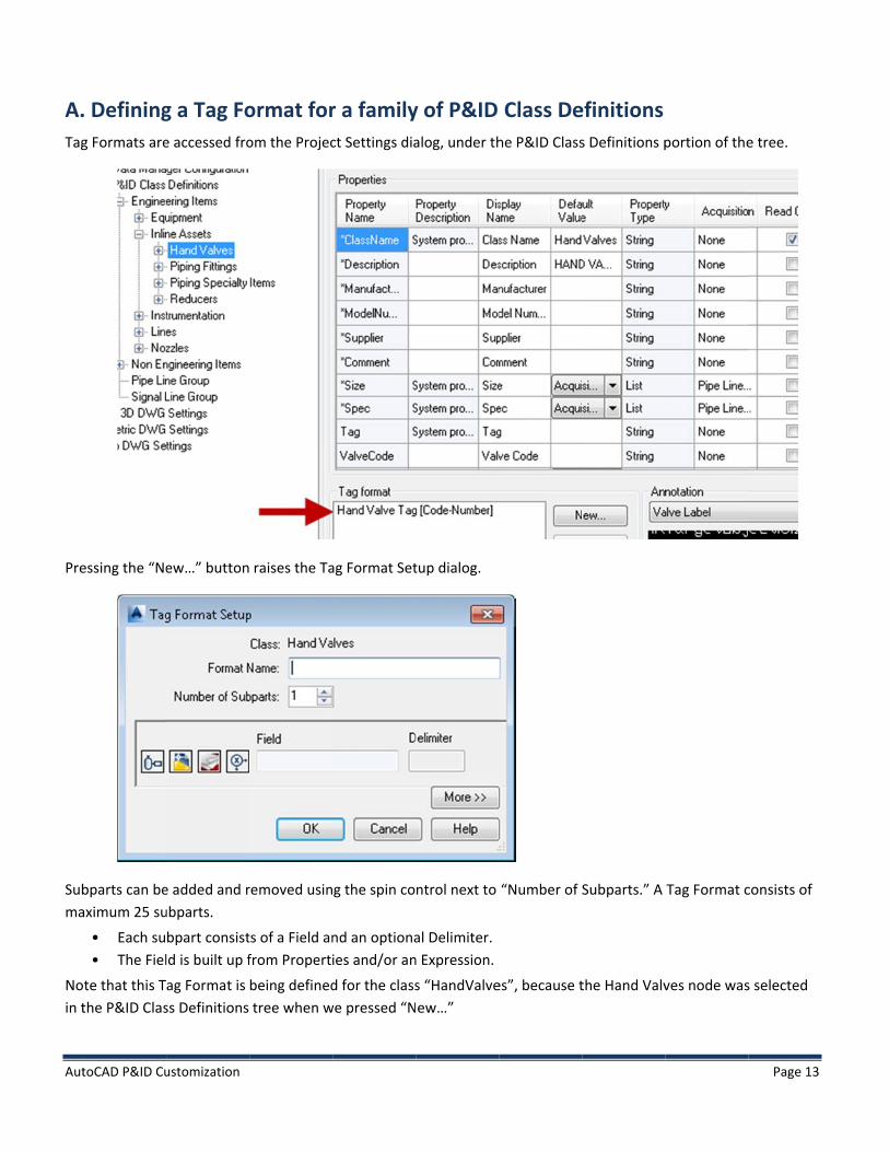
IV. Tag Formats Tag Formats are defined at a given level in the P&ID Class Definitions hierarchy, and once defined, are available to be used by all P&ID classes below that node in the Class Definitions tree. The subparts consist of Properties and/or Expressions, and may be Autogenerated. The subparts are concatenated together into a single value, and this completed tag value is validated for uniqueness and stored as a tag property in the Data Cache. We’ll examine each of these concepts, and discuss a few pitfalls that should be avoided.
Aut
A.Tag
Pre
Subma
Noin t
toCAD P&ID Cu
. Definingg Formats are
essing the “Ne
bparts can beaximum 25 su
• Each su• The Fiel
te that this Tthe P&ID Clas
ustomization
g a Tag Foe accessed fro
ew…” button
e added and rubparts.
bpart consistld is built up f
ag Format is ss Definitions
ormat forom the Projec
raises the Ta
removed usin
ts of a Field anfrom Properti
being definedtree when w
r a familyct Settings dia
ag Format Set
g the spin co
nd an optionaies and/or an
d for the classwe pressed “N
y of P&ID alog, under th
tup dialog.
ntrol next to
al Delimiter. n Expression.
s “HandValveew…”
Class Dehe P&ID Class
“Number of S
es”, because t
efinitions s Definitions p
Subparts.” A
the Hand Valv
portion of the
Tag Format c
ves node was
Page 13
e tree.
consists of
s selected

Aut
ThiDef
B.A TProsub
Draovethe
1. Pre
In mbeipro
toCAD P&ID Cu
is Tag Formatfinitions hiera
PropertiTag Format moject. The firsbpart, and are
awing and Prerall tag prope Drawing and
P&ID Class Dessing the left
most situatioing designed.operties, Valv
ustomization
t will be availaarchy; in othe
ies may specify pr
t three buttoe mutually ex
oject propertperty, but assid/or Project.
Definitions -tmost button
ns it is necess Therefore, th
ve Code, defin
able to all chier words, this
operties of thons next to eaxclusive. We w
ties are read fignments maThese proper
-Properties raises the Se
sary to specifhis example nned for Hand
ild P&ID classs Tag Format w
he object to bach sub part pwill examine e
from the Drawde to these prties are used
elect Class Pro
fy a propertynavigates to tValves.
ses defined atwill be availa
be tagged, proprovide a meaeach in turn.
wing and Projroperties via
d for initializat
operty dialog
that actually the HandValv
t a more deepble for all Ha
operties of thans to select a
ject respectivthe tagging otion only.
.
exists on theves node in th
ply nested levnd Valves.
he Drawing, oa property of
vely, and will boperation will
e class for whihe Class tree,
vel in the P&I
or properties of each type fo
become part l NOT be stor
ich the Tag Foand selects o
Page 14
D Class
of the or the
of the red back to
ormat is one of the

Aut
Thein t
As firs
If t
No
Tarwhpro
Any“Va
The
toCAD P&ID Cu
e “Use Targetthe Tag Form
can be seen, st button now
he “Use Targ
tice that the
rgetObject indhich this Tag Foperty, is gen
y property avalveCode” is a
ere is an exce
ustomization
t Object’s Proat Setup.
the Propertyw appear raise
et Object’s Pr
Property is n
dicates to theFormat is beinerally approp
vailable at a ga property of
eption to the
operty” check
y has been speed. This indica
roperty” chec
ow defined u
e program thang defined. It priate to use.
given level in tf HandValves,
requirement
kbox is also se
ecified as Tarates that a cla
ckbox were d
using the actu
at the requesis a shortcut
the hierarchy you can be c
to specify a p
elected. Press
rgetObject.Vaass property
eselected, th
al class name
sted propertyin the nomen
y is always avacertain that it
property defi
sing OK yields
alveCode. Alsois in use.
he result wou
e: HandValve
y is expected tnclature, and
ailable at thet is a property
ned on the P&
s the followin
o, notice that
ld have looke
s.ValveCode.
to be defined if you are ca
child level. Ty of Gate Valv
&ID class bein
g result for th
t the graphics
ed like this:
d for the P&IDreful in selec
That is, since ve, Ball Valve,
ng targeted.
Page 15
he subpart
s for the
D class for ting the
, etc.

Aut
In stagPip
To tru
toCAD P&ID Cu
some special gged, as part opeLineGroup a
utilize a classue:
• The pro• The actu
ustomization
situations, yoof the tag valas two of the
s property fro
operty must bual class mus
ou may want ue. For examsubparts.
om a class oth
be from a clast be specified
to include a pmple, the Tag F
her than that
s that shares d --the Target
property fromFormat for Pi
for which the
a direct relattObject nome
m a P&ID claspeLines spec
e Tag Format
tionship to thenclature can
ss directly relaifies a proper
is defined, th
he target classnot be used.
ated to the iterty from the
he following m
s.
Page 16
em being
must be

Aut
2. Pre
A dfol
Thepro
toCAD P&ID Cu
Drawing Proessing the sec
drawing propelowing in the
e second buttoperty is spec
ustomization
operties cond button b
erty may be ssubpart.
ton now showcified in the F
beside the su
specified as o
ws the raised ield by Categ
bpart raises t
ne subpart of
graphics, indory and Prop
the Select Dra
f a Tag Forma
dicating that aerty.
awing Proper
at. Selecting t
a Drawing pro
ty dialog.
the propertie
operty is selec
es above yield
cted, and the
Page 17
ds the
e Drawing

Aut
Use
Any
toCAD P&ID Cu
ers may add c
y custom Dra
ustomization
custom Draw
awing propert
wing categorie
ties added he
es and proper
ere will be ava
rties in the Pr
ailable to sele
oject Setup d
ect from the S
dialog.
Select Drawinng Property d
Page 18
ialog.
Aut
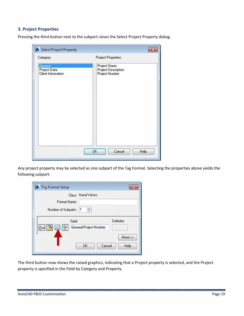
3. Pre
Anyfol
Thepro
toCAD P&ID Cu
Project Propessing the thi
y project prolowing subpa
e third buttonoperty is spec
ustomization
perties rd button nex
perty may beart:
n now shows cified in the F
xt to the subp
e selected as o
the raised grield by Categ
part raises the
one subpart o
raphics, indicaory and Prop
e Select Proje
of the Tag For
ating that a Perty.
ect Property d
rmat. Selectin
Project proper
dialog.
ng the proper
rty is selected
rties above yi
d, and the Pro
Page 19
ields the
oject

Aut
Use
Any
C.
1. Exp
Whprocon
toCAD P&ID Cu
ers may add c
y custom Pro
Expressi
Expression Spressions def
• The cha• The cha• The cha• The cha
hen expressiooperty value injunction wit
ustomization
custom Proje
oject propertie
ions
Syntax ine a simple s
aracter ‘A’ spearacter ‘a’ spearacter ‘N’ spearacter ‘*’ spe
ons are used iis being assigh a property,
ct categories
es added her
syntax for cha
ecifies an uppecifies any alpecifies a digit.ecifies that an
n conjunctionned, via the A it is called a
and properti
e will be avai
aracter match
per case alphaphabetic char.
ny number of
n with a propAssign Tag dia“pure” expre
ies in the Proj
lable to selec
hing.
abetic characacter.
the previous
perty, they enalog. When anession, and als
ject Setup dia
ct from the Se
cter.
s type of char
nforce the typn expression so enforces th
alog.
elect Project P
acter (A, a, o
pe of input this used indephe type of inp
Property dial
r N) may follo
at is acceptedpendently, noput.
Page 20
og.
ow.
d when the ot in

Aut
EnfdiaHo
The
The
Themo
a)
In texp
toCAD P&ID Cu
forcement is alog, and an awever misma
e upper two s
e Expression
e Result portiodification of
Example 1
the example apression built
• a --requ• * after t
ustomization
“weak”, meanattempt to coatched input t
sections of th
portion of the
ion of the diathe expressio
1: Any alph
above, the Ext in the Result
uires any uppethe a --means
ning that misrrect the inputhat cannot b
he Define Exp
e dialog prov
log shows whon, or disablin
habetic ch
xpression spet box is: a*
er or lower cas any number
smatched inpuut automaticabe corrected is
ression dialog
ides a means
hat the expreng of the expr
aracters, a
ecifies Text Ch
ase characterr of upper or
ut will result ially via paddins still accepte
g illustrate th
s to define the
ssion looks liression.
any length
haracters. It d
r lower case ch
in user feedbng, truncatio
ed.
his syntax in a
e most comm
ke as it is con
h
does not spec
haracters.
ack (red text)n, or upperca
action.
mon expressio
nstructed, and
cify uppercase
) in the Assignasing, if possib
ons.
d also allows
e or a length.
Page 21
n Tag ble.
direct
Thus the

Aut
b)
He
toCAD P&ID Cu
Example 2
re, checking t
• A --requ• * after t
ustomization
2: Upper c
the “Upperca
uires an uppethe A --mean
ase charac
ase” box in th
er case characs any numbe
cters, any
e Expression
cter r of upper cas
length
area of the d
se characters
dialog has cha
s.
anged the Ressult to: A*
Page 22

Aut
c)
In tres
Thichatru
toCAD P&ID Cu
Example 3
this example,sult to: AAA
• Each A r• The aste
is expression aracters will b
uncated.
ustomization
3: Upper ca
, selecting the
requires an uerisk (*) is no
requires exacbe represente
ase charac
e “Fixed Leng
pper case cha longer show
ctly 3 upper ced by a ‘?’ cha
cters, fixed
th” checkbox
aracter. wn.
case charactearacter. If too
d length
x and increme
er as input. If to many chara
enting the spi
too few characters are inpu
in control to 3
acters are input, the extran
3 has change
put, the missineous charact
Page 23
d the
ng ters will be

Aut
d)
In t
N*
toCAD P&ID Cu
Example 4
this example,
• N -requ• * after t
ustomization
4: Number
, selecting the
ires a digit the N --allows
rs, any len
e Numbers ra
s as many dig
gth
adio button in
gits as desired
n the Expressi
d.
ion has changged the resultt to:
Page 24
Aut
e)
In tres
Nois s
toCAD P&ID Cu
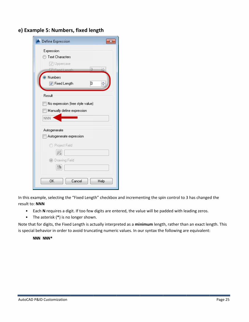
Example 5
this example,sult to: NNN
• Each N • The aste
te that for digspecial behav
NNN NN
ustomization
5: Number
, selecting the
requires a digerisk (*) is no
gits, the Fixedior in order to
NN*
rs, fixed le
e “Fixed Leng
git. If too few longer show
d Length is aco avoid trunc
ngth
th” checkbox
digits are enwn.
ctually interprcating numeri
x and increme
tered, the va
reted as a mic values. In o
enting the spi
lue will be pa
nimum lengtour syntax the
in control to 3
added with le
th, rather thae following ar
3 has change
eading zeros.
n an exact lenre equivalent:
Page 25
d the
ngth. This :

Aut
f)
In t“Fruse
Thecreany
toCAD P&ID Cu
Example 6
this example, ree Style”. Wher should be a
e same thing eating a subpaything they li
ustomization
6: No Expre
the “No Exprehen this optionallowed to en
can be accomart involving ake for the sub
ession
ession” checkbn of the Exprenter any value
mplished by na property. Wbpart.
box has been ssion dialog ise they like for
not opting to When this opt
selected in ths being used inr the property
use an expresion is used as
he “Result” secn conjunction y.
ssion at all (ns a pure expre
ction. This reswith a Proper
not pressing thession, the us
sult box now srty, it indicate
he 4th
buttonser is allowed
Page 26
shows es that the
) when d to enter
Aut
g)
In tno
Thi
The
The
toCAD P&ID Cu
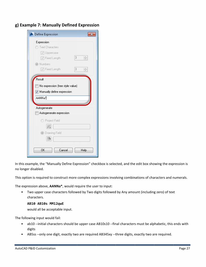
Example 7
this example,longer disabl
is option is re
e expression
• Two upcharact
AB10 Awould a
e following in
• ab10 --idigits
• AB5ss --
ustomization
7: Manuall
, the “Manualed.
equired to con
above, AANNper case charers.
AB10s MM12all be accepta
nput would fa
nitial charact
-only one dig
ly Defined
lly Define Exp
nstruct more
Na*, would re
racters follow
qwE ble input.
il:
ters should be
it, exactly two
Expressio
pression” che
complex exp
equire the use
wed by Two di
e upper case
o are require
on
ckbox is selec
ressions invo
er to input:
igits followed
AB10s10 --fin
d AB345xy --t
cted, and the
olving combin
d by Any amo
nal characters
three digits, e
e edit box sho
nations of cha
unt (including
s must be alp
exactly two a
owing the exp
aracters and n
g zero) of tex
phabetic, this
re required.
Page 27
pression is
numerals.
xt
ends with

Aut
2. TheDef
Whinp
If tthe
Nouse
Whnot
toCAD P&ID Cu
Using Expree first three bfine Expressio
hen an expresput for that Pr
he expressione ValveCode p
tice that bothe. In addition,
hen an exprest associated w
ustomization
essions buttons, specon dialog, ma
ssion is used roperty.
n from Exampproperty, the
h the Class Pr, notice that t
ssion is used with any prop
ifying the proay be used eit
in conjunctio
ple 3, requirinresulting sub
roperty and Ethe expressio
alone, it acts perty.
operty sourcether alone, or
n with one of
ng three uppebpart would a
xpression buton is being sho
to require th
e, are mutuallr in conjunctio
f the Property
ercase alphabappear as follo
ttons show thown in square
e user to inp
y exclusive. Ton with one o
y buttons, it a
betic characteows:
he raised grape brackets aft
ut a pure alp
The fourth buof the Proper
acts to enforc
ers, were use
phics, indicatter the prope
habetic or nu
utton, which rrty buttons.
ce a specific ty
d in conjunct
ting that botherty.
umeric value w
Page 28
raises the
ype of
tion with
h are in
which is

Aut
If tfolthenot
D.Som
1. SSim
If t
TheAut
toCAD P&ID Cu
he expressionlows: Notice te Property but show any pr
. Auto-Geme values can
Simple Automple Auto-gen
• Every su• Every p• The only
hese requirem
e Tag Formattogeneration
ustomization
n from Exampthat the Exprttons show troperty. This
enerationn be Auto-gen
o-generationneration has t
ubpart but onroperty subpay non-proper
ments are me
for Nozzles p:
ple 5, requirinression buttonhe raised grais a “pure” ex
n nerated. Ther
n the following
ne is a properart has a knowrty subpart is
et, it will calcu
provides an e
ng 3 numbersn shows the rphics. In addixpression.
re are two ap
g requirement
rty wn value a pure nume
ulate a nume
xample of a T
s, were used braised graphicition, the Fiel
pproaches to A
ts:
eric expressio
ric value that
Tag Format th
by itself, the cs, indicating d shows ONL
AutoGenerat
n
t results in a u
hat has been
resulting suban expressio
LY the express
tion.
unique Tag.
authored to s
part would aon is in use, busion, NNN, an
support simp
Page 29
ppear as ut none of nd does
ple

Aut
2. Pro
Exaexacon
Exa
Botreq
a) Yousel
toCAD P&ID Cu
Property baoperty based
ample 1: Assuample, all pumntain a nume
ample 2: Assu
th of these exquirements to
1) You mu
2) You muproperty i
Auto-geneu can access tecting “Draw
ustomization
ased Auto-geAuto-generat
ume that the mps in drawinric subparts s
ume that all T
xamples can bo use propertust define and
ust indicate inis the auto-ge
eration bathe drawing A
wing Autogen
eneration ted values ca
Tag for all pung 1 should costarting from
Tanks in an en
be supportedty-based autod initialize the
n the tag formeneration bas
ased on DraAutogen propProperties.”
n be per-Draw
umps in a drawontain a num200, etc.
ntire project s
d with Propertogeneration:e autogen pro
mat that you asis
awing Properties by righ
wing or per-P
wing must refmeric subpart
should be num
ty based Auto
operties
are using auto
perties ht clicking on
Project.
flect which dstarting from
mbered incre
ogeneration.
o-generation,
the drawing
rawing contam 100, all pum
ementally acro
There are tw
, and which
in the Projec
ains the pumpmps in drawin
oss the entire
wo fundament
ct Workspace,
Page 30
p. For g 2 should
e project.
tal
, and
Aut
Sel
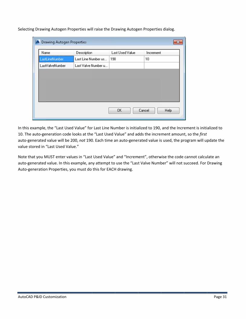
In t10.autval
NoautAut
toCAD P&ID Cu
ecting Drawi
this example,. The auto-geto-generatedue stored in “
te that you Mto-generatedto-generation
ustomization
ng Autogen P
, the “Last Usneration cod value will be“Last Used Va
MUST enter va value. In thisn Properties,
Properties wil
ed Value” fore looks at the
e 200, not 190alue.”
alues in “Lasts example, anyou must do
l raise the Dr
r Last Line Nue “Last Used V0. Each time a
t Used Value”ny attempt to
this for EACH
rawing Autoge
umber is initiaValue” and adan auto-gener
and “Increm use the “Last
H drawing.
en Properties
alized to 190, dds the increrated value is
ment”, otherwt Valve Numb
s dialog.
and the Increment amouns used, the pr
wise the code ber” will not s
ement is initit, so the first
rogram will up
cannot calcusucceed. For
Page 31
alized to
pdate the
late an Drawing

Aut
To Exp
toCAD P&ID Cu
use these vapression dialo
ustomization
lues, you musog.
st select the EExpression buutton on the T
Tag Format Setup dialog, tto raise the D
Page 32
Define

Aut
In tDraProto s
In acredia
toCAD P&ID Cu
this example,awing Field raoperty” dialogselect one. H
addition, neweation of a nealog to assign
ustomization
, we intend toadio button, ag. This dialog ere we can se
w Drawing Auw Drawing Atheir initial v
o auto-generaand press thepresents all t
elect “Last Lin
togen Properutogen Prope
values.
ate a numerice Drawing Fiethe defined Dne Number”,
rties can be aerty, but it is
c value basedld icon. Press
Drawing Autogwhich we init
dded by presnecessary to
on a Drawinsing this icon gen Propertietialized in the
ssing the “Newreturn to the
g Field. To doraises the “Sees already dee steps above
w…” button. e “Drawing Au
o so, we selecelect Drawingfined, and all
e.
This button autogen Prope
Page 33
ct the g Autogen ows you
allows the erties”

Aut
Aft
toCAD P&ID Cu
ter selecting “
ustomization
“Last Line Nummber”, the Define Expresssion dialog sh
ows the selecction.
Page 34

Aut
Theproval
b) Settha
toCAD P&ID Cu
e default viewoperty is in usue it is based
Auto-genetting up Projeat there is no
ustomization
w of “Define Tse. It shows thd. Pressing the
eration baect Auto-gene
project-level
Tag Format” dhe expressione “More>>” b
ased on Proeration Prope UI giving dire
dialog doesn’n N*, but it dobutton does s
oject Properties is similaect access.
t provide muoes not indicahow the addi
perties ar to setting u
uch feedback ate that autoitional inform
up Drawing Au
to indicate thgeneration is
mation.
uto-generatio
hat an autoges in effect or u
on Properties
Page 35
en upon what
s, except

Aut
Seldia
Prefrothe“Ne
toCAD P&ID Cu
ecting a Projealog, just as ab
essing the Proom the “Selecte same dialogew…” button
ustomization
ect Autogen pbove, except
oject Field icot Drawing Au
g. You may als.
property starthat the “Pro
on raises the “togeneration
so create new
ts with the “Doject Field” ra
“Select Projecn Property” diw Project Auto
Define Expresadio button m
ct Autogeneraialog in that togeneration P
ssion Dialog” must be select
ation Propertthe property AProperties fro
raised from tted.
ty” dialog. ThAND the initiom this dialog
the “Tag Form
is dialog diffeal values are g by pressing
Page 36
mat Setup”
ers slightly shown in the

Aut
Sinloc
toCAD P&ID Cu
nce Project Aucation, in cont
ustomization
utogen propetrast to the w
rties exist onway per-drawi
ce for the ening initializati
tire project, ion for each d
nitialization idrawing in the
is done from e project wor
this centralizrkspace.
Page 37
ed
Aut
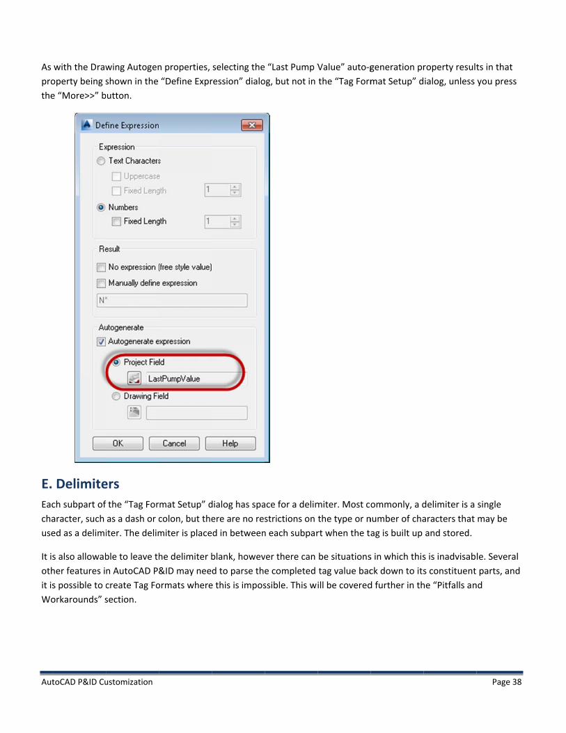
As prothe
E. Eacchause
It isothit isWo
toCAD P&ID Cu
with the Drawoperty being se “More>>” b
Delimitech subpart ofaracter, such ed as a delimi
s also allowabher features is possible to corkarounds” s
ustomization
wing Autogenshown in the
button.
ers f the “Tag Foras a dash or citer. The delim
ble to leave thn AutoCAD P&create Tag Fosection.
n properties, “Define Expr
mat Setup” dcolon, but themiter is place
he delimiter b&ID may nee
ormats where
selecting theression” dialo
dialog has spaere are no resd in between
blank, howevd to parse the
e this is impos
“Last Pump Vog, but not in
ace for a delimstrictions on t
n each subpar
ver there can e completed ssible. This wi
Value” auto-gthe “Tag Form
miter. Most cothe type or nrt when the ta
be situationstag value bacill be covered
generation prmat Setup” d
ommonly, a dnumber of chaag is built up
s in which thisck down to itsd further in th
roperty resultialog, unless
delimiter is a aracters that and stored.
s is inadvisabs constituent
he “Pitfalls an
Page 38
ts in that you press
single may be
le. Several parts, and
nd

Aut
F. To
No
RecinitProfol
toCAD P&ID Cu
Assignincomplete the
tice it utilizes
• The first• The sec• The thir• The fou• The last
it is admcall that the “tialized to a Loperties. This lows.
ustomization
g the Tage exercise abo
s most of the
t subpart is a ond subpart rd subpart is arth subpart is
t subpart is a missible (altho“Drawing Autast Used ValuTag Format a
g to an Asove, the follo
features prev
property of tis a pure numa Drawing pros a Project Provalue from a
ough perhapsogen Propert
ue of 190 andalso relies on
sset wing Tag For
viously discus
the object, anmeric expressioperty. operty PipeLine. Sin
s not advisablty” called “Lad an incremen
a Drawing pr
mat is being
ssed.
nd requires upion based on
ce HandValvee) to use a prst Line Numb
nt value of 10roperty and a
defined at th
pper case chaa Drawing Au
es are inline iroperty this wber”, being us0 in the sectioa Project prop
e HandValves
aracter inpututogen Prope
instruments tway. sed in the secon describing perty, which w
s level.
. erty.
that sit upon
cond subpart,Drawing Aut
will be initiali
Page 39
a PipeLine,
was ogen zed as

Aut
RigDra
toCAD P&ID Cu
ght clicking onawing Proper
ustomization
n the drawingrties dialog. In
g icon in the Pn the image b
Project worksbelow, the val
pace, and selue 51 is being
lecting the “Pg assigned to
Properties…” o the Drawing
menu item rag’s Area prope
Page 40
aises the erty.

Aut
ProPro
toCAD P&ID Cu
oject propertioject Number
ustomization
ies are initialir.
zed in the Prooject Settingss dialog. Below, the value 18238 is beinng assigned to
Page 41
o the

Aut
Aft
HeHa
SinIn tfro
toCAD P&ID Cu
ter a Tag Form
re we see thand Vales is “H
nce “Big Examthe following
om the picklist
ustomization
mat has been
at two Tag FoHand Valve Ta
mple Tag Form example, thet for the TagF
set up, it mu
ormats are noag [Code-Num
mat” was define new Tag FoFormatName
st be selected
w defined at mber].
ned at the Harmat is assignproperty.
d as the Tag F
the Hand Va
and Valves levned as the Tag
Format to use
lves level, an
vel, it is availag Format for
e for a given P
d that the de
able to be useBall Valves, o
P&ID class.
efault Tag For
ed by any Hanonly, by select
Page 42
mat for
nd Valve. ting it

Aut
Theava
Sel
As arrval
In aass
toCAD P&ID Cu
e following drailable on the
ecting “Assig
can be seen hrow only appeue by the inc
addition, the signed to thos
ustomization
rawing contae right click m
gn Tag” raises
here, the secoears when foccrement amou
Project and Dse properties
ins two Ball Venu of the Ba
the Assign Ta
ond propertycus is placed unt specified
Drawing base.
Valves, one ofall Valve.
ag dialog.
y has initializein that subpain the autoge
ed properties
f which is on
ed based on thart. Each pressen property.
have been in
a PipeLine. “A
he Drawing As of the incre
nitialized from
Assign Tag” is
Autogen Propement arrow w
m the values t
s an option th
perty. The incrwill incremen
that are curre
Page 43
hat is
rement nt the
ently

Aut
Weerr
NoTagbecstilnot
Aupadupp
toCAD P&ID Cu
e defined the ror; the text is
tice that the pg dialog tries cause the misll be acceptedt reflect the fi
tomatic corredding short apercasing alp
ustomization
ValveCode as presented in
preview of thto correct mi
smatch is too d. This “weak”final data in it
ection, depenalphabetic inpphabetic input
s requiring upn red.
he completed ismatched inpegregious (e.
” enforcements final forma
ding on the eput with trailint.
pper case cha
Tag in the topput automatic.g. entering d
nt anticipates t.
expression, cang ‘?’ charact
aracters, so e
p box shows cally, based o
digits when cha need to som
an include padters, truncatin
ntering lowe
the ValveCodon the expressharacters are metimes ente
dding short nung alphabetic
r case charac
de capitalizedsion. If correcspecified) the
er temporary
umeric valuesc input that is
ters appears
d. If possible, tction is not poe mismatchedinformation
s with leadings too long, an
Page 44
as an
the Assign ossible d input will that may
g zeros, d
Aut
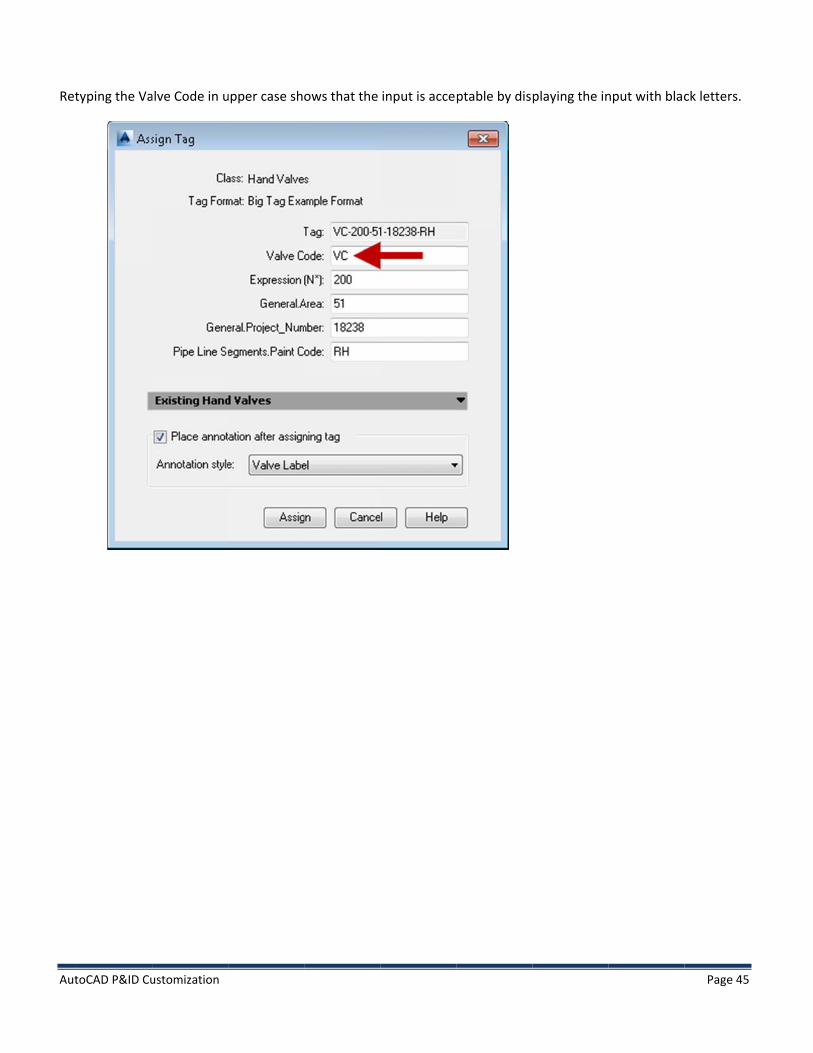
Ret
toCAD P&ID Cu
typing the Va
ustomization
alve Code in uupper case shows that the input is acceptable by dis
playing the innput with blac
Page 45
ck letters.
Aut
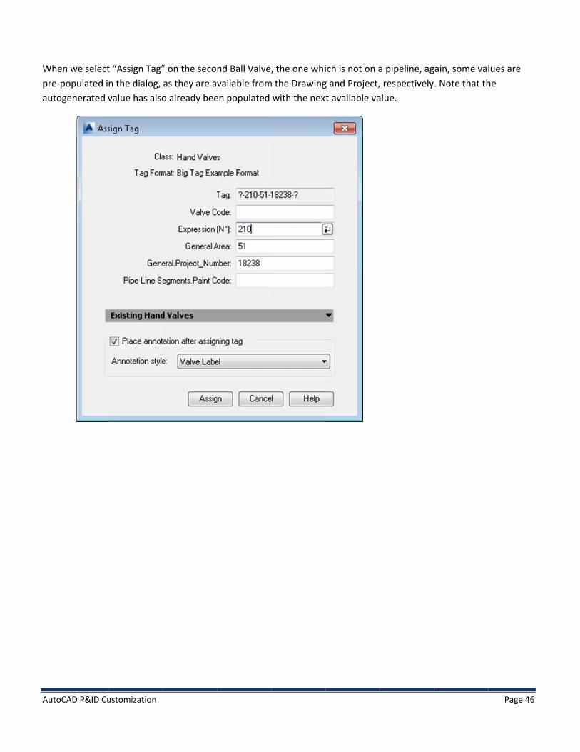
Whpreaut
toCAD P&ID Cu
hen we selecte-populated itogenerated v
ustomization
t “Assign Tag”n the dialog, value has also
” on the secoas they are ao already bee
nd Ball Valve,vailable from
en populated
, the one whim the Drawing
with the next
ich is not on ag and Project,t available va
a pipeline, ag, respectivelyalue.
gain, some val. Note that th
Page 46
lues are he

Aut
Theassthe
For
Thewh
toCAD P&ID Cu
e image belowsociated with e next section
r one final exa
e Tag Formathich is a pure
ustomization
w shows assigany line, fillin
n.
ample, let’s e
shown belownumeric expr
gnments beinng in the Pain
examine a Tag
w has one proression.
ng made to thnt Code value
g Format that
operty subpar
he remaining doesn’t reall
t utilizes the s
rt that will alw
subparts. Sinly have any m
simple variati
ways contain
nce this Ball Vmeaning. We’
ion of autoge
a known valu
Valve is not acll explore tha
eneration.
ue, and one s
Page 47
ctually at more in
subpart

Aut
Wh
toCAD P&ID Cu
hen assigning
ustomization
g this tag, the
numeric subppart shows up with the inccrement arro
ow.
Page 48

Aut
Pre
Thiarrbe tha
toCAD P&ID Cu
essing the inc
is type of autrow will not cthe first avai
at the increm
ustomization
rement arrow
o-generationhange the valable unique ent button is
w produces th
is designed tlue of the nuvalue, which not function
he first nume
to find the firsmeric expreswill be the saing.
ric value that
st available usion. Every ti
ame. It is help
t would result
nique tag. Reme you press
pful to be awa
t in a unique
epeatedly pres the button, are of this, ot
tag value.
essing the incthe result ret
therwise it m
Page 49
rement turned will ight seem

Aut
G.
Eacsecbehcla
Wha Pava
Theass
toCAD P&ID Cu
. Tagging
ch P&ID Classction on custohavioral propss.
hile most aspeP&ID class’s Gailable in the
e value “Promset of this typ
ustomization
Prompt
s Definition spom symbols.) perties are als
ects of the Taraphical Styleright click me
mpt for tag dupe is placed in
Behavior
pecifies one oIn addition to
so defined. On
ag are definede is set to “Noenu for assets
uring componn the drawing
rs and the
or more Grapo the symbolne of these in
d using the Taot a Tagged Cs of that type
nent creation”.
e Graphic
hical Styles. (ic properties
nvolves the pr
ag Format as Component”,
.
” will cause th
cal Style
These will bedefined by th
rompting beh
described sothen the “Ass
he “Assign Ta
e covered in mhe Graphical havior for Tag
far, if the Tasign Tag” opt
ag” dialog to b
more depth inStyle, severa
gs for that spe
gging Prompttion will not b
be raised eac
Page 50
n the l ecific P&ID
t setting in be
h time an

Aut
Thein tdef
H.Oneacpre
In aPRO
OuSincom
In obe
Chaand
toCAD P&ID Cu
e value “Autothe Tag propefined, this ma
. How Tagce the Assignch sub part wevious section
addition, all tOPERTY of th
r second subnce these valumbined string
order to keeprebuilt from
• Changin• Changin
anges to Drawd Project valu
ustomization
omatically asserty by filling ay or may not
gs are Ston button on th
which refers ton.
he subparts ae asset. This
part was a puues are not bag, in the Tag p
p the Tag propits constituen
ng any class png any class p
wing and Projues, once assi
sign an auto-gin all known
t produce a co
ored he Tag Assigno a class prop
and delimiteris shown in th
ure expressioased on any pproperty.
perty synchront subparts. T
property of thproperty of a r
ject propertiegned, are ret
generated tagand autogeneomplete Tag.
n dialog has beperty, the indi
rs are concatehe data grid i
n, assigned 2property, the
onized with thThese include
e tagged asserelated item t
es used in thetained in the c
g” will not raieratable subp
een pressed, ividual value
enated togethmage below.
00 for the firsONLY place w
he underlyinge:
et that is used b
e Tag Format completed ta
se the “Assigparts. Depend
there are twis assigned ba
her and store
st Ball Valve awhere they ar
g properties,
by the tagged
do not automag, even if tho
gn Tag” dialogding upon ho
wo types of stoack to that pr
ed as a single
and 210 for tre stored is as
many activiti
asset
matically rebuose propertie
g, but will atteow the Tag Fo
orage which oroperty, as se
string in the T
he second Bas part of this
es will cause
uild the Tag. Ds are later ch
Page 51
empt to fill rmat is
occur. For een in the
Tag
all Valve. fully
the Tag to
Drawing anged at

Aut
thecla
Exa
In tsubPipthe
toCAD P&ID Cu
e Drawing or ss-property s
amples:
this example,bpart value chpeLine.PaintCe initial assign
ustomization
Project level.subparts are i
, I modify thehanges to a ‘?ode, this valu
nment, but th
In other worncorporated.
second Ball V?’. Since this Bue is actually he fully forme
rds, when the.
Valve by assigBall Valve is nblank. In poin
ed string from
e tag property
gning GE as thnot situated ont of fact, it sh
m the Tag Assi
y is rebuilt fro
he manufactuon a PipeLine,houldn’t havegn dialog is a
om subparts,
urer. Notice t, and the Tag e shown the Lalways assigne
only changes
hat the PaintFormat spec
LTX value eveed at first.
Page 52
s to
tCode ified
en after
Aut
In tNo
Youopedel
I. The
Dube hav
Notagreje
Foruninotnoz
toCAD P&ID Cu
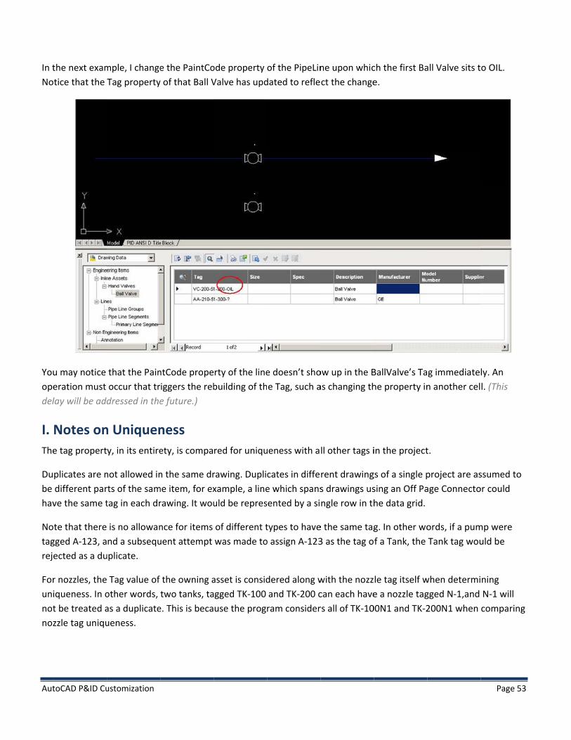
the next examtice that the
u may notice eration must lay will be add
Notes one tag propert
plicates are ndifferent par
ve the same t
te that theregged A-123, aected as a du
r nozzles, theiqueness. In ot be treated azzle tag uniqu
ustomization
mple, I changeTag property
that the Painoccur that trdressed in the
n Uniqueny, in its entire
not allowed inrts of the samtag in each dr
is no allowannd a subsequ
uplicate.
Tag value of other words, as a duplicateueness.
e the PaintCoy of that Ball V
ntCode propeiggers the rebe future.)
ness ety, is compa
n the same drme item, for ex
rawing. It wou
nce for items uent attempt
the owning atwo tanks, ta
e. This is beca
ode property Valve has upd
rty of the linebuilding of th
red for uniqu
rawing. Duplixample, a lineuld be repres
of different twas made to
asset is considagged TK-100 use the prog
of the PipeLindated to refle
e doesn’t shoe Tag, such a
ueness with a
cates in diffee which spansented by a si
types to haveo assign A-123
dered along wand TK-200 cram consider
ne upon whicct the change
ow up in the Bas changing th
ll other tags i
rent drawings drawings usngle row in th
e the same tag3 as the tag o
with the nozzcan each havers all of TK-10
ch the first Bae.
BallValve’s Tahe property in
in the project
gs of a single psing an Off Pahe data grid.
g. In other wof a Tank, the
le tag itself we a nozzle tag
00N1 and TK-2
all Valve sits t
g immediaten another cel
t.
project are asage Connecto
ords, if a pumTank tag wou
when determigged N-1,and 200N1 when
Page 53
o OIL.
ly. An l. (This
ssumed to or could
mp were uld be
ning N-1 will comparing

AutoCAD P&ID Customization Page 54
J. Tag Behavior during Cloning “Cloning” refers to any operation that places a copy of an AutoCAD entity into a drawing. Examples of cloning include the COPY, ARRAY, and MIRROR commands, Clipboard Copy/Paste (Ctrl-C/Ctrl-V), BLOCK, WBLOCK, INSERT and EXPLODE.
Since AutoCAD P&ID is a project-based product, copying a tagged asset within a single drawing or between drawings belonging to the same project would tend to create duplicate tags, which would be rejected.
To avoid this duplication and rejection, the product will blank out both the Tag property, and all the class property subparts which contribute to the tag. Blanking out the subparts is necessary because automatic tag regeneration would simply rebuild the duplicate tag if the subparts were left intact.
K. Pitfalls and Workarounds There are a number of operations which will parse the tag back down into its constituent sub parts. One example is any operation that presents the sub parts to you for editing. For example, raising the Assign Tag dialog on an asset that is already tagged (for example to modify the Tag property) presents all the sub parts in each edit box. Another example is the operation which rebuilds the tag from its subparts whenever one of those subparts has been changed.
To do this, it has to parse the combined Tag property back down into its constituent parts. It has several ways of distinguishing between the subparts. One is to compare against the delimiters. Another is to re-retrieve the property from its original storage and compare the strings.
However, if pure expressions are placed without any delimiter, then it cannot determine where one sub part ended and the next begins.
If your Tag Format requires that there be subparts which are not delimited, you may need to add a new property to hold each subpart.
This is important as any refresh of the Tag could result in the loss of the pure expression portions of the Tag.

Aut
In tdel
toCAD P&ID Cu
the followinglimiter.
a Tag baData Gr
ustomization
example, the
ased on this Trid. “C3333”
e Tag Format
Tag Format is
is defined wi
being assign
ith a Property
ed. The conca
y and a pure n
atenated, un-
numeric expr
-delimited Ta
ression, but n
ag can be seen
Page 55
o
Here, n in the

Aut
Re-
In tdoi
toCAD P&ID Cu
-raising the T
the example ing so, the pu
ustomization
ag Assign dia
below, assignure expression
log illustrates
ning a new prn portion of t
s that the pur
operty to onethe Tag has be
re-expression
e of the asseteen lost.
n subpart has
t’s fields has c
not been suc
caused the Ta
ccessfully par
ag to be recal
Page 56
rsed.
culated. In

Aut
If ypro
L. Linareindcuradd
V.Anbehbei
Antha
A.Simann(fo
toCAD P&ID Cu
you must haveoperties in Au
Special Be Segments a
e compared fodividual Line Srrent release.d additional p
. Annotnotations arehaviors that aing annotated
notations utiat should be s
. Simple Ample Annotatnotations arent, size, etc.)
ustomization
e un-delimiteutoCAD P&ID
Behavior are collected or uniquenesSegment. In a. A future releproperties to
tation Se implementeallow the actud. We call the
lize the sameshown.
Annotatioions are creat
e not based onare based on
ed subparts, tis straightfor
for Line Sinto Line Gros. In AutoCADddition, it is o
ease will expothe Line Grou
Styles ed as regular Aual textual vae item being a
e mechanism
ons ted by draggin any annotan the current
hen those surward, and ca
Segment oups. This leadD P&ID, it is aonly the “Lineose a Tag proup Tag.
AutoCAD Bloclues shown to
annotated the
as the Tag Fo
ng and dropption style, areAutoCAD sett
bparts shouldn be accomp
Tag Uniqds to special bctually the Li
e Number” prperty on the
ck Referenceo be dynamice “target”.
ormats, with a
ping a Data Ge created usintings for text
d always be blished from t
queness behavior withne Group tharoperty of theLine Group d
s and Text encally evaluate
a few minor d
rid cell onto tng AutoCAD t.
based on a prohe Project Se
h respect to hat is tested foe Line Group irectly via the
ntities, with soed based on p
differences, to
the drawing ptext entities,
operty. Addinettings dialog
how Line Segmor uniqueness
which is testee UI, so that u
ome additionproperties of t
o specify the
pane. These and the text
Page 57
ng .
ment tags s, not each ed in the users can
nal the item
property
properties

Aut
Beh“Pr
B.Coa n
Ancan
Anbeh
AnSet
toCAD P&ID Cu
hind the scenroperty” is th
Compoumpound Ann
new Annotatio
notation Styln be used to a
notation Stylhavior.
notation Stylttings dialog f
ustomization
nes, a simple ae property sp
und Annootations provon Style has s
es are defineannotate any
es are also as
es are manipfor Annotatio
annotation Tepecified by th
otations vide a great dsimilarities to
d at a given ctarget P&ID
ssociated with
ulated from ton Styles.
ext entity care Data Grid c
deal more flex both Tag For
class level in tentity define
h an AutoCAD
the Project Se
rries the Formcolumn from w
xibility and curmat creation
the P&ID Clasd at or below
D Block Defini
ettings dialog
mat String “Tawhich the cel
ustomizabilityn and creation
ss Definition hw that node in
ition, which p
g. Pressing “Ed
argetObject.Pll was selecte
y than Simplen of a Symbo
hierarchy. Onn the hierarch
provides for t
dit Annotatio
Property,” whed.
Annotationsl for a P&ID o
ce defined, thy.
heir appeara
n” raises the
Page 58
ere
. Creating object.
hat style
nce and
Symbol

Aut
“Syrigh
“BlSymthe
toCAD P&ID Cu
ymbol Name”ht-click/Anno
ock” is the nambol Name pe more button
ustomization
” is the name otate… contex
ame of the blpost-pended wn.
of the Annotxt menu item
ock definitionwith “_block.”
tation Style. T is selected.
n upon which” To select a d
This is the nam
h this Annotatdifferent bloc
me that appe
tion Style is bck definition,
ars in the sub
based. The naselect the Blo
bmenu when
me is always ock edit box,
Page 59
the
the and press

AutoCAD P&ID Customization Page 60
Doing so will raise a three-step navigation dialog allowing you to choose a drawing, and a block within that drawing, and alter settings for the annotation to use for the Annotation Style. Once you have selected the block definition, the contents of that block definition will be cloned into your ProjSymbolStyle.dwg and renamed to SymbolName_block.
AutoCAD P&ID ships with a file called AnnotationTemplates.dwg. This drawing file contains a number of block definitions that may be useful as templates for a variety of standard annotation styles, and for which the more complex settings (the dynamic sizing settings) are already in place.
The “General Style Properties” are the standard AutoCAD entity properties, such as color, layer, and linetype that will be used when the annotation (an AutoCAD block reference) is created and inserted into the drawing.
The “Other Properties” area of the dialog offer settings that are specific to Annotations.
• “Symbol Scale” is a scale factor at which the annotation will be inserted into the drawing. • “Use Target Properties” will cause the annotation to be inserted with the same entity properties (color,
layer, linetype) as the target entity, rather than using the settings from “General Style Properties.” • “Linked” controls whether the annotation moves along with the target entity. • “Auto Insert” controls whether the annotation will be automatically inserted when the target entity is
inserted into the drawing.
“Auto Insert?” has three possible states, worthy of further discussion.
“No Auto Insert” is self explanatory. Annotations based on this style will never be automatically inserted into the drawing.
The other two settings are primarily meaningful for the default Annotation Style for a given P&ID class, and take effect when placing an asset of that class into the drawing from the tool palette.
“Auto Insert With Prompt” --If an asset is placed in the drawing whose default Annotation Style specifies Auto Insert With Prompt, the user will be automatically prompted to select a position for the annotation.
“Auto Insert” --If an asset is placed in the drawing whose default Annotation Style specified Auto Insert, then the annotation will automatically be placed in the drawing at the positions specified by “Offset X” and “Offset Y” from the asset’s insertion point.
The Offset X and Offset Y settings are only enabled when the Auto Insert state is Auto Insert.
Note that the Auto Insert option, relying on the Offset X and Offset Y settings, does not work when the target is a pipe or signal line. The reason is that the software cannot determine a single insertion point from which to calculate the offset from a line, as it can do from an asset.
“Auto Insert” using an offset will also have an effect when placing an annotation via the right click “Annotate” menu. Normally, when using the Annotate… context menu, you would be prompted to select a position using the mouse. However, when annotating an asset using an annotation style which specifies “Auto Insert” with an X,Y offset, the annotation will be placed at that offset.

Aut
Use
Ori
C.In tbutsel
toCAD P&ID Cu
e leader indic
ientation cha
Creatingthis example,tton, and theect “Annotat
ustomization
cates whethe
nges how the
g a New A, a new Annotn pressing thionTemplates
r a leader wil
e annotation
Annotatiotation Style ae more buttos.dwg” and p
l be included
is rotated.
on Style t the Hand Va
on beside theress “Open.”
with the ann
alves level wiBlock proper
notation.
ill be created rty, as describ
by pressing tbed above. In
the “Add Annn the navigatio
Page 61
notation” on dialog,

Aut
In tAn
No“Infis p
toCAD P&ID Cu
the “Select Blnotation Styl
te: See the senfoTag2LineBoplaced.
ustomization
lock” dialog, se.
ection ‘Linear ox” block defi
select “InfoTa
Parameters iinition that yo
ag2LineBox” a
in Annotationou will need t
as the block d
n Block Definito make to ge
definition upo
itions’ for subet the best po
on which we’
btle improvemossible results
ll base the ne
ments to the as when this an
Page 62
ew
as-shipped nnotation

Aut
He
Pre
Evebutbe
toCAD P&ID Cu
re, the annot
ess OK. This w
ery Annotatiot Annotation unique to tha
ustomization
tation is given
will copy the b
on Style pointStyles do notat Annotation
n the name “V
block definitio
ts to a uniquet, because then Style.
Valve InfoTag
on into Projec
e block definite Attribute De
g” and the des
ctSymbolStyle
tion. Graphicaefinitions for
sired settings
e.dwg and re
al Styles (“Symeach Annota
s are made to
name it to “V
mbols”) may ation Style ne
o the Style pro
ValveInfoTag_
share block ded to be set u
Page 63
operties.
_block”.
definitions, up so as to

Aut
D.Preset
toCAD P&ID Cu
. Assigninessing the “Edt up for this se
ustomization
ng Formadit Block” butection, select
t Strings tton allows edt our new Ann
to Attribditing of the Bnotation Style
ute DefinBlock Definitioe, “Valve Info
nitions on upon whic
oTag” from thch the Annotae picklist and
ation Style is d press “Edit B
Page 64
based. To Block…”

Aut
Thi
temgeolinenexthe
To
Noobj
toCAD P&ID Cu
is operation w
mplate contaiometry; an unear parametext section. The line, each of
fix an action,
tice that the ject that need
ustomization
will drop you
ins two Attribnderline beneers, each assohe block may f the attribute
, right click on
action as a dods to stretch
into the Auto
bute Definitioeath UNASSIGociated with ahave several es and the re
n the action ic
otted windowis selected.
oCAD block ed
ons, named UGNED1, and aa pair of stretcduplicates dictangle).
con, select Ac
w associated w
ditor for the A
NASSIGNED1 box around ch actions. Wrectly on top
ction Selectio
with it. Re-c
Annotation St
1 and UNASSIGboth Attribut
We’ll discuss th of each othe
on Set, and th
create the str
tyle’s block d
GNED2. It alste Definitionshe geometry
er (4 duplicate
en Modify Se
retch window
definition.
To contains so
s. Finally, it coand paramet
es should be e
election Set.
w, and make s
Page 65
This ome ontains 3 ters in the erased for
sure the

Aut
Rep
toCAD P&ID Cu
peat the proc
ustomization
cess for all of the actions.
Page 66

Aut
Theentwilandpro
Whfirsall.add
UsiAtt
AftNo
toCAD P&ID Cu
ese Attributetity. Pressing l then raise thd lets you setoperties of th
hen this dialost delimiter. Any kind of fditional text a
ing the same tribute Defini
ter pressing Otice that the
ustomization
Definitions cthe icon in thhe Assign Annt up the Attribe Project.
g is first raiseIn fact, for A
free text is alappearing wh
skills discussetion, and rem
OK, the value linear param
currently are nhe small toolbnotation Formbute Definitio
ed for an UNAAnnotation Folowable. Rem
hen the annot
ed in definingmove the wor
of the UNASSeter named U
not set up to bar will prommat dialog. Thon to display p
ASSIGNED Attormats, the a
member to remtation is place
g a Tag Formad UNASSIGNE
SIGNED1 AttrUNASSIGNED
display any ppt you to selehis dialog is exproperties of
ribute Definitrea between move or chaned in the draw
at, we’ll assigED1 from the
ibute Definiti1 has been ed
particular proect an Attribuxtremely simthe target en
tion, the worsubparts nee
nge this delimwing.
gn the target oe delimiter fie
ion has been dited in the s
operties of anute Definitionilar to the As
ntity, propert
rd “UNASSIGNedn’t be thou
miter value if y
object’s Tag peld.
changed to #ame way. We
Annotation’sn. Making that
sign Tag Formties of the Dra
NED1” appearught of as a deyou don’t wa
property to th
#(TargetObjece’ll discuss wh
Page 67
s target t selection
mat dialog, awing, or
rs as the elimiter at nt any
he first
ct.Tag). hy this is

Aut
impThi
Eaconeupo
toCAD P&ID Cu
portant in theis is an AutoC
ch Attribute De property. Won which the
ustomization
e next sectionCAD artifact.
Definition shoWe’ll define th
Valve sits. Th
n. You may ha
ould be used the second subhe following p
ave to execut
to place a sinbpart to showproperties an
te BSAVE in or
gle line of texw two propert
d delimiters y
rder to see th
xt, but each lties, one fromyield the form
he linear para
ine of text mam the Valve, amat string as s
meter label c
ay present mand one fromshown below
Page 68
change.
ore than the Line
w.
Aut
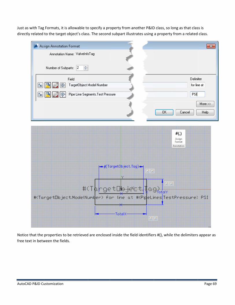
Jusdir
Nofre
toCAD P&ID Cu
st as with Tagectly related
tice that the e text in betw
ustomization
Formats, it isto the target
properties toween the field
s allowable toobject’s clas
o be retrievedds.
o specify a pros. The second
d are enclosed
operty from ad subpart illus
d inside the fi
another P&IDstrates using
ield identifier
D class, so lona property fr
rs #(), while th
ng as that clasrom a related
he delimiters
Page 69
ss is class.
s appear as

Aut
It isFiethethe
Clo
toCAD P&ID Cu
s also possibleld, and set the Attribute Dee free text “M
ose and save t
ustomization
e to have leahe delimiter oefinition in th
Model No.” is
the changes t
ding text. Youon the first bla
e AutoCAD ppre-pended.
to the block, a
u can add leaank item. Theroperties pal
and OK out o
ding text by oe rest of the fiette, and pre
f the Project
one of two mields get filled
e-pend the fre
Settings dialo
methods. Startd out normalee text you w
og.
t off with an aly. You can al
want. In this ex
Page 70
additional lso select xample,

Aut
NoVal
toCAD P&ID Cu
w, let’s use tlve on that lin
ustomization
his annotatione and assign
on. Create a P the tag value
ipe Line and ae of GV-001, a
assign a Test and a model
Pressure of 2number of 81
250 using the10.
Data Grid. Pl
Page 71
lace a Gate

Aut
Sel“Va
TheDefthe
1. It isdef
toCAD P&ID Cu
ect the Gate alve InfoTag”
e Attribute Dfinition has re
e text, both th
Using Expres possible to fine another,
ustomization
Valve, right cstyle that we
efinition for #eplaced #(Tarhe leading tex
essions in Anuse the Expresimple Anno
click and selece have just de
#(TargetObjecrgetObject.Mxt and those p
nnotation Foessions portiotation Style.
ct Annotate…efined.
ct.Tag) collecodelNumberplaced using t
ormat Stringon of the Assi
… from the con
ted the targe) with 810 anthe delimiter
gs gn Annotatio
ntext menu. F
et object’s tagnd #(PipeLinesr boxes, appe
on Format dia
From the sub
g value. The ss.TestPressurars unchange
alog to enforc
bmenu, select
second Attribre) with 250. ed.
ce formatting
Page 72
t the
ute The rest of
. Let’s

Aut
UsiAnsho
The
Theexpenfexpstr
Ouplama
It isStrAnnstoanyWh
toCAD P&ID Cu
ing the same notation Formould be uppe
e resulting fo
e main differepression is usforce input. Wpression is using field, to se
r Gate Valve ace the annotanufacturer h
s possible to uring so long asnotations REA
ore the result y autogenerahile possible,
ustomization
techniques amat. The firstr cased, any a
rmat string a
ence betweened for Taggin
When the exped to format eparate the p
already has aation. Noticeas been uppe
use the Autogs you do so inAD data, theyONLY in the a
ated expressiothis usage is n
as for create Tt subpart specamount of ch
ppears as fol
n using an exng (which is thpression is use
output. The property bein
a model numb how the num
er cased.
generation pon combinationy do not creatannotation itsons so that thnot recomme
Tag Formats, cifies 5 numearacters.
lows:
pression in a he act of creaed as part of Apercent sign g read from t
ber of 810. Wmber has bee
ortion of the Dn with a pure te data, so usself, and not iey do not con
ended.
expressions hrals, and the
Tag Format vting and storAnnotation (wappears as a the formattin
We will add “Bn pre-pended
Define Expresexpression, a
sing an autogin any underlyntinue to incre
have been apsecond subp
vs. an Annotaring data), thewhich reads asymbol after
ng being requ
Bosch” in mixed with zeros t
ssion dialog wand not with aenerated expying storage.ement with e
pplied to bothart specifies t
ation Format e expression iand displays e the propertyested.
ed-case as thto make it 5 d
when creatinga property. Re
pression as pa AutoCAD P&
every refresh o
h the subpartsthat the prop
is that when is used to valexisting data)y, but inside t
e manufacturdigits long, an
g an Annotatiemember tha
art of an Anno&ID will pre-evof the Annota
Page 73
s of this perty
the idate and ) the the format
rer, and nd the
on Format at otation will valuate ation.

Aut
In t
Theshodotass
Anyto
If a
ThediffThe
toCAD P&ID Cu
the image ab
e default Annowing #(Target. Whenever sign a size val
y modificatiorefresh autom
an annotation
e most commferent drawinen choose the
ustomization
ove, notice th
notation StyleetObject.Sizethe annotatioue to the Gat
on to a class pmatically. The
n becomes dis
mon way to cang. To re-assoe object the a
he small dot a
e for Hand Va). Because thon cannot rette Valve, the d
property of the refresh butt
sconnected fr
ause such an oociate the annannotation sh
above the Ga
lves is “Valveere is no size
trieve a specifdot will upda
e target or thton on the Da
rom its target
occurrence isnotation, selehould use to r
te Valve.
Label”, whic assigned to tfic property, ite to show th
he class propeata Grid will a
t entity, all th
s to copy an aect it, right-cliread properti
ch is defined athe Gate Valvit shows that
hat size.
erty of a relatlso refresh al
he properties
annotation byick and then ces.
as a single Attve, the annot property as a
ted asset will ll the annotat
show the str
y itself, and thchoose Assign
tribute Definiation shows ua dot. As soo
cause the antions in the d
ing “No Targe
hen paste it inn Annotation
Page 74
ition up as a n as we
nnotations rawing.
et”.
nto a Target.

Aut
TheMapro
AutthiswainsValwilbes
Thedef
2. On
Do
toCAD P&ID Cu
e shortcut noany P&ID clasoperty.
toCAD P&ID ps tool, one cas #(GateValvtead show thlve. It recognl be retrievedst possible su
e main thingfinition are a
Using Annotce an annota
uble clicking
ustomization
omenclature Tses in the sam
provides a vean easily conve.Size). Upon
he dot. The reizes the classd for any targupport for ma
g to remembalways used
tations to Edation has been
our Valve Inf
TargetObject me family hav
ry simple mevert a Gate Va substitution
eason for this mismatch, aet entity thatintaining ann
er about Anto retrieve a
dit Underlyin placed, dou
oTag annotat
is particularlyve the same p
ethod to substalve into a Bato a Ball Valvis that it is trnd fails to rett has a Size prnotation integ
notations isand display e
ng Data uble clicking o
tion yields the
y useful for Aproperties. Fo
titute relatedll Valve. Now
ve, your annoying to retrieturn any dataroperty. Thusgrity in conjun
that the Forexisting data
on that annot
e following di
Annotations, eor example, a
d P&ID objectw consider if totation wouldeve a GateVala. However, bs, the TargetOnction with th
rmat Strings a, never to as
tation brings u
ialog.
even more soall Hand Valve
s; the substithe Annotatio
d cease showive property,
by using #(TarObject nomenhe substitutio
in an Annotassign data to
up a special e
o than for Tages have the Si
tution paletteon for the Gating the size anspecifically, f
rgetObject.Siznclature provion palette.
ation Style’s o storage.
editor.
Page 75
g Formats. ze
e. Using te Valve nd would from a Ball ze), data ides the
block

AutoCAD P&ID Customization Page 76
Recall that the first line of this annotation style was based on the format string #(TargetObject.Tag), and that Tags are themselves built up of subparts as defined in the Tag Format.
The first line of this editor utilizes the Tag Format to break TargetObject.Tag back into its constituent parts and present those parts for editing.
The second line of this editor directly uses the Annotation Format String to present each part for modification.
Modifications made in this UI are stored in different locations. All PROPERTY changes to the target object’s properties are actually stored directly back to the underlying storage in the datacache. (Drawing and Project properties cannot be modified from this dialog.) The changes seen in the annotation are a result of the annotation refreshing after these values have been changed in their original location.
Modifications to the delimiters are stored in the Annotation itself, and affect ONLY the annotation being edited, not ALL annotations.
Although it would be odd to use pure expressions in an Annotation Format String, nothing prevents you from doing so. Be aware, however, that if you use pure expressions without any delimiters in an Annotation Format String, the program will have the same problem reparsing the annotation into its subparts as it has when parsing Tags, and you may get unexpected results in the Edit Annotation dialog.
3. Special Behaviors --Reducer Annotation Styles AutoCAD P&ID ships with 4 standard annotation styles for Reducers:
• Fixed Reducer Style • Large by Small Reducer Style • Flow Based Reducer Style • Adjacent Pipe Reducer Style
The first of these is based on the properties of the reducer itself. The Annotation Format String for Fixed Reducer Style is: #(TargetObject.Size1)x#(TargetObject.Size2).
The other three styles are “Pipe Based” reducer styles, and AutoCAD P&ID applies special rules when evaluating the format string, which is the same in all three styles: #(PipeLines.Size)x#(PipeLines.Size).
For these special Annotation Styles, even though the same property appears twice in the format string, the program will collect the sizes from the two separate pipelines attached on each side of the reducer. It will then calculate, based on the name of the reducer style, which size value should be shown first.
• Large by Small Reducer Style --Shows larger size value first always. • Flow Based Reducer Style --Shows the size value of the incoming pipe first. • Adjacent Pipe Reducer Style --Shows the size values on each side for the pipe on that side.
Users may create other pipe based reducer styles that show additional data. In order for it to recognize such styles and apply the special processing, the following must be true:
• The Annotation Style must be defined at the Reducers level in the class hierarchy • The Annotation’s target must be a Reducer.

AutoCAD P&ID Customization Page 77
• The Annotation Style’s name must begin with: o Large By Small Reducer o Flow Based Reducer o Adjacent Pipe Reducer
• The Format string must contain exactly one delimiter • The Format string must contain a property #(PipeLines.Property) on each side of the delimiter. • The Format string may contain other properties, as long as the properties on each side of the delimiter are
identical and in the same order.
It is not recommended to use the Edit Annotation dialog to modify the values of Pipe Based Reducer annotations, as this dialog cannot distinguish to which pipeline the new size value should be assigned.
E. Principles of Dynamic Sizing In the Annotation examples above, several geometric items dynamically changed size to match the evaluated values of the attributes. When the “Valve InfoTag” Annotation Style was placed in the drawing, the underline under GV-100 matched the width of the text, and the box fit nicely around all of the evaluated text.
AutoCAD P&ID leverages the AutoCAD “Dynamic Block” feature in custom ways to enable this behavior. Dynamic block definitions are defined in such a way that each block reference (aka insert) of that block can be independently manipulated in ways that change its appearance, for specific sub portions of the block.
The AutoCAD Dynamic Block feature is extensive and will not be covered in depth here, but it is recommended that interested users spend some time studying the documentation and/or taking an AU course on this feature. Authoring a dynamic block has nearly as much power and potential complexity as writing computer code!
1. A brief overview of Dynamic Block Principles Creating a Dynamic Block Definition in AutoCAD involves placing and defining several items in the block definition which are not geometry. These items are known as “parameters” and “actions”.
There are a variety of different types of parameters, each of which track some set of properties, for example:
• Linear parameters have a length • Rotational parameters have a rotation. • Point Parameters have a position.
Each parameter can be associated with one or several types of actions. Typical actions include: • Stretch • Move • Rotate • Flip
Each action is associated with an “action frame”, which indicates which geometry within the block definition participates in the action, and in what fashion. The available actions may be presented to the user as a special grip on the block insert, or the grips may be hidden from the user, depending upon whether the block author intends.

Aut
Forwitlineline
ThePar
2. In tAttlabeva
In o
In tGVlen
Letthepre
toCAD P&ID Cu
r each block ith a single Linear parameteear paramete
e list above isrameters, so t
Linear Paramtruth, AutoCAtribute Definibel is identicaaluated, it wil
other words:
the block defV-001 in the bngth equal to
t’s look at a sie Engineeringess the Edit B
ustomization
nsert, the pronear Parameteer may be differ will yield di
s by no meansthe remainde
meters in AnAD P&ID maktion caries anl to the Attribll set the linea
inition you mlock referencthe six chara
imple examplg Items node ilock button.
operties tracker may be insferent in eachifferent result
s exhaustive. er of the discu
nnotation Bes only a sligh
n annotation bute Definitioar parameter
may have a force, 6 charactecters.
le, the “Oval Tin the P&ID O
ked by the paserted into anh block insertts.
The AutoCADussion will foc
lock Definitiht tweak to thFormat String
on, then in ear to be the sam
rmat string #(ers long. In th
Tag Style” AnObjects Defini
rameter mayn AutoCAD dr. Depending u
D P&ID Annotcus on those.
ions he behavior og. If the blockch block referme width as t
(TargetObjecte block refere
nnotation Styltions class hie
y have differerawing multipupon that len
tation feature.
of Linear Parak definition alrence, after tthe evaluated
t.Tag), 19 chaence, the line
le. Using the erarchy, selec
ent values. A sple times, andngth, actions
e extends the
ameters. It reso carries a lihe format str
d value.
aracters long,ear parameter
skills discussect the Oval A
single block dd the length oassociated w
e behavior of
cognizes wheinear paramering has been
but which ber will be set t
ed above, navnnotation Sty
Page 78
definition of the ith the
Linear
en an eter whose n
ecomes o the
vigate to yle, and

Aut
TheDef#(T
Seland
For
In tlineThe
For
Theova
toCAD P&ID Cu
e block editorfinition carry
TargetObject.
ecting the strd the geomet
r stretch actio
• Entities • Entities
moved. • Entities
the example aear parametee line segmen
r completene
e right hand sal.
ustomization
r shows an oving the #(TargTag) format s
retch action otry which is p
ons, the rules
which are nowhich are se
which are seabove, the ar
er moves righnts at the top
ess, we highlig
stretch action
val shaped piegetObject.Tagstring. The Lin
on the left higarticipating in
s are as follow
ot selected byelected by the
elected by therc on the left t or left (depe and bottom
ght the other
n also selects
ece of geomeg) format strinear Paramet
ghlights the stn the action. A
ws:
y the action ae action and a
e action and wside of the ovending upon of the oval cr
stretch actio
the top and b
etry consistingng, and a Line
ter is associat
tretch action A small recta
re not modifiare completel
which cross thval is complethow the overross the linea
on as well.
bottom lines,
g of line and ear Parameteted with two
itself, the pangle shows th
ied ly inside or co
he frame are tely inside therall linear par
ar parameter,
but selects t
arc segmentser also carryinstretch action
arameter withhe “action fra
ompletely out
stretched. e frame, so wrameter is siz, so they will s
the arc on the
s, an Attributeng the ns.
h which it is aame” for this
tside the fram
when the left ed) the arc wstretch.
e right hand s
Page 79
e
ssociated, action.
me are
side of the will move.
side of the

AutoCAD P&ID Customization Page 80
Selecting the linear parameter itself and raising the properties palette shows some special settings specific to the linear parameter.
Notice that the endpoints of the linear parameter are actually slightly inside the edges of the geometry, rather than directly on the edges. Doing this ensures that there will be some space around the text when the stretch actions are applied. If the linear parameter were exactly on the edges of the geometry, then when the parameter is sized to match the attribute’s width, the geometry will exactly enclose the attribute, which usually doesn’t look very good.
Note: The InfoTag2LineBox block definition in AnnotationTemplates.dwg used in part C., “Creating a New Annotation Style” actually shipped with this very problem. To get the best results, you may need to adjust the end points of the linear parameters to be inside the box, and assure that the Base Location property on each is “midpoint”, as discussed below.

Aut
Thethecan
Theparancres
toCAD P&ID Cu
e property caese values even use the pro
e linear paramrameter will bchor for the lsults in the ge
ustomization
alled “Distancer fail to matcperty palette
meter’s Base be anchored ainear parame
eometry cont
e Label” is thch, then the l to fix such er
Location proas its size is c
eter, and centrolled by the
e property thinear paramerrors, should
perty can be hanged. In mter-justify thelinear param
hat must matceter will not bthey occur.
start point omost of our she Attribute Deeter staying c
ch the Attribube associated
r midpoint, aipping annot
efinition at thcentered on t
ute Definitiond with the Att
nd indicates ation templat
he same X Valthe attribute.
n’s format strribute Definit
how the lineates, we use alue. This com.
Page 81
ring. If tion. You
ar midpoint bination
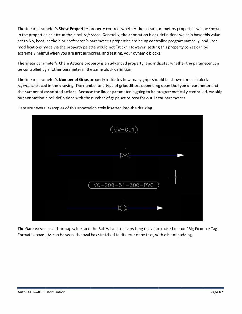
Aut
Thein tsetmoext
Thebe
Thereftheour
He
TheFor
toCAD P&ID Cu
e linear paramthe propertiet to No, becauodifications mtremely helpf
e linear paramcontrolled by
e linear paramference placede number of ar annotation
re are severa
e Gate Valve rmat” above.
ustomization
meter’s Showes palette of tuse the block
made via the pful when you
meter’s Chainy another par
meter’s Numbd in the drawassociated actblock definiti
l examples of
has a short ta) As can be se
w Properties phe block refereference’s p
property paleare first auth
n Actions prorameter in the
ber of Grips pwing. The num
tions. Becausons with the
f this annotat
ag value, and een, the oval
property contrence. Gener
parameter’s ptte would no
horing, and te
perty is an ade same block
property indicmber and typese the linear pnumber of gr
tion style inse
the Ball Valvhas stretched
trols whetherrally, the annoproperties aret “stick”. How
esting, your dy
dvanced prop definition.
cates how mae of grips diffeparameter is grips set to zer
erted into the
ve has a very ld to fit aroun
r the linear paotation block e being contrwever, settingynamic block
perty, and ind
any grips shoers dependinggoing to be pro for our line
e drawing.
long tag valued the text, w
arameters pro definitions w
rolled programg this propert
ks.
dicates wheth
uld be showng upon the ty
programmaticear paramete
e (based on oith a bit of pa
operties will we ship have tmmatically, aty to Yes can
her the param
n for each bloype of paramecally controlleers.
our “Big Examadding.
Page 82
be shown this value nd user be
meter can
ock eter and ed, we ship
mple Tag

Aut
Forfor
No“Dithemawid
Dirval
3. TThema
toCAD P&ID Cu
r illustrative pr the two bloc
tice the propistance Label”e value. Whenanual changesdths.
rectly below, ue. Selecting
TotalX and Tere are two satch Attribute
ustomization
purposes, I enck references
perty under th” of your linen you first begs to the width
under the Attthis item and
TotalY pecial names
e Definition’s
nabled the “Sbelow.
he “Custom” har parametergin authoringh of the linear
tributes headd clicking the
s that AutoCAformat string
how Properti
heading caller as the propeg dynamic blor parameter,
ding, you see ellipsis butto
AD P&ID undegs. Let’s revie
ies” setting in
d #(TargetOberty name, anocks, you mayin order to pr
the attributeon will raise th
erstands for liw the block d
n the block de
bject.Tag). In nd the actual y find it helpfureview how y
for #(TargetOhe Edit Annot
near paramedefinition for
efinition, and
this case, youwidth of the
ul to have thiyour actions w
Object.Tag), atation dialog
ters, in additour Valve Inf
show the pro
u are being shlinear params enabled, an
will behave at
and its currenfor that attrib
ion to those nfoTag annotat
Page 83
operties
hown the meter as nd to make t various
nt text bute.
named to tion style.

Aut
No
In aAutrefIf it
Thi
Nowit
V
A.
1. Theeacyouof t
In ctheDef
TheStyits
Onsev
toCAD P&ID Cu
tice the two
addition to ustoCAD P&ID a
ference. If it et encounters
is can be usef
te that TotalXth format stri
I. Custo
. Creating
Block Definiere is a differch Annotationu select a Blothat Block De
contrast, Grae Block Definifinition, and c
e reason thatyle will defineown Block De
the other haveral differen
ustomization
linear parame
sing the widthalso calculateencounters ththe TotalY lin
ful, as in this
X and TotalY wngs.
om Sym
g Custom
ition Managence between Style is alwack Definition
efinition for yo
phical Styles tion for an exchanges to th
t an Annotatioe different Attefinition.
and, Graphicat graphical st
eters named
h of an evaluaes the combinhe TotalX lineanear paramet
example, for
will not collec
mbols
Symbols
gement n how Block ays associatefor an Annotou to modify
are designedxisting Graphhat Block Defi
on Style autotribute Defini
al Styles were tyles for the s
TotalX and To
ated format sned extents ofar parameterer, it sets its s
creating a bo
ct the extents
s
Definitions ard with a uniq
tation Style th.
to share Blocical Style, botinition will aff
matically creations with dif
designed witame P&ID cla
otalY.
string to set tf all the evalur, it sets its sizsize equal to
ox that surrou
s of other tex
re managed fue Block Def
hat already ex
ck Definitionsth the old andfect both Gra
ates a new Blfferent Forma
th the assumpass which diff
the width of auated format ze equal to ththe height of
unds several f
xtual entities
for Annotatioinition. Whenxists, the prod
s. If you creatd new Graphi
aphical Styles.
lock Definitioat Strings, thu
ption that usefer only with
an associatedstrings in the
he width of thf those combi
format string
in the block;
ons vs. Graphin creating a nduct will auto
te a new Grapical Style will .
on is that usuaus each Anno
ers would morespect to th
linear parame entire blockhose combineined extents.
s.
only those as
ical Styles. Bynew Annotatioomatically ma
phical Style anuse that one
ally, each Annotation Style m
ost often wane other style
Page 84
meter, k ed extents.
ssociated
y default, on Style, if ake a copy
nd select Block
notation must have
nt to create

Aut
proacc
2. CGivfirs
UseDefDef
Rem
toCAD P&ID Cu
operties, suchcomplished b
Creating a nven the Block st create a ne
e the methodfinition for thfinition has se
member to sa
ustomization
h as color, layy sharing the
new GraphicDefinition haw Block Defin
dology of youhe PIP Screw Peveral lines a
ave the draw
yer, linetype, block definit
cal Style withandling of Granition.
r choice to crPump has beedded to the p
ing in which y
but which wotion.
h a new Symaphical Styles
reate the newen copied andpump body. B
you have defi
ould otherwis
mbol s, it follows th
w Block Definid the copy haBoth versions
ined the new
se want to sha
hat to create a
ition. In the foas been renams are shown.
w block definit
are the same
an entirely ne
ollowing exammed and mod
tion.
e image. This i
ew symbol, o
mple, the Blodified. The ne
Page 85
is best
ne must
ck ew Block

Aut
ThePro
toCAD P&ID Cu
e next step isoject Setup di
ustomization
to add a newialog and nav
w Graphical Stvigate to the S
tyle for the ScSCREW PUMP
crew Pump clP node under
lass based onP&ID Object
n this Block De Definitions.
efinition. Rais
Page 86
se the
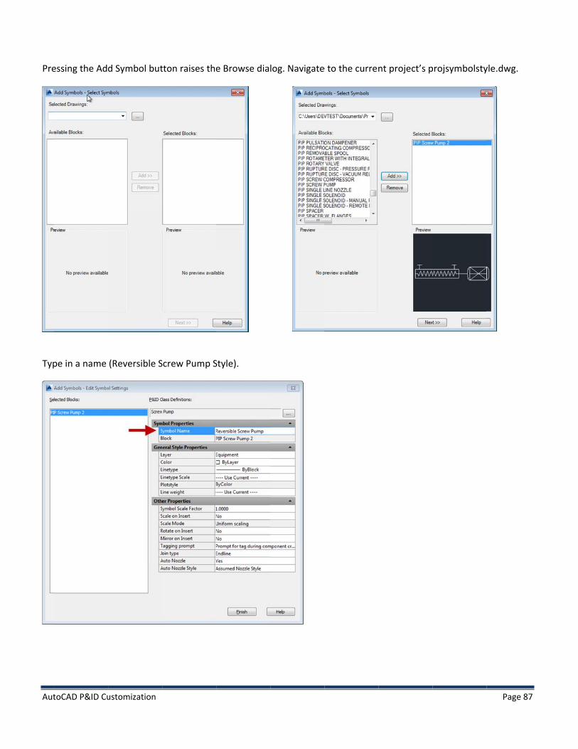
Aut
Pre
Typ
toCAD P&ID Cu
essing the Ad
pe in a name
ustomization
d Symbol but
(Reversible S
tton raises the
Screw Pump S
e Browse dia
Style).
log. Navigate
e to the currennt project’s pprojsymbolsty
Page 87
yle.dwg.

Aut
The
Forscr
Thebotloc
toCAD P&ID Cu
e new style is
r the final sterew pump usi
e following dittom of the p
cation on the
ustomization
s has now bee
p, press the “ng this new s
ialog indicatepalette group palette.
en created in
“Add To Tool style.
es that the toocurrently act
the Project S
Palette…” bu
ol has been stive, and you
Setup and is a
utton to place
uccessfully admay need to
available.
e a button on
dded, but be reposition in
the Tool Pale
aware that itn using drag/d
ette which wi
t will be addedrop into the
Page 88
ill create a
d to the desired

Aut
Theto clic
Froyou
toCAD P&ID Cu
Initial posi
e product wilmodify the imcking on the T
om here, you u can select t
ustomization
tion at the bottom
l do its best tmage. Using tTool and selec
may right cliche image of y
m of the current too
o provide a rhe tools of yocting “Proper
ck on the imayour choice fo
ol palette
easonable bitour choice, yorties…” will ra
age, and selecor the tool.
Pump
tmap on the tou can designaise the follow
ct “Specify Im
p after being move
tool palette fn a bitmap to wing dialog.
mage…” This w
ed
for the new torepresent yo
will raise a nav
ool, but you mour new tool.
vigation dialo
Page 89
may want Right
og in which

Aut
3. G
A b
toCAD P&ID Cu
Graphical St
brief descripti
• Symbol • Scale on
the TooScale w
• Scale Mscaling (
• Rotate othe Too
• Mirror othe tool
• Taggingprompt
• Join Typbeen givgraphica
o
o
o
o
ustomization
tyle Propert
ion of the rem
Scale: This isn Insert: This
ol Palette. If thill be used.
Mode: This is o(scaling differon Insert: Con
ol Palette. on Insert: Conl palette.
g Prompt: Coned to fill in ta
pe: Specifies hven to ‘Join Tal representa
Endline: Assto elbow. EraInline: AssetErasing the lSegment BreRetains the lSegment GroExample: pu
ties
maining Grap
the default scontrols whe
he user declin
only enabled wrently in X anntrols whethe
ntrols whethe
ntrols whetheag values whehow the asset
Type’ propertyation with res
et remains stasing the line cleans the linine erases theeaker: Insertsine group andoup Breaker:mps, blowers
hical Style pro
scale factor atether the usernes to manua
when “Scale od Y) is alloweer the user w
er the user wi
er the asset caen the asset ist is expected y of any P&IDpect to line.
ationary whee does not erane without bre asset. s into a line and line numbe Inserts into ls.
operties follo
t which the syr will be promlly scale the a
on Insert” is sed. ill be prompt
ill be prompte
an be tagged,s placed fromto join with t
D symbol to co
en line is movase the asset.reaking it. Mo
nd breaks theer for both linlines and brea
ows:
ymbol will bempted to scaleasset, the def
set to Yes, an
ted to rotate t
ed to mirror t
, and whethem the Tool Palthe line. In reontrol the be
ved. Moving t. oving the line
e line into twoe segments. aks line into t
e inserted. e the asset wfault scale fac
nd controls wh
the asset whe
the asset whe
er the user wiette. cent release
ehavior of sym
he asset or th
e causes the a
o segments inExample: Spetwo segments
hen it is dropctor specified
hether non-u
en it is dropp
en it is dropp
ll be automat
more emphambols especia
he line causes
asset to move
n the same grec Break, etc. s and two line
Page 90
pped from d in Symbol
uniform
ped from
ped from
tically
ses has ally the
s the line
e as well.
roup.
e groups.

Aut
4. Havandthesel
5. AThepowDef
Rai
toCAD P&ID Cu
o • Auto No
creation• Auto No
not gendata cac
Manually swving created d raise the pre newly creatected Screw
Associating e ability to hawerful when finition can h
ise the Projec
ustomization
No Join: Doeozzle: Indicaten adds a row ozzle Style: Sperate graphicche for the no
witching betthe additiona
roperties paleed style, “RevPump will dra
Graphical Save multiple Sthese various
have a single P
ct Setup dialo
es not conneces whether a to the datacapecifies the stcs (useful if thozzle.
tween Graphal symbol for ette. The propversible Screwawing using t
tyles with aStyles availabs graphical reProperty defi
og, navigate to
ct with lines. nozzle should
ache. tyle of nozzlehe nozzle is al
hical Styles Screw Pump,
perties palettw Pump Stylehe selected S
Property le for a given
epresentationned that is of
o the Screw P
d automatica
that should blready part of
, place a screwe will show b
e”. You can usStyle.
P&ID object ns are combinf the “Symbol
Pump, and ad
ally be created
be generatedf the asset gr
w pump in thboth the originse the Tool Pa
type is generned with a spel List” type.
dd a new Prop
d when a line
d. The “Assumaphics), but d
he drawing. Senal style “Screalette to selec
rally useful, becific propert
perty.
e joins this ass
med Nozzle Stdoes add a ro
elect the screew Pump Styct either Style
but becomes mty. Each P&ID
Page 91
set. Nozzle
tyle” does ow in the
ew pump yle” and e, and the
more Object

Aut
Thinam
TheListSty
AftFor“Bl
toCAD P&ID Cu
is raises the “me and its de
e “Symbol List”, except tha
yle. Using the
ter adding ther each row, aock Value” co
ustomization
“Add Propertyescription. Th
st Property” dat each prope“Add Row…”
e rows for “Yell the Graphicolumn. Select
y” dialog. Seleen press OK.
dialog allows yerty VALUE al” button, and
es” and “No”,cal Styles thatt the new “Re
ect “Symbol L
you to definelowed definedefine two v
, the Symbol t have been deversible Scre
List” as the ty
e the items in d for the pro
values, “Yes” a
List Property defined for a Sew Pump Style
ype, and ente
the list. This perty is assocand “No” for
dialog showsScrew Pump ae” to be asso
r “Reversible
property is sciated with a the “Reversib
s the rows thare shown as
ociated with t
” for the prop
imilar to a “Sspecific Grapble” property
at have beens options undhe “Yes” valu
Page 92
perty
election phical y.
defined. er the
ue of the

Aut
newnew
Ok
Plathesho
toCAD P&ID Cu
w Reversible w Reversible
out of this di
ace a Screw Pe right. The neown. (You ma
ustomization
property, andproperty.
ialog. Back in
ump in the drew “Reversib
ay have to clic
d select the o
the Project S
rawing. Initiale” property
ck in the draw
original “Screw
Settings, the n
lly it will haveis shown. Sel
wing pane to t
w Pump Style
new property
e the original ecting the “Ytrigger the re
e” to be assoc
y is shown. Se
representaties” option w
edraw of the S
ciated with th
elect No as th
on. Open theill cause the aScrew Pump.)
he “No” value
e default valu
e data grid analternative st)
Page 93
e of the
ue.
d scroll to yle to be

Aut
Thetecinceac
6. An
Usigra
In aTagfacare
toCAD P&ID Cu
ere need not chnique is useclude 3 open ach of the 3 op
Using Multiother use of
ing the technaphical style i
a project contg value, TK-10ct that the Tage really mean
ustomization
be a one to oed to implemeand 3 closed pen and close
ple Graphicamultiple Grap
iques above, s a tall, vertic
taining three 00. When theg value is alret to represen
one corresponent the “Normvariants, but
ed values.
al Style for aphical Styles i
three additiocal vessel. The
drawings, plae second attemeady in use, at portions of
ndence betwmally” properonly two Gra
an Asset thas to support a
onal graphicae three new s
ace a vessel impt is made tlthough in a dthe same ass
een the proprty of Hand V
aphical Styles
at Spans Draa single asset
l styles are destyles are sho
n each drawito assign thisdifferent drawset, with the f
perty values aValves in the p
(one open an
awings t that spans m
efined here foown below.
ng. When pros tag value, wwing, and quefollowing dial
nd the Graphproduct. The nd one filled)
multiple draw
or the Vessel
ompted, assighich is a dupleries you as tlog.
hical Styles. T“Normally” v are used to r
wings.
class. The de
gn each vesselicate, it recogto whether th
Page 94
his exact values represent
efault
el the same gnizes the
hese assets

Aut
Sel
In tdrathedra
7. AAtt
TheAtt
AdfeaAttthepoi
toCAD P&ID Cu
ect “Assign th
the image abawing shows te data grid shawings, with a
A note aboutachment Poi
e first purpostachment Poi
ditionally, forature, when ctachmentPoine flow directioint to determ
ustomization
his tag to the
ove, a differethe bottom, mown, there isan independe
ut Attachments in the blo
se is to providnt in the equ
r assets that hcompleted, wnt2, and will uon of the line
mine if a line is
selected com
ent Graphical middle, and ts only one inteent and appro
ent Points ock definition
de snap pointsipment’s bloc
have flow direill interpret thuse this to rec upon which
s fully connec
mponent” for
Style has beeop of the Vesernal represeopriate repres
of a graphica
s. When you ck definition f
ection, the nahe flow directcognize situatit sits. Validat
cted to an ass
each vessel.
en assigned tossel respectiventation (PnPsentation in e
al style have t
begin drawinfunctions as a
aming of the tion of an asstions in whichtion will also
set.
o the vessel ively. HoweverID) for the veeach drawing
two purposes
ng a PipeLine a snap point.
Attachment Pset as going frh an inline ascheck for line
n each drawir, note that inessel. Thus, thg.
s.
from a piece
Points is imporom Attachmset’s flow dire connections
ng, so that ean the Project he single vess
of equipmen
ortant. The vamentPoint1 to
ection is in cos at the attac
Page 95
ach View of
sel spans 3
nt, any
alidation
onflict with chment

Aut
FinenddetdracouAtt
The
B.Dy
A Dthewean
toCAD P&ID Cu
nally, some asd connection termine wheraw. The intenunterclockwistachmentPoin
e following ex
Dynamicnamic Assets
Dynamic Assee asset itself. ell. One of the
Annotation is
ustomization
ssets, such as graphics to b
re to draw. Intion to suppose degrees, tont1:EndCode1
xample show
c Assets combine the
et is an asset wAs the values
e main motivas that the tex
Hand Valves,be drawn on tn addition, theort endcodes o the attachm180.
s attachment
e principles di
which intrinsis of the asset’ations for defxt is fully integ
, support the the valve. Theey rely on theis indicated b
ment point. Th
t points with
scussed in bo
ically includes’s properties
fining a Dynamgrated with th
“End Connecese graphics ae label of the by adding a cohus, an attach
endcodes def
oth Annotatio
s textual elemchange, the t
mic Asset, as he asset grap
ctions” propealso rely on thattachment p
olon, the worhment point l
fined for both
on Styles and
ments based otextual represopposed to u
phics, and can
erty. This prophe attachmenpoint to deterd EndCode, alabel could be
h a 2 port and
Graphical Sty
on the asset’ssentation of t
using a regulannot be move
perty allows fnt points in ormine at whaand an angle,e:
d a 4 port val
yles.
s properties athose values
ar asset combed away from
Page 96
for various rder to
at angle to , in
ve.
as part of update as
bined with the asset.

AutoCAD P&ID Customization Page 97
As with an Annotation, the properties to retrieve are specified using a Format String, associated with an Attribute Definition, as part of the Block Definition for the symbol. All Format String syntax is supported. The target object used to evaluate the Format String is the Dynamic Asset itself.
Including a Format String in the Block Definition of a Graphical Style is sufficient to alert the program to create a Dynamic Asset when the asset is placed in the drawing. There are no other settings that need to be touched, no other support required.
Also, it is perfectly safe to modify the Block Definition of a Graphical Style to add or remove Format Strings. After the changes are made, the program will automatically convert all the existing assets in the drawing between being a Dynamic or a regular Asset, depending upon the current Block Definition.
1. Special Behaviors of Off Page Connectors In AutoCAD P&ID, the Off Page Connectors are special types of Dynamic Assets.
First, the special “use mate” syntax is included in the Format String of the Block Definition, in order to show values from the “other” drawing in which the mated connector resides. This syntax is not supported by the “Assign Annotation Format” dialog, and must be inserted manually while editing the block definition.
For example:
#(Drawing.General.PnID)
#(=Drawing.General.PnID) The first Format string would return the PnID (drawing number) of the drawing in which the target object resides.
The second Format String would return the PnID (drawing number) of the drawing in which the target object’s mate resides.
The equal sign just inside the opening parenthesis specifies “use mate’s property.” Naturally, if the target object is not a mate-able type, then this format string will not evaluate, and the DOT will be seen instead.

Aut
In tthearr
Secexasymsershothobehandthesucundthepro
toCAD P&ID Cu
the image bee arrow, and trow, because
condly, the imactly the commbol ships wirvice code, anown on the leough, that thehavior is specd also because product, extccessfully accderstanding oe specific propoperties to fa
ustomization
low, the connthe connectothese connec
mplementatiobination of gth Format str
nd the mate’seft, and the de values read cific to our shse the dynamtensive modifomplished byof Dynamic Bperties displail.
nector on theor on the rightctors have be
on of the shipraphics and Frings defined,s drawing numrain on the riin the same tipping symboic blocks for tfication of they most users, lock authorin
ayed in our sh
e left, in drawt, in drawing
een mated.
ping connectFormat String, from top to
mber. In the imght is invertetop to bottom
ols, and is unfthe Off Page Cese blocks is dbut major sh
ng, and after mhipping OPC b
ing 1, automa2, automatica
tor types inclus in our shippbottom, to shmage below,
ed due to its lom order on thfortunately noConnector ardiscouraged.
hape changes making a backblocks may ca
atically showally shows th
udes some spping OPC symhow the connthe default o
ocation on a he second draot user extenrrows are amo
Minor modifshould be un
kup. Repositiause the auto
s the value 2 e value 1 insi
pecial coding tmbols. For exa
nector numbeor “right side downward flo
ain, in spite ofnsible at this tong the mostfication such ndertaken ononing, changmatic re-orie
inside the rigde the right s
that is relevaample, the Cloer, the destinup” orientatiowing line. Nf it being invetime. For this t complex shias font changly with a gooing, or erasinntation of tho
Page 98
ght side of side of the
nt to osed Drain nation line
on is otice,
erted. This reason, pped in ges can be d g any of ose

Aut
If tBlo
2. SGemo
Whlinelineatt
Whannthe
Fororior
Thiori
VFor
For
toCAD P&ID Cu
he exact comock Definition
Special Behaneral Instrum
odifiable in th
hile placing a e segment or e is part of thached to ano
hen an Inline notation, whie annotative b
r both Generaentation of thinline with, a
is differs fromentation of th
II. Propr some P&ID
r example:
ustomization
mbination of pn, a combinati
aviors of Insments, and the
is release.
general instranother assee General Ins
other asset via
Instrument, sich is the instbubble. In thi
al Instrumenthe contained vertical pipe
m the default he text.
perty Prclasses, their
properties, poion of the ass
struments e bubbles for
ument, an adet via a Leadestrument itsea a leader, th
such as a magrument bubbs case, the le
ts and the anntext, regardleline will still h
behavior for
opagatproperties ar
ositions, and bset and annot
r Inline Instru
dditional promer. In the caself, and is drawe leader line
gnetometer isble. After placader is actua
notative bubbess of the anchave text that
annotations,
ion/Acqre closely ass
behaviors is ttations can of
ments, exhib
mpt is availabe of General Inwn by the Gewill be insert
s placed, the cement, the plly a separate
ble of Inline Ichorage of tht reads horizo
in which a ve
quisitioociated with
too difficult toften be used t
it special beh
ble by which tnstruments aneral Instrumed as a piece
product promproduct placee AutoCAD Le
nstruments, the bubble. In ontally.
ertical target
on the propertie
o accomplish to accomplish
haviors which
the instrumenattached to a ment. When ae of Tubing.
mpts for a pos a leader bet
eader entity.
the product eother words,
results in ver
es of another
in the conneh the desired
are not user
nt can be attaPipe Line, the
a General Inst
sition for thetween the bu
enforces a ho a bubble anc
rtical (bottom
r P&ID class.
Page 99
ctor’s own results.
ached to a e leader trument is
default ubble and
orizontal chored to,
m to top)
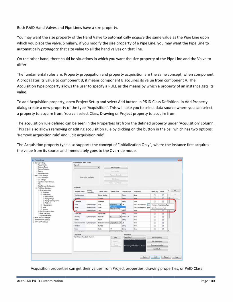
Aut
Bot
Youwhaut
Ondiff
TheA pAcqval
To diaa p
TheThi‘Re
Thethe
toCAD P&ID Cu
th P&ID Hand
u may want thich you placetomatically pr
the other hafer.
e fundamentapropagates itsquisition typeue.
add Acquisitialog create a nproperty to ac
e acquisition is cell also alloemove acquis
e Acquisition e value from i
Acquisit
ustomization
d Valves and P
he size propee the valve. Siropagate tha
and, there cou
al rules are: Ps value to come property all
ion property,new propertycquire from. Y
rule defined ows removingition rule’ an
property typits source and
tion propertie
Pipe Lines hav
erty of the Haimilarly, if yout size value to
uld be situatio
Property propmponent B; itows the user
open Projecty of the type ‘You can selec
can be seen ig or editing ad ‘Edit acquis
e also suppord immediately
es can get the
ve a size prop
and Valve to au modify the o all the hand
ons in which
pagation and t means comp
to specify a R
t Setup and s‘Acquisition’. t Class, Draw
n the Propertcquisition rul
sition rule’.
rts the concey goes to the
eir values from
perty.
automaticallysize property
d valves on th
you want the
property acqponent B acquRULE as the m
elect Add butThis will takeing or Project
ties list from le by clicking
pt of “InitializOverride mo
m Project pro
y acquire the sy of a Pipe Linhat line.
e size propert
uisition are tuires its value
means by whi
tton in P&ID Ce you to select property to
the defined pon the butto
zation Only”, ode.
operties, draw
same value ane, you may w
ty of the Pipe
he same conce from compoich a property
Class Definitict data source
acquire from
property undn in the cell w
where the in
wing properti
s the Pipe Linwant the Pipe
Line and the
cept, when coonent A. The y of an instan
on. In Add Pre where you c
m.
er ‘Acquisitiowhich has two
nstance first a
es, or PnID C
Page 100
ne upon e Line to
Valve to
omponent
nce gets its
roperty can select
on’ column. o options;
acquires
lass

Aut
toCAD P&ID Cu
Propert
ustomization
ties.
Page 101

Aut
V
A.TherulForpro
Whparstr
The
toCAD P&ID Cu
• When athat is a
• When apicked uchanges
• Acquisit• Acquisit
Enginee
III. App
. Format e following foes, auto-genermat/Assign Aogrammatical
hile there is articular, the aings. (This tok
e auto-genera
ustomization
n instance pracquiring. In tn instance pr
up by the insts made here dtion rule can tion propertyeringItems lev
pendix
string synormat string seration, and aAnnotation Folly create form
n overarchingassign-back token is hidden
ation token m
roperty is at tthis mode theroperty is at ttance doing tdo not get pube edited or
y is just anothvel, all Class D
ntax syntax allows assign-back stormat dialogsmat strings fo
g syntax, portoken should b in the variou
may be used w
the “Acquire”e data is in Rethe Local modhe acquiring.
ushed back toremove via Per type of pro
Definitions be
identificationtates. (This is s.) Knowledgeor their own f
tions of the sybe used only wus Tag Format
with either, b
mode, changead-only formde called as “O
This mode leo source proproject Setup. operties, if yo
elow that leve
n/tokenizatiothe underlyin
e of these detfeatures.
yntax are mowith Tag Formt UIs.)
ut has few if
ges to the soumat and canno
Override” moet you enter nerty.
ou setup a (Acel will inherit
on of retrievabng syntax thatails may be u
ore appropriamat strings, n
any use case
urce are pickeot be enteredode, changes new values m
cquisition) prthe property
ble propertieat is created buseful for dev
te to Tag Forever with An
s for Annotat
ed up by the d manually.
to the sourcemanually, but r
roperty at the.
s, formattingby the Assign velopers who
mat strings. Inotation Form
tions.
Page 102
instance
e are NOT remember
e
g/input Tag
o wish to
n mat

AutoCAD P&ID Customization Page 103
The formatting token is used by several dialogs as a means to enforce input for Tag Formats, but is used to apply formatting to the output of Annotation Formats.
A field is delimited by the form #().
A class property is indicated by Class.Property. A drawing property is indicated by Drawing.Category.Property. A project property is indicated by Project.Category.Property.
Examples of simple retrievable properties are:
#(CentrifugalPump.FlowRate) #(Project.General.Name) #(Drawing.General.Area) The user may combine an expression with a property, for the purposes of formatting, autogeneration, and assignment.
If the user wants to specify a format for a property, it must be included inside the field, specified with %.
For example, if the Flow Rate should always be shown as 3 numbers, then the field would be:
#(CengrifugalPump.FlowRate%NNN) If the value needs to be autogenerated, the @ sign is used instead. #(PipeLine.LineNumber@NNN)
(The @NNN syntax immediately above was in support of an early concept for arbitrary autogeneration which was based on a dumb counter. It is not surfaced in the UI, but will produce a value if created and assigned via APIs.)
To specify the lookup location for auto-generation source and increment value (as opposed to arbitrary generation), a $ is added at the end of the @ portion of the field. #(PipeLine.LineNumber@NNN$Project.LastLineNumber) If the autogenerated value should be assigned back, the ^ sign is added. #(PipeLine.LineNumber^@NNN$Project.LastLineNumber) If the user must input a value to be assigned back, the autogenerate symbol is not used. #(PipeLine.LineNumber^NNN)
For variants where user input is expected, lack of input will be indicated by the mask symbol ‘?’.
Note that “simple” auto-generation as described in section III.D.1 is implemented directly in the code, and is not represented by the Format String syntax in any way.
If the user wants to specify an optional field, the ~ symbol is used. For example, an optional field would be indicated by: #(HotWaterPipe.Insulation~A*)
Optional fields are never auto-generated, but may be assigned back. Optional fields will not cause an error condition if they cannot be assigned or retrieved. They will simply be skipped. Note that the optional syntax isn’t surfaced in any UI.
Expressions can also be specified independent of retrievable properties. For example, to simply generate a 3-digit-minimum numeric value, the syntax would be:
#(@NNN) Again, the syntax above was in support of the early counter-based arbitrary generation, which is not surfaced in the UI.

AutoCAD P&ID Customization Page 104
To require user input of a 3-digit-minimum number, the syntax would be:
#(%NNN) When being evaluated, any text that occurs between fields is passed through unchanged. This is referred to as “free text.” Delimiters fall into this category.
If the user specified AREA-LINENUMBER, the format string would be:
#(Drawing.Category.Area)-#(Primary.LineNumber) Note the “dash” delimiter between the fields.
As is standard in various programming languages, the backslash character can be used to ‘escape’ special characters outside of the fields. If the user wants to use the # character as a delimiter, it should be escaped to prevent it from being interpreted as the beginning of a field.
Note that the output of evaluating the format is a single text item, not multi-line text, so the newline character is not valid.
To specify that the property should be retrieved from the target object’s mate (in the special case of CONNECTORS), the property should be pre-pended by the equal sign.
For example, to retrieve the PnID number of the Off Page Connector in the other drawing from the target Off Page Connector, the format string would be:
#(=Drawing.General.PNID) Setting and retrieving the Format Strings of Tag Formats and Annotation Formats programmatically is done via the AcPpTagFormat and AcPpAnnotation class APIs respectively.
B. APIs The following header files will be of interest to developers wishing to work directly with Annotations and Tag Formats.
The header file: AcPpAnnotation.h contains methods for creating P&ID Annotations, getting and setting annotation properties (including accessing the Format Strings of specific attributes within the block reference), finding the associated annotation style, etc.
The header file: AcPpAnnotationUtils.h contains methods for identifying whether a given text or block reference entity is a P&ID Annotation, and for refreshing P&ID Annotations.
The header file: AcPpTagFormat.h contains methods for working with Tag Formats, getting and setting of Tag Format properties (including getting and setting the Format String) and storing a Tag Format in the AcDbDatabase.
The header file AcPpTagUtils.h contains methods for validating that a Format String is properly formed, and for evaluating a Format String against a target AcDbObjectId.

AutoCAD P&ID Customization Page 105
NOTE THAT the AcPpTagUtils namespace was unfortunately misnamed in the API. This should have been AcPpFormatUtils. Do not let the API namespace confuse you into thinking that Format Strings are equivalent to or only for use by the Tag feature.
DISCLAIMER:
Autodesk may make statements regarding planned or future development efforts for our existing or new products and services. These statements are not intended to be a promise or guarantee of future delivery of products, services or features but merely reflect our current plans, which may change. Purchasing decisions should not be made based upon reliance on these statements.
Autodesk assumes no obligation to update these forward-looking statements to reflect events that occur or circumstances that exist or change after the date on which they were made.
Recommended


![RD) ORDER CONTROL Abstract EXTENSION FOR …...ip 397 NIGHTINGALE PUBLICATIONS AND RESEARCH INTERNATIONAL ] ISSBN: 1839-2373 IJMSE Vol. 9, NO. 7] utoCAD 2007 software at a scale of](https://img.pdfslide.us/doc/110x75/5f09b2d07e708231d428166f/rd-order-control-abstract-extension-for-ip-397-nightingale-publications-and.jpg)