Embed Size (px)
Citation preview

Autod
Adva
Admi
desk A
nced
inistra
AutoC
Config
ator T
CAD P&
gurat
Trainin
&ID 2
ion G
ng
2014
uide
Contents Chapter 1: Project Configuration .......................................................................................................................... 6
Project Files ...................................................................................................................................................... 6
Read-Write Issues ............................................................................................................................................. 7
Other Files Important to the Project ................................................................................................................ 7
Summary of Access Rights ................................................................................................................................ 8
Chapter 2: Project Setup ...................................................................................................................................... 9
Create a Project ................................................................................................................................................ 9
Chapter 3: Data Manager ................................................................................................................................... 11
Export/Import ................................................................................................................................................. 11
Set Up and Export Reports ......................................................................................................................... 11
Procedures: Export Reports ........................................................................................................................ 12
Import Reports and Reconcile Changes ..................................................................................................... 12
Procedures: Import Reports ....................................................................................................................... 14
Chapter 4: Project Tool Palettes ......................................................................................................................... 16
Copy the default tool palettes to the network ............................................................................................... 16
Chapter 5: Project Customization ....................................................................................................................... 19
Symbols ........................................................................................................................................................... 19
Create a pump from an existing pump ....................................................................................................... 19
Properties ....................................................................................................................................................... 21
Set up Properties for Components and Lines ............................................................................................. 21
Tag Formats .................................................................................................................................................... 22
Setting up tag formatting ........................................................................................................................... 22
Set Up Tag Formatting for a Class .............................................................................................................. 22
Set Up Tag Formatting Using Acquiring Properties .................................................................................... 23
Set Up Tag Formatting for a Pipe Line Group ............................................................................................. 23
Understand Default Tag Formatting Templates ......................................................................................... 23
Build Tag Formatting Expressions ............................................................................................................... 23
Understand Tag Uniqueness ...................................................................................................................... 24
Annotation ...................................................................................................................................................... 30
Setting up Annotations ............................................................................................................................... 30
Tool Palettes ................................................................................................................................................... 38
Rearranging Tools and Tool Palettes .......................................................................................................... 40
Sharing project drawings ................................................................................................................................ 40
Chapter 6: Printing Project drawings .................................................................................................................. 41
Plotting ........................................................................................................................................................... 41
Plotter Manager ......................................................................................................................................... 41
Layouts ........................................................................................................................................................ 41
Page Setups ................................................................................................................................................ 41
Plot Styles ................................................................................................................................................... 41
Plot Stamps ................................................................................................................................................. 42
Publishing to DWF .......................................................................................................................................... 42
To publish a DWF file, use any one of the following methods: .................................................................. 43
Viewing P&ID DWF files in AutoCAD P&ID ..................................................................................................... 44
The Publish Dialog Box ............................................................................................................................... 45
Online Collaboration ................................................................................................................................... 48
Chapter 7: Audit and Maintain Projects ............................................................................................................. 48
Project Audits ................................................................................................................................................. 48
Project Compression ....................................................................................................................................... 49
Procedures: Audit and Maintain Projects ....................................................................................................... 49
Chapter 8: Customization ................................................................................................................................... 50
Symbols ........................................................................................................................................................... 50
Convert AutoCAD Block to P&ID Symbol .................................................................................................... 50
Adding a New Block to Your Project ............................................................................................................... 51
Data Properties ............................................................................................................................................... 54
Set Up Properties ........................................................................................................................................ 54
Procedures: Set Up Properties ................................................................................................................... 55
Exercise: Adding new properties ................................................................................................................ 57
Layers & Colors ............................................................................................................................................... 58
Component Characteristics ............................................................................................................................ 61
Set Up Class Definitions for Components and Lines ................................................................................... 61
Procedures: Set Up Class Definitions for Components and Lines .............................................................. 62
Set Up Symbol and Line Settings ................................................................................................................ 65
Procedures: Set Up Symbol and Line Settings ............................................................................................ 65
Configure Symbols for Components ........................................................................................................... 67
Procedures: Configure Symbols for Components ...................................................................................... 70
Configure the Appearance of Lines ............................................................................................................ 77
Procedures: Configure the Appearance of Lines ........................................................................................ 77
Procedures: Set Up Properties ................................................................................................................... 79
Set Up Property Acquisition ....................................................................................................................... 81
Procedures: Set Up Property Acquisition ................................................................................................... 84
Set Up Selection and Symbol Lists .............................................................................................................. 92
Procedures: Set Up Selection and Symbol Lists .......................................................................................... 93
OffPage Connectors ...................................................................................................................................... 103
Procedures: Set Up OffPage Connectors .................................................................................................. 103
SQL Server ..................................................................................................................................................... 105
Vault .............................................................................................................................................................. 106 Appendix A Additional Exercises ................................................................................................................... 108
Creating a P&ID drawing .............................................................................................................................. 108
Launching AutoCAD P&ID ............................................................................................................................. 108
Creating a project ......................................................................................................................................... 110
Create a drawing and place equipment ....................................................................................................... 115
Create drawing ......................................................................................................................................... 115
Place Equipment ....................................................................................................................................... 116
Adding primary and secondary lines ............................................................................................................ 118
Primary lines ............................................................................................................................................. 118
Secondary lines ......................................................................................................................................... 118
Placing inline components ............................................................................................................................ 119
Adding Instrumentation and tags ................................................................................................................. 121
Add instruments ....................................................................................................................................... 121
Add tags .................................................................................................................................................... 122
Offpage Connectors ...................................................................................................................................... 123
Place Connectors on first drawing ............................................................................................................ 123
Create second drawing ............................................................................................................................. 124
Place items on new drawing ..................................................................................................................... 125
Tagging Pipelines .......................................................................................................................................... 126
Connecting Off Page Connectors .................................................................................................................. 129
Adding Drawing and Project Properties ....................................................................................................... 131
Drawing properties ................................................................................................................................... 131
Project properties ..................................................................................................................................... 132
Project Transmittal ....................................................................................................................................... 134
Data Manager ............................................................................................................................................... 137
Export to Excel .............................................................................................................................................. 140
Reporting ...................................................................................................................................................... 142
Appendix B Glossary of P&ID Terms ................................................................................................................. 144
Glossary ........................................................................................................................................................ 144
Appendix C ........................................................................................................................................................ 148
Glossary of Application Terms ...................................................................................................................... 148
AutoCAD P&ID Advanced Configuration Guide Page 6
Chapter 1: Project Configuration
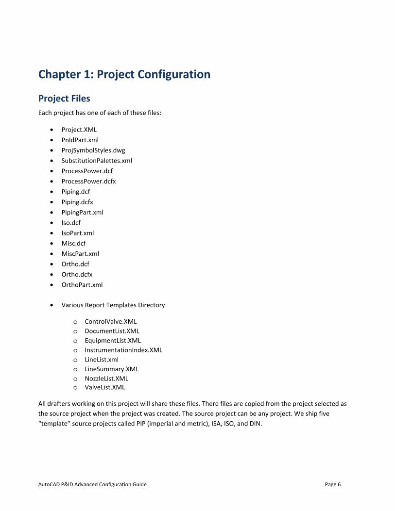
Project Files Each project has one of each of these files:
• Project.XML • PnIdPart.xml • ProjSymbolStyles.dwg • SubstitutionPalettes.xml • ProcessPower.dcf • ProcessPower.dcfx • Piping.dcf • Piping.dcfx • PipingPart.xml • Iso.dcf • IsoPart.xml • Misc.dcf • MiscPart.xml • Ortho.dcf • Ortho.dcfx • OrthoPart.xml
• Various Report Templates Directory
o ControlValve.XML o DocumentList.XML o EquipmentList.XML o InstrumentationIndex.XML o LineList.xml o LineSummary.XML o NozzleList.XML o ValveList.XML
All drafters working on this project will share these files. There files are copied from the project selected as the source project when the project was created. The source project can be any project. We ship five “template” source projects called PIP (imperial and metric), ISA, ISO, and DIN.

AutoCAD P&ID Advanced Configuration Guide Page 7
Once you start working, the data cache is created – one per project. These cache files are: • ProcessPower.dcf • ProcessPower.dcfx • Iso.dcf • Iso.dcfx • Misc.dcf • Misc.dcfx • Ortho.dcf • Ortho.dcfx • Piping.dcf • Piping.dcfx
If a project is using SQL Server, the *.dcf files are not databases, but xml connection files which point the program to the correct SQL Server database.
The first time a substitution palette is invoked, you also get a project file called SubstitutionPalettes.xml
Read-Write Issues PnIdPart.XML needs to be writable by all drafters creating content in this project. (i.e., anyone using the program to draw P&IDs). This xml happens to use “Project Autogen” values for automatic tag generation, the last autogen value is also stored here.
Of course the data cache ProcessPower.DCF & ProcessPower.dcfx files need to be writable if you are creating content.
The other project files can be read only by drafters creating content in this project.
Other Files Important to the Project The DWT (drawing template) file can be either shared from some project directory OR on each user’s workstation. The project.xml points to the DWT, and this path can be either local or network. Out of the box it is where all the other ACAD DWT files - C:\Users\%USERNAME%\AppData\Local\Autodesk\AutoCAD Plant 3D 2015\R20.0\enu\Template
Undoubtedly many projects will want the TOOL PALETTE to be from a shared project file instead of from the local copies in each user’s C:\Users\%USERNAME%\AppData\Roaming\Autodesk\AutoCAD Plant 3D 2015\R20.0\enu\Support\ToolPalette
PnIdPart.XML contains • Project NAME, DESCRIPTION • Paths to the REPORT xml files • Auto-gen definitions • Path to this project and project files (ProjSymbolStyles.dwg)
AutoCAD P&ID
• Path
ProcessPowe• ALL t• PRO
num• Disp• Defa• If the
ProjSymbolS• The • Any • Tag f
The various JOINS, FILTE
The ProcessP
Summar
Advanced Confi
h to DWT file
er.dcfx is the the CLASSES (PERTIES for t
mber, text, elelay Names fo
ault values fore property is
Styles.DWG cosymbols (blocannotations format defini
report tempRS, SORTS, an
Power.dcf file
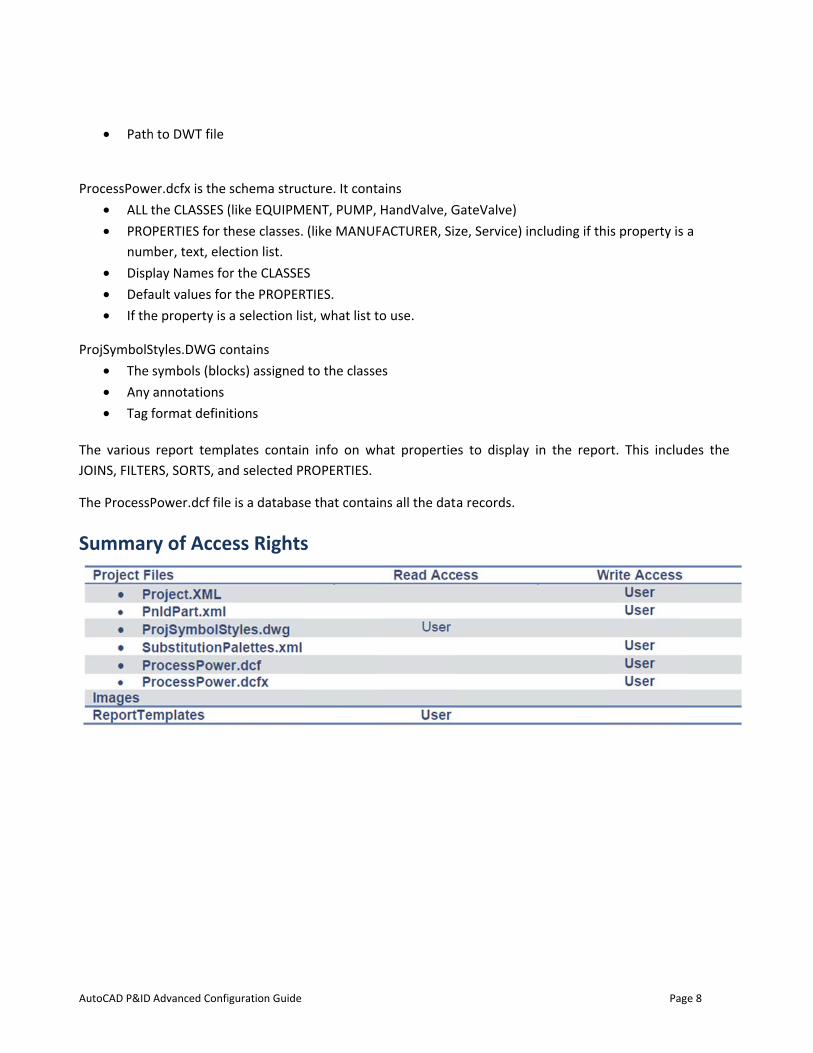
ry of Acce
iguration Guide
schema struc(like EQUIPMhese classes.
ection list. or the CLASSEr the PROPERa selection lis
ontains cks) assigned
tions
plates containnd selected P
e is a databas
ess Rights
cture. It contaENT, PUMP, (like MANUF
S RTIES. st, what list to
to the classe
n info on whROPERTIES.
e that contai
s
ains HandValve, G
FACTURER, Siz
o use.
es
hat propertie
ns all the dat
GateValve) ze, Service) in
es to display
a records.
ncluding if thi
in the repor
Pag
is property is
rt. This includ
ge 8
a
des the
AutoCAD P&ID
Chapte
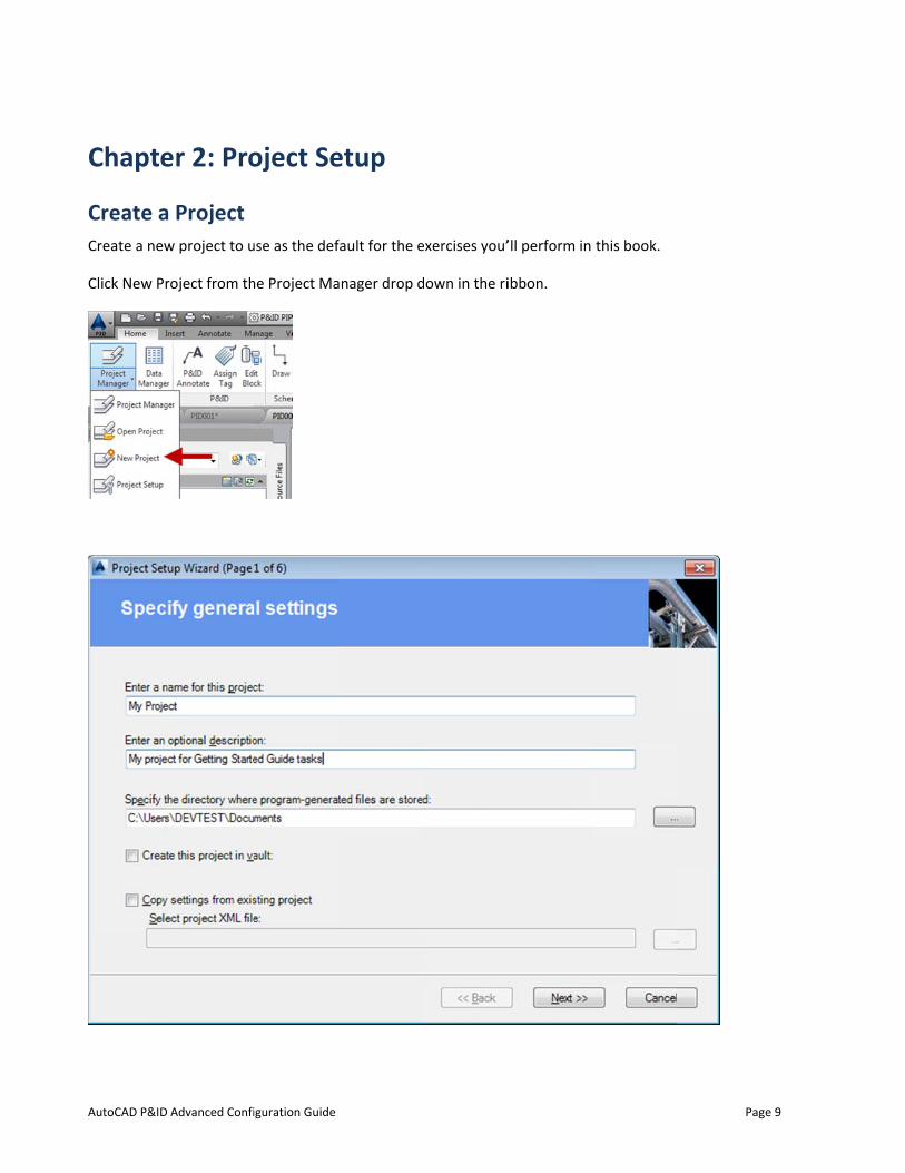
Create aCreate a new
Click New Pr
Advanced Confi
er 2: Pro
Project w project to u
roject from th
iguration Guide
oject Se
use as the def
he Project Ma
etup
fault for the e
anager drop d
exercises you’
down in the ri
’ll perform in
ibbon.
this book.
Pag
ge 9
AutoCAD P&ID
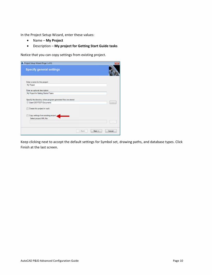
In the Projec• Nam• Desc
Notice that y
Keep clickingFinish at the
Advanced Confi
ct Setup Wizame – My Projecription – My
you can copy
g next to accelast screen.
iguration Guide
rd, enter theect project for G
settings from
ept the defau
se values:
Getting Start
m existing pro
lt settings for
Guide tasks
ject.
r Symbol set,
drawing pathhs, and datab
Page
base types. Cl
e 10
ick
AutoCAD P&ID Advanced Configuration Guide Page 11
Chapter 3: Data Manager
Export/Import
Set Up and Export Reports
You set up reports in the Project Manager. You can export reports either from the Project Manager or the Data Manager, but you view and manipulate reports in the Data Manager.
You can export a report on a project. You have the choice of a number of preset report templates. You can select multiple report types for a single report, in which case, each report type will be on a separate worksheet of the Microsoft Excel spreadsheet. You can export a new report from a template, or copy and rename an existing report.
Reports can also be created externally to AutoCAD P&ID via the report creator application. This application allows you to define a format, and then populate that format with data from your project.
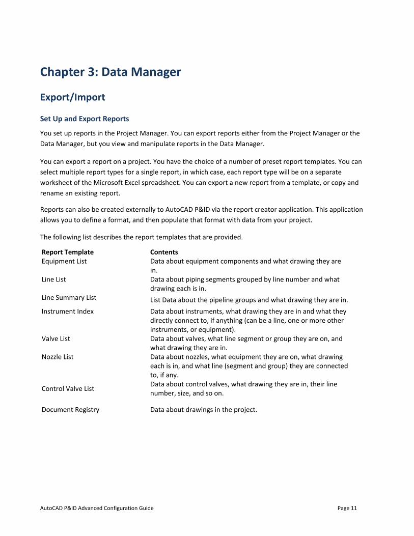
The following list describes the report templates that are provided.
Report Template Contents Equipment List Data about equipment components and what drawing they are
in. Line List Data about piping segments grouped by line number and what
drawing each is in. Line Summary List List Data about the pipeline groups and what drawing they are in. Instrument Index Data about instruments, what drawing they are in and what they
directly connect to, if anything (can be a line, one or more other instruments, or equipment).
Valve List Data about valves, what line segment or group they are on, and what drawing they are in.
Nozzle List Data about nozzles, what equipment they are on, what drawing each is in, and what line (segment and group) they are connected to, if any.
Control Valve List Data about control valves, what drawing they are in, their line number, size, and so on.
Document Registry Data about drawings in the project.
AutoCAD P&ID
Procedures
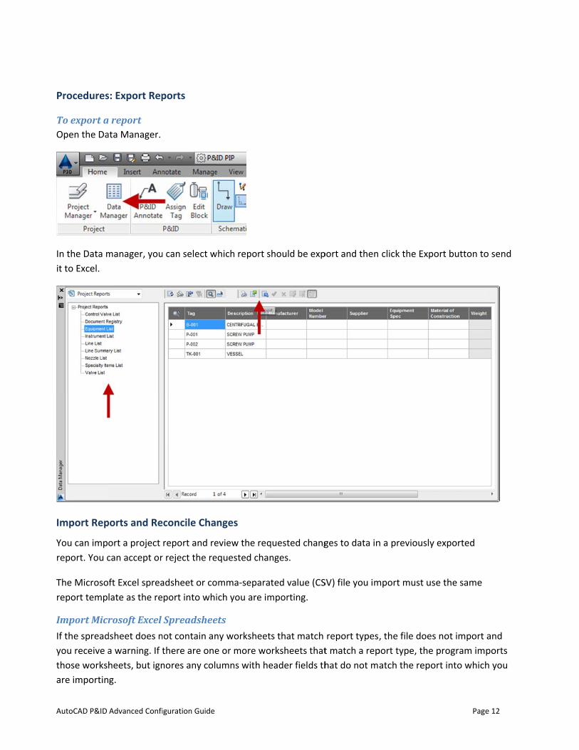
To export aOpen the Da
In the Data mit to Excel.
Import Rep
You can impreport. You c
The Microsoreport temp
Import MicrIf the spreadyou receive athose worksare importin
Advanced Confi
s: Export Rep
a report ata Manager.
manager, you
ports and Re
ort a project can accept or
ft Excel sprealate as the re
rosoft Excel dsheet does na warning. If theets, but igng.
iguration Guide
ports
u can select w
econcile Cha
report and rer reject the re
adsheet or coport into whi
Spreadsheenot contain anthere are onenores any col
which report s
nges
eview the reqequested chan
omma-separatich you are im
ets ny worksheete or more woumns with he
hould be exp
quested changnges.
ted value (CSmporting.
s that match rksheets that
eader fields th
port and then
ges to data in
SV) file you im
report types,t match a rephat do not m
click the Exp
n a previously
mport must us
, the file doesport type, theatch the repo
Page
ort button to
y exported
se the same
s not import a program imp
ort into which
e 12
o send
and ports h you
AutoCAD P&ID Advanced Configuration Guide Page 13
Import CSV Files If the report type of the imported CSV file does not match the report type into which you are importing, the import ignores the content. For example, you select a report type for a Valve List. If you import a CSV file containing an Equipment List, the import ignores the Equipment List report because it does not contain valve data.
Whether dealing with a spreadsheet or a CSV file, you can only import primary table files back into AutoCAD P&ID. For example, a valve list can only import into the valve table; however, it cannot import in a field on joined tables.
View Pending Changes in the Drawing In a drawing, you can graphically view each component or line that has pending changes before you accept or reject the change, simply by clicking on the row header of the pending change in the Data Manager.
Reconcile Changes From the imported report, modified values and their corresponding row headers are displayed in yellow highlighting. You can accept or reject changes individually or all at once.
NOTE Tags are read-only entries in project reports. You cannot change tag data in exported spreadsheets or CSV files. If you attempt to accept changes to tag data, a warning message is displayed.
When you accept all changes in the report and you encounter a problem with a pending change, the acceptance process terminates.
You cannot accept changes that are from read-only P&ID drawings; you can only reject them.
A tooltip shows the original value of a changed field when you hover the cursor over the field.
You can switch to Project Data or Drawing Data mode during data reconciliation for an imported report. When you switch back to Project Reports mode, pending changes are still yellow and you can continue to accept or reject them. Until you have reconciled all pending changes, you cannot edit any of the fields in the report.
AutoCAD P&ID
Procedures
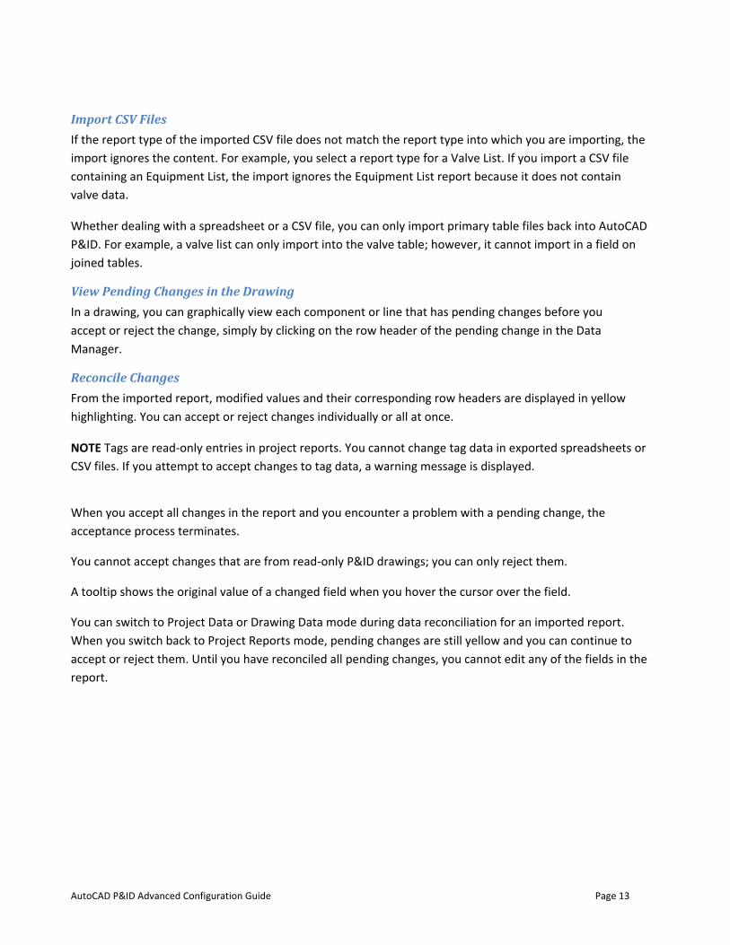
To import aOpen the Dayou want to
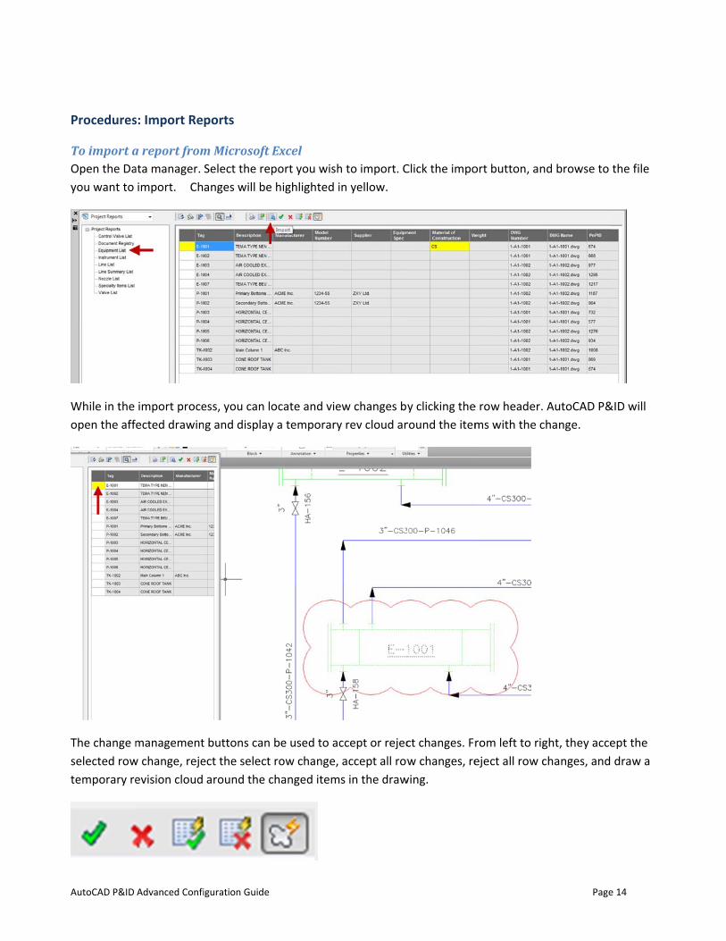
While in the open the aff
The change mselected rowtemporary re
Advanced Confi
s: Import Re
a report fromata manager.
import. Ch
import proceected drawin
managementw change, rejeevision cloud
iguration Guide
ports
m Microsoft Select the repanges will be
ess, you can long and display
t buttons can ect the select
around the c
Excel port you wish highlighted i
ocate and viey a temporary
be used to acrow change,
changed item
h to import. Cin yellow.
ew changes byy rev cloud ar
ccept or rejecaccept all rows in the draw
Click the impo
y clicking theround the item
ct changes. Frw changes, re
wing.
ort button, an
e row header.ms with the c
rom left to rigeject all row c
Page
nd browse to
AutoCAD P&change.
ght, they accechanges, and
e 14
the file
&ID will
ept the draw a
AutoCAD P&ID
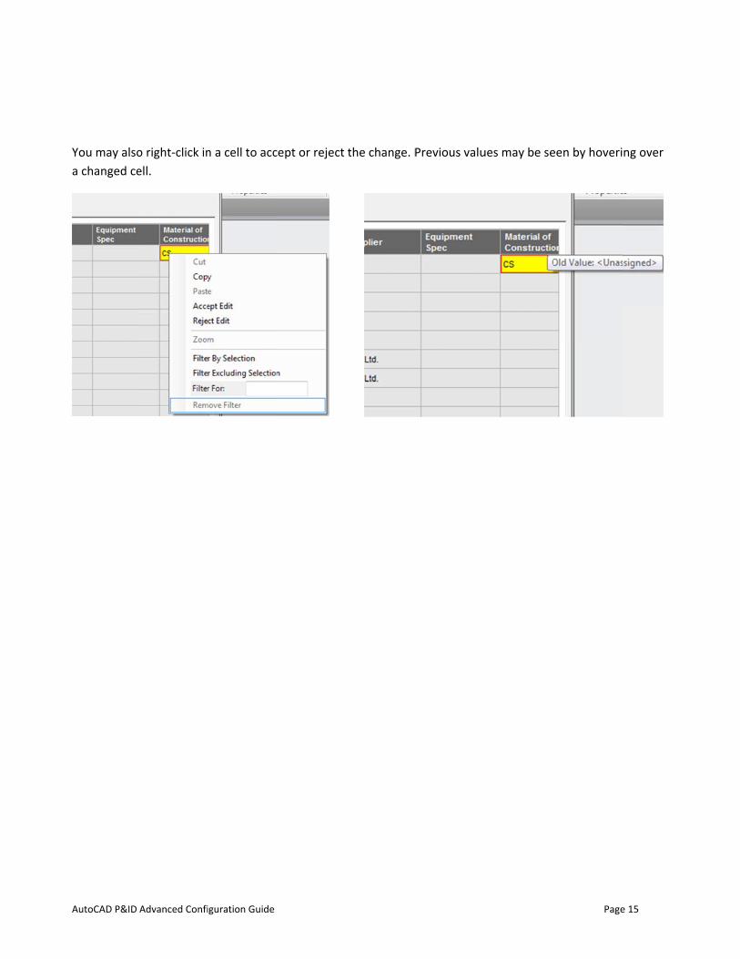
You may alsoa changed ce
Advanced Confi
o right-click inell.
iguration Guide
n a cell to acc
cept or reject the change. PPrevious valuues may be se
Page
een by hoveri
e 15
ng over
AutoCAD P&ID
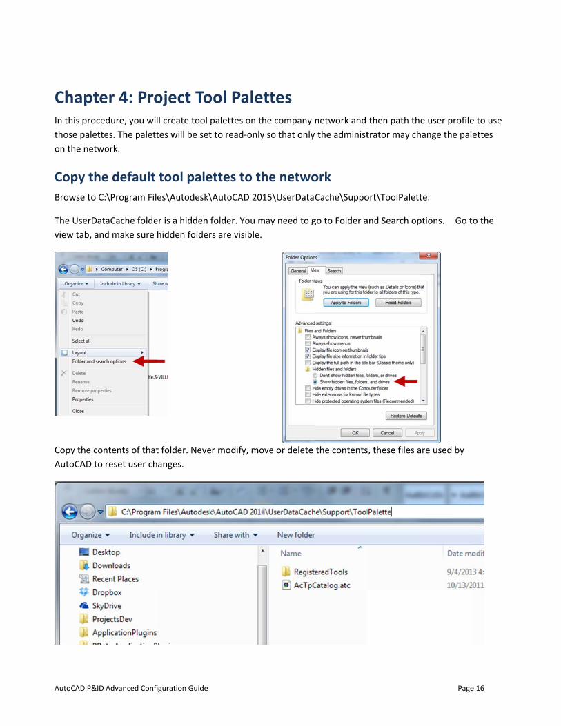
ChapteIn this procethose paletteon the netwo
Copy theBrowse to C:
The UserDatview tab, and
Copy the conAutoCAD to
Advanced Confi
er 4: Produre, you wiles. The palettork.
e default :\Program File
taCache folded make sure
ntents of thatreset user ch
iguration Guide
oject Toll create tool tes will be set
tool palees\Autodesk\
er is a hidden hidden folder
t folder. Neveanges.
ool Palepalettes on tht to read-only
ettes to th\AutoCAD 20
folder. You mrs are visible.
er modify, mo
ettes he company ny so that only
he netwo15\UserData
may need to g
ove or delete
network and y the administ
ork Cache\Suppo
go to Folder a
the contents
then path thtrator may ch
ort\ToolPalett
and Search op
s, these files a
Page
e user profilehange the pal
te.
ptions. Go t
are used by
e 16
e to use ettes
o the
AutoCAD P&ID
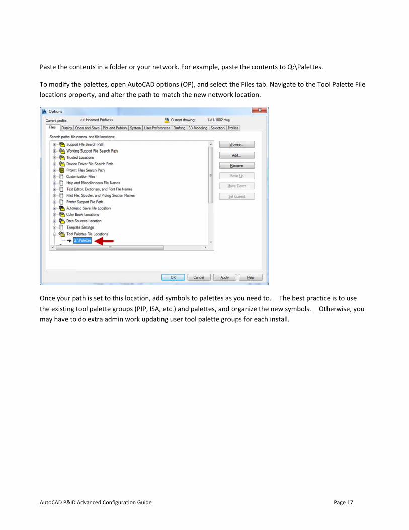
Paste the co
To modify thlocations pro
Once your pathe existing tmay have to
Advanced Confi
ntents in a fo
he palettes, ooperty, and a
ath is set to ttool palette gdo extra adm
iguration Guide
older or your n
pen AutoCADlter the path
his location, agroups (PIP, ISmin work upd
network. For
D options (OPto match the
add symbols SA, etc.) and pating user too
example, pas
), and select te new networ
to palettes aspalettes, and ol palette gro
ste the conte
the Files tab.rk location.
s you need to organize the
oups for each
ents to Q:\Pal
Navigate to t
o. The best e new symbol install.
Page
ettes.
the Tool Pale
practice is tos. Otherwis
e 17
ette File
o use se, you
AutoCAD P&ID
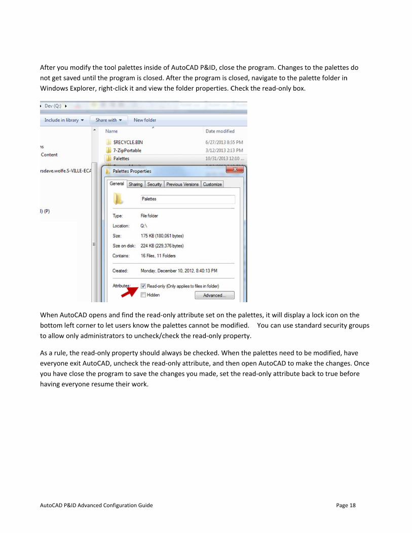
After you monot get saveWindows Ex
When AutoCbottom left cto allow only
As a rule, theeveryone exyou have clohaving every
Advanced Confi
odify the toold until the prplorer, right-c
CAD opens ancorner to let y administrato
e read-only pit AutoCAD, u
ose the prograyone resume
iguration Guide
l palettes insirogram is closclick it and vie
d find the reausers know thors to unchec
roperty shouuncheck the ram to save ththeir work.
de of AutoCAsed. After theew the folder
ad-only attribhe palettes cack/check the
ld always be read-only attrhe changes yo
AD P&ID, close program is cr properties. C
bute set on thannot be modread-only pro
checked. Whribute, and thou made, set t
e the programclosed, navigaCheck the rea
he palettes, itdified. You operty.
hen the paletthen open Autothe read-only
m. Changes toate to the palad-only box.
t will display acan use stand
tes need to beoCAD to maky attribute ba
Page
o the palettesette folder in
a lock icon ondard security
e modified, hke the changeack to true be
e 18
s do n
n the y groups
have es. Once efore
AutoCAD P&ID
Chapte
Symbols
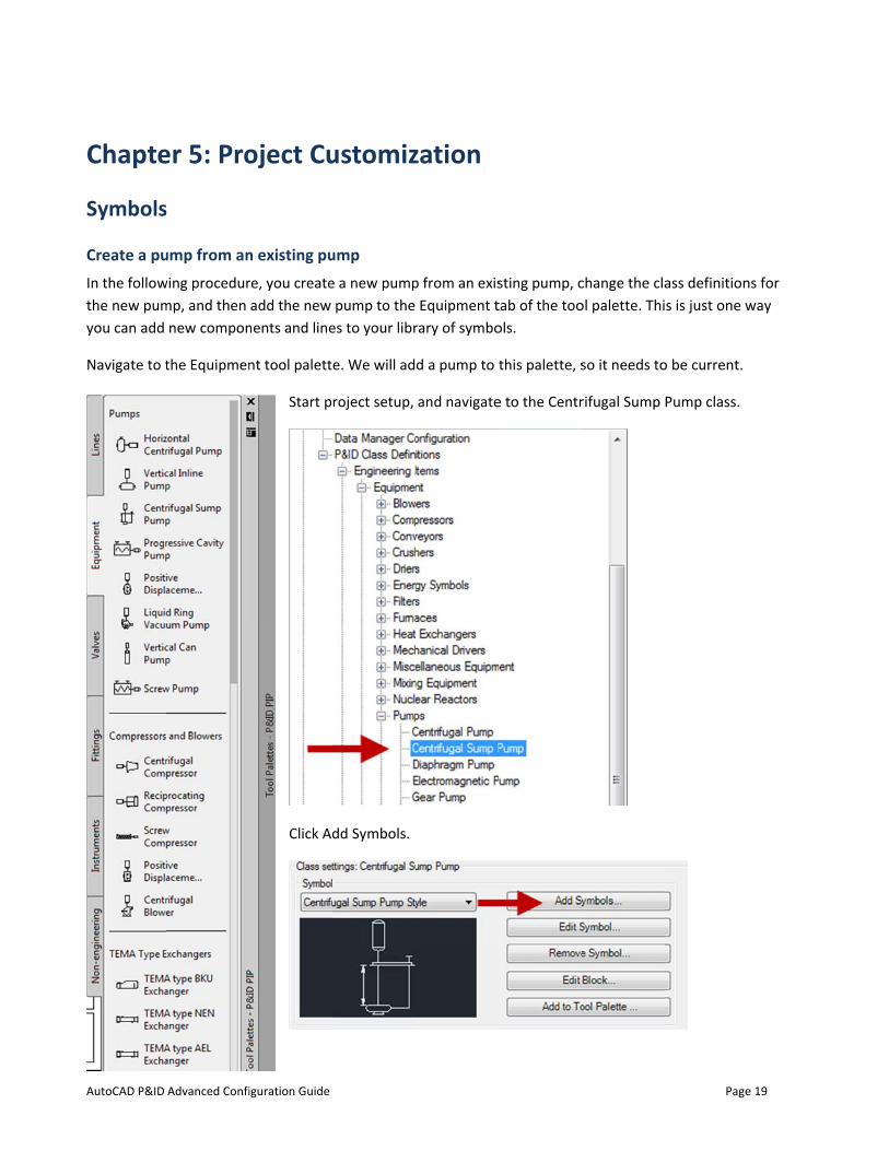
Create a puIn the followthe new pumyou can add
Navigate to t
Advanced Confi
er 5: Pro
s
ump from anwing procedurmp, and then
new compon
the Equipmen
iguration Guide
oject Cu
n existing pure, you createadd the new
nents and line
nt tool palett
Start p
Click Ad
ustomiz
ump e a new pump
pump to the es to your libr
e. We will ad
roject setup,
dd Symbols.
zation
p from an exisEquipment t
rary of symbo
d a pump to t
and navigate
sting pump, ctab of the toools.
this palette, s
e to the Centr
change the claol palette. Thi
so it needs to
rifugal Sump
Page
ass definitions is just one w
o be current.
Pump class.
e 19
ns for way
AutoCAD P&ID
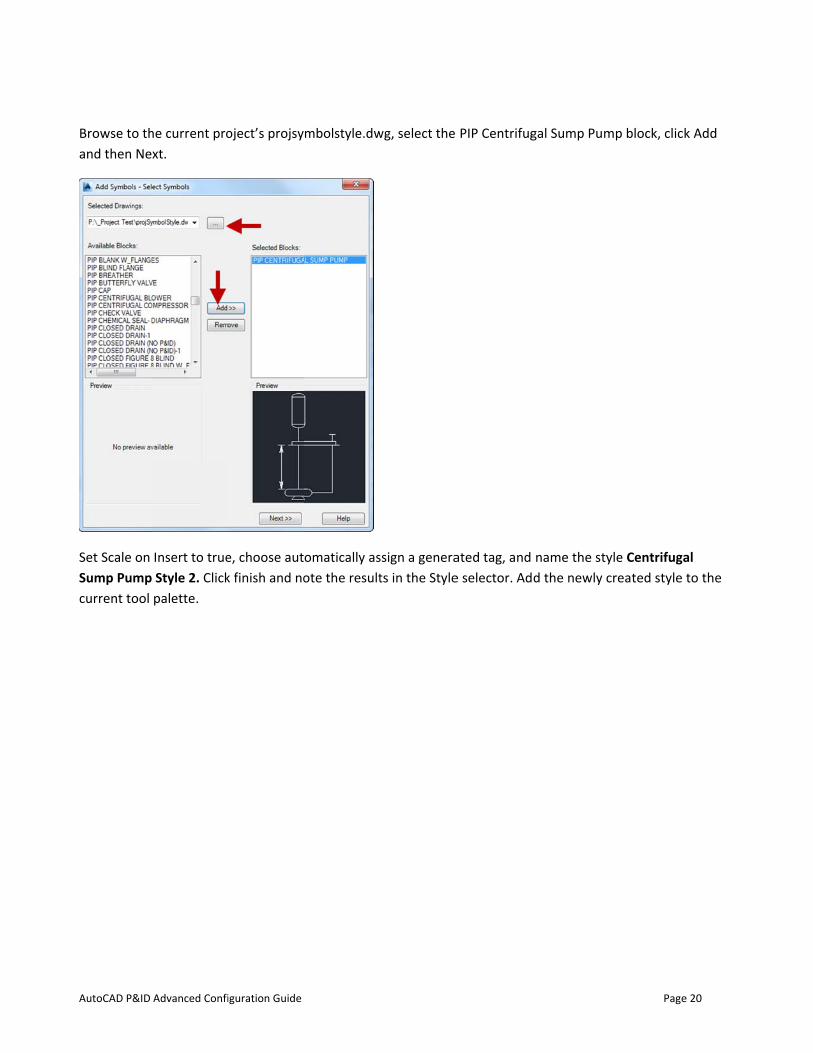
Browse to thand then Ne
Set Scale on Sump Pumpcurrent tool
Advanced Confi
he current proxt.
Insert to trueStyle 2. Clickpalette.
iguration Guide
oject’s projsy
e, choose autk finish and no
mbolstyle.dw
omatically asote the result
wg, select the
ssign a generats in the Style
PIP Centrifug
ated tag, and e selector. Ad
gal Sump Pum
name the styd the newly c
Page
mp block, clic
yle Centrifugacreated style
e 20
k Add
al to the
AutoCAD P&ID
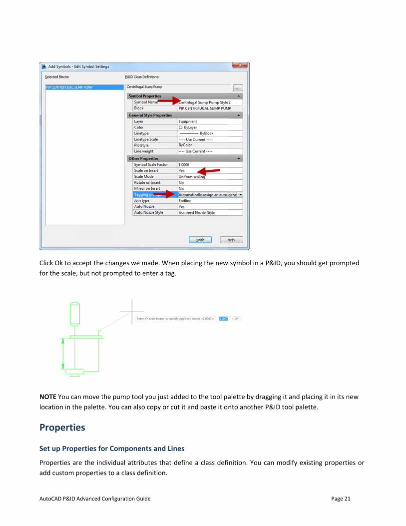
Click Ok to afor the scale
NOTE You calocation in th
Properti
Set up Prop
Properties aadd custom
Advanced Confi
ccept the cha, but not prom
an move the phe palette. Yo
es
perties for C
re the individproperties to
iguration Guide
anges we madmpted to ent
pump tool yoou can also co
omponents
dual attributeo a class defin
de. When plater a tag.
ou just added opy or cut it a
and Lines
es that defineition.
cing the new
to the tool paand paste it o
e a class defi
w symbol in a
alette by dragnto another P
inition. You c
P&ID, you sho
gging it and pP&ID tool pal
can modify ex
Page
ould get prom
placing it in itslette.
xisting prope
e 21
mpted
s new
erties or
AutoCAD P&ID
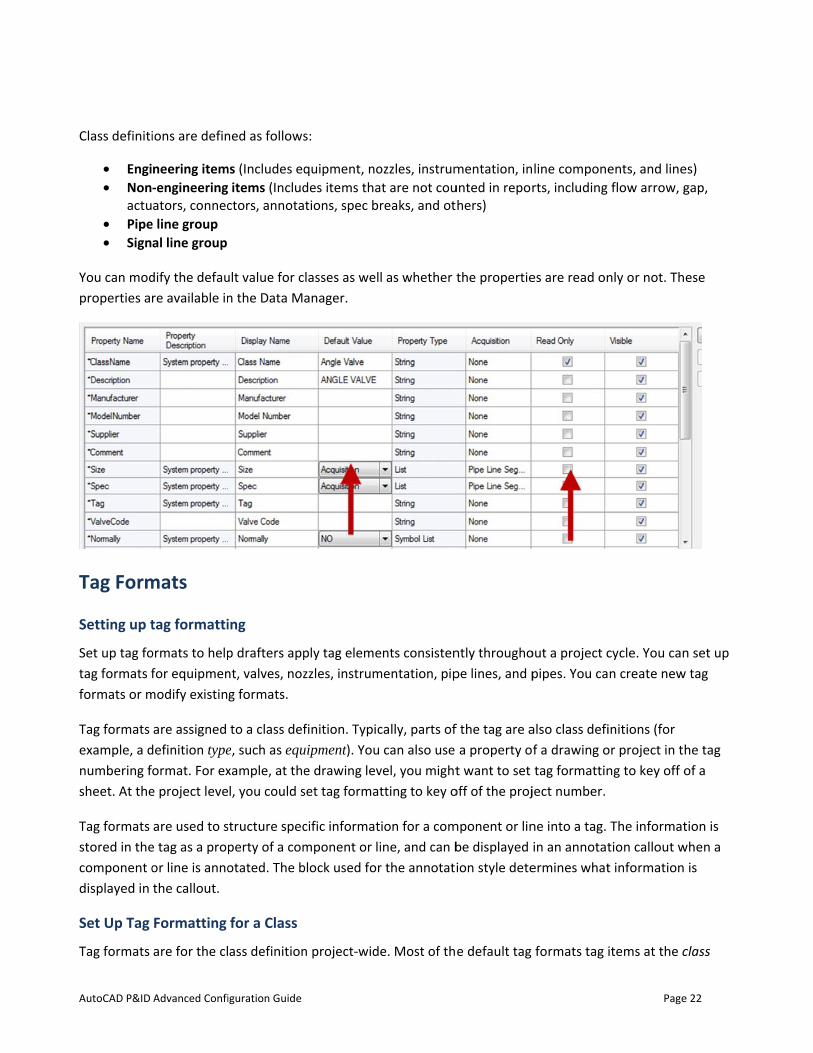
Class definiti
• Engi• Non
actu• Pipe• Sign
You can modproperties a
Tag Form
Setting up t
Set up tag fotag formats fformats or m
Tag formats example, a dnumbering fsheet. At the
Tag formats stored in thecomponent odisplayed in
Set Up Tag
Tag formats
Advanced Confi
ions are defin
neering item-engineeringators, connec
e line group al line group
dify the defaure available in
mats
tag formatti
ormats to helpfor equipmen
modify existin
are assigned definition type
ormat. For exe project leve
are used to se tag as a propor line is annothe callout.
Formatting
are for the cl
iguration Guide
ned as follows
ms (Includes eq items (Includctors, annota
ult value for cn the Data M
ing
p drafters appnt, valves, nozg formats.
to a class defe, such as equ
xample, at thel, you could s
structure specperty of a comotated. The b
for a Class
ass definition
s:
quipment, nodes items thations, spec br
lasses as welanager.
ply tag elemezzles, instrum
finition. Typicuipment). You e drawing levset tag format
cific informatmponent or liblock used for
n project-wid
ozzles, instrumat are not coureaks, and ot
l as whether t
ents consistenmentation, pip
cally, parts ofcan also use
vel, you mighttting to key o
ion for a comine, and can br the annotati
e. Most of th
mentation, inunted in reporhers)
the propertie
ntly throughope lines, and p
f the tag are aa property o
t want to set off of the proj
mponent or linbe displayed ion style dete
e default tag
line componerts, including
es are read on
out a project cpipes. You ca
also class defif a drawing otag formattin
ject number.
ne into a tag. in an annotat
ermines what
formats tag i
Page
ents, and lineflow arrow, g
nly or not. Th
cycle. You cann create new
initions (for or project in tng to key off o
The informattion callout wt information
items at the c
e 22
es) gap,
ese
n set up w tag
he tag of a
tion is when a
is
class
AutoCAD P&ID Advanced Configuration Guide Page 23
definition level (for example, a class definition type, such as equipment). You can use the property of the class, of a drawing, or of the project in the tag numbering format. At the drawing level, you might want to set tag formatting to key off of a sheet. At the project level, you could set tag formatting to key off of the project number.
Set Up Tag Formatting Using Acquiring Properties
Tag formats can include properties that acquire their values from other properties. For example, if a line acquires its Unit value from a project-level property, you can use that acquiring property in the line’s tag format. If the Unit value at the project level were to change, all tags with that property as a subpart would update to reflect that change.
Set Up Tag Formatting for a Pipe Line Group
Pipes are the only components that are automatically grouped. Although Pipe Line Groups are constructs rather than physical entities, you set up tag formatting for Pipe Line Groups just as you would for any other component.
The default tag format is Line Number, and you can add other properties as needed, for example Service.
Understand Default Tag Formatting Templates
AutoCAD P&ID provides the following tag format templates for you to use or modify to fit with your company tag formatting standards:
• Equipment tag (Type-Number). Defined by default with a type property and a number (for example: P-100).
• Equipment tag 2 (Area-Type-Number). Defined by default with an area property, type property, and number (for example: 25-P-1000).
• Hand valve tag (Code-Number). Defined by default with two letters representing a valve code and a number (for example: HV-100).
• Nozzle tag (N-Number). Defined by default with one or more letters representing a nozzle code and a number (for example: N-1).
• Instrumentation tag (Area-Type-Number). Defined by default with an area, type, and loop number (for example: 51-PT-100).
• Line number tag. Defined by default with a line number (for example: 100). • Pipeline tag (Size-Spec-Service-Line Number). Defined by default with size value, spec, service, and
line number (for example: 6"-C1-P-10014).
Build Tag Formatting Expressions
You can define how tag elements are expressed. For example, you can create an instrument tag of Area-Type-Loop Number_Suffix (25-FE-1002_A). As you define the formatting for a tag, you can control the formatting of the values that can be assigned when tagging a component or line through expressions.
AutoCAD P&ID Advanced Configuration Guide Page 24
Using expressions, you can designate whether a value must be entered as text characters, numbers, or any combination of text characters and numbers (free-style value). When you enter a value while assigning a tag, you can also define an expression to generate a value automatically when a drafter adds a component to a drawing. You can set automatic expressions to a drawing or project property.
Understand Tag Uniqueness
The entire tag property must be unique. Even items of different types must have unique tags. For example, if you assign the tag A-123 to a pump, you cannot assign the identical tag to a tank.
Line segments tags are an exception to this rule and can be identical. The tag properties of a line group must be unique, but the tag properties of the line segments within that line group can be the same.
Another exception to this rule allows you to tag a large component that stretches across drawings with duplicate tags. Duplicate tags can represent different parts of the same item. For example, a line that spans drawings using an Off Page Connector can have the same tag in each drawing. The Data Manager has a single row for components that span two drawings.
AutoCAD P&ID
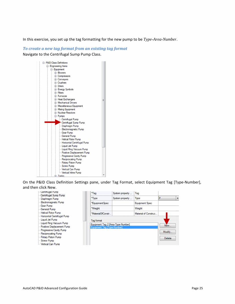
In this exerci
To create a Navigate to t
On the P&IDand then clic
Advanced Confi
ise, you set u
new tag forthe Centrifug
D Class Definick New.
iguration Guide
p the tag form
rmat from angal Sump Pum
ition Settings
matting for th
n existing tamp Class.
s pane, under
he new pump
ag format
r Tag Format
p to be Type-A
t, select Equi
Area-Number
pment Tag [T
Page
r.
Type-Number
e 25
r],
AutoCAD P&ID
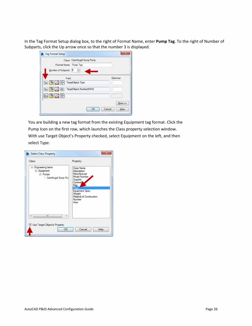
In the Tag FoSubparts, clic
You are buPump IconWith use Tselect Type
Advanced Confi
ormat Setup dck the Up arr
uilding a new n on the first rTarget Object’e.
iguration Guide
dialog box, toow once so t
tag format frrow, which la’s Property ch
o the right of Fhat the numb
rom the existiunches the Checked, selec
Format Nameber 3 is displa
ing EquipmenClass propertyct Equipment
e, enter Pumpayed.
nt tag formaty selection wion the left, a
p Tag. To the
. Click the indow. and then
Page
right of Num
e 26
mber of
AutoCAD P&ID
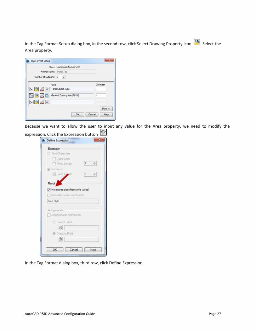
In the Tag FoArea propert
Because we
expression. C
In the Tag Fo
Advanced Confi
ormat Setup dty.
want to all
Click the Expr
ormat dialog b
iguration Guide
dialog box, in
ow the user
ression butto
box, third row
the second r
r to input an
n .
w, click Define
row, click Sele
ny value for
e Expression.
ect Drawing P
the Area pr
Property icon
operty, we n
Page
. Select t
need to mod
e 27
the
dify the
AutoCAD P&ID
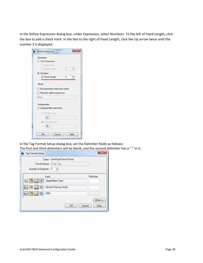
In the Definethe box to adnumber 3 is
In the Tag FoThe first and
Advanced Confi
e Expression ddd a check mdisplayed.
ormat Setup dd third delimit
iguration Guide
dialog box, unark. In the bo
dialog box, seters will be bl
nder Expressiox to the right
et the Delimitank, and the
on, select Nut of Fixed Len
er fields as fosecond delim
umbers. To thngth, click the
ollows: miter has a “.”
he left of Fixede Up arrow tw
” In it.
Page
d Length, clicwice until the
e 28
ck
AutoCAD P&ID
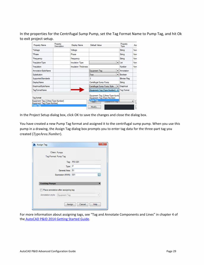
In the propeto exit proje
In the Projec
You have crepump in a drcreated (Typ
For more infthe AutoCAD
Advanced Confi
erties for theect setup.
ct Setup dialo
eated a new Prawing, the ApeArea.Numbe
formation aboD P&ID 2014 G
iguration Guide
e Centrifuga
g box, click O
Pump Tag forssign Tag diaer).
out assigning Getting Starte
al Sump Pum
OK to save the
mat and assiglog box prom
tags, see “Taed Guide.
mp, set the T
e changes and
gned it to thempts you to en
ag and Annota
ag Format N
d close the di
e centrifugal snter tag data
ate Compone
Name to Pum
alog box.
sump pump. Wfor the three
ents and Lines
Page
mp Tag, and
When you us-part tag you
s” in chapter
e 29
hit Ok
se this u
4 of
AutoCAD P&ID
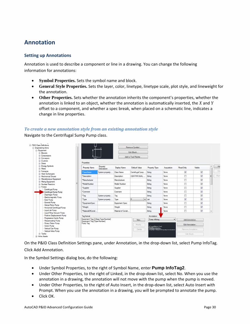
Annotat
Setting up A
Annotation iinformation
• Sym• Gen
the a• Othe
annooffsechan
To create a Navigate to t
On the P&IDClick Add An
In the Symbo
• Und• Und
anno• Und
Prom• Click
Advanced Confi
ion
Annotations
s used to desfor annotatio
mbol Propertineral Style Prannotation. er Propertiesotation is linket to a componge in line pro
new annotathe Centrifug
D Class Definitnotation.
ol Settings dia
er Symbol Proer Other Propotation in a der Other Prop
mpt. When yok OK.
iguration Guide
s
scribe a compons:
ies. Sets the sroperties. Set
s. Sets whethked to an objeonent, and whoperties.
ation style frgal Sump Pum
tion Settings p
alog box, do t
operties, to tperties, to therawing, the aperties, to theou use the an
ponent or line
symbol namets the layer, c
her the annotect, whether thether a spec
rom an existmp class.
pane, under A
the following
he right of Sye right of Link
annotation wie right of Autnotation in a
e in a drawing
and block. color, linetype
ation inheritsthe annotatioc break, when
ting annotat
Annotation, in
:
ymbol Name, ked, in the droll not move wo Insert, in thdrawing, you
g. You can cha
e, linetype sca
s the componon is automatn placed on a
tion style
n the drop-do
enter Pumpop-down list,
with the pumhe drop-downu will be prom
ange the follo
ale, plot style
nent’s properttically inserteschematic lin
own list, selec
p InfoTag2. , select No. Wp when the pn list, select Ampted to ann
Page
owing
e, and linewei
ties, whethered, the X and ne, indicates
ct Pump InfoT
When you use pump is moveAuto Insert wiotate the pum
e 30
ight for
r the Y a
Tag.
the ed. ith mp.
AutoCAD P&ID
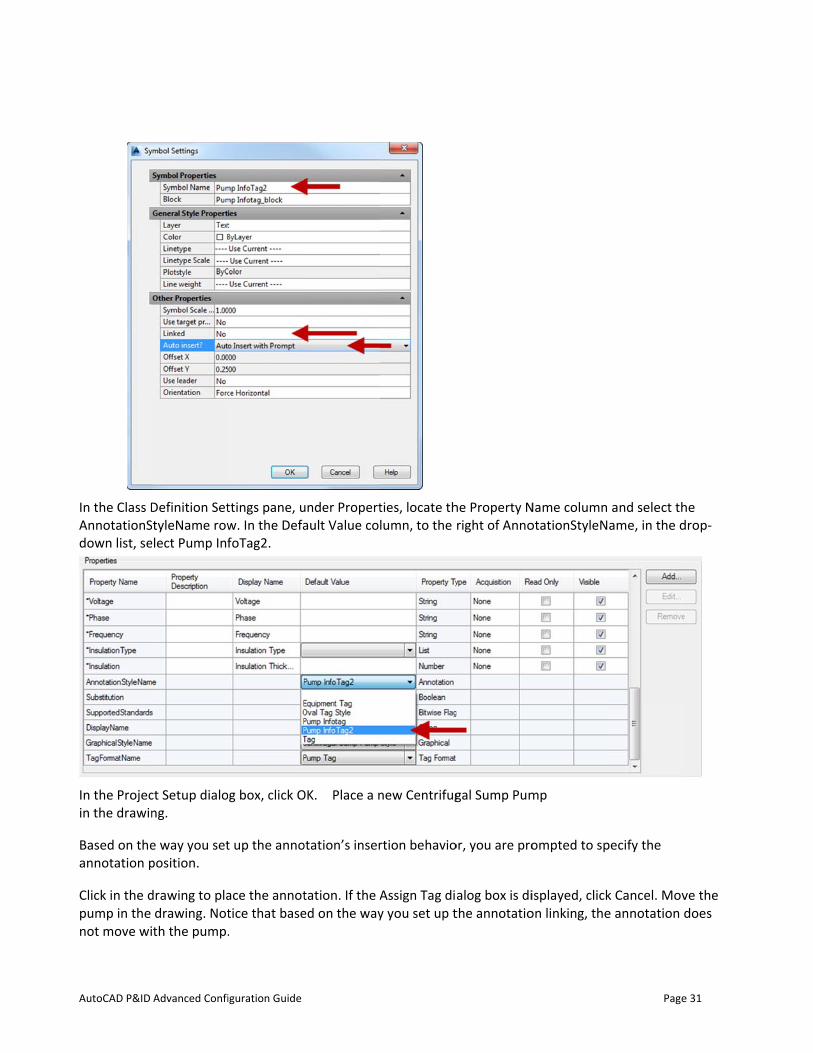
In the Class DAnnotationSdown list, se
In the Projecin the drawin
Based on theannotation p
Click in the dpump in the not move wi
Advanced Confi
Definition SettyleName row
elect Pump Inf
ct Setup dialong.
e way you setposition.
drawing to pladrawing. Notth the pump.
iguration Guide
ttings pane, uw. In the DefafoTag2.
g box, click O
t up the anno
ace the annottice that base.
under Propertault Value co
OK. Place a n
otation’s inser
tation. If the Aed on the way
ties, locate thlumn, to the
new Centrifug
rtion behavio
Assign Tag diy you set up t
he Property Nright of Anno
gal Sump Pum
or, you are pro
alog box is dithe annotatio
Name column otationStyleN
mp
ompted to sp
isplayed, clickon linking, the
Page
and select thame, in the d
pecify the
k Cancel. Move annotation d
e 31
he drop-
ve the does
AutoCAD P&ID
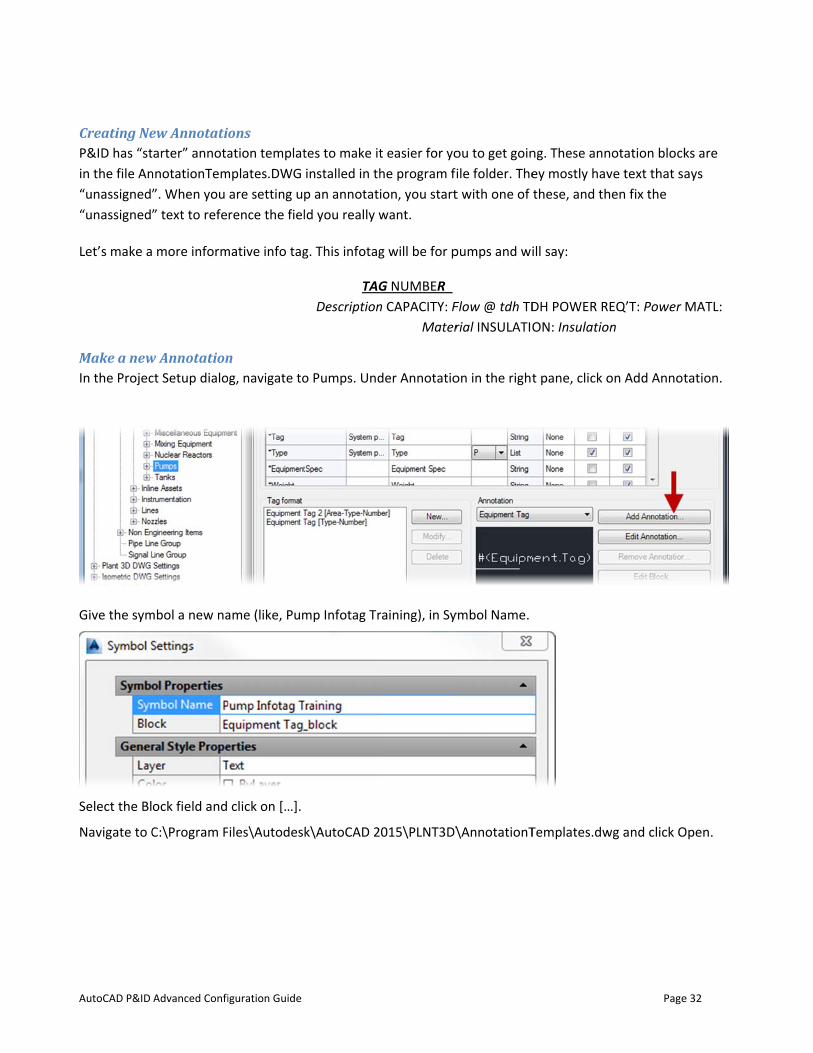
Creating NeP&ID has “stin the file An“unassigned”“unassigned”
Let’s make a
Make a newIn the Projec
Give the sym
Select the Bl
Navigate to C
Advanced Confi
ew Annotatitarter” annotannotationTem”. When you ” text to refe
more inform
w Annotationct Setup dialo
mbol a new na
ock field and
C:\Program F
iguration Guide
ons ation templat
mplates.DWG are setting urence the fiel
mative info tag
n g, navigate to
ame (like, Pum
click on […].
iles\Autodes
tes to make itinstalled in thp an annotatild you really w
g. This infotag
TAGDescription
o Pumps. Und
mp Infotag Tr
k\AutoCAD 2
t easier for yohe program fiion, you startwant.
g will be for p
G NUMBER n CAPACITY: F
Mater
der Annotatio
raining), in Sy
015\PLNT3D\
ou to get goinile folder. Thet with one of
pumps and wi
Flow @ tdh TDrial INSULATIO
on in the right
ymbol Name.
\AnnotationT
ng. These anney mostly havthese, and th
ill say:
DH POWER RON: Insulatio
t pane, click o
Templates.dw
Page
notation blockve text that sahen fix the
EQ’T: Power on
on Add Annot
wg and click O
e 32
ks are ays
MATL:
tation.
Open.
AutoCAD P&ID
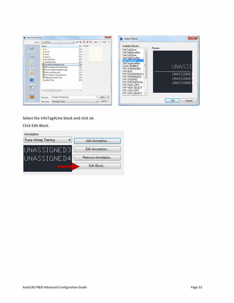
Select the In
Click Edit Blo
Advanced Confi
foTag4Line b
ock.
iguration Guide
lock and clickk ok.
Pagee 33
AutoCAD P&ID
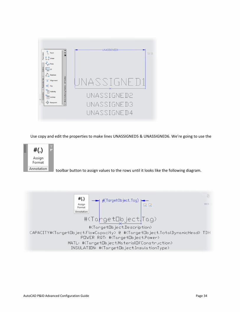
Use copy
Advanced Confi
y and edit the
toolba
iguration Guide
e properties t
r button to as
to make lines
ssign values t
UNASSIGNED
to the rows un
D5 & UNASSIG
ntil it looks lik
GNED6. We’r
ke the follow
Page
re going to us
ing diagram.
e 34
se the
AutoCAD P&ID
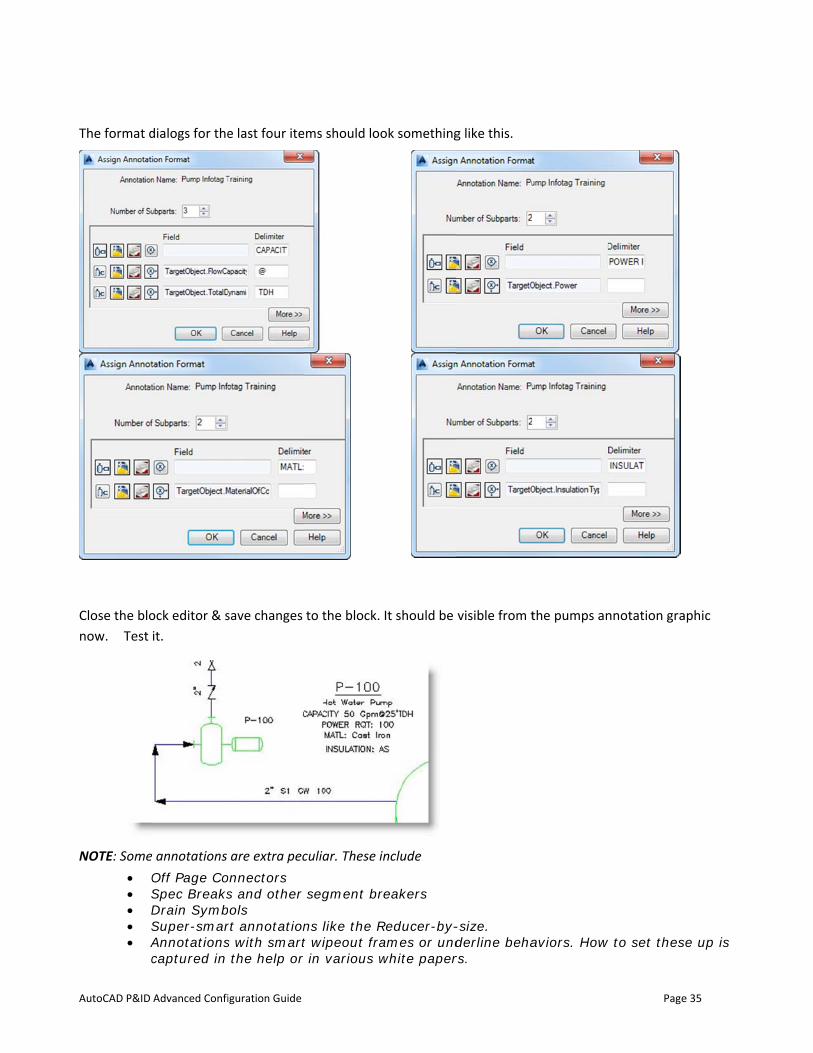
The format d
Close the blonow. Test
NOTE: Some• O• S• D• S• A
c
Advanced Confi
dialogs for the
ock editor & sit.
annotations Off Page CoSpec BreaksDrain SymbSuper-smarAnnotationscaptured in
iguration Guide
e last four ite
save changes
are extra peconnectors s and other
bols rt annotations with smartthe help or
ems should lo
to the block.
culiar. These i
segment br
ns like the Rt wipeout frar in various w
ok something
It should be
include
reakers
Reducer-by-ames or undwhite paper
g like this.
visible from t
-size. derline behars.
the pumps an
aviors. How
Page
nnotation gra
w to set thes
e 35
aphic
se up is
AutoCAD P&ID
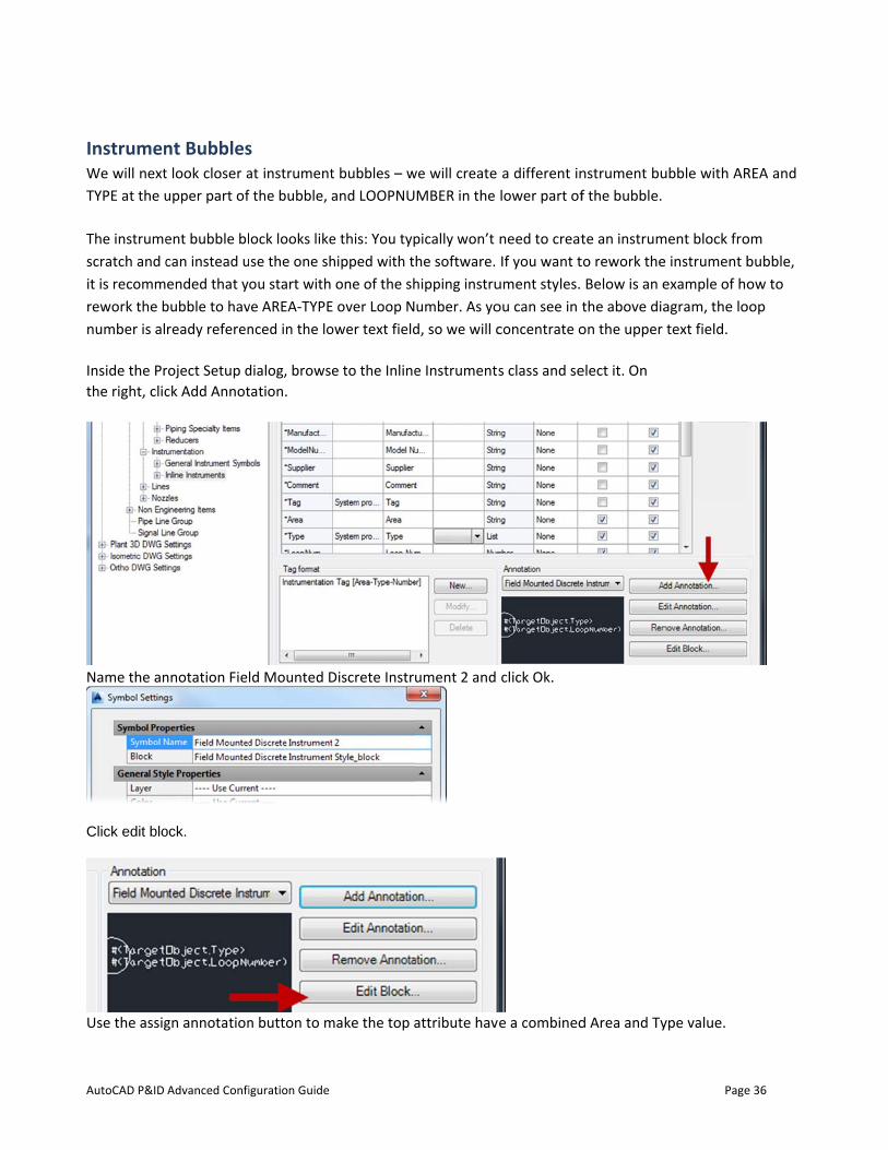
InstrumenWe will nextTYPE at the u
The instrumescratch and cit is recommrework the bnumber is al
Inside the Prthe right, clic
Name the an
Click edit blo
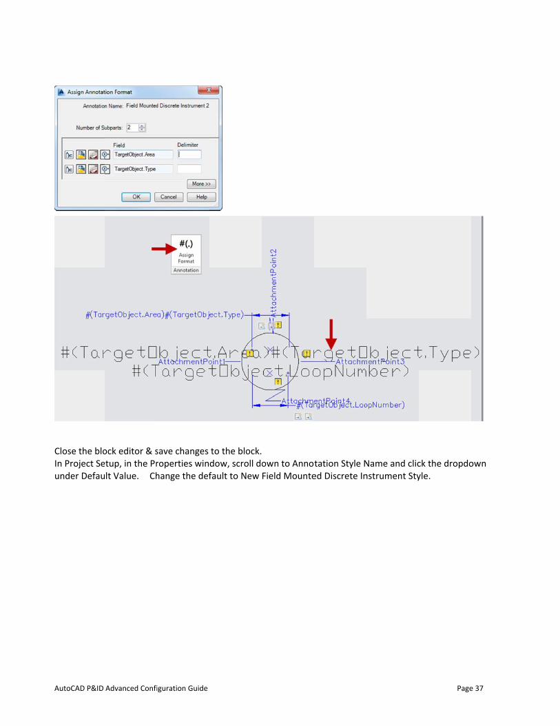
Use the assig
Advanced Confi
nt Bubblest look closer aupper part of
ent bubble blcan instead uended that y
bubble to havready referen
roject Setup dck Add Annot
nnotation Fiel
ock.
gn annotation
iguration Guide
s at instrumentf the bubble, a
ock looks likese the one shou start with
ve AREA-TYPEnced in the lo
dialog, browsetation.
ld Mounted D
n button to m
t bubbles – wand LOOPNU
e this: You typhipped with tone of the sh
E over Loop Nower text field
e to the Inline
Discrete Instru
make the top a
we will create MBER in the
pically won’t he software. hipping instruumber. As yod, so we will c
e Instruments
ument 2 and
attribute hav
a different inlower part of
need to creatIf you want t
ument styles. ou can see in concentrate o
s class and se
click Ok.
e a combined
nstrument buf the bubble.
te an instrumto rework the
Below is an ethe above diaon the upper
elect it. On
d Area and Ty
Page
ubble with AR
ment block froe instrument bexample of hoagram, the lotext field.
ype value.
e 36
REA and
om bubble, ow to
oop
AutoCAD P&ID
Close the bloIn Project Seunder Defau
Advanced Confi
ock editor & setup, in the Pr
lt Value. Ch
iguration Guide
save changes roperties winhange the def
to the block.dow, scroll dofault to New
own to AnnotField Mounte
tation Style Ned Discrete In
Name and clicnstrument Sty
Page
ck the dropdoyle.
e 37
own
AutoCAD P&ID
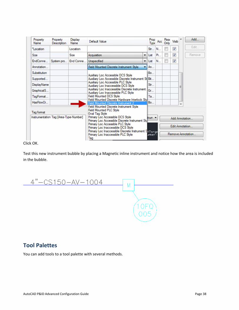
Click OK.
Test this newin the bubble
Tool PaleYou can add
Advanced Confi
w instrument e.
ettes tools to a too
iguration Guide
bubble by pla
ol palette wit
acing a Magn
h several me
netic inline ins
thods.
strument andd notice how
Page
the area is in
e 38
cluded
AutoCAD P&ID
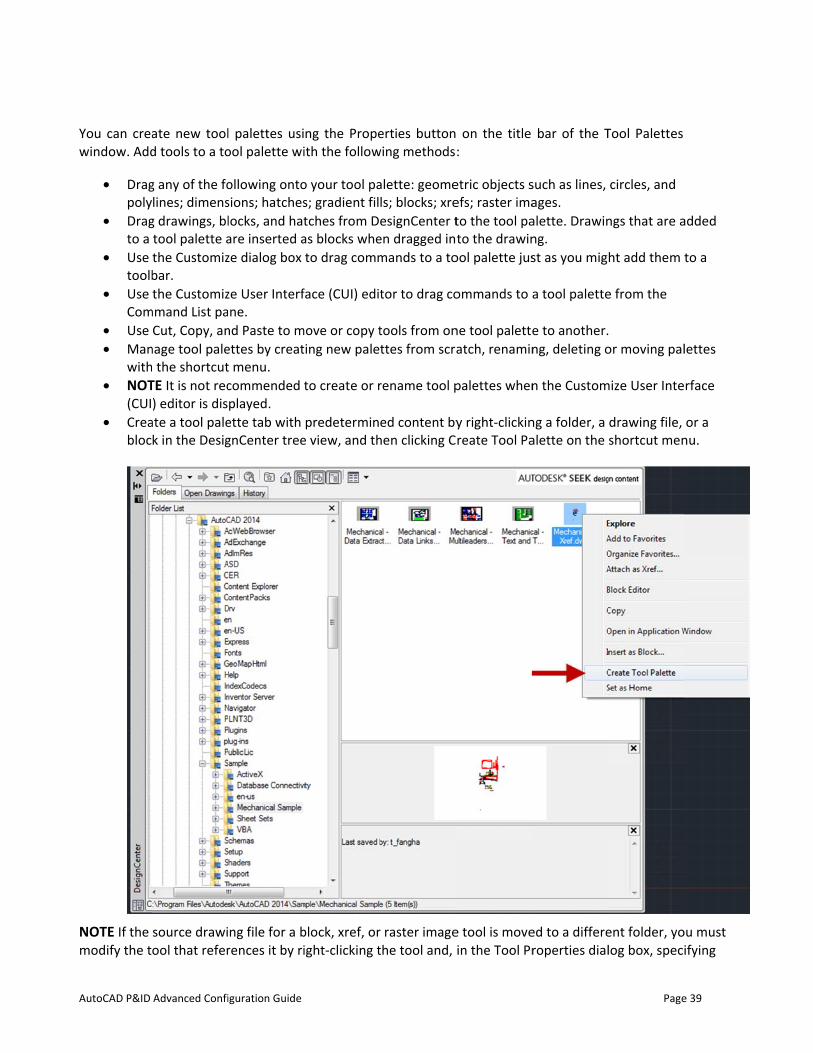
You can creawindow. Add
• Dragpoly
• Dragto a
• Use toolb
• Use Com
• Use • Man
with• NOT
(CUI• Crea
bloc
NOTE If the modify the t
Advanced Confi
ate new toold tools to a to
g any of the folines; dimens
g drawings, bltool palette athe Customizbar. the Customiz
mmand List paCut, Copy, an
nage tool pale the shortcut
TE It is not rec) editor is dis
ate a tool palek in the Desig
source drawiool that refer
iguration Guide
l palettes usiool palette wi
ollowing ontosions; hatcheslocks, and hatare inserted aze dialog box
ze User Interfne.
nd Paste to mettes by creatt menu. commended tplayed.
ette tab with gnCenter tree
ng file for a brences it by ri
ng the Propeith the follow
o your tool pas; gradient filtches from Das blocks wheto drag comm
face (CUI) edit
move or copy tting new palet
to create or r
predetermine view, and th
block, xref, oright-clicking t
erties buttonwing methods
alette: geomels; blocks; xreesignCenter t
en dragged inmands to a to
tor to drag co
tools from onttes from scra
rename tool p
ed content byhen clicking C
r raster imagethe tool and,
on the title :
etric objects sefs; raster imato the tool pato the drawin
ool palette jus
ommands to a
ne tool paletteatch, renamin
palettes when
y right-clickinreate Tool Pa
e tool is movein the Tool Pr
bar of the T
such as lines, ages. alette. Drawinng. st as you mig
a tool palette
e to another.ng, deleting o
n the Custom
ng a folder, a alette on the
ed to a differeroperties dial
Page
Tool Palettes
circles, and
ngs that are a
ht add them t
e from the
or moving pal
mize User Inte
drawing file, shortcut men
ent folder, yolog box, speci
e 39
added
to a
lettes
rface
or a nu.
ou must ifying
AutoCAD P&ID
the new sou
RearrangingOnce tools athem. You ca
You can movTool PalettesTool palettesthe path to ylocation.
Sharing pBecause Autoptions for s To share indretain all of t
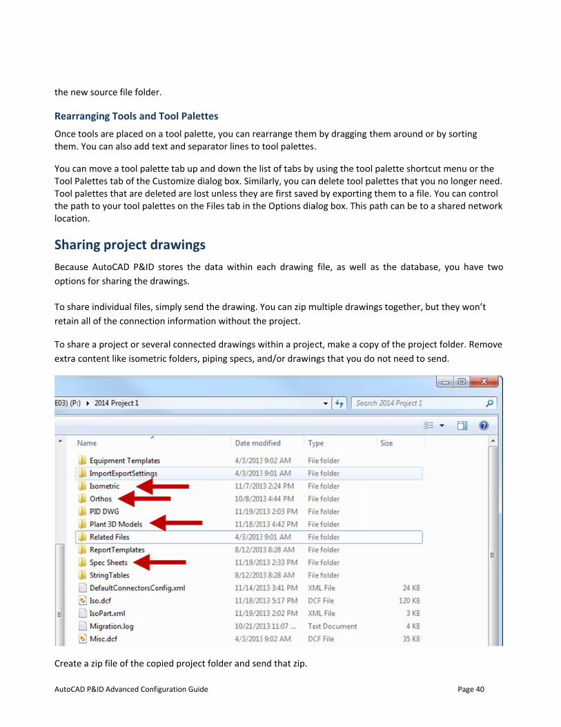
To share a pextra conten
Create a zip
Advanced Confi
rce file folder
g Tools and re placed on
an also add te
ve a tool pales tab of the Cs that are delyour tool pale
project dtoCAD P&ID sharing the dr
ividual files, sthe connectio
roject or sevent like isometr
file of the cop
iguration Guide
r.
Tool Palettea tool palette
ext and separ
tte tab up anustomize diaeted are lost
ettes on the F
rawings stores the d
rawings.
simply send ton informatio
eral connecteric folders, pi
pied project f
es e, you can rearator lines to t
d down the lilog box. Similunless they a
Files tab in the
ata within ea
he drawing. Yon without the
ed drawings wping specs, a
folder and sen
arrange themtool palettes.
ist of tabs by larly, you canare first savede Options dia
ach drawing
You can zip me project.
within a projend/or drawin
nd that zip.
m by dragging .
using the toon delete tool pd by exportingalog box. This
file, as well
multiple drawi
ct, make a congs that you d
them around
ol palette shopalettes that g them to a fpath can be
as the datab
ings together
opy of the prodo not need t
Page
d or by sortin
ortcut menu oyou no longeile. You can cto a shared n
base, you ha
r, but they wo
oject folder. Ro send.
e 40
g
or the er need. control network
ave two
on’t
Remove
AutoCAD P&ID Advanced Configuration Guide Page 41
Chapter 6: Printing Project drawings
Plotting
Plotter Manager
The Plotter Manager is a window that lists plotter configuration (PC3) files for every non-system printer that
you install. Plotter configuration files can also be created for Windows®
system printers if you want to use default properties different from those used by Windows. Plotter configuration settings specify port information, raster and vector graphics quality, paper sizes, and custom properties that depend on the plotter type.
The Plotter Manager contains the Add-a-Plotter wizard, which is the primary tool for creating plotter configurations. The Add-a-Plotter wizard prompts you for information about the plotter you want to set up.
Layouts
A layout represents a plotted page. You can create as many layouts as you need. Each layout is saved on its own layout tab and can be associated with a different page setup.
Elements that appear only on a plotted page, such as title blocks and notes, are drawn in paper space in a layout. The objects in the drawing are created in model space on the Model tab. To view these objects in the layout, you create layout viewports.
Page Setups
When you create a layout, you specify a plotter and settings such as page size and plot orientation. These settings are saved in a page setup. You can control these settings for layouts and for the Model tab using the Page Setup Manager. You can name and save page setups for use with other layouts.
If you don't specify all the settings in the Page Setup dialog box when you create a layout, you can set up the page just before you plot. Or you can override a page setup at plot time. You can use the new page setup temporarily for the current plot, or you can save the new page setup.
Plot Styles
A plot style controls how an object or layer is plotted by determining plotted properties such as lineweight, color, and fill style. Plot style tables collect groups of plot styles. The Plot Style Manager is a window that shows all the plot style tables available.
There are two plot style types: color-dependent and named. A drawing can use only one type of plot style table. You can convert a plot style table from one type to the other. You can also change the type of plot style table a drawing uses once it has been set. For color‐dependent plot style tables, an object's color determines how it is plotted. These plot style table
AutoCAD P&ID
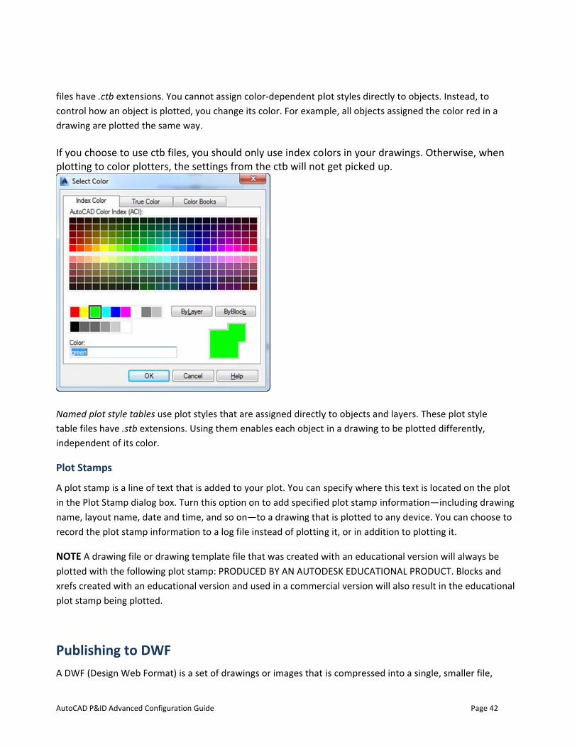
files have .ctcontrol how drawing are If you choosplotting to c
Named plot stable files haindependent
Plot Stamp
A plot stampin the Plot Stname, layourecord the p
NOTE A drawplotted withxrefs createdplot stamp b
PublishinA DWF (Desi
Advanced Confi
tb extensionsan object is pplotted the s
se to use ctbcolor plotter
style tables uave .stb extent of its color.
s
p is a line of tetamp dialog bt name, date lot stamp info
wing file or drthe following
d with an edubeing plotted.
ng to DWgn Web Form
iguration Guide
. You cannot plotted, you came way.
b files, you srs, the settin
use plot stylesnsions. Using t
ext that is addbox. Turn this
and time, anormation to a
rawing templg plot stamp:
ucational vers.
WF mat) is a set o
assign color-dchange its col
hould only ungs from the
s that are assithem enables
ded to your ps option on tod so on—to a
a log file inste
ate file that w PRODUCED B
sion and used
f drawings or
dependent plor. For exam
use index coe ctb will not
igned directlys each object
plot. You can so add specifiea drawing thaead of plottin
was created wBY AN AUTOD in a commer
r images that
lot styles direple, all object
lors in your t get picked
y to objects at in a drawing
specify whered plot stamp
at is plotted tog it, or in add
with an educaDESK EDUCATrcial version w
is compresse
ectly to objectts assigned th
drawings. Oup.
nd layers. Thg to be plotted
e this text is linformation—o any device.
dition to plott
ational versioTIONAL PRODwill also resul
ed into a sing
Page
ts. Instead, tohe color red in
Otherwise, w
ese plot styled differently,
ocated on th—including d. You can choting it.
on will alwaysDUCT. Blocks alt in the educ
le, smaller file
e 42
o n a
when
e
e plot rawing ose to
be and ational
e,
AutoCAD P&ID Advanced Configuration Guide Page 43
making sharing across the Web fast and secure.
Much like Adobe®PDF, the sheets within the set are images of the drawings and are not any more editable than drawings printed to paper. In addition, DWF files retain design information and scale, and are therefore suitable for architects, engineers, and designers to review and mark up, without risk of changes to the original DWG file.
Publishing a P&ID DWF file is very similar to publishing a sheet set in AutoCAD. From the Project manager, you can publish an entire project, a subset of a project, or a single drawing that is part of a project.
To publish a DWF file, use any one of the following methods:
• Click Application menu ➤ Publish. • In the Project Manager, right-click the project folder. Click Publish Dialog Box. • At the Command prompt, enter PUBLISH.
If you plot to a DWF file instead of using the publishing process, you cannot choose P&ID DWF options. NOTE P&ID information is published only for drawings that are part of the current project. You can add drawings from other projects, but P&ID information is not included for those drawings.
AutoCAD P&ID Advanced Configuration Guide Page 44
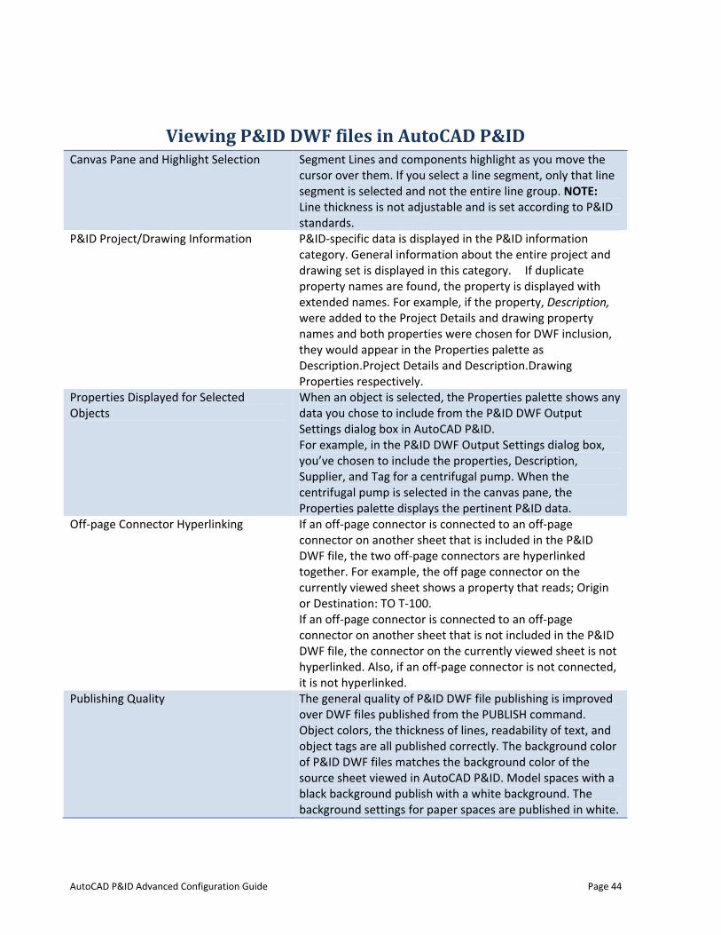
Viewing P&ID DWF files in AutoCAD P&ID Canvas Pane and Highlight Selection Segment Lines and components highlight as you move the
cursor over them. If you select a line segment, only that line segment is selected and not the entire line group. NOTE: Line thickness is not adjustable and is set according to P&ID standards.
P&ID Project/Drawing Information P&ID-specific data is displayed in the P&ID information category. General information about the entire project and drawing set is displayed in this category. If duplicate property names are found, the property is displayed with extended names. For example, if the property, Description, were added to the Project Details and drawing property names and both properties were chosen for DWF inclusion, they would appear in the Properties palette as Description.Project Details and Description.Drawing Properties respectively.
Properties Displayed for Selected Objects
When an object is selected, the Properties palette shows any data you chose to include from the P&ID DWF Output Settings dialog box in AutoCAD P&ID. For example, in the P&ID DWF Output Settings dialog box, you’ve chosen to include the properties, Description, Supplier, and Tag for a centrifugal pump. When the centrifugal pump is selected in the canvas pane, the Properties palette displays the pertinent P&ID data.
Off-page Connector Hyperlinking If an off-page connector is connected to an off-page connector on another sheet that is included in the P&ID DWF file, the two off-page connectors are hyperlinked together. For example, the off page connector on the currently viewed sheet shows a property that reads; Origin or Destination: TO T-100. If an off-page connector is connected to an off-page connector on another sheet that is not included in the P&ID DWF file, the connector on the currently viewed sheet is not hyperlinked. Also, if an off-page connector is not connected, it is not hyperlinked.
Publishing Quality The general quality of P&ID DWF file publishing is improved over DWF files published from the PUBLISH command. Object colors, the thickness of lines, readability of text, and object tags are all published correctly. The background color of P&ID DWF files matches the background color of the source sheet viewed in AutoCAD P&ID. Model spaces with a black background publish with a white background. The background settings for paper spaces are published in white.
AutoCAD P&ID
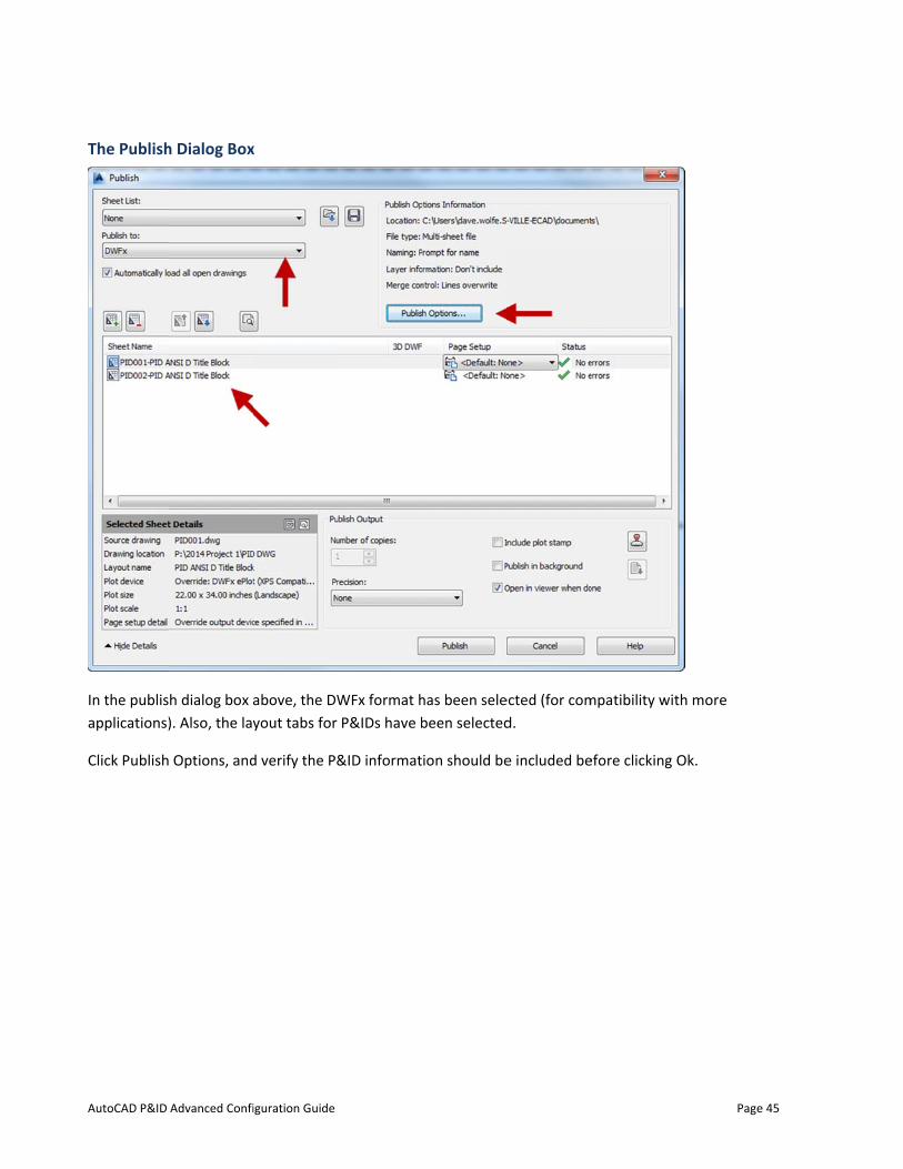
The Publish
In the publisapplications)
Click Publish
Advanced Confi
h Dialog Box
h dialog box a). Also, the lay
Options, and
iguration Guide
x
above, the DWyout tabs for
d verify the P&
WFx format hP&IDs have b
&ID informat
has been selebeen selected
ion should be
ected (for comd.
e included be
mpatibility wit
efore clicking
Page
th more
Ok.
e 45
AutoCAD P&ID
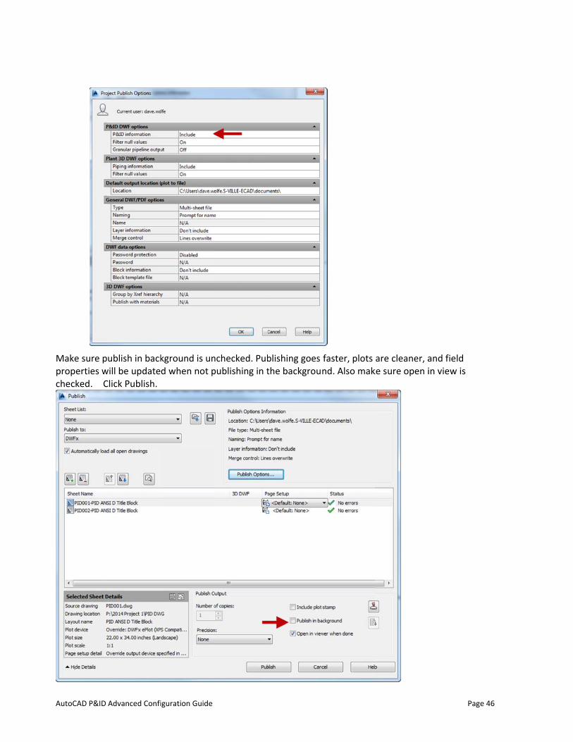
Make sure pproperties wchecked. C
Advanced Confi
ublish in backwill be updateClick Publish.
iguration Guide
kground is und when not p
nchecked. Pubpublishing in t
blishing goes the backgrou
faster, plots nd. Also mak
are cleaner, ake sure open i
Page
and field in view is
e 46
AutoCAD P&ID
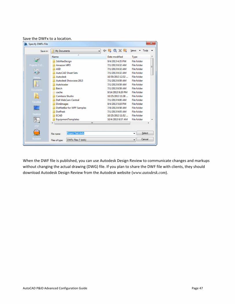
Save the DW
When the DWwithout chandownload Au
Advanced Confi
WFx to a locati
WF file is pubnging the actuutodesk Desig
iguration Guide
ion.
blished, you cual drawing (gn Review fro
an use AutodDWG) file. If y
om the Autod
desk Design Ryou plan to s
desk website (
eview to comhare the DW(www.autode
mmunicate chF file with clie
esk.com).
Page
hanges and ments, they sho
e 47
arkups ould
AutoCAD P&ID
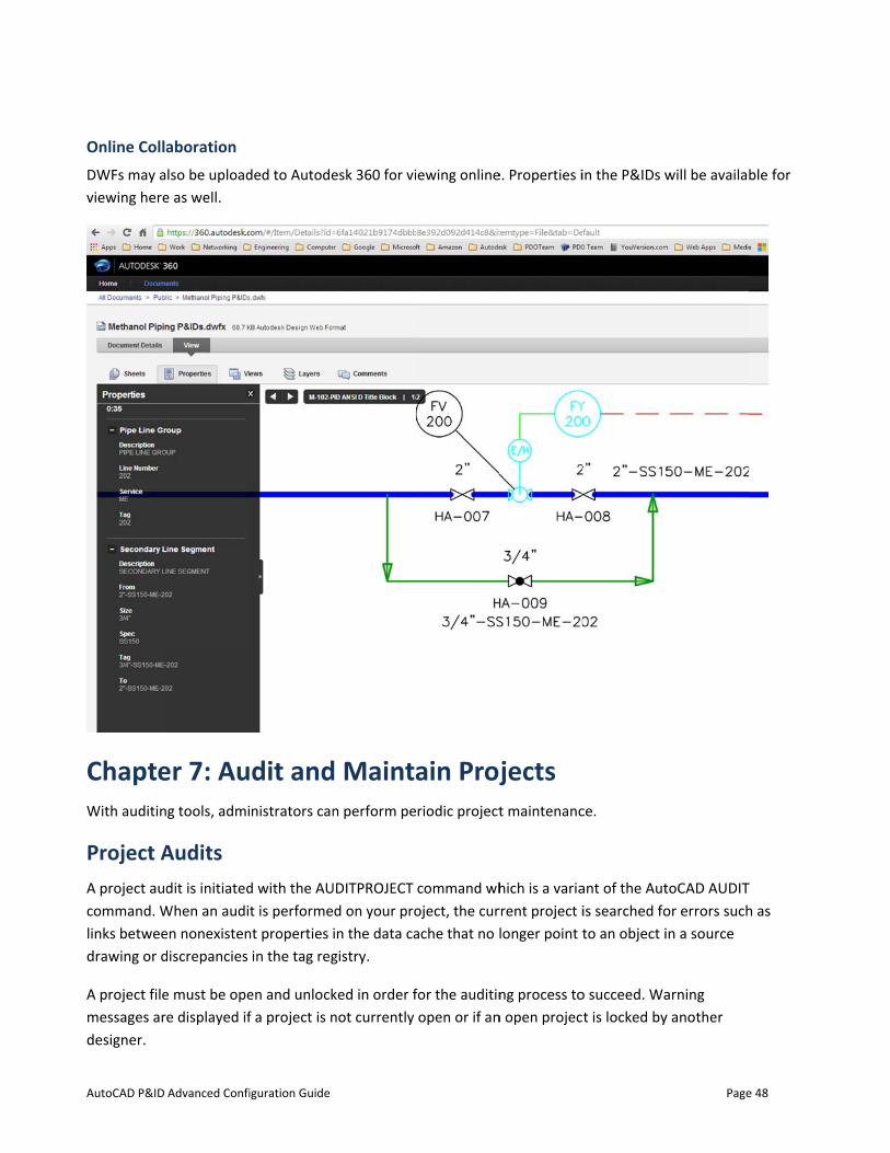
Online CollaDWFs may aviewing here
ChapteWith auditin
Project AA project audcommand. Wlinks betweedrawing or d
A project filemessages ardesigner.
Advanced Confi
aboration lso be upload
e as well.
er 7: Aug tools, admi
Audits dit is initiated
When an audien nonexistendiscrepancies
e must be opee displayed if
iguration Guide
ded to Autode
dit andnistrators can
d with the AUt is performe
nt properties in the tag reg
en and unlockf a project is n
esk 360 for vi
d Maintan perform pe
UDITPROJECT d on your proin the data cagistry.
ked in order fnot currently
ewing online
ain Projriodic project
command whoject, the curache that no l
for the auditinopen or if an
e. Properties i
jects t maintenanc
hich is a variarrent project ilonger point t
ng process ton open projec
in the P&IDs w
ce.
ant of the Autis searched foto an object i
o succeed. Wat is locked by
Page
will be availab
toCAD AUDITor errors suchin a source
arning y another
e 48
ble for
T h as
AutoCAD P&ID
A log file desdirectory con
Project CThe COMPREupdated as wcausing the cdefragment process repa
The project ycompression
Procedu
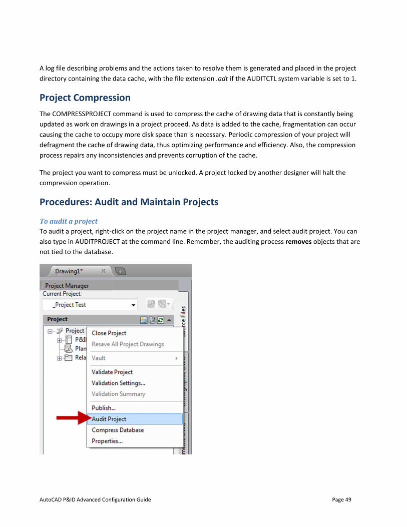
To audit a pTo audit a pralso type in Anot tied to th
Advanced Confi
scribing problntaining the d
CompressESSPROJECT cwork on drawcache to occuthe cache of
airs any incon
you want to cn operation.
res: Audi
project roject, right-cAUDITPROJEChe database.
iguration Guide
ems and the data cache, w
sion command is u
wings in a projupy more diskdrawing datasistencies an
compress mu
it and Ma
click on the prCT at the com
actions takenwith the file ex
used to compject proceed. k space than ia, thus optimid prevents co
st be unlocke
aintain Pr
roject name immand line. R
n to resolve txtension .adt
press the cachAs data is ad
is necessary. zing perform
orruption of t
ed. A project l
rojects
n the project emember, th
hem is generif the AUDITC
he of drawingdded to the caPeriodic com
mance and effithe cache.
locked by ano
manager, anhe auditing pr
rated and placCTL system va
g data that is cache, fragmen
mpression of yiciency. Also,
other designe
nd select audirocess remov
Page
ced in the proariable is set
constantly bentation can o
your project wthe compres
er will halt the
t project. Youves objects th
e 49
oject to 1.
eing occur will ssion
e
u can at are
AutoCAD P&ID
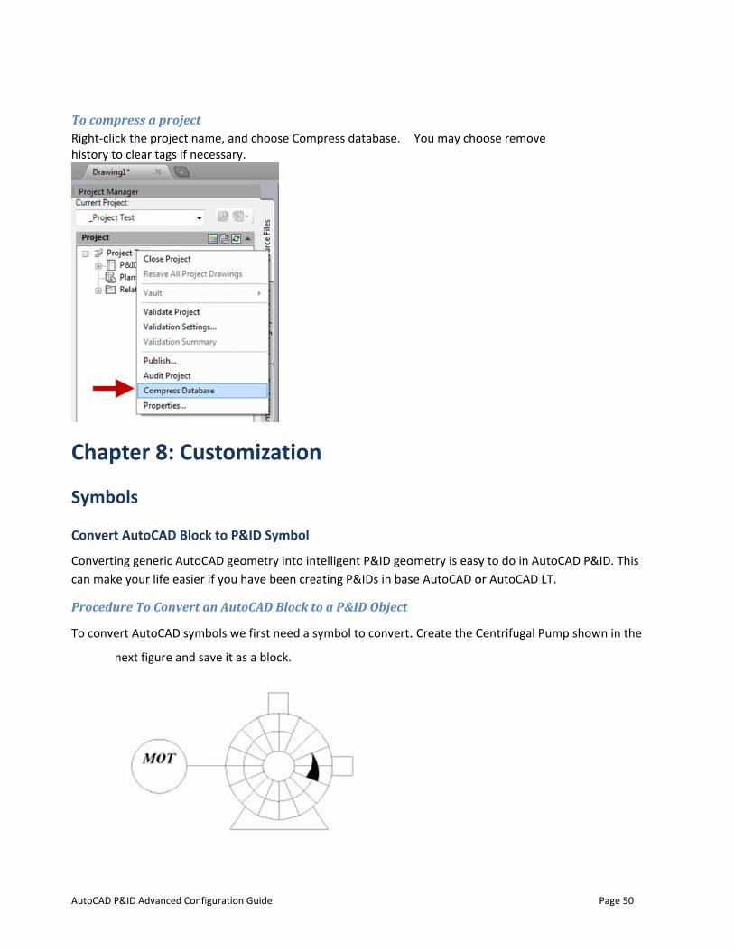
To compresRight-click thhistory to cle
Chapte
Symbols
Convert Au
Converting gcan make yo
Procedure T
To convert A
next
Advanced Confi
ss a project he project namear tags if nec
er 8: Cu
s
toCAD Block
generic AutoCour life easier
To Convert a
AutoCAD sym
t figure and sa
iguration Guide
me, and choocessary.
stomiza
k to P&ID Sy
CAD geometryif you have b
an AutoCAD
bols we first n
ave it as a blo
ose Compress
ation
ymbol
y into intelligebeen creating
Block to a P
need a symbo
ock.
s database.
ent P&ID geoP&IDs in bas
P&ID Object
ol to convert.
You may cho
ometry is easyse AutoCAD o
. Create the C
oose remove
y to do in Autor AutoCAD LT
Centrifugal Pu
Page
toCAD P&ID. TT.
ump shown in
e 50
This
n the
AutoCAD P&ID
When th
This is necesEquipment,
After you coparameters,
This is a one-project proce
Adding aOften you wprevious pro
Advanced Confi
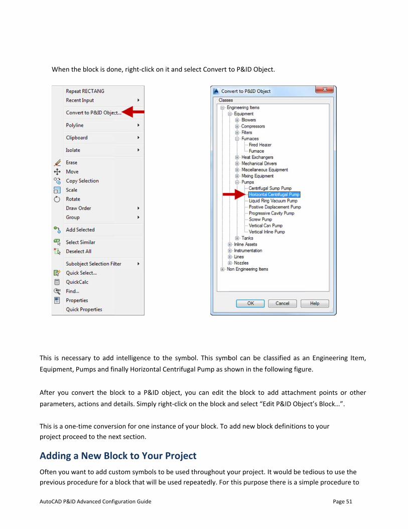
he block is do
ssary to add Pumps and fi
onvert the blactions and d
-time converseed to the ne
a New Bloant to add cu
ocedure for a
iguration Guide
ne, right-click
intelligence nally Horizon
lock to a P&details. Simpl
sion for one iext section.
ock to Youstom symbol
block that wi
k on it and se
to the symbntal Centrifuga
ID object, yoy right-click o
nstance of yo
our Projecls to be used ill be used rep
lect Convert t
ol. This symbal Pump as sh
ou can edit ton the block a
our block. To
ct throughout ypeatedly. For
to P&ID Obje
bol can be clhown in the f
he block to and select “Ed
add new bloc
your project. r this purpose
ect.
lassified as aollowing figu
add attachmdit P&ID Obje
ck definitions
It would be te there is a sim
Page
an Engineerinre.
ment points oect’s Block…”
s to your
edious to usemple procedu
e 51
ng Item,
or other .
e the ure to
AutoCAD P&ID
add custom
This proceduthe block yo
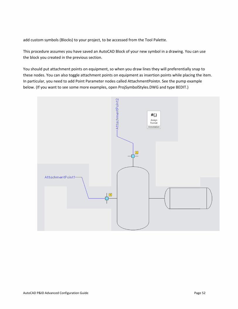
You should pthese nodesIn particular,below. (If yo
Advanced Confi
symbols (Bloc
ure assumes yu created in t
put attachme. You can also, you need tou want to see
iguration Guide
cks) to your p
you have savethe previous s
nt points on eo toggle attac add Point Pae some more
project, to be
ed an AutoCAsection.
equipment, schment pointsarameter nod
examples, op
accessed fro
AD Block of yo
o when you ds on equipme
des called Attapen ProjSymb
m the Tool P
our new symb
draw lines theent as insertioachmentPoinbolStyles.DW
alette.
bol in a drawi
ey will preferon points whi
ntn. See the pG and type B
Page
ing. You can u
rentially snap ile placing theump exampleEDIT.)
e 52
use
to e item. e
AutoCAD P&ID
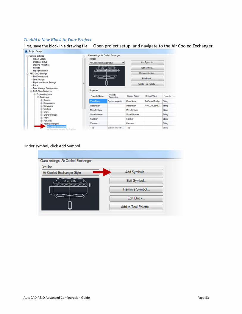
To Add a NeFirst, save th
Under symbo
Advanced Confi
ew Block to Yhe block in a d
ol, click Add S
iguration Guide
Your Projectdrawing file.
Symbol.
t Open projeect setup, annd navigate to the Air Co
Page
ooled Excha
e 53
nger.
AutoCAD P&ID
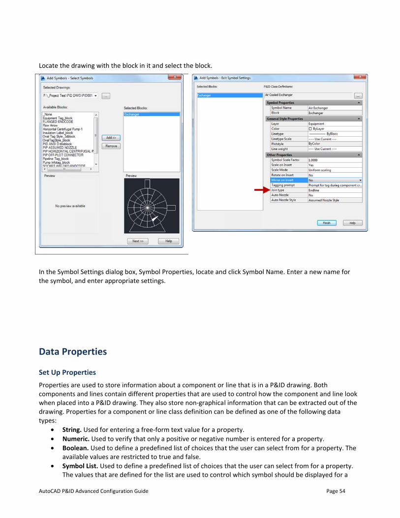
Locate the d
In the Symbothe symbol,
Data Pro
Set Up PropProperties arcomponentswhen placeddrawing. Protypes:
• Strin• Num• Bool
avail• Sym
The
Advanced Confi
rawing with t
ol Settings diaand enter ap
operties
perties re used to sto
s and lines cond into a P&ID operties for a
ng. Used for emeric. Used tolean. Used tolable values abol List. Usedvalues that a
iguration Guide
the block in it
alog box, Sympropriate set
ore informationtain differendrawing. Thecomponent o
entering a freo verify that oo define a preare restricted d to define a re defined fo
t and select th
mbol Propertietings.
on about a cont properties ey also store nor line class d
e-form text vonly a positivedefined list oto true and f
predefined lisr the list are u
he block.
es, locate and
omponent or that are used
non-graphicaldefinition can
value for a proe or negative
of choices thafalse. st of choices tused to contr
d click Symbo
line that is ind to control hl informationbe defined a
operty. number is ent the user can
that the userrol which sym
ol Name. Ente
n a P&ID drawow the comp that can be e
as one of the f
ntered for a pn select from
r can select frmbol should b
Page
er a new name
wing. Both ponent and linextracted outfollowing dat
property. for a propert
om for a prope displayed f
e 54
e for
ne look t of the ta
ty. The
perty. or a
AutoCAD P&ID
com• Sele
The can e
• Acqupropprop
While AutoConly the procomplexity in
Procedures
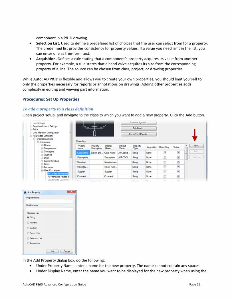
To add a prOpen project
In the Add P• Und• Und
Advanced Confi
ponent in a Pction List. Uspredefined lienter one as uisition. Definperty. For exaperty of a line
CAD P&ID is flperties necesn editing and
s: Set Up Pro
roperty to a ct setup, and n
roperty dialoer Property Ner Display Na
iguration Guide
P&ID drawinged to define st provides cofree-form texnes a rule stample, a rule s
e. The source
exible and allssary for repo viewing part
operties
class definitnavigate to th
g box, do the
Name, enter aame, enter th
. a predefined onsistency foxt. ting that a costates that a can be chose
lows you to corts or annotat information.
tion e class to wh
e following: a name for the name you w
list of choicer property va
omponent’s phand valve ac
en from class,
reate your owations on draw.
ich you want
e new propewant to be dis
es that the usealues. If a valu
property acqucquires its siz project, or d
wn propertieswings. Adding
to add a new
rty. The namesplayed for th
er can select ue you need i
uires its valueze from the codrawing prope
s, you shouldg other prope
w property. Cl
e cannot conhe new prope
Page
from for a prsn’t in the list
from anotheorrespondingerties.
d limit yourselerties adds
ick the Add b
tain any spacerty when usi
e 55
roperty. t, you
er g
lf to
utton.
ces. ing the
AutoCAD P&ID
Data• Und
Click OK.
If yocrea
If yosour
Click OK.
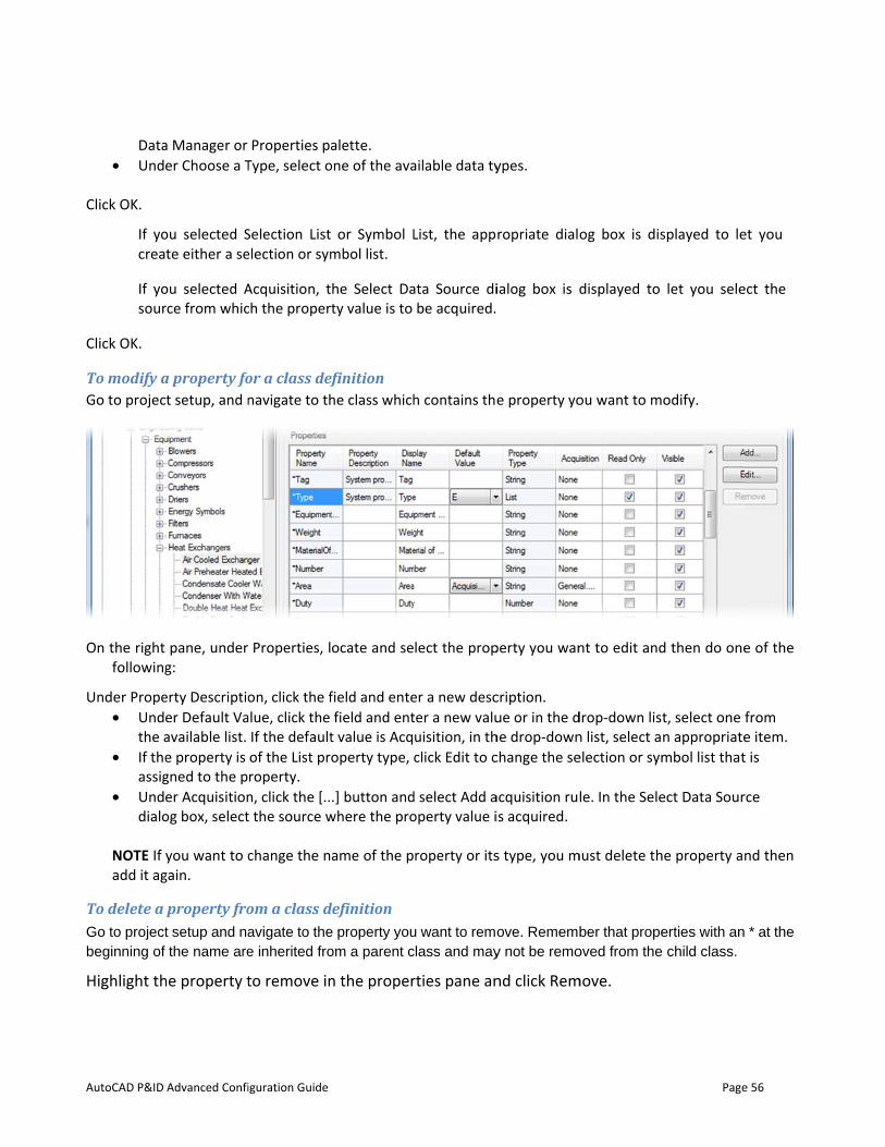
To modify aGo to projec
On the right following
Under Prope• Und
the a• If the
assig• Und
dialo
NOTE If add it ag
To delete a Go to projectbeginning of
Highlight th
Advanced Confi
a Manager or er Choose a T
ou selected Ste either a se
ou selected Arce from whic
a property fot setup, and n
pane, under g:
erty Descriptioer Default Vaavailable list. e property is gned to the per Acquisitionog box, select
you want to cgain.
property frot setup and nathe name are
he property t
iguration Guide
Properties paType, select o
Selection Listelection or sym
Acquisition, tch the proper
or a class defnavigate to th
Properties, l
on, click the falue, click the
If the defaultof the List prroperty. n, click the [..t the source w
change the n
om a class davigate to thee inherited fro
to remove in
alette. one of the ava
or Symbol Lmbol list.
he Select Daty value is to
efinition he class which
ocate and se
field and entefield and ent
t value is Acqoperty type,
.] button andwhere the pro
ame of the p
definition e property youom a parent c
n the proper
ailable data ty
List, the app
ata Source dibe acquired.
h contains the
lect the prop
er a new descter a new valuuisition, in thclick Edit to c
d select Add aoperty value i
roperty or its
u want to remoclass and may
rties pane an
ypes.
ropriate dial
ialog box is d
e property yo
perty you wan
cription. ue or in the dhe drop-downchange the se
acquisition ruis acquired.
s type, you m
ove. Rememby not be remo
nd click Rem
og box is dis
displayed to
ou want to m
nt to edit and
drop-down listn list, select aelection or sym
le. In the Sele
must delete th
ber that propeoved from the
move.
Page
splayed to le
let you sele
odify.
d then do one
t, select one fn appropriatembol list that
ect Data Sour
he property an
erties with an child class.
e 56
et you
ect the
e of the
from e item. t is
rce
nd then
* at the
AutoCAD P&ID
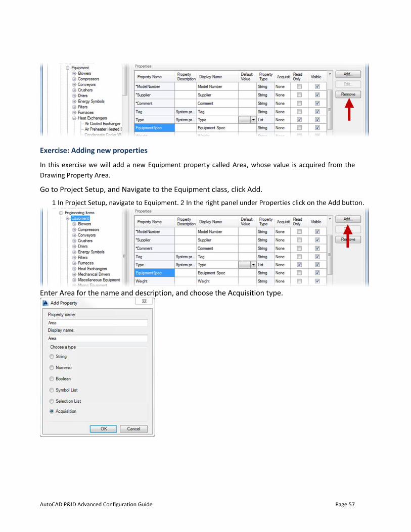
Exercise: Ad
In this exercDrawing Pro
Go to Proje
1 In Proj
Enter Area f
Advanced Confi
dding new p
cise we will aperty Area.
ct Setup, an
ect Setup, na
for the nam
iguration Guide
properties
add a new Eq
d Navigate t
avigate to Equ
e and descri
quipment pro
to the Equip
uipment. 2 In
iption, and c
operty called
ment class,
the right pan
choose the A
Area, whose
click Add.
nel under Pro
Acquisition ty
e value is acq
operties click o
ype.
Page
quired from t
on the Add b
e 57
the
utton.
AutoCAD P&ID
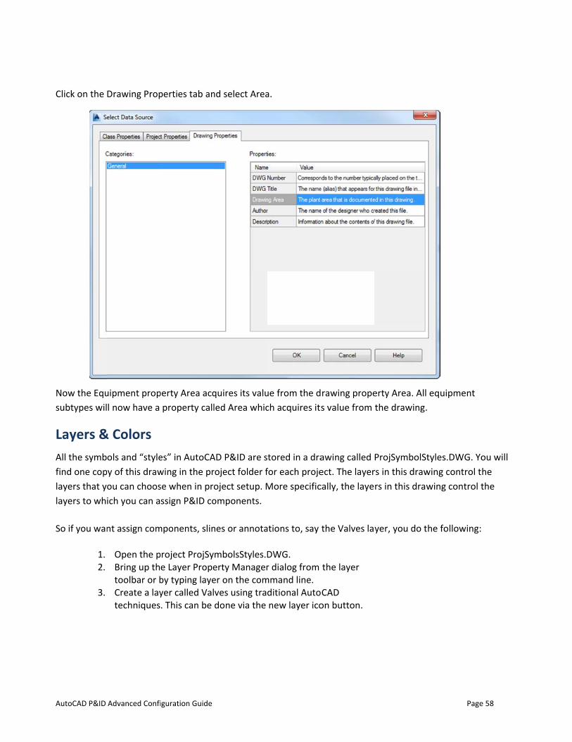
Click on the
Now the Equsubtypes wil
Layers &All the symbfind one coplayers that ylayers to wh
So if you wan
1. 2.
3.
Advanced Confi
Drawing Prop
uipment propl now have a
& Colors ols and “style
py of this drawou can choosich you can a
nt assign com
Open the pBring up thtoolbar or bCreate a laytechniques
iguration Guide
perties tab an
perty Area acqproperty call
es” in AutoCAwing in the prse when in prossign P&ID co
mponents, slin
project ProjSye Layer Propeby typing layeyer called Val. This can be
nd select Area
quires its valuled Area whic
AD P&ID are sroject folder foject setup. Momponents.
nes or annota
mbolsStyles.Derty Managerer on the comves using traddone via the
a.
ue from the dch acquires its
tored in a drafor each projeMore specific
ations to, say
DWG. r dialog from
mmand line. ditional Autonew layer ico
rawing propes value from
awing called ect. The layercally, the laye
the Valves lay
the layer
CAD on button.
erty Area. All the drawing.
ProjSymbolStrs in this drawrs in this draw
yer, you do th
Page
equipment
tyles.DWG. Yowing control twing control t
he following:
e 58
ou will he the

AutoCAD P&ID
You can set thas these saa DWT.
In a real-wornetwork.
Start with th
C:\Users
Plant 3D
1.
2.
3.
4.
Advanced Confi
the layer colome layers, th
rld scenario, y
e user DWT t
s\%USERNAM
D 20XX\RXX.X
Copy it into a
Template.dw
Leave Trainin
projects, you
folder.
Open this DW
Add the Valv
projSymbolS
iguration Guide
ors & linetypehen the syste
you would ma
that was insta
ME%\Local Se
X\enu\ PID AN
a new file wh
wt
ng PID ANSI D
u might want
WT in AutoCA
ves layer, and
tyles.dwg edi
es here – but m will get the
ake the modi
alled with the
ttings\AppDa
NSI D ‐Color D
ich you shoul
D Template.dw
to move you
AD.
set the color
iting (this is d
more often ie DWT layer
fication below
e software:
ata\Local\Aut
Dependent Plo
ld name Train
wt in the sam
r project DWT
r, as shown ab
done from the
t is set in thesettings. We’
w to a templa
todesk\AutoC
ot Styles.dwt
ning PID ANSI
me folder. For
T into the pro
bove, in the
e Layer Prope
e DWT file. As’re also going
ate that is sto
CAD
I D
actual
oject
erties
Page
s long as the Dg to add Valve
ored on your
e 59
DWT es to

AutoCAD P&ID Advanced Configuration Guide Page 60
Manager). S
5. Save and close Training PID ANSI D Template.dwt
HINT: If you are starting your DWT from scratch, design center allows you to drag & drop layers from any DWG/DWT in the tree onto the current drawing. So you could easily drag layers from ProjSymbolStyle.DWG into your DWT.
Speaking of DWT files; AutoCAD P&ID ships with 8 sample DWT files that can be used as a starting point when creating your project’s DWT.
NOTE: Don’t change out of the box files without having a backup/restore plan!
NOTE: If/when making your own DWT, it is highly recommended that you turn wipeout frames off. Otherwise, your instruments and other annotations will look incorrect, and will have boxes around the text. Use the WIPEOUTFRAME system variable to manage the wipeout status.
Any new P&ID drawing will use the DWT specified in Project Setup. The Project Setup dialog has a place in the Paths node to indicate the desired DWT (this is why you can put project specific DWT files in the project folder). Change the Drawing Template here to point to the one we created.
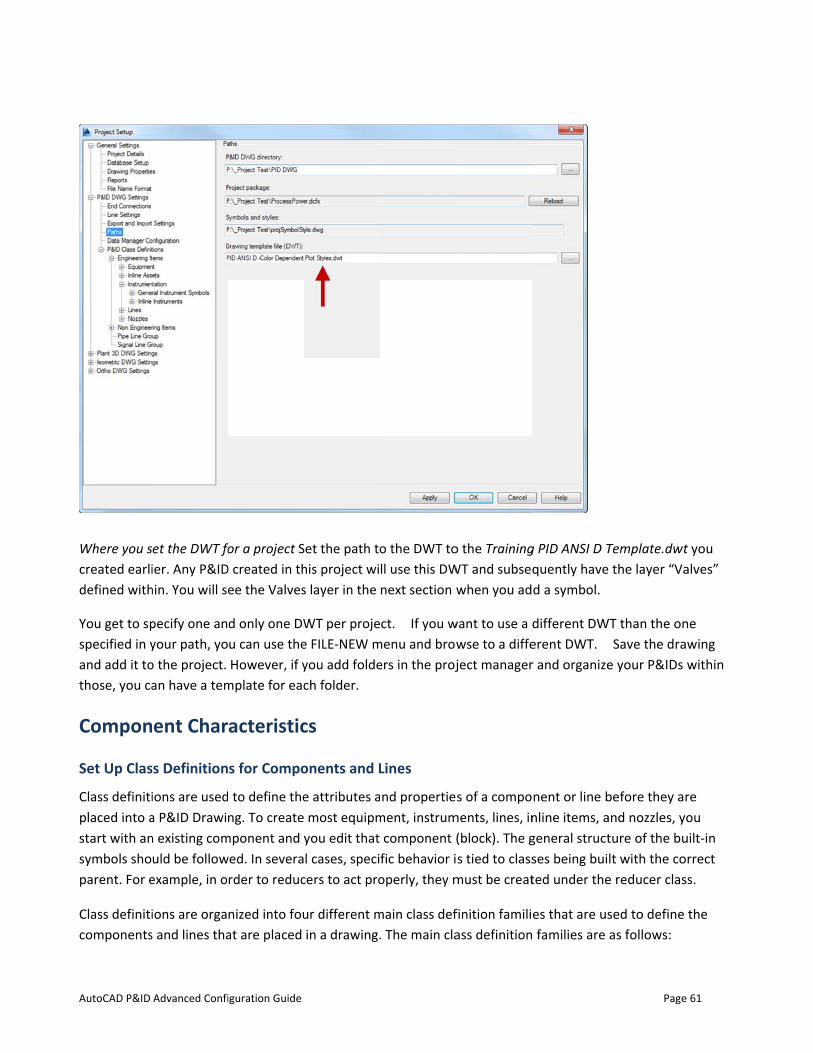
AutoCAD P&ID
Where you screated earlidefined with
You get to spspecified in yand add it tothose, you ca
Compon
Set Up Clas
Class definitiplaced into astart with ansymbols shoparent. For e
Class definiticomponents
Advanced Confi
et the DWT foier. Any P&ID
hin. You will se
pecify one anyour path, yoo the project. an have a tem
ent Char
ss Definition
ions are useda P&ID Drawin existing comuld be follow
example, in o
ions are orgas and lines tha
iguration Guide
or a project SD created in th
ee the Valves
d only one DWu can use theHowever, if y
mplate for eac
acteristic
s for Compo
to define theng. To create
mponent and ywed. In severa
rder to reduc
nized into fouat are placed
Set the path tohis project wis layer in the
WT per projee FILE-NEW myou add foldech folder.
cs
onents and L
e attributes a most equipmyou edit that l cases, speci
cers to act pro
ur different min a drawing.
o the DWT toll use this DWnext section w
ct. If you wmenu and browers in the proj
Lines
nd propertiement, instrum
component (fic behavior ioperly, they m
main class def. The main cla
o the TrainingWT and subseq
when you ad
want to use a dwse to a diffeject manager
s of a compoments, lines, in
(block). The gs tied to class
must be creat
finition familiass definition
g PID ANSI D Tquently haved a symbol.
different DWerent DWT. r and organize
nent or line bnline items, ageneral structses being buited under the
es that are us families are
Page
Template.dwt the layer “Va
WT than the onSave the dra
e your P&IDs
before they aand nozzles, yture of the bult with the co
e reducer clas
sed to defineas follows:
e 61
t you alves”
ne awing
within
re you uilt-in orrect ss.
the
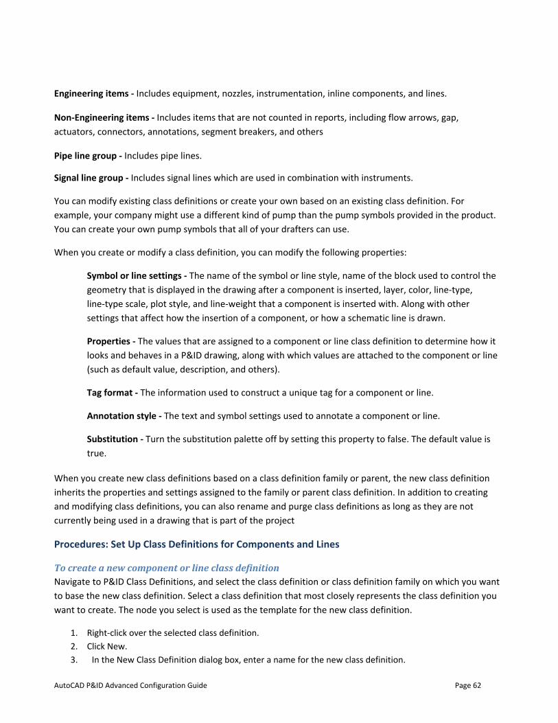
AutoCAD P&ID Advanced Configuration Guide Page 62
Engineering items - Includes equipment, nozzles, instrumentation, inline components, and lines.
Non-Engineering items - Includes items that are not counted in reports, including flow arrows, gap, actuators, connectors, annotations, segment breakers, and others
Pipe line group - Includes pipe lines.
Signal line group - Includes signal lines which are used in combination with instruments.
You can modify existing class definitions or create your own based on an existing class definition. For example, your company might use a different kind of pump than the pump symbols provided in the product. You can create your own pump symbols that all of your drafters can use.
When you create or modify a class definition, you can modify the following properties:
Symbol or line settings - The name of the symbol or line style, name of the block used to control the geometry that is displayed in the drawing after a component is inserted, layer, color, line-type, line-type scale, plot style, and line-weight that a component is inserted with. Along with other settings that affect how the insertion of a component, or how a schematic line is drawn.
Properties - The values that are assigned to a component or line class definition to determine how it looks and behaves in a P&ID drawing, along with which values are attached to the component or line (such as default value, description, and others).
Tag format - The information used to construct a unique tag for a component or line.
Annotation style - The text and symbol settings used to annotate a component or line.
Substitution - Turn the substitution palette off by setting this property to false. The default value is true.
When you create new class definitions based on a class definition family or parent, the new class definition inherits the properties and settings assigned to the family or parent class definition. In addition to creating and modifying class definitions, you can also rename and purge class definitions as long as they are not currently being used in a drawing that is part of the project
Procedures: Set Up Class Definitions for Components and Lines
To create a new component or line class definition Navigate to P&ID Class Definitions, and select the class definition or class definition family on which you want to base the new class definition. Select a class definition that most closely represents the class definition you want to create. The node you select is used as the template for the new class definition.
1. Right-click over the selected class definition. 2. Click New. 3. In the New Class Definition dialog box, enter a name for the new class definition.
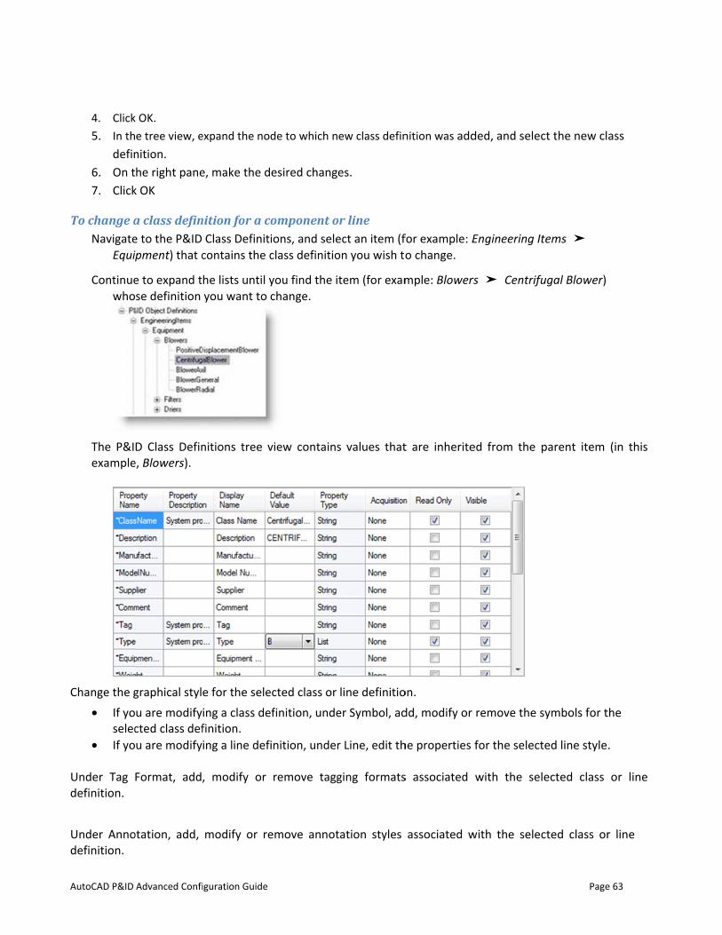
AutoCAD P&ID
4. Click5. In th
defin6. On t7. Click
To change aNavigate
Equi
Continuewho
The P&Iexample
Change the g• If yo
selec• If yo
Under Tag definition.
Under Annodefinition.
Advanced Confi
k OK. e tree view, e
nition. he right pane
k OK
a class define to the P&ID ipment) that c
e to expand tse definition
D Class Define, Blowers).
graphical stylu are modifycted class defu are modify
Format, add,
otation, add,
iguration Guide
expand the no
e, make the d
nition for a cClass Definit
contains the c
he lists until yyou want to
nitions tree v
e for the seleing a class definition. ing a line def
, modify or
modify or re
de to which n
esired chang
component oions, and seleclass definitio
you find the ichange.
view contains
ected class or efinition, unde
inition, under
remove tagg
emove annot
ew class defin
es.
or line ect an item (fon you wish to
tem (for exam
s values that
line definitioer Symbol, ad
r Line, edit th
ging formats
tation styles
nition was add
for example: Eo change.
mple: Blower
t are inherite
on. dd, modify or
he properties
s associated
associated w
ded, and sele
Engineering I
rs ➤ Centrif
ed from the
remove the s
for the select
with the se
with the sele
Page
ct the new cl
Items ➤
fugal Blower)
parent item
symbols for t
ted line style
lected class
cted class or
e 63
ass
(in this
the
.
or line
r line
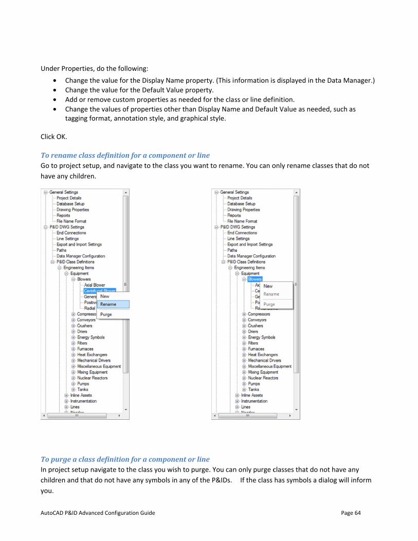
AutoCAD P&ID
Under Prope• Chan• Chan• Add • Chan
tagg Click OK.
To rename Go to projechave any chi
To purge a In project sechildren andyou.
Advanced Confi
erties, do the nge the valuenge the valueor remove cu
nge the valueing format, a
class definitt setup, and nldren.
class definittup navigate that do not h
iguration Guide
following: e for the Disple for the Defaustom properes of propertiennotation sty
tion for a comnavigate to th
tion for a comto the class y
have any sym
lay Name proult Value prorties as needees other thanyle, and graph
mponent or he class you w
mponent or you wish to p
mbols in any o
operty. (This inperty.
ed for the clasn Display Namhical style.
r line want to renam
r line urge. You canf the P&IDs.
nformation is
ss or line defime and Defau
me. You can o
n only purge c If the class
s displayed in
inition. lt Value as ne
only rename c
classes that dhas symbols
Page
n the Data Ma
eeded, such a
classes that d
do not have aa dialog will i
e 64
anager.)
as
do not
ny inform
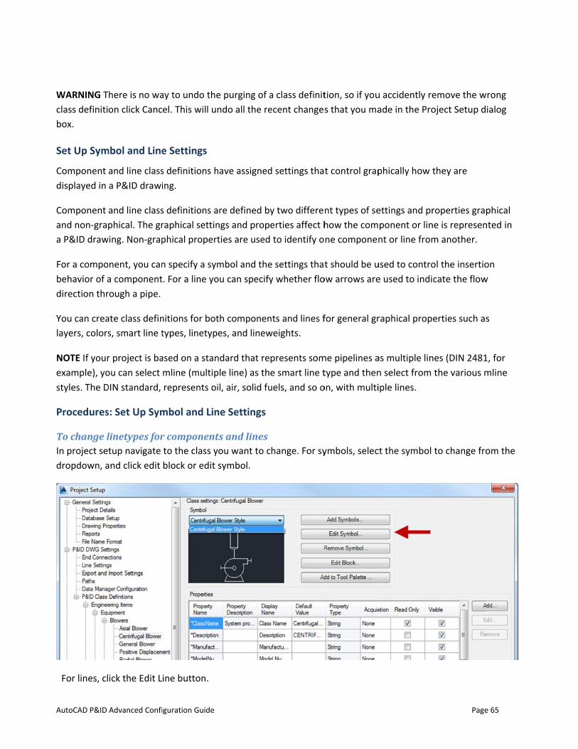
AutoCAD P&ID
WARNING Tclass definitibox.
Set Up Sym
Component displayed in
Component and non-graa P&ID draw
For a compobehavior of adirection thr
You can crealayers, colors
NOTE If yourexample), yostyles. The D
Procedures
To change lIn project sedropdown, a
For lines, cl
Advanced Confi
here is no waon click Canc
mbol and Line
and line classa P&ID drawi
and line classphical. The gr
wing. Non-grap
onent, you cana componentrough a pipe.
ate class defins, smart line t
r project is baou can select DIN standard,
s: Set Up Sym
linetypes fortup navigate
and click edit
ick the Edit L
iguration Guide
ay to undo thel. This will u
e Settings
s definitions hing.
s definitions araphical settinphical proper
n specify a syt. For a line yo
nitions for bottypes, linetyp
ased on a stanmline (multiprepresents o
mbol and Lin
r componentto the class yblock or edit
ine button.
e purging of ando all the re
have assigned
are defined byngs and proprties are used
mbol and theou can specify
th componenpes, and linew
ndard that reple line) as thil, air, solid fu
ne Settings
ts and linesyou want to csymbol.
a class definitecent changes
d settings tha
y two differeerties affect h to identify o
e settings thaty whether flo
nts and lines fweights.
presents some smart line t
uels, and so o
hange. For sy
tion, so if yous that you ma
t control grap
nt types of sehow the comne componen
t should be uow arrows are
for general gr
me pipelines atype and then
on, with multi
ymbols, selec
u accidently reade in the Pro
phically how t
ettings and prponent or linnt or line from
used to controe used to indi
raphical prop
as multiple linn select from iple lines.
ct the symbol
Page
emove the woject Setup d
they are
roperties grapne is represenm another.
ol the insertiocate the flow
erties such as
nes (DIN 2481the various m
to change fro
e 65
rong ialog
phical nted in
on w
s
1, for mline
om the
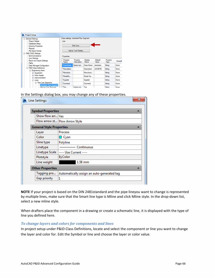
AutoCAD P&ID
In the Setting
NOTE If yourby multiple lselect a new When drafteline you defi
To change lIn project sethe layer and
Advanced Confi
gs dialog box
r project is baines, make su mline style.
ers place the cned here.
layers and ctup under P&d color for. Ed
iguration Guide
, you may cha
ased on the Dure that the S
component in
colors for com&ID Class Defidit the Symbo
ange any of t
DIN 2481standSmart line typ
n a drawing o
mponents annitions, locat
ol or line and
hese propert
dard and the pe is Mline an
or create a sch
nd lines te and select tchoose the la
ties.
pipe lineyou nd click Mline
hematic line,
the componeayer or color
want to chanstyle. In the
it is displayed
ent or line youvalue.
Page
nge is represedrop-down li
d with the typ
u want to cha
e 66
ented st,
pe of
ange
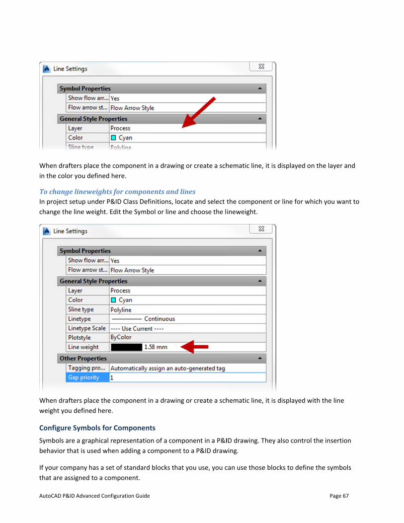
AutoCAD P&ID
When draftein the color y
To change lIn project sechange the l
When drafteweight you d
Configure SSymbols are behavior tha
If your compthat are assig
Advanced Confi
ers place the cyou defined h
lineweights ftup under P&ine weight. E
ers place the cdefined here.
Symbols for a graphical re
at is used whe
pany has a setgned to a com
iguration Guide
component inhere.
for compone&ID Class Defidit the Symbo
component in
Componentepresentationen adding a co
t of standard mponent.
n a drawing o
ents and linnitions, locatol or line and
n a drawing o
ts n of a compoomponent to
blocks that y
or create a sch
es te and select t choose the l
or create a sch
nent in a P&Io a P&ID draw
ou use, you c
hematic line,
the componeineweight.
hematic line,
ID drawing. Twing.
can use those
it is displayed
ent or line for
it is displayed
They also cont
e blocks to de
Page
d on the laye
r which you w
d with the lin
trol the insert
fine the symb
e 67
r and
want to
e
tion
bols
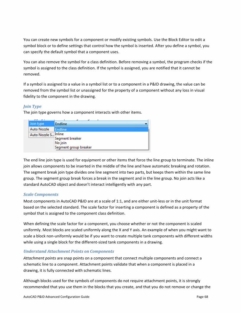
AutoCAD P&ID
You can creasymbol blockcan specify t
You can alsosymbol is assremoved.
If a symbol isremoved frofidelity to th
Join Type The join type
The end line join allows cThe segmentgroup. The sstandard Aut
Scale CompMost compobased on thesymbol that
When definiuniformly. Mscale a blockwhile using a
UnderstandAttachment schematic lindrawing, it is
Although blorecommende
Advanced Confi
ate new symbk or to definehe default sy
remove the signed to the
s assigned to m the symboe component
e governs how
join type is uomponents tt break join tyegment groutoCAD object
ponents onents in Autoe selected stais assigned to
ng the scale fMost blocks ark non-uniforma single block
d Attachmenpoints are sn
ne to a compos fully connec
ocks used for ed that you u
iguration Guide
bols for a come settings thatymbol that a c
symbol for a class definiti
a value in a sol list or unasst in the drawi
w a compone
used for equipo be insertedype divides op break force
t and doesn’t
oCAD P&ID arandard. The sco the compon
factor for a core scaled unif
mly would be for the differ
nt Points on ap points on onent. Attach
cted with sche
the symbols use them in th
mponent or mt control howcomponent u
class definitioon. If the sym
symbol list or signed for theng.
ent interacts w
pment or othd in the middlne line segme
es a break in tinteract intel
re at a scale ocale factor fo
nent class def
omponent, yoformly along tif you want torent-sized tan
Componentsa component
hment points ematic lines.
of componenhe blocks that
odify existingw the symbol i
ses.
on. Before rembol is assign
to a compone property of
with other ite
er items that e of the line aent into two pthe segment alligently with
of 1:1, and arer inserting a c
finition.
ou choose whthe X and Y axo create multnk componen
s t that connecvalidate that
nts do not reqt you create,
g symbols. Usis inserted. Af
moving a symed, you are n
nent in a P&IDa componen
ems.
force the lineand have autparts, but keeand in the linany part.
e either unit-component is
hether or not xis. An examptiple tank comnts in a drawin
ct multiple cot when a com
quire attachmand that you
se the Block Efter you defin
mbol, the prognotified that it
D drawing, thet without any
e group to teomatic breakeps them wit
ne group. No j
-less or in thes defined as a
the componeple of when ymponents witng.
omponents anmponent is pla
ment points, it do not remo
Page
Editor to edit ne a symbol, y
gram checks t cannot be
e value can by loss in visua
rminate. Theking and rotathin the samejoin acts like a
e unit format a property of
ent is scaled you might wath different w
nd connect a aced in a
t is strongly ove or change
e 68
a you
if the
e al
e inline tion.
e line a
the
nt to widths
e the
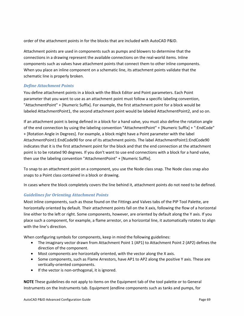
AutoCAD P&ID Advanced Configuration Guide Page 69
order of the attachment points in for the blocks that are included with AutoCAD P&ID.
Attachment points are used in components such as pumps and blowers to determine that the connections in a drawing represent the available connections on the real-world items. Inline components such as valves have attachment points that connect them to other inline components. When you place an inline component on a schematic line, its attachment points validate that the schematic line is properly broken.
Define Attachment Points You define attachment points in a block with the Block Editor and Point parameters. Each Point parameter that you want to use as an attachment point must follow a specific labeling convention, "AttachmentPoint" + [Numeric Suffix]. For example, the first attachment point for a block would be labeled AttachmentPoint1, the second attachment point would be labeled AttachmentPoint2, and so on.
If an attachment point is being defined in a block for a hand valve, you must also define the rotation angle of the end connection by using the labeling convention "AttachmentPoint" + [Numeric Suffix] + ":EndCode" + [Rotation Angle in Degrees]. For example, a block might have a Point parameter with the label AttachmentPoint1:EndCode90 for one of its attachment points. The label AttachmentPoint1:EndCode90 indicates that it is the first attachment point for the block and that the end connection at the attachment point is to be rotated 90 degrees. If you don't want to use end connections with a block for a hand valve, then use the labeling convention "AttachmentPoint" + [Numeric Suffix].
To snap to an attachment point on a component, you use the Node class snap. The Node class snap also snaps to a Point class contained in a block or drawing.
In cases where the block completely covers the line behind it, attachment points do not need to be defined.
Guidelines for Orienting Attachment Points Most inline components, such as those found on the Fittings and Valves tabs of the PIP Tool Palette, are horizontally oriented by default. Their attachment points fall on the X axis, following the flow of a horizontal line either to the left or right. Some components, however, are oriented by default along the Y axis. If you place such a component, for example, a flame arrestor, on a horizontal line, it automatically rotates to align with the line’s direction.
When configuring symbols for components, keep in mind the following guidelines: • The imaginary vector drawn from Attachment Point 1 (AP1) to Attachment Point 2 (AP2) defines the
direction of the component. • Most components are horizontally oriented, with the vector along the X axis. • Some components, such as Flame Arrestors, have AP1 to AP2 along the positive Y axis. These are
vertically-oriented components. • If the vector is non-orthogonal, it is ignored.
NOTE These guidelines do not apply to items on the Equipment tab of the tool palette or to General Instruments on the Instruments tab. Equipment (endline components such as tanks and pumps, for
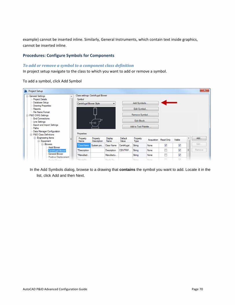
AutoCAD P&ID
example) cancannot be in
Procedures
To add or rIn project se
To add a sym
In the Ad
list, c
Advanced Confi
nnot be inserserted inline.
s: Configure
emove a symtup navigate
mbol, click Ad
dd Symbols d
click Add and
iguration Guide
rted inline. Sim.
Symbols for
mbol to a comto the class t
d Symbol
dialog, browse
d then Next.
milarly, Gene
r Componen
mponent clato which you w
e to a drawing
ral Instrumen
nts
ass definitionwant to add o
g that contain
nts, which co
n or remove a s
ns the symbo
ntain text ins
symbol.
ol you want to
Page
side graphics,
add. Locate
e 70
it in the
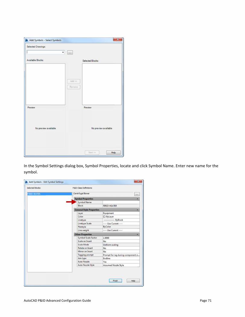
AutoCAD P&ID
In the Symbosymbol.
Advanced Confi
ol Settings dia
iguration Guide
alog box, Symmbol Propertie
es, locate andd click Symbo
ol Name. Ente
Page
er new name f
e 71
for the
AutoCAD P&ID
Fill out t
To remove aNavigate to t
To set the dIn project seGraphicalStyValue columthe compone
Advanced Confi
the rest of th
a symbol forthe class that
default symbtup navigate
yleName unden, in the dropent into a P&
iguration Guide
he properties
r a componet contains the
bol for a comto the class y
er the Properp-down list, sID drawing.
s as is approp
ent class defie symbol, sele
mponent clasyou want to mrty Name coluelect the sym
priate for the
finition ect the symbo
ss definition modify. On thumn. In the
mbol you want
e symbol you
ol from the dr
e right pane, GraphicalStyt to use as th
are Adding.
rop down and
under PropeyleName row,e default sym
Page
d click Remov
erties, locate , under the D
mbol when ins
e 72
ve.
Default serting
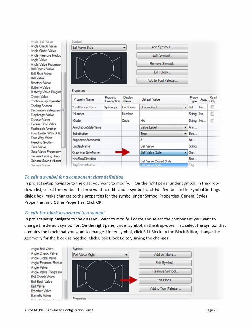
AutoCAD P&ID
To edit a syIn project sedown list, sedialog box, mProperties, a
To edit the In project sechange the dcontains thegeometry fo
Advanced Confi
ymbol for a ctup navigate
elect the symbmake changesand Other Pro
block associtup navigate
default symbo block that yor the block as
iguration Guide
component cto the class y
bol that you ws to the propeoperties. Click
iated to a syto the class y
ol for. On theou want to chs needed. Clic
class definitiyou want to mwant to edit. erties for the k OK.
ymbol you want to m right pane, u
hange. Under ck Close Block
ion modify. On tUnder symbosymbol unde
modify. Locateunder Symbol
symbol, clickk Editor, savin
the right panol, click Edit Ser Symbol Pro
e and select tl, in the drop-k Edit Block. Inng the change
e, under Symymbol. In the
operties, Gen
the compone-down list, sen the Block Edes.
Page
mbol, in the dre Symbol Setteral Styles
ent you want telect the symbditor, change
e 73
rop-tings
to bol that
e the
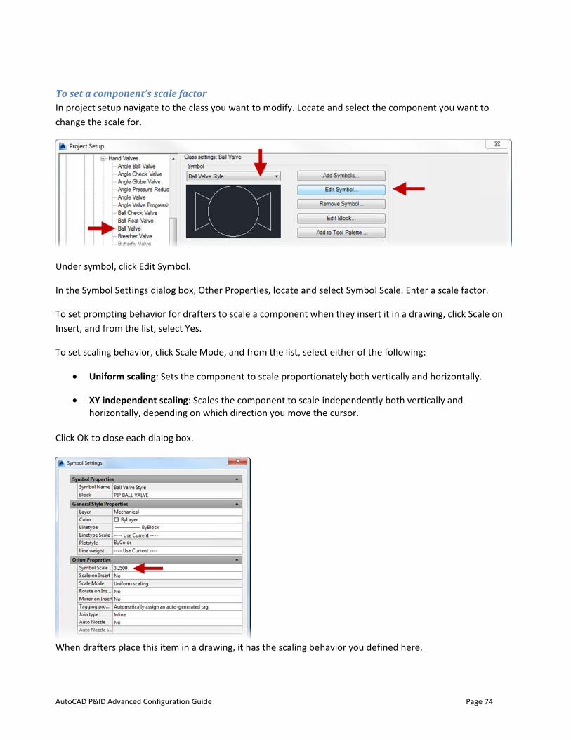
AutoCAD P&ID
To set a comIn project sechange the s
Under symbo
In the Symbo
To set prompInsert, and fr
To set scaling
• Unif
• XY inhoriz
Click OK to c
When drafte
Advanced Confi
mponent’s sctup navigate
scale for.
ol, click Edit S
ol Settings dia
pting behaviorom the list, s
g behavior, c
form scaling:
ndependent szontally, depe
lose each dia
ers place this
iguration Guide
cale factor to the class y
Symbol.
alog box, Oth
or for draftersselect Yes.
lick Scale Mo
Sets the com
scaling: Scaleending on wh
log box.
item in a draw
you want to m
er Properties
s to scale a co
de, and from
mponent to sca
es the componhich direction
wing, it has th
modify. Locate
s, locate and s
omponent wh
the list, selec
ale proportio
nent to scale you move th
he scaling beh
e and select t
select Symbo
hen they inse
ct either of th
onately both v
independenthe cursor.
havior you de
the compone
ol Scale. Enter
rt it in a draw
he following:
vertically and
tly both vertic
efined here.
Page
ent you want t
r a scale facto
wing, click Sca
horizontally.
cally and
e 74
to
or.
ale on
.

AutoCAD P&ID
To add a coNOTE BeforeIn project setool palette.
Click the Add
To create a The followinattachment general stepunless you w
NOTE Beforethat the activare adding a
1. Crea2. Click3. In th4. Mak5. On t
(for 6. Righ7. In th8. Click9. Crea
Advanced Confi
omponent to e you start thtup navigate
d to Tool Pale
componentg procedure points (wher
ps. Not all cowant to define
e you start thve tool palett pump to the
ate a new block Tools menu he Block Editoke sure Midpohe Parameteexample: on t-click the pa
he Properties k anywhere inate another p
iguration Guide
the tool palis procedure,to the class y
ette button.
t with attachillustrates hore schematic mponents re
e them.
is procedure,te tab is the o
e tool palette,
ck (for examp➤ Block Ed
or dialog box, oint snaps arers tab of the the inlet of thrameter. Clicpalette, Prop
n the drawingarameter (for
lette , make sure thyou want to m
hment pointsow you would
lines will snaequire attach
, make sure thone where yo, make sure th
ple: a horizonditor.
click Currente off. Block Authorhe pump). k Properties.
perty Labels, eg, and then prr example: at
he P&ID tool modify. Locate
s and add it create a pumap). You can ment points
he P&ID tool u want to addhe Equipmen
tal centrifuga
t Drawing, an
ing palette, c
enter attachmress ESC on tht the outlet of
palette is dise and select t
to the tool pmp (an endlin
create other(for example
palette is disd the new co
nt tab is active
al pump). Sav
d click OK.
click Point Par
mentpoint1. he keyboard. f the pump),
splayed. the class you
palette ne componenr componente, tanks do n
splayed in youomponent (foe).
ve the drawin
rameter, and
and label it a
Page
want to add
t) and defines using the s
not require th
ur drawing anr example, if
ng file.
place a param
ttachmentpo
e 75
to a
e two same hem)
nd you
meter
oint2.
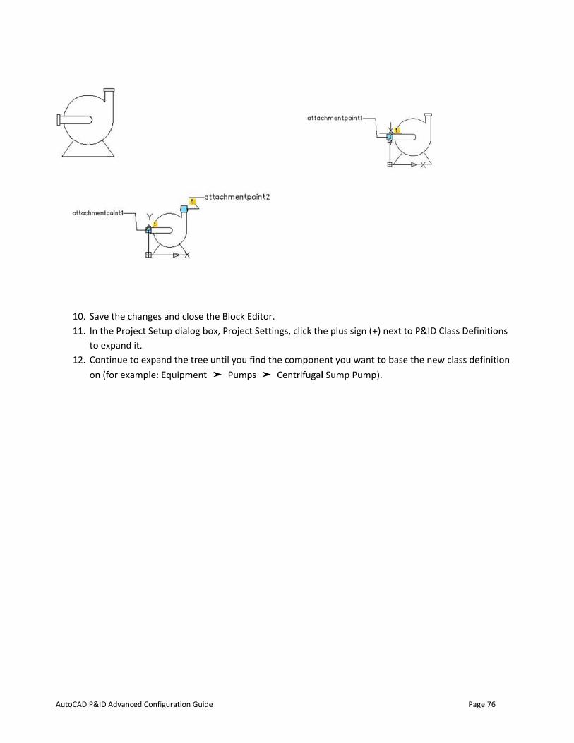
AutoCAD P&ID
10. Save11. In th
to ex12. Cont
on (f
Advanced Confi
e the changeshe Project Setxpand it. tinue to expafor example:
iguration Guide
s and close thtup dialog box
nd the tree uEquipment ➤
e Block Editox, Project Sett
until you find t➤ Pumps ➤
r. tings, click th
the compone➤ Centrifugal
he plus sign (+
ent you want l Sump Pump
+) next to P&I
to base the np).
Page
D Class Defin
new class def
e 76
nitions
inition

AutoCAD P&ID Advanced Configuration Guide Page 77
13. Right-click over the selected class definition. Click New.
NOTE Instead of creating a new class definition, you can also add a new symbol to an existing class definition. To add a new symbol to an existing class definition, see To add a symbol to a component definition.
14. In the New Class Definition dialog box, enter a name for the new class definition (for example: horizontal centrifugal pump).
15. Click OK 16. Expand the node that the new class definition was added to, and select the new class definition. 17. On the right pane, under Symbol, click Add Symbol. 18. In the Symbol Settings dialog box, under Symbol Properties, do the following:
a. Next to Symbol Name, enter a name for the symbol that is being added to the new class definition.
b. Next to Block, click the [...] button, and navigate to the drawing you created in step 1. c. Select that drawing and in the Select Block dialog box, select a symbol name (block) from the
list. Click OK. d. (Optional) Make other changes to the settings of the component you just created. e. Click OK.
19. On the right pane, make the desired changes to the new class definition’s properties, tag format, and annotation style.
20. Under Symbol, click Add to Tool Palette. The new class definition is added to the active tool palette. The new tool can be used just like the default tools provided with AutoCAD P&ID, and will be included in reports.
NOTE If the tool palette is not open when you click Create Tool; the component is still added to the bottom of the last-active tool palette.
Configure the Appearance of Lines
You can set up the arrow behavior of lines. You set up whether a flow arrow is displayed when a line is added to a drawing (not all lines need a flow arrow), and the type of flow arrow symbol that is displayed in the drawing, and whether to prompt for the insertion of a flag.
Procedures: Configure the Appearance of Lines
To set up line arrow behavior In project setup navigate to the class you want to modify. Locate and select the line you want to modify.
1. Select the line style you want to modify the line arrow behavior for (for example: Primary). 2. Under Line, click Edit Line. 3. In the Line Settings dialog box, under Symbol Properties, to the right of Flow Arrow Style, select a
symbol from the list. Click OK. 4. Click OK.
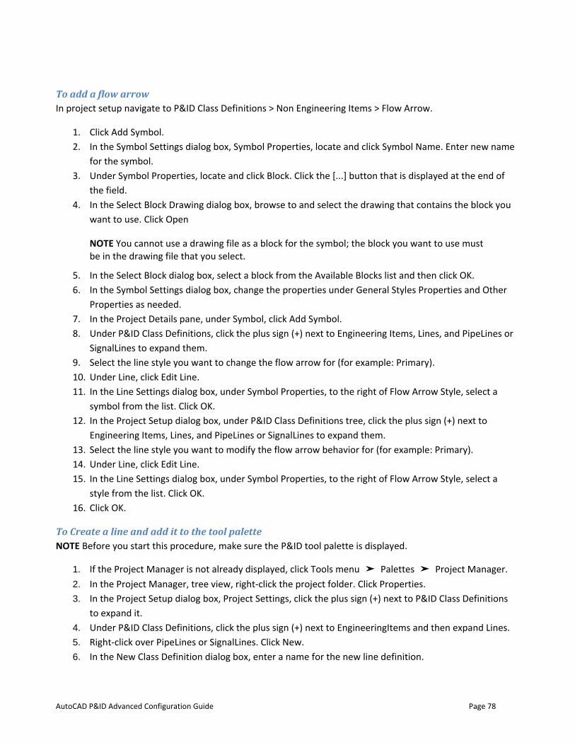
AutoCAD P&ID Advanced Configuration Guide Page 78
To add a flow arrow In project setup navigate to P&ID Class Definitions > Non Engineering Items > Flow Arrow.
1. Click Add Symbol. 2. In the Symbol Settings dialog box, Symbol Properties, locate and click Symbol Name. Enter new name
for the symbol. 3. Under Symbol Properties, locate and click Block. Click the [...] button that is displayed at the end of
the field. 4. In the Select Block Drawing dialog box, browse to and select the drawing that contains the block you
want to use. Click Open
NOTE You cannot use a drawing file as a block for the symbol; the block you want to use must be in the drawing file that you select.
5. In the Select Block dialog box, select a block from the Available Blocks list and then click OK. 6. In the Symbol Settings dialog box, change the properties under General Styles Properties and Other
Properties as needed. 7. In the Project Details pane, under Symbol, click Add Symbol. 8. Under P&ID Class Definitions, click the plus sign (+) next to Engineering Items, Lines, and PipeLines or
SignalLines to expand them. 9. Select the line style you want to change the flow arrow for (for example: Primary). 10. Under Line, click Edit Line. 11. In the Line Settings dialog box, under Symbol Properties, to the right of Flow Arrow Style, select a
symbol from the list. Click OK. 12. In the Project Setup dialog box, under P&ID Class Definitions tree, click the plus sign (+) next to
Engineering Items, Lines, and PipeLines or SignalLines to expand them. 13. Select the line style you want to modify the flow arrow behavior for (for example: Primary). 14. Under Line, click Edit Line. 15. In the Line Settings dialog box, under Symbol Properties, to the right of Flow Arrow Style, select a
style from the list. Click OK. 16. Click OK.
To Create a line and add it to the tool palette NOTE Before you start this procedure, make sure the P&ID tool palette is displayed.
1. If the Project Manager is not already displayed, click Tools menu ➤ Palettes ➤ Project Manager. 2. In the Project Manager, tree view, right-click the project folder. Click Properties. 3. In the Project Setup dialog box, Project Settings, click the plus sign (+) next to P&ID Class Definitions
to expand it. 4. Under P&ID Class Definitions, click the plus sign (+) next to EngineeringItems and then expand Lines. 5. Right-click over PipeLines or SignalLines. Click New. 6. In the New Class Definition dialog box, enter a name for the new line definition.
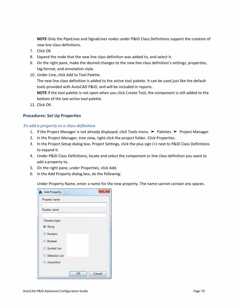
AutoCAD P&ID
NOTnew
7. Click8. Expa9. On t
tag f10. Und
The toolsNOTbott
11. Click
Procedures
To add a pr1. If the2. In th3. In th
to ex4. Und
add 5. On t6. In th
Und
Advanced Confi
TE Only the Pi line class def
k OK and the node he right pane
format, and aer Line, click Anew line class provided wi
TE If the tool pom of the las
k OK.
s: Set Up Pro
roperty to a ce Project Man
he Project Mahe Project Setxpand it. er P&ID Classa property tohe right pane
he Add Proper
er Property N
iguration Guide
peLines and Sfinitions.
that the newe, make the dnnotation styAdd to Tool Ps definition isith AutoCAD Ppalette is not st-active tool
operties
class definitnager is not a
anager, tree vtup dialog box
s Definitions, o. e, under Proprty dialog box
Name, enter a
SignalLines no
w line class deesired chang
yle. Palette. s added to theP&ID, and wiopen when ypalette.
tion already displaview, right-clicx, Project Sett
locate and se
perties, click Ax, do the follo
a name for th
odes under P
efinition was aes to the new
e active tool ll be includedyou click Crea
ayed, click Toock the projecttings, click th
elect the com
Add. owing:
e new prope
P&ID Class De
added to, andw line class de
palette. It cand in reports. ate Tool, the c
ols menu ➤t folder. Click
he plus sign (+
mponent or lin
rty. The name
finitions supp
d select it. efinition’s set
n be used jus
component is
Palettes ➤k Properties. +) next to P&I
ne class defini
e cannot con
Page
port the creat
ttings, proper
t like the defa
s still added t
Project Man D Class Defin
ition you wan
tain any spac
e 79
tion of
rties,
ault
to the
nager.
nitions
nt to
ces.
AutoCAD P&ID Advanced Configuration Guide Page 80
• Below Display Name, enter the name you want to be displayed for the new property when using
the Data Manager or Properties palette. • Under Choose a Type, select one of the available data types.
7. Click OK. If you selected Selection List or Symbol List, the appropriate dialog box is displayed to let
you create either a selection or symbol list. If you selected Acquisition, the Select Data Source dialog box is displayed to let you select the source from which the property value is to be acquired.
8. Click OK.
To modify a property for a class definition 1. 1 If the Project Manager is not already displayed, click Tools menu ➤ Palettes ➤ Project Manager. 2. 2 In the Project Manager, tree view, right-click the project folder. Click Properties. 3. 3 In the Project Setup dialog box, Project Settings, click the plus sign (+) next to P&ID Class
Definitions to expand it. 4. 4 Under P&ID Class Definitions, locate and select the component or line class definition you want to
edit a property for. 5. 5 On the right pane, under Properties, locate and select the property you want to edit and then do
one of the following: • Under Property Description, click the field and enter a new description. • Under Default Value, click the field and enter a new value or in the drop-down list, select one from
the available list. If the default value is Acquisition, in the drop-down list, select an appropriate item. • If the property is of the List property type, click Edit to change the selection or symbol list that is
assigned to the property. • Under Acquisition, click the [...] button and select Add acquisition rule. In the Select Data Source
dialog box, select the source where the property value is acquired.
NOTE If you want to change the name of the property or its type, delete the property and then add it again.
6. Click OK.
To delete a property from a class definition 1. If the Project Manager is not already displayed, click Tools menu ➤ Palettes ➤ Project Manager. 2. In the Project Manager, tree view, right-click the project folder. Click Properties. 3. In the Project Setup dialog box, Project Settings, click the plus sign (+) next to P&ID Class Definitions
to expand it. 4. Under P&ID Class Definitions, locate and select the component or line class definition you want to
edit a property for. 5. On the right pane, under Properties, locate and select the property you want to delete. Click
Remove.

AutoCAD P&ID Advanced Configuration Guide Page 81
6. In the Confirm Delete message box, click Yes. 7. Click OK.
Set Up Property Acquisition When you select acquisition as a property type, you set up a rule stating that the property acquires its value from another property. The acquisition source can be another class, project, or drawing property.
AutoCAD P&ID Advanced Configuration Guide Page 82
Acquisition ensures consistency among component property values. If the source value changes, all components set to acquire that value change as well.
Property acquisition is also useful for maintaining consistent tagging. When you change a source value, tag formats that are based on acquired properties update automatically throughout the project.
Understand Property Acquisition Rules You can select any drawing or project property without restriction as the source of an acquisition rule. When you select a class property as the source, however, make sure that the acquiring class and the source class are connected.
A valve may acquire a size value from a line, for example, because the two are connected in a relationship. A tank and a furnace, however, have no direct link and no one-to-one relationship between them. Therefore, you cannot set up an acquisition rule between them.
You can set up property acquisition rules when the following one-to-one component relationships exist:
• Line and inline asset • Line and start asset • Line and end asset • Line and arrow • Annotated and annotation • Line and break • Line and page connector • Line and nozzle • Pipe line group and pipe line • Signal line group and signal line • Connector and connector • Asset and non-engineering (only between a control valve and its actuator) The following properties have acquisition rules set by default; you can view them when you create a new project:
Acquisition Property Source Property HandValves.Size PipeLines.Size HandValves.Spec PipeLines.Spec InLineInstruments.Size PipeLines.Size PipingSpecialtyItems.Size PipeLines.Size PipingSpecialtyItems.Spec PipeLines.Spec PipingFittings.Size PipeLines.Size PipeFittings.Spec PipeLines.Spec
Understand Acquire Mode and Override Mode A property that is set to acquire its value from another property is in Acquire mode. However, you can switch this property into Override mode and edit the value manually. Once a property is in Override mode,
AutoCAD P&ID
its value is n
The icon nexappear in theis visible, the
• T
• T
UnderstandYou select AcAlternately, component i
After initializvalue manua
Copy or MovWhen you seacquiring froproperty valspecific value
UnderstandMany Acquisone relations
However, a cidentical valuconflicting va
For examplecases, as lonin combinatia question m
UnderstandBy associatinthat pipe line
Although a passociated wavailable:
Advanced Confi
o longer acqu
xt to the prope Properties Pe value is edit
The property
The property
d Initializaticquiring (the you can selecis first initializ
zation, the prally because it
ve Componeet up a compoom the line sizue from the ne accompanie
d Acquisitionsition relationship with a pi
component cues along witalues is the ac
, a three-wayg as the diffeon with blank
mark is display
d Acquisitionng a signal line group’s pro
pipe line grouwith only one
iguration Guide
uired from an
perty indicatePalette, the Dtable.
is in Acquire
is in Override
ion Only default) to se
ct Initializatiozed.
operty movet is no longer
ents with Acqonent properze) and then new line. Howes the valve.
n from Multinships are simipe line and a
an have multh others thatcquisition im
y valve has a derent sources k values, the yed in the val
n Between Sie group with
operties. You m
p can be assopipe line grou
nother source
s whether theData Manager
mode.
e mode
et up a propen Only, which
s immediatel acquired fro
quired Proprty to acquirecopy or move
wever, if the v
iple Sources mple one-to-oacquires its siz
tiple acquisitiot are unspecifpossible. A qu
direct relationeither have tvalve acquireve’s Spec fiel
ignal Line Ga pipe line grmust manual
ociated with mup. Once an a
e.
e property is r, and the Ass
erty to acquireh permits the
y into Overridm another so
erties Betwe its value frome that valve ovalve propert
one relationshze and spec fr
on sources. Iffied, a value cuestion mark
nship with ththe same speces the value. Id.
Groups and Proup, you canly associate t
many signal liassociation is
in Override osign Tag dialo
e its value froe acquisition t
de mode. In Oource.
een Pipelinem another pr
onto another ty you are mo
hips. For examrom that line
f sources havcan be acquirk is displayed
ree different c value (for eIf the pipe lin
Pipe Line Gron set up the sithe groups us
ine groups, a established,
or Acquire moog box. When
om another pto occur only
Override mod
es roperty (for exline, the valv
oving is in ove
mple, a gate ve.
e identical vaed. Only whein place of th
pipe line segexample: PVC)
e segments h
oups ignal line gro
sing SLGROUP
signal line grthe following
Page
ode. The icon the Override
roperty. once, when t
de, you can ed
xample, a vale acquires th
erride mode, t
valve has a on
alues or someen the sourcehe acquired va
gments. In suc) or the same
have different
up to acquirePEDIT.
roup can be g capabilities
e 83
s e icon
the
dit the
ve size e the
ne-to-
e s have alue.
ch e value t specs,
e any of
are
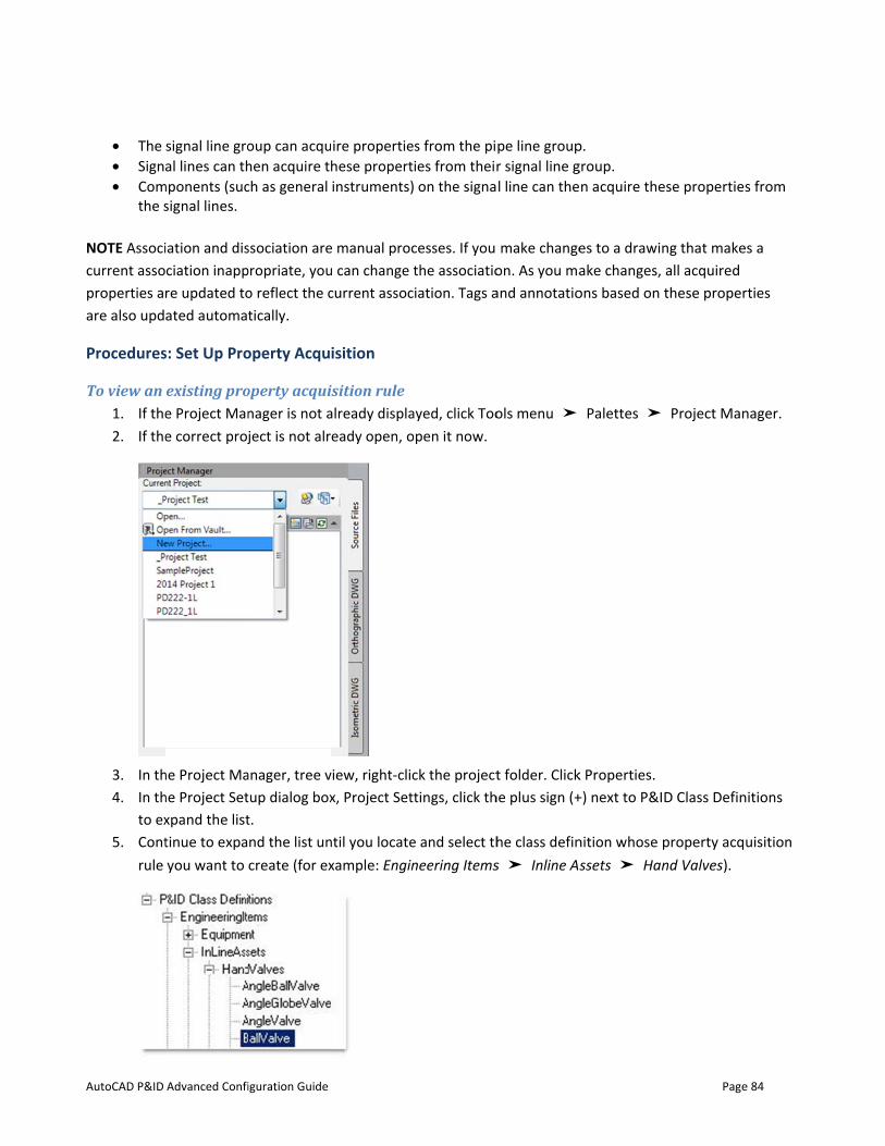
AutoCAD P&ID
• The • Sign• Com
the s NOTE Associcurrent assoproperties aare also upd
Procedures
To view an 1. If the2. If the
3. In th4. In th
to ex5. Cont
rule
Advanced Confi
signal line groal lines can th
mponents (sucsignal lines.
iation and disciation inappre updated toated automat
s: Set Up Pro
existing proe Project Mane correct proj
he Project Mahe Project Setxpand the listtinue to expayou want to
iguration Guide
oup can acquhen acquire thch as general
ssociation arepropriate, youo reflect the ctically.
operty Acqu
operty acquinager is not aject is not alr
anager, tree vtup dialog boxt. nd the list uncreate (for ex
ire propertiehese propertinstruments)
e manual procu can change tcurrent assoc
isition
isition rule already displaeady open, o
view, right-clicx, Project Sett
ntil you locatexample: Engin
s from the piies from their on the signa
cesses. If you the associatioiation. Tags a
ayed, click Toopen it now.
ck the projecttings, click th
e and select thneering Items
pe line groupr signal line gl line can the
make changeon. As you maand annotatio
ols menu ➤
t folder. Clickhe plus sign (+
he class defins ➤ Inline As
p. group.
n acquire the
es to a drawinake changes,
ons based on
Palettes ➤
k Properties. +) next to P&I
nition whose ssets ➤ Han
Page
ese propertie
ng that makeall acquired these proper
Project Man
D Class Defin
property acqnd Valves).
e 84
s from
es a
rties
nager.
nitions
uisition
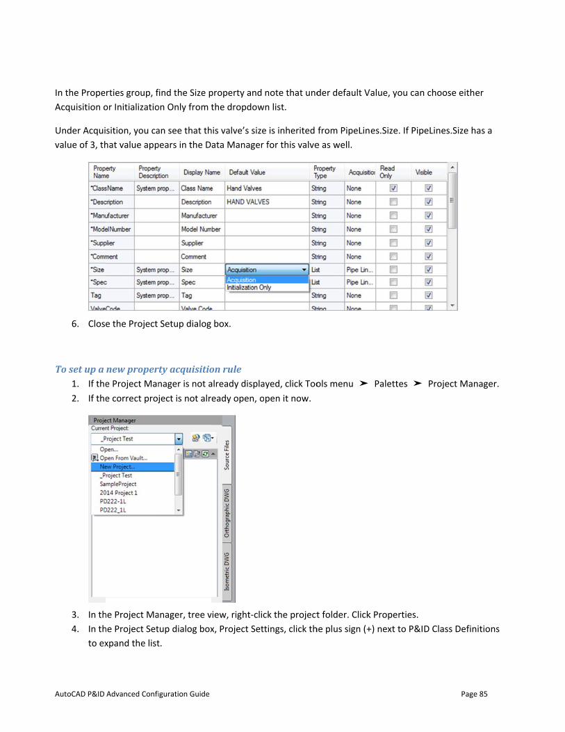
AutoCAD P&ID
In the PropeAcquisition o
Under Acquivalue of 3, th
6. Clos
To set up a 1. If the2. If the
3. In th4. In th
to ex
Advanced Confi
rties group, for Initializatio
sition, you cahat value app
e the Project
new propere Project Mane correct proj
he Project Mahe Project Setxpand the list
iguration Guide
ind the Size pon Only from t
an see that thpears in the D
Setup dialog
rty acquisitionager is not aject is not alr
anager, tree vtup dialog boxt.
property and the dropdow
his valve’s sizeata Manager
box.
on rule already displaeady open, o
view, right-clicx, Project Sett
note that undn list.
e is inherited for this valve
ayed, click Toopen it now.
ck the projecttings, click th
der default V
from PipeLine as well.
ols menu ➤
t folder. Clickhe plus sign (+
Value, you can
es.Size. If Pip
Palettes ➤
k Properties. +) next to P&I
Page
n choose eithe
peLines.Size h
Project Man
D Class Defin
e 85
er
as a
nager.
nitions
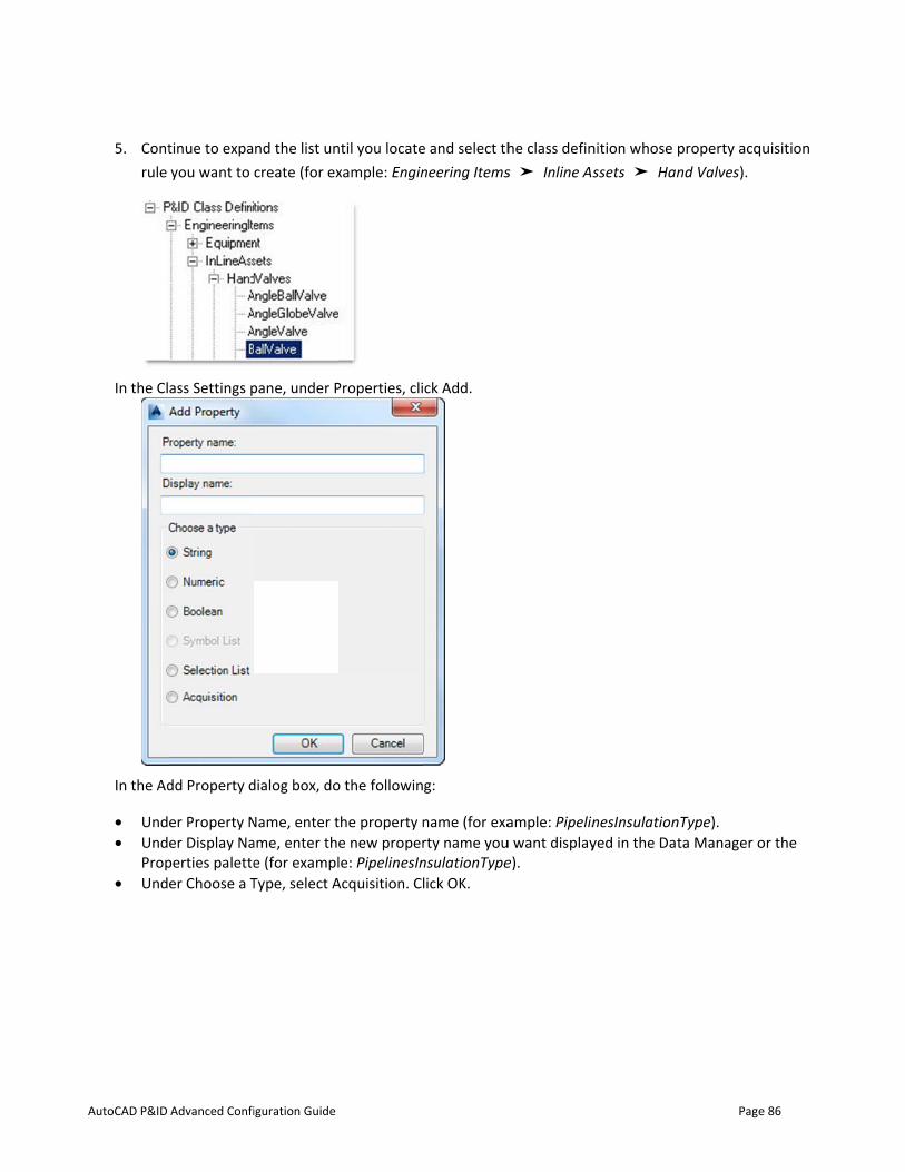
AutoCAD P&ID
5. Contrule
In the Cl
In the Ad
• Und• Und
Prop• Und
Advanced Confi
tinue to expayou want to
ass Settings p
dd Property d
er Property Ner Display Na
perties paletteer Choose a T
iguration Guide
nd the list uncreate (for ex
pane, under P
dialog box, do
Name, enter tame, enter the (for examplType, select A
ntil you locatexample: Engin
Properties, cli
o the followin
the property ne new properle: PipelinesIn
Acquisition. Cl
e and select thneering Items
ck Add.
g:
name (for exarty name younsulationTypelick OK.
he class defins ➤ Inline As
ample: Pipelinu want displaye).
nition whose ssets ➤ Han
nesInsulationyed in the Dat
Page
property acqnd Valves).
nType). ta Manager o
e 86
uisition
or the
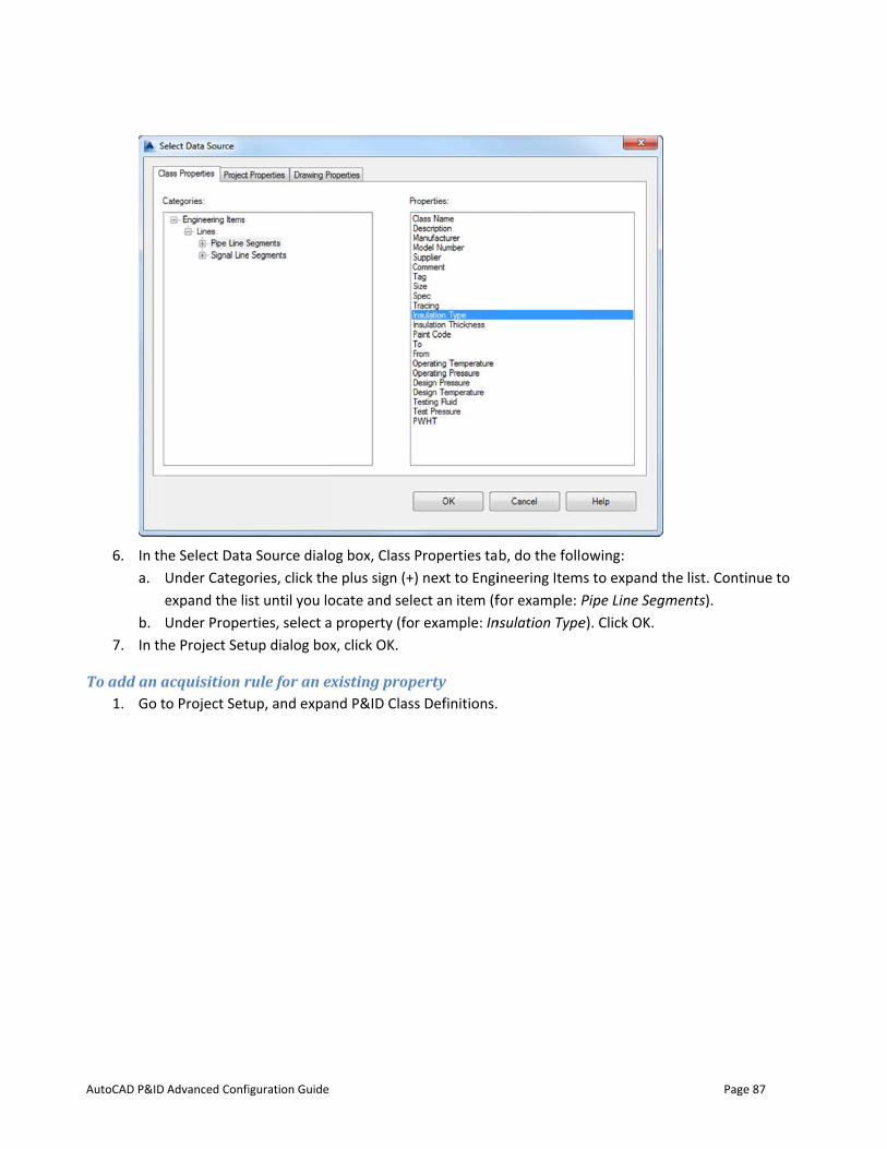
AutoCAD P&ID
6. In tha. U
eb. U
7. In th
To add an a1. Go t
Advanced Confi
he Select DataUnder Categoexpand the lisUnder Proper
he Project Set
acquisition ro Project Set
iguration Guide
a Source dialoories, click thest until you lorties, select atup dialog box
rule for an exup, and expa
og box, Class e plus sign (+ocate and sele property (fox, click OK.
xisting propnd P&ID Class
Properties ta) next to Engiect an item (fr example: In
perty s Definitions.
b, do the follineering Itemfor example:
nsulation Type
owing:
ms to expand tPipe Line Sege). Click OK.
Page
the list. Contigments).
e 87
inue to
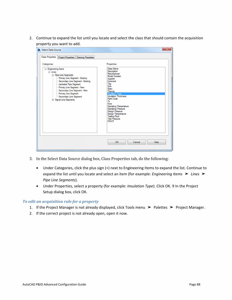
AutoCAD P&ID
2. Contprop
3. In th• U
eP
• US
To edit an a1. If the2. If the
Advanced Confi
tinue to expaperty you wan
he Select DatUnder Categoexpand the lisPipe Line SegUnder ProperSetup dialog
acquisition re Project Mane correct proj
iguration Guide
nd the list unnt to add.
a Source dialories, click thest until you loments). rties, select abox, click OK.
rule for a pronager is not aject is not alr
ntil you locate
log box, Clase plus sign (+ocate and sele
property (fo.
operty already displaeady open, o
e and select th
s Properties ) next to Engiect an item (f
r example: In
ayed, click Toopen it now.
he class that
tab, do the fineering Itemfor example:
nsulation Type
ols menu ➤
should conta
following: ms to expand t
Engineering I
e). Click OK. 9
Palettes ➤
Page
in the acquis
the list. ContiItems ➤ Lin
9 In the Projec
Project Man
e 88
ition
inue to nes ➤
ct
nager.
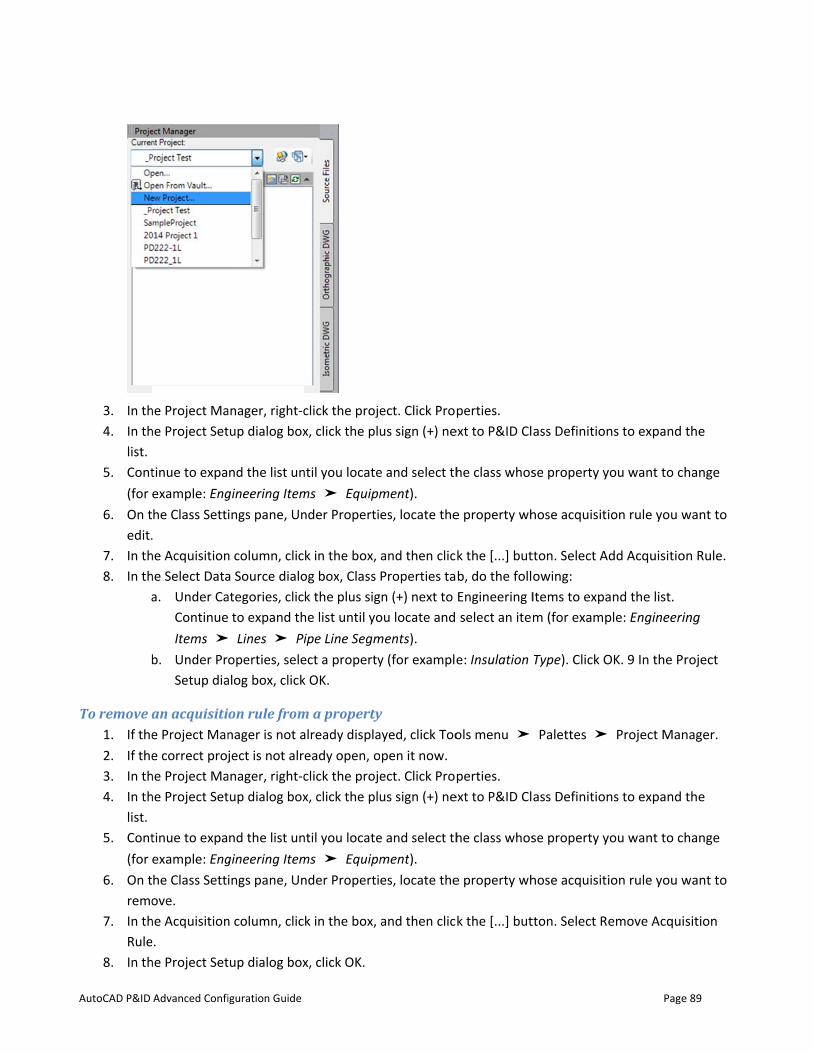
AutoCAD P&ID
3. In th4. In th
list. 5. Cont
(for 6. On t
edit.7. In th8. In th
a
b
To remove a1. If the2. If the3. In th4. In th
list. 5. Cont
(for 6. On t
remo7. In th
Rule8. In th
Advanced Confi
he Project Mahe Project Set
tinue to expaexample: Enghe Class Setti.
he Acquisitionhe Select Dataa. Under Ca
ContinueItems ➤
b. Under PrSetup dia
an acquisitie Project Mane correct proj
he Project Mahe Project Set
tinue to expaexample: Enghe Class Settiove.
he Acquisitione. he Project Set
iguration Guide
anager, right-ctup dialog box
nd the list ungineering Itemings pane, Un
n column, clica Source dialoategories, clic to expand th
➤ Lines ➤ Pioperties, sele
alog box, click
on rule fromnager is not aject is not alr
anager, right-ctup dialog box
nd the list ungineering Itemings pane, Un
n column, clic
tup dialog box
click the projex, click the plu
ntil you locatems ➤ Equipmnder Properti
k in the box, og box, Class k the plus sig
he list until yoipe Line Segm
ect a propertyk OK.
m a propertyalready displaeady open, oclick the projex, click the plu
ntil you locatems ➤ Equipmnder Properti
k in the box,
x, click OK.
ect. Click Prous sign (+) ne
e and select thment). es, locate the
and then clicProperties tan (+) next to
ou locate and ments). y (for example
y ayed, click Toopen it now. ect. Click Prous sign (+) ne
e and select thment). es, locate the
and then clic
perties. ext to P&ID Cl
he class whos
e property wh
k the [...] butb, do the follEngineering I select an ite
e: Insulation
ols menu ➤
perties. ext to P&ID Cl
he class whos
e property wh
k the [...] but
ass Definition
se property y
hose acquisiti
tton. Select Aowing: Items to expam (for examp
Type). Click O
Palettes ➤
ass Definition
se property y
hose acquisiti
tton. Select Re
Page
ns to expand
you want to c
ion rule you w
dd Acquisitio
and the list. ple: Engineeri
OK. 9 In the P
Project Man
ns to expand
you want to c
ion rule you w
emove Acqui
e 89
the
hange
want to
on Rule.
ing
roject
nager.
the
hange
want to
sition

AutoCAD P&ID
To overrideYou can ovesteps describ
1. In a 2. In th3. Click
. In t
4. Ente
5. Clos
NOTE When values of proaccept the chmode.
Advanced Confi
e an acquisiterride an acqbe overriding
drawing, righhe Properties k Acquire Mod
the flyout me
er a new value
e the Propert
you export doperties that hanges, the n
iguration Guide
tion propertyuisition propan acquisitio
ht-click the copalette, locatde
nu, select Ov
e.
ties Palette.
data from theare in Acquire
new values ar
ty erty using th
on property u
omponent whte the proper
verride Mode
Data Manage mode in Exc
re displayed a
he Data Manasing the Prop
ose acquisitiorty you want t
.
er to a Microcel. When yo
and the prope
ager or the Pperties palette
on rule you wto change. Cl
osoft Excel sprou import the erties are auto
Properties pae.
want to overriick the field i
readsheet, yofile into the
omatically ch
Page
alette. The fo
ide. Click Pron the right co
ou can changeData Manage
hanged to Ove
e 90
ollowing
perties. olumn.
e the er and erride
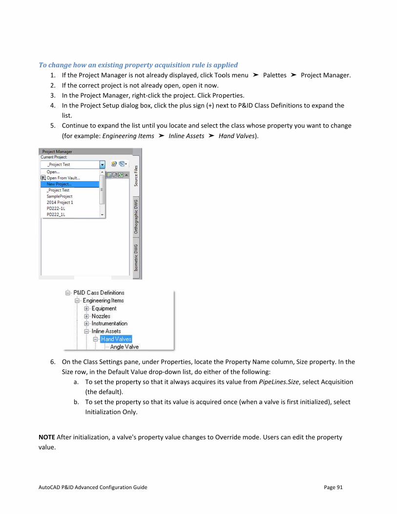
AutoCAD P&ID
To change h1. If the2. If the3. In th4. In th
list. 5. Cont
(for
6. On tSize
a
b
NOTE After ivalue.
Advanced Confi
how an existe Project Mane correct proj
he Project Mahe Project Set
tinue to expaexample: Eng
he Class Settirow, in the Da. To set the
(the defab. To set the
Initializat
nitialization,
iguration Guide
ting propertnager is not aject is not alr
anager, right-ctup dialog box
nd the list ungineering Item
ings pane, unDefault Value e property soult). e property sotion Only.
a valve's prop
ty acquisitioalready displaeady open, oclick the projex, click the plu
ntil you locatems ➤ Inline
nder Propertiedrop-down li
o that it alway
o that its value
perty value c
on rule is appayed, click Toopen it now. ect. Click Prous sign (+) ne
e and select thAssets ➤ H
es, locate thest, do either
ys acquires its
e is acquired
hanges to Ov
plied ols menu ➤
perties. ext to P&ID Cl
he class whosHand Valves).
e Property Naof the follows value from P
once (when a
verride mode.
Palettes ➤
ass Definition
se property y
ame column, Sing: PipeLines.Size
a valve is first
. Users can ed
Page
Project Man
ns to expand
you want to c
Size property
e, select Acqu
t initialized), s
dit the prope
e 91
nager.
the
hange
y. In the
uisition
select
rty

AutoCAD P&ID
In thhas a
7. In th
Set Up Sele
Selection anfor helping twhen you wa
AutoCAD P&apply to you
As part of yo
The selectiondialog box, wGroups, or Swhen it is pla
Be sure to vi
http://apps.e
UnderstandSymbol lists you also defia symbol list
Advanced Confi
he Acquisitiona value of 3, t
he Project Set
ection and Sy
d symbol listso enforce staant designers
&ID provides ar environmen
our project se
n lists you crewhere you deignal Line Groaced from the
sit the Plant 3
exchange.aut
d Symbol Lisare similar toine the symbo have been a
iguration Guide
n column, thethat value aptup dialog box
ymbol Lists
s are used to ndard sizes fo
s to select fro
a set of selectnt. Drafters ca
tup tasks, yo
eate or modiffine the propoups. Those pe tool palette
3D store and
todesk.com/P
sts o selection listol to display fssigned to th
valve size is pears in the Dx, click OK.
control a list or items such
om a predefin
tion lists. Youan also enter
u can set up n
fy populate thperties of Engproperties thee onto a draw
check for plu
PLNT3D/en/L
ts in that youfor a compone current clas
displayed as Data Manage
of predefinedh as piping speed set of opt
can add youtheir own va
new selection
he P&ID Classineering Itemen are include
wing.
ugins that aid
ist/Search?qu
designate a vnent in a P&IDss definition o
acquired fromer for this valv
d selections oecs, piping sizions.
r own items oalues in the lis
n lists or chan
s Definitions dms, Non-Engin
ed in the com
selection list
uery=selectio
value for a prD drawing. Thor inherited f
m PipeLines.Sve.
of choices. Thzes, and instr
or delete itemsts in the Dat
nge the value
data in the Prneering Itemsmponent or lin
t customizatio
on+lists
roperty. But whe symbols thfrom a class d
Page
Size. If PipeLin
hese lists are urument types
ms that don’t a Manager.
s of an existin
roject Setup , Pipe Line ne behavior
on.
with a symboat you can se
definition fam
e 92
nes.Size
useful , or
ng one.
l list, elect for
mily.

AutoCAD P&ID
Procedures
To create a 1. If the2. If the3. In th4. In th
to ex5. Cont
exam
6. In th
7. In th
Und
Belonam
Advanced Confi
s: Set Up Sel
selection lise Project Mane correct proj
he Project Mahe Project Setxpand the listtinue to expample: Enginee
he Properties
he Add Proper
er Type, selec
ow Property Ne cannot con
iguration Guide
ection and S
st nager is not aject is not alr
anager, tree vtup dialog boxt. nd the list un
ering Items).
group, click A
rty dialog box
ct Selection L
Name, enter antain any spac
Symbol Lists
already displaeady open, o
view, right-clicx, Project Sett
ntil you locate
Add.
x, do the follo
List.
a name for thces.
s
ayed, click Toopen it now. ck the projecttings, click th
e and select a
owing;
e new proper
ols menu ➤
t folder. Clickhe plus sign (+
component
rty (for exam
Palettes ➤
k Properties. +) next to P&I
or line class d
ple: Pump_M
Page
Project Man
D Class Defin
definition (for
Manufacturers
e 93
nager.
nitions
r
s). The
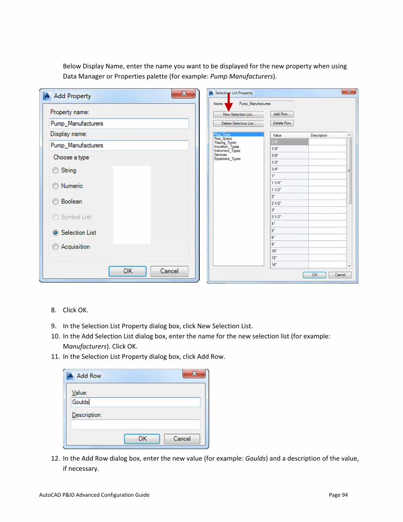
AutoCAD P&ID
BeloData
8. Click
9. In th10. In th
Man11. In th
12. In thif ne
Advanced Confi
ow Display Naa Manager or
k OK.
he Selection Lhe Add Selectnufacturers). Che Selection L
he Add Row dcessary.
iguration Guide
me, enter theProperties pa
List Property dion List dialogClick OK.
List Property d
ialog box, ent
e name you walette (for ex
dialog box, clig box, enter t
dialog box, cli
ter the new v
want to be disample: Pump
ick New Selecthe name for
ick Add Row.
value (for exa
splayed for thp Manufactur
ction List. the new sele
ample: Goulds
he new properers).
ection list (for
s) and a descr
Page
erty when usi
r example:
ription of the
e 94
ng
e value,
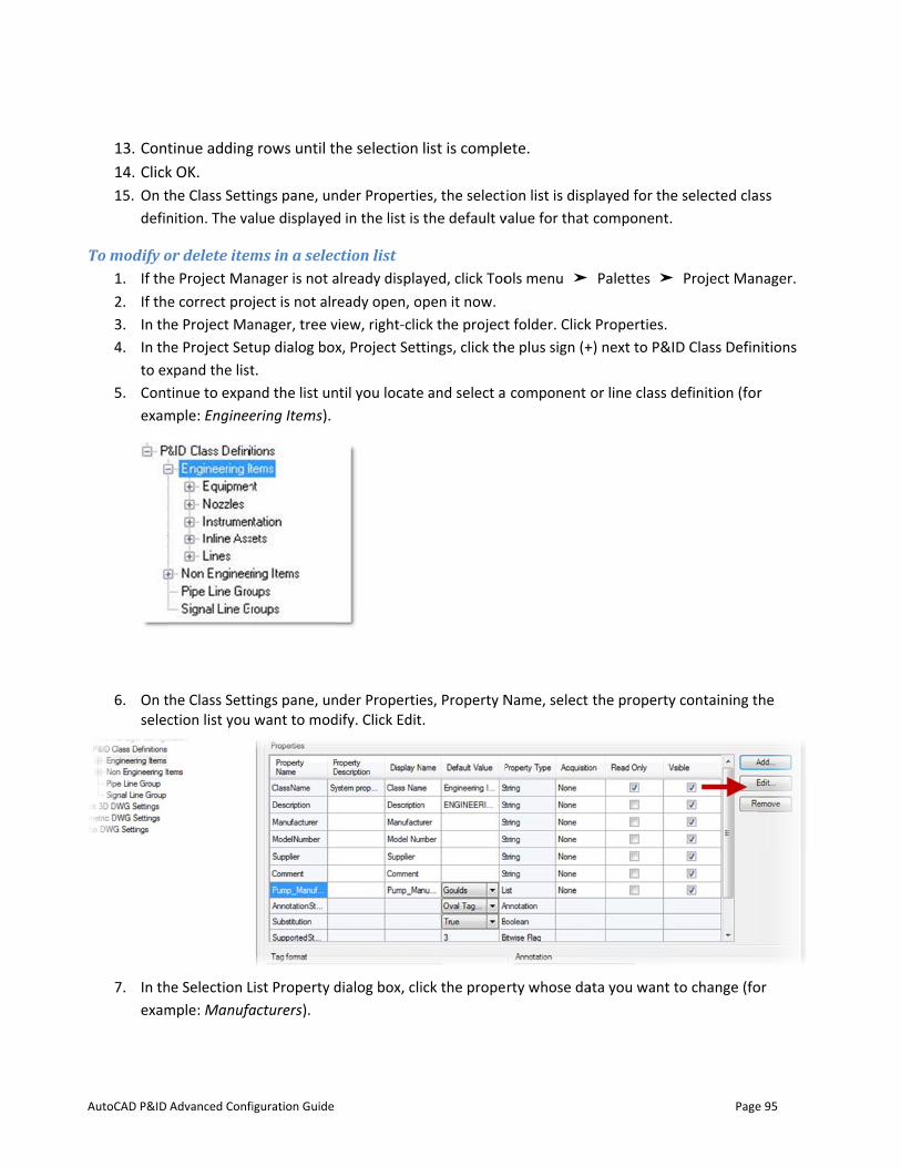
AutoCAD P&ID
13. Cont14. Click15. On t
defin
To modify o1. If the2. If the3. In th4. In th
to ex5. Cont
exam
6. On tselec
7. In thexam
Advanced Confi
tinue addingk OK. he Class Settinition. The va
or delete iteme Project Mane correct proj
he Project Mahe Project Setxpand the listtinue to expample: Enginee
he Class Settiction list you
he Selection Lmple: Manufa
iguration Guide
g rows until th
ings pane, unalue displayed
ms in a selecnager is not aject is not alr
anager, tree vtup dialog boxt. nd the list un
ering Items).
ings pane, unwant to mod
List Property dacturers).
he selection
nder Propertied in the list is
ction list already displaeady open, o
view, right-clicx, Project Sett
ntil you locate
nder Propertiedify. Click Edit
dialog box, cli
list is comple
es, the selectthe default v
ayed, click Toopen it now. ck the projecttings, click th
e and select a
es, Property N.
ick the prope
ete.
ion list is dispvalue for that
ols menu ➤
t folder. Clickhe plus sign (+
component
Name, select
rty whose da
played for thecomponent.
Palettes ➤
k Properties. +) next to P&I
or line class d
the property
ata you want t
Page
e selected cla
Project Man
D Class Defin
definition (for
y containing t
to change (fo
e 95
ss
nager.
nitions
r
he
or
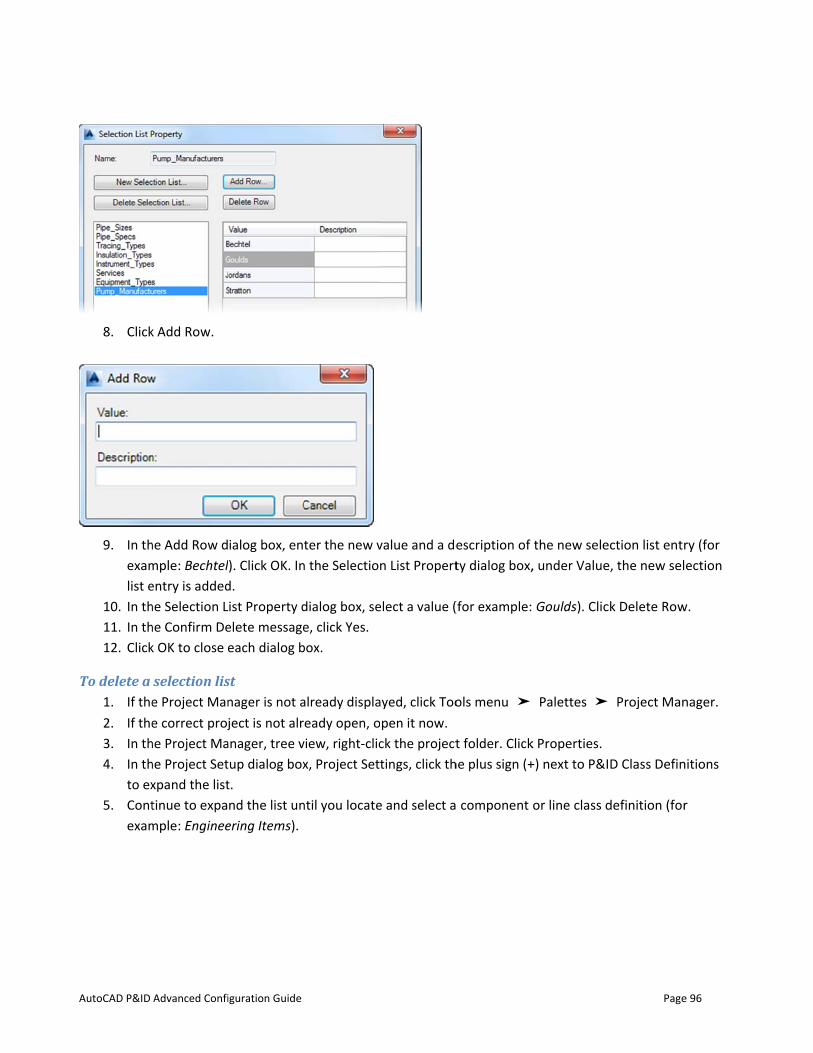
AutoCAD P&ID
8. Click
9. In thexamlist e
10. In th11. In th12. Click
To delete a 1. If the2. If the3. In th4. In th
to ex5. Cont
exam
Advanced Confi
k Add Row.
he Add Row dmple: Bechtelentry is addedhe Selection Lhe Confirm Dek OK to close e
selection lise Project Mane correct proj
he Project Mahe Project Setxpand the listtinue to expample: Enginee
iguration Guide
ialog box, entl). Click OK. Ind. List Property delete messageeach dialog b
st nager is not aject is not alr
anager, tree vtup dialog boxt. nd the list un
ering Items).
ter the new vn the Selection
dialog box, see, click Yes.
box.
already displaeady open, o
view, right-clicx, Project Sett
ntil you locate
value and a den List Propert
elect a value (
ayed, click Toopen it now. ck the projecttings, click th
e and select a
escription of ty dialog box,
(for example:
ols menu ➤
t folder. Clickhe plus sign (+
component
the new sele, under Value
Goulds). Clic
Palettes ➤
k Properties. +) next to P&I
or line class d
Page
ection list entre, the new sel
ck Delete Row
Project Man
D Class Defin
definition (for
e 96
ry (for ection
w.
nager.
nitions
r
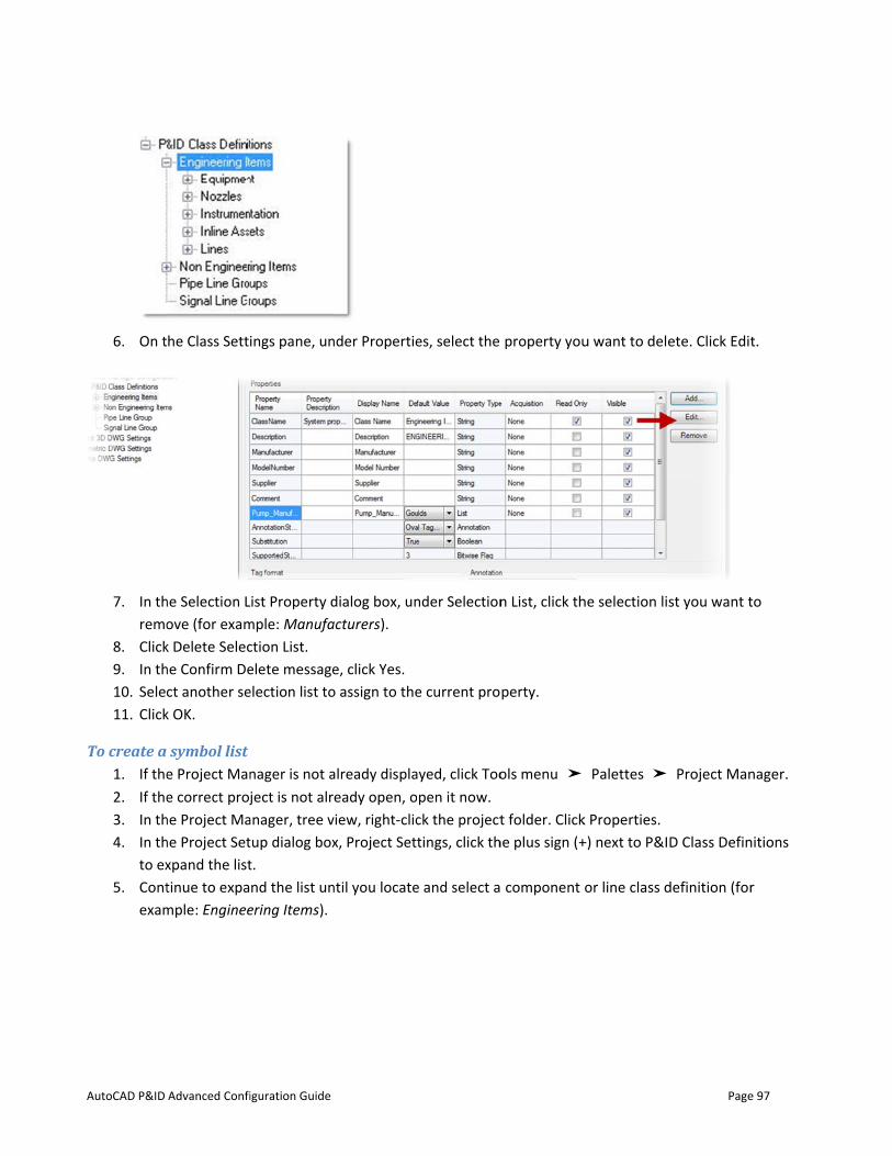
AutoCAD P&ID
6. On t
7. In thremo
8. Click9. In th10. Sele11. Click
To create a 1. If the2. If the3. In th4. In th
to ex5. Cont
exam
Advanced Confi
he Class Setti
he Selection Love (for exam
k Delete Seleche Confirm Dect another se
k OK.
symbol list e Project Mane correct proj
he Project Mahe Project Setxpand the listtinue to expample: Enginee
iguration Guide
ings pane, un
List Property dmple: Manufaction List. elete messageelection list to
nager is not aject is not alr
anager, tree vtup dialog boxt. nd the list un
ering Items).
nder Propertie
dialog box, unacturers).
e, click Yes. o assign to the
already displaeady open, o
view, right-clicx, Project Sett
ntil you locate
es, select the
nder Selection
e current pro
ayed, click Toopen it now. ck the projecttings, click th
e and select a
property you
n List, click th
perty.
ols menu ➤
t folder. Clickhe plus sign (+
component
u want to del
he selection li
Palettes ➤
k Properties. +) next to P&I
or line class d
Page
ete. Click Edit
st you want t
Project Man
D Class Defin
definition (for
e 97
t.
to
nager.
nitions
r
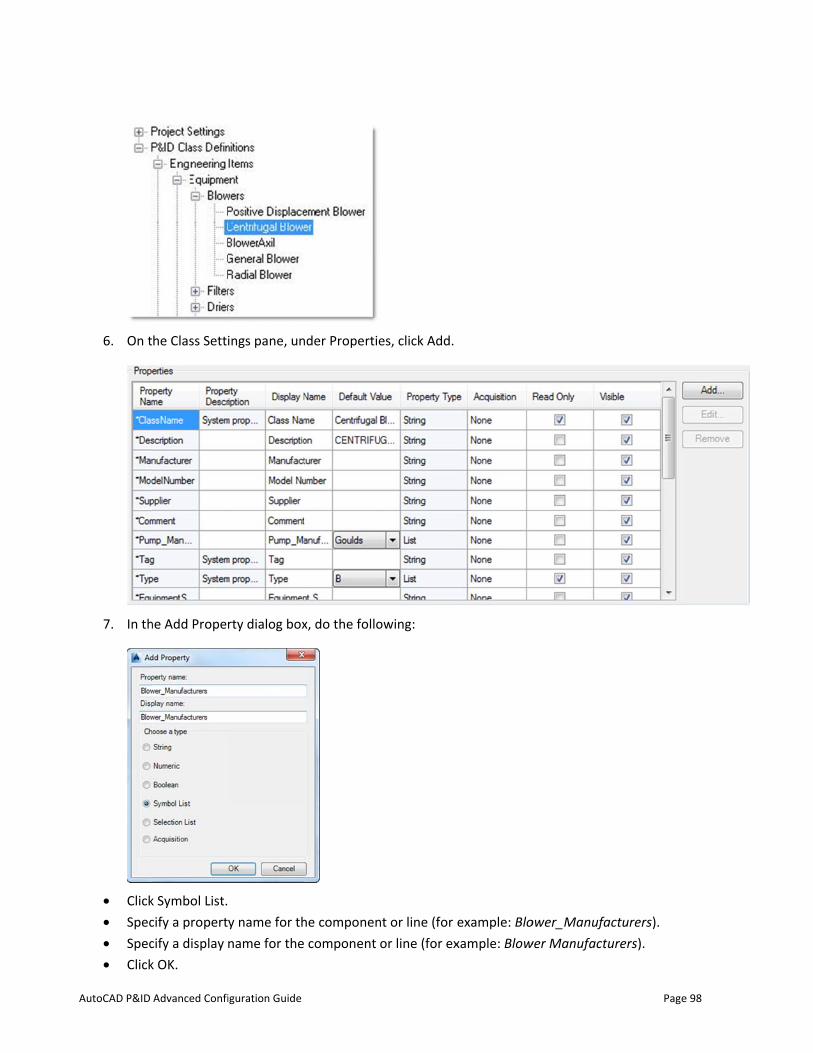
AutoCAD P&ID
6. On t
7. In th
• Click• Spec• Spec• Click
Advanced Confi
he Class Setti
he Add Proper
k Symbol List.cify a propertcify a display k OK.
iguration Guide
ings pane, un
rty dialog box
y name for thname for the
nder Propertie
x, do the follo
he componen component
es, click Add.
owing:
nt or line (foror line (for ex
example: Bloxample: Blow
ower_Manufawer Manufactu
Page
acturers). urers).
e 98
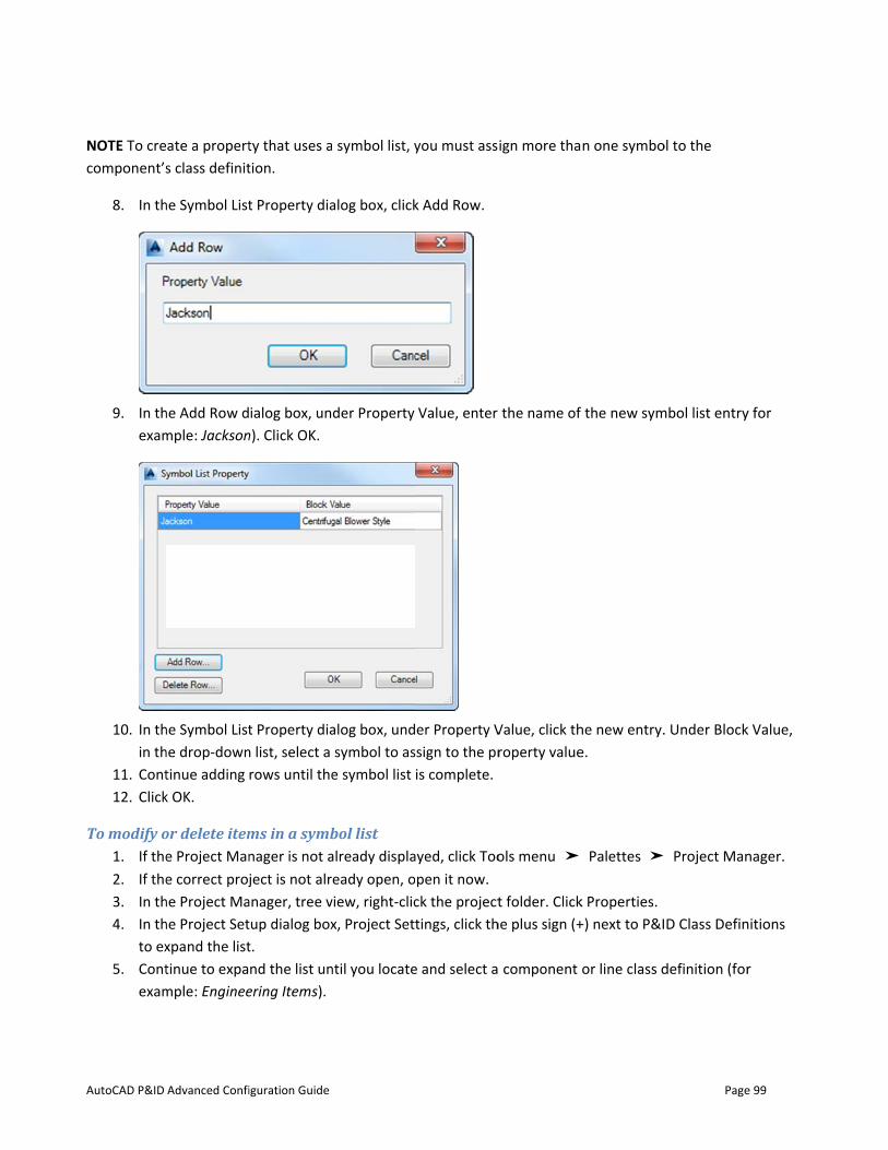
AutoCAD P&ID
NOTE To crecomponent’s
8. In th
9. In thexam
10. In thin th
11. Cont12. Click
To modify o1. If the2. If the3. In th4. In th
to ex5. Cont
exam
Advanced Confi
ate a properts class definit
he Symbol List
he Add Row dmple: Jackson
he Symbol Listhe drop-downtinue adding k OK.
or delete iteme Project Mane correct proj
he Project Mahe Project Setxpand the listtinue to expample: Enginee
iguration Guide
ty that uses ation.
t Property dia
ialog box, unn). Click OK.
t Property dian list, select a rows until the
ms in a symbnager is not aject is not alr
anager, tree vtup dialog boxt. nd the list un
ering Items).
symbol list, y
alog box, click
der Property
alog box, undsymbol to as
e symbol list
bol list already displaeady open, o
view, right-clicx, Project Sett
ntil you locate
you must ass
k Add Row.
Value, enter
er Property V
ssign to the pris complete.
ayed, click Toopen it now. ck the projecttings, click th
e and select a
ign more tha
the name of
Value, click throperty value
ols menu ➤
t folder. Clickhe plus sign (+
component
n one symbo
the new sym
he new entry.e.
Palettes ➤
k Properties. +) next to P&I
or line class d
Page
ol to the
mbol list entry
. Under Block
Project Man
D Class Defin
definition (for
e 99
y for
k Value,
nager.
nitions
r
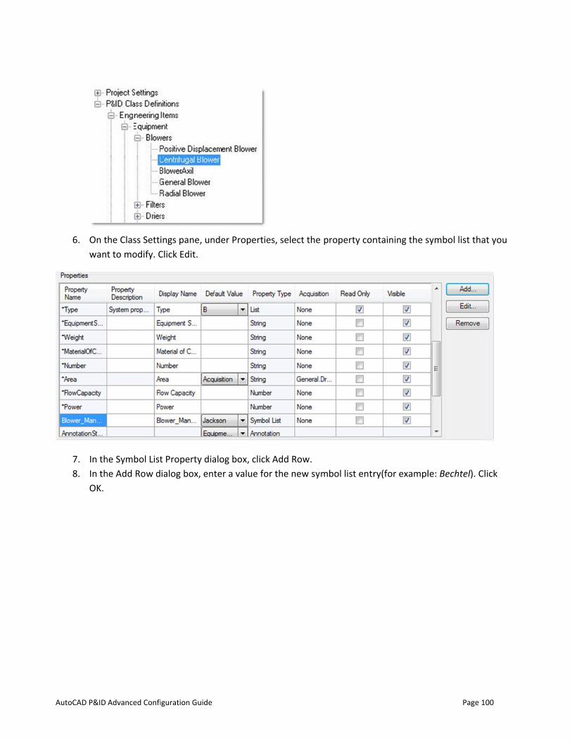
AutoCAD P&ID
6. On twan
7. In th8. In th
OK.
Advanced Confi
he Class Settit to modify. C
he Symbol Listhe Add Row d
iguration Guide
ings pane, unClick Edit.
t Property diaialog box, ent
nder Propertie
alog box, clickter a value fo
es, select the
k Add Row. or the new sym
property con
mbol list entr
ntaining the s
ry(for exampl
Page
symbol list tha
le: Bechtel). C
100
at you
Click
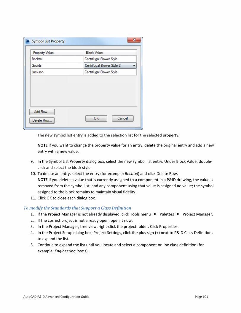
AutoCAD P&ID
The
NOTentry
9. In thclick
10. To dNOTremoassig
11. Click
To modify t1. If the2. If the3. In th4. In th
to ex5. Cont
exam
Advanced Confi
new symbol l
TE If you wanty with a new
he Symbol Listk and select th
elete an entrTE If you deletoved from thgned to the bk OK to close e
the Standarde Project Mane correct proj
he Project Mahe Project Setxpand the listtinue to expample: Enginee
iguration Guide
list entry is ad
t to change thvalue.
t Property diahe block stylery, select the ete a value thae symbol list,lock remains each dialog b
ds that Suppnager is not aject is not alr
anager, tree vtup dialog boxt. nd the list un
ering Items).
dded to the s
he property v
alog box, selee. entry (for exa
at is currently, and any comto maintain v
box.
port a Class Dalready displaeady open, o
view, right-clicx, Project Sett
ntil you locate
election list f
value for an e
ect the new sy
ample: Bechtey assigned to amponent usingvisual fidelity
Definition ayed, click Toopen it now. ck the projecttings, click th
e and select a
for the selecte
ntry, delete t
ymbol list ent
el) and click Da componentg that value i
y.
ols menu ➤
t folder. Clickhe plus sign (+
component
ed property.
the original en
try. Under Blo
Delete Row. t in a P&ID drs assigned no
Palettes ➤
k Properties. +) next to P&I
or line class d
Page
ntry and add
ock Value, do
rawing, the vao value; the sy
Project Man
D Class Defin
definition (for
101
a new
ouble-
alue is ymbol
nager.
nitions
r
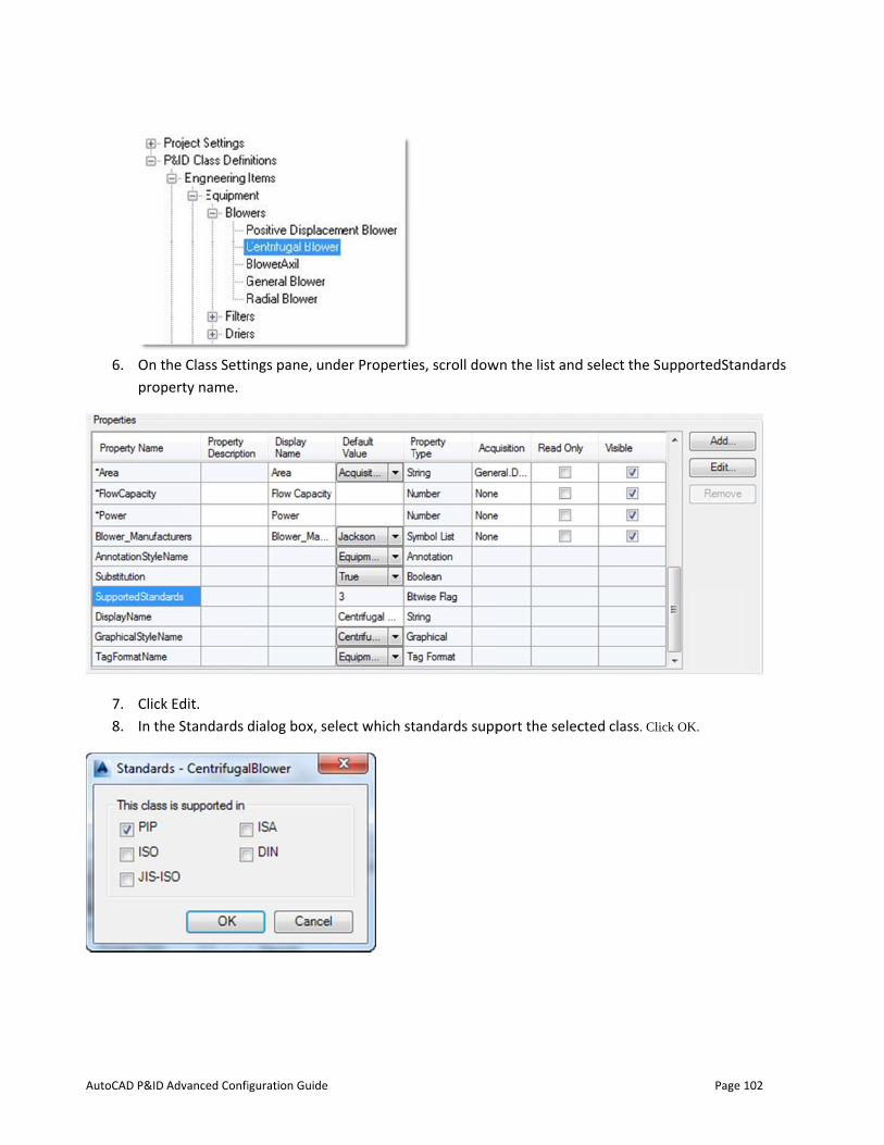
AutoCAD P&ID
6. On tprop
7. Click8. In th
Advanced Confi
he Class Settiperty name.
k Edit. he Standards d
iguration Guide
ings pane, un
dialog box, se
nder Propertie
elect which st
es, scroll dow
tandards supp
wn the list and
port the selec
d select the S
cted class. Cli
Page
upportedStan
ick OK.
102
ndards
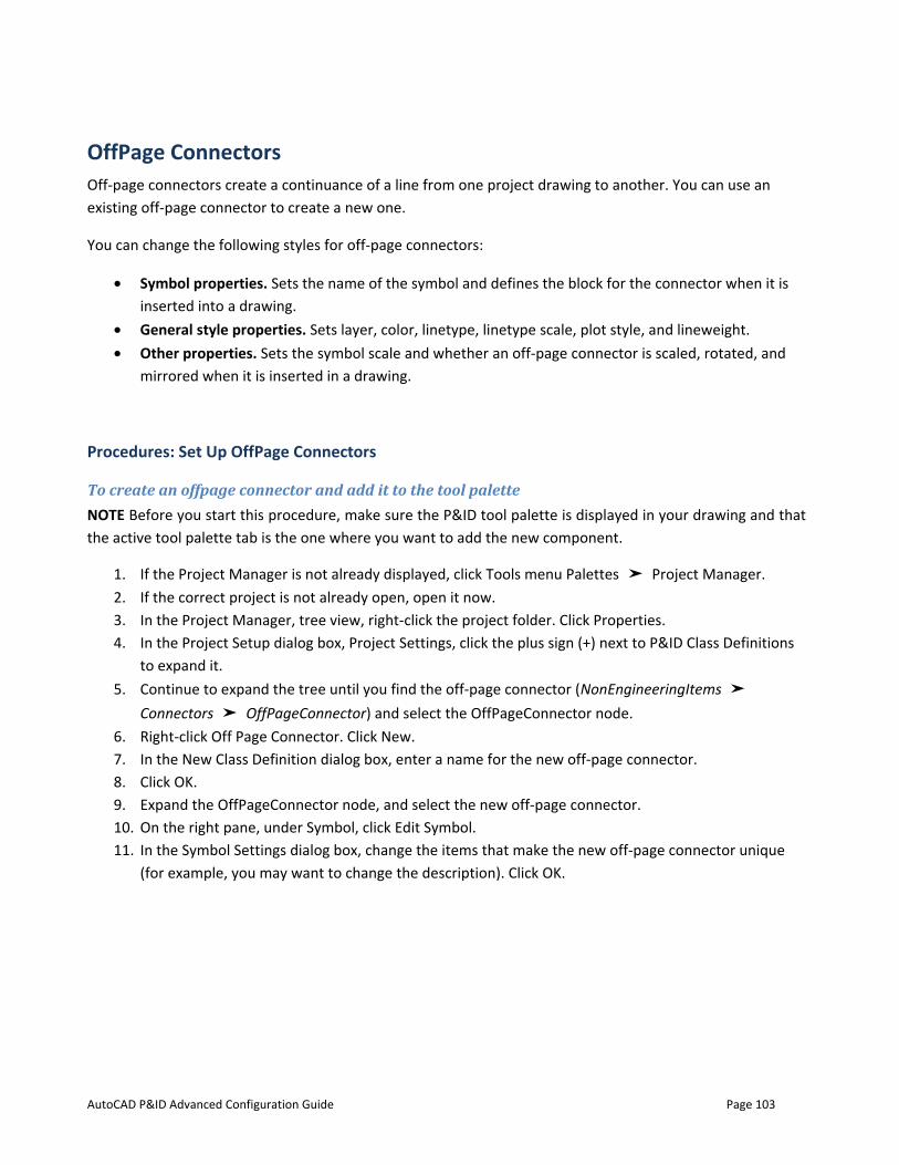
AutoCAD P&ID Advanced Configuration Guide Page 103
OffPage Connectors Off-page connectors create a continuance of a line from one project drawing to another. You can use an existing off-page connector to create a new one.
You can change the following styles for off-page connectors:
• Symbol properties. Sets the name of the symbol and defines the block for the connector when it is inserted into a drawing.
• General style properties. Sets layer, color, linetype, linetype scale, plot style, and lineweight. • Other properties. Sets the symbol scale and whether an off-page connector is scaled, rotated, and
mirrored when it is inserted in a drawing.
Procedures: Set Up OffPage Connectors
To create an offpage connector and add it to the tool palette NOTE Before you start this procedure, make sure the P&ID tool palette is displayed in your drawing and that the active tool palette tab is the one where you want to add the new component.
1. If the Project Manager is not already displayed, click Tools menu Palettes ➤ Project Manager. 2. If the correct project is not already open, open it now. 3. In the Project Manager, tree view, right-click the project folder. Click Properties. 4. In the Project Setup dialog box, Project Settings, click the plus sign (+) next to P&ID Class Definitions
to expand it. 5. Continue to expand the tree until you find the off-page connector (NonEngineeringItems ➤
Connectors ➤ OffPageConnector) and select the OffPageConnector node. 6. Right-click Off Page Connector. Click New. 7. In the New Class Definition dialog box, enter a name for the new off-page connector. 8. Click OK. 9. Expand the OffPageConnector node, and select the new off-page connector. 10. On the right pane, under Symbol, click Edit Symbol. 11. In the Symbol Settings dialog box, change the items that make the new off-page connector unique
(for example, you may want to change the description). Click OK.
AutoCAD P&ID
12. UndOffP
13. Clickdefa
14. Click
Advanced Confi
er Symbol, inPageConnectok Add to Tool ult tools prov
k OK.
iguration Guide
the drop-doworStyle2).
Palette. The vided with Au
wn list, locate
new style is autoCAD P&ID,
e the style yo
added to the , and will be i
ou just create
active tool pancluded in re
d (in this exa
alette. It can eports.
Page
mple,
be used just l
104
like the

AutoCAD P&ID Advanced Configuration Guide Page 105
SQL Server The decision to use SQL Server is driven by the number of users modifying project data at one time. The default database type, SQLite is valid for up to 2 TB per file, so the project file size is not the issue. Because the SQLite database is a single file, successful read/writes depend on fast access. When more users access the database at one time, they have a higher chance of hitting the database at the same time (or close enough).
Due to network configurations, server performance, computer performance, network loads, and a host of other factors, a precise number of users cannot be given. However, through experience with various clients, most people start to see performance degradation with between 6 - 10 users.
If you know you will have more than 10 active users, you should implement SQL Server Express or SQL Server.
You must also use SQL Server if you plan to use Plant 3D with Vault.
Database Types SQL Server – An enterprise-level product offering from Microsoft that includes a database server with administration tools for replicating databases between sites, and other advanced features
SQL Server Express – A free product offering from Microsoft that includes a database server without advanced administration tools. You can still configure backups.
SQLite – An open source file-based database used by developers world-wide. The database engine is fast with good performance.
Versions AutoCAD Plant 3D has been run with SQL Server 2005, SQL Server 2008, and SQL Server 2012.
Articles on setting up SQL Server Express and creating backups are available here:
http://www.pdoteam.com/series/plant3d-on-sql-express/
AutoCAD P&ID Advanced Configuration Guide Page 106
Vault Autodesk Vault (http://www.autodesk.com/products/autodesk-vault-family/features ) is document management software that integrates with many products in the Autodesk portfolio. In 2014, Vault became integrated into the Plant Project Manager.
Vault should be used in the following conditions:
• You have multiple sites that need to share data • You can use SQL Server or SQL Server Express.
Vault allows you to store the drawing data in a central location, and have satellite offices check in/out drawings on an as-needed basis. Currently, all xrefs must reside within the project structure, as Plant uses its own working directory for Vaulted projects.

AutoCAD P&ID Advanced Confiiguration Guide Page 107
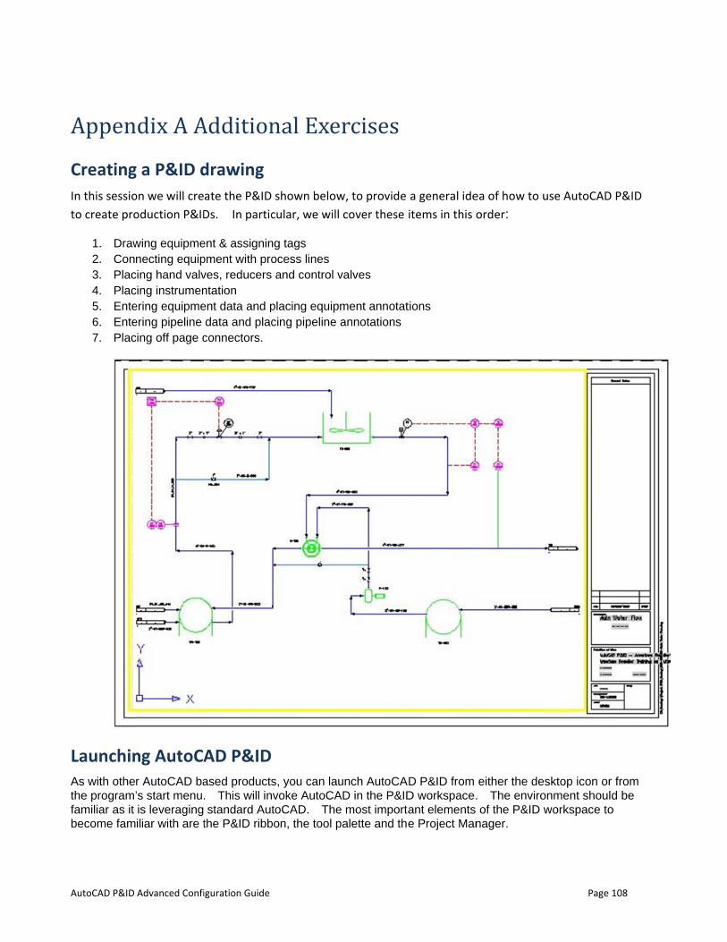
AutoCAD P&ID
AppenCreatingIn this sessioto create pro
1. Draw2. Con3. Plac4. Plac5. Ente6. Ente7. Plac
LaunchinAs with othethe program’familiar as it become fam
Advanced Confi
dix A Ag a P&ID don we will creoduction P&ID
wing equipmenecting equip
cing hand valvcing instrumenering equipmeering pipeline cing off page c
ng AutoCAr AutoCAD ba’s start menu.is leveragingiliar with are t
iguration Guide
Additiondrawing ate the P&IDDs. In partic
ent & assigninpment with proves, reducers ntation ent data and pdata and placconnectors.
AD P&ID ased products. This will instandard Aut
the P&ID ribb
nal Exe shown below
cular, we will
ng tags ocess lines and control v
placing equipmcing pipeline
s, you can lauvoke AutoCAtoCAD. The
bon, the tool p
rcisesw, to provide
cover these
valves
ment annotatannotations
unch AutoCAAD in the P&IDe most importapalette and the
a general ideitems in this o
tions
D P&ID from D workspace.ant elements e Project Man
ea of how to uorder:
either the de. The enviro of the P&ID wnager.
Page
use AutoCAD
sktop icon or onment shouldworkspace to
108
P&ID
r from d be
o
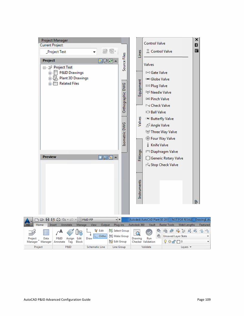
AutoCAD P&ID Advanced Confiiguration Guide
Page
109
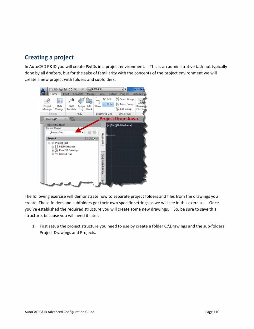
AutoCAD P&ID
CreatingIn AutoCAD done by all dcreate a new
The followincreate. Thesyou’ve estabstructure, be
1. FirstProje
Advanced Confi
g a projecP&ID you will
drafters, but fw project with
g exercise wie folders and
blished the reecause you w
setup the prect Drawings
iguration Guide
t l create P&IDfor the sake oh folders and
ll demonstrat subfolders gquired structill need it late
oject structuand Projects
s in a projectof familiarity wsubfolders.
te how to sepet their own ure you will cer.
re you need t.
environmentwith the conc
parate projectspecific settin
create some n
to use by crea
t. This is ancepts of the p
t folders and ngs as we wilnew drawings
ate a folder C
n administratiproject enviro
files from thel see in this es. So, be su
C:\Drawings a
Page
ve task not tyonment we w
e drawings yoexercise. Onre to save thi
nd the sub-fo
110
ypically ill
ou nce is
olders
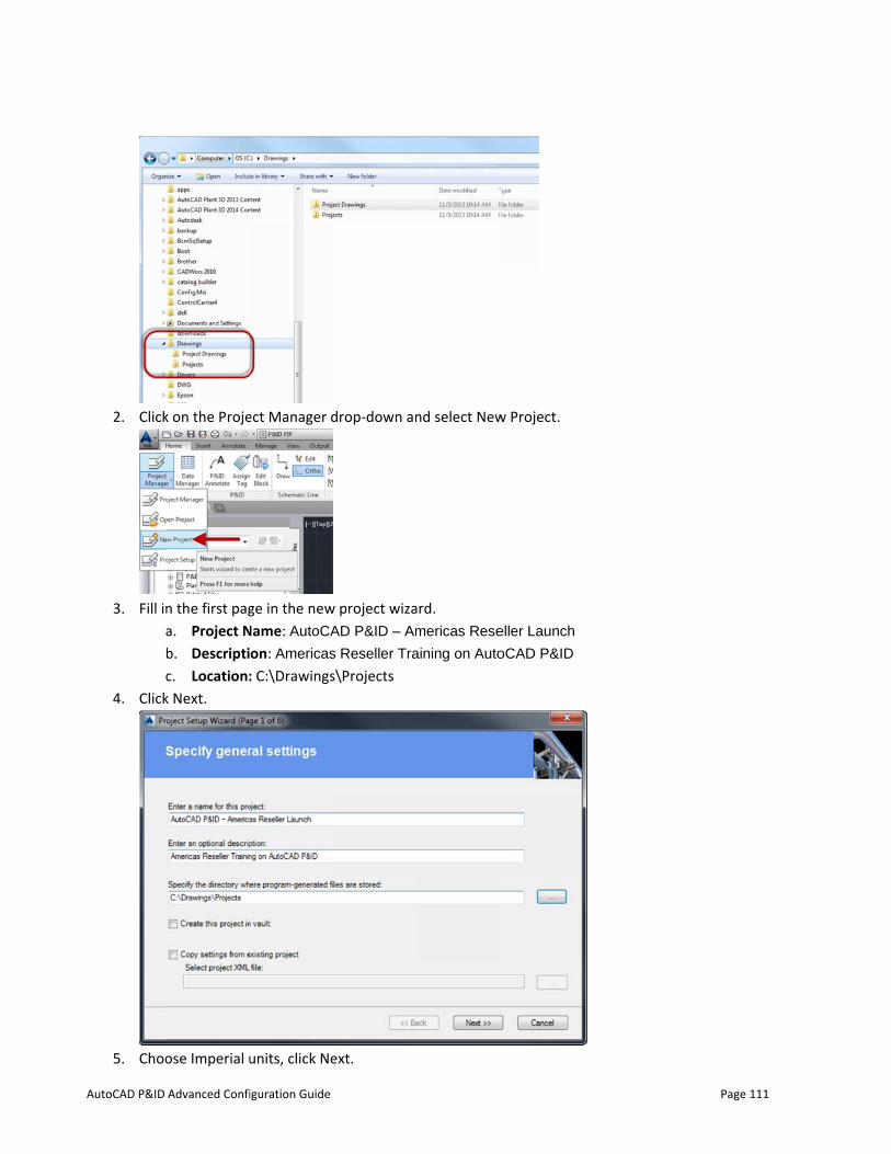
AutoCAD P&ID
2. Click
3. Fill inabc
4. Click
5. Choo
Advanced Confi
k on the Proje
n the first paga. Project Nb. Descriptic. Location:k Next.
ose Imperial u
iguration Guide
ect Manager d
ge in the new
Name: AutoCA
on: Americas
: C:\Drawings
units, click Ne
drop-down an
w project wizaAD P&ID – Am
s Reseller Tra
s\Projects
ext.
nd select New
ard. mericas Rese
aining on Auto
w Project.
eller Launch
oCAD P&ID
Page 111
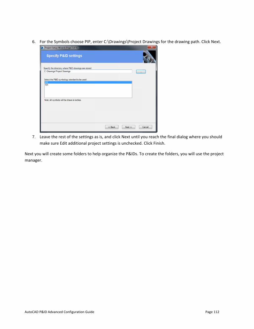
AutoCAD P&ID
6. For t
7. Leavmak
Next you wilmanager.
Advanced Confi
the Symbols c
ve the rest of e sure Edit ad
l create some
iguration Guide
choose PIP, e
the settings additional proj
e folders to h
nter C:\Draw
as is, and clickect settings i
elp organize t
wings\Project
k Next until ys unchecked.
the P&IDs. To
Drawings for
you reach the Click Finish.
o create the f
the drawing
final dialog w
folders, you w
Page
path. Click N
where you sh
will use the pr
112
ext.
ould
roject
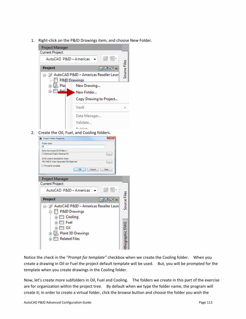
AutoCAD P&ID
1. Righ
2. Crea
Notice the chcreate a drawtemplate wh
Now, let’s crare for organcreate it; in o
Advanced Confi
t-click on the
ate the Oil, Fu
heck in the “Pwing in Oil orhen you creat
reate more sunization withiorder to creat
iguration Guide
e P&ID Drawin
uel, and Cooli
Prompt for te Fuel the proje drawings in
ubfolders in Oin the projectte a virtual fo
ngs item, and
ng folders.
mplate” checject default te
n the Cooling
Oil, Fuel and Ct tree. By deolder, click the
choose New
ckbox when wemplate will folder.
Cooling. Theefault when we browse but
w Folder.
we create thebe used. Bu
e folders we cwe type the fotton and choo
e Cooling foldut, you will be
create in this older name, tose the folder
Page
er. When ye prompted f
part of the exthe program wr you wish the
113
ou or the
xercise will e
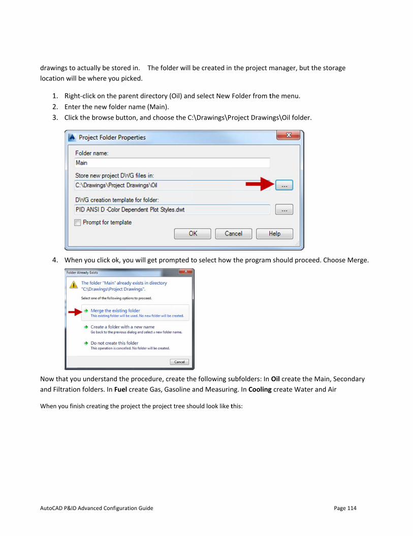
AutoCAD P&ID
drawings to location will
1. Righ2. Ente3. Click
4. Whe
Now that yoand Filtratio
When you fin
Advanced Confi
actually be stbe where yo
t-click on theer the new folk the browse
en you click o
u understandn folders. In F
ish creating th
iguration Guide
tored in. Thu picked.
e parent direclder name (Mbutton, and c
k, you will ge
d the proceduFuel create G
e project the p
e folder will b
ctory (Oil) andMain).
choose the C:
t prompted t
ure, create thas, Gasoline a
project tree sho
be created in
d select New
\Drawings\P
o select how
e following suand Measurin
ould look like t
the project m
Folder from t
roject Drawin
the program
ubfolders: Inng. In Cooling
this:
manager, but
the menu.
ngs\Oil folder
m should proce
Oil create thg create Wate
Page
t the storage
r.
eed. Choose
e Main, Secoer and Air
114
Merge.
ndary
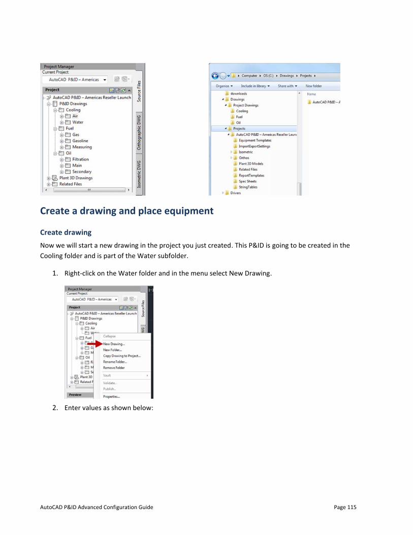
AutoCAD P&ID
Create a
Create drawNow we will Cooling folde
1. Righ
2. Ente
Advanced Confi
drawing
wing start a new d
er and is part
t-click on the
er values as sh
iguration Guide
g and plac
drawing in the of the Water
e Water folde
hown below:
ce equipm
e project your subfolder.
r and in the m
ment
just created.
menu select N
. This P&ID is
New Drawing
going to be c
.
Page
created in the
115
e
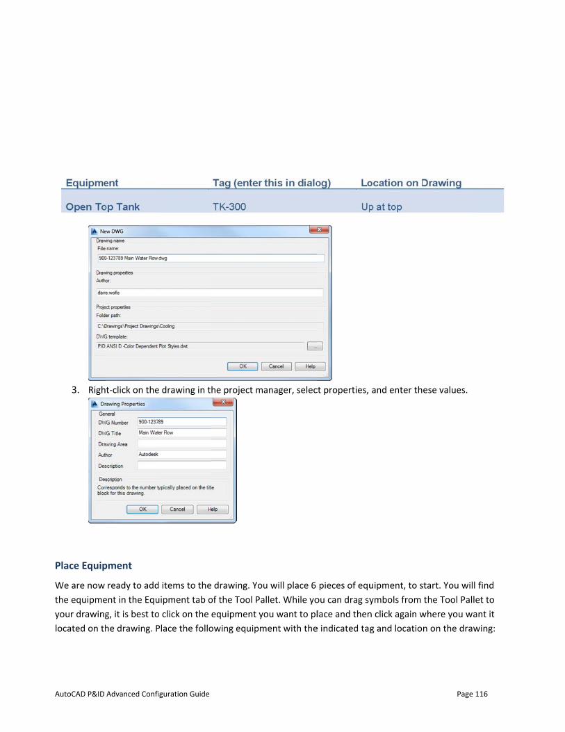
AutoCAD P&ID
3. Righ
Place Equip
We are now the equipmeyour drawinglocated on th
Advanced Confi
t-click on the
pment
ready to addent in the Equg, it is best tohe drawing. P
iguration Guide
e drawing in t
d items to theuipment tab oo click on the Place the follo
he project ma
drawing. Youof the Tool Paequipment yo
owing equipm
anager, selec
u will place 6 allet. While yoou want to pl
ment with the
ct properties,
pieces of equou can drag sylace and then
e indicated tag
and enter th
uipment, to symbols from n click again wg and locatio
Page
ese values.
start. You willthe Tool Palle
where you wan on the draw
116
find et to ant it wing:
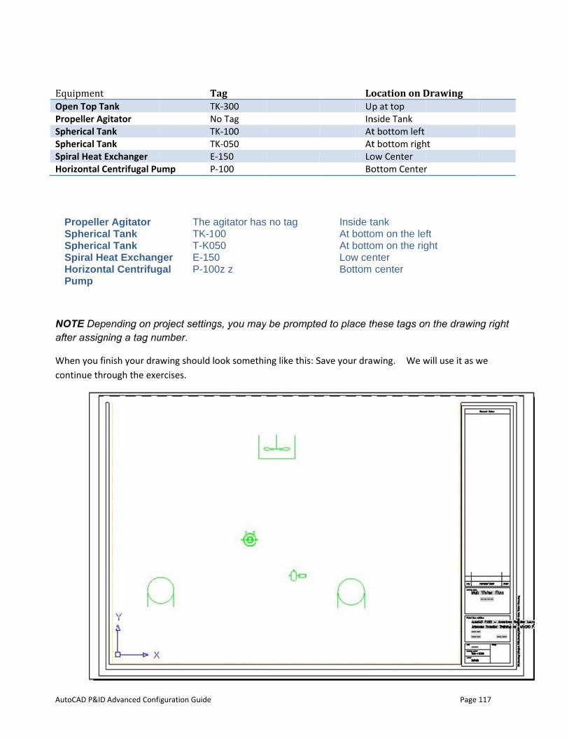
AutoCAD P&ID
Equipment Open Top TaPropeller AgSpherical TaSpherical TaSpiral Heat EHorizontal C
NOTE Depeafter assign
When you ficontinue thr
PropellerSphericaSphericaSpiral HeHorizontaPump
Advanced Confi
ank gitator nk nk
Exchanger Centrifugal Pu
ending on prning a tag nu
nish your draough the exe
r Agitator al Tank al Tank eat Exchangal Centrifug
iguration Guide
TTNTTE
ump P
roject settingumber.
wing should ercises.
The TK-1T-K0
ger E-15gal P-10
Tag TK-300 No Tag TK-100 TK-050 E-150 P-100
gs, you may
look somethi
agitator has00
050 50 00z z
y be prompte
ng like this: S
no tag
LoUpInAtAtLoBo
ed to place th
Save your dra
Inside tAt bottoAt bottoLow ceBottom
ocation on Dp at top
nside Tank t bottom left t bottom righow Center ottom Center
hese tags on
wing. We w
tank om on the lefom on the rignter center
Page
Drawing
ht
r
n the drawin
will use it as w
ft ght
117
ng right
we
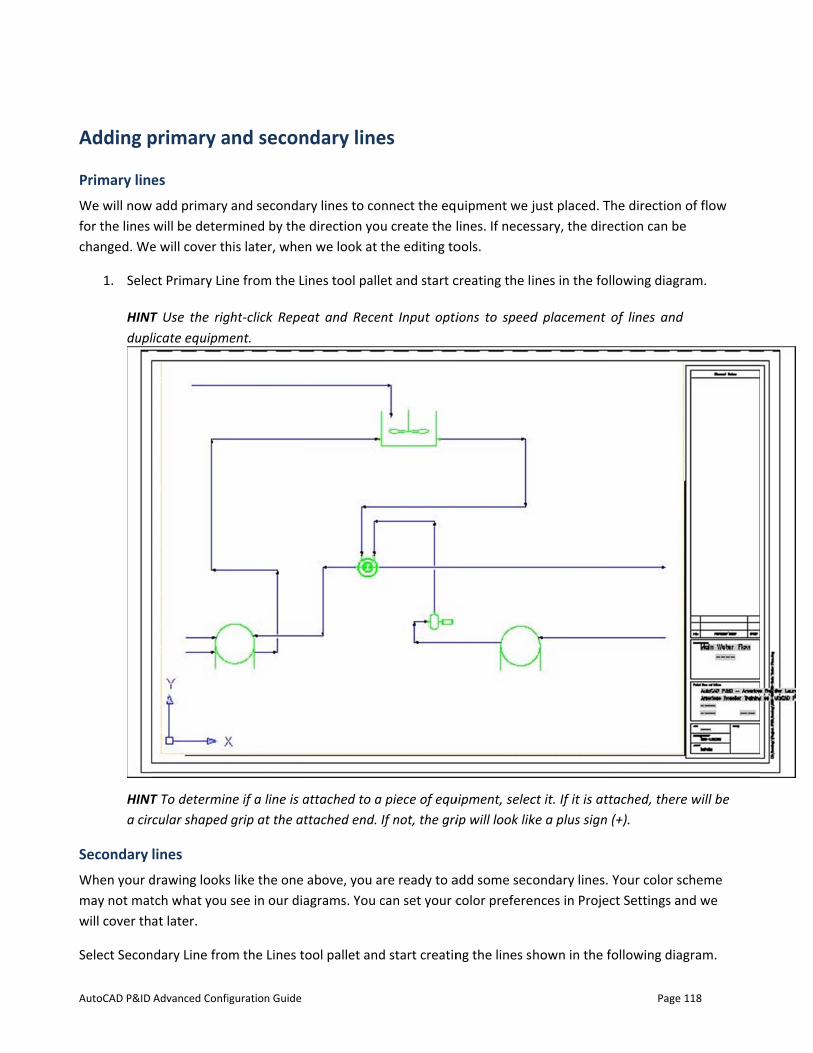
AutoCAD P&ID
Adding p
Primary lineWe will nowfor the lines changed. We
1. Sele
HINTdupl
HINTa cir
Secondary When your dmay not matwill cover th
Select Secon
Advanced Confi
primary a
es add primary will be deter
e will cover th
ct Primary Lin
T Use the riglicate equipm
T To determinrcular shaped
lines drawing lookstch what you at later.
ndary Line fro
iguration Guide
and secon
and secondamined by thehis later, whe
ne from the L
ght‐click Repement.
ne if a line is agrip at the a
s like the one see in our dia
m the Lines t
ndary line
ary lines to coe direction yon we look at
Lines tool pall
eat and Rece
attached to attached end.
above, you aagrams. You c
ool pallet and
es
onnect the equ create the lthe editing to
et and start c
ent Input opti
a piece of equIf not, the gri
are ready to acan set your c
d start creatin
uipment we jlines. If necesools.
creating the li
ions to speed
uipment, selecip will look lik
add some seccolor prefere
ng the lines s
just placed. Tssary, the dire
ines in the fo
d placement
ct it. If it is atke a plus sign
ondary lines.ences in Proje
hown in the f
Page
The direction ection can be
llowing diagr
of lines and
ttached, there(+).
Your color scect Settings an
following diag
118
of flow e
ram.
e will be
cheme nd we
gram.
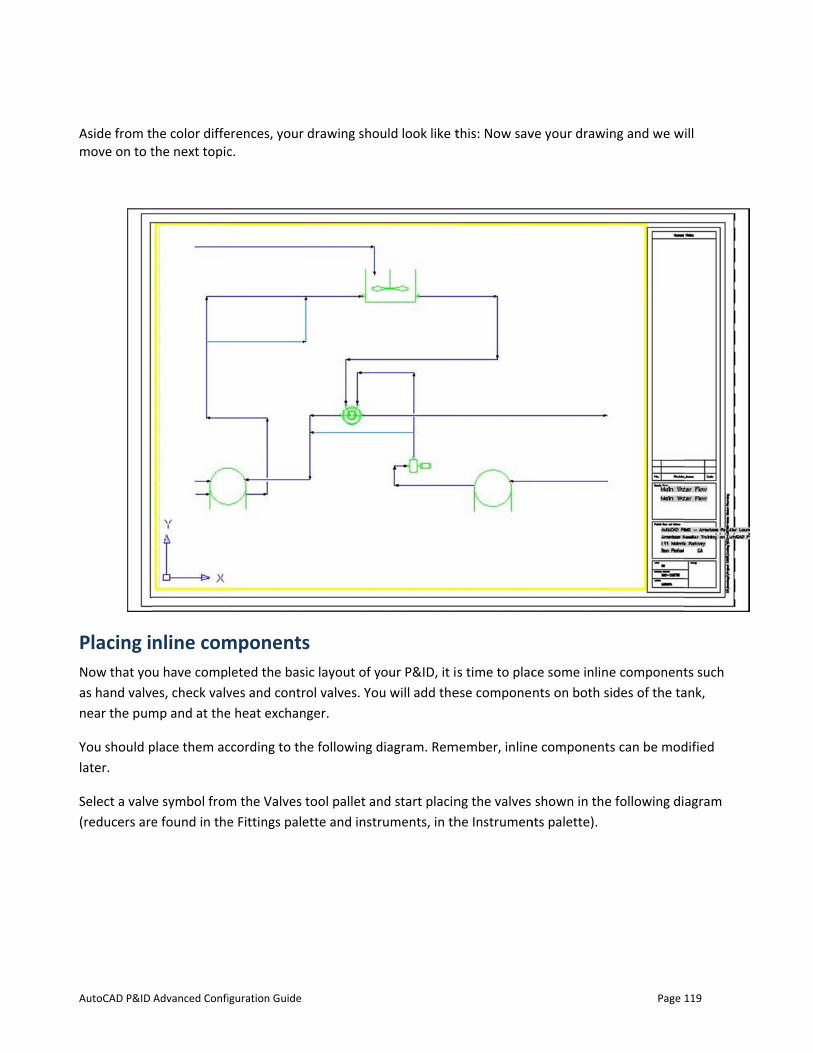
AutoCAD P&ID
Aside from tmove on to t
Placing iNow that yoas hand valvnear the pum
You should plater.
Select a valv(reducers are
Advanced Confi
he color diffethe next topic
nline comu have compes, check valv
mp and at the
place them ac
e symbol frome found in the
iguration Guide
erences, your c.
mponentsleted the basves and contre heat exchan
ccording to th
m the Valves e Fittings pale
drawing sho
s sic layout of yrol valves. Younger.
he following d
tool pallet anette and instr
uld look like t
your P&ID, it iu will add the
diagram. Rem
nd start placinruments, in th
this: Now sav
s time to placese compone
member, inline
ng the valves he Instrumen
ve your drawi
ce some inlinnts on both s
e component
shown in thents palette).
Page
ng and we w
e componentsides of the ta
ts can be mod
e following di
119
ill
ts such ank,
dified
agram
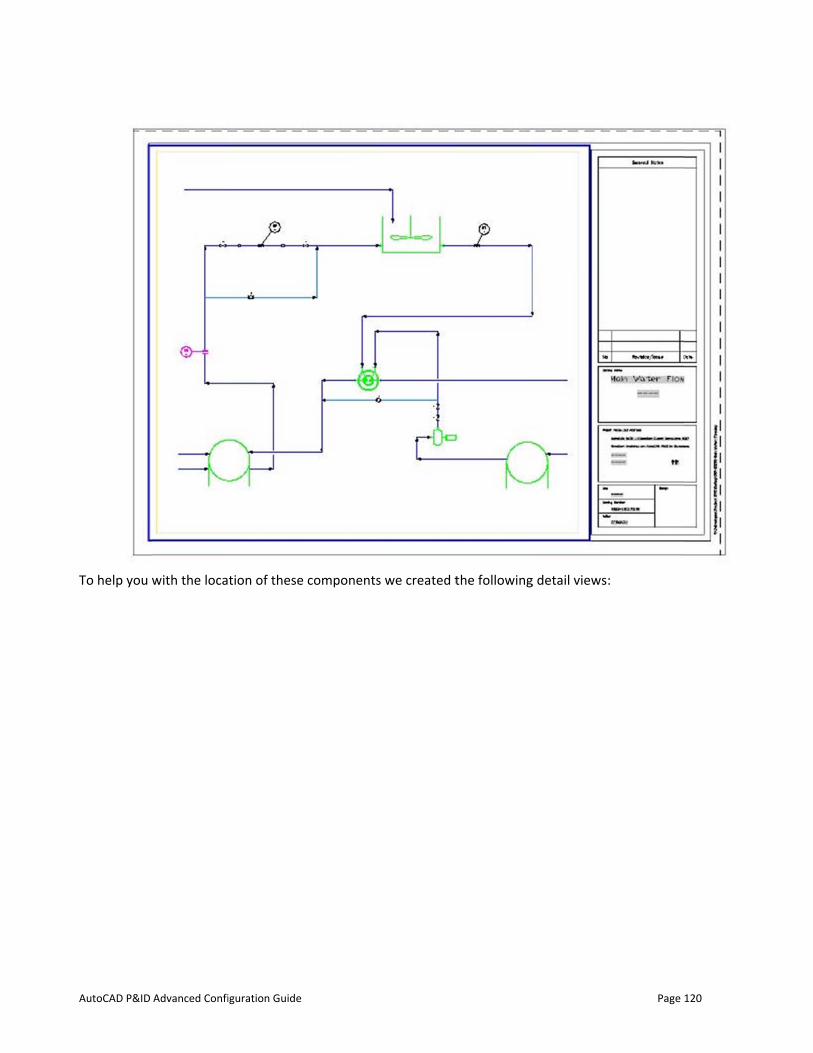
AutoCAD P&ID
To help you
Advanced Confi
with the loca
iguration Guide
tion of these componentss we created tthe followingg detail views:
Page
:
120
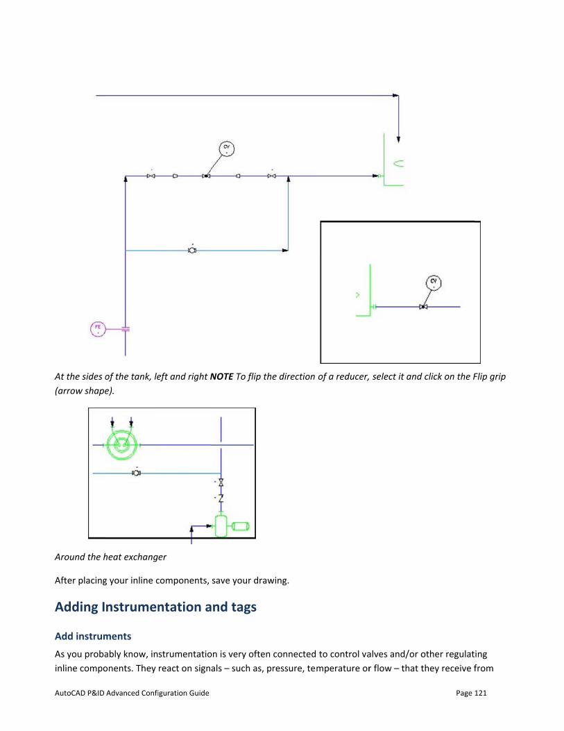
AutoCAD P&ID
At the sides o(arrow shape
Around the h
After placing
Adding I
Add instrumAs you probainline compo
Advanced Confi
of the tank, lee).
heat exchang
g your inline c
nstrumen
ments ably know, inonents. They
iguration Guide
eft and right N
er
components,
ntation a
strumentatioreact on sign
NOTE To flip
save your dra
and tags
on is very ofteals – such as,
the direction
awing.
en connected pressure, tem
of a reducer,
to control vamperature or
select it and
alves and/or or flow – that t
Page
d click on the F
other regulatthey receive f
121
Flip grip
ing from
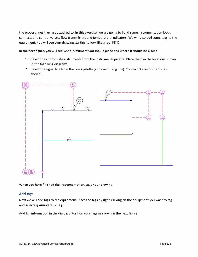
AutoCAD P&ID
the process lconnected toequipment. Y
In the next fi
1. Selein th
2. Seleshow
When you ha
Add tags Next we will and selecting
Add tag info
Advanced Confi
lines they areo control valvYou will see y
igure, you wil
ct the approphe following dct the signal l
wn.
ave finished t
add tags to tg Annotate ->
rmation in th
iguration Guide
e attached to.ves, flow tranyour drawing
ll see what in
priate instrumdiagrams. line from the
the instrumen
the equipmen> Tag.
e dialog. 3 Po
. In this exercsmitters and starting to lo
strument you
ments from th
Lines palette
ntation, save
nt. Place the t
osition your t
cise, we are gotemperature
ook like a real
u should plac
he Instrument
e (and one tub
your drawing
tags by right-c
ags as shown
oing to build e indicators. W P&ID.
e and where
ts palette. Pla
bing line). Co
g.
clicking on th
n in the next f
some instrumWe will also a
it should be p
ace them in th
nnect the ins
he equipment
figure.
Page
mentation loodd some tags
placed.
he locations s
struments, as
t you want to
122
ops s to the
shown
tag
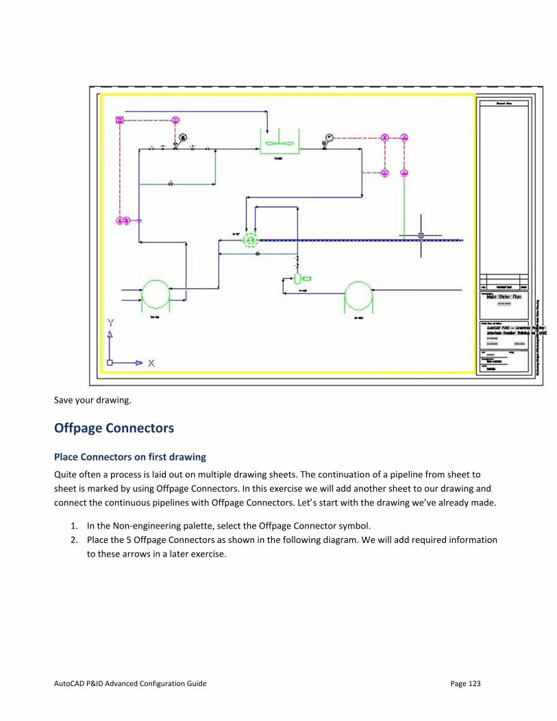
AutoCAD P&ID
Save your dr
Offpage
Place ConnQuite often asheet is marconnect the
1. In th2. Place
to th
Advanced Confi
rawing.
Connecto
ectors on fira process is laked by using continuous p
he Non-enginee the 5 Offpa
hese arrows in
iguration Guide
ors
rst drawing aid out on muOffpage Conn
pipelines with
eering palettege Connectorn a later exer
ultiple drawinnectors. In th
h Offpage Con
e, select the Ors as shown in
rcise.
ng sheets. Theis exercise we
nnectors. Let’
Offpage Connn the followin
e continuatioe will add anos start with th
nector symbong diagram. W
n of a pipelinother sheet the drawing w
ol. We will add re
Page
ne from sheeto our drawin
we’ve already
equired infor
123
t to g and made.
mation
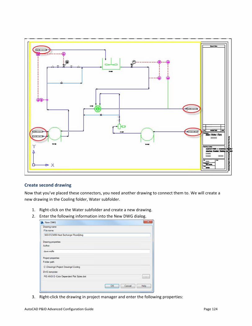
AutoCAD P&ID
Create secoNow that yonew drawing
1. Righ2. Ente
3. Righ
Advanced Confi
ond drawingu’ve placed tg in the Coolin
t-click on theer the followin
t-click the dra
iguration Guide
g hese connectng folder, Wa
e Water subfong informatio
awing in proj
tors, you needater subfolder
older and creaon into the Ne
ect manager
d another drar.
ate a new draew DWG dialo
and enter the
awing to conn
awing. og.
e following p
nect them to
roperties:
Page
. We will crea
124
ate a
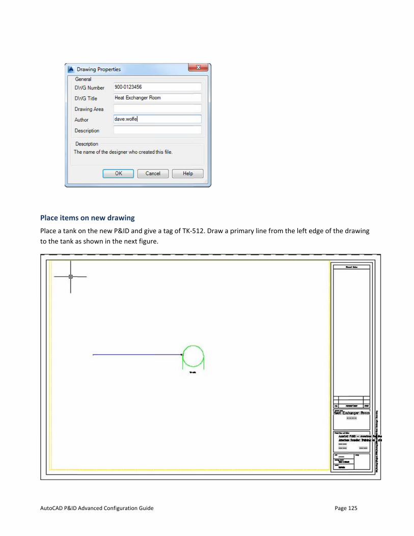
AutoCAD P&ID
Place itemsPlace a tank to the tank a
Advanced Confi
s on new draon the new P
as shown in th
iguration Guide
awing P&ID and givehe next figure
e a tag of TK-5e.
512. Draw a pprimary line from the left e
Page
edge of the d
125
rawing
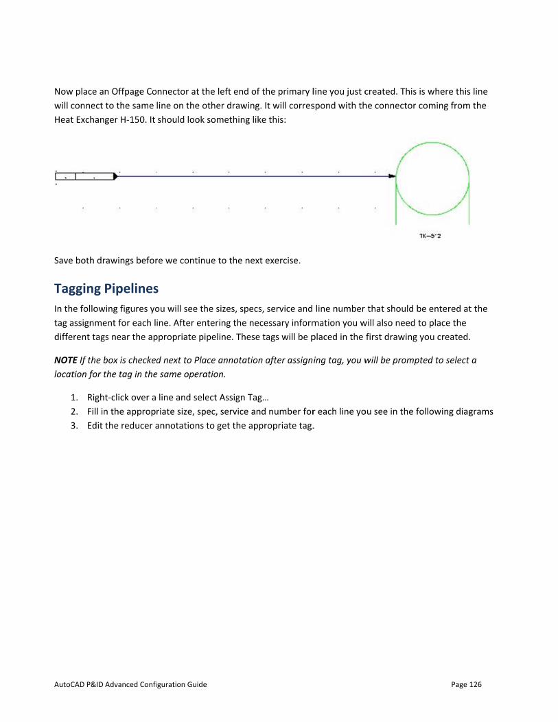
AutoCAD P&ID
Now place awill connect Heat Exchan
Save both dr
Tagging In the followtag assignmedifferent tag
NOTE If the blocation for t
1. Righ2. Fill in3. Edit
Advanced Confi
n Offpage Coto the same ger H-150. It
rawings befor
Pipelineswing figures yoent for each lgs near the ap
box is checkedthe tag in the
t-click over a n the appropthe reducer a
iguration Guide
nnector at thline on the otshould look s
re we continu
s ou will see thine. After ent
ppropriate pip
d next to Place same operat
line and seleriate size, speannotations t
he left end of ther drawing.something lik
ue to the next
e sizes, specstering the necpeline. These
ce annotationtion.
ect Assign Tagec, service anto get the app
the primary l. It will corres
ke this:
t exercise.
s, service and cessary informtags will be p
n after assign
g… d number for
propriate tag.
line you just cspond with th
line number mation you wplaced in the
ing tag, you w
r each line yo.
created. This he connector
that should bwill also need
first drawing
will be promp
ou see in the f
Page
is where thiscoming from
be entered atto place the you created.
pted to select
following diag
126
s line m the
t the
.
a
grams
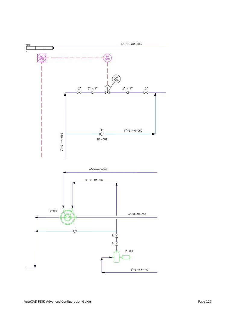
AutoCAD P&ID
Advanced Confiiguration Guide
Page 127

AutoCAD P&ID
Detacove
When you ha
Advanced Confi
ail view showier Data Mana
ave finished,
iguration Guide
ing tag locatiager.
the drawing
ions and adde
should look li
ed informatio
ike the one b
on. Descriptio
elow.
ons will be ha
Page
ndled later w
128
when we
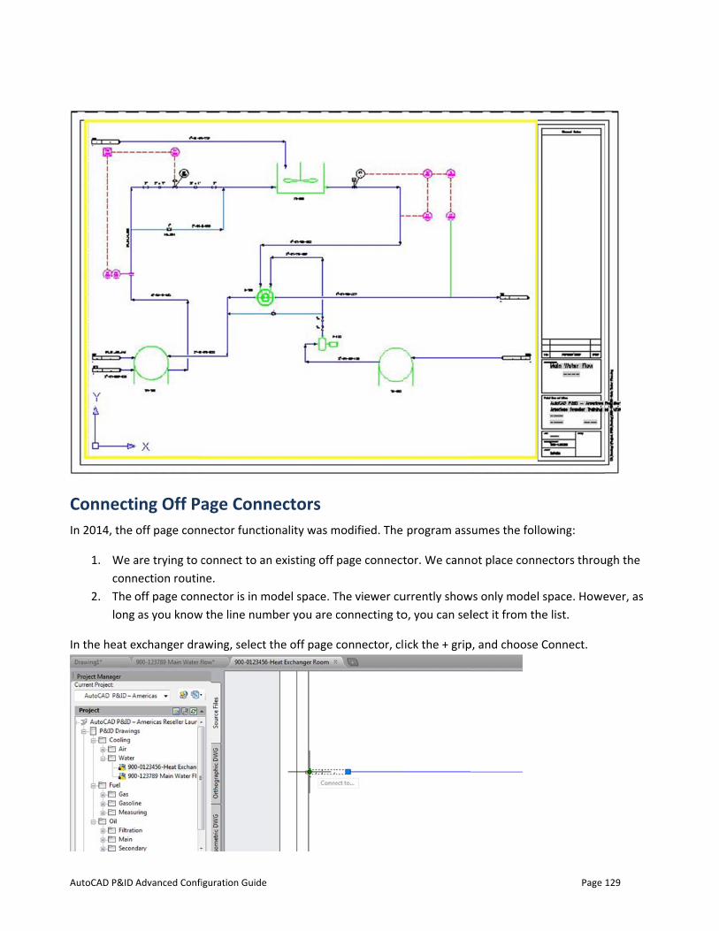
AutoCAD P&ID
ConnectIn 2014, the
1. We aconn
2. The long
In the heat e
Advanced Confi
ing Off Paoff page conn
are trying to cnection routinoff page conn as you know
exchanger dra
iguration Guide
age Connnector functio
connect to anne. nector is in m
w the line num
awing, select
nectors onality was m
n existing off
model space. Tmber you are c
the off page
modified. The
page connect
The viewer cuconnecting to
connector, cl
program ass
tor. We cann
urrently showo, you can sel
ick the + grip
sumes the foll
ot place conn
ws only modellect it from th
p, and choose
Page
lowing:
nectors throu
l space. Howehe list.
Connect.
129
ugh the
ever, as
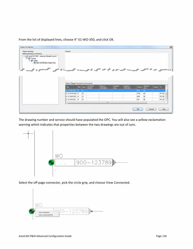
AutoCAD P&ID
From the list
The drawingwarning whi
Select the of
Advanced Confi
t of displayed
number andch indicates t
ff page conne
iguration Guide
lines, choose
service shouthat propertie
ector, pick the
e 4”-S1-WO-3
ld have popues between th
e circle grip, a
350, and click
ulated the OPhe two drawi
and choose Vi
k OK.
C. You will alsings are out o
iew Connecte
so see a yelloof sync.
ed.
Page
ow exclamatio
130
on
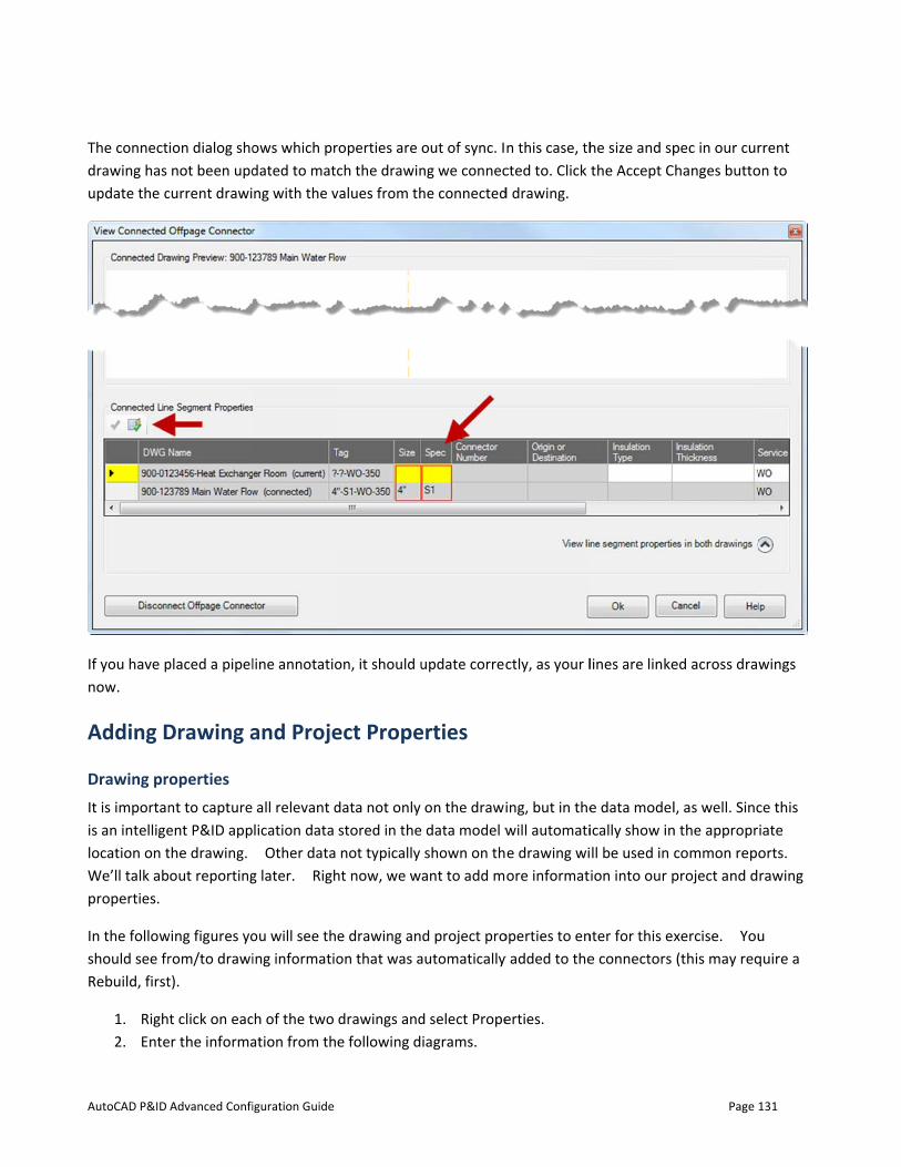
AutoCAD P&ID
The connectdrawing has update the c
If you have pnow.
Adding D
Drawing prIt is importanis an intelligelocation on tWe’ll talk abproperties.
In the followshould see frRebuild, first
1. Righ2. Ente
Advanced Confi
ion dialog shonot been upd
current drawi
placed a pipel
Drawing a
operties nt to capture ent P&ID appthe drawing. out reporting
wing figures yorom/to drawit).
t click on eacer the informa
iguration Guide
ows which prdated to matcng with the v
line annotatio
and Proje
all relevant dlication data Other data
g later. Righ
ou will see thing informatio
ch of the two ation from th
roperties are ch the drawin
values from th
on, it should u
ect Prope
data not only stored in thenot typically
ht now, we w
e drawing anon that was a
drawings ande following d
out of sync. Ing we conneche connected
update correc
erties
on the drawi data model wshown on thant to add m
d project proautomatically
d select Propeiagrams.
n this case, thcted to. Click d drawing.
ctly, as your l
ing, but in thewill automatie drawing wiore informat
operties to eny added to the
erties.
he size and spthe Accept C
lines are linke
e data modelically show inll be used in cion into our p
nter for this exe connectors
Page
pec in our curhanges butto
ed across draw
l, as well. Sincn the approprcommon repoproject and d
xercise. You(this may req
131
rrent on to
wings
ce this iate orts. rawing
u quire a
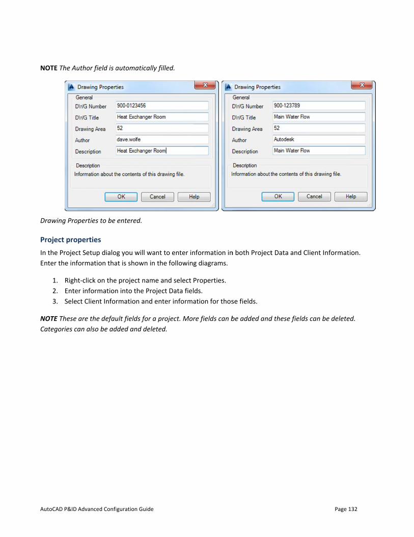
AutoCAD P&ID
NOTE The Au
Drawing Pro
Project proIn the ProjecEnter the inf
1. Righ2. Ente3. Sele
NOTE These Categories ca
Advanced Confi
uthor field is a
perties to be
perties ct Setup dialoformation tha
t-click on theer informationct Client Infor
are the defauan also be ad
iguration Guide
automatically
entered.
g you will waat is shown in
e project namn into the Prormation and e
ult fields for added and dele
y filled.
ant to enter in the following
e and select Poject Data fielenter informa
a project. Moreted.
nformation ing diagrams.
Properties. ds. ation for thos
re fields can b
n both Project
se fields.
be added and
t Data and Cli
d these fields
Page
ient Informat
can be delete
132
tion.
ed.

AutoCAD P&ID
Project Data
Client Inform
When you ar
Advanced Confi
a properties to
mation proper
re done enter
iguration Guide
o be entered.
rties to be ent
ring the infor
tered
mation, save your drawinggs.
Page 133
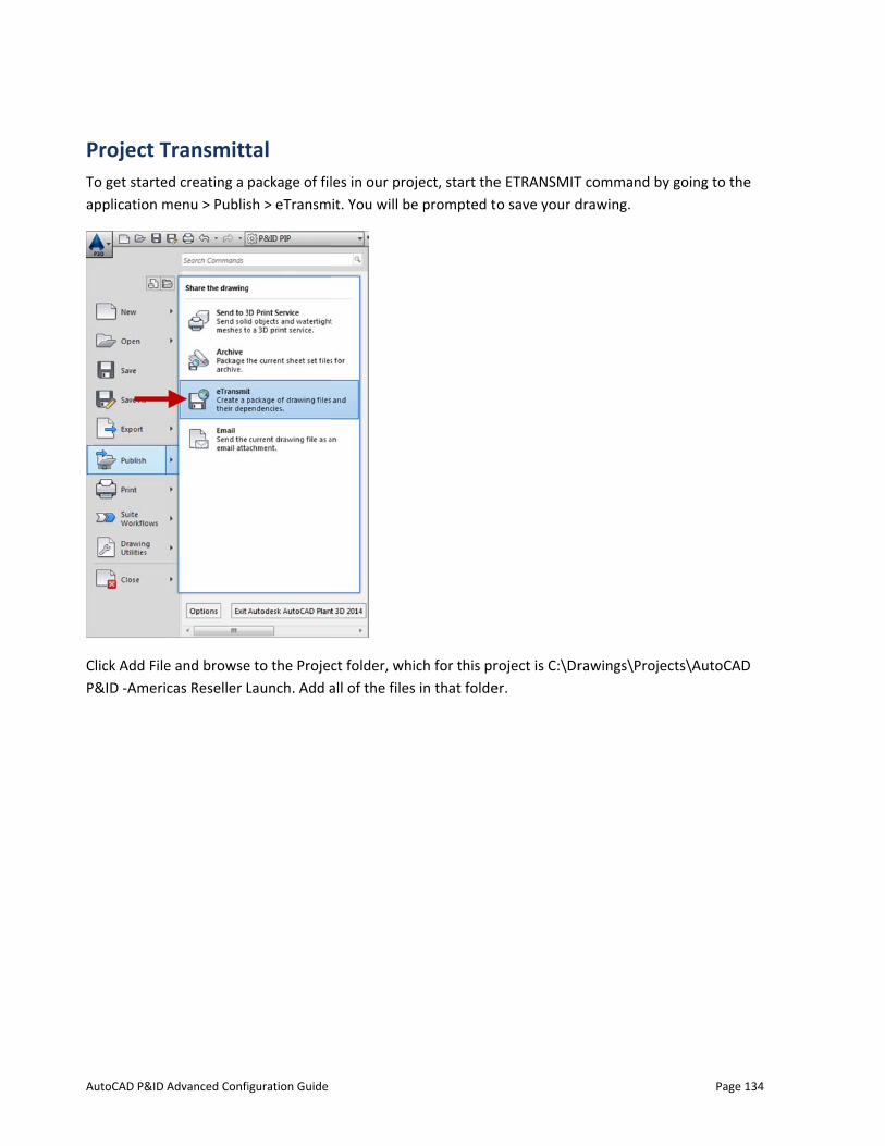
AutoCAD P&ID
Project TTo get starteapplication m
Click Add FileP&ID -Ameri
Advanced Confi
Transmitted creating a menu > Publis
e and browsecas Reseller L
iguration Guide
tal package of filsh > eTransm
e to the ProjeLaunch. Add a
les in our proit. You will be
ct folder, whiall of the files
ject, start thee prompted t
ich for this prs in that folde
e ETRANSMITo save your d
roject is C:\Drer.
T command bdrawing.
rawings\Proje
Page
y going to the
ects\AutoCAD
134
e
D
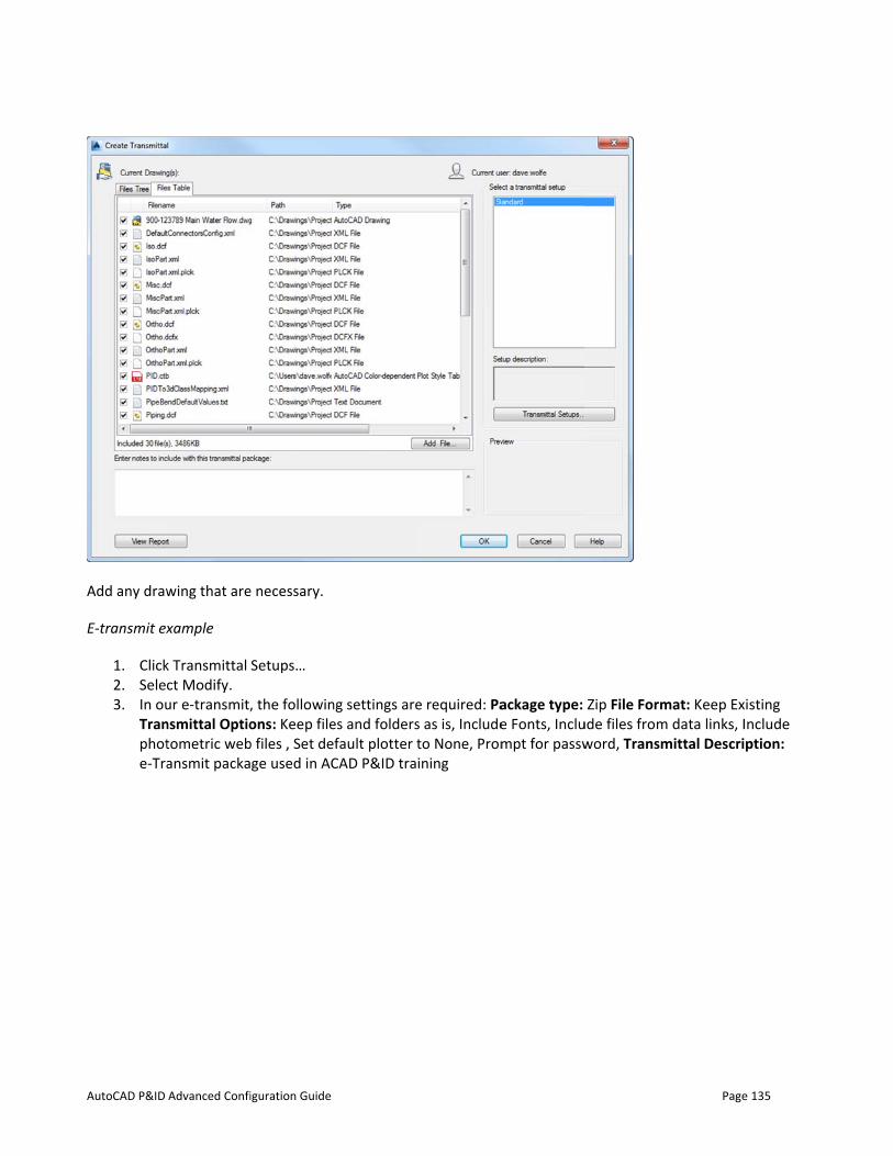
AutoCAD P&ID
Add any draw
E‐transmit ex
1. Click2. Sele3. In ou
Tranphote-Tra
Advanced Confi
wing that are
xample
k Transmittal ct Modify. ur e-transmit,nsmittal Optiotometric webansmit packa
iguration Guide
e necessary.
Setups…
, the followinons: Keep file
b files , Set dege used in AC
ng settings arees and foldersfault plotter t
CAD P&ID tra
e required: Pas as is, Includeto None, Promining
ackage type: e Fonts, Inclumpt for passw
Zip File Formude files fromword, Transm
Page
mat: Keep Exis data links, In
mittal Descrip
135
sting nclude ption:
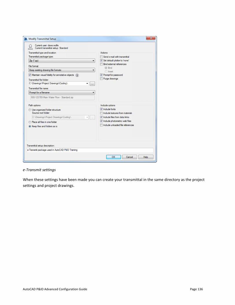
AutoCAD P&ID
e‐Transmit s
When these settings and
Advanced Confi
ettings
settings haveproject draw
iguration Guide
e been made wings.
you can create your transsmittal in the
same directo
Page
ory as the pro
136
oject
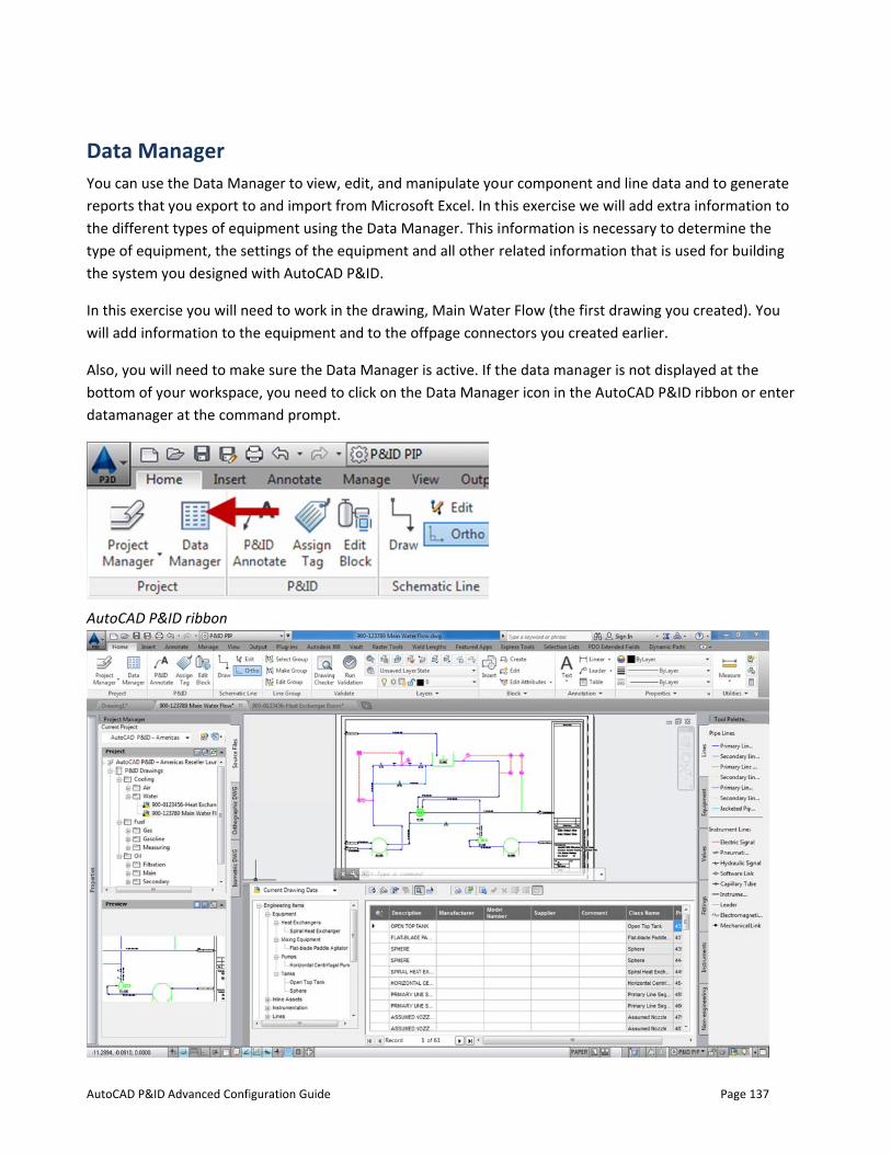
AutoCAD P&ID
Data MaYou can use reports that the differenttype of equipthe system y
In this exerciwill add info
Also, you wilbottom of yodatamanage
AutoCAD P&
Advanced Confi
anager the Data Manyou export to
t types of equpment, the seyou designed
ise you will nermation to th
ll need to maour workspacer at the comm
ID ribbon
iguration Guide
nager to viewo and import uipment usingettings of thewith AutoCA
eed to work ihe equipment
ke sure the Dce, you need tmand prompt
w, edit, and mfrom Microso
g the Data Ma equipment aD P&ID.
n the drawint and to the o
Data Managerto click on thet.
manipulate yooft Excel. In tanager. This iand all other r
g, Main Wateoffpage conne
r is active. If te Data Manag
ur componenhis exercise winformation isrelated inform
er Flow (the fectors you cre
the data manager icon in th
nt and line dawe will add exs necessary tomation that is
first drawing yeated earlier.
ager is not die AutoCAD P&
Page
ata and to genxtra informato determine ts used for bui
you created)..
splayed at th&ID ribbon o
137
nerate tion to the ilding
. You
e r enter
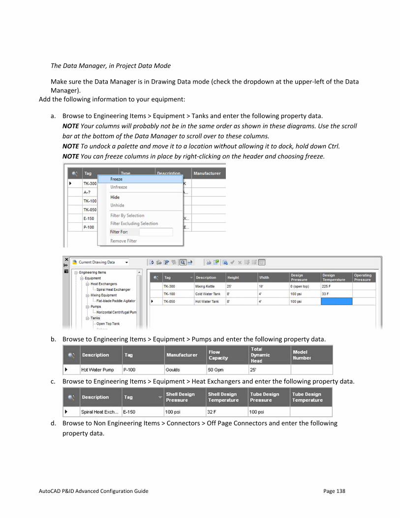
AutoCAD P&ID
The Data
Make suManage
Add the follo
a. BrowNOTbar aNOTNOT
b. Brow
c. Brow
d. Browprop
Advanced Confi
a Manager, in
re the Data Mr). owing informa
wse to EngineTE Your columat the bottom
TE To undock TE You can fre
wse to Engine
wse to Engine
wse to Non Enperty data.
iguration Guide
n Project Data
Manager is in
ation to your
eering Items >mns will probam of the Data
a palette andeeze columns
eering Items >
eering Items >
ngineering Ite
a Mode
Drawing Dat
equipment:
> Equipment >ably not be in
Manager to sd move it to ain place by ri
> Equipment >
> Equipment >
ems > Connec
ta mode (chec
> Tanks and ethe same ordscroll over to location with
ight‐clicking o
> Pumps and
> Heat Excha
ctors > Off Pa
ck the dropdo
enter the folloder as shown
these columnhout allowingon the header
enter the fol
ngers and en
age Connecto
own at the up
owing properin these diagns. g it to dock, hr and choosin
llowing prope
ter the follow
rs and enter t
Page
pper-left of th
rty data. grams. Use th
old down Ctrng freeze.
erty data.
wing property
the following
138
he Data
e scroll
rl.
y data.
g
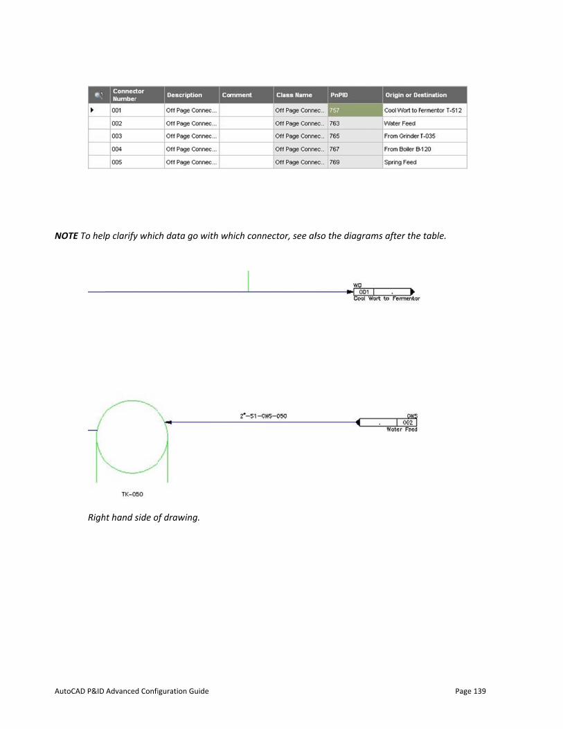
AutoCAD P&ID
NOTE To help
Righ
Advanced Confi
p clarify whic
ht hand side of
iguration Guide
ch data go wit
of drawing.
th which connnector, see allso the diagraams after the
Page
table.
139
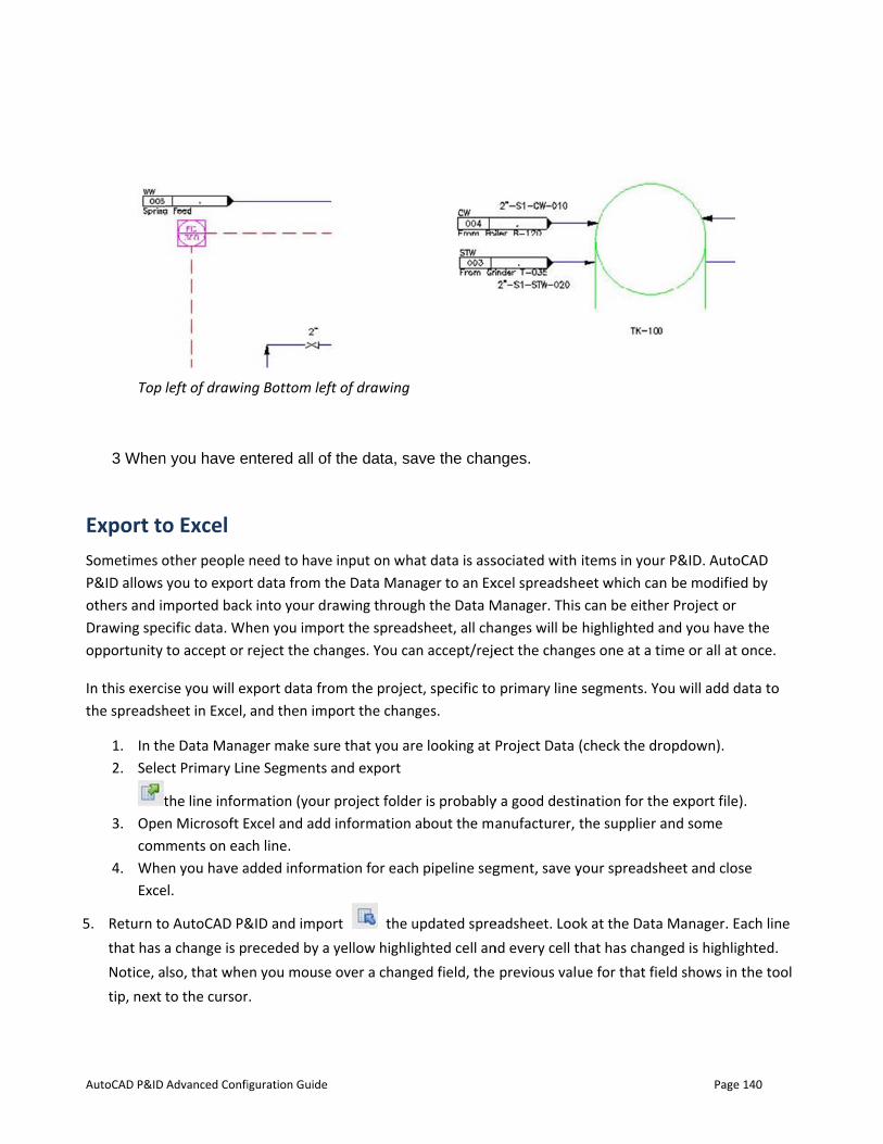
AutoCAD P&ID
Top
3 When
Export toSometimes oP&ID allows others and imDrawing speopportunity
In this exercithe spreadsh
1. In th2. Sele
t3. Ope
com4. Whe
Exce
5. Return tothat has aNotice, atip, next
Advanced Confi
left of drawin
n you have e
o Excel other people you to expor
mported backcific data. Whto accept or
ise you will exheet in Excel,
he Data Manact Primary Lin
the line inforn Microsoft Ements on eac
en you have ael.
o AutoCAD P&a change is plso, that wheto the cursor
iguration Guide
ng Bottom lef
ntered all of
need to havert data from tk into your drhen you imporeject the cha
xport data froand then imp
ager make surne Segments
mation (your Excel and addch line. added informa
&ID and imporeceded by a
en you mouse.
ft of drawing
f the data, sa
e input on whhe Data Manrawing througort the spreadanges. You ca
om the projecport the chan
re that you arand export
project folde information
ation for each
ort the uyellow highli
e over a chang
ave the chan
at data is assager to an Exgh the Data Mdsheet, all chaan accept/reje
ct, specific tonges.
re looking at P
er is probablyabout the ma
h pipeline seg
updated spreighted cell anged field, the
nges.
sociated with xcel spreadshManager. Thisanges will be ect the chang
primary line
Project Data
y a good destianufacturer,
gment, save y
eadsheet. Loond every cell t
previous valu
items in youeet which cans can be eithe
highlighted ages one at a t
segments. Yo
(check the dr
ination for ththe supplier a
your spreadsh
ok at the Datathat has chanue for that fie
Page
r P&ID. AutoCn be modifieder Project or and you haveime or all at o
ou will add da
ropdown).
e export file)and some
heet and clos
a Manager. Eaged is highligeld shows in t
140
CAD d by
e the once.
ata to
.
se
ach line ghted. the tool
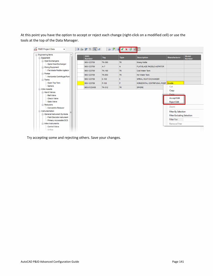
AutoCAD P&ID
At this point tools at the t
Try acce
Advanced Confi
you have thetop of the Da
pting some a
iguration Guide
e option to acta Manager.
nd rejecting o
ccept or rejec
others. Save y
ct each chang
your changes
ge (right-click
s.
on a modifie
Page
d cell) or use
141
the

AutoCAD P&ID
ReportinAs stated eacreates intelfunctions thr
In this exerci
Make sure th
The highlightprocedure is
1. Highfollo• C• D• E• I
Advanced Confi
ng rlier, some daligent drawinrough the pro
ise we will ag
hat your Data
ted list, abovs detailed in t
hlight (click onowing report tControl ValveDocument ReEquipment LiInstrument Li
iguration Guide
ata is better rngs and keepsogram interfa
gain export da
a Manager is s
e, shows the he help files.
n) Project Reptypes: e List egistry st ist
represented is the data in tace. This will s
ata, but in thi
set to Project
default repor
ports and clic
n a report ratthe drawing, ysave you a lot
s case it will b
t Reports (che
rt types. You
k on the Expo
ther than on you have acct of time coun
be formatted
eck the dropd
can also crea
ort tool. 3 Ma
a drawing. Siess to many cnting pipeline
d in a specific
down).
ate custom re
ark the check
Page
nce AutoCADcommon repoes for a line lis
report type.
eport templat
box for each
142
D P&ID orting st!
tes. This
of the
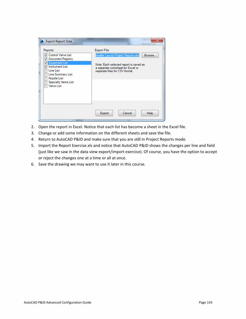
AutoCAD P&ID
2. Ope3. Chan4. Retu5. Impo
(justor re
6. Save
Advanced Confi
n the report inge or add sourn to AutoCAort the Report like we saw eject the chane the drawing
iguration Guide
in Excel. Notiome informatAD P&ID and mrt Exercise.xlsin the data vi
nges one at a g we may wan
ce that each ion on the difmake sure th
s and notice tew export/imtime or all at
nt to use it lat
list has becomfferent sheetsat you are stihat AutoCAD
mport exerciset once. ter in this cou
me a sheet ins and save thill in Project R P&ID shows e). Of course,
urse.
the Excel file
he file. Reports modethe changes , you have th
Page
e.
e. per line and fe option to a
143
field ccept

AutoCAD P&ID Advanced Configuration Guide Page 144
Appendix B Glossary of P&ID Terms
Glossary Term Definition Alarm A device or function that signals the existence of an abnormal condition by means
of an audible or visible discrete change, or both, intended to attract attention. Assignable A term applied to a feature permitting the channeling (or directing) of a signal
from one device to another without the need for switching, patching, or re-wiring.
Auto-Manual Station Synonym for control station. Balloon Synonym for bubble. Behind the Panel A term referring to devices that are not accessible for the operator’s normal use,
as opposed to devices designated as local or front-of-panel‐mounted. In a very broad sense, “behind the panel” is equivalent to “not normally accessible to the operator.”
Binary A term applied to a signal or device that has only two discrete positions or states. When used in its simplest form, as in “binary signal” (as opposed to “analog signal”), the term denotes an “on-off” or “high-low” state, i.e., one which does not represent continuously varying quantities.
Bubble The circular symbol used to denote and identify the purpose of an instrument or function. It may contain a tag number. Synonym for balloon.
Computing Device A device or function that performs one or more calculations or logic operations, or both, and transmits one or more resultant output signals. A computing device is sometimes called a computing relay.
Configurable A term applied to a device or system whose functional characteristics can be selected or rearranged through programming or other methods. The concept usually excludes re-wiring as a means of altering the configuration.
Controller A device having an output that changes to regulate a controlled variable in a specified manner. A controller may be a self-contained analog or digital instrument, or it may be the equivalent of such an instrument in a shared-control system. An automatic controller varies its output automatically in response to a direct or indirect input of a measured process variable. A manual controller is a manual loading station, and its output is not dependent on a measured process variable but can be varied only by manual adjustment. A controller may be integral with other functional elements of a control loop.
Control Station A manual loading station that also provides switching between manual and automatic control modes of a control loop. It is also known as an auto‐manual station. In addition, the operator interface of a distributed control system may be regarded as a control station.
Control Valve A device, other than a common, hand-actuated ON-OFF valve or self- actuated check valve that directly manipulates the flow of one or more fluid process streams. In general, use of the designation “hand control valve” is limited to hand-actuated valves that (1) are used for process throttling, or
Converter A device that receives information in one form of an instrument signal and transmits an output signal in another form. An instrument that changes a sensor’s
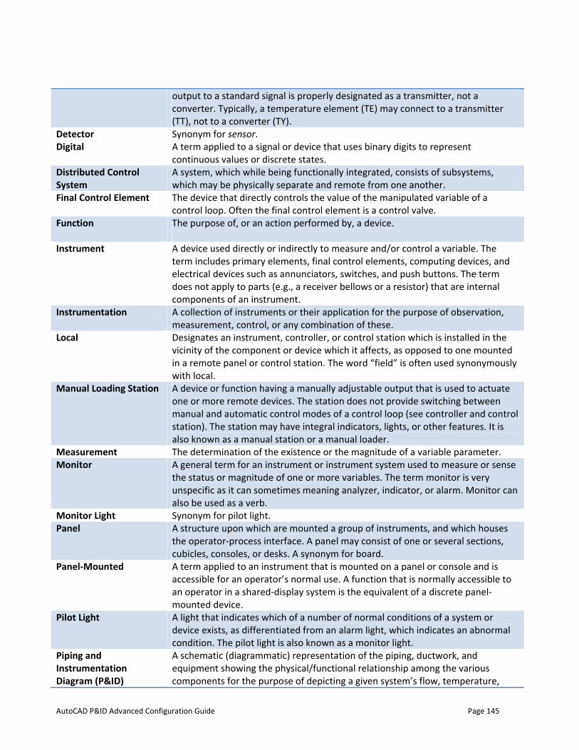
AutoCAD P&ID Advanced Configuration Guide Page 145
output to a standard signal is properly designated as a transmitter, not a converter. Typically, a temperature element (TE) may connect to a transmitter (TT), not to a converter (TY).
Detector Digital
Synonym for sensor. A term applied to a signal or device that uses binary digits to represent continuous values or discrete states.
Distributed Control System
A system, which while being functionally integrated, consists of subsystems, which may be physically separate and remote from one another.
Final Control Element
The device that directly controls the value of the manipulated variable of a control loop. Often the final control element is a control valve.
Function
The purpose of, or an action performed by, a device.
Instrument
A device used directly or indirectly to measure and/or control a variable. The term includes primary elements, final control elements, computing devices, and electrical devices such as annunciators, switches, and push buttons. The term does not apply to parts (e.g., a receiver bellows or a resistor) that are internal components of an instrument.
Instrumentation
A collection of instruments or their application for the purpose of observation, measurement, control, or any combination of these.
Local
Designates an instrument, controller, or control station which is installed in the vicinity of the component or device which it affects, as opposed to one mounted in a remote panel or control station. The word “field” is often used synonymously with local.
Manual Loading Station
A device or function having a manually adjustable output that is used to actuate one or more remote devices. The station does not provide switching between manual and automatic control modes of a control loop (see controller and control station). The station may have integral indicators, lights, or other features. It is also known as a manual station or a manual loader.
Measurement The determination of the existence or the magnitude of a variable parameter. Monitor A general term for an instrument or instrument system used to measure or sense
the status or magnitude of one or more variables. The term monitor is very unspecific as it can sometimes meaning analyzer, indicator, or alarm. Monitor can also be used as a verb.
Monitor Light Synonym for pilot light. Panel A structure upon which are mounted a group of instruments, and which houses
the operator-process interface. A panel may consist of one or several sections, cubicles, consoles, or desks. A synonym for board.
Panel-Mounted A term applied to an instrument that is mounted on a panel or console and is accessible for an operator’s normal use. A function that is normally accessible to an operator in a shared-display system is the equivalent of a discrete panel-mounted device.
Pilot Light A light that indicates which of a number of normal conditions of a system or device exists, as differentiated from an alarm light, which indicates an abnormal condition. The pilot light is also known as a monitor light.
Piping and Instrumentation Diagram (P&ID)
A schematic (diagrammatic) representation of the piping, ductwork, and equipment showing the physical/functional relationship among the various components for the purpose of depicting a given system’s flow, temperature,
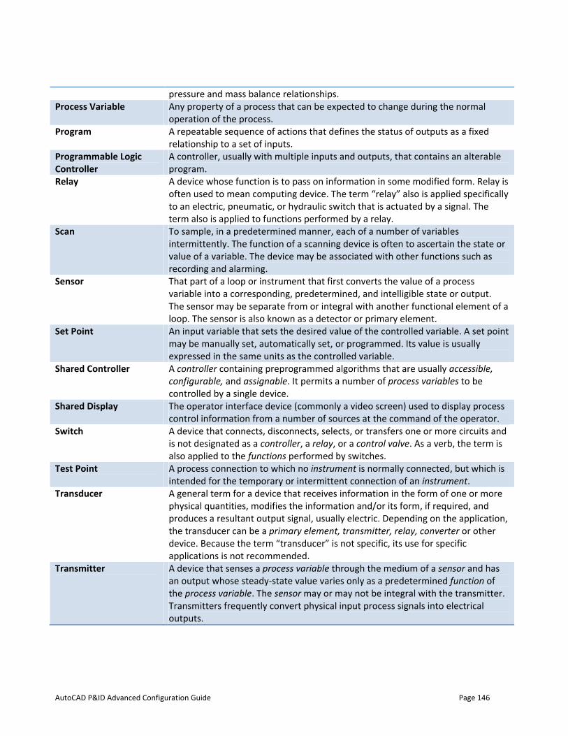
AutoCAD P&ID Advanced Configuration Guide Page 146
pressure and mass balance relationships. Process Variable Any property of a process that can be expected to change during the normal
operation of the process. Program A repeatable sequence of actions that defines the status of outputs as a fixed
relationship to a set of inputs. Programmable Logic Controller
A controller, usually with multiple inputs and outputs, that contains an alterable program.
Relay A device whose function is to pass on information in some modified form. Relay is often used to mean computing device. The term “relay” also is applied specifically to an electric, pneumatic, or hydraulic switch that is actuated by a signal. The term also is applied to functions performed by a relay.
Scan To sample, in a predetermined manner, each of a number of variables intermittently. The function of a scanning device is often to ascertain the state or value of a variable. The device may be associated with other functions such as recording and alarming.
Sensor That part of a loop or instrument that first converts the value of a process variable into a corresponding, predetermined, and intelligible state or output. The sensor may be separate from or integral with another functional element of a loop. The sensor is also known as a detector or primary element.
Set Point An input variable that sets the desired value of the controlled variable. A set point may be manually set, automatically set, or programmed. Its value is usually expressed in the same units as the controlled variable.
Shared Controller
A controller containing preprogrammed algorithms that are usually accessible, configurable, and assignable. It permits a number of process variables to be controlled by a single device.
Shared Display The operator interface device (commonly a video screen) used to display process control information from a number of sources at the command of the operator.
Switch
A device that connects, disconnects, selects, or transfers one or more circuits and is not designated as a controller, a relay, or a control valve. As a verb, the term is also applied to the functions performed by switches.
Test Point A process connection to which no instrument is normally connected, but which is intended for the temporary or intermittent connection of an instrument.
Transducer
A general term for a device that receives information in the form of one or more physical quantities, modifies the information and/or its form, if required, and produces a resultant output signal, usually electric. Depending on the application, the transducer can be a primary element, transmitter, relay, converter or other device. Because the term “transducer” is not specific, its use for specific applications is not recommended.
Transmitter
A device that senses a process variable through the medium of a sensor and has an output whose steady-state value varies only as a predetermined function of the process variable. The sensor may or may not be integral with the transmitter. Transmitters frequently convert physical input process signals into electrical outputs.

AutoCAD P&ID Advanced Configuration Guide Page 147
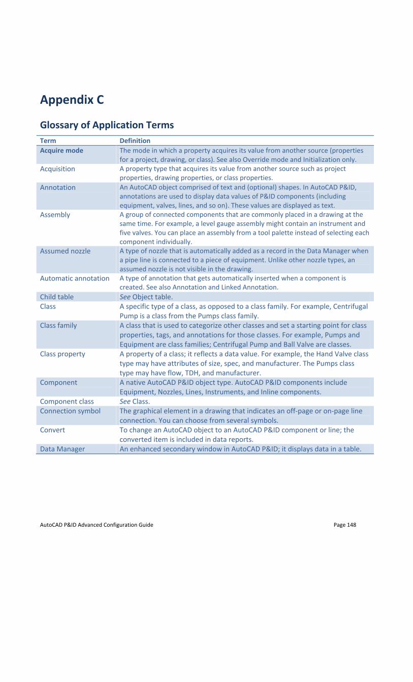
AutoCAD P&ID Advanced Configuration Guide Page 148
Appendix C
Glossary of Application Terms Term Definition Acquire mode The mode in which a property acquires its value from another source (properties
for a project, drawing, or class). See also Override mode and Initialization only. Acquisition
A property type that acquires its value from another source such as project properties, drawing properties, or class properties.
Annotation
An AutoCAD object comprised of text and (optional) shapes. In AutoCAD P&ID, annotations are used to display data values of P&ID components (including equipment, valves, lines, and so on). These values are displayed as text.
Assembly
A group of connected components that are commonly placed in a drawing at the same time. For example, a level gauge assembly might contain an instrument and five valves. You can place an assembly from a tool palette instead of selecting each component individually.
Assumed nozzle A type of nozzle that is automatically added as a record in the Data Manager when a pipe line is connected to a piece of equipment. Unlike other nozzle types, an assumed nozzle is not visible in the drawing.
Automatic annotation
A type of annotation that gets automatically inserted when a component is created. See also Annotation and Linked Annotation.
Child table See Object table. Class
A specific type of a class, as opposed to a class family. For example, Centrifugal Pump is a class from the Pumps class family.
Class family A class that is used to categorize other classes and set a starting point for class properties, tags, and annotations for those classes. For example, Pumps and Equipment are class families; Centrifugal Pump and Ball Valve are classes.
Class property
A property of a class; it reflects a data value. For example, the Hand Valve class type may have attributes of size, spec, and manufacturer. The Pumps class type may have flow, TDH, and manufacturer.
Component
A native AutoCAD P&ID object type. AutoCAD P&ID components include Equipment, Nozzles, Lines, Instruments, and Inline components.
Component class See Class. Connection symbol The graphical element in a drawing that indicates an off-page or on-page line
connection. You can choose from several symbols. Convert To change an AutoCAD object to an AutoCAD P&ID component or line; the
converted item is included in data reports. Data Manager An enhanced secondary window in AutoCAD P&ID; it displays data in a table.
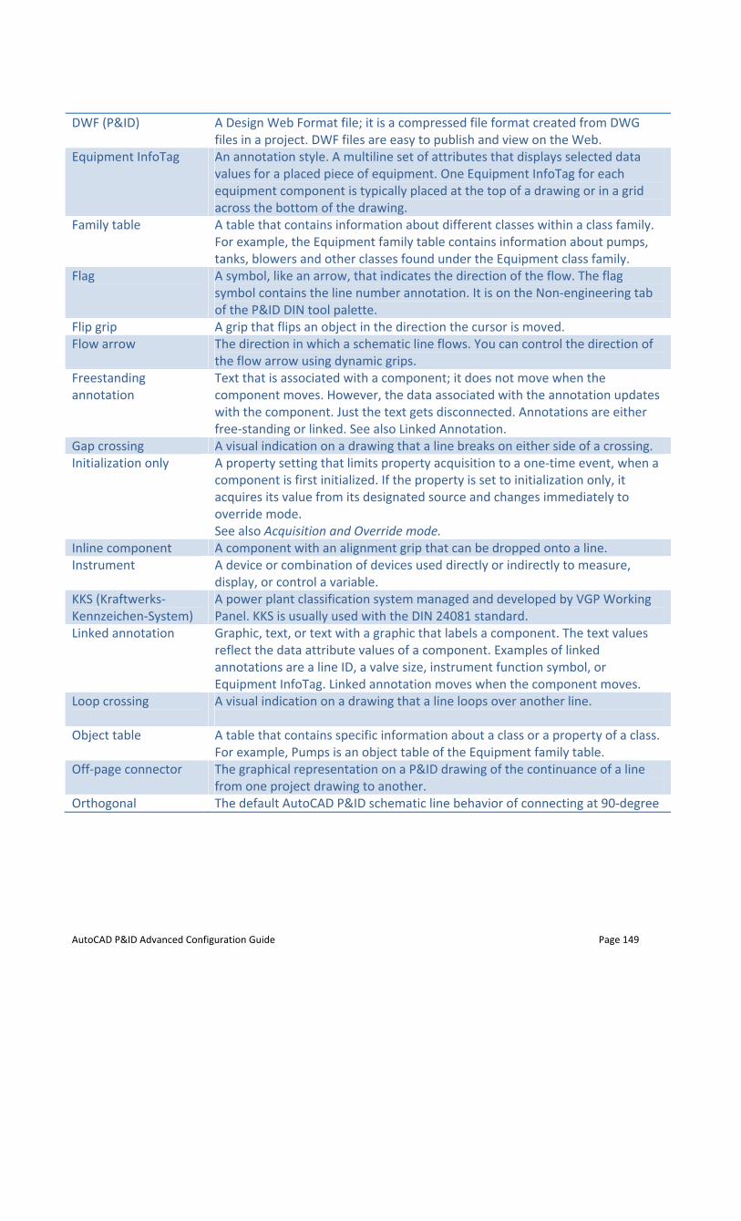
AutoCAD P&ID Advanced Configuration Guide Page 149
DWF (P&ID)
A Design Web Format file; it is a compressed file format created from DWG files in a project. DWF files are easy to publish and view on the Web.
Equipment InfoTag An annotation style. A multiline set of attributes that displays selected data values for a placed piece of equipment. One Equipment InfoTag for each equipment component is typically placed at the top of a drawing or in a grid across the bottom of the drawing.
Family table A table that contains information about different classes within a class family. For example, the Equipment family table contains information about pumps, tanks, blowers and other classes found under the Equipment class family.
Flag
A symbol, like an arrow, that indicates the direction of the flow. The flag symbol contains the line number annotation. It is on the Non-engineering tab of the P&ID DIN tool palette.
Flip grip A grip that flips an object in the direction the cursor is moved. Flow arrow The direction in which a schematic line flows. You can control the direction of
the flow arrow using dynamic grips. Freestanding annotation
Text that is associated with a component; it does not move when the component moves. However, the data associated with the annotation updates with the component. Just the text gets disconnected. Annotations are either free-standing or linked. See also Linked Annotation.
Gap crossing A visual indication on a drawing that a line breaks on either side of a crossing.Initialization only
A property setting that limits property acquisition to a one-time event, when a component is first initialized. If the property is set to initialization only, it acquires its value from its designated source and changes immediately to override mode. See also Acquisition and Override mode.
Inline component A component with an alignment grip that can be dropped onto a line. Instrument
A device or combination of devices used directly or indirectly to measure, display, or control a variable.
KKS (Kraftwerks-Kennzeichen-System)
A power plant classification system managed and developed by VGP Working Panel. KKS is usually used with the DIN 24081 standard.
Linked annotation
Graphic, text, or text with a graphic that labels a component. The text values reflect the data attribute values of a component. Examples of linked annotations are a line ID, a valve size, instrument function symbol, or Equipment InfoTag. Linked annotation moves when the component moves.
Loop crossing
A visual indication on a drawing that a line loops over another line.
Object table
A table that contains specific information about a class or a property of a class. For example, Pumps is an object table of the Equipment family table.
Off-page connector The graphical representation on a P&ID drawing of the continuance of a line from one project drawing to another.
Orthogonal The default AutoCAD P&ID schematic line behavior of connecting at 90-degree
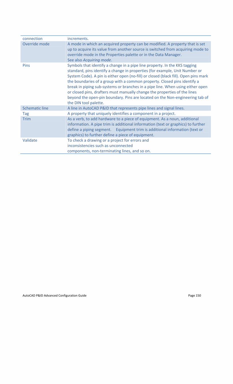
AutoCAD P&ID Advanced Configuration Guide Page 150
connection increments. Override mode
A mode in which an acquired property can be modified. A property that is set up to acquire its value from another source is switched from acquiring mode to override mode in the Properties palette or in the Data Manager. See also Acquiring mode.
Pins
Symbols that identify a change in a pipe line property. In the KKS tagging standard, pins identify a change in properties (for example, Unit Number or System Code). A pin is either open (no-fill) or closed (black fill). Open pins mark the boundaries of a group with a common property. Closed pins identify a break in piping sub-systems or branches in a pipe line. When using either open or closed pins, drafters must manually change the properties of the lines beyond the open-pin boundary. Pins are located on the Non-engineering tab of the DIN tool palette.
Schematic line A line in AutoCAD P&ID that represents pipe lines and signal lines. Tag A property that uniquely identifies a component in a project. Trim
As a verb, to add hardware to a piece of equipment. As a noun, additional information. A pipe trim is additional information (text or graphics) to further define a piping segment. Equipment trim is additional information (text or graphics) to further define a piece of equipment.
Validate
To check a drawing or a project for errors andinconsistencies such as unconnected components, non-terminating lines, and so on.


![Configuring AutoCAD Plant 3D IsometricsConfiguring AutoCAD Plant 3D Isometrics Bernd Gerstenberger – Autodesk [Munich, Germany] PD6442-L How to use the isometric configuration files](https://img.pdfslide.us/doc/110x75/5a9262c57f8b9a9c5b8b85a4/configuring-autocad-plant-3d-isometricsconfiguring-autocad-plant-3d-isometrics-bernd.jpg)