ST3400 TAWS/RMI With Traffic Capability
Installation Manual Document No. 82002-IM
Revision K 02/06/14
SANDEL AVIONICS
2401 DOGWOOD WAY VISTA, CA 92081
PHONE (760) 727-4900 FAX (760) 727-4899
WEBSITE WWW.SANDEL.COM EMAIL [email protected]

ST3400 INSTALLATION MANUAL 82002-IM-K 1-2
Revision History
Rev Date Comments K 02/06/14 Incorporated AR1356
Section 1: Approval page deleted. Section 1.1.2 added for MOD-B units. Section 3.8: Typo corrected. Section 4.8: Typos corrected. Section 8.4: Note added. Section 9: List of effective drawings updated to reflect revisions to sheets 6 & 23. Section 10.1: Updated for Garmin GTN-6XX/7XX equipment selections. 82002-10-3: Audio relay orientation corrected. 82002-10-5: Pin corrections. Notes updated. 82002-10-6: Updated to show additional grounds. 82002-10-7: Pin corrections. 82002-10-23: New drawing for Garmin GTN-6XX/7XX added.
J1 09/01/04 Incorporated A/R 740 Added error message list.
J 08/05/04 Incorporated A/R 717 Added information about Mod-A; Speaker Audio Added Airdata AZ-648 Interface
H2 04/15/04 Incorporated A/R 697 Changed installation drawings list of effective pages for audio enable relay
H1 03/17/04 Incorporated A/R 690 Added Airdata AZ-600 Interface
H 02/18/04 Incorporated A/R 675 Removed #2 Radar Altimeter input Removed #2 Analog Airdata input Added FreeFlight 1201 WAAS GPS Added Decision Height Input for Radar Altimeter Added Altitude Callouts from radar altimeter Added Back Course Input from HSI Added CIC8800M & Penny & Giles D60286 Updated pin info on P3-8 selectable discrete out Updated P1, P2, & P3 Pinouts Updated Flap XYZ Input on Dwg 19 Added Flap, Glideslope Annunciators and Override Input Added Traffic Interface

82002-IM-K ST3400 INSTALLATION MANUAL 1-3
Updated King Air STC
G1 10/17/03 Incorporated A/R 661 Added GPS interface King KLN900. Trimble 2000/3000/2101 and UPS GX Series Added Airdata Collins ADC 80 Manchester Buss Interface, Added Airdata Collins ADC85 Added Windshield Wiper Discrete Input
G 8/04/03 Incorporated A/R 638 Corrected Part Number of ST3400 Class B Gray Added GPS interface Trimble 2101 I/O. Added Airdata IS&S ADDU Added separate TCAS Inhibit Output Added Configuration Module Description
F 4/15/03 Incorporated A/R 626 Note about C92 GPWS systems HDG added to Req’d equip list. Note added in GEAR section about fixed-gear aircraft Note on flaps in ‘takeoff’ configuration Added GPS interface King KLN94 Added Airdata Collins ADC82 (), Honeywell AM-250 & AZ-810 Added OAT RS232 Interface Added Flap XYZ Interface Corrected missing ‘x’ in class-A configuration chart Note about discrete inputs in signal characteristics table Corrected various typographical errors
ST3400 INSTALLATION MANUAL 82002-IM-K 1-4
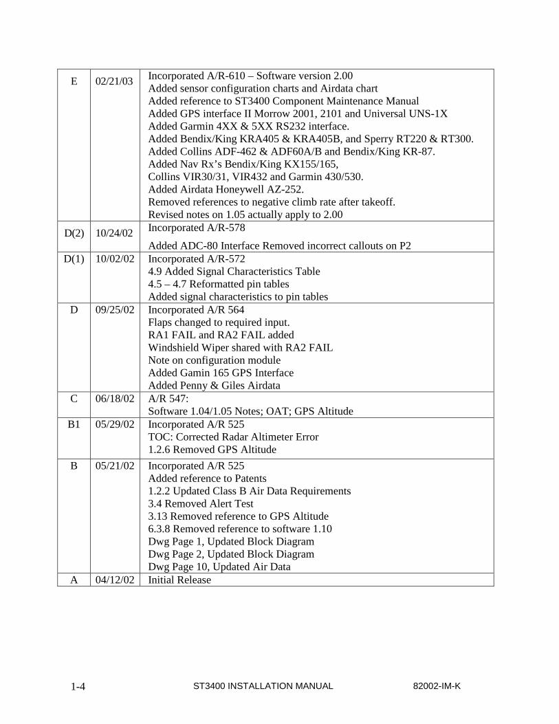
E 02/21/03 Incorporated A/R-610 – Software version 2.00 Added sensor configuration charts and Airdata chart Added reference to ST3400 Component Maintenance Manual Added GPS interface II Morrow 2001, 2101 and Universal UNS-1X Added Garmin 4XX & 5XX RS232 interface. Added Bendix/King KRA405 & KRA405B, and Sperry RT220 & RT300. Added Collins ADF-462 & ADF60A/B and Bendix/King KR-87. Added Nav Rx’s Bendix/King KX155/165, Collins VIR30/31, VIR432 and Garmin 430/530. Added Airdata Honeywell AZ-252. Removed references to negative climb rate after takeoff. Revised notes on 1.05 actually apply to 2.00
D(2) 10/24/02 Incorporated A/R-578
Added ADC-80 Interface Removed incorrect callouts on P2 D(1) 10/02/02 Incorporated A/R-572
4.9 Added Signal Characteristics Table 4.5 – 4.7 Reformatted pin tables Added signal characteristics to pin tables
D 09/25/02 Incorporated A/R 564 Flaps changed to required input. RA1 FAIL and RA2 FAIL added Windshield Wiper shared with RA2 FAIL Note on configuration module Added Gamin 165 GPS Interface Added Penny & Giles Airdata
C 06/18/02 A/R 547: Software 1.04/1.05 Notes; OAT; GPS Altitude
B1 05/29/02 Incorporated A/R 525 TOC: Corrected Radar Altimeter Error 1.2.6 Removed GPS Altitude
B 05/21/02 Incorporated A/R 525 Added reference to Patents 1.2.2 Updated Class B Air Data Requirements 3.4 Removed Alert Test 3.13 Removed reference to GPS Altitude 6.3.8 Removed reference to software 1.10 Dwg Page 1, Updated Block Diagram Dwg Page 2, Updated Block Diagram Dwg Page 10, Updated Air Data
A 04/12/02 Initial Release
82002-IM-K ST3400 INSTALLATION MANUAL 1-5
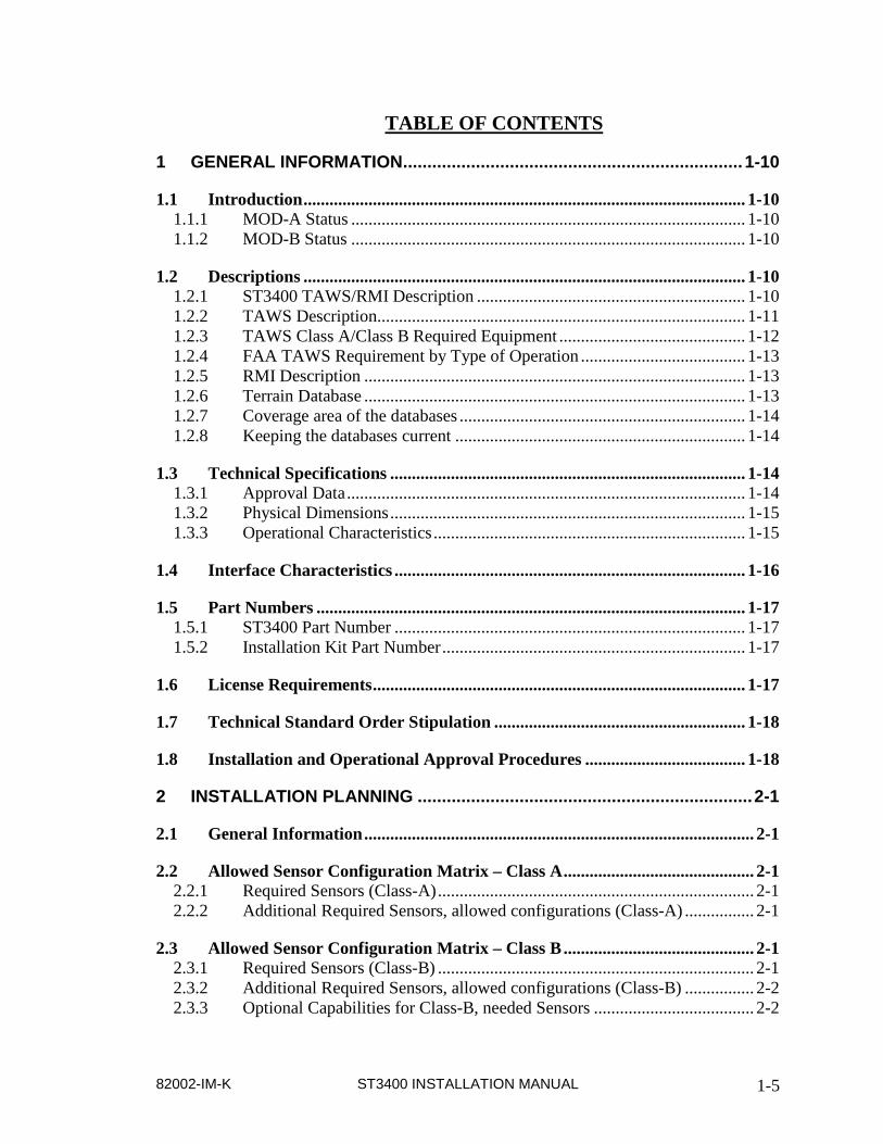
TABLE OF CONTENTS
1 GENERAL INFORMATION ...................................................................... 1-10
1.1 Introduction ...................................................................................................... 1-10 1.1.1 MOD-A Status ........................................................................................... 1-10 1.1.2 MOD-B Status ........................................................................................... 1-10
1.2 Descriptions ...................................................................................................... 1-10 1.2.1 ST3400 TAWS/RMI Description .............................................................. 1-10 1.2.2 TAWS Description..................................................................................... 1-11 1.2.3 TAWS Class A/Class B Required Equipment ........................................... 1-12 1.2.4 FAA TAWS Requirement by Type of Operation ...................................... 1-13 1.2.5 RMI Description ........................................................................................ 1-13 1.2.6 Terrain Database ........................................................................................ 1-13 1.2.7 Coverage area of the databases .................................................................. 1-14 1.2.8 Keeping the databases current ................................................................... 1-14
1.3 Technical Specifications .................................................................................. 1-14 1.3.1 Approval Data ............................................................................................ 1-14 1.3.2 Physical Dimensions .................................................................................. 1-15 1.3.3 Operational Characteristics ........................................................................ 1-15
1.4 Interface Characteristics ................................................................................. 1-16
1.5 Part Numbers ................................................................................................... 1-17 1.5.1 ST3400 Part Number ................................................................................. 1-17 1.5.2 Installation Kit Part Number ...................................................................... 1-17
1.6 License Requirements ...................................................................................... 1-17
1.7 Technical Standard Order Stipulation .......................................................... 1-18
1.8 Installation and Operational Approval Procedures ..................................... 1-18
2 INSTALLATION PLANNING ..................................................................... 2-1
2.1 General Information .......................................................................................... 2-1
2.2 Allowed Sensor Configuration Matrix – Class A ............................................ 2-1 2.2.1 Required Sensors (Class-A) ......................................................................... 2-1 2.2.2 Additional Required Sensors, allowed configurations (Class-A) ................ 2-1
2.3 Allowed Sensor Configuration Matrix – Class B ............................................ 2-1 2.3.1 Required Sensors (Class-B) ......................................................................... 2-1 2.3.2 Additional Required Sensors, allowed configurations (Class-B) ................ 2-2 2.3.3 Optional Capabilities for Class-B, needed Sensors ..................................... 2-2

ST3400 INSTALLATION MANUAL 82002-IM-K 1-6
2.4 Altitude Sources and Airdata ........................................................................... 2-2 2.4.1 Airdata System Block Diagram ................................................................... 2-3 2.4.2 OAT Requirements ...................................................................................... 2-4
2.5 Pre-installation Planning ................................................................................... 2-4
2.6 Post Installation Procedures ............................................................................. 2-5
3 INTERFACE FUNCTIONS ......................................................................... 3-1
3.1 Dual Inputs ......................................................................................................... 3-1
3.2 Power ................................................................................................................... 3-1
3.3 External Annunciators ...................................................................................... 3-1
3.4 Flaps .................................................................................................................... 3-2
3.5 Landing Gear ..................................................................................................... 3-2
3.6 Autopilot ............................................................................................................. 3-2
3.7 Audio Panel......................................................................................................... 3-3
3.8 GPS/FMS ............................................................................................................ 3-3
3.9 Radar Altimeter ................................................................................................. 3-3
3.10 Heading System .................................................................................................. 3-4
3.11 ADF Receiver ..................................................................................................... 3-4
3.12 NAV Receiver and Glideslope........................................................................... 3-5
3.13 Air Data Computer ............................................................................................ 3-5
3.14 OAT Probe .......................................................................................................... 3-5
3.15 Traffic.................................................................................................................. 3-6
3.16 ST3400 Interlink ................................................................................................ 3-6
3.17 Uploading Equipment ........................................................................................ 3-6
3.18 Display Dimming ................................................................................................ 3-6
3.19 Windshield Wipers............................................................................................. 3-6
4 INSTALLATION ......................................................................................... 4-1
4.1 Unpacking and Inspecting Equipment ............................................................ 4-1
82002-IM-K ST3400 INSTALLATION MANUAL 1-7
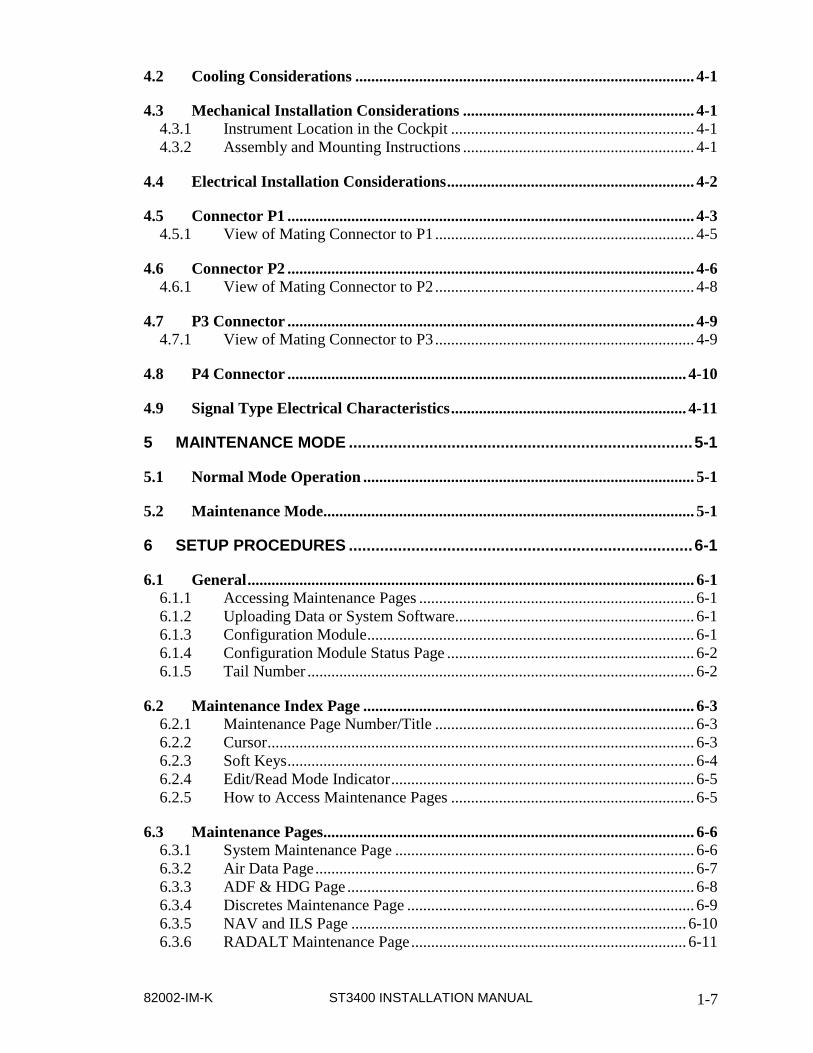
4.2 Cooling Considerations ..................................................................................... 4-1
4.3 Mechanical Installation Considerations .......................................................... 4-1 4.3.1 Instrument Location in the Cockpit ............................................................. 4-1 4.3.2 Assembly and Mounting Instructions .......................................................... 4-1
4.4 Electrical Installation Considerations .............................................................. 4-2
4.5 Connector P1 ...................................................................................................... 4-3 4.5.1 View of Mating Connector to P1 ................................................................. 4-5
4.6 Connector P2 ...................................................................................................... 4-6 4.6.1 View of Mating Connector to P2 ................................................................. 4-8
4.7 P3 Connector ...................................................................................................... 4-9 4.7.1 View of Mating Connector to P3 ................................................................. 4-9
4.8 P4 Connector .................................................................................................... 4-10
4.9 Signal Type Electrical Characteristics ........................................................... 4-11
5 MAINTENANCE MODE ............................................................................. 5-1
5.1 Normal Mode Operation ................................................................................... 5-1
5.2 Maintenance Mode............................................................................................. 5-1
6 SETUP PROCEDURES ............................................................................. 6-1
6.1 General ................................................................................................................ 6-1 6.1.1 Accessing Maintenance Pages ..................................................................... 6-1 6.1.2 Uploading Data or System Software............................................................ 6-1 6.1.3 Configuration Module .................................................................................. 6-1 6.1.4 Configuration Module Status Page .............................................................. 6-2 6.1.5 Tail Number ................................................................................................. 6-2
6.2 Maintenance Index Page ................................................................................... 6-3 6.2.1 Maintenance Page Number/Title ................................................................. 6-3 6.2.2 Cursor ........................................................................................................... 6-3 6.2.3 Soft Keys ...................................................................................................... 6-4 6.2.4 Edit/Read Mode Indicator ............................................................................ 6-5 6.2.5 How to Access Maintenance Pages ............................................................. 6-5
6.3 Maintenance Pages............................................................................................. 6-6 6.3.1 System Maintenance Page ........................................................................... 6-6 6.3.2 Air Data Page ............................................................................................... 6-7 6.3.3 ADF & HDG Page ....................................................................................... 6-8 6.3.4 Discretes Maintenance Page ........................................................................ 6-9 6.3.5 NAV and ILS Page .................................................................................... 6-10 6.3.6 RADALT Maintenance Page ..................................................................... 6-11
ST3400 INSTALLATION MANUAL 82002-IM-K 1-8
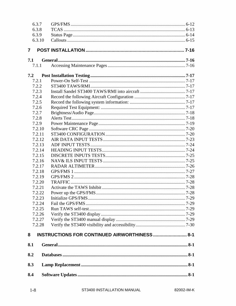
6.3.7 GPS/FMS ................................................................................................... 6-12 6.3.8 TCAS ......................................................................................................... 6-13 6.3.9 Status Page ................................................................................................. 6-14 6.3.10 Callouts ...................................................................................................... 6-15
7 POST INSTALLATION ............................................................................ 7-16
7.1 General .............................................................................................................. 7-16 7.1.1 Accessing Maintenance Pages ................................................................... 7-16
7.2 Post Installation Testing .................................................................................. 7-17 7.2.1 Power-On Self-Test ................................................................................... 7-17 7.2.2 ST3400 TAWS/RMI .................................................................................. 7-17 7.2.3 Install Sandel ST3400 TAWS/RMI into aircraft ....................................... 7-17 7.2.4 Record the following Aircraft Configuration ............................................ 7-17 7.2.5 Record the following system information: ................................................ 7-17 7.2.6 Required Test Equipment: ......................................................................... 7-17 7.2.7 Brightness/Audio Page............................................................................... 7-18 7.2.8 Alerts Test .................................................................................................. 7-18 7.2.9 Power Maintenance Page ........................................................................... 7-19 7.2.10 Software CRC Page ................................................................................... 7-20 7.2.11 ST3400 CONFIGURATION ..................................................................... 7-20 7.2.12 AIR DATA INPUT TESTS ....................................................................... 7-23 7.2.13 ADF INPUT TESTS .................................................................................. 7-24 7.2.14 HEADING INPUT TESTS ........................................................................ 7-24 7.2.15 DISCRETE INPUTS TESTS ..................................................................... 7-25 7.2.16 NAV& ILS INPUT TESTS ....................................................................... 7-25 7.2.17 RADAR ALTIMETER .............................................................................. 7-26 7.2.18 GPS/FMS 1 ................................................................................................ 7-27 7.2.19 GPS/FMS 2 ................................................................................................ 7-28 7.2.20 TRAFFIC ................................................................................................... 7-28 7.2.21 Activate the TAWS Inhibit ........................................................................ 7-28 7.2.22 Power up the GPS/FMS ............................................................................. 7-28 7.2.23 Initialize GPS/FMS .................................................................................... 7-29 7.2.24 Fail the GPS/FMS ...................................................................................... 7-29 7.2.25 Run TAWS self-test ................................................................................... 7-29 7.2.26 Verify the ST3400 display ......................................................................... 7-29 7.2.27 Verify the ST3400 manual display ............................................................ 7-29 7.2.28 Verify the ST3400 visibility and accessibility ........................................... 7-30
8 INSTRUCTIONS FOR CONTINUED AIRWORTHINESS .......................... 8-1
8.1 General ................................................................................................................ 8-1
8.2 Databases ............................................................................................................ 8-1
8.3 Lamp Replacement ............................................................................................ 8-1
8.4 Software Updates ............................................................................................... 8-1

82002-IM-K ST3400 INSTALLATION MANUAL 1-9
9 INSTALLATION DRAWINGS .................................................................... 9-1
10 APPENDIX A: EQUIPMENT AND INTERFACES .................................. 10-1
10.1 GPS/FMS .......................................................................................................... 10-1 10.1.1 ARINC 429 LABELS for GPS/FMS ......................................................... 10-2
10.2 RADAR ALTIMETER .................................................................................... 10-2 10.2.1 ARINC 429 LABELS for Radar Altimeter ............................................... 10-3
10.3 HEADING ........................................................................................................ 10-3 10.3.1 ARINC 429 LABELS for Heading ............................................................ 10-3
10.4 ADF ................................................................................................................... 10-3 10.4.1 ARINC 429 LABELS for ADF ................................................................. 10-3
10.5 NAV ................................................................................................................... 10-3 10.5.1 ARINC 429 LABELS for NAV ................................................................. 10-3
10.6 AIRDATA ......................................................................................................... 10-4 10.6.1 ARINC 429 LABELS for Airdata ............................................................. 10-4
10.7 TRAFFIC .......................................................................................................... 10-4
11 APPENDIX B: ENVIRONMENTAL QUALIFICATION FORM ................. 11-1
12 APPENDIX C: STC ................................................................................. 12-1
12.1 STC Permission ................................................................................................ 12-1
12.2 STC: Cessna 421C Series ............................................................................... 12-2
12.3 STC: King Air C90, 200, 300 and B300 Series ............................................. 12-3

ST3400 INSTALLATION MANUAL 82002-IM-K 1-10
1 GENERAL INFORMATION
1.1 Introduction The information contained within this Installation Manual describes the features, functions, technical characteristics, components, approval procedures, installation considerations, setup procedures, checkout procedures and instructions for continued airworthiness for the Sandel Avionics ST3400 TAWS/RMI.
Sandel Avionics ST3400 TAWS/RMI may be covered by one or more U.S. and foreign patents and pending patent applications, including U.S. Patent Nos. 6,507,288, 6,489,916, and 6,259,378.
1.1.1 MOD-A Status
Certain enhancements exist on units marked as “MOD-A” on the dataplate. These enhancements cannot be retrofitted to to non MOD-A units.
1. The display has higher resolution 2. 2nd audio output available which can drive 8 ohm speaker directly 3. Availability of auto dimming of the display from the Pilot’s Menu. 4. Cooling Fan will cycle off below approximately 0° C 5. Self-test will operate all annunciator outputs. 6. Capability of interfacing to CIC brand analog airdata Computers
Mod-A status can be determined from the data plate, or from the Pilot’s Menu where the Mod-A status is shown in the upper right of the screen.
NOTE: See section on software loading for other information about MOD-A.
1.1.2 MOD-B Status
MOD-B units contain the same enhancements as MOD-A units and have even higher display resolution.
Mod-B status can be determined from the TSO label, or from the Pilot’s Menu where the Mod-B status is shown in the upper right of the screen.
NOTE: See section on software loading for other information about MOD-B.
1.2 Descriptions
1.2.1 ST3400 TAWS/RMI Description
The Sandel ST3400 is a self-contained TAWS (Terrain Awareness Warning System) solution that includes a TAWS computer and an integrated full-color screen, built within a standard 3-inch instrument chassis.
It can be used as a direct replacement for a currently installed RMI (Radio Magnetic Indicator).

82002-IM-K ST3400 INSTALLATION MANUAL 1-11
The ST3400 uses Sandel’s patented rear-projection display technology. The projector uses a miniature active-matrix LCD display that produces a high-resolution image that is rear-projected directly to the face of the instrument. This technology allows the displayed image to extend to the edges of the instrument’s bezel. The advantage of this edge-to-edge technology is that it eliminates the unusable area surrounding conventional LCD and CRT displays. Even though the Sandel display is in a 3-inch form factor, its image is near the size of a 4” primary display, and it remains directly in the pilot’s field-of-view.
The ST3400 includes built-in warning and caution annunciation. The unit also supports optional external warning or caution annunciation.
The ST3400 may be installed in a pilot-only or dual pilot/copilot configuration.
The ST3400 has an internal recorder that automatically records ten hours of flight data. This data can be reviewed for content in the event of a system malfunction.
1.2.2 TAWS Description
TAWS is the enhanced terrain warning technology that replaces the older GPWS (Ground Proximity Warning System) technology. It is also known as EGPWS (Enhanced GPWS).
TAWS adds two new and critical capabilities, FLTA (Forward Looking Terrain Avoidance) and PDA (Premature Decent Alert) to the standard GPWS functions.
The six standard GPWS functional modes are: • ERD (excessive rate of descent) • ECRT (excessive closure rate to terrain) • ALAT (altitude loss after takeoff) • FITNL (flight into terrain when not in landing configuration) • EDGSD (excessive downward glide slope deviation). • 500’ Voice Callout
The ST3400 can be configured either as a Class A TAWS compliant system or as a Class B TAWS compliant system depending on the availability of radar altimeter and airdata.
When configured as a Class B TAWS system, the ST3400 exceeds Class B TAWS requirements. Even in Class B mode without radar altimeter, the ST3400 has additional Class A features such as a display and an excessive glide slope deviation alert. See the POH for additional information
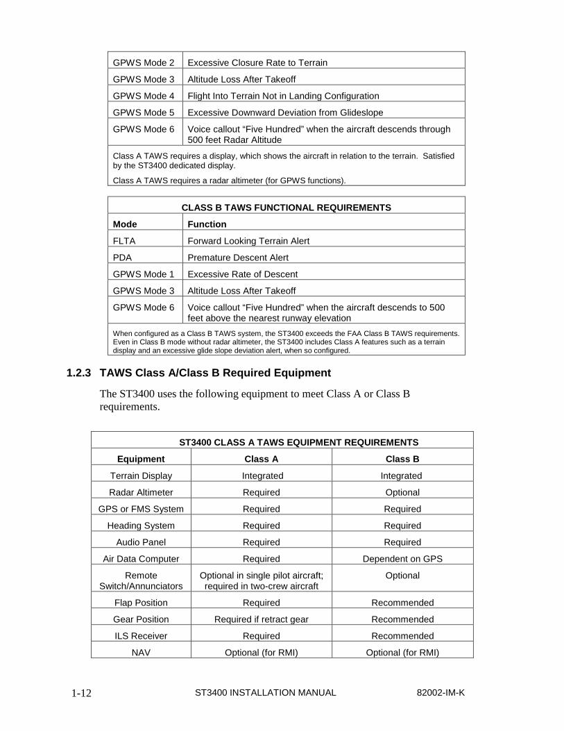
CLASS A TAWS FUNCTIONAL REQUIREMENTS
Mode Function
FLTA Forward Looking Terrain Alert
PDA Premature Descent Alert
GPWS Mode 1 Excessive Rate of Descent
ST3400 INSTALLATION MANUAL 82002-IM-K 1-12
GPWS Mode 2 Excessive Closure Rate to Terrain
GPWS Mode 3 Altitude Loss After Takeoff
GPWS Mode 4 Flight Into Terrain Not in Landing Configuration
GPWS Mode 5 Excessive Downward Deviation from Glideslope
GPWS Mode 6 Voice callout “Five Hundred” when the aircraft descends through 500 feet Radar Altitude
Class A TAWS requires a display, which shows the aircraft in relation to the terrain. Satisfied by the ST3400 dedicated display.
Class A TAWS requires a radar altimeter (for GPWS functions).
CLASS B TAWS FUNCTIONAL REQUIREMENTS
Mode Function
FLTA Forward Looking Terrain Alert
PDA Premature Descent Alert
GPWS Mode 1 Excessive Rate of Descent
GPWS Mode 3 Altitude Loss After Takeoff
GPWS Mode 6 Voice callout “Five Hundred” when the aircraft descends to 500 feet above the nearest runway elevation
When configured as a Class B TAWS system, the ST3400 exceeds the FAA Class B TAWS requirements. Even in Class B mode without radar altimeter, the ST3400 includes Class A features such as a terrain display and an excessive glide slope deviation alert, when so configured.
1.2.3 TAWS Class A/Class B Required Equipment
The ST3400 uses the following equipment to meet Class A or Class B requirements.
ST3400 CLASS A TAWS EQUIPMENT REQUIREMENTS
Equipment Class A Class B
Terrain Display Integrated Integrated
Radar Altimeter Required Optional
GPS or FMS System Required Required
Heading System Required Required
Audio Panel Required Required
Air Data Computer Required Dependent on GPS
Remote Switch/Annunciators
Optional in single pilot aircraft; required in two-crew aircraft
Optional
Flap Position Required Recommended
Gear Position Required if retract gear Recommended
ILS Receiver Required Recommended
NAV Optional (for RMI) Optional (for RMI)

82002-IM-K ST3400 INSTALLATION MANUAL 1-13
ADF Optional (for RMI) Optional (for RMI)
OAT Probe Required for Corrected Baro Alt Required for Corrected Baro Alt
1.2.4 FAA TAWS Requirement by Type of Operation
The FAA has mandated that all U.S.-registered turbine powered aircraft that have six or more passenger seats be equipped with a TAWS no later than March 5, 2005.
Depending on the number of seats and the type of operation, the TAWS requirement will be for a Class A system or a Class B system.
FAA TAWS REQUIREMENT BY TYPE OF OPERATION
Class Type of Operation Number of Passenger Seats
Class A FAR Part-121 ALL
Class A FAR Part-135 10 or more
Class B FAR Part-135 6-9
Class B FAR Part-91 6 or more
1.2.5 RMI Description
The ST3400 RMI function is provided to allow the ST3400 to replace an existing installed electromechanical RMI. The Sandel RMI displays aircraft heading information on a calibrated compass card read against a fixed lubber line.
Bearing is provided to both a primary pointer and a secondary pointer, each of which is read against the compass card.
Each pointer may be switched independently to any installed navigation source, which may be a VOR, ADF, or the GPS/FMS waypoint. The ability to assign the GPS/FMS to a bearing pointer is unique to the ST3400 RMI.
If the navigation source has an invalid state available, the associated bearing pointer will be removed completely from the display instead of being parked at 90° as is common in mechanical RMI’s. Each pointer may be independently turned on or off and independently selected to the aircraft navigation sources.
1.2.6 Terrain Database
The ST3400 provides predictive “look ahead” warnings by comparing it’s internal terrain database to positioning information provided by the GPS, INS, or FMS system. The terrain database includes obstacles. For a Class A installation, additional information is received from a radar altimeter. Altitude information is received from GPS or airdata computer.

ST3400 INSTALLATION MANUAL 82002-IM-K 1-14
1.2.7 Coverage area of the databases
The internal databases of the ST3400 contain terrain including charted man-made obstacles, and airports with runways greater than 2500 feet in length or as indicated in the airport database notes. Obstacles are not shown discretely, but are included in the terrain cells. This means, for instance, that flat terrain with a charted broadcast antenna may show the terrain cell containing the antenna as Yellow when all the surrounding terrain shows as Green.
The Terrain and Airport databases are provided by geographical area. The coverage area of the database installed in the ST3400 is shown as part of the sign-on screen after a power cycle.
Obstacle data from North America and Europe is currently incorporated in the respective terrain databases. Additional obstacle data will be included as more obstacles become charted and information becomes available.
Remember, there is no guarantee that every obstacle is charted or that every charted obstacle is in the terrain data.
1.2.8 Keeping the databases current
Updates to the coverage area databases can be obtained on CD ROM from Sandel or downloaded from the Sandel web site into a Windows loader program on a laptop computer. The terrain data and/or airport data is then downloaded from the PC into the ST3400 through a high-speed USB port located on the front right corner. Loading instructions are supplied along with the applicable database.
The databases can be updated during normal maintenance to the aircraft.
Note: since USB is not supported in Windows-95, only Windows-98 (and later) Microsoft operating systems are supported.
1.3 Technical Specifications The following section describes the technical characteristics, which include the appliance approval basis, physical and electrical properties, electrical connector pin allocation which details function and gradient or equipment protocol, and ARINC label support. Also included is the description of the ST3400 installation components, other equipment and installation requirements. A review of the installation approval procedures is provided for filing with authorities.
1.3.1 Approval Data
Technical Standard Order: TSO-151b (Class A/Class B) *
TSO-C113
Software Certification: DO-178B
Environmental: DO-160D
Databases: DO-200A
82002-IM-K ST3400 INSTALLATION MANUAL 1-15
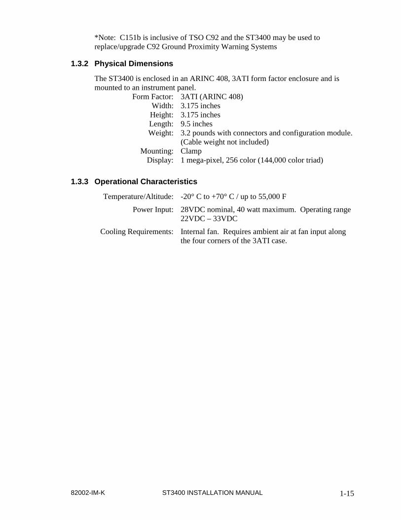
*Note: C151b is inclusive of TSO C92 and the ST3400 may be used to replace/upgrade C92 Ground Proximity Warning Systems
1.3.2 Physical Dimensions
The ST3400 is enclosed in an ARINC 408, 3ATI form factor enclosure and is mounted to an instrument panel.
Form Factor: 3ATI (ARINC 408) Width: 3.175 inches Height: 3.175 inches Length: 9.5 inches Weight: 3.2 pounds with connectors and configuration module.
(Cable weight not included) Mounting: Clamp
Display: 1 mega-pixel, 256 color (144,000 color triad)
1.3.3 Operational Characteristics
Temperature/Altitude: -20° C to +70° C / up to 55,000 F
Power Input: 28VDC nominal, 40 watt maximum. Operating range 22VDC – 33VDC
Cooling Requirements: Internal fan. Requires ambient air at fan input along the four corners of the 3ATI case.
ST3400 INSTALLATION MANUAL 82002-IM-K 1-16
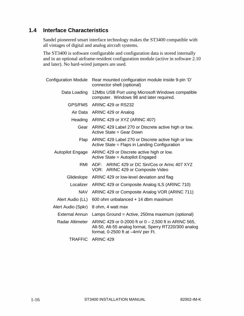
1.4 Interface Characteristics Sandel pioneered smart interface technology makes the ST3400 compatible with all vintages of digital and analog aircraft systems.
The ST3400 is software configurable and configuration data is stored internally and in an optional airframe-resident configuration module (active in software 2.10 and later). No hard-wired jumpers are used.
Configuration Module Rear mounted configuration module inside 9-pin ‘D’
connector shell (optional)
Data Loading 12Mbs USB Port using Microsoft Windows compatible computer. Windows 98 and later required.
GPS/FMS ARINC 429 or RS232
Air Data ARINC 429 or Analog
Heading ARINC 429 or XYZ (ARINC 407)
Gear ARINC 429 Label 270 or Discrete active high or low. Active State = Gear Down
Flap ARINC 429 Label 270 or Discrete active high or low. Active State = Flaps in Landing Configuration
Autopilot Engage ARINC 429 or Discrete active high or low. Active State = Autopilot Engaged
RMI ADF: ARINC 429 or DC Sin/Cos or Arinc 407 XYZ VOR: ARINC 429 or Composite Video
Glideslope ARINC 429 or low-level deviation and flag
Localizer ARINC 429 or Composite Analog ILS (ARINC 710)
NAV ARINC 429 or Composite Analog VOR (ARINC 711)
Alert Audio (LL) 600 ohm unbalanced + 14 dbm maximum
Alert Audio (Spkr) 8 ohm, 4 watt max
External Annun Lamps Ground = Active, 250ma maximum (optional)
Radar Altimeter ARINC 429 or 0-2000 ft or 0 – 2,500 ft in ARINC 565, Alt-50, Alt-55 analog format, Sperry RT220/300 analog format, 0-2500 ft at –4mV per Ft.
TRAFFIC ARINC 429
82002-IM-K ST3400 INSTALLATION MANUAL 1-17
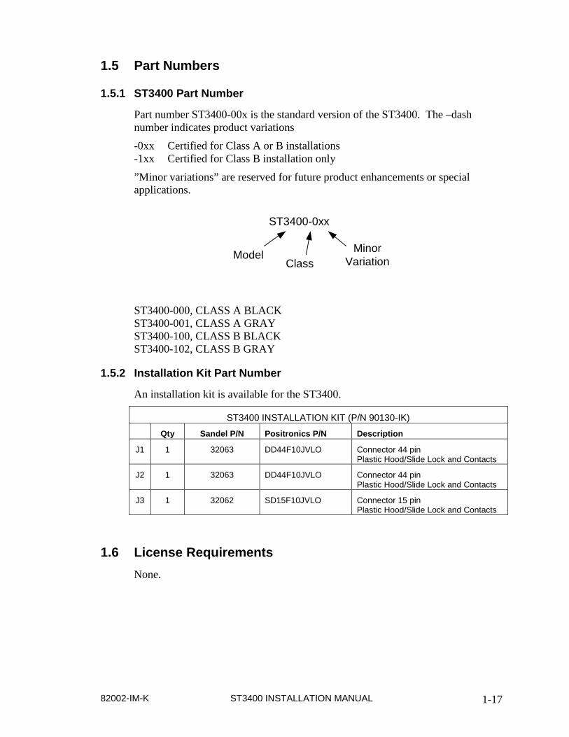
1.5 Part Numbers
1.5.1 ST3400 Part Number
Part number ST3400-00x is the standard version of the ST3400. The –dash number indicates product variations
-0xx Certified for Class A or B installations -1xx Certified for Class B installation only
”Minor variations” are reserved for future product enhancements or special applications.
Model MinorVariation
ST3400-0xx
Class
ST3400-000, CLASS A BLACK ST3400-001, CLASS A GRAY ST3400-100, CLASS B BLACK ST3400-102, CLASS B GRAY
1.5.2 Installation Kit Part Number
An installation kit is available for the ST3400.
ST3400 INSTALLATION KIT (P/N 90130-IK)
Qty Sandel P/N Positronics P/N Description
J1 1 32063 DD44F10JVLO Connector 44 pin Plastic Hood/Slide Lock and Contacts
J2 1 32063 DD44F10JVLO Connector 44 pin Plastic Hood/Slide Lock and Contacts
J3 1 32062 SD15F10JVLO Connector 15 pin Plastic Hood/Slide Lock and Contacts
1.6 License Requirements None.

ST3400 INSTALLATION MANUAL 82002-IM-K 1-18
1.7 Technical Standard Order Stipulation The following stipulation as presented is required by the federal Aviation Administration for articles approved under Technical Standard Order. This statement does not preclude multiple installation and operational approvals in regard to specific aircraft make, model, or type:
The conditions and tests required for TSO approval of this article are minimum performance standards. It is the responsibility of those installing this article either on or within a specific type or class of aircraft to determine that the aircraft installation conditions are within the TSO standards. TSO articles must have separate approval for installation in an aircraft. The article may be installed only in compliance with 14 CFR Part 43 or the applicable airworthiness requirements.
1.8 Installation and Operational Approval Procedures The Environmental Qualification Form for the ST3400 is included as an Appendix within this Installation Manual. It should be referenced to the categories appropriate to the aircraft type and environment into which the ST3400 is to be installed. The environmental category for the ST3400 should be stipulated on the STC form.
A “Functional Ground Test Procedures/Report” and an “Operational Flight Check Procedures Report” are included in an Appendix to this manual. They should be used as a basis for validating the ST3400 equipment configuration and to verify proper installation and functional performance. A permanent copy of the STC form must be filed and maintained by the installing agency. Another copy must be presented to the aircraft owner for entry into the aircraft maintenance records, as well as a copy forwarded to Sandel Avionics along with the Warranty Registration Form, to be filed after completion and installation acceptance.
If any difficulty is experienced with the functionality or operational performance of the ST3400, contact Sandel for assistance.

82002-IM-K ST3400 INSTALLATION MANUAL 2-1
2 INSTALLATION PLANNING The ST3400 has been designed to ensure maximum interoperability with all types avionics. Contact Sandel with any questions about interfacing to specific avionics equipment not covered in the installation drawings in this manual.
2.1 General Information To simplify installation, after signals are wired to the ST3400 pins, on-screen setups are used in a post-installation procedure. Maintenance menu pages provide a function selection capability. For most FMS systems, selections are made by equipment make and model.
Refer to the installation schematics in an Appendix of this manual for details on connecting required components.
2.2 Allowed Sensor Configuration Matrix – Class A
2.2.1 Required Sensors (Class-A) 1. Heading 2. GPS position 3. Localizer and Glideslope 4. Radar Altitude 5. Baro Rate (Vertical Speed) 6. Flaps 7. Gear (only if the aircraft has retractable gear).
2.2.2 Additional Required Sensors, allowed configurations (Class-A)
Config GPS Alt Corr. Baro Alt Press. Alt OAT 1 x x x 2 x x 3 x x
(Item shown blank not required)
Contact factory for configurations other than those listed.
2.3 Allowed Sensor Configuration Matrix – Class B
2.3.1 Required Sensors (Class-B) 1. Heading 2. GPS position

ST3400 INSTALLATION MANUAL 82002-IM-K 2-2
2.3.2 Additional Required Sensors, allowed configurations (Class-B)
Config GPS Alt Corr. Baro Alt Baro Rate (VS) OAT
1 x 2 x x x
(item shown blank not required) Contact factory for configurations other than those listed.
2.3.3 Optional Capabilities for Class-B, needed Sensors
The following chart will assist in installation planning to add capabilities in exceedence of Class-B requirements. Without these capabilities GPWS modes 2, 4 and 5 are inoperative. With all the capabilities enabled full Class-A performance is provided, which provides autonomous GPWS protection if the GPS/FMS should fail.
Capability Desired Sensors Needed GPWS Mode-2 ECRT Radar Altitude; Baro Rate (VS); Flaps; Gear2 Optional GPWS Mode-4 FITNL Radar Altitude, Baro Rate (VS); Flaps; Gear2 GPWS Mode-5 Glideslope1 Localizer; Glideslope; Gear2 and/or Flaps 1 Sandel recommended. 2 Req’d only on retractable-gear aircraft
2.4 Altitude Sources and Airdata Airdata hookup is one of the more complex installation planning issues since there are many variations in types of airdata systems. This is particularly true of aircraft upgraded for RVSM, where the altitude source may be a new digital altimeter but the VS source may be the original airdata computer, which has been left in the aircraft to interface with other existing systems. In order to make a flexible system that requires as little additional equipment as possible, the ST3400 supports separate selection of sources for Altitude, Vertical Speed, and OAT. Please pay careful attention this fact when planning installation. See section 2.4.1 Airdata System Block Diagram.
ST3400 software 1.05 and earlier requires Corrected Barometric Altitude for either Class-A or Class-B installations. ST3400 software 2.00 and later supports GPS altitude or Corrected Barometric Altitude, or both. If both are supplied CBA is used as a backup to GPS altitude if available. See the installation diagrams for a list of approved receivers which can supply GPS altitude to the ST3400
For Class-A, at a minimum Barometric Vertical Speed and Barometric Altitude (either corrected or uncorrected) is required. This is used for the classic GPWS portion of the alerting system, such as mode-1 “Excessive Descent Rate” etc.
For Class-B, if GPS altitude is used, no other source of altitude is required; i.e. airdata is not required.

82002-IM-K ST3400 INSTALLATION MANUAL 2-3
2.4.1 Airdata System Block Diagram
Vert Spd Baro Alt OAT
Analog Alt
Coarse/Fine
Analog Vert Spd
Analog TAS
Analog OAT
429 Data
419 Data
Ternary Data
“Ana
log”
“D
igita
l”
Inpu
ts
TAS
Outputs to System
Maintenance Page Selects
ST3400 INSTALLATION MANUAL 82002-IM-K 2-4
2.4.2 OAT Requirements
If Corrected Barometric Altitude is used as an input to the system (see above), a source of OAT is required. This is used to compensate for cold weather errors in the altitude readings. At extremely cold temperature these errors can be in excess of a thousand feet.
The source of OAT can be internal (a probe connected to the ST3400) or from the airdata system. Most digital airdata systems provide, and the ST3400 can accept digital OAT. If this data is not supplied or an analog airdata system is used, an OAT probe is connected directly to the ST3400 to provide OAT.
NOTE: The internal OAT probe is only supported in ST3400 software version 2.00 or later.
2.5 Pre-installation Planning The installation planning cycle is summarized as follows:
1. Determine the desired functional characteristics for the installation.
2. Compile an equipment list for the aircraft. - For Class-A installations ensure the radar altimeter model provides an acceptable 2000’ or 2500’ maximum altitude. - GPS altitude data from approved receivers may be used to supply altitude. See above discussion of “altitude sources” - Airdata may be required. See above discussion of “altitude sources” - See above discussion of “OAT” above to determine the requirement for OAT probe. - If the desired equipment is not listed in the installation manual diagrams, contact Sandel for interoperability
3. Review the installation considerations given in the Installation Considerations section of this manual.
4. Study the installation drawings to determine a basic interconnect scheme and check for conflicts.
5. Develop the specific wiring diagrams unique to the aircraft.
6. Assemble required tools. Recommended crimp tools are given in the following table.

82002-IM-K ST3400 INSTALLATION MANUAL 2-5
Recommended Crimp Tools High Density
22-28 AWG Standard Density
20-24 AWG
Hand Crimping Tool
Positioner
Insertion/ Extraction Tool
Positioner
Insertion/ Extraction Tool
Military P/N M22520/2-01 M22520/2-09 M81969/1-04 M22520/2-08 M81969/1-02
Positronic 9507 9502-3 M81969/1-04 9502-5 M81969/1-02
ITT Cannon 995-0001-584 995-0001-739 N/A 995-0001-604 980-2000-426
AMP 601966-1 601966-6 91067-1 601966-5 91067-2
Daniels AFM8 K42 M24308/18-1 K13-1 M24308/1-02
Astro 615717 615725 M81969/1-02 615724 M81969/1-02
2.6 Post Installation Procedures Post installation procedures are summarized as follows:
1. Prior to power-up, review correct wiring by using industry accepted ohmmeter and voltage checks. Pay particular attention to presence of +28V on only the correct pins; 0 ohm resistance check on ground pins to airframe ground; and presence of inverter 400Hz (if used) only on the appropriate pins.
2. Review any special items particular to the subject aircraft installation.
3. Power up the ST3400 in maintenance mode and sequentially access each maintenance page to select the installed equipment.
4. Check proper cooling airflow:
A. Allow the unit to operate for 30 minutes.
B. Check the internal temperature readout on the appropriate maintenance page for an approximate temperature rise (approximately 10°C or 18°F over ambient).
5. Perform Ground Test procedures.
6. Perform Flight Test procedures if required.

ST3400 INSTALLATION MANUAL 82002-IM-K 2-6
THIS PAGE INTENTIONALLY LEFT BLANK

82002-IM-K ST3400 INSTALLATION MANUAL 3-1
3 INTERFACE FUNCTIONS
3.1 Dual Inputs The ST3400 contains two sets of inputs for each equipment type; for instance, there are two sets of heading inputs. In general (with some exceptions) the “primary” inputs are on P1 and the “secondary” inputs are on P2. Secondary inputs are always optional.
The ST3400 does not contain any internal comparator functions to compare the two sets of inputs. However, it will revert to the secondary input if the primary input flags or fails. This feature may be helpful to improve the system reliability of an aircraft installation. If the #1 inputs fails (such as FMS1 failure) the #2 input will become operational within 5 seconds of the failure; typically within 2 seconds.
3.2 Power The primary two-wire power is 28 volt dc on J-3 and is supplied from the aircraft avionics buss through a circuit breaker. Ground is provided on J-3 and should be attached to an approved airframe ground.
Two 26 volt 400hz excitation inputs are available, if required. One is located on J-1 and the other on J-2. They are labeled as inverter-1 and inverter-2. All signals on J-1 that require excitation must use the same excitation as the inverter-1 input. All signals on J-2 (if used) that require excitation must use the same excitation as the inverter-2 input. If the installation of the ST3400 does not use any XYZ (ARINC407) signal sources, the inverter inputs are not required and should be grounded.
3.3 External Annunciators Optional external annunciator lamp discrete outputs are available to drive TAWS INH, FLAP OVRD, G/S OVRD, CAUT, WARN, annunciators on J-3. A 6th annunciator output can be selected to be either TCAS INH (activates on either Caution or Warning), GPWS FAIL which duplicates the on-screen GPWS FAIL annunciation, TCAS IND which is discrete feedback to TCAS processors when the ST3400 is used as the primary TCAS indicator, or AUDIO ENA which may be used to activate a relay whenever ST3400 audio is present, including maintenance test audio.
TAWS INH is a switch /annunciator and performs the same function as the on-screen TAWS INHIBIT function. FLAP OVRD is a switch /annunciator and performs the same function as the on-screen FLAP OVRD function. G/S OVRD is a switch /annunciator and performs the same function as the on-screen G/S OVRD function.
These circuits are capable of sinking a maximum of 250 milliamps to ground and can drive incandescent lamps. Dimming of the external annunciators is accomplished by sourcing the annunciators from the aircraft day/night bus.

3-2 ST3400 INSTALLATION MANUAL 82002-IM-K
Proper labeling and color must be followed if the external lamp option is used. EXTERNAL ANNUNCIATORS
Annunciator Color Lamp Description
WARN RED Same as on-screen Red Warning
CAUT AMBER Same as on-screen Amber Caution
TAWS INH AMBER Same function as on-screen TAWS INH annunciation
FLAP OVRD AMBER Same function as on-screen FLAP OVRD annunciation .
G/S OVRD AMBER Same function as on-screen G/S OVRD annunciation.
GPWS FAIL AMBER Same function as on-screen GPWS FAIL annunciation
3.4 Flaps The ST3400 has provisions on J-2 for Flaps In Landing Configuration input. This is obtained from either a discrete input (Flaps Down) Arinc 429 label 270 source, or XYZ. This input is required for Class A and recommended for Class B.
Flaps input is required for Class A compliance and is recommended for Class B. Note that for Class-A if flaps are misconfigured to ‘NONE’ a GPWS FAIL indication will appear on the display.
Configuration is performed in the Maintenance Menu pages given in the Setup Procedures section of this manual. If the installation aircraft uses flaps for normal takeoff, ensure that this input triggers in landing configuration not in takeoff configuration
3.5 Landing Gear Landing Gear Position input is required for Class A compliance and is recommended for Class B (if aircraft is retractable gear).
The ST3400 has provisions on J-2 for Gear Down input discrete to indicate that the gear is in the “DOWN” position.
The configuration is performed in the Maintenance Menu pages given in the Setup Procedures section of this manual. If the system is installed in an aircraft without a retractable landing gear, select “NONE” on maintenance page configuration item.
3.6 Autopilot The ST3400 has provisions on J-2 for discrete input signals to obtain an indication of Autopilot Engage. The input signals are used to modify alerting characteristics.
The Autopilot Engaged discrete is configurable for either valid High (<14vdc off, >14vdc on) or valid Low (<3.5vdc on, >3.5vdc off).

82002-IM-K ST3400 INSTALLATION MANUAL 3-3
The configuration is performed in the Maintenance Menu pages given in the Setup Procedures section of this manual.
3.7 Audio Panel The Audio output is required for Class A and Class B compliance. The ST3400 has provisions for low level audio output located on J1-30 and simultaneous direct speaker audio on J1-15 for units with mod-A. The LL audio output must interface to the un-switched audio input of the aircraft audio system.
The audio output produces the GPWS “whoop-whoop” as well as human voice callouts. The LL audio output is the ‘master level’ and the ‘speaker audio’ has a separate adjustment on the installation maintenance page to trim the speaker level relative to the headphone level. If after adjustment the available speaker audio level is insufficient, turn up the master audio level at the ST3400 and make a corresponding reduction in the LL audio level at the headphone amplifier.
The overall level is based on the nominal and maximum audio level configuration. The maximum audio level is a maximum of four (4) times the nominal audio level. The audio level automatically ranges from the Nominal Audio Level to the Maximum Audio Level as the aircraft airspeed increases.
3.8 GPS/FMS A Global Positioning System (GPS) or Flight Management System (FMS) input is required for both Class A and Class B compliance.
Note: This system must be GPS-based system and meet TSO-C129a or C-145 requirements. GPS is used for lateral positional and to display flight plan information. In certain installations it may also be used for vertical position.
The ST3400 has provisions for one or two simultaneous GPS ARINC 429 receiver ports. The primary port is located on J-1 and the optional secondary port is located on J-2. The receiver ports are configurable in the Maintenance Menu pages for High or Low speed ARINC. A list of supported Labels is given in an Appendix of this manual.
3.9 Radar Altimeter The Radar Altimeter input is required for Class A compliance and is recommended for Class B.
The ST3400 has provisions for one Radar Altimeter input. The primary input is located on J-1. (With the exception of the RA FAIL input, see below). Radar Altimeter input may be from an ARINC 429 or DC Analog sources. The Radar Altimeter input is used to obtain Height Above Terrain for GPWS alerting. The ST3400 will support 2000 ft Radar Altimeters such as the Collins ALT-50A in either Class A or Class B installations. The radar altimeter may be connected using its analog outputs or through an existing analog-to-429 converter.
The ST3400 will accept analog ALT50/55, ARINC 552, KRA10 and other analog type inputs.

3-4 ST3400 INSTALLATION MANUAL 82002-IM-K
The RA1 FAIL input is located on J2. The input is normally connected to the RA indicator power at either the RA R/T unit or the RA indicator. When < 10VDC this signal will cause the RA input to assume the FAIL state regardless of the state of the signal or Valid input.
The radar altimeter always produces a ‘500’ audio callout during descent to landing. Optionally the installer may select any or all of the following additional audio callouts when the aircraft is in a descent in the landing configuration:
400’, 300’, 200’, 100’, 50’, 40’, 30’, 20’, 10’
An additional discrete input is available for connection to a Decision Height setter. The ST3400 will provide an audio callout “MINIMUMS” when Decision Height input is asserted.
Note: The Radar Altimeter model must be able to provide information to the ST3400 through at least 2000’. Check the Radar Altimeter installation manual
3.10 Heading System Heading input is required. Heading information is used to obtain magnetic direction of the aircraft for use by the RMI. The Heading information may be available from many sources, such as AHRS, INS, and Slaved Compass systems.
The ST3400 has provisions for up to two simultaneous Heading System input ports. The primary input port is located on J-1 and the optional port is located on J-2. Either one may be from an ARINC 429 or XYZ (ARINC 407) source configurable in the Maintenance Menu pages. A list of supported Labels is given in an Appendix of this manual.
The XYZ (ARINC 407) is dependent on availability of 26VAC excitation for proper operation. In addition, an optional Gyro Valid input (DC level sensitive) is provided if available from the gyro either valid High or Low. If no valid is provided by the Gyro then valid NONE is selected.
If after 10 seconds no valid XYZ signal is being received an on-screen error message is generated
3.11 ADF Receiver The input of the ADF information is optional and not required for the Class A or Class B TAWS compliance. It is used in an application where the ST3400 is used to replace an existing RMI and ADF operation is desired or required.
The ST3400 has provisions for up to two simultaneous ADF Receiver ports. The optional primary port is located on J-1 and the optional secondary port is located on J-2. Either one may be from an ARINC 429, DC Sin/Cos, or XYZ (ARINC 407) sources. For analog DC Sin/Cos or XYZ receivers, an optional ADF Valid input is supported if the receiver supplies a compatible signal

82002-IM-K ST3400 INSTALLATION MANUAL 3-5
3.12 NAV Receiver and Glideslope This information is required for Class A compliance and recommended for Class B. The ST3400 has provisions for up to two simultaneous VHF Navigation and Glideslope receiver ports; the primary receiver port on J-1 and the optional secondary receiver port on J-2. Either one may be from an ARINC 429 or Analog sources. The NAV input is used for the VOR bearing pointer. The Localizer and Glideslope inputs are used for GPWS mode-5 alerting.
When an ARINC 429 receiver system is used, the same input will carry either VOR or ILS data depending on the receiver tuning. See the appropriate manufacturers manual to confirm the information from the navigation and Glideslope receivers.
Standard analog inputs for Glideslope deviation, Glideslope flag status, and Composite Nav information are also provided and may be used instead of the ARINC 429. If Composite Nav is used, these inputs are not on the same pins as the Arinc inputs and are both located on P2.
An additional discrete input is available for Back Course from the HSI, which is used to automatically disable Glideslope alerting while on a Back Course.
Note: The composite Nav input also decodes localizer when tuned.
3.13 Air Data Computer See above discussion of “Altitude Sources”. Air Data Computer input is required for Class A installations and Class-B installations without GPS altitude. For Class-B installations with GPS altitude airdata may be used as a backup altitude and VS source and is optional.
For Class-A installations using GPS altitude, the airdata system must at least supply Vertical Speed and barometric altitude, either corrected or uncorrected.
For Class-A installations without GPS altitude, the airdata system must supply Vertical Speed, Corrected Baro Altitude, and OAT. If OAT is not supplied by the airdata system directly, a compatible OAT probe may be wired directly to the ST3400.
The ST3400 has provisions for up to two simultaneous Air Data Computer ports depending on model. The primary receiver port on J-1 and the optional secondary receiver port on J-2. Primary Airdata may be from an ARINC 429, Manchester or ARINC 565 secondary analog output source and Secondary Airdata maybe 429 or Manchester only, no #2 Airdata Analog input available.
3.14 OAT Probe The ST3400 supports a single directly connected OAT probe to accommodate airdata computers which supply Corrected Baro Altitude to the ST3400 but do not supply OAT. See installation diagrams for information about compatible probes. OAT is required only when using Corrected Barometric Altitude. If GPS Altitude is used, no OAT probe is required.

3-6 ST3400 INSTALLATION MANUAL 82002-IM-K
3.15 Traffic The ST3400 supports Traffic input via single ARINC 429 High Speed Input on software version 3.00 and above. Traffic may be overlaid on terrain or displayed on a separate TFC screen without terrain.
Some remote traffic processors may require remote switches, see Traffic interface drawings in this manual for these requirements.
If an existing ST3400 installation is being upgraded to display Traffic, please contact the factory for a software key to enable the traffic display.
3.16 ST3400 Interlink Reserved for Future use. In dual installations it is recommend to connect.
3.17 Uploading Equipment A USB interface is available on the front of the ST3400 to upload system software, terrain data, airport data, and configuration data into memory and to download configuration data from memory.
Data is loaded from a PC or laptop computer with Microsoft Windows 98 (or later) operating system software to the ST3400. Drivers, the loader program, and loading instructions are supplied with the applicable software or data.
3.18 Display Dimming The ST3400 screen dimmer is controlled from the Pilot’s Menu using the “M” button. The display and push-button LED luminance levels are coordinated. Units with Mod-A have selectable auto/manual dimming. Units without Mod-A have manual dimming only.
External annunciator dimming may be accomplished using the existing aircraft day/night buss by connecting the high-side of the annunciator lamps day/night buss.
3.19 Windshield Wipers A discrete input signal is provided to increases the audio level to allow the flight crew to hear the aural alerts during high noise conditions.
The Auto Audio Level Increase discrete may be connected to windshield wiper logic to automatically increase the audio level when using high noise windshield rain removal equipment during heavy rain.
Note: This discrete input is a shared function with RA2 FAIL. If the aircraft installation has dual radar altimeters, please contact Sandel for information to access the windshield wiper function through another pin.

82002-IM-K ST3400 INSTALLATION MANUAL 4-1
4 INSTALLATION The ST3400 should be installed in accordance with standards established by the customer’s installing agency, and existing conditions as to unit location and type of installation.
4.1 Unpacking and Inspecting Equipment Exercise extreme care when unpacking the equipment. Make a visual inspection of the unit for evidence of damage incurred during shipment. If a claim for damage is made, save the shipping container to substantiate the claim. The claim should be promptly filed with the carrier. It would be advisable to retain the container and packaging material after all equipment has been removed in the event that equipment storage or reshipment should become necessary.
4.2 Cooling Considerations The ST3400 contains its own ventilation fan for internal component cooling and does not require a forced air cooling system. However, it is extremely important that the perforated area at the four corners (air intakes) be kept clear of any objects which would restrict the inflow of air at cabin ambient temperature.
Cooling should be verified in the post-installation checkout by monitoring the temperature on the Diagnostics 1 page.
For additional cooling or special requirements, air from an external avionics blower may be directed near the corner air inlets.
In helicopter installations it may be desirable to introduce a small amount of cooled (air conditioner) air into the avionics bay if it is completely sealed. In these installations it is not uncommon for the internal ambient temperature of the avionics bay to exceed the ratings of the equipment if cooling air is not supplied.
4.3 Mechanical Installation Considerations
4.3.1 Instrument Location in the Cockpit
The Sandel ST3400 is a direct replacement for a currently installed RMI. Installation should conform to customer requirements and airworthiness standards affecting the location and type of installation.
4.3.2 Assembly and Mounting Instructions
Refer to the ST3400 Installation Diagrams for specific assembly and mounting instructions and appropriate notes.

4-2 ST3400 INSTALLATION MANUAL 82002-IM-K
4.4 Electrical Installation Considerations The installing agency fabricates and supplies all wiring harnesses. Refer to the ST3400 Interconnect Wiring Diagrams for detailed wiring information and appropriate notes.
Refer to the Functional Pinout Descriptions for explanations of pin functions.
1. The length and routing of wires must be carefully planned before starting the installation.
• Avoid sharp bends in the harness. • Do not locate the harness near aircraft controls. • Observe all recommended wire sizes and types and subscribe
to appropriate FAR Parts 23, 25, 27, and 29, as well as AC 43.13-1(B) and –2(A).
2. MIL-C27500 shielded wire and MIL-W-22759 single conductor wire is recommended. The use of ferrules or grounding blocks for signal ground and digital ground returns is satisfactory, however, each ground return must be electrically separated.
3. In order to ensure optimum performance, the ST3400 and associated wiring must be kept a minimum of three feet from high noise sources and not routed with cables from high power sources.
4. Prior to installation, verify proper wiring by completing a point-to-point continuity check of the wiring harness.
5. Use the Functional Pinout Descriptions to determine installation requirements.
6. Ground Bonding. In order to assure installation characteristics match the DO-160 RF and Lightning test conditions, ensure that two ground wires of at least the recommended size are installed in accordance with the installation drawings and these wires are connected to a bonded aircraft ground.
7. Power Wiring. To assure that the ST3400 will operate properly down to its rated minimum input voltage, ensure that two power wires of at least the recommended size are connected in accordance with the installation drawings.

82002-IM-K ST3400 INSTALLATION MANUAL 4-3
4.5 Connector P1 For electrical characteristics, see the table in section 4.9 by referencing the signal type indicated in italics. Signal types enclosed in parentheses indicate functionality that is reserved.
Pin # Name Signal Type (dependent on maintenance page selection)
16 Inverter Exc. In Note: May be same or different than P2-16 inverter source. Inverter 26Vac Excitation for items on connector P1
1 Shield Gnd
31 FMS1A Primary In A429 A side 429 (RS422) + side 422 (RS232) Ground side
17 FMS1B Primary In A429 B side 429 (RS422) - side 422 (RS232) Rx
2 Radalt1A In A429 A side 429 RadAlt Analog DC+ [ALT 50/55, ARINC 552, RT220/300, RT200]
32 Radalt1B In A429 B side (429) RadAlt Analog DC- [ALT 50/55, ARINC 552, RT220/300, RT200]
18 Radalt1 Valid In Discrete Valid Discrete, Note: Not used when 429 is data source
3 Hdg1A In A429 A side 429 A407 Synchro X [Z grounded]
33 Hdg1B In A429 B side 429 A407 Synchro Y [Z grounded]
19 Hdg1 Valid In Discrete Valid Hdg Analog, Note: Not used when 429 is data source.
4 ADF1A In A429 A side 429 DC Sin DC Sine A407 Synchro X [Z grounded]
34 ADF1B In A429 B side 429 DC Cos DC Cosine A407 Synchro Y [Z grounded]
20 ADF1 DC Ref In ADF Ref ADF DC, Note: Not used when 429 or XYZ is data source.
5 ADF1 Valid In Discrete Valid ADF Discrete, Note: Not used when 429 is data source
35 Nav1A In Note: For composite inputs see P2-42 A429 A side 429 (RS422) + side 422 (RS232) Ground side
21 Nav1B In Note: For composite inputs see P2-42 A429 B side 429 (RS422) - side 422 (RS232) Rx

4-4 ST3400 INSTALLATION MANUAL 82002-IM-K
P1 Connector (continued from previous page) Pin # Name Signal Type (dependent on maintenance page selection)
6 GS1 LL Flag In+ In Differential pair to pin 36 GS Flag Note: For use with external SUPERFLAG see installation
drawing for series resistor required.
36 GS1 LL Flag In- In Differential pair to pin 6. GS Flag
22 GS1 LL Dev In +FLY DOWN
In Differential pair to pin 7. GS Polarity: + indicates above glideslope, fly-down indication.
7 GS1 LL Dev In +FLY UP
In Differential pair to pin 22. GS Polarity: + indicates below glideslope, fly-up indication
37 Airdata1A
In A429/419 A side 429/419 (R422) + side 422 (R232) Ground side A407 AC resolver Fine Sine Altitude Synchro X Fine Altitude Manchester High
23 Airdata1B
In A429/419 B side 429/419 (R422) - side 422 (R232) Rx A407 AC resolver Fine Cosine Altitude Synchro Y Fine Altitude Manchester Low
8 Alt1 / VS1 Gnd
In Note: Differential signals paired with pin 39. A429/419 A side 429/419 (R422) + side 422 (R232) Ground side (A407) Synchro X Alt DC Coarse Ground at source
38 VS1 Signal In VS Sig DC voltage - 5V to + 5V = -10,000 to +10000 FPM
24 VS1 Ref- In VS Ref Note: -12Vdc excitation reference
9 VS1 Ref+ In VS Ref Note: +12Vdc excitation reference
39 Alt1 DC Coarse
In Note: Differential signals paired with pin 8. A429/419 B side 429/419 (R422) - side 422 (R232) Rx (A407) Synchro Y Alt DC Coarse High side
25 TAS1 Sig In TAS Sig
10 TAS1 Ref In TAS Sig
40 Airdata1 Valid In Discrete Valid ADC Analog, Note: Not used when 429 is data source.
26 FMS1 A
Secondary
(In) n/c (A429) A side 429 (R422) + side 422 (R232) Ground side (A407) Synchro X
11 FMS1 B Secondary
(In) n/c (A429) B side 429 (R422) - side 422 (R232) Rx (A407) Synchro Y

82002-IM-K ST3400 INSTALLATION MANUAL 4-5
P1 Connector (continued from previous page) Pin # Name Signal Type (dependent on maintenance page selection)
41 Flaps-X / Spare1A
(In) n/c A429/419 A side 429/419 (R422) + side 422 (R232) Ground side (A407) Synchro X (A568) Data
27 Flaps-Y / Spare1B
(In) n/c A429/419 B side 429/419 (R422) - side 422 (R232) Rx (A407) Synchro Y (A568) Clk
12 N/C In n/c A568 Sync
42 429 Out A Out A429 A Side - Alert output to FDR - High Speed (100Kbps)
28 429 Out B Out A429 B Side - Alert output to FDR - High Speed (100Kbps)
13 RS232TxD (Out (R232)
43 n/c In Factory use only DO NOT CONNECT Discrete
29 OAT Probe In Connect other lead to pin-1 GROUND. A575 Excitation
14 n/c n/c
44 n/c n/c
30 Audio LL Out Out Audio LL Low Level Audio output, requires external amplifier
15 Speaker Audio Out
Out Clone of audio from Audio1 which has the capability of driving 8 ohm speaker directly. Volume separately trimmed with respect to LL audio, which acts as master.
Audio Spkr
4.5.1 View of Mating Connector to P1
15
30
44
14
29
43
13
28
42
12
27
41
11
26
40
10
25
39
9
24
38
8
23
37
7
22
36
1
16
6
21
35
5
20
34
4
19
33
3
18
32
2
17
31
Outside View
(Mating Connector)

4-6 ST3400 INSTALLATION MANUAL 82002-IM-K
4.6 Connector P2 For electrical characteristics, see the table in section 4.9 by referencing the signal type indicated in italics. Signal types enclosed in parentheses indicate functionality that is reserved.
Pin # Name Signal Type (dependent on maintenance page selection)
16 Inverter Exc. In Note: May be same or different than P2-16 inverter source. Inverter 26Vac Excitation for items on connector P1
1 Shield Gnd
31 FMS2A Primary In A429 A side 429 (RS422) + side 422 (RS232) Ground side
17 FMS2B Primary In A429 B side 429 (RS422) - side 422 (RS232) Rx
2 TCAS A In A429 A side 429 (RS232) Ground Side
32 TCAS B In A429 B side 429 (RS232) Rx
18 Decision Height Discrete
In Discrete Valid Discrete Open/Gnd or Open/+28VDC
3 Hdg2A In A429 A side 429 A407 Synchro X [Z grounded]
33 Hdg2B In A429 B side 429 A407 Synchro Y [Z grounded]
19 Hdg2 Valid In Discrete Valid Hdg Analog, Note: Not used when 429 is data source.
4 ADF2A In A429 A side 429 DC Sin DC Sine A407 Synchro X [Z grounded]
34 ADF2B In A429 B side 429 DC Cos DC Cosine A407 Synchro Y [Z grounded]
20 ADF2 DC Ref In ADF Ref ADF DC, Note: Not used when 429 or XYZ is data source.
5 ADF2 Valid In Discrete Valid ADF Discrete, Note: Not used when 429 is data source
35 Nav2A In Note: For composite inputs see P2-42 A429 A side 429 (RS422) + side 422 (RS232) Ground side
21 Nav2B In Note: For composite inputs see P2-42 A429 B side 429 (RS422) - side 422 (RS232) Rx

82002-IM-K ST3400 INSTALLATION MANUAL 4-7
P2 Connector (continued from previous page) Pin # Name Signal Type (dependent on maintenance page selection)
6 GS2 LL Flag In+ In Differential pair to pin 36 GS Flag Note: For use with external SUPERFLAG see installation
drawing for series resistor required.
36 GS2 LL Flag In- In Differential pair to pin 6. GS Flag
22 GS2 LL Dev In +FLY DOWN
In Differential pair to pin 7. GS Polarity: + indicates above glideslope, fly-down indication.
7 GS2 LL Dev In +FLY UP
In Differential pair to pin 22. GS Polarity: + indicates below glideslope, fly-up indication
37 Digital Airdata 2A
In A429 /419 A side 429/419 (R422) + side 422 (R232) Ground side Manchester High
23 Digital Airdata 2B
In A429 /419 B side 429/419 (R422 ) - side 422 (R232) Rx Manchester Low
8 Spare Analog 1 In
38 Spare Analog 2 In
24 Flaps Ovrd In Discrete Open/Gnd
9 GS Ovrd In Discrete Open/Gnd
39 Pressure Altitude 1 Analog
In Pressure Altitude 0.25 VDC/1Kft or 0.3175 VDC/1K ft
25 Spare Analog 3 In
10 VS1 Rate (CIC) In 10 VDC +/-5 VDC, 0.5 VDC/1K ft
40 Backcourse (BC) Discrete
In Discrete Valid Discrete Open/Gnd or Open/+28VDC.
26 FMS2 A Secondary
(In) n/c (A429) A side 429 (R422) + side 422 (R232) Ground side
11 FMS2 B Secondary
(In) n/c (A429) B side 429 (R422) - side 422 (R232) Rx
4-8 ST3400 INSTALLATION MANUAL 82002-IM-K
P2 Connector (continued from previous page) Pin # Name Signal Type (dependent on maintenance page selection)
41 Spare
(In) n/c (A429) A side 429 (R422) + side 422 (R232) Ground side (A407) Synchro X (A568) Data
27 Spare
(In) n/c (A429) B side 429 (R422) - side 422 (R232) Rx (A407) Synchro Y (A568) Clk
12 Spare2C (In) n/c (A568) Sync
42 Nav1 Composite In VOR Bearing and Localizer Deviation input. A710, A711 Used when ARINC 429 data is not used
28 Nav2 Composite In VOR Bearing and Localizer Deviation input. A710, A711 Used when ARINC 429 data is not used
13 RA1 FAIL In Discrete Valid If RA1 configured: <14VDC indicates RA 1 Fail
43 Audio Increase In Discrete Valid Activates audio level increase.
29 AP Engage In Discrete Valid
14 Gear Down In Discrete Valid
44 Flaps Ldg In Discrete Valid Indicate flaps are in landing (not takeoff) configuration
30 429A Interlink Out For dual installations to feed cross-side system A429 A side 429
15 429B Interlink Out For dual installations to feed cross-side system A429 B side 429
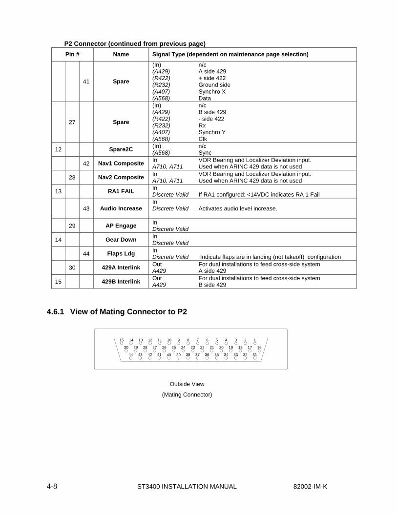
4.6.1 View of Mating Connector to P2
15
30
44
14
29
43
13
28
42
12
27
41
11
26
40
10
25
39
9
24
38
8
23
37
7
22
36
1
16
6
21
35
5
20
34
4
19
33
3
18
32
2
17
31
Outside View
(Mating Connector)

82002-IM-K ST3400 INSTALLATION MANUAL 4-9
4.7 P3 Connector For electrical characteristics, see the table in section 4.9 by referencing the signal type indicated in italics. Signal types enclosed in parentheses indicate functionality that is reserved.
Pin # Name Signal Type (dependent on maintenance page selection)
1 Aircraft Pwr In Power
9 Aircraft Pwr In Power
2 n/c n/c
10 n/c n/c
3 Aircraft Ground In System Ground
11 Aircraft Ground In System Ground
4 GS OVRD Lamp (Out) (Open Drain)
12 FLAPS OVRD Lamp
(Out) (Open Drain)
5 n/c In Factory use only DO NOT CONNECT
13 TAWS INH In Optional external TAWS INH switch Discrete Valid
6 Lamp Test In Optional external enunciator test Discrete Valid
14 Warning Lamp Out Optional Open Drain
7 Caution Lamp Out Optional Open Drain
15 TAWS INH Lamp Out Optional Open Drain
8* Selectable Discrete*
(Out) TCAS INH (TAWS Warn or Caution); -or- GPWS FAIL ; -or- TCAS INDICATOR discrete to TCAS-II -or- AUDIO ENABLE relay drive (Open Drain) Selectable on SYSTEM maintenance page
* Note: All discrete outputs sink 50ua of current when off. If used as TCAS INH to a TCAS processor, this connection may require an external 30k-50k pullup resistor in order for the discrete input of the TCAS to be at the proper ‘high’ (unasserted) voltage. If necessary, check with a voltmeter during installation.
4.7.1 View of Mating Connector to P3
8
15
7
14
16
13
5
12
4
11
3
10
2
9
Outside View
(Mating Connector)

4-10 ST3400 INSTALLATION MANUAL 82002-IM-K
4.8 P4 Connector Accepts ST3400 Configuration Module. Note: Configuration Module active in software 2.10 and above. Configuration module may be left connected to ST3400 using prior software versions but will not store data.
The ST3400 may be operated with or without a configuration module connected. If no configuration module is present the pilot will receive an advisory message.
82002-IM-K ST3400 INSTALLATION MANUAL 4-11
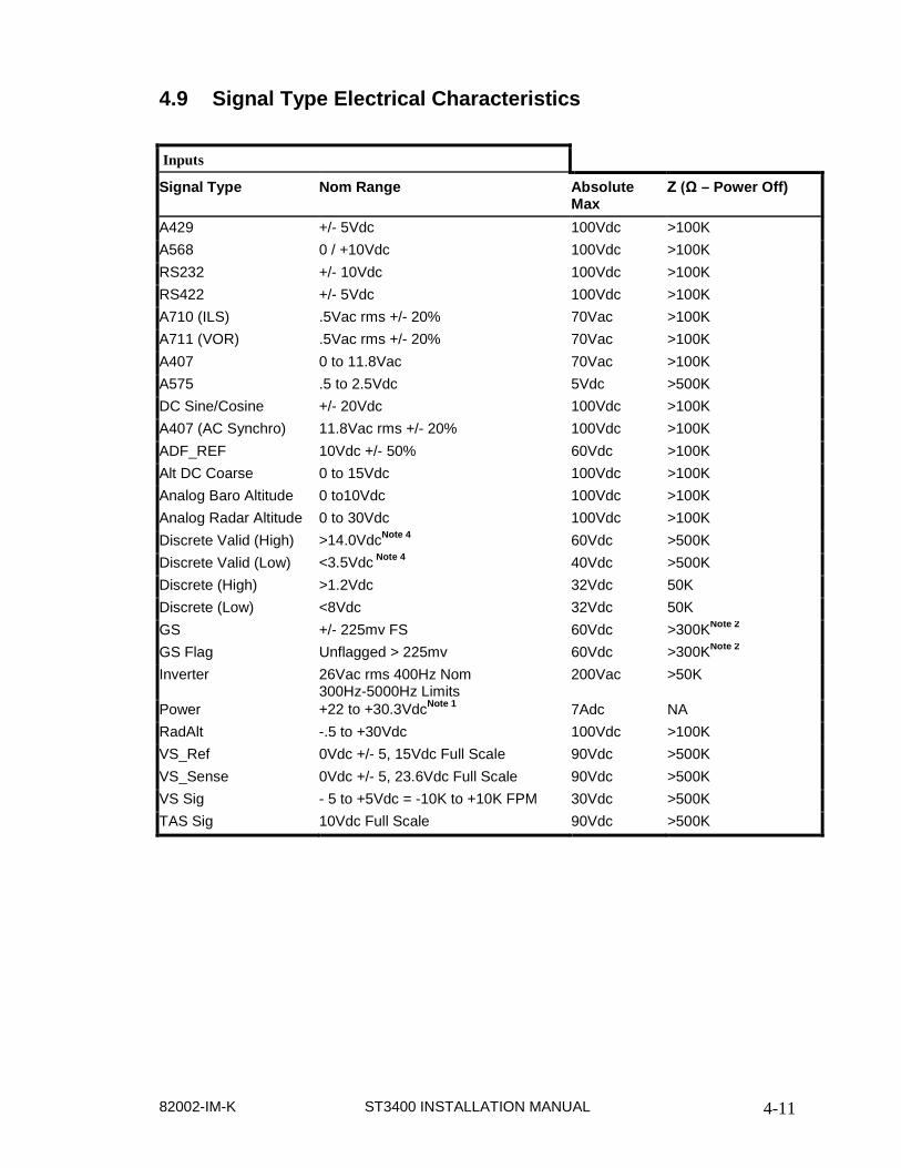
4.9 Signal Type Electrical Characteristics
Inputs
Signal Type Nom Range Absolute Max
Z (Ω – Power Off)
A429 +/- 5Vdc 100Vdc >100K A568 0 / +10Vdc 100Vdc >100K RS232 +/- 10Vdc 100Vdc >100K RS422 +/- 5Vdc 100Vdc >100K A710 (ILS) .5Vac rms +/- 20% 70Vac >100K A711 (VOR) .5Vac rms +/- 20% 70Vac >100K A407 0 to 11.8Vac 70Vac >100K A575 .5 to 2.5Vdc 5Vdc >500K DC Sine/Cosine +/- 20Vdc 100Vdc >100K A407 (AC Synchro) 11.8Vac rms +/- 20% 100Vdc >100K ADF_REF 10Vdc +/- 50% 60Vdc >100K Alt DC Coarse 0 to 15Vdc 100Vdc >100K Analog Baro Altitude 0 to10Vdc 100Vdc >100K Analog Radar Altitude 0 to 30Vdc 100Vdc >100K Discrete Valid (High) >14.0VdcNote 4 60Vdc >500K Discrete Valid (Low) <3.5Vdc Note 4 40Vdc >500K Discrete (High) >1.2Vdc 32Vdc 50K Discrete (Low) <8Vdc 32Vdc 50K GS +/- 225mv FS 60Vdc >300KNote 2 GS Flag Unflagged > 225mv 60Vdc >300KNote 2 Inverter 26Vac rms 400Hz Nom
300Hz-5000Hz Limits 200Vac >50K
Power +22 to +30.3VdcNote 1 7Adc NA RadAlt -.5 to +30Vdc 100Vdc >100K VS_Ref 0Vdc +/- 5, 15Vdc Full Scale 90Vdc >500K VS_Sense 0Vdc +/- 5, 23.6Vdc Full Scale 90Vdc >500K VS Sig - 5 to +5Vdc = -10K to +10K FPM 30Vdc >500K TAS Sig 10Vdc Full Scale 90Vdc >500K

4-12 ST3400 INSTALLATION MANUAL 82002-IM-K
Signal Type Electrical Characteristics (cont.) Outputs
Signal Type Nom Range AbsoluteNote 3 Max
Load (Ω)
A429 +/- 5Vdc 70mAdc 2K (Minimum) RS232 +/- 5Vdc 70mAdc 500 (Minimum) A575 3.54 mA +/-1% 25mA 500 Audio Output (LL) 0 to 27.2Vpk-pk 27.2Vpk-pk 600
Audio Output (Spkr) 0 to 4 Watts Max RMS into 8 ohms 16V pk-pk 8 (inductive) Open Drain 1Ω or High Impedance (over current
protected) 250mAdc >350K
Notes:
1. At +28Vdc, nominal current is 1.4Adc +/- 5%, 1 minute after start up.
2. Power On Load = 60.4K. For Glideslope there may need to be a 1K load somewhere else in the system to meet the receiver load requirements. Check installation instructions for the interfaced receiver.
3. Outputs are protected against shorts to ground. Shorts to power supply may cause damage to components.
4. Discrete inputs actively pulled to 27.5v through 30k ohms when selected ‘active low’ or actively pulled to 0v through 30k ohms when selected ‘active high’ in the maintenance pages. This ensures the input is in the ‘inactive’ state if an external connection fails. If interfacing to discrete signals which do not supply a “hard” 0v/27.5 volt transition, any input network may be used that ensures that the discrete input pin is not within 1.0v from its nominal threshold shown in the table either in the active or inactive state.

82002-IM-K ST3400 INSTALLATION MANUAL 5-1
5 MAINTENANCE MODE
5.1 Normal Mode Operation Unless the system is started up in “maintenance mode”, it will automatically power-up in “Normal” flight operations mode.
5.2 Maintenance Mode To access the Maintenance Mode, prior to applying power to the system, press and hold the [BRG 1] [BRG 2] selection buttons then apply power and wait until the Maintenance Index page is displayed. Then release these buttons.
From the maintenance mode the system normal operations can be accessed by holding the “M” button for approximately 3 seconds. This feature can be used to test or see the results of a change in maintenance page configuration. The maintenance pages can be brought back by holding the “M” button again for 3 seconds.
NOTE: WHEN DOING A FINAL TEST OF A SYSTEM MAKE SURE THE POWER HAS BEEN RECYCLED TO VERIFY CORRECT SETTINGS.
To exit the maintenance mode for normal flight operations turn off the power for 15 seconds and restart the unit normally.

5-2 ST3400 INSTALLATION MANUAL 82002-IM-K
THIS PAGE INTENTIONALLY LEFT BLANK
82002-IM-K ST3400 INSTALLATION MANUAL 6-1
6 SETUP PROCEDURES
6.1 General Setup procedures for the ST3400 are accessed and addressed through the Maintenance Mode.
6.1.1 Accessing Maintenance Pages
The Maintenance Mode allows the operator to read and edit the factory settings and the configuration data associated with a unit. The system will use this information to configure its internal/external interfaces appropriately and save the information to a configuration file.
The first maintenance page is the Maintenance Index., This page provides a list of the subsequent pages. The maintenance index menu lists the number and title for each maintenance page.
The maintenance pages operate in either “READ” or “EDIT” mode. Read mode write-protects the configuration data. Pressing the [MODE] softkey in the maintenance index will change the mode to “EDIT” which removes the write-protection and allows changing any configuration item.
6.1.2 Uploading Data or System Software
The Windows based ST3400 TAWS Loader program is used to transfer terrain data, airport data, , and configuration data to the TAWS equipment memory. The Loader communicates with the ST3400 unit via the USB Port located in the lower right corner of the front bezel.
The Loader runs on a personal computer with a USB port and Microsoft Windows 98, Windows Me, Windows 2000, or Windows XT software.
The applicable Windows Driver, Loader executable, and instructions are supplied with the software or data. The Loader only operates when in maintenance mode. NOTE: As a convenience to identification System Software for units with MOD-A is marked with an ‘A’ prefix. For example, software 3.05 loads into a non MOD-A unit; software A3.05 loads into a MOD-A unit. The “A” prefix is not a significant digit in the software part number or in the software certification, i.e. A3.05 and 3.05 are considered identical for the purpose of conformity. Incompatible software is automatically detected by the Loader and will not load.
6.1.3 Configuration Module
The Configuration Module (CM) stores installation configurations. The physical Configuration Module is directly mounted to the rear of the instrument. Configuration module can be used when replacing an existing ST3400. Data stored in the configuration module can be copied directly to the replacement unit.

6-2 ST3400 INSTALLATION MANUAL 82002-IM-K
6.1.4 Configuration Module Status Page
“CONFIG MODULE STATUS” page may appear during initial turn on and programming of a unit. This page will only appear again if there is a mismatch between the configuration information saved in the Configuration Module and the ST3400. The mismatch identified with the configuration information is shown at the top of this page, along with the actions that may be taken.
The options displayed on the “CONFIG MODULE STATUS” page are as follows.
“DISABLE CM” (CM) When this option is selected no stored data will be read from or written to the Configuration Module. Selecting “Disable CM” will allow the installer to go directly to the Maintenance Index page 1.
Note “CM” will appear in the upper right corner to indicate that the configuration module is not operational.
“ST3400 TO CM”: Selecting this option will allow stored ST3400 configuration data to be written to the configuration module and stored.
NOTE: When selecting this option ST3400 configuration data will be written TO the configuration module and overwrite any existing configuration data in the Configuration Module.
“CM TO ST3400”: Selecting this option will allow stored Configure Module data to be written to the ST3400.
NOTE: When selecting this option data FROM the configuration module will overwrite any existing configuration data in the ST3400. The configuration module is unaffected.
6.1.5 Tail Number
As part of the configuration, an aircraft identifier (Tail Number) should be entered on the systems settings page.

82002-IM-K ST3400 INSTALLATION MANUAL 6-3
6.2 Maintenance Index Page The Maintenance Index page (see Figure 6-1) is a multiple–choice list that provides an index of all other maintenance pages and allows the operator to jump to a particular page. First scroll the Cursor to point to the desired maintenance page listing using the [Up] Soft key or [Down] Soft key. The [SELECT] Soft key is then pressed to jump to this page. Once in the Maintenance pages, press the [OPER] Soft key to return to the Maintenance Index page. The [PREV] or [NEXT] Soft keys may also be used to reach a particular maintenance page sequentially.
Figure 6-1: Maintenance Index Page Display
6.2.1 Maintenance Page Number/Title
The Maintenance Page Number/Title is displayed on every maintenance page showing the maintenance page number and title.
6.2.2 Cursor
The Cursor points to the item, which may be modified or selected. If there are no selectable items on the currently displayed maintenance page, the Current Line Indicator is not displayed.
The [UP] Soft key and [DOWN] Soft key are used to move the Cursor up and down through the list.

6-4 ST3400 INSTALLATION MANUAL 82002-IM-K
6.2.3 Soft Keys
The Soft Keys (see Table 6-1) are labeled to convey the context sensitive function of each button as required.
Table 6-1: Common Maintenance Page Soft Keys
MAINTENANCE PAGE SOFT KEYS
DISPLAY INTERFACE
Name Description
Previous Page PREV Returns to the prior maintenance page; if the first maintenance page is being displayed, moves to the last maintenance page.
The Maintenance Page Number/Title indicates the current maintenance page.
Next Page NEXT Advances to the next maintenance page; if the last maintenance page is being displayed, then moves to the first maintenance page.
The Maintenance Page Number/Title indicates the current maintenance page.
Select Page SELECT From the index page, jump directly to the indicated page.
Operation OPER From a maintenance page, if pressed once, will jump to Maintenance Index page. If pressed and held in, will transition into the Flight Operations displays.
Maintenance MAINT From a flight operations page, return to the Maintenance Index page. The Cursor will point to the maintenance page listing that was displayed prior to transitioning to the Flight Operations Test displays.
Scroll Up UP Moves the Cursor to the previous selectable item.
Hold key down to automatically repeat.
If there are no selectable items, key is disabled.
Scroll Down DOWN Scrolls the Current Line Indicator to the next selectable item.
Hold key down to automatically repeat.
If there are no selectable items, key is disabled.
Value/Model-Type Toggle
VALUE Provides access to read secondary data from a piece of equipment.. The [DOWN]/[UP] soft keys will scroll through each Data Value that is available. If no secondary data is present, the Soft key is not displayed.
Type Toggle TYPE Returns function of [DOWN]/[UP] soft keys back from value selection monitoring into Type selection.
Model Toggle MODEL Returns function of [DOWN]/[UP] soft keys back from value selection monitoring into Model selection.
Read/Edit Enable MODE
Change the edit/read mode for all maintenance pages. Only displayed from the maintenance index page. Press to toggle the write-protection of the configuration data.
Decrement (-) If the maintenance item is a numeric value, this key will decreases the value; if a multiple-choice entry then will move to the previous choice.
Hold to repeat.

82002-IM-K ST3400 INSTALLATION MANUAL 6-5
MAINTENANCE PAGE SOFT KEYS
DISPLAY INTERFACE
Name Description
Increment (+) If the maintenance item is a numeric value, this key increases the value; if the maintenance item is a multiple-choice entry then it is used to move to the next choice.
Hold to repeat.
6.2.4 Edit/Read Mode Indicator
The Edit/Read Mode shows the state of the configuration write protection.
6.2.5 How to Access Maintenance Pages
The Maintenance Index shows all maintenance pages and allows the operator to jump directly to any other maintenance page by the use of Soft keys.
6.2.5.1 Access the Maintenance Index page
Prior to applying power to the system:
Press and hold the [BRG 1] [BRG 2] selection buttons until the Maintenance Index page is displayed.
6.2.5.2 Jump to a specific page
Press the [UP] Soft key or the [DOWN] softkey to move the Cursor.
Press the [SELECT] Soft key to jump to this page.
6.2.5.3 Step Through Pages
Press the [PREV] or [NEXT] soft key.

6-6 ST3400 INSTALLATION MANUAL 82002-IM-K
6.3 Maintenance Pages The sections that follow illustrate maintenance pages and describe each maintenance page and it’s contents. Maintenance pages may have names, indicators, readouts, lists, entries, and/or requests. A name is a text string that identifies a page or item. A Readout consists of value(s) and/or text string(s) that provide the status of an item. A multiple-choice list consists of a set of selectable items/choices where the set is shown with each item/choice on a separate line. A multiple-choice entry is an item with a set of selectable choices where the set is shown one choice at a time on a single line. A request is used to test a system function or to reset internal values.
6.3.1 System Maintenance Page
The System page (see Figure 6-2) provides information that identifies this unit and this unit’s hardware/software.
The modifiable values (Aircraft Type through FLTA Alert Type) show the overall configuration for the unit and allow the operator to change these items.
Figure 6-2: System (Edit Mode)
6.3.1.1 Item
An Item identifies each maintenance item.

82002-IM-K ST3400 INSTALLATION MANUAL 6-7
6.3.1.2 Editable Value
An Editable Value is an item whose value may be changed directly by the operator when the maintenance pages are in the edit mode. They are shown in RED. The Cursor points to the maintenance item to be modified. The [+]/[-] Soft Keys are used to change the value or scroll through the possible choices.
When the maintenance pages are in the read mode the operator can see but cannot change the items.
6.3.1.3 Internal Value
Internal Values are items shown for reference which cannot be edited. They are shown in GRN or YEL.
6.3.2 Air Data Page
The Air Data page (see Figure 6-3) contains the setup information for the #1 and #2 airdata systems. Use the [UP] or [DOWN] Softkeys to select a setup item. This will move the Cursor to the appropriate line and display the current input data value, input voltage (if applicable) and pin-pairs of the selected signal.
CBA: Corrected Baro Altitude Input BR: Baro Rate input (Vertical Speed) TA: True Airspeed
Figure 6-3: Air Data

6-8 ST3400 INSTALLATION MANUAL 82002-IM-K
6.3.3 ADF & HDG Page
The ADF & HDG page (see Figure 6-4) contains the setup information for the #1 and #2 ADF receivers (for RMI use) and #1 and #2 HDG systems. Use the [UP] or [DOWN] Softkeys to select a setup item. This will move the Cursor to the appropriate line and display the current input data value, input voltage (if applicable) and pin-pairs of the selected signal.
ADF: ADF receiver HDG: HDG system
When selecting analog inputs, a VALID select will be present. If no valid signal is available for the interconnected equipment, set this to NONE which will treat the signal inputs as always valid. If a VALID signal is available, set appropriately to VALID HIGH or VALID LOW. The effect of these settings will be immediately shown at a VALID or INVALID data value at the top of the screen
Figure 6-4: ADF & HDG

82002-IM-K ST3400 INSTALLATION MANUAL 6-9
6.3.4 Discretes Maintenance Page
The Discretes page (see Figure 6-5) shows all the discrete inputs.
A Discrete may be VALID-LOW or VALID-HIGH. In either case a 30K resistor is connected to pull the signal to the invalid state (ground or aircraft power) as applicable unless the valid signal is applied.
Figure 6-5: DISCRETES

6-10 ST3400 INSTALLATION MANUAL 82002-IM-K
6.3.5 NAV and ILS Page
The NAV and ILS page (see Figure 6-6) selects the configuration of NAV receiver and Glideslope receiver inputs. When the NAV input is selected to 429, the glideslope uses the same 429 port as the NAV. When analog, these two signals are selected separately.
The 429 data stream for NAV BRG can be selected TO VOR or FROM VOR. Set as appropriate for the receiver in use.
Once a selection is made, the port configuration for NAV will be automatically made based on the selection chosen and data will appear in the data VALUE area.
The data VALUE shows only a single data item. This page has an additional softkey labeled [VALUE] which can be used to scroll through all of the NAV and ILS data coming from the receiver. Use the [UP]/[DOWN] Soft keys to scroll through the various data items. Press the [TYPE] Soft key to exit the "Value" scroll function.
When the NAV input is analog composite, both the VOR bearing and the LOC deviation are demodulated from the analog data. The LOC deviation is used to qualify the GS data in addition to the analog GS flag.
Back Course (from the HSI) discrete input may be VALID-LOW or VALID-HIGH. This is used to inhibit the Glideslope alert GPWS mode 5.
Figure 6-6: NAV and ILS

82002-IM-K ST3400 INSTALLATION MANUAL 6-11
6.3.6 RADALT Maintenance Page
The RADALT page (see Figure 6-7) selects the configuration of radar altimeter inputs. If no radar altimeters are installed set configuration of RA1 and RA2 to NONE.
Radar altimeters are selected by equipment type, i.e. ALT55 for Collins ALT55 altimeter, etc.
Once the equipment is selected, the radar altitude can be read from the data VALUE line to check for correct operation.
For analog inputs, a corresponding VALID input is present. Ensure that this item is VALID during normal operation and INVALID during TEST of the RA or when the RA is powered off.
Note: For Analog radar altimeters, mis-setting the Radar altimeter selection may show a correct value below 500’ and an incorrect value above 500’. Therefore, if any troubleshooting is required regarding Radar Altimeter operation it is suggested that a test flight be performed in VFR conditions and the Radar Altitude be monitored on the ST3400 maintenance page simultaneously with the Radar Altimeter indicator to check for correct operation.
The Decision Height (D HGT) discrete input may be VALID-LOW or VALID-HIGH. This will produce a ‘MINIMUMS’ audio callout.
Figure 6-7: RADALT

6-12 ST3400 INSTALLATION MANUAL 82002-IM-K
6.3.7 GPS/FMS
There are two GPS/FMS pages (see Figure 6-8) for selection of Primary and Secondary receivers respectively.
The multiple–choice list allows the operator to specify the type of GPS/FMS connected to the primary GPS/FMS port. Select the desired receiver using the [UP]/[DOWN] Soft keys and use the [SET] softkey to make the selection.
Once a selection is made, the port configuration for FMS will be automatically made based on the selection chosen and data will appear in the data VALUE area.
The data VALUE shows only a single data item. This page has an additional softkey labeled VALUE which can be used to scroll through all of the GPS/FMS DATA coming from the receiver. Use the [UP]/[DOWN] Soft keys to scroll through the various data items. Press the [MODEL] Soft key to exit the "Value" scroll function.
Figure 6-8: GPS/FMS 1 Select Maintenance Page (typical)
6.3.7.1 More Indicator
The More Indicator (see Figure 6-8) indicates more choices than the listings currently displayed on the screen. An arrow pointing down indicates that more choices exist below the last listing currently being displayed.

82002-IM-K ST3400 INSTALLATION MANUAL 6-13
6.3.8 TCAS
The TCAS page (see Figure 6-9) shows selections available for Traffic.
The multiple–choice list allows the operator to specify the type of Traffic processor connected to the Traffic port. Select using the [UP]/[DOWN] Soft keys and use the [SET] softkey to make the selection.
Once a selection is made, the port configuration for Traffic will be automatically made based on the selection chosen and data will appear in the data VALUE area.
This page has an additional softkey labeled VALUE which can be used to scroll through all of the TCAS DATA coming from the processor. Use the [UP]/[DOWN] Soft keys to scroll through the various data items. Press the [MODEL] Soft key to exit the "Value" scroll function.
If a ST3400 in the field is being upgraded to display Traffic, please contact the factory for a software key necessary to enable the traffic display. The Traffic key can be entered on this screen manually. Software 3.00 and above is required to display traffic.
Figure 6-9: TCAS Select Maintenance Page (typical)
6.3.8.1 More Indicator
The More Indicator (see Figure 6-9) indicates more choices than the listings currently displayed on the screen. An arrow pointing down indicates that more choices exist below the last listing currently being displayed.

6-14 ST3400 INSTALLATION MANUAL 82002-IM-K
6.3.9 Status Page
The Status page (see Figure 6-9) shows a composite status of all the ST3400 inputs.
Figure 6-9: STATUS

82002-IM-K ST3400 INSTALLATION MANUAL 6-15
6.3.10 Callouts
The Callouts page (see Figure 6-10) allows enabling Radar Altitude autio callouts. Use the [UP] or [DOWN] Softkeys to select a setup item, this will move the Cursor to the appropriate line. [+] and [-] select “ON” or “OFF for each callout.
Radar Altimeter input is required for the Callouts to function.
Figure 6-10: CALLOUTS

7-16 ST3400 INSTALLATION MANUAL 82002-IM-K
7 POST INSTALLATION
7.1 General Post Installation testing and diagnostic procedures are accessed and addressed through the Maintenance Interface.
7.1.1 Accessing Maintenance Pages
The Maintenance Interface allows the operator access to information pages.
The Maintenance Index page provides a menu that lists all accessible maintenance pages. The maintenance index menu lists the number and title for each maintenance page.
The Maintenance Interface can only be accessed during the system power-up sequence. Before applying power to the system, the operator must press and hold a combination of selection buttons. Exiting the maintenance pages completely must be done via a power down / power up sequence.
The interface with the operator is in the read mode upon initial entry into the maintenance pages. In the read mode all configuration values are read-only. To make changes, the edit/read mode must be changed to edit.
7.1.1.1 Access the Maintenance Index page
Prior to applying power to the system:
Press and hold the [BRG 1] [BRG 2] selection buttons until the Maintenance Index page is displayed.
7.1.1.2 Quickly access a specific page
Press the [UP] Soft key or the [DOWN] Soft key to move the Cursor.
Press the button labeled [SELECT] Soft key to display the page pointed to by the Cursor.
or
Press Indicator or press the [PREV] soft key or the [NEXT] soft key.
7.1.1.3 Quickly return to the Maintenance Index page
Once any other maintenance page has been selected, for quick access to the Maintenance Index page:
Press the [OPER] Soft key if with in the Maintenance pages or, press and hold the [MAINT] Soft key if in the Flight Operation Display. Since these two soft keys are the same physical button, this quick access sequence is done by pressing the button twice.

82002-IM-K ST3400 INSTALLATION MANUAL 7-17
7.2 Post Installation Testing
7.2.1 Power-On Self-Test
The Power-On Self-Test capability is an automatic test of equipment condition. It executes during the power-up sequence and reports any internal errors via on-screen readouts. The failure of the display itself is a major failure and will result in the inability to show further system-level error messages.
7.2.2 ST3400 TAWS/RMI
Verify DC Power, AC Power and Ground inputs to the Sandel ST3400 TAWS/RMI J1, J2 and J3 connectors before installing Sandel TAWS/RMI ST3400.
7.2.3 Install Sandel ST3400 TAWS/RMI into aircraft
Enter the maintenance mode by depressing “BRG1 & BRG2” and apply power to the unit.
7.2.4 Record the following Aircraft Configuration
Aircraft S/N: __________________Aircraft Registration: __________ Aircraft Make: ________________ Aircraft Model: __________
7.2.5 Record the following system information:
Date: ______________________________
ST3400 SN: ________________________ ST3400 PN: ________________________
ST3400 Software Rev: ________________
ST3400 Terrain Rev: _________________
ST3400 Map Data Rev: _______________
7.2.6 Required Test Equipment:
1. Pitot Static Test Box
2. VOR/ILS Ramp Test Set
3. Digital Multimeter
4. Radar Altimeter Test Press to Test button, or Radar Altimeter Test Set
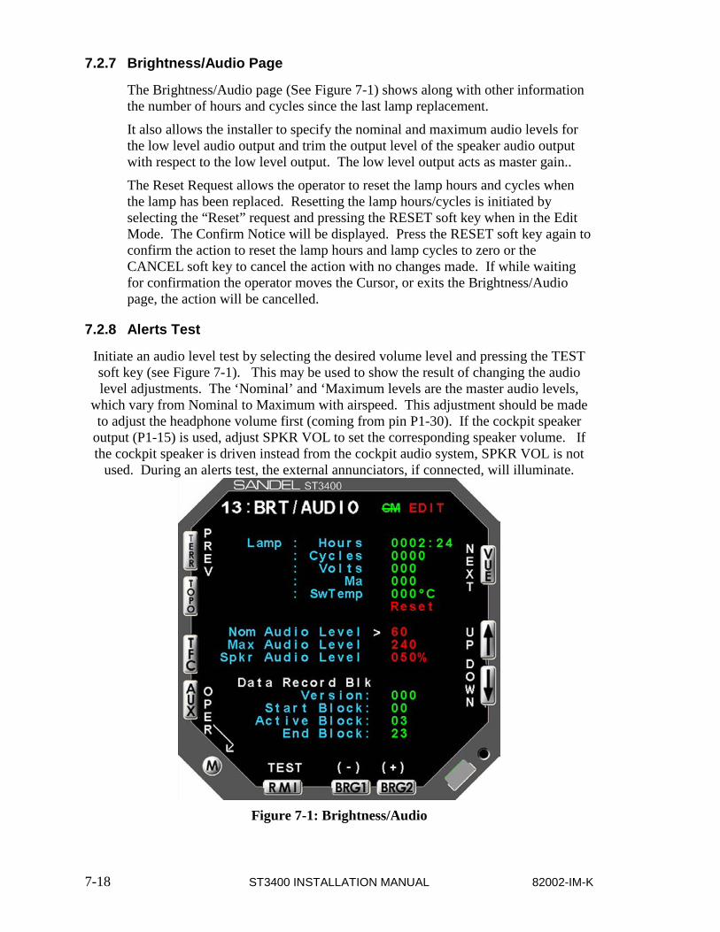
7-18 ST3400 INSTALLATION MANUAL 82002-IM-K
7.2.7 Brightness/Audio Page
The Brightness/Audio page (See Figure 7-1) shows along with other information the number of hours and cycles since the last lamp replacement.
It also allows the installer to specify the nominal and maximum audio levels for the low level audio output and trim the output level of the speaker audio output with respect to the low level output. The low level output acts as master gain..
The Reset Request allows the operator to reset the lamp hours and cycles when the lamp has been replaced. Resetting the lamp hours/cycles is initiated by selecting the “Reset” request and pressing the RESET soft key when in the Edit Mode. The Confirm Notice will be displayed. Press the RESET soft key again to confirm the action to reset the lamp hours and lamp cycles to zero or the CANCEL soft key to cancel the action with no changes made. If while waiting for confirmation the operator moves the Cursor, or exits the Brightness/Audio page, the action will be cancelled.
7.2.8 Alerts Test
Initiate an audio level test by selecting the desired volume level and pressing the TEST soft key (see Figure 7-1). This may be used to show the result of changing the audio level adjustments. The ‘Nominal’ and ‘Maximum levels are the master audio levels,
which vary from Nominal to Maximum with airspeed. This adjustment should be made to adjust the headphone volume first (coming from pin P1-30). If the cockpit speaker
output (P1-15) is used, adjust SPKR VOL to set the corresponding speaker volume. If the cockpit speaker is driven instead from the cockpit audio system, SPKR VOL is not
used. During an alerts test, the external annunciators, if connected, will illuminate.
Figure 7-1: Brightness/Audio
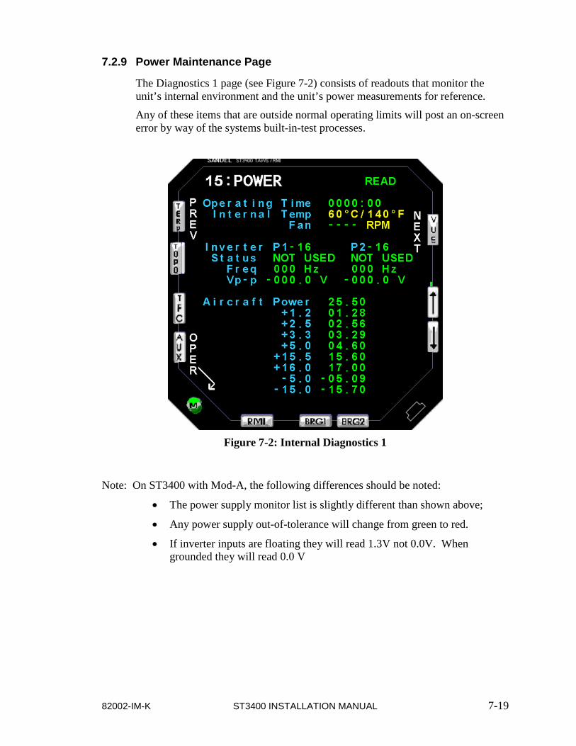
82002-IM-K ST3400 INSTALLATION MANUAL 7-19
7.2.9 Power Maintenance Page
The Diagnostics 1 page (see Figure 7-2) consists of readouts that monitor the unit’s internal environment and the unit’s power measurements for reference.
Any of these items that are outside normal operating limits will post an on-screen error by way of the systems built-in-test processes.
Figure 7-2: Internal Diagnostics 1
Note: On ST3400 with Mod-A, the following differences should be noted:
• The power supply monitor list is slightly different than shown above;
• Any power supply out-of-tolerance will change from green to red.
• If inverter inputs are floating they will read 1.3V not 0.0V. When grounded they will read 0.0 V
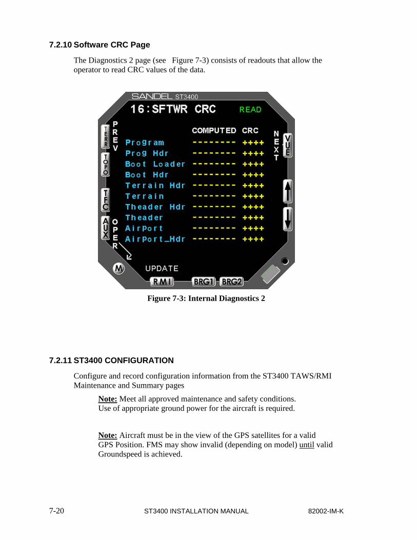
7-20 ST3400 INSTALLATION MANUAL 82002-IM-K
7.2.10 Software CRC Page
The Diagnostics 2 page (see Figure 7-3) consists of readouts that allow the operator to read CRC values of the data.
Figure 7-3: Internal Diagnostics 2
7.2.11 ST3400 CONFIGURATION
Configure and record configuration information from the ST3400 TAWS/RMI Maintenance and Summary pages
Note: Meet all approved maintenance and safety conditions. Use of appropriate ground power for the aircraft is required.
Note: Aircraft must be in the view of the GPS satellites for a valid GPS Position. FMS may show invalid (depending on model) until valid Groundspeed is achieved.

82002-IM-K ST3400 INSTALLATION MANUAL 7-21
RECORD ST3400 TAWS/RMI CONFIGURATION
PAGE EQUIPMENT FUNCTION DATA TYPE
AIR DATA ADC-1
3 CBA1
3 BR1
3 TA1
3 OAT
AIR DATA ADC-2
4 CBA1
4 BR1
4 TA1
OAT
ADF & HEADING
5 ADF-1
5 VALID
5 ADF-2
5 VALID
5 HDG-1
5 VALID
5 HDG-2
5 VALID
DISCERTES
6 AP
6 ALERT
6 TEST
6 FLAPS
6 GEAR
6 WHEELS
6 WINDSHILD
WIPERS

7-22 ST3400 INSTALLATION MANUAL 82002-IM-K
PAGE EQUIPMENT FUNCTION DATA TYPE
NAV & ILS
7 NAV-1
7 CALIBRATE
7 NAV-2
7 CALIBRATE
7 GS NO 1
7 GS NO 2
7 Back Course
RADIO ALTIMETER
8 RA-1
8 VALID
8 Decision Height
GPS/FMS-1
9 SELECTION
GPS/FMS-2
10 SELECTION
TRAFFIC
11 SELECTION
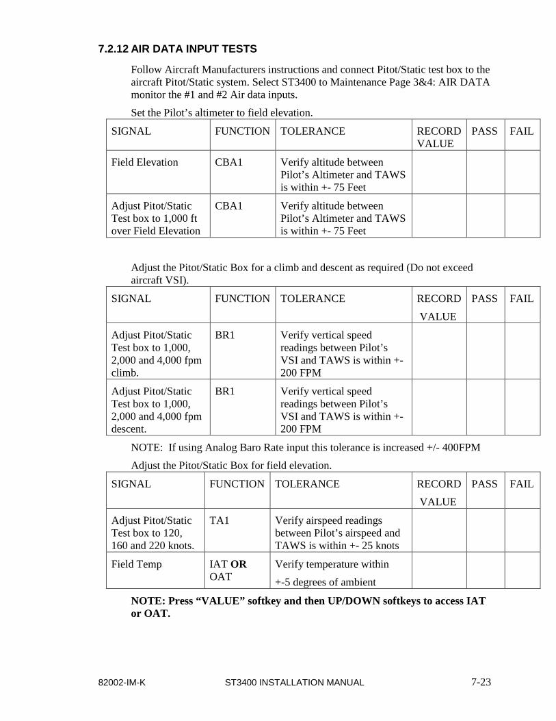
82002-IM-K ST3400 INSTALLATION MANUAL 7-23
7.2.12 AIR DATA INPUT TESTS
Follow Aircraft Manufacturers instructions and connect Pitot/Static test box to the aircraft Pitot/Static system. Select ST3400 to Maintenance Page 3&4: AIR DATA monitor the #1 and #2 Air data inputs.
Set the Pilot’s altimeter to field elevation.
SIGNAL FUNCTION TOLERANCE RECORD VALUE
PASS FAIL
Field Elevation CBA1 Verify altitude between Pilot’s Altimeter and TAWS is within +- 75 Feet
Adjust Pitot/Static Test box to 1,000 ft over Field Elevation
CBA1 Verify altitude between Pilot’s Altimeter and TAWS is within +- 75 Feet
Adjust the Pitot/Static Box for a climb and descent as required (Do not exceed aircraft VSI).
SIGNAL FUNCTION TOLERANCE RECORD
VALUE
PASS FAIL
Adjust Pitot/Static Test box to 1,000, 2,000 and 4,000 fpm climb.
BR1 Verify vertical speed readings between Pilot’s VSI and TAWS is within +- 200 FPM
Adjust Pitot/Static Test box to 1,000, 2,000 and 4,000 fpm descent.
BR1 Verify vertical speed readings between Pilot’s VSI and TAWS is within +- 200 FPM
NOTE: If using Analog Baro Rate input this tolerance is increased +/- 400FPM
Adjust the Pitot/Static Box for field elevation.
SIGNAL FUNCTION TOLERANCE RECORD
VALUE
PASS FAIL
Adjust Pitot/Static Test box to 120, 160 and 220 knots.
TA1 Verify airspeed readings between Pilot’s airspeed and TAWS is within +- 25 knots
Field Temp IAT OR OAT
Verify temperature within
+-5 degrees of ambient
NOTE: Press “VALUE” softkey and then UP/DOWN softkeys to access IAT or OAT.
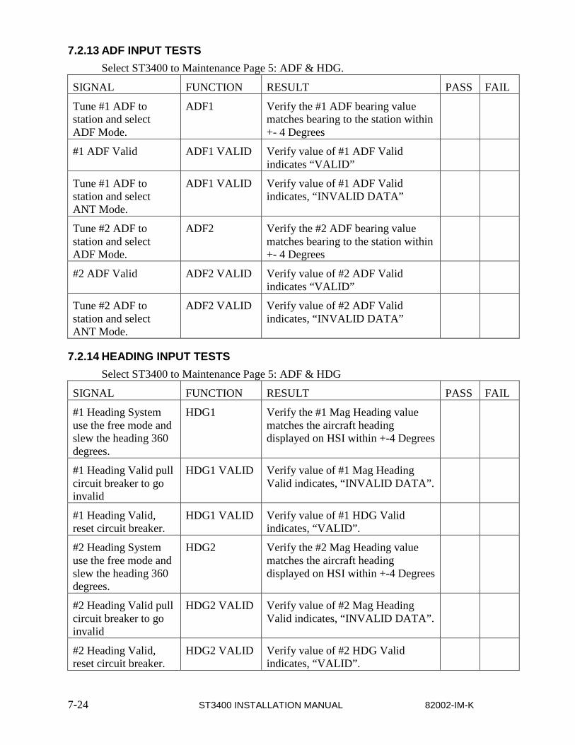
7-24 ST3400 INSTALLATION MANUAL 82002-IM-K
7.2.13 ADF INPUT TESTS Select ST3400 to Maintenance Page 5: ADF & HDG.
SIGNAL FUNCTION RESULT PASS FAIL
Tune #1 ADF to station and select ADF Mode.
ADF1 Verify the #1 ADF bearing value matches bearing to the station within +- 4 Degrees
#1 ADF Valid ADF1 VALID Verify value of #1 ADF Valid indicates “VALID”
Tune #1 ADF to station and select ANT Mode.
ADF1 VALID Verify value of #1 ADF Valid indicates, “INVALID DATA”
Tune #2 ADF to station and select ADF Mode.
ADF2 Verify the #2 ADF bearing value matches bearing to the station within +- 4 Degrees
#2 ADF Valid ADF2 VALID Verify value of #2 ADF Valid indicates “VALID”
Tune #2 ADF to station and select ANT Mode.
ADF2 VALID Verify value of #2 ADF Valid indicates, “INVALID DATA”
7.2.14 HEADING INPUT TESTS Select ST3400 to Maintenance Page 5: ADF & HDG
SIGNAL FUNCTION RESULT PASS FAIL
#1 Heading System use the free mode and slew the heading 360 degrees.
HDG1 Verify the #1 Mag Heading value matches the aircraft heading displayed on HSI within +-4 Degrees
#1 Heading Valid pull circuit breaker to go invalid
HDG1 VALID Verify value of #1 Mag Heading Valid indicates, “INVALID DATA”.
#1 Heading Valid, reset circuit breaker.
HDG1 VALID Verify value of #1 HDG Valid indicates, “VALID”.
#2 Heading System use the free mode and slew the heading 360 degrees.
HDG2 Verify the #2 Mag Heading value matches the aircraft heading displayed on HSI within +-4 Degrees
#2 Heading Valid pull circuit breaker to go invalid
HDG2 VALID Verify value of #2 Mag Heading Valid indicates, “INVALID DATA”.
#2 Heading Valid, reset circuit breaker.
HDG2 VALID Verify value of #2 HDG Valid indicates, “VALID”.
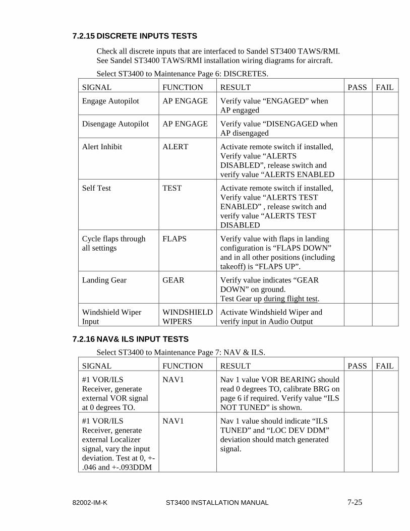
82002-IM-K ST3400 INSTALLATION MANUAL 7-25
7.2.15 DISCRETE INPUTS TESTS
Check all discrete inputs that are interfaced to Sandel ST3400 TAWS/RMI. See Sandel ST3400 TAWS/RMI installation wiring diagrams for aircraft.
Select ST3400 to Maintenance Page 6: DISCRETES.
SIGNAL FUNCTION RESULT PASS FAIL
Engage Autopilot AP ENGAGE Verify value “ENGAGED” when AP engaged
Disengage Autopilot AP ENGAGE Verify value “DISENGAGED when AP disengaged
Alert Inhibit ALERT Activate remote switch if installed, Verify value “ALERTS DISABLED”, release switch and verify value “ALERTS ENABLED
Self Test TEST Activate remote switch if installed, Verify value “ALERTS TEST ENABLED” , release switch and verify value “ALERTS TEST DISABLED
Cycle flaps through all settings
FLAPS Verify value with flaps in landing configuration is “FLAPS DOWN” and in all other positions (including takeoff) is “FLAPS UP”.
Landing Gear GEAR Verify value indicates “GEAR DOWN” on ground. Test Gear up during flight test.
Windshield Wiper Input
WINDSHIELD WIPERS
Activate Windshield Wiper and verify input in Audio Output
7.2.16 NAV& ILS INPUT TESTS Select ST3400 to Maintenance Page 7: NAV & ILS.
SIGNAL FUNCTION RESULT PASS FAIL
#1 VOR/ILS Receiver, generate external VOR signal at 0 degrees TO.
NAV1 Nav 1 value VOR BEARING should read 0 degrees TO, calibrate BRG on page 6 if required. Verify value “ILS NOT TUNED” is shown.
#1 VOR/ILS Receiver, generate external Localizer signal, vary the input deviation. Test at 0, +-.046 and +-.093DDM
NAV1 Nav 1 value should indicate “ILS TUNED” and “LOC DEV DDM” deviation should match generated signal.
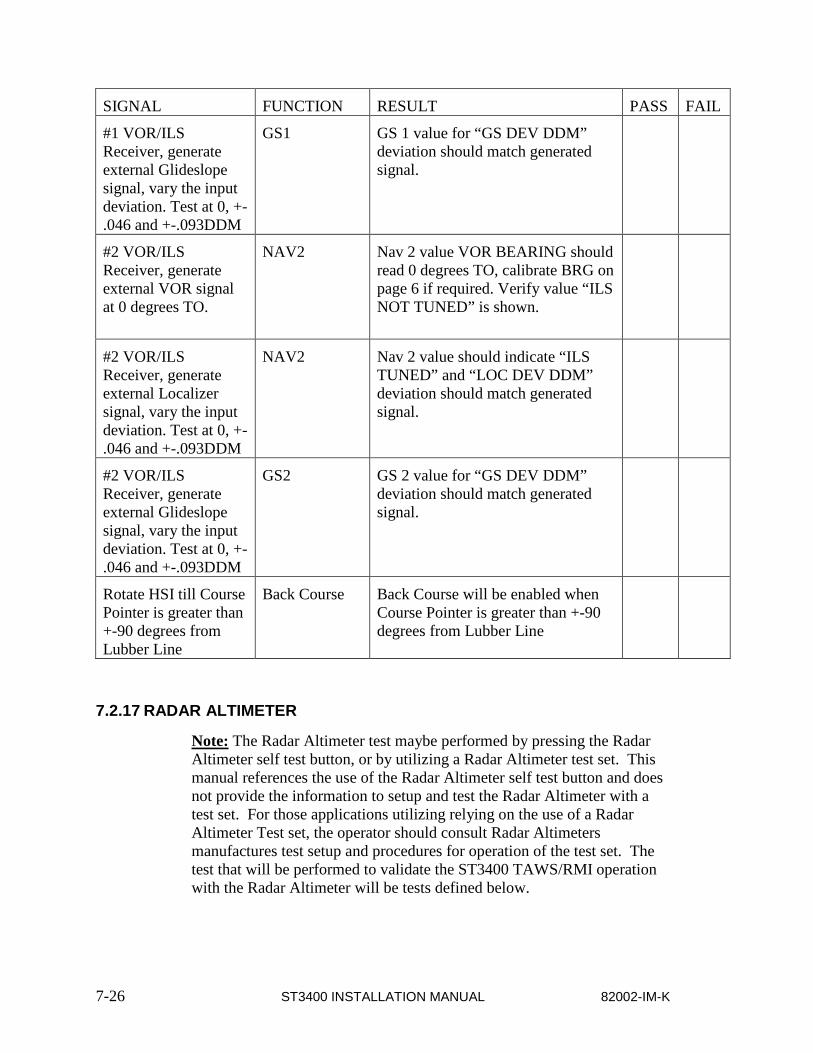
7-26 ST3400 INSTALLATION MANUAL 82002-IM-K
SIGNAL FUNCTION RESULT PASS FAIL
#1 VOR/ILS Receiver, generate external Glideslope signal, vary the input deviation. Test at 0, +-.046 and +-.093DDM
GS1 GS 1 value for “GS DEV DDM” deviation should match generated signal.
#2 VOR/ILS Receiver, generate external VOR signal at 0 degrees TO.
NAV2 Nav 2 value VOR BEARING should read 0 degrees TO, calibrate BRG on page 6 if required. Verify value “ILS NOT TUNED” is shown.
#2 VOR/ILS Receiver, generate external Localizer signal, vary the input deviation. Test at 0, +-.046 and +-.093DDM
NAV2 Nav 2 value should indicate “ILS TUNED” and “LOC DEV DDM” deviation should match generated signal.
#2 VOR/ILS Receiver, generate external Glideslope signal, vary the input deviation. Test at 0, +-.046 and +-.093DDM
GS2 GS 2 value for “GS DEV DDM” deviation should match generated signal.
Rotate HSI till Course Pointer is greater than +-90 degrees from Lubber Line
Back Course Back Course will be enabled when Course Pointer is greater than +-90 degrees from Lubber Line
7.2.17 RADAR ALTIMETER
Note: The Radar Altimeter test maybe performed by pressing the Radar Altimeter self test button, or by utilizing a Radar Altimeter test set. This manual references the use of the Radar Altimeter self test button and does not provide the information to setup and test the Radar Altimeter with a test set. For those applications utilizing relying on the use of a Radar Altimeter Test set, the operator should consult Radar Altimeters manufactures test setup and procedures for operation of the test set. The test that will be performed to validate the ST3400 TAWS/RMI operation with the Radar Altimeter will be tests defined below.

82002-IM-K ST3400 INSTALLATION MANUAL 7-27
Select ST3400 to Maintenance Page 8: RAD ALT
SIGNAL FUNCTION RESULT PASS FAIL
#1 Radar Altimeter Receiver/Transmitter. Activate Rad Alt self Test
RA1 #1 Radar Altimeter Value should indicate within +-5 feet of Rad Alt test output.
#1 Radar Altimeter Fail, pull circuit breaker to go invalid.
RA1 FAIL INPUT J2-13
Verify value of #1 Radar Altimeter Fail indicates, “J2-13 < +14VDC”.
#1 Radar Altimeter Fail reset circuit breaker.
RA1 FAIL INPUT J2-13
Verify value of #1 Radar Altimeter Fail indicates, “J2-13 > +14VDC”.
#1 Radar Altimeter Valid, pull circuit breaker to go invalid.
RA1 VALID Verify value of #1 Radar Altimeter Valid indicates, “INVALID DATA”.
#1 Radar Altimeter Valid reset circuit breaker.
RA1 VALID Verify value of #1 Radar Altimeter Valid indicates, “VALID”.
Rotate the DH Knob through Decision Height
Decision Height
Aural callout “MINIMUMS”
7.2.18 GPS/FMS 1
Select ST3400 to Maintenance Page 9: GPS/FMS 1
SIGNAL FUNCTION RESULT PASS FAIL
#1 GPS receiver locked on with valid signal
#1 GPS POSITION
#1 GPS Lat and Long value displayed should match position on #1 GPS
Turn off #1GPS receiver.
#1 GPS POSITION
#1 GPS position value Lat and Long will not be displayed.
Check GPS Altitude if interfaced to ST3400
#1 GPS receiver locked on with valid signal
#1 GPS ALTITUDE
#1 GPS Altitude should match altitude displayed on GPS receiver.
NOTE: Press “VALUE” softkey and then UP/DOWN softkeys to access to additional parameters and GPS Altitude.

7-28 ST3400 INSTALLATION MANUAL 82002-IM-K
7.2.19 GPS/FMS 2
Select ST3400 to Maintenance Page 10: GPS/FMS 2
SIGNAL FUNCTION RESULT PASS FAIL
#2 GPS receiver locked on with valid signal
#2 GPS POSITION
#2 GPS Lat and Long value displayed should match position on #2 GPS
Turn off #2GPS receiver.
#2 GPS POSITION
#2 GPS position value Lat and Long will not be displayed.
Check GPS Altitude if interfaced to ST3400
#2 GPS receiver locked on with valid signal
#2 GPS ALTITUDE
#1 GPS Altitude should match altitude displayed on GPS receiver.
NOTE: Press “VALUE´softkey and then UP/DOWN softkeys to access to additional parameters and GPS Altitude.
7.2.20 TRAFFIC
Check traffic if interfaced to ST3400. Perform checkout per Traffic manufacturers installation manual.
Put Traffic device in self test mode
TRAFFIC Traffic test pattern should display on the ST3400 traffic page.
7.2.21 Activate the TAWS Inhibit
Verify this inhibit annunciates on-screen TAWS inhibited when selected and does not annunciate on-screen TAWS inhibited when deselected.
Pass / Fail:
Remarks: ______________________________________________________
7.2.22 Power up the GPS/FMS
But do not initialize, do not accept/acknowledge Lat/Lon position, or enter and activate a flight plan. Verify the ST3400 flags the terrain display (GPS/FMS not active and GPS/FMS data output is not valid).
Pass / Fail:
Remarks: ______________________________________________________

82002-IM-K ST3400 INSTALLATION MANUAL 7-29
7.2.23 Initialize GPS/FMS
And, activate a valid flight plan. Verify that the ST3400 displays valid terrain, and is function properly. Place a metallic object over the GPS/FMS antenna so as to block reception of all GPS/FMS satellites. Verify the GPS/FMS position solution is no longer valid, and that the flight plan is no longer active. Verify the ST3400 flags the terrain display. Note: Some GPS/FMS receivers, only provide a valid output after developing a ground track.
Pass / Fail:
Remarks: ______________________________________________________
7.2.24 Fail the GPS/FMS
And, verify that TERR FAIL is displayed, and the ST3400 displays “TAWS INH”.
Pass / Fail:
Remarks: ______________________________________________________
7.2.25 Run TAWS self-test
And, verify aural annunciations are acceptable in clarity and volume (both loudspeaker and headphone aural annunciations).
Pass / Fail:
Remarks: ______________________________________________________
7.2.26 Verify the ST3400 display
Verify display is viewable under all expected cockpit ambient light conditions (this test should be performed in bright daylight, and again at night or in a simulated dark cockpit).
Pass / Fail:
Remarks: ______________________________________________________
7.2.27 Verify the ST3400 manual display
Verify manual display brightness lighting control is operating, and provides display brightness over the full range of control for all normal cockpit lighting conditions.
Pass / Fail:
Remarks: ______________________________________________________

7-30 ST3400 INSTALLATION MANUAL 82002-IM-K
7.2.28 Verify the ST3400 visibility and accessibility
Verify visibility and accessibility of the ST3400 display and controls from the pilot’s seat. View the display from normal, expected viewing angles. This should include viewing the display from all viewing angles that might be encountered during normal cockpit operations.
Pass / Fail:
Remarks: ______________________________________________________

82002-IM-K ST3400 INSTALLATION MANUAL 7-31
THIS PAGE INTENTIONALLY LEFT BLANK

82002-IM-K ST3400 INSTALLATION MANUAL 8-1
8 INSTRUCTIONS FOR CONTINUED AIRWORTHINESS
8.1 General Refer to Sandel Component Maintenance Manual for ST3400, SPN 82002-0133.
Normal maintenance activities performed on the ST3400 should follow standard industry maintenance practices. Maintenance practices, such as re-programming the Configuration Module and updating the Databases, are addressed in specific sections of this installation manual.
8.2 Databases System maintenance includes updating the Terrain and Airport databases.
Information regarding new releases and the content details of the databases may be obtained by visiting the Sandel website. Database updates may be ordered on-line. It is up to the ST3400 customer to determine if a specific database is applicable to their operations.
Terrain and Airport databases do not have to be updated at the same intervals.
8.3 Lamp Replacement The lamp in the ST3400 requires no scheduled maintenance.
8.4 Software Updates The Sandel will advise owners when new software is available. Software to be loaded at factory or authorized service center per Software Install Bulletin.
Note: Software for any given mod level unit is not compatible with other mod level units.

8-2 ST3400 INSTALLATION MANUAL 82002-IM-K
THIS PAGE INTENTIONALLY LEFT BLANK

82002-IM-K ST3400 INSTALLATION MANUAL 9-1
9 INSTALLATION DRAWINGS List of effective pages:
Drawing Rev Title
82002-05 A LAYOUT, ST3400 INSTALLATION
82002-07 A LAYOUT, ST3400
82002-10 pp 1 H SYSTEM BLOCK DIAGRAM
82002-10 pp 2 G MINIMUM REQ BLOCK DIAGRAM
82002-10 pp 3 K POWER & AUDIO
82002-10 pp 4 J GPS/FMS ARINC 429
82002-10 pp 5 J RS232 GPS INTERFACE
82002-10 pp 6 H GARMIN GNS4XX/5XX
82002-10 pp 7 H RAD ALT ANALOG
82002-10 pp 8 H RAD ALT ARINC 429
82002-10 pp 9 F HDG ARINC 429
82002-10 pp 10 G HDG XYZ
82002-10 pp 11 B ADF ARINC 429
82002-10 pp 12 G1 ADF XYZ
82002-10 pp 13 G1 ADF DC SIN/COS
82002-10 pp 14 H NAV & LOC ANALOG
82002-10 pp 15 E NAV & LOC ARINC 429
82002-10 pp 16 J AIRDATA ANALOG
82002-10 pp 17 J1 AIRDATA ARINC 429/419
82002-10 pp 18 F OAT
82002-10 pp 19 H AIRFRAME
82002-10 pp 20 H2 ANNUNCIATORS
82002-10 pp 21 A1 INTERLINK
82002-10 pp 22 J TRAFFIC
82002-10 pp 23 A GARMIN GTN-6XX/7XX SERIES

9-2 ST3400 INSTALLATION MANUAL 82002-IM-K
THIS PAGE INTENTIONALLY LEFT BLANK

82002-IM-K ST3400 INSTALLATION MANUAL 10-1
10 APPENDIX A: EQUIPMENT AND INTERFACES NOTE: CURRENT EQUIPMENT LIST IS BEING CONSTANTLY UPDATED. Please contact factory if equipment for your installation is not listed.
The following information may be added to and superseded by additional compatibility information in the future without invalidating the other information in this manual.
10.1 GPS/FMS MFG MODEL INTERFACE TYPE FREEFLIGHT 1201 RS232 GARMIN GPS 165 429 GARMIN GNS4XX 429 *RS232 GARMIN GNS5XX 429 *RS232 GARMIN GTN-6XX 429 *RS232 GARMIN GTN-7XX 429 *RS232 HONEYWELL KLN90B-0200 429 HONEYWELL KLN900 429 HONEYWELL KLN94 RS232 HONEYWELL GNS-Xls 429 LOW SPEED HONEYWELL GNS-Xls 429 HIGH SPEED II MORROW 2100 429 II MORROW 2101 429 TRIMBLE 2000/3000 RS422 TRIMBLE 2101 RS422 TRIMBLE 2101 I/O 429 LOW SPEED TRIMBLE 2101 I/O 429 HIGH SPEED UNIVERSAL UNS-1X 429 LOW SPEED

10-2 ST3400 INSTALLATION MANUAL 82002-IM-K
10.1.1 ARINC 429 LABELS for GPS/FMS
10.2 RADAR ALTIMETER MANUFACTURER MODEL INTERFACE TYPE BENDIX/KING KRA405 ANALOG BENDIX/KING KRA405B ARINC 429 COLLINS ALT50 ANALOG COLLINS ALT50A ANALOG COLLINS ALT55 ANALOG COLLINS RAC870 ARINC 429 SPERRY RT-220 ANALOG SPERRY RT-300 ANALOG
LABEL DATA 074 Flight Plan 075 Waypoint Hdr 076 GPS Altitude 101 HDOP 102 VDOP 113 Waypoint Checksum 115 WYPT BEARING 136 VFOM 147 MagVar 150 Time HH:MM:SS 165 GPS Vertical Speed 167 ANP 247 HFOM 260 DATE 261 GPS Discrete 275 LRN Integrity 303 Waypoint Type 304 Waypoint ID LSB 305 Waypoint ID MSB 306 Waypoint Latitude 307 Waypoint Longitude 310 Present Position Latitude 311 Present Position Longitude 312 Ground Speed 313 Ground Track 315 Wind Speed 316 Wind Direction

82002-IM-K ST3400 INSTALLATION MANUAL 10-3
10.2.1 ARINC 429 LABELS for Radar Altimeter LABEL DATA 164 Radio Altitude
10.3 HEADING
10.3.1 ARINC 429 LABELS for Heading LABEL DATA 320 Magnetic Heading
10.4 ADF MANUFACTURER MODEL INTERFACE TYPE BENDIX/KING KR-87 SIN/COS BENDIX/KING KDF806 SIN/COS & XYZ COLLINS ADF-60A SIN/COS & XYZ COLLINS ADF-60B SIN/COS COLLINS ADF-462 ARINC 429
10.4.1 ARINC 429 LABELS for ADF LABEL DATA 162 ADF Heading
10.5 NAV MANUFACTURER MODEL INTERFACE TYPE BENDIX/KING KN-40 ARINC 429 BENDIX/KING KX165 ANALOG BENDIX/KING KNR634 ANALOG COLLINS VIR30/31/32 ANALOG COLLINS VIR432 ARINC 429 GARMIN GNS430/530 ARINC 429
10.5.1 ARINC 429 LABELS for NAV LABEL DATA 173 LOCALIZER DEVIATION 174 GLIDESLOPE DEVIATION LABEL 222 VOR
MFG MODEL INTERFACE TYPE BENDIX/KING KCS 55A (KI525A) XYZ BENDIX/KING KCS 305 XYZ COLLINS MCS 65 (DGS 55) XYZ SPERRY C14A XYZ
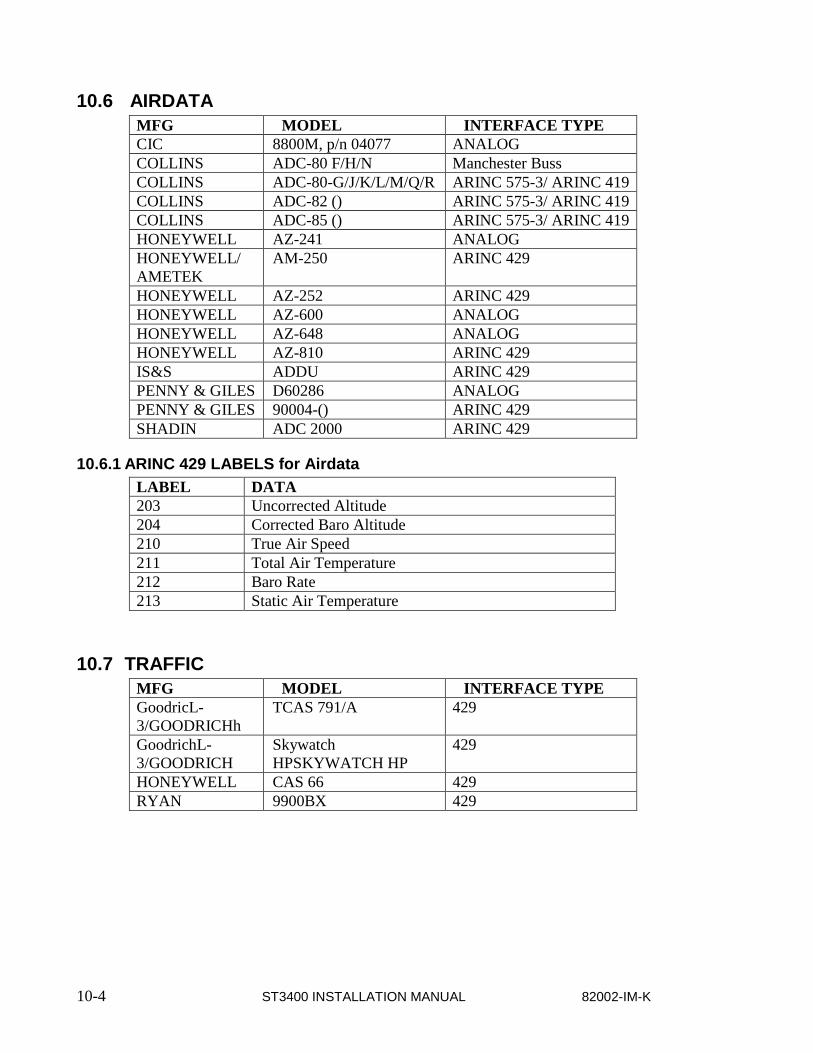
10-4 ST3400 INSTALLATION MANUAL 82002-IM-K
10.6 AIRDATA MFG MODEL INTERFACE TYPE CIC 8800M, p/n 04077 ANALOG COLLINS ADC-80 F/H/N Manchester Buss COLLINS ADC-80-G/J/K/L/M/Q/R ARINC 575-3/ ARINC 419 COLLINS ADC-82 () ARINC 575-3/ ARINC 419 COLLINS ADC-85 () ARINC 575-3/ ARINC 419 HONEYWELL AZ-241 ANALOG HONEYWELL/ AMETEK
AM-250 ARINC 429
HONEYWELL AZ-252 ARINC 429 HONEYWELL AZ-600 ANALOG HONEYWELL AZ-648 ANALOG HONEYWELL AZ-810 ARINC 429 IS&S ADDU ARINC 429 PENNY & GILES D60286 ANALOG PENNY & GILES 90004-() ARINC 429 SHADIN ADC 2000 ARINC 429
10.6.1 ARINC 429 LABELS for Airdata LABEL DATA 203 Uncorrected Altitude 204 Corrected Baro Altitude 210 True Air Speed 211 Total Air Temperature 212 Baro Rate 213 Static Air Temperature
10.7 TRAFFIC MFG MODEL INTERFACE TYPE GoodricL-3/GOODRICHh
TCAS 791/A 429
GoodrichL-3/GOODRICH
Skywatch HPSKYWATCH HP
429
HONEYWELL CAS 66 429 RYAN 9900BX 429

82002-IM-K ST3400 INSTALLATION MANUAL 11-1
11 APPENDIX B: ENVIRONMENTAL QUALIFICATION FORM RTCA/D0-160D Environmental Qualification Form
NAMEPLATE NOMENCLATURE: [(A2)(F1)]ZBAB[(H)(R)]XXXXXXZBABB[WW]M[XXF2]XXA TYPE/MODEL NO: ST3400 TSO NUMBERS: C151a, C92c, C113
MANUFACTURER’S SPECIFICATION AND/OR OTHER APPLICABLE SPECIFICATION: a.) Design Requirements & Objectives For ST3400 TAWS, document number 82002-0010
b.) RTCA D0-160D Environmental Plan For Sandel ST3400 TAWS Class A/B, document number 82002-0090 MANUFACTURER: Sandel Avionics, Inc. ADDRESS: 2401 Dogwood Way Vista, CA 92083 REVISION & CHANGE NOS. OF D0-160: Revision D, Change Nos. 1 & 2
DATE TESTED: From: 1/31/02 To: 3/20/02
ENVIRONMENTAL
TESTS RTCA/DO-
160D SECTION
Equipment Test
Category
Notes
Temperature & Altitude Temperature Variation (combined): Low Temperature -Ground Survival -Operational High Temperature -Ground Survival -Operational Altitude -Decompression -Overpressure
4.0 5.0 4.5.1
4.5.2 & 4.5.3
4.6 4.6.2 4.6.3
[(A2)(F1)B] PASS
In-Flight Loss of Cooling 4.5.4 [(A2)Z] PASS Humidity 6.0 A PASS Operational Shock and Crash Safety 7.0 B PASS Vibration 8.0 [(H)(R)] PASS:
RESONANT FREQUENCIES: Section 8.7.2, Step a. and d.:
Pre-Scan: X: 195Hz, Y: 500Hz, Z: 160Hz Post-Scan: X: 195Hz, Y: 450Hz, Z: 150Hz
Section 8.8.1.3, Steps a. and e.: Pre-Scan: X: 190Hz, Y: 425Hz, Z: 145Hz Post-Scan: X: 190Hz, Y: 625Hz, Z: 145Hz
Section 8.8.1.3, Steps b. and d.: Pre-Scan: X: 190Hz, Y: 390Hz, Z: 150Hz Post-Scan: X: 190Hz, Y: 625Hz, Z: 150Hz
Explosion 9.0 X
Water-proofness 10.0 X
Fluids Susceptibility 11.0 X
Sand and Dust 12.0 X
Fungus 13.0 X
Salt Spray 14.0 X
Magnetic Effect 15.0 Z PASS Power Input 16.0 B PASS Voltage Spike 17.0 A PASS Audio Frequency Susceptibility 18.0 B PASS Induced Signal Susceptibility 19.0 B PASS Radio Frequency Susceptibility 20.0 [WW] PASS Radio Frequency Emission 21.0 M PASS Lightning Induced Transient Susceptibility 22.0 [XX(EF)2] PASS Lightning Direct Effects 23.0 X
Icing 24.0 X
Electrostatic Discharge 25.0 A PASS

11-2 ST3400 INSTALLATION MANUAL 82002-IM-K
THIS PAGE INTENTIONALLY LEFT BLANK

82002-IM-K ST3400 INSTALLATION MANUAL 12-1
12 APPENDIX C: STC
12.1 STC Permission Please contact Sandel Avionics, Inc. for permission to use these STC’s.

12-2 ST3400 INSTALLATION MANUAL 82002-IM-K
12.2 STC: Cessna 421C Series

82002-IM-K ST3400 INSTALLATION MANUAL 12-3
12.3 STC: King Air C90, 200, 300 and B300 Series
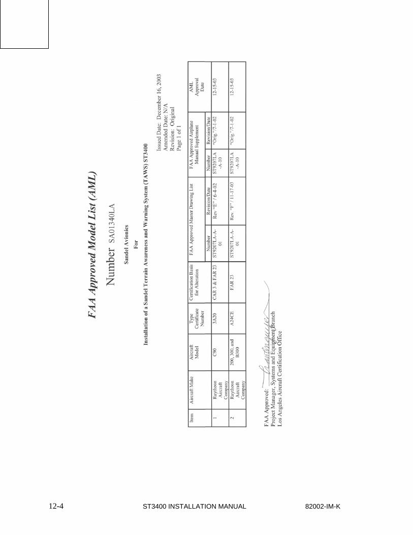
12-4 ST3400 INSTALLATION MANUAL 82002-IM-K
[(A2)(F1)]ZB
NAMEPLATE
TYPE/MOD
ST3400
TSO NUMB
C151a, C9
MANUFACT
a.) Design Requirements
cument number 82002
- 0010 b.) RTCA D0 - 160D Environmental Plan For
- 0090 MANUFACT
Sandel
ADDRESS:
2401 Dogw
Vista, CA 920
REVISION &
- 160: Revision
Change
Nos. 1 & 2
DATE TESTED
From: 1/31/02
To: 3/20/02
ENVIRONMENTAL
TESTS RTCA/DO - 160D SECTION Equipment Test Category Notes Temperature & Altitude
Temperature Variation (co
Low Temperature - Ground Survival - Operational High Temperatur e - Ground Survival - Operational Altitude - Decompression - Overpressure 4.0 5.0 4.5.1 4.5.2 & 4.5.3 4.6 4.6.2 4.6.3 [(A2)(F1)B] PASS In - Flight Loss of Cooling
4.5.4 [(A2)Z] PASS: U pgrade to Category Y is recomme
Humidity 6.0 A PASS Operationa
l Shock and Crash
7.0 B PASS Vibration 8.0 [H R] PASS: RESONANT FREQUENCIES:
Section 8.7.2, Step a. and d.:
Pre - Scan: X: 195Hz, Y: 500Hz, Z: 160Hz
Post - Scan: X: 195Hz, Y: 450Hz, Z: 150Hz
Section 8.8.1.3, Steps a. and
Pre - Scan: X: 190H z, Y: 425Hz, Z: 145Hz
Post - Scan: X: 190Hz, Y: 625Hz, Z: 145Hz
Section 8.8.1.3, Steps b. and
Pre - Scan: X: 190Hz, Y: 390Hz, Z: 150Hz
Post - Scan: X: 190Hz, Y: 625Hz, Z: 150Hz
Explosion 9.0 X Water - proofness 10.0 X Fluids Susceptibility 1 1.0 X Sand and Dust 12.0 X Fungus 13.0 X Salt Spray 14.0 X Magnetic Effect
15.0 Z PASS Power Input 16.0 B PASS Voltage Spike 17.0 A PASS Audio Frequency Susc
18.0 B PASS Induced Signal Susceptib
19.0 B PASS Radio Frequency Susc
ptibility 20.0 [WW] PASS Radio Frequency Emiss
21.0 M PASS Lightning Induced Transient
Susceptibility 22.0 [XX(EF)2] PASS Lightning Direct Effects 23.0

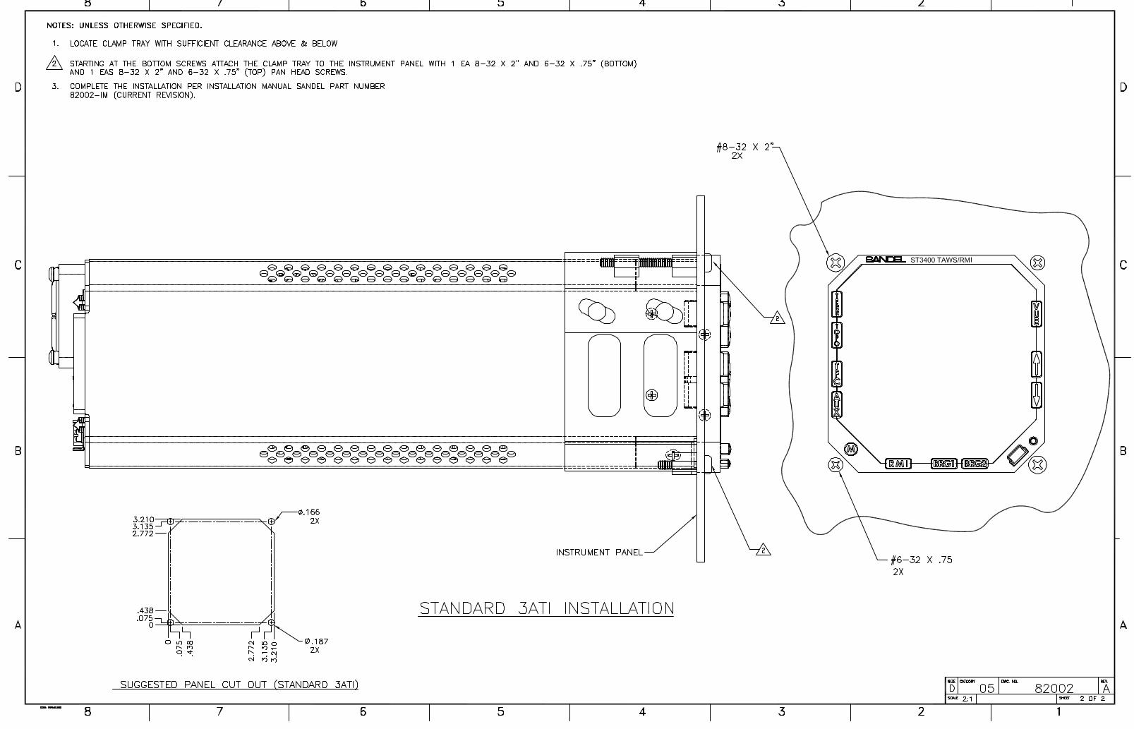

NOTES: UNLESS OTHERWISE SPECIFIED
.553.165
.35
9.26
.16
TOP VIEW
3.165
RIGHT SIDE VIEWLEFT SIDE VIEW
CG1.650
5.650
3.285
3.285
FRONT VIEW
BACK VIEW
BOTTOM VIEW
D
C
B
A
A
B
C
D
CAD GENERATED DRAWING,
DO NOT MANUALLY UPDATE
SCALE: 1:2
SIZE
CAD FILE:
CATEGORY
B
SHEET 1 OF 1
REV.
LAYOUT, ST3400
DATEAPPROVALS
DRAWN
CHECKED
RESP ENG
MFG ENG
APPROVAL
UNLESS OTHERWISE SPECIFIED
DIMENSIONS ARE IN INCHES
TOLERANCES ARE:
FRACTIONS DECIMALS ANGLES
X/X .XX .01 .5
MATERIAL
FINISH
--
--
DO NOT SCALE DRAWINGAPPLICATION
USED ONNEXT ASSY
ITEM
NO.PART OR
IDENTIFYING NO.NOMENCLATUREOR DESCRIPTION
MATERIAL SPECIFICATION
QTYREQD
PARTS LIST
12345678
8 7 6 5 4 3 2 1REVISIONS
REV. DESCRIPTION DATE APPROVED
VISTA, CA
A
.XXX .005
82002
P.TAYLOR 01/24/02
ST3400
A INITIAL RELEASE
COMPUTER GENERATED DRAWINGDO NOT REVISE MANUALLY
DWG. NO.
07

A
A
B
B
C
C
D
D
E
E
4 4
3 3
2 2
1 1
Title
Size Document Number Rev
Create: Sheet of
Category
Mod:Wednesday, August 15, 2001
82002-10 HSYSTEM BLOCK DIAGRAM
SANDEL Vista, Ca.
B
1
ST3400 INSTALLATION DRAWING
Wednesday, January 15, 2014
Title
Size Document Number Rev
Create: Sheet of
Category
Mod:Wednesday, August 15, 2001
82002-10 HSYSTEM BLOCK DIAGRAM
SANDEL Vista, Ca.
B
1
ST3400 INSTALLATION DRAWING
Wednesday, January 15, 2014
Title
Size Document Number Rev
Create: Sheet of
Category
Mod:Wednesday, August 15, 2001
82002-10 HSYSTEM BLOCK DIAGRAM
SANDEL Vista, Ca.
B
1
ST3400 INSTALLATION DRAWING
Wednesday, January 15, 2014
TERRAINAWARENESS and WARNING SYSTEMRADALT
GPS/FMSSANDELST3400
INVERTER
AUTOPILOT
SWITCHANNUNCIATORS(optional)
ARINC 429
WARNING DISCRETE
CAUTION DISCRETE
26VAC 400 HZ (opt)
TAWS INHIBIT SWITCH
429 OR ANALOG
AIRFRAMEGEAR DOWN DISCRETE
FLAP DOWN DISCRETE
#2 ST3400(optional)
INTERLINK
ENGAGED DISCRETE
POWER &GROUND
28VDC
POWER GROUND
TAWS INHIBIT DISCRETE
REQUIRED FORHDG, ADF AND AIR DATA XYZREFERENCE INPUT
COMMENTSA
REV04/11/02
DATEA/R 484 INITIAL RELEASE
B05/21/02 A/R 525 ADDED OAT TO AIRDATA
CONFIGURATION MODULE
ORNAV & LOCVOR/LOC COMPOSITE & GLIDESLOPE
ARINC 429
HEADING429 OR XYZ
AIR DATACORR. BARO ALT,TAS, VS, OAT
429 OR ANALOG
AUDIO600 ohm
ADF
429 OR SIN-COSOR XYZ
(OPTIONAL)
Serial
COMPUTER CONTROLLED DRAWINGDO NOT REVISE MANUALLY
(OPTIONAL)
G08/04/03 A/R 638 Configuration Module Optional
TRAFFIC ARINC 429
H02/18/04 A/R 675 Added Traffic Interface.
(OPTIONAL)
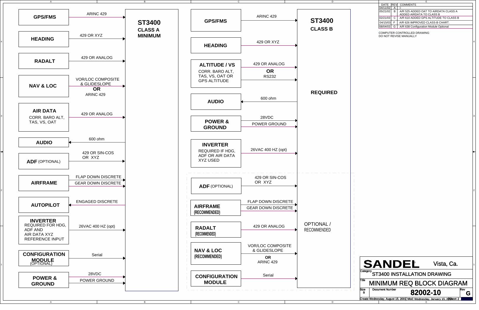
A
A
B
B
C
C
D
D
E
E
4 4
3 3
2 2
1 1
Title
Size Document Number Rev
Create: Sheet of
Category
Mod:Wednesday, August 15, 2001
82002-10 GMINIMUM REQ BLOCK DIAGRAM
SANDEL Vista, Ca.
B
2
ST3400 INSTALLATION DRAWING
Wednesday, January 15, 2014
Title
Size Document Number Rev
Create: Sheet of
Category
Mod:Wednesday, August 15, 2001
82002-10 GMINIMUM REQ BLOCK DIAGRAM
SANDEL Vista, Ca.
B
2
ST3400 INSTALLATION DRAWING
Wednesday, January 15, 2014
Title
Size Document Number Rev
Create: Sheet of
Category
Mod:Wednesday, August 15, 2001
82002-10 GMINIMUM REQ BLOCK DIAGRAM
SANDEL Vista, Ca.
B
2
ST3400 INSTALLATION DRAWING
Wednesday, January 15, 2014
GPS/FMS ST3400
AUDIO
ARINC 429
429 OR XYZ
26VAC 400 HZ (opt)
600 ohm
CLASS B
GPS/FMSST3400
AUTOPILOT
ARINC 429
AIRFRAME GEAR DOWN DISCRETEFLAP DOWN DISCRETE
CLASS A MINIMUM
INVERTERREQUIRED IF HDG,ADF OR AIR DATAXYZ USED
RADALT
NAV & LOC
AIR DATA
INVERTER
AUDIO
ADF
26VAC 400 HZ (opt)
429 OR ANALOG
ARINC 429
600 ohm
429 OR SIN-COSOR XYZ
(OPTIONAL)
CORR. BARO ALT,TAS, VS, OAT
429 OR ANALOG
OR
REQUIRED FOR HDG,ADF AND AIR DATA XYZREFERENCE INPUT
VOR/LOC COMPOSITE & GLIDESLOPE
HEADING429 OR XYZ
ENGAGED DISCRETE
ALTITUDE / VSCORR. BARO ALT,TAS, VS, OAT ORGPS ALTITUDE
429 OR ANALOG
HEADING
CONFIGURATION MODULE
POWER &GROUND
28VDCPOWER GROUND
Serial
RS232OR
POWER GROUND28VDC
POWER &GROUND
ARINC 429
Serial
AIRFRAME(RECOMMENDED)
RADALT(RECOMMENDED)
NAV & LOC(RECOMMENDED)
CONFIGURATION MODULE
VOR/LOC COMPOSITE & GLIDESLOPE
429 OR ANALOG
OR
FLAP DOWN DISCRETEGEAR DOWN DISCRETE
OPTIONAL /RECOMMENDED
REQUIRED
ADF
429 OR SIN-COSOR XYZ
(OPTIONAL)
COMMENTSA
REV04/11/02
DATEA/R 484 INITIAL RELEASE
B05/21/02 A/R 525 ADDED OAT TO AIRDATA CLASS AADDED AIRDATA TO CLASS B
COMPUTER CONTROLLED DRAWINGDO NOT REVISE MANUALLY
C02/21/03 A/R 610 ADDED GPS ALTITUDE TO CLASS B
04/15/03 F A/R 626 IMPROVED CLASS-B CHART.
(OPTIONAL)
G08/04/03 A/R 638 Configuration Module Optional

A
A
B
B
C
C
D
D
E
E
4 4
3 3
2 2
1 1
Title
Size Document Number Rev
Create: Sheet of
Category
Mod:Monday, July 02, 200182002-10 J
POWER & AUDIO
SANDEL Vista, Ca.
B
3
ST3400 INSTALLATION DRAWING
Tuesday, February 04, 2014
Title
Size Document Number Rev
Create: Sheet of
Category
Mod:Monday, July 02, 200182002-10 J
POWER & AUDIO
SANDEL Vista, Ca.
B
3
ST3400 INSTALLATION DRAWING
Tuesday, February 04, 2014
Title
Size Document Number Rev
Create: Sheet of
Category
Mod:Monday, July 02, 200182002-10 J
POWER & AUDIO
SANDEL Vista, Ca.
B
3
ST3400 INSTALLATION DRAWING
Tuesday, February 04, 2014
PWR A
GND IN
J3
PWR A
GND IN
91
311
J2
16
TAWS POWER
5A
J1
#1 26VAC INVERTER IN 16 26 VAC 400HZ #1 (OPT)
ST3400
J2 S
ECO
NDAR
Y
UNSWITCHED AUDIO IN
J1 PRIM
ARY
30
#20 AWG#20 AWG
#20 AWG#20 AWG
26 VAC 400HZ #2 (OPT)
AC REFERENCE FOR INPUTS ON J1
#2 26VAC INVERTER IN
NOTES:1. AC REFERENCE REQUIRED FOR ARINC 407 XYZ INPUTS ARE USED ON J1 & J2. (HDG, ADF & AIRDATA XYZ)
#2 INVERTER INPUT CAN BE JUMPERED FROM#1 INVERTER INPUT OR A SEPERATE #2 INVERTER INPUT IF REQUIRED. ARINC 407 XYZ INPUTS ON J2MUST HAVE THE SAMEAC REFERENCE AS #2 INVERTER INPUT P2-16.
04/11/02 A A/R 484 INITIAL RELEASEDATE REV COMMENTS
COMPUTER CONTROLLED DRAWINGDO NOT REVISE MANUALLY
SHIELD GROUND 1
SHIELD GROUND 1AC REFERENCE FOR INPUTS ON J2
SEE NOTE 1
2.
IF AIRCRAFT HAS ONLY ONE UNSWITCHED INPUTAND MULTIPLE SOURCES, ADD A 470-680 OHMRESISTOR IN SERIES WITH EACH SOURCE FORISOLATION OR USE RELAY
3.
04/12/03 F A/R 626 ADDED NOTE 3
SEE NOTE 3
Primary Power
Inverter
Audio Output
ST3400
ST3400
04/07/04 H2A/R 717 Speaker output available for MOD-A
TAWS PWR THIS IS AN ACCEPTABLE ALTERNATIVE MEANS OFENABLING TAWS AUDIO WHEN REQUIRED BYSYSTEM CONSIDERATIONSP3-8 (TCAS INH)
TCAS AUDIO
15
LOW LEVEL AUDIO OUT
SPEAKER OUT
AUDIO PANEL
Speaker output available with MOD-A only. Driveseparate cockpit speaker if existing audio amplifiernot available. If there is a TCAS installed ensureprioritization is accomplished with a relay.
4.
SEE NOTE 4
07/1/04 JA/R 697 ADDED AUDIO ENABLE RELAY
01/23/14 K A/R 1356 Audio relay orientation corrected

A
A
B
B
C
C
D
D
E
E
4 4
3 3
2 2
1 1
Title
Size Document Number Rev
Create: Sheet of
Category
Mod:Monday, July 02, 200182002-10 J
GPS/FMS ARINC 429
SANDEL Vista, Ca.
B
4
ST3400 INSTALLATION DRAWING
Wednesday, January 15, 2014
Title
Size Document Number Rev
Create: Sheet of
Category
Mod:Monday, July 02, 200182002-10 J
GPS/FMS ARINC 429
SANDEL Vista, Ca.
B
4
ST3400 INSTALLATION DRAWING
Wednesday, January 15, 2014
Title
Size Document Number Rev
Create: Sheet of
Category
Mod:Monday, July 02, 200182002-10 J
GPS/FMS ARINC 429
SANDEL Vista, Ca.
B
4
ST3400 INSTALLATION DRAWING
Wednesday, January 15, 2014
COMMENTSA
REV04/11/02
DATEA/R 484 INITIAL RELEASE
B09/25/02 A/R 564 added Garmin GPS165
ST3400 J1 PRIM
ARY
#1 FMS 429 BIN 17 47 I8 39
GAR
MIN
GNS
-4XX
P400
1
KING
KLN
-900
P900
1
SHIELD GROUND 1
ARINC 429 TX A
ARINC 429 TX B
SOFTWARESELECT SELECT EQUIPMENT MODEL
#1 FMS 429 AIN 31 46 I7 20
15
GAR
MIN
GPS
165
J101
16
ST3400
J2 S
ECO
NDAR
Y
17#2 FMS 429 BIN
SHIELD GROUND 1
31#2 FMS 429 AIN
SECONDARY INPUTS OPTIONAL
C02/21/03 A/R 610 Depict J1 & J2 Seperately
COMPUTER CONTROLLED DRAWINGDO NOT REVISE MANUALLY
PORTSELECT
40
II M
ORR
OW
200
1P1
41
II M
ORR
OW
210
1P1
43
4447
GAR
MIN
GNS
-5XX
P500
1
46
Added II Morrow 2001, 2101 & UNS-1X
Trim
ble
2101
I/O
J2 (LO
W O
R HI
GH
SPEE
D)
G08/04/03 A/R 638 added Trimble 2101 I/O
UNIV
ERSA
LUN
S-1X
(LO
W o
r HIG
H SP
EED)
PORTSELECT
23
KING
KLN
-90B
P901
24
G110/17/03 A/R 661 added King KLN 900
47 I8 39
GAR
MIN
GNS
-4XX
P400
1
KING
KLN
-900
P900
1
ARINC 429 TX A
ARINC 429 TX B
SOFTWARESELECT SELECT EQUIPMENT MODEL
46 I7 20
15
GAR
MIN
GPS
165
J101
16
PORTSELECT
40
II M
ORR
OW
200
1P1
41
II M
ORR
OW
210
1P1
43
4447
GAR
MIN
GNS
-5XX
P500
1
46
Trim
ble
2101
I/O
J2 (LO
W O
R HI
GH
SPEE
D)
UNIV
ERSA
LUN
S-1X
(LO
W o
r HIG
H SP
EED)
GNS
Xls
(Low
or H
igh
Spee
d)
PORTSELECT
23
KING
KLN
-90B
P901
24
GPS/FMS 1
GPS/FMS 2
J08/05/04 A/R 717 GPS/FMS ARINC PIN 17 WAS GNS GNS-X
GNS
Xls
(Low
or H
igh
Spee
d)

A
A
B
B
C
C
D
D
E
E
4 4
3 3
2 2
1 1
Title
Size Document Number Rev
Create: Sheet of
Category
Mod:Monday, July 02, 200182002-10 H
RS232 GPS INTERFACE
SANDEL Vista, Ca.
B
5
ST3400 INSTALLATION DRAWING
Friday, January 24, 2014
Title
Size Document Number Rev
Create: Sheet of
Category
Mod:Monday, July 02, 200182002-10 H
RS232 GPS INTERFACE
SANDEL Vista, Ca.
B
5
ST3400 INSTALLATION DRAWING
Friday, January 24, 2014
Title
Size Document Number Rev
Create: Sheet of
Category
Mod:Monday, July 02, 200182002-10 H
RS232 GPS INTERFACE
SANDEL Vista, Ca.
B
5
ST3400 INSTALLATION DRAWING
Friday, January 24, 2014
COMMENTSE
REV02/21/03
DATEA/R 610 INITIAL RELEASE
COMPUTER CONTROLLED DRAWINGDO NOT REVISE MANUALLY
ST3400
17
#1 FMS RS232 IN LO 31
F04/14/03 A/R 626 Added KLN94 GPS
If GPS uses two RS232 ports, contact Sandel beforeinterfacing an RS232 OAT source. See OAT page.
ST3400J1
#1 FMS RS232/422 IN HI
17
SHIELD GROUND 1
#1 FMS RS232/422 IN LO
31
G110/17/03 A/R 661 added Trimble 2000/3000/2101 andUPS GX Series
H02/18/04 A/R 675 Added FreeFlight 1201 GPS#2 Shown. Pin 26 shown grounded
GPS/FMS 1
ST3400J1
#1 FMS RS232/422 IN HI 17
SHIELD GROUND 1
#1 FMS RS232/422 IN LO 31
2.Horizontal Guidance only used.1.
NOTES:
3. 1201 GPS provides horizontal and vertical position. No flight plan data available.
SHIELD GROUND 1
#1 FMS RS232 IN HI
ST3400
17
#2 FMS RS232 IN LO 31
Trimble2000/3000 J1
ST3400J2
#2 FMS RS232/422 IN HI
17
SHIELD GROUND 1
#2 FMS RS232/422 IN LO
31 3
RS422 OUT TXD1/2+ 15
SOFTWARESELECT
TRIMBLE2000/3000
Trimble 2101 J1
5
37
TRIMBLE 2101
OR
OR
23
9RS422 OUT TXD1/2-
GPS/FMS 2
GX50/60SHIELD GROUND 1
J2ST3400
SOFTWARESELECT
5
UPSGX50/6037 PIN
1201
RS232 OUT TXD1
GROUND
7
2 2331#2 FMS RS232/422 IN LO
#2 FMS RS232/422 IN HI 17
1SHIELD GROUND
#2 FMS RS232 IN HI
SOFTWARESELECT
GROUND
KLN94
Trimble2000/3000 J1
TRIMBLE 2101
15
5
1201
SOFTWARESELECT
37
RS422 OUT TXD1/2-
GENERALRS232OUTPUT
RS422 OUT TXD1/2+
2
RS232 OUT TXD1 7
5 93
23
10
Trimble 2101 J1
FREEFLIGHT1201 WAAS (25 PIN)
OR
BENDIX/KING KLN94 P941
TRIMBLE2000/3000
GX50/60
OR
UPSGX50/6037 PIN
2
SOFTWARESELECT
J1 J2
FREEFLIGHT1201 WAAS (25 PIN)
(SEENOTES1/3)
2
BENDIX/KING KLN94 P941
KLN94SOFTWARESELECT
GENERALRS232OUTPUT
(SEENOTES1/3)
01/23/14 JA/R 1356 Corrected pin descriptions forJ1-17, J1-31, J2-17, and J2-31 for Trimble2000/3000/2101 interface. ChangedFreeflight ground pin from 23 to 10. Deleted#1 and #2 RS232 GPS ALT IN and FMSRS232 IN LO. Added ground to KLN94RS232 output. Deleted note regarding KLN94software revision level.

A
A
B
B
C
C
D
D
E
E
4 4
3 3
2 2
1 1
Title
Size Document Number Rev
Create: Sheet of
Category
Mod:Monday, July 02, 200182002-10 H
GARMIN GNS4XX/5XX
SANDEL Vista, Ca.
B
6
ST3400 INSTALLATION DRAWING
Thursday, January 23, 2014
Title
Size Document Number Rev
Create: Sheet of
Category
Mod:Monday, July 02, 200182002-10 H
GARMIN GNS4XX/5XX
SANDEL Vista, Ca.
B
6
ST3400 INSTALLATION DRAWING
Thursday, January 23, 2014
Title
Size Document Number Rev
Create: Sheet of
Category
Mod:Monday, July 02, 200182002-10 H
GARMIN GNS4XX/5XX
SANDEL Vista, Ca.
B
6
ST3400 INSTALLATION DRAWING
Thursday, January 23, 2014
COMMENTSE
REV02/21/03
DATEA/R 610 INITIAL RELEASE
SECONDARY INPUTS OPTIONAL
ST3400 J1
PRIM
ARY
#1 FMS 429 B IN 1747
ARINC 429 TX AARINC 429 TX B
#1 FMS 429 A IN 31 46
47
46
GARMINGNS-400/420P4001
GARMINGNS-500P5001
#1 NAV 429 B IN
#1 NAV 429 A IN 35
21NAV 429 B TX
NAV 429 A TX
SHIELD GROUND 1
11#1 FMS RS232 IN HI 2. ST3400 MAINTENANCE PAGE ITEMS: LNAV-1: GNS4XX/5XX (429_232) LNAV-2: GNS4XX/5XX (429_232) NAV-1: 429 (430/530) NAV-2: 429 (430/530) GS-1: 429 (430/530) GS-2: 429 (430/530)
3. GARMIN SETUP ITEMS MAIN ARINC-429 CONFIGURATION RECEIVER 1: OUT: LOW, GAMA 429 Graphics w/Int SDI: LNAV 1 (SDI1) VOR/LOC/GS ARINC-429 CONFIGURATION: SPD RX: LOW SPD TX: LOW SDI: VOR/ILS 1 (SDI1) MAIN RS232 CONFIG INPUT OUTPUT CHAN 1-4 OFF HW-EPGWS
MAIN ARINC-429 CONFIGURATION RECEIVER 2: OUT: LOW, GAMA 429 Graphics w/Int SDI: LNAV 2 (SDI2) VOR/LOC/GS ARINC-429 CONFIGURATION: SPD RX: LOW SPD TX: LOW SDI: VOR/ILS 2 (SDI2) MAIN RS232 CONFIG INPUT OUTPUT CHAN 1-4 OFF HW-EPGWS
RS232 TX
GARMINGNS-430P4001
24
47
23
47
GARMINGNS-530P5001
46
24
46
Select 1 of the RS232 TX OutputsA Channel needs to be dedicated to the ST3400
23
COMPUTER CONTROLLED DRAWINGDO NOT REVISE MANUALLY
NOTES:
1. GARMIN 400/500 SERIES UNITS MUST HAVE MAIN & GPS SOFTWARE 3.0 OR ABOVE. GARMIN 400/500 SERIES UNITS MUST HAVE PRESSURE ALTITUDE INTERFACED TO RECEIVER
G110/17/03 A/R 661 Added 430/530 Connectors Designators
P5006P4006
GPS/FMS 1
H01/20/14 A/R 1356 Grounds added
#1 FMS RS232 IN LO 26 RS232 GND
GARMINGNS-430P4001
24
47
23
47
GARMINGNS-530P5001
46
24
46
Select 1 of the RS232 TX OutputsA Channel needs to be dedicated to the ST3400
23
GPS/FMS 2
#2 FMS RS232 IN LO 26
P5006P4006
RS232 GND
ST3400
J2
PRIM
ARY
#2 FMS 429 B IN 1747
ARINC 429 TX AARINC 429 TX B
#2 FMS 429 A IN 31 46
47
46
GARMINGNS-400/420P4001
GARMINGNS-500P5001
#2 NAV 429 B IN
#2 NAV 429 A IN 35
21NAV 429 B TX
NAV 429 A TX
SHIELD GROUND 1
11#2 FMS RS232 IN HI RS232 TX
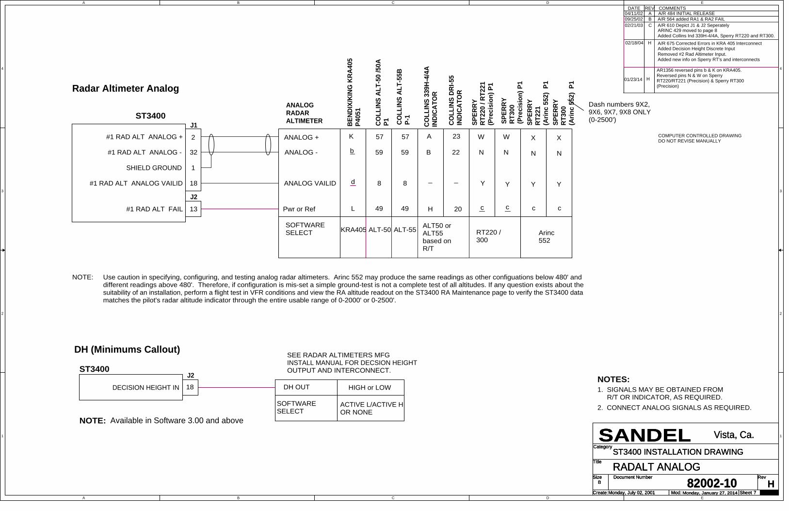
A
A
B
B
C
C
D
D
E
E
4 4
3 3
2 2
1 1
Title
Size Document Number Rev
Create: Sheet of
Category
Mod:Monday, July 02, 200182002-10 H
RADALT ANALOG
SANDEL Vista, Ca.
B
7
ST3400 INSTALLATION DRAWING
Monday, January 27, 2014
Title
Size Document Number Rev
Create: Sheet of
Category
Mod:Monday, July 02, 200182002-10 H
RADALT ANALOG
SANDEL Vista, Ca.
B
7
ST3400 INSTALLATION DRAWING
Monday, January 27, 2014
Title
Size Document Number Rev
Create: Sheet of
Category
Mod:Monday, July 02, 200182002-10 H
RADALT ANALOG
SANDEL Vista, Ca.
B
7
ST3400 INSTALLATION DRAWING
Monday, January 27, 2014
COMMENTSA
REV04/11/02
DATEA/R 484 INITIAL RELEASE
B09/25/02 A/R 564 added RA1 & RA2 FAIL02/21/03 C A/R 610 Depict J1 & J2 Seperately
ARINC 429 moved to page 8 Added Collins Ind 339H-4/4A, Sperry RT220 and RT300.
NOTES:1. SIGNALS MAY BE OBTAINED FROM R/T OR INDICATOR, AS REQUIRED.2. CONNECT ANALOG SIGNALS AS REQUIRED.
SHIELD GROUND
cc
Y
57
20
#1 RAD ALT ANALOG -
K
d Y
W
SPER
RYRT
300
(Pre
cisi
on) P
1
KRA405
BEND
IX/K
ING
KRA
405
P405
1
b 59 N
L
SPER
RY
RT22
0 / R
T221
(Pre
cisi
on) P
1
W
H
COLL
INS
DRI-5
5IN
DICA
TOR
_
#1 RAD ALT ANALOG +
22
23
J2
4913#1 RAD ALT FAIL Pwr or Ref 49
ALT50 orALT55based onR/T
ALT-55ALT-50
ST3400
N
SOFTWARESELECT
8
COLL
INS
ALT-
55B
P-1
57
59
18#1 RAD ALT ANALOG VAILID
ANALOGRADARALTIMETER
ANALOG -
ANALOG VAILID
ANALOG +
COLL
INS
ALT-
50 /5
0AP1
2
32
1
J1 COLL
INS
339H
-4/4
AIN
DICA
TOR
_
B
A
8
02/18/04 H A/R 675 Corrected Errors in KRA 405 InterconnectAdded Decision Height Discrete InputRemoved #2 Rad Altimeter Input. Added new info on Sperry RT's and interconnects
COMPUTER CONTROLLED DRAWINGDO NOT REVISE MANUALLY
SEE RADAR ALTIMETERS MFG INSTALL MANUAL FOR DECSION HEIGHT OUTPUT AND INTERCONNECT.ST3400
HIGH or LOWDECISION HEIGHT IN 18
J2
ACTIVE L/ACTIVE HOR NONE
SOFTWARESELECT
DH OUT
NOTE: Available in Software 3.00 and above
DH (Minimums Callout)
Radar Altimeter Analog
NOTE: Use caution in specifying, configuring, and testing analog radar altimeters. Arinc 552 may produce the same readings as other configuations below 480' anddifferent readings above 480'. Therefore, if configuration is mis-set a simple ground-test is not a complete test of all altitudes. If any question exists about thesuitability of an installation, perform a flight test in VFR conditions and view the RA altitude readout on the ST3400 RA Maintenance page to verify the ST3400 datamatches the pilot's radar altitude indicator through the entire usable range of 0-2000' or 0-2500'.
RT220 / 300
SPER
RYRT
221
(Arin
c 55
2) P
1
N
X
Y
c
Dash numbers 9X2,9X6, 9X7, 9X8 ONLY(0-2500')
Arinc552
SPER
RYRT
300
(Arin
c 55
2) P
1
N
X
Y
c
01/23/14 H
AR1356 reversed pins b & K on KRA405.Reversed pins N & W on SperryRT220/RT221 (Precision) & Sperry RT300(Precision)

A
A
B
B
C
C
D
D
E
E
4 4
3 3
2 2
1 1
Title
Size Document Number Rev
Create: Sheet of
Category
Mod:Monday, July 02, 200182002-10 H
RADALT ARINC 429
SANDEL Vista, Ca.
B
8
ST3400 INSTALLATION DRAWING
Wednesday, January 15, 2014
Title
Size Document Number Rev
Create: Sheet of
Category
Mod:Monday, July 02, 200182002-10 H
RADALT ARINC 429
SANDEL Vista, Ca.
B
8
ST3400 INSTALLATION DRAWING
Wednesday, January 15, 2014
Title
Size Document Number Rev
Create: Sheet of
Category
Mod:Monday, July 02, 200182002-10 H
RADALT ARINC 429
SANDEL Vista, Ca.
B
8
ST3400 INSTALLATION DRAWING
Wednesday, January 15, 2014
COMMENTSREVDATEE02/21/03 A/R 610 Radar Altimeter ARINC 429 interface moved from orignal sheet 5, added Bendix/King KRA405B
COMPUTER CONTROLLED DRAWINGDO NOT REVISE MANUALLY
#1 RAD ALT 429 A RX
#1 RAD ALT 429 B RX
SHIELD GROUND
ST3400
3
2
COLL
INS
RAC-
870
P-1
J1 P
RIM
ARY
1
32
2 ARINC 429 TX A
ARINC 429 TX B
ARINC 429RADARALTIMETER
SOFTWARESELECT ARINC 429
C
B
BEND
IX/K
ING
KRA
405
BP4
051
NOTES:1. SIGNALS MAY BE OBTAINED FROM R/T OR INDICATOR, AS REQUIRED.2. CONNECT DIGITAL SIGNALS AS REQUIRED.
02/18/04 H A/R 675 Removed #2 Radar Altimeter
SEE RADAR ALTIMETERS MFG INSTALL MANUAL FOR DECSION HEIGHT OUTPUT AND INTERCONNECT.ST3400
HIGH or LOWDECISION HEIGHT IN 18
J2
ACTIVE L/ACTIVE HOR NONE
SOFTWARESELECT
DH OUT
NOTE: Available in Software 3.00 and above
DH (Minimums Callout)
Radar Altimeter 429

A
A
B
B
C
C
D
D
E
E
4 4
3 3
2 2
1 1
Title
Size Document Number Rev
Create: Sheet of
Category
Mod:Monday, July 02, 200182002-10 F
HDG ARINC 429
SANDEL Vista, Ca.
B
9
ST3400 INSTALLATION DRAWING
Wednesday, January 15, 2014
Title
Size Document Number Rev
Create: Sheet of
Category
Mod:Monday, July 02, 200182002-10 F
HDG ARINC 429
SANDEL Vista, Ca.
B
9
ST3400 INSTALLATION DRAWING
Wednesday, January 15, 2014
Title
Size Document Number Rev
Create: Sheet of
Category
Mod:Monday, July 02, 200182002-10 F
HDG ARINC 429
SANDEL Vista, Ca.
B
9
ST3400 INSTALLATION DRAWING
Wednesday, January 15, 2014
COMMENTSA
REV04/11/02
DATEA/R 484 INITIAL RELEASE
ST3400
ARINC 429 TX B
ARINC 429 TX A
J1 P
RIM
ARY
#1 HEADING 429 A IN
SHIELD GROUND
#1 HEADING 429 B IN
3
33
1
ARINCCOMPASSSYSTEM OUTPUT
ARINC 429SOFTWARESELECT
ST3400
J2 S
ECO
NDAR
Y
3
33 ARINC 429 TX B
ARINC 429 TX A
1
#2 HEADING 429 A IN
SHIELD GROUND
#2 HEADING 429 B IN
ARINCCOMPASSSYSTEMOUTPUT
ARINC 429SOFTWARESELECT
SECONDARY INPUTS OPTIONAL
02/21/03 B A/R 610 Depict J1 & J2 SeperatelyXYZ HDG moved to page 10
COMPUTER CONTROLLED DRAWINGDO NOT REVISE MANUALLY
#2 Heading not available when XYZ used forFlaps. See Airframe page.
NOTES:
F04/14/03 A/R 626 Added Note 1
1.
HDG 1 429
HDG 2 429

A
A
B
B
C
C
D
D
E
E
4 4
3 3
2 2
1 1
Title
Size Document Number Rev
Create: Sheet of
Category
Mod:Monday, July 02, 200182002-10 G
HDG XYZ
SANDEL Vista, Ca.
B
10
ST3400 INSTALLATION DRAWING
Wednesday, January 15, 2014
Title
Size Document Number Rev
Create: Sheet of
Category
Mod:Monday, July 02, 200182002-10 G
HDG XYZ
SANDEL Vista, Ca.
B
10
ST3400 INSTALLATION DRAWING
Wednesday, January 15, 2014
Title
Size Document Number Rev
Create: Sheet of
Category
Mod:Monday, July 02, 200182002-10 G
HDG XYZ
SANDEL Vista, Ca.
B
10
ST3400 INSTALLATION DRAWING
Wednesday, January 15, 2014
ST3400
HEADING Y
HEADING X
J1 P
RIM
ARY
#1 HEADING X
SHIELD GROUND HEADING Z
#1 HEADING Y
3
33
1
KI525ACOMPASSSYSTEMOUTPUT
#1 INVERTER EXCITATION IN EXCITATION HI16
P2
SOFTWARESELECT
COMMENTSREVDATE
ST3400 J2 S
ECO
NDAR
Y
3
33
1
#2 HEADING X
SHIELD GROUND
#2 HEADING Y
19
#2 INVERTER EXCITATION IN
#2 HEADING VALID
16
#2 Optional
E02/21/03
COMPUTER CONTROLLED DRAWINGDO NOT REVISE MANUALLY
W
Z
T
KSG 105
P
P1
XYZ OR XYZ-180
H
L
D
s
v
t
r
BENDIX/KINGKCS 55A
BENDIX/KINGKCS 305
OR
c
40
25
24
6
COLLINSMCS 65
P1DGS 65
EXCITATION LO u d f 5
SPERRY
HEADING Y
HEADING X
HEADING Z
HEADING VALID
EXCITATION HI
SOFTWARESELECT
EXCITATION LO
C-14AP1
HEADING VALID V V19 50P#1 HEADING VALID
REQUIRES AC REFERENCE INPUT
REQUIRES AC REFERENCE INPUT
HEADING VALID HI or LOW AS REQ'D
KI525AP2
W
Z
T
KSG 105
P
P1
XYZ OR XYZ-180
H
L
D
s
v
t
r
BENDIX/KINGKCS 55A
BENDIX/KINGKCS 305
OR
c
40
25
24
6
COLLINSMCS 65
P1DGS 65
u d f 5
V V 50P
HEADING VALID HI or LOW AS REQ'D
J
OR
e
Y
H
e
K
X
L
Z
M
a
b
SPERRY
C-14AP1
aL OR
H
J
e
Y
M
K Z
e
b
X
A/R 610 HDG XYZ interfacemoved from orignal sheet 6, added Bendix/KingKCS55A, Collins MCS65 and Sperry C14A
F04/14/03 A/R 626 Added Note 1
HDG 1 XYZ
2/14/04 G Removed note about flaps, now on P1
HDG 2 XYZCOMPASSSYSTEMOUTPUT

A
A
B
B
C
C
D
D
E
E
4 4
3 3
2 2
1 1
Title
Size Document Number Rev
Create: Sheet of
Category
Mod:Monday, July 02, 200182002-10 B
ADF ARINC 429
SANDEL Vista, Ca.
B
11
ST3400 INSTALLATION DRAWING
Wednesday, January 15, 2014
Title
Size Document Number Rev
Create: Sheet of
Category
Mod:Monday, July 02, 200182002-10 B
ADF ARINC 429
SANDEL Vista, Ca.
B
11
ST3400 INSTALLATION DRAWING
Wednesday, January 15, 2014
Title
Size Document Number Rev
Create: Sheet of
Category
Mod:Monday, July 02, 200182002-10 B
ADF ARINC 429
SANDEL Vista, Ca.
B
11
ST3400 INSTALLATION DRAWING
Wednesday, January 15, 2014
NOTES:1. OPTIONAL - USED FOR RMI OPERATION ONLY.
COMMENTSA
REV04/11/02
DATEA/R 484 INITIAL RELEASE
ST3400
J1 P
RIM
ARY
#1 ADF 429 AIN 4
#1 ADF 429 BIN 34
SHIELD GROUND 1
ADF 429 TX A
ADF 429 TX B
ADFARINC 429OUTPUT
SOFTWARESELECT
ST3400
J2 S
ECO
NDAR
Y
4#2 ADF 429 AIN
34#2 ADF 429 BIN
SHIELD GROUND 1
ADF 429 TX A
ADF 429 TX B
ADFARINC 429OUTPUT
SOFTWARESELECT
SECONDARY INPUTS OPTIONAL
B A/R 610 Depict J1 & J2 SeperatelyXYZ ADF moved to page 12
COMPUTER CONTROLLED DRAWINGDO NOT REVISE MANUALLY
02/21/03
SIN/COS ADF moved to page 13
COLL
INS
ADF-
462
P1
18
21
ARINC 429
18
21
COLL
INS
ADF-
462
P1
ARINC 429
Added Collins ADF-462
ADF 1 429
ADF 2 429

A
A
B
B
C
C
D
D
E
E
4 4
3 3
2 2
1 1
Title
Size Document Number Rev
Create: Sheet of
Category
Mod:Monday, July 02, 200182002-10 G1
ADF XYZ
SANDEL Vista, Ca.
B
12
ST3400 INSTALLATION DRAWING
Wednesday, January 15, 2014
Title
Size Document Number Rev
Create: Sheet of
Category
Mod:Monday, July 02, 200182002-10 G1
ADF XYZ
SANDEL Vista, Ca.
B
12
ST3400 INSTALLATION DRAWING
Wednesday, January 15, 2014
Title
Size Document Number Rev
Create: Sheet of
Category
Mod:Monday, July 02, 200182002-10 G1
ADF XYZ
SANDEL Vista, Ca.
B
12
ST3400 INSTALLATION DRAWING
Wednesday, January 15, 2014
COMMENTSREVDATE
ST3400
J2 S
ECO
NDAR
Y
4#2 ADF X
34#2 ADF Y
SHIELD GROUND 1
#2 ADF VALID 5
REQUIRES AC REFERENCE INPUT
SECONDARY INPUTS OPTIONAL
ST3400
J1 P
RIM
ARY
#1 ADF X 4
#1 ADF Y 34
SHIELD GROUND 1
ADF X
ADF Y
ADF Z
ADF VALID
ADFARINC 407OUTPUT
#1 ADF VALID 5
XYZ OR XYZ -180SOFTWARESELECT
REQUIRES AC REFERENCE INPUT
E02/21/03 A/R 610 Depict J1 & J2 Seperately, Added CollinsADF-60A
COMPUTER CONTROLLED DRAWINGDO NOT REVISE MANUALLY
12
13
11
BENDIX/KINGKDF-806P8061
_
COLLINS ADF-60A P1ANTENNA ANT60A/60B TOP BOTTOM
45
36
25
40
VALID HI, LO OR NONE
45
40
25
36
ADF X
ADF Y
ADF Z
ADF VALID
ADFARINC 407OUTPUT
XYZ OR XYZ -180SOFTWARESELECT
12
13
11
BENDIX/KINGKDF-806P8061
_
COLLINS ADF-60A P1ANTENNA ANT60A/60B TOP BOTTOM
45
36
25
40
VALID HI, LO OR NONE
45
40
25
36
1. OPTIONAL - USED FOR RMI OPERATION ONLY.NOTES:
G110/17/03 A/R 661 ADF Valid input Optional
(OPTIONAL)
(OPTIONAL)
ADF 1 XYZ
ADF 2 XYZ

A
A
B
B
C
C
D
D
E
E
4 4
3 3
2 2
1 1
Title
Size Document Number Rev
Create: Sheet of
Category
Mod:Monday, July 02, 200182002-10 G1
ADF DC SIN/COS
SANDEL Vista, Ca.
B
13
ST3400 INSTALLATION DRAWING
Wednesday, January 15, 2014
Title
Size Document Number Rev
Create: Sheet of
Category
Mod:Monday, July 02, 200182002-10 G1
ADF DC SIN/COS
SANDEL Vista, Ca.
B
13
ST3400 INSTALLATION DRAWING
Wednesday, January 15, 2014
Title
Size Document Number Rev
Create: Sheet of
Category
Mod:Monday, July 02, 200182002-10 G1
ADF DC SIN/COS
SANDEL Vista, Ca.
B
13
ST3400 INSTALLATION DRAWING
Wednesday, January 15, 2014
ST3400
J1 P
RIM
ARY
#1 ADF DC SIN
12
13
11
4
#1 ADF DC COS 34
#1 ADF DC REF 20
BEND
IX/K
ING
KDF-
806
P806
1
SHIELD GROUND 1
ADF DC SIN
ADF DC COS
ADF DC REF
ADF VALID
ADF DCSIN/ COSOUTPUT
#1 ADF VALID 5 _
NOTES:
SOFTWARESELECT
DC SIN/COS
COMMENTSREVDATE
ST3400
J2 S
ECO
NDAR
Y
4#2 ADF DC SIN
34#2 ADF DC COS
20#2 ADF DC REF
SHIELD GROUND 1
#2 ADF VALID 5
SECONDARY INPUTS OPTIONAL
E02/21/03
COMPUTER CONTROLLED DRAWINGDO NOT REVISE MANUALLY
B
A
D
BEND
IX/K
ING
KR-
87
P872
_ 25
COLL
INS
ADF-
60A/
B
SEE NOTE 2
33
28
1. OPTIONAL - USED FOR RMI OPERATION ONLY.2. TOP MOUNTED ANT 60A/B CONNECT PIN 24 BOTTOM MOUNTED ANT 60A/B CONNECT PIN 32
VALID HI, LO, NONE A/R
12
13
11BE
NDIX
/KIN
GKD
F-80
6 P8
061
ADF DC SIN
ADF DC COS
ADF DC REF
ADF VALID
ADF DCSIN/ COSOUTPUT
_
SOFTWARESELECT
DC SIN/COS
B
A
D
BEND
IX/K
ING
KR-
87
P872
_ 25CO
LLIN
SAD
F-60
A/B
SEE NOTE 2
33
28
AR610 Depict J1 & J2 Seperately, AddedBendix/King KR-87 and Collins ADF-60A/B
VALID HI, LO, NONE A/R
(OPTIONAL)
(OPTIONAL)
G110/17/03 A/R 661 ADF Valid input Optional
ADF 1 SIN/COS
ADF 2 SIN/COS
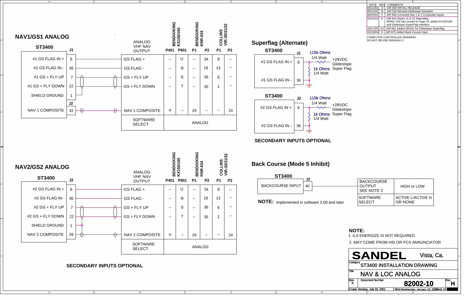
A
A
B
B
C
C
D
D
E
E
4 4
3 3
2 2
1 1
Title
Size Document Number Rev
Create: Sheet of
Category
Mod:Monday, July 02, 200182002-10 H
NAV & LOC ANALOG
SANDEL Vista, Ca.
B
14
ST3400 INSTALLATION DRAWING
Wednesday, January 15, 2014
Title
Size Document Number Rev
Create: Sheet of
Category
Mod:Monday, July 02, 200182002-10 H
NAV & LOC ANALOG
SANDEL Vista, Ca.
B
14
ST3400 INSTALLATION DRAWING
Wednesday, January 15, 2014
Title
Size Document Number Rev
Create: Sheet of
Category
Mod:Monday, July 02, 200182002-10 H
NAV & LOC ANALOG
SANDEL Vista, Ca.
B
14
ST3400 INSTALLATION DRAWING
Wednesday, January 15, 2014
COMMENTSA
REV04/11/02
DATEA/R 484 INITIAL RELEASE
05/21/02 B A/R 525 Revised Glideslope Deviation09/25/02 C A/R 564 Corrected Nav 1 & 2 Composite Inputs02/21/03 D A/R 610 Depict J1 & J2 Seperately
COMPUTER CONTROLLED DRAWINGDO NOT REVISE MANUALLY
ARINC 429 Nav moved to Page 15, added KX155/165and Glideslope SuperFlag interface.
#1 GS FLAG IN -
ST3400 J1
#1 GS FLAG IN + 6
36
#1 GS + FLY UP
#1 GS + FLY DOWN 22
7
GS FLAG +
ANALOGVHF NAVOUTPUT
GS FLAG -
SHIELD GROUND 1
SOFTWARESELECT
GS + FLY UP
GS + FLY DOWN
#2 GS FLAG IN -
ST3400 J2
#2 GS FLAG IN +
22
6
36
7#2 GS + FLY UP
#2 GS + FLY DOWN
28NAV 2 COMPOSITE
GS FLAG +
ANALOGVHF NAVOUTPUT
GS FLAG -
NAV 2 COMPOSITE
1SHIELD GROUND
SOFTWARESELECT
GS + FLY UP
GS + FLY DOWN
SECONDARY INPUTS OPTIONAL
ANALOG
S
T
U
R
BEND
IX/K
ING
KX15
5/16
5
P401 P901
_
_
_
_
36
35
34
18
BEND
IX/K
ING
KNR-
634
P1 P2
_
_
_
_
_9
13
P1
_
P2
COLL
INS
VIR-
30/3
1/32
1_
_5
J2NAV 1 COMPOSITE 42 NAV 1 COMPOSITE _ _29 24_H
ANALOG
S
T
U
R
BEND
IX/K
ING
KX15
5/16
5P401 P901
_
_
_
_
36
35
34
18BE
NDIX
/KIN
GKN
R-63
4
P1 P2
_
_
_
_
_9
13
P1
_
P2
COLL
INS
VIR-
30/3
1/32
1_
_5
_29 _ 24_H
+28VDCGlideslopeSuper Flag
J1ST3400
6
36#1 GS FLAG IN -
#1 GS FLAG IN +
1/4 Watt
1/4 Watt
+28VDCGlideslopeSuper Flag
ST3400
6
36#2 GS FLAG IN -
#2 GS FLAG IN +
1/4 Watt
1/4 WattJ2
SECONDARY INPUTS OPTIONAL
NOTE:1. ILS ENERGIZE IS NOT REQUIRED.
10/17/03 G1 A/R 661 Added 28VDC for Glideslope Superflag
J240BACKCOURSE INPUT
ST3400BACKCOURSEOUTPUT
SOFTWARESELECTImplemented in software 3.00 and laterNOTE:
HIGH or LOW
02/18/04 H A/R 675 Added Back Course Input
ACTIVE L/ACTIVE HOR NONE
SEE NOTE 2
2. MAY COME FROM HSI OR FCS ANNUNCIATOR
Back Course (Mode 5 Inhibit)
Superflag (Alternate)NAV1/GS1 ANALOG
NAV2/GS2 ANALOG
1k Ohms1k Ohms
115k Ohms115k Ohms
1k Ohms1k Ohms
115k Ohms115k Ohms

A
A
B
B
C
C
D
D
E
E
4 4
3 3
2 2
1 1
Title
Size Document Number Rev
Create: Sheet of
Category
Mod:Monday, July 02, 200182002-10 E
NAV & LOC ARINC 429
SANDEL Vista, Ca.
B
15
ST3400 INSTALLATION DRAWING
Wednesday, January 15, 2014
Title
Size Document Number Rev
Create: Sheet of
Category
Mod:Monday, July 02, 200182002-10 E
NAV & LOC ARINC 429
SANDEL Vista, Ca.
B
15
ST3400 INSTALLATION DRAWING
Wednesday, January 15, 2014
Title
Size Document Number Rev
Create: Sheet of
Category
Mod:Monday, July 02, 200182002-10 E
NAV & LOC ARINC 429
SANDEL Vista, Ca.
B
15
ST3400 INSTALLATION DRAWING
Wednesday, January 15, 2014
COMMENTSREVDATEE02/21/03
COMPUTER CONTROLLED DRAWINGDO NOT REVISE MANUALLY
AR 610 Nav ARINC 429 interface moved from original sheet 8. Added VIR 432, Garmin 430/530.
36 42
GARMINGNS-430P4006
NAV 429 A TX
21
SOFTWARESELECT
21
SECONDARY INPUTS OPTIONAL
#2 NAV 429 AIN
GARMINGNS-530P5006ST3400
#2 NAV 429 BIN
35
23
NAV 429 A TX
ARINC 429
41 24
NAV 429 B TX
35
ARINC 429
35
24
J2 S
ECO
NDAR
Y
COLLINS VIR432 P1
KINGKN40P403
#1 NAV 429 BIN 36
GARMINGNS-530P5006
24
NAV 429 B TX
41
42
1
23
SHIELD GROUND
#1 NAV 429 AIN
SHIELD GROUND
KINGKN40P403
1
23
J1 P
RIM
ARY
ST3400
35 24
SOFTWARESELECT
COLLINS VIR432 P1
GARMINGNS-430P4006
23
NAV1/GS1 429
NAV2/GS2 429

A
A
B
B
C
C
D
D
E
E
4 4
3 3
2 2
1 1
Title
Size Document Number Rev
Create: Sheet of
Category
Mod:Monday, July 02, 200182002-10 J
AIRDATA ANALOG
SANDEL Vista, Ca.
B
16
ST3400 INSTALLATION DRAWING
Wednesday, January 15, 2014
Title
Size Document Number Rev
Create: Sheet of
Category
Mod:Monday, July 02, 200182002-10 J
AIRDATA ANALOG
SANDEL Vista, Ca.
B
16
ST3400 INSTALLATION DRAWING
Wednesday, January 15, 2014
Title
Size Document Number Rev
Create: Sheet of
Category
Mod:Monday, July 02, 200182002-10 J
AIRDATA ANALOG
SANDEL Vista, Ca.
B
16
ST3400 INSTALLATION DRAWING
Wednesday, January 15, 2014
COMMENTSA
REV04/11/02
DATEA/R 484 INITIAL RELEASE
B06/21/02 A/R 547 ADDED OAT
NOTES:1.
02/21/03 C A/R 610 Depict J1 & J2 SeperatelyF04/14/03 A/R 626 Moved OAT to Page 18H02/18/04 A/R 675 Corrected pinout callouts on AZ-241.
Removed #2 Analog Airdata & added Penny &Giles D60286
2. See Manufacturer's Manual for Complete Interconnect
See Section 3, Interface Functions for OATProbe Requirements
Airdata Analog For GPWS Only(No Altitude)
3. Pressure Altitude Tolerance: Altitude +/- 500'; for1000' change in altitude tolerance +/-100'
H103/17/04 A/R 690 Added note on Pressure Altitude and interface for the AZ-600.
SIGNAL COMMON
ALTITUDE RATE OUT
1
C
F
TA1 "TYPE 3"
1
TA1 "TYPE 3"
VS SIG IN
10
5
ST3400
INDICATED AIRSPEED H25
PENNY & GILES D60286
PRESSURE ALTITUDEANALOG (Note 3)
40
SHIELD GROUND
BAROMETRIC ALTITUDE
VALID "HIGH"
J1
AIRDATA VALID IN
J1
SOFTWARESELECT
6
39
AIRDATA VALID IN
SHIELD GROUND
E
1
CIC
AIRDATA VALID OUT
TAS SIG IN
CBA "CIC 8800M"
7
CBA "P&G 20V PA"
39
BAROMETRIC ALTITUDE
J2
ST3400 (Mod A Only) 04077 MOD 3
ALTITUDE RATECOMMON
25
38
SHIELD GROUND
CIC Airdata Analog ForGPWS Only (No Altitude)
G
BR1 "CIC BR+10V"SOFTWARESELECT
VALID "HIGH"
BR1 "P&G ANALOG"
K
AIRDATA VALID OUT
VS SIG IN
J2
10
40
INDICATED AIRSPEED
SIGNAL COMMON
ALTITUDE PATE OUT
8
PRESSURE ALTITUDEANALOG (Note 3)
TAS SIG IN
12
66
31
Honeywell AnalogWith Altitude
64
ALT 1 FINE Y
37ALT 1 FINE X
BR1 "ANALOG"
52
ALT 1 FINE SIN 26
AIRDATA VALID OUT
10
8
40
AIRDATA VALID IN
ALT DC COARSE IN
9
TA1 "TYPE 2"
TAS REF IN
ALT/VS1 GND SENSE
40
_TAS REF OUT
VS REF- OUT
TA1 "TYPE 2"
29
TAS SIG OUT
VS REF+ IN
AZ-241 P1
39
24
ALT DC COARSE OUT
42
67
VS SIG IN
BR1 "ANALOG"
VS REF+ OUT
1
AZ-600 P1
ALT 1 FINE COS
VS REF- IN
23
VALID "HIGH"
CBA "S/C AC"CBA "S/C AC"
50
J1
34
VS SIG OUT
TAS SIG IN
54
ST3400
65
76
49
HONEYWELL
SOFTWARESELECT
VALID "HIGH"
SHIELD GROUND
25
ALT/VS1 GND SENSE
43
_
38
27
K
U
HONEYWELL AZ-648
J
G
H
J07/01/04 A/R 717 Added interfaces for theHoneywell AZ-648 & CIC 04077 Mod 3.
4. Requires ST3400 Mod A
(See Note 4)
COMPUTER CONTROLLED DRAWINGDO NOT REVISE MANUALLY
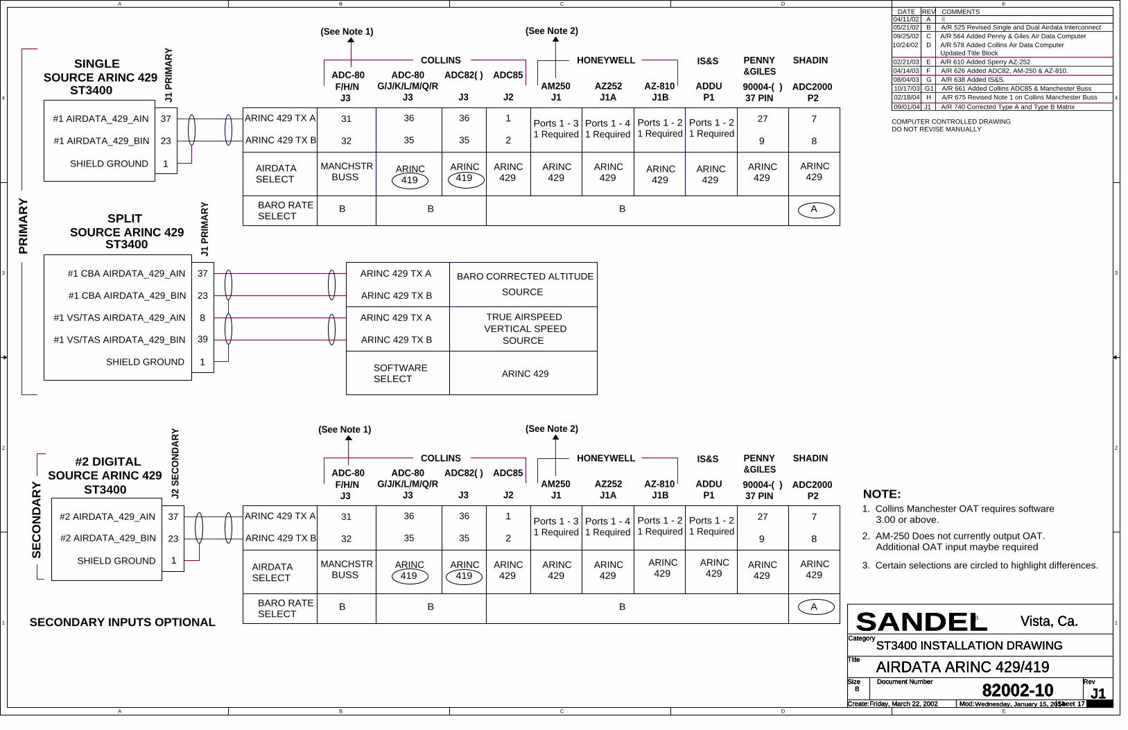
A
A
B
B
C
C
D
D
E
E
4 4
3 3
2 2
1 1
Title
Size Document Number Rev
Create: Sheet of
Category
Mod:Friday, March 22, 200282002-10 J1
AIRDATA ARINC 429/419
SANDEL Vista, Ca.
B
17
ST3400 INSTALLATION DRAWING
Wednesday, January 15, 2014
Title
Size Document Number Rev
Create: Sheet of
Category
Mod:Friday, March 22, 200282002-10 J1
AIRDATA ARINC 429/419
SANDEL Vista, Ca.
B
17
ST3400 INSTALLATION DRAWING
Wednesday, January 15, 2014
Title
Size Document Number Rev
Create: Sheet of
Category
Mod:Friday, March 22, 200282002-10 J1
AIRDATA ARINC 429/419
SANDEL Vista, Ca.
B
17
ST3400 INSTALLATION DRAWING
Wednesday, January 15, 2014
COMMENTSA
REV04/11/02
DATEA/R 484 INITIAL RELEASE
B05/21/02 A/R 525 Revised Single and Dual Airdata Interconnect
09/25/02 C A/R 564 Added Penny & Giles Air Data Computer10/24/02 D A/R 578 Added Collins Air Data Computer
Updated Title Block
COMPUTER CONTROLLED DRAWINGDO NOT REVISE MANUALLY
02/21/03 E A/R 610 Added Sperry AZ-25204/14/03 F A/R 626 Added ADC82, AM-250 & AZ-810.08/04/03 G A/R 638 Added IS&S.
NOTE:1. Collins Manchester OAT requires software 3.00 or above.
2. AM-250 Does not currently output OAT. Additional OAT input maybe required
ST3400
J1 P
RIM
ARY
ARINC 429 TX B
ARINC 429 TX A
SPLITSOURCE ARINC 429
ARINC 429 TX B
ARINC 429 TX A
SOFTWARESELECT ARINC 429
VERTICAL SPEEDTRUE AIRSPEED
BARO CORRECTED ALTITUDESOURCE
SOURCE
ST3400
J1 P
RIM
ARY
SINGLE SOURCE ARINC 429
23
37
23
SHIELD GROUND
#1 AIRDATA_429_AIN
#1 AIRDATA_429_BIN
#2 AIRDATA_429_AIN
#2 AIRDATA_429_BIN
37
23
37
J2 S
ECO
NDAR
Y
#2 DIGITAL SOURCE ARINC 429
1
32
31
ST3400
SEC
ON
DA
RY
SECONDARY INPUTS OPTIONAL
SHIELD GROUND 1
39
8
1SHIELD GROUND
#1 CBA AIRDATA_429_AIN
#1 CBA AIRDATA_429_BIN
#1 VS/TAS AIRDATA_429_AIN
#1 VS/TAS AIRDATA_429_BIN
AZ252 J1A
36
35
ARINC 419
(See Note 2)
ARINC 429
AZ-810 J1B
ARINC 429
ARINC 429
HONEYWELL
Ports 1 - 21 Required
Ports 1 - 41 Required
Ports 1 - 31 Required
9
27
ARINC 429
90004-( ) 37 PIN
8
7
ARINC 429
SHADINIS&S
1
2
ADC82( )
ARINC 429
ADC-80F/H/N J3
36
35
ARINC 419
J3 J2
COLLINSADC85
AM250 J1
ADDU P1
G/J/K/L/M/Q/R J3
ARINC 429
Ports 1 - 21 Required
ADC2000 P2
ADC-80PENNY&GILES
AIRDATASELECT
32
31
MANCHSTR BUSS
AZ252 J1A
36
35
ARINC 419
ARINC 429 TX A
ARINC 429 TX B
(See Note 2)
ARINC 429
AZ-810 J1B
ARINC 429
ARINC 429
HONEYWELL
Ports 1 - 21 Required
Ports 1 - 41 Required
Ports 1 - 31 Required
9
27
ARINC 429
90004-( ) 37 PIN
8
7
ARINC 429
SHADINIS&S
1
2
ADC82( )
ARINC 429
ADC-80F/H/N J3
36
35
ARINC 419
J3 J2
COLLINSADC85
AM250 J1
ADDU P1
G/J/K/L/M/Q/R J3
ARINC 429
Ports 1 - 21 Required
ADC2000 P2
ADC-80PENNY&GILES
ARINC 429 TX B
ARINC 429 TX A
AIRDATASELECT
10/17/03 G1 A/R 661 Added Collins ADC85 & Manchester Buss
PRIM
AR
Y(See Note 1)
(See Note 1)
02/18/04 H A/R 675 Revised Note 1 on Collins Manchester Buss
BARO RATESELECT
B AB B
BARO RATESELECT
B AB B
MANCHSTR BUSS
09/01/04 J1 A/R 740 Corrected Type A and Type B Matrix
3. Certain selections are circled to highlight differences.
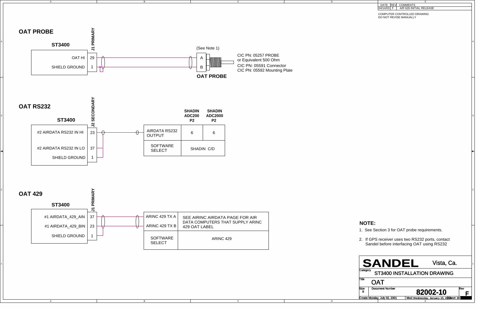
A
A
B
B
C
C
D
D
E
E
4 4
3 3
2 2
1 1
Title
Size Document Number Rev
Create: Sheet of
Category
Mod:Monday, July 02, 200182002-10 F
OAT
SANDEL Vista, Ca.
B
18
ST3400 INSTALLATION DRAWING
Wednesday, January 15, 2014
Title
Size Document Number Rev
Create: Sheet of
Category
Mod:Monday, July 02, 200182002-10 F
OAT
SANDEL Vista, Ca.
B
18
ST3400 INSTALLATION DRAWING
Wednesday, January 15, 2014
Title
Size Document Number Rev
Create: Sheet of
Category
Mod:Monday, July 02, 200182002-10 F
OAT
SANDEL Vista, Ca.
B
18
ST3400 INSTALLATION DRAWING
Wednesday, January 15, 2014
COMMENTSF
REV04/14/03
DATEA/R 626 INITIAL RELEASE
ST3400
J1 P
RIM
ARY
SHIELD GROUND
OAT HI 29
1
CIC PN: 05257 PROBEor Equivalent 500 Ohm
B
A
OAT PROBE
NOTE:1. See Section 3 for OAT probe requirements.
(See Note 1)
COMPUTER CONTROLLED DRAWINGDO NOT REVISE MANUALLY
CIC PN: 05591 ConnectorCIC PN: 05592 Mounting Plate
ST3400
J2 S
ECO
NDAR
Y
AIRDATA RS232OUTPUT
#2 AIRDATA RS232 IN HI 23 6
SHIELD GROUND 1
#2 AIRDATA RS232 IN LO 37 SOFTWARESELECT
SHADIN ADC200 P2
6
SHADIN ADC2000 P2
SHADIN C/D
SEE AIRINC AIRDATA PAGE FOR AIRDATA COMPUTERS THAT SUPPLY ARINC429 OAT LABEL
ARINC 429SOFTWARESELECT
ST3400
J1 P
RIM
ARY
23
SHIELD GROUND
#1 AIRDATA_429_AIN
#1 AIRDATA_429_BIN
37
1
ARINC 429 TX A
ARINC 429 TX B
2. If GPS receiver uses two RS232 ports, contactSandel before interfacing OAT using RS232
OAT PROBE
OAT RS232
OAT 429

A
A
B
B
C
C
D
D
E
E
4 4
3 3
2 2
1 1
Title
Size Document Number Rev
Create: Sheet of
Category
Mod:Monday, July 02, 200182002-10 H
AIRFRAME
SANDEL Vista, Ca.
B
19
ST3400 INSTALLATION DRAWING
Wednesday, January 15, 2014
Title
Size Document Number Rev
Create: Sheet of
Category
Mod:Monday, July 02, 200182002-10 H
AIRFRAME
SANDEL Vista, Ca.
B
19
ST3400 INSTALLATION DRAWING
Wednesday, January 15, 2014
Title
Size Document Number Rev
Create: Sheet of
Category
Mod:Monday, July 02, 200182002-10 H
AIRFRAME
SANDEL Vista, Ca.
B
19
ST3400 INSTALLATION DRAWING
Wednesday, January 15, 2014
ST3400
14
44
LGEAR DOWN IN
FLAPS (See Note 1)
ST3400
14
44
LGEAR DOWN IN28VDC
28VDC
NOT REQUIRED. USE ONLY IFPRESENT INAIRCRAFT.
NOT REQUIRED. USE ONLY IFPRESENT INAIRCRAFT.
AUTOPILOT ENGAGE OUTPUT 28VDC29
AUTOPILOT ENGAGE OUTPUT LOWAP ENGAGE IN
NOT REQUIRED. USE ONLY IFPRESENT INAIRCRAFT.
AP ENGAGE IN
J2ST3400
ST3400
29
NOT REQUIRED. USE ONLY IFPRESENT INAIRCRAFT.
AUTOPILOT SYSTEM
AUTOPILOT SYSTEM
COMMENTSA
REV04/11/02
DATEA/R 484 INITIAL RELEASE
COMPUTER CONTROLLED DRAWINGDO NOT REVISE MANUALLY
J1
A/R 626 Added XYZ Flap InputF04/14/03A/R 661 Added Windshield Wiper InputG110/17/03
WINDSHIELDWIPER
WINDWSHIELD WIPER OUTPUT 28VDC43
NOT REQUIRED. USE ONLY IFPRESENT INAIRCRAFT.
J2
J2ST3400
ST3400
43
NOT REQUIRED. USE ONLY IFPRESENT INAIRCRAFT.
SOFTWARESELECT
SOFTWARESELECT
VALID LO
VALID HI
WINDSHIELDWIPER
WINDWSHIELD WIPER OUTPUT LOW
WINDSHIELD WIPER SYSTEM
WINDSHIELD WIPER SYSTEM
SOFTWARESELECTVALID LO
SOFTWARESELECTVALID HI
SOFTWARESELECTVALID LO
VALID HI
SOFTWARESELECT
ST3400
FLAPS Y
FLAPS X
27
FLAP SYSTEM INPUT
41 FLAP X
FLAP Y
Note: Z must be grounded to airframe.
J2
J2
J2
A/R 675 Changed Flap X/Y Input. Note removedH02/18/04
Gear/Flap Discrete - Valid Low
AP Engage - Valid Low
AP Engage - Valid High
Note: For Gear/Flaps, any combination is permissible.
FLAPS (See Note 1)
Note:1. The assertion of the flaps signal may be selected to
indicate "flaps in landing configuration" or "flaps NOT inlanding configuration". See Airframe maintenancepage.
Flaps - XYZ
Gear/Flap Discrete - Valid High WIPER - Valid Low
WIPER - Valid Low
SOFTWARESELECT
XYZ (Also select Angle of Actuation)
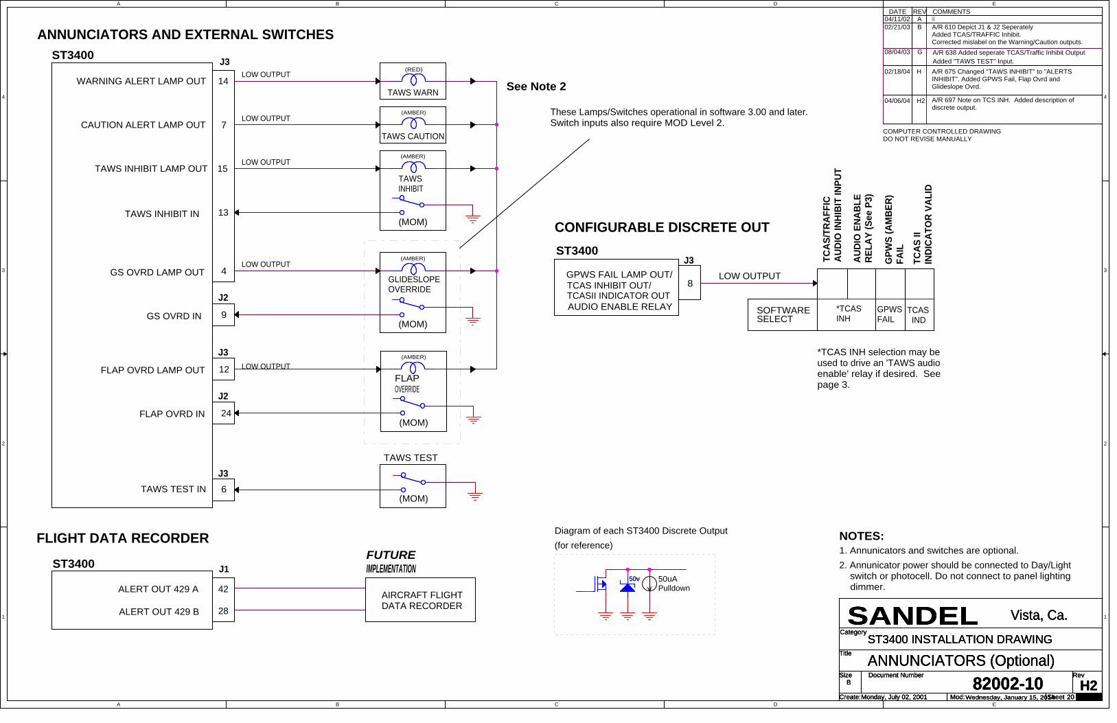
A
A
B
B
C
C
D
D
E
E
4 4
3 3
2 2
1 1
Title
Size Document Number Rev
Create: Sheet of
Category
Mod:Monday, July 02, 200182002-10 H2
ANNUNCIATORS (Optional)
SANDEL Vista, Ca.
B
20
ST3400 INSTALLATION DRAWING
Wednesday, January 15, 2014
Title
Size Document Number Rev
Create: Sheet of
Category
Mod:Monday, July 02, 200182002-10 H2
ANNUNCIATORS (Optional)
SANDEL Vista, Ca.
B
20
ST3400 INSTALLATION DRAWING
Wednesday, January 15, 2014
Title
Size Document Number Rev
Create: Sheet of
Category
Mod:Monday, July 02, 200182002-10 H2
ANNUNCIATORS (Optional)
SANDEL Vista, Ca.
B
20
ST3400 INSTALLATION DRAWING
Wednesday, January 15, 2014
COMMENTSA
REV04/11/02
DATE
02/21/03 B A/R 610 Depict J1 & J2 SeperatelyAdded TCAS/TRAFFIC Inhibit. Corrected mislabel on the Warning/Caution outputs.
G08/04/03 A/R 638 Added seperate TCAS/Traffic Inhibit Output
A/R 484 INITIAL RELEASE
Added "TAWS TEST" Input.
1. Annunicators and switches are optional.NOTES:
WARNING ALERT LAMP OUT
CAUTION ALERT LAMP OUT
14
7
TAWS WARN
(RED)
ST3400FUTUREIMPLEMENTATION
ST3400 J3
TAWS INHIBIT LAMP OUT 15
LOW OUTPUT
(AMBER)
TAWS TEST IN
TAWS TEST
(MOM)
GS OVRD LAMP OUT 4
FLAP OVRD LAMP OUT
GS OVRD IN
FLAP OVRD IN
These Lamps/Switches operational in software 3.00 and later.Switch inputs also require MOD Level 2.
TAWS INHIBIT IN
COMPUTER CONTROLLED DRAWINGDO NOT REVISE MANUALLY
H2
A/R 675 Changed "TAWS INHIBIT" to "ALERTSINHIBIT". Added GPWS Fail, Flap Ovrd andGlideslope Ovrd.
J1
42
28ALERT OUT 429 B
ALERT OUT 429 A AIRCRAFT FLIGHTDATA RECORDER
GPWS FAIL LAMP OUT/8
LOW OUTPUT
2. Annunicator power should be connected to Day/Light switch or photocell. Do not connect to panel lighting dimmer.
J3ST3400
See Note 2
TCAS
IIIN
DICA
TOR
VALI
D
GPW
S (A
MBE
R)FA
IL
TCAS INHIBIT OUT/TCASII INDICATOR OUT
SOFTWARESELECT
6
J3
J2
9
J3
12
J2
24
FLAPOVERRIDE
(MOM)
(AMBER)
GLIDESLOPEOVERRIDE
(AMBER)
(MOM)
(AMBER)
(MOM)
TAWSINHIBIT
13
TAWS CAUTION
LOW OUTPUT
LOW OUTPUT
LOW OUTPUT
LOW OUTPUT
ANNUNCIATORS AND EXTERNAL SWITCHES
FLIGHT DATA RECORDER
CONFIGURABLE DISCRETE OUT
GPWS FAIL
TCAS IND
AUDIO ENABLE RELAY
*TCAS INH selection may beused to drive an 'TAWS audioenable' relay if desired. Seepage 3.
02/18/04
04/06/04
H
A/R 697 Note on TCS INH. Added description ofdiscrete output.
*TCASINH
TCAS
/TRA
FFIC
AUDI
O IN
HIBI
T IN
PUT
AUDI
O E
NABL
ERE
LAY
(See
P3)
50uAPulldown
Diagram of each ST3400 Discrete Output(for reference)
50v 50v

A
A
B
B
C
C
D
D
E
E
4 4
3 3
2 2
1 1
Title
Size Document Number Rev
Create: Sheet of
Category
Mod:Monday, July 02, 200182002-10 A1
INTERLINK
SANDEL Vista, Ca.
B
21
ST3400 INSTALLATION DRAWING
Wednesday, January 15, 2014
Title
Size Document Number Rev
Create: Sheet of
Category
Mod:Monday, July 02, 200182002-10 A1
INTERLINK
SANDEL Vista, Ca.
B
21
ST3400 INSTALLATION DRAWING
Wednesday, January 15, 2014
Title
Size Document Number Rev
Create: Sheet of
Category
Mod:Monday, July 02, 200182002-10 A1
INTERLINK
SANDEL Vista, Ca.
B
21
ST3400 INSTALLATION DRAWING
Wednesday, January 15, 2014
PILOTST3400
COPILOTST3400
J2 S
ECO
NDAR
Y
J2 S
ECO
NDAR
Y
INTERLINK_429_A TX
INTERLINK_429_B TX
INTERLINK_429_A RX
INTERLINK_429_B RX
41
27
30
15
1
27
41
15
30
SHIELD GROUND
INTERLINK_429_A RX
INTERLINK_429_B TX
INTERLINK_429_B RX
INTERLINK_429_A TX
COMMENTSA
REVDATEA/R 484 INITIAL RELEASE
COMPUTER CONTROLLED DRAWINGDO NOT REVISE MANUALLY
(Connection Recommended for Dual installs)
04/11/0202/24/04 A Add note
DUAL SYSTEM INTERLINK
FUTURE IMPLEMENTATION

A
A
B
B
C
C
D
D
E
E
4 4
3 3
2 2
1 1
Title
Size Document Number Rev
Create: Sheet of
Category
Mod:Thursday, November 06, 200382002-10 J
TCAS / TRAFFIC
SANDEL Vista, Ca.
B
22
ST3400 INSTALLATION DRAWING
Wednesday, January 15, 2014
Title
Size Document Number Rev
Create: Sheet of
Category
Mod:Thursday, November 06, 200382002-10 J
TCAS / TRAFFIC
SANDEL Vista, Ca.
B
22
ST3400 INSTALLATION DRAWING
Wednesday, January 15, 2014
Title
Size Document Number Rev
Create: Sheet of
Category
Mod:Thursday, November 06, 200382002-10 J
TCAS / TRAFFIC
SANDEL Vista, Ca.
B
22
ST3400 INSTALLATION DRAWING
Wednesday, January 15, 2014
COMMENTSH
REV02/18/04
DATEA/R 675 INITIAL RELEASE
TCAS/TRAFFIC 429 A INPUT
SHIELD GROUND8
7
GOODRICH TCAS 791/AJ2
1322 ARINC 429 TX A
ARINC 429 TX BTCAS/TRAFFIC 429 B INPUT
13
TEST/ALT
OPER/STBY
SOFTWARE SELECT
1. "GOODRICH TCAS 791/A"29
49 GROUND
ON/OFF CONTROL32
TCAS 791/A SETUP
DISPLAY TYPE: SET TO"ARINC735 TYPE II"
P1
2. See Manufacturers Installation Manuals for complete wiring interface.
NOTES:1. Interconnect shown with Sandel ST3400 as primary Traffic display
J3
8TCAS INH 9 GPWS AUDIO INHIBIT
P2
3. ST3400 P3-8 Output is configured on Maintenance Page 2 (System).
TCAS 791
2. P3-8: TCAS INH
TCAS/TRAFFIC 429 A INPUT
SHIELD GROUND16
30
HONEYWELL CAS66J2
1322 ARINC 429 TX A
ARINC 429 TX BTCAS/TRAFFIC 429 B INPUT
SOFTWARE SELECT
1. "HONEYWELL CAS 66"
P1B
J3
8TCAS INH (secondary)TCAS IND (primary) 34 TA VALID 1*
CAS66
2. SEE ABOVE
Use P3-8 as TCAS INH todrive relay unless ST3400 isprimary indicator.
7CAUTIONWARN 14
TCAS PWR
Use this relay tomute TCAS audioper TCASinstallationmanual
ST3400
ST3400
PWR
(MOM)
(MOM)
04/06/04 H2 A/R 697 P3-8 Selection now "AUDIO ENA" instead of TCAS INHto allow operation during maintenance.
If Primary
If P
rimar
y
If no
t prim
ary
08/05/04 J A/R 717 GOODRICH SKYWATCH P1 PIN 5 WAS 49
4
TCAS INH
J3
19
ARINC 429 TX A
1. "RYAN 900BX TAS"
1
ST3400 Ryan TCAD 9900BX
SHIELD GROUND 1
TEST/ALT
ARINC 429 TX B
TCAD Power
9
AUDIO PANEL
2. P3-8: TCAS INH
ARINC 429 TX A
2
P1
TCAS/TRAFFIC 429 B INPUT
34
STBY/OPER
3
8
ON/OFF CONTROL
SOFTWARE SELECT
J3
SOFTWARE SELECTIONSGROUND
43
TCAS/TRAFFIC 429 A INPUT
TCAS INH
(MOM)
COMPUTER CONTROLLED DRAWINGDO NOT REVISE MANUALLY
DISPLAY TYPE "STANDARD TYPE 5"
10
32TCAS/TRAFFIC 429 B INPUT
RYAN TCAD
GOODRICH SKYWATCH HP
GROUND
(MOM)
J2
J2
1. "GOODRICH SKYWATCH HP"
32
SKYWATCH HP
5
21
AUDIO OUT
PWR
ST3400
SHIELD GROUND
GPWS AUDIO INHIBIT
P1
2 42
SKYWATCH HP SETUP
8
2. P3-8: TCAS INH
ARINC 429 TX B
TCAS/TRAFFIC 429 A INPUT
8

A
A
B
B
C
C
D
D
E
E
4 4
3 3
2 2
1 1
Title
Size Document Number Rev
Create: Sheet of
Category
Mod:Wednesday, January 15, 201482002-10 A
Garmin GTN-6XX/7XX Series
SANDEL Vista, Ca.
B
23
ST3400 INSTALLATION DRAWINGTitle
Size Document Number Rev
Create: Sheet of
Category
Mod:Wednesday, January 15, 201482002-10 A
Garmin GTN-6XX/7XX Series
SANDEL Vista, Ca.
B
23
ST3400 INSTALLATION DRAWINGTitle
Size Document Number Rev
Create: Sheet of
Category
Mod:Wednesday, January 15, 201482002-10 A
Garmin GTN-6XX/7XX Series
SANDEL Vista, Ca.
B
23
ST3400 INSTALLATION DRAWING
COMPUTER CONTROLLED DRAWINGDO NOT REVISE MANUALLY
A01/20/14 AR1356 INITIAL RELEASE
DATE REV COMMENTS
GPS ARINC 429 A OUT
GPS ARINC 429 B OUT
VLOC ARINC 429 A OUT
VLOC ARINC 429 B OUT
RS232 TX
RS232 GND
Select Channel 1 or 2 in GTN 6XXSeries. GTN 7XX series has additional channel 3.
P1004-24 for GTN6XX/7XX
P1004-23 for GTN6XX/7XX
Select one of the 4 RS232 TX outputs.A channel needs to be dedicated tothe ST3400. GTN7XX series hasadditional channels 5 & 6 on P1005.
#1 FMS 429 A IN
#1 FMS 429 B IN
#1 NAV 429 B IN
#1 NAV 429 A IN
#1 NAV RS232 IN
SIGNAL GND
J1
31
17
35
21
11
1
GPS/FMS 1
ST3400Garmin GTN-6XX/7XX Series
1) Refer to current Installation Manual for GarminGTN-6XX/7XX for ARINC 429 and RS232 pins.
2) Garmin GTN setup: "Select GMA FORMAT 3"for the ARINC GPS 429 out. Select High or LowSpeed as desired.
3) When using the RS232 for Altitude, select theChannel that is interfaced to the ST3400 andprogram Output as "EXTERNAL EGPWS"
NOTES UNLESS OTHERWISE SPECIFIED
(GTN-650/750 only)
ST3400Garmin GTN-6XX/7XX Series
(GTN-650/750 only)
GPS/FMS 2
GPS ARINC 429 A OUT
GPS ARINC 429 B OUT
VLOC ARINC 429 A OUT
VLOC ARINC 429 B OUT
RS232 TX
RS232 GND
Select Channel 1 or 2 in GTN 6XXSeries. GTN 7XX series has additional channel 3.
P1004-24 for GTN6XX/7XX
P1004-23 for GTN6XX/7XX
Select one of the 4 RS232 TX outputs.A channel needs to be dedicated tothe ST3400. GTN7XX series hasadditional channels 5 & 6 on P1005.
#2 FMS 429 A IN
#2 FMS 429 B IN
#2 NAV 429 B IN
#2 NAV 429 A IN
#2 NAV RS232 IN
SIGNAL GND
J2
31
17
35
21
11
1
Recommended