BTS3900- Basic Operations and Maintenance Manual.
Created By: Ruchira
@ ATMC Telecom 2010-All rights Reserved.
Disclaimer
This document is subjected to Basic Operation and maintenance procedures for the BTS3900. Use for only ATMC Telecom Employees.
Contents
How to Log in to the NodeB using LMT? ………………………………………………………………… 2
Identifying the LMT Work Areas. ……………………………………………………………………………. 4
How to Check the Alarms of the NodeB? ………………………………………………………………. 5
How to check the status of the hardware using LMT? …………………………………………….. 6
How to check the Traffic of cells? ………………………………………………………………………….. 7
Viewing Basic information of the NodeB ……………………………………………………………….. 8
How to do Basic O & M Operations of NodeB Hardware? ……………………………………. 13
How to Replace NodeB hardware? …………………………………………………………………………14
Preventive Maintenance of the BTS3900. …………………………………………………………….. 16
1
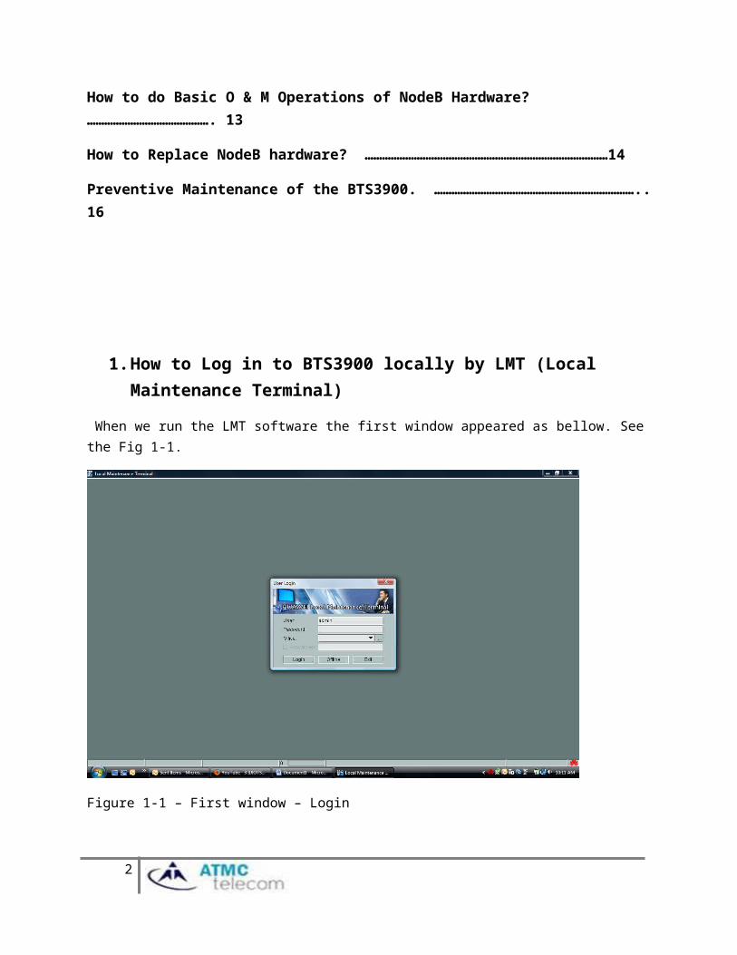
1. How to Log in to BTS3900 locally by LMT (Local Maintenance Terminal)
When we run the LMT software the first window appeared as bellow. See the Fig 1-1.
Figure 1-1 – First window – Login
The figure 1-1 Shown the first window appeared after run the LMT software. We need to set the Default Local Maintenance IP of the NodeB to connect.
When you click the button it will show the default IP configuration window. See the Fig 1-2 bellow
2
Click here to set The Default IP of The NodeB with LMT
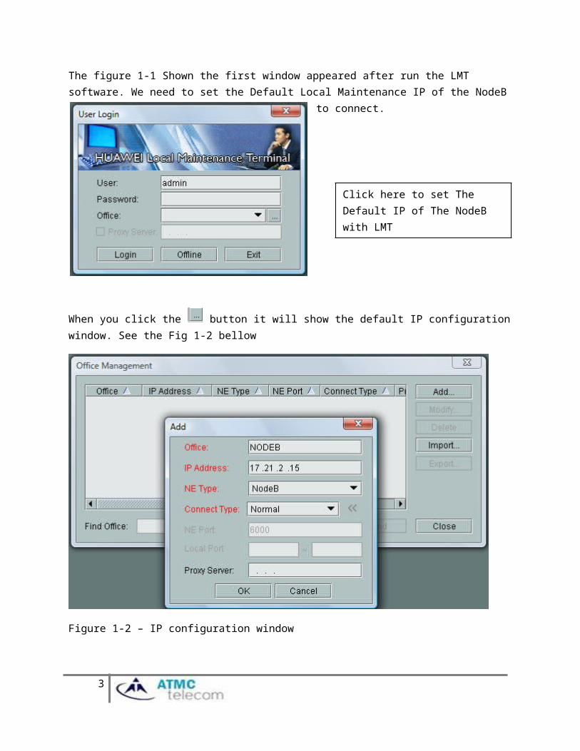
Figure 1-2 – IP configuration window
When click the button, it will show the IP configuration window and enter all information shown in Fig 1-2 to “Add” window.
Then change the IP of the Laptop as follows. See the Fig 1-3.
.
3
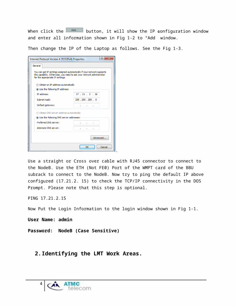
Use a straight or Cross over cable with RJ45 connector to connect to the NodeB. Use the ETH (Not FE0) Port of the WMPT card of the BBU subrack to connect to the NodeB. Now try to ping the default IP above configured (17.21.2. 15) to check the TCP/IP connectivity in the DOS Prompt. Please note that this step is optional.
PING 17.21.2.15
Now Put the Login Information to the login window shown in Fig 1-1.
User Name: admin
Password: NodeB (Case Sensitive)
2. Identifying the LMT Work Areas.There are three important working areas in LMT to Identify. See the Fig 2-1.
4
Objects Plane – This area will shows the objects selected in the Navigation PlaneNavigation Plane- will
allow to navigate the features of LMT
Output plane – Will provide output and alarms while working with Objects
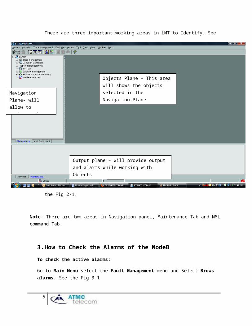
Note: There are two areas in Navigation panel, Maintenance Tab and MML command Tab.
3. How to Check the Alarms of the NodeB
To check the active alarms:
Go to Main Menu select the Fault Management menu and Select Brows alarms. See the Fig 3-1
Figure 3-1
Note: you can use the short cut menu also to open the Alarm browser
5
Alarm Browser Short cut
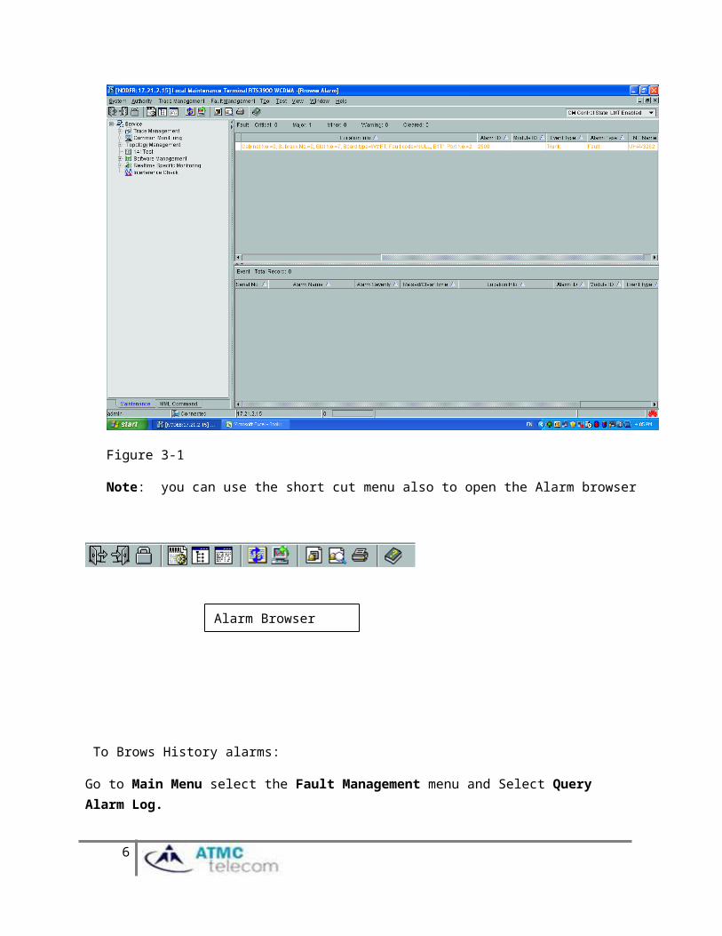
To Brows History alarms:
Go to Main Menu select the Fault Management menu and Select Query Alarm Log.
4. How to check the status of the hardware using LMT?
Go to Maintenance Tab of the Navigation Plane (Bottom Left-hand corner of the LMT Window)
Extract the Topology Management tree
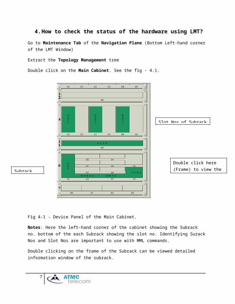
Double click on the Main Cabinet. See the fig - 4.1.
Fig 4-1 - Device Panel of the Main Cabinet.
Notes: Here the left-hand corner of the cabinet showing the Subrack no. bottom of the each Subrack showing the slot no. Identifying Surack Nos and Slot Nos are important to use with MML commands.
Double clicking on the frame of the Subrack can be viewed detailed information window of the subrack.
Right clicking on the boards will give the operation and maintenance functions (reset board, block board)
6
Slot Nos of Subrack 4
Subrack No: 0
Double click here (Frame) to view the detailed subrack window
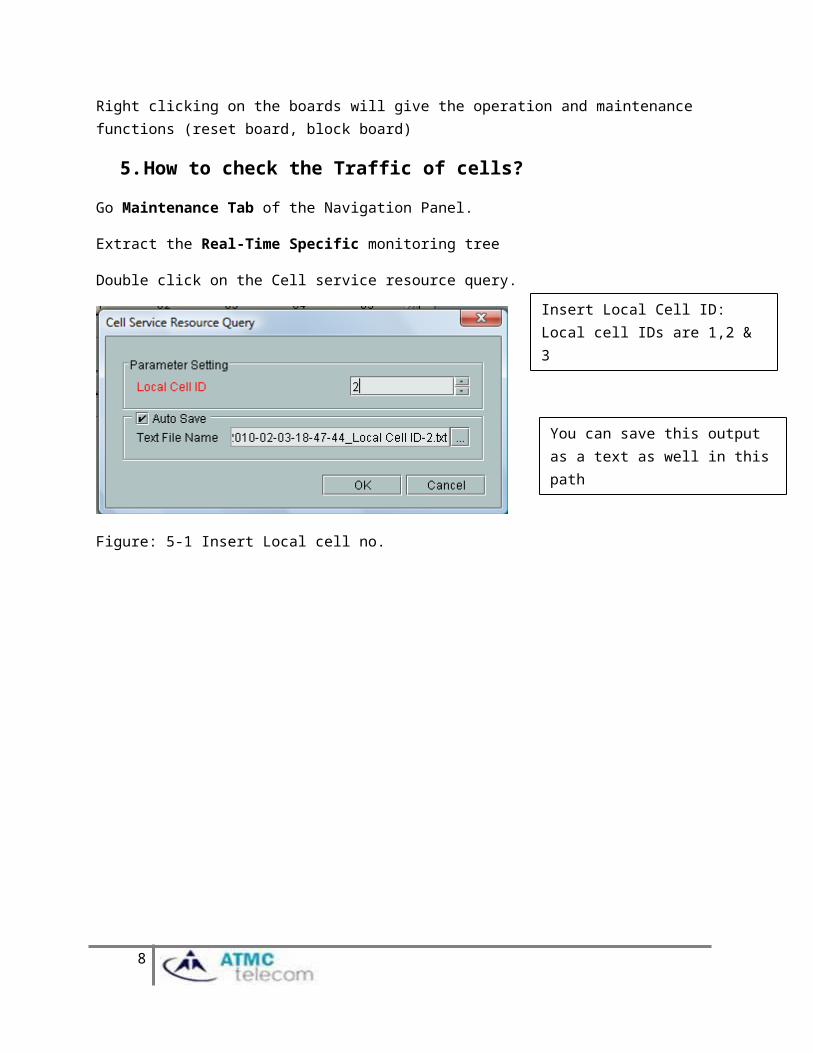
5. How to check the Traffic of cells?
Go Maintenance Tab of the Navigation Panel.
Extract the Real-Time Specific monitoring tree
Double click on the Cell service resource query.
Figure: 5-1 Insert Local cell no.
Figure- 5-2 Output window
7
Insert Local Cell ID: Local cell IDs are 1,2 & 3
You can save this output as a text as well in this path
Note: It is important to check the traffic status of the cell as a PM activity.
MML (Man Machine Language) commands
MML commands will give the configuration capability of the nodeB. We can easily identify the operation of the MML command using the first three letters of the Command.
DSP – Display
LST – List
RST- Reset
BLK-Block
UBL-Unblock
MOD- Modify
ACT –Active
ADD- Add
RMV- Remove
6. Viewing Basic information of the NodeB
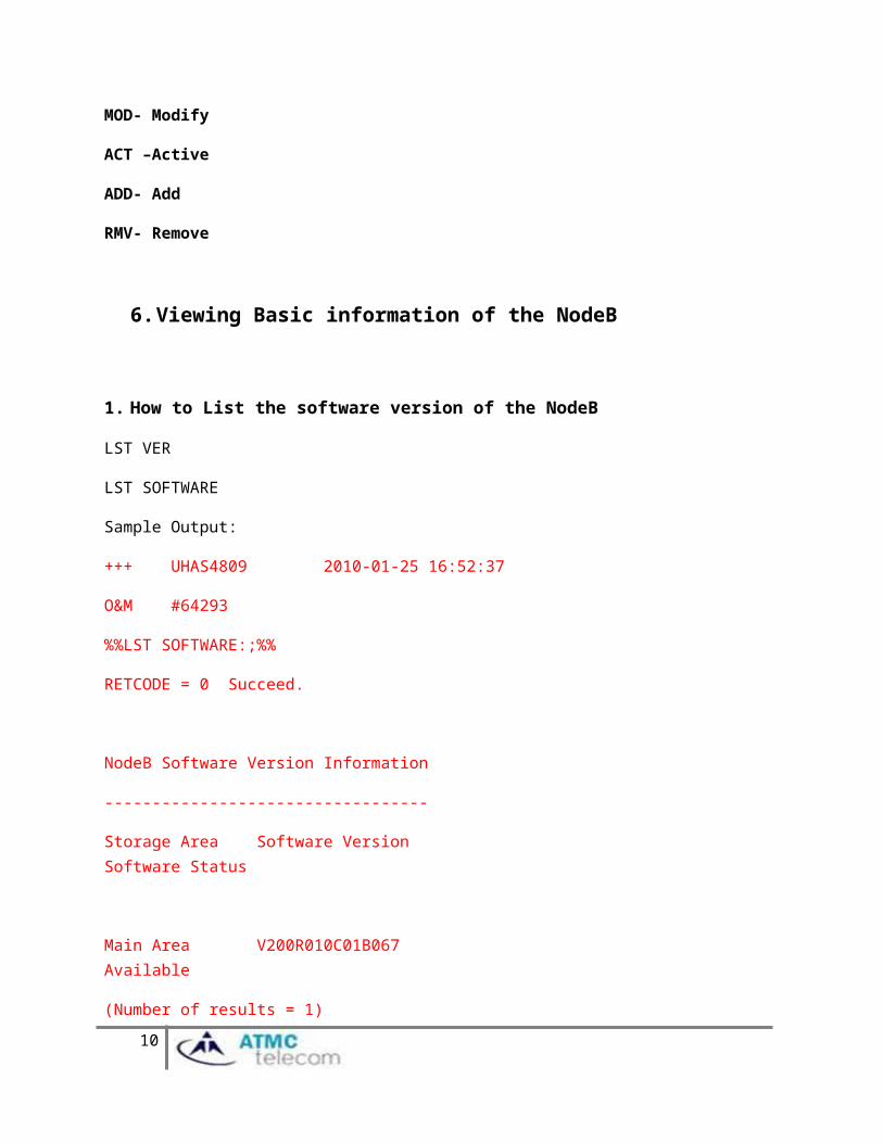
1. How to List the software version of the NodeB
LST VER
LST SOFTWARE
Sample Output:
+++ UHAS4809 2010-01-25 16:52:37
O&M #64293
%%LST SOFTWARE:;%%
RETCODE = 0 Succeed.
8

NodeB Software Version Information
----------------------------------
Storage Area Software Version Software Status
Main Area V200R010C01B067 Available
(Number of results = 1)
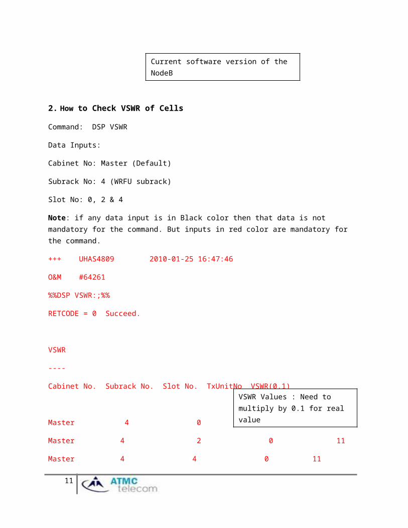
2. How to Check VSWR of Cells
Command: DSP VSWR
Data Inputs:
Cabinet No: Master (Default)
Subrack No: 4 (WRFU subrack)
Slot No: 0, 2 & 4
Note: if any data input is in Black color then that data is not mandatory for the command. But inputs in red color are mandatory for the command.
+++ UHAS4809 2010-01-25 16:47:46
O&M #64261
%%DSP VSWR:;%%
RETCODE = 0 Succeed.
VSWR
----
9
Current software version of the NodeB
Cabinet No. Subrack No. Slot No. TxUnitNo VSWR(0.1)
Master 4 0 0 60
Master 4 2 0 11
Master 4 4 0 11
(Number of results = 3)
--- END
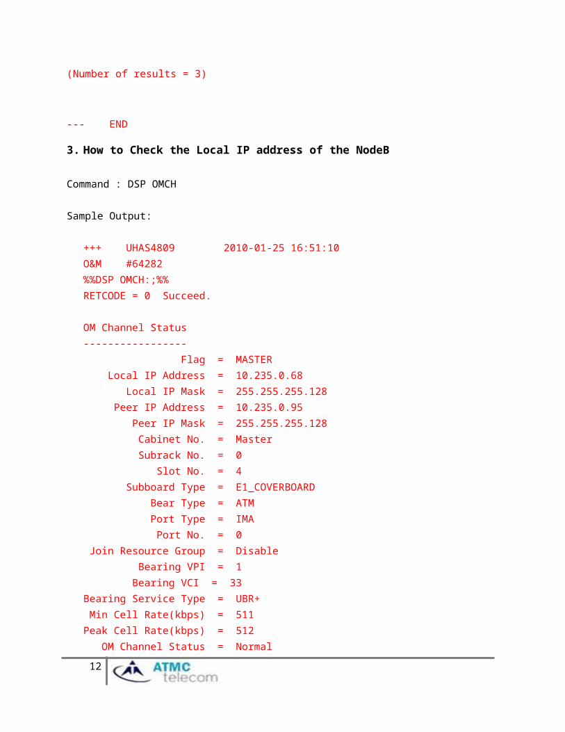
3. How to Check the Local IP address of the NodeB
Command : DSP OMCH
Sample Output:
+++ UHAS4809 2010-01-25 16:51:10 O&M #64282%%DSP OMCH:;%%RETCODE = 0 Succeed.
OM Channel Status----------------- Flag = MASTER Local IP Address = 10.235.0.68 Local IP Mask = 255.255.255.128 Peer IP Address = 10.235.0.95 Peer IP Mask = 255.255.255.128 Cabinet No. = Master Subrack No. = 0 Slot No. = 4 Subboard Type = E1_COVERBOARD Bear Type = ATM Port Type = IMA Port No. = 0 Join Resource Group = Disable Bearing VPI = 1 Bearing VCI = 33
10
VSWR Values : Need to multiply by 0.1 for real value
Bearing Service Type = UBR+ Min Cell Rate(kbps) = 511Peak Cell Rate(kbps) = 512 OM Channel Status = Normal(Number of results = 1)
--- END
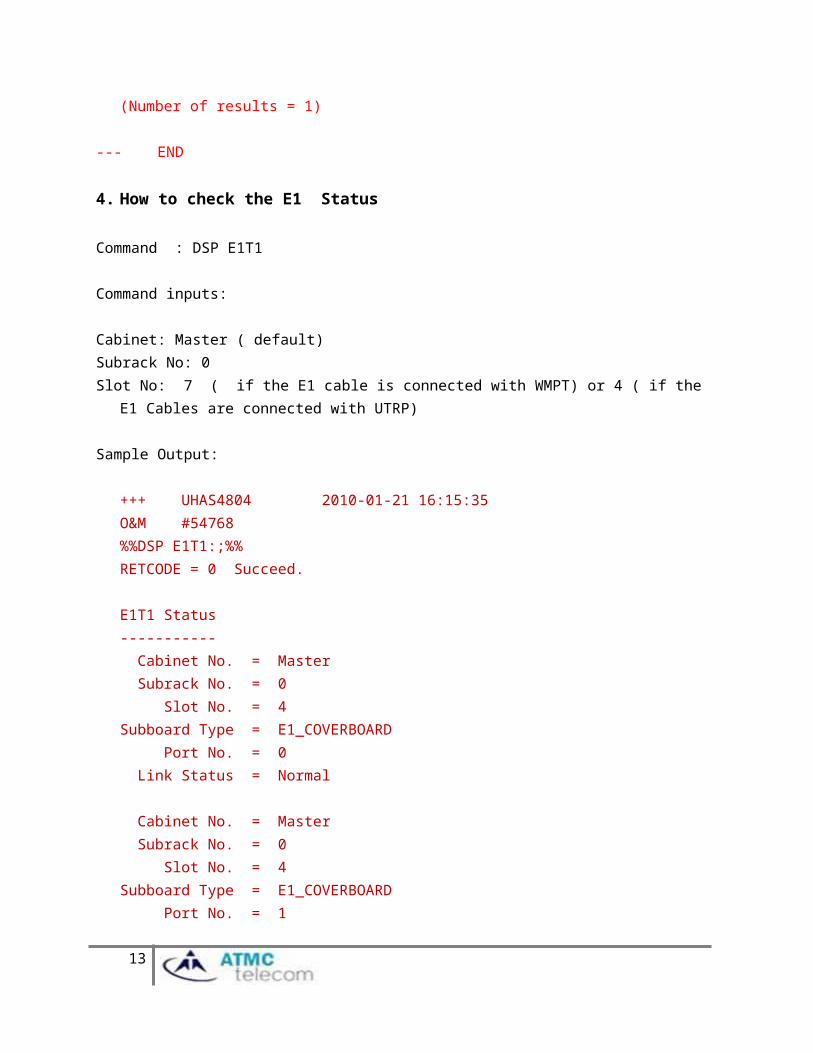
4. How to check the E1 Status
Command : DSP E1T1
Command inputs:
Cabinet: Master ( default)Subrack No: 0Slot No: 7 ( if the E1 cable is connected with WMPT) or 4 ( if the E1 Cables are connected with UTRP)
Sample Output:
+++ UHAS4804 2010-01-21 16:15:35 O&M #54768%%DSP E1T1:;%%RETCODE = 0 Succeed.
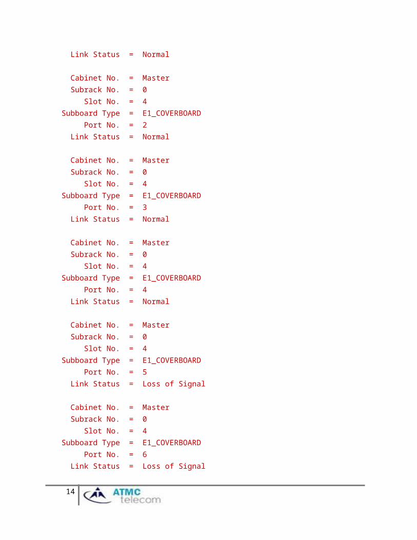
E1T1 Status----------- Cabinet No. = Master Subrack No. = 0 Slot No. = 4Subboard Type = E1_COVERBOARD Port No. = 0 Link Status = Normal
Cabinet No. = Master Subrack No. = 0 Slot No. = 4Subboard Type = E1_COVERBOARD Port No. = 1 Link Status = Normal
11
Cabinet No. = Master Subrack No. = 0 Slot No. = 4Subboard Type = E1_COVERBOARD Port No. = 2 Link Status = Normal
Cabinet No. = Master Subrack No. = 0 Slot No. = 4Subboard Type = E1_COVERBOARD Port No. = 3 Link Status = Normal
Cabinet No. = Master Subrack No. = 0 Slot No. = 4Subboard Type = E1_COVERBOARD Port No. = 4 Link Status = Normal
Cabinet No. = Master Subrack No. = 0 Slot No. = 4Subboard Type = E1_COVERBOARD Port No. = 5 Link Status = Loss of Signal
Cabinet No. = Master Subrack No. = 0 Slot No. = 4Subboard Type = E1_COVERBOARD Port No. = 6 Link Status = Loss of Signal
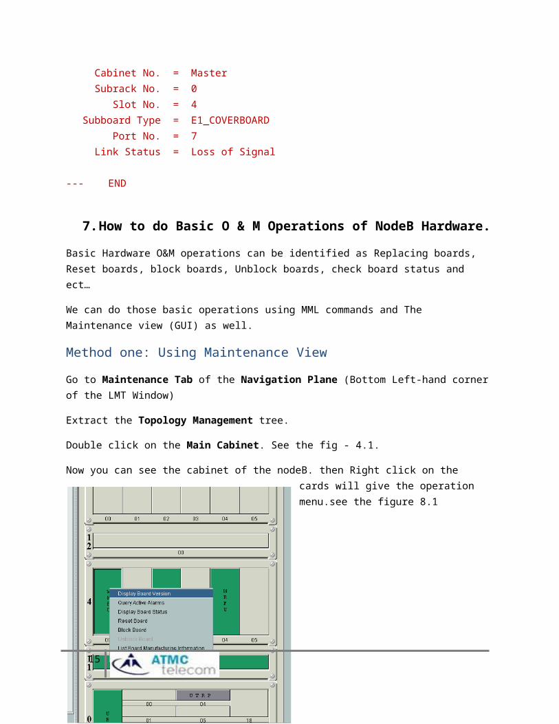
Cabinet No. = Master Subrack No. = 0 Slot No. = 4Subboard Type = E1_COVERBOARD Port No. = 7 Link Status = Loss of Signal
12
--- END
7. How to do Basic O & M Operations of NodeB Hardware.
Basic Hardware O&M operations can be identified as Replacing boards, Reset boards, block boards, Unblock boards, check board status and ect…
We can do those basic operations using MML commands and The Maintenance view (GUI) as well.
Method one: Using Maintenance View
Go to Maintenance Tab of the Navigation Plane (Bottom Left-hand corner of the LMT Window)
Extract the Topology Management tree.
Double click on the Main Cabinet. See the fig - 4.1.
Now you can see the cabinet of the nodeB. then Right click on the cards will give the operation menu.see the figure 8.1
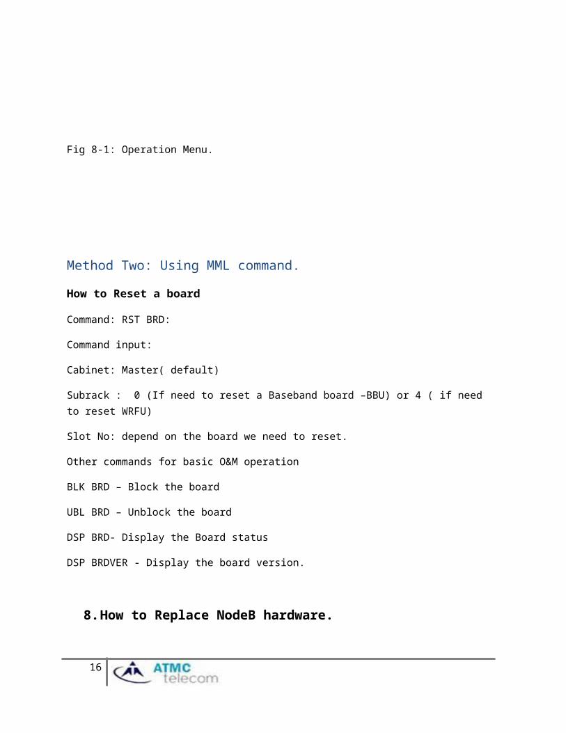
Fig 8-1: Operation Menu.
13
Method Two: Using MML command.
How to Reset a board
Command: RST BRD:
Command input:
Cabinet: Master( default)
Subrack : 0 (If need to reset a Baseband board –BBU) or 4 ( if need to reset WRFU)
Slot No: depend on the board we need to reset.
Other commands for basic O&M operation
BLK BRD – Block the board
UBL BRD – Unblock the board
DSP BRD- Display the Board status
DSP BRDVER - Display the board version.
8. How to Replace NodeB hardware.
1. How to replace a WRFU?
Step 1:
Block the Local cell belongs to WRFU.
Command: BLK LOCELL
Command inputs: Local Cell ID – 1, 2 or 3.
Block PRI: High, Normal or Low.
High – Immediately lock the Cell
Normal: you can give a waiting time interval (waiting for call release)
Low: Will wait for all call released.
14
Step 2:
Block the WRFU
Command: BLK BRD
Command inputs: Cabinet: Master (Default)
Subrack No: 04
Slot No: 0,2 or 4
Step 3:
Replace the Hardware
Step 4:
Unblock the WRFU
Command: UBL BRD
Step5:
Unblock the Local Cell
Command: UBL LOCELL
Note: Need to wait board loading time.
2. How to replace BBU cards.
Replacing WBBP and UTRP procedures are same. When replacing BBU cards will affect whole traffic of the NodeB.
Step 1:
Block three local cells
Command: BLK LOCELL
Step 2:
Block the board
15
Command: BLK BRD
Command inputs:
Subrack No: 0 (BBU subrack)
Slot No: 3 (for WBBP) or 4 (for UTRP)
Step 3:
Unblock the Board.
Command: UBL BRD
Step4:
Unblock the Cells
Command: UBL LOCELL
Note: Need to wait for board loading time.
9. Preventive Maintenance Of the BTS3900
Preventive maintenance scope of the DBS3900 has two parts.
Checking for the physical installation of the outdoor and indoor Back up the Configuration and check the health
Checking the Outdoor and indoor installation is same as other technologies and you can do the same way.
Backup the configuration and Check the health.
How to backup configuration of the NodeB?
Go to Maintenance Tab of the Navigation Plane (Bottom Left-hand corner of the LMT Window)
Extract the Software Management window.
Double click on Data Config file Transfer.
16
Select the Upload and Uncompress
Brows the folder to upload the configuration file.
Press Start.
Note: The file name of the Configuration file is NodeBCfg.xml: This file is very important for troubleshooting with WMPT. This file is stored in the WMPT flash memory. We can download the configuration file in case of WMPT failure and this process is Traffic effecting.
Backup some important information for troubleshooting.
Run the following commands and save the command output file.
MML Script for backup important configuration information.
17
Note: Copy all command from above text file and paste to the window just above the command input lines and press F9. It will run all commands at ones. Now right click on the command output window and Save as a text file.
General Health check of the NodeB.
1. Check the current alarms2. Check history Alarms3. Check VSWR4. Check the traffic of cells.
18
Recommended


![CERTIFICATION REPORT - commoncriteriaportal.org HUAWEI... · [EXT1493] Evaluation Technical Report of Huawei 3900 Series LTE eNodeB ... Agent Description Eavesdropper An eavesdropper](https://img.pdfslide.us/doc/110x75/5b8432ec7f8b9aef498bd1c8/certification-report-huawei-ext1493-evaluation-technical-report-of-huawei.jpg)