NAVEDTRA 14069A 10-19
1.2.6 Conduits and Fittings
An electrical conduit is a pipe, tube, or other means in which electrical wires are installed for protection from the elements or accidental damage. Much like plumbing, the conduit's fittings depend upon the type of pipe or tubing used. Navy construction generally uses rigid, thin-wall, or flexible conduit.
1.2.6.1 Rig id Condu it
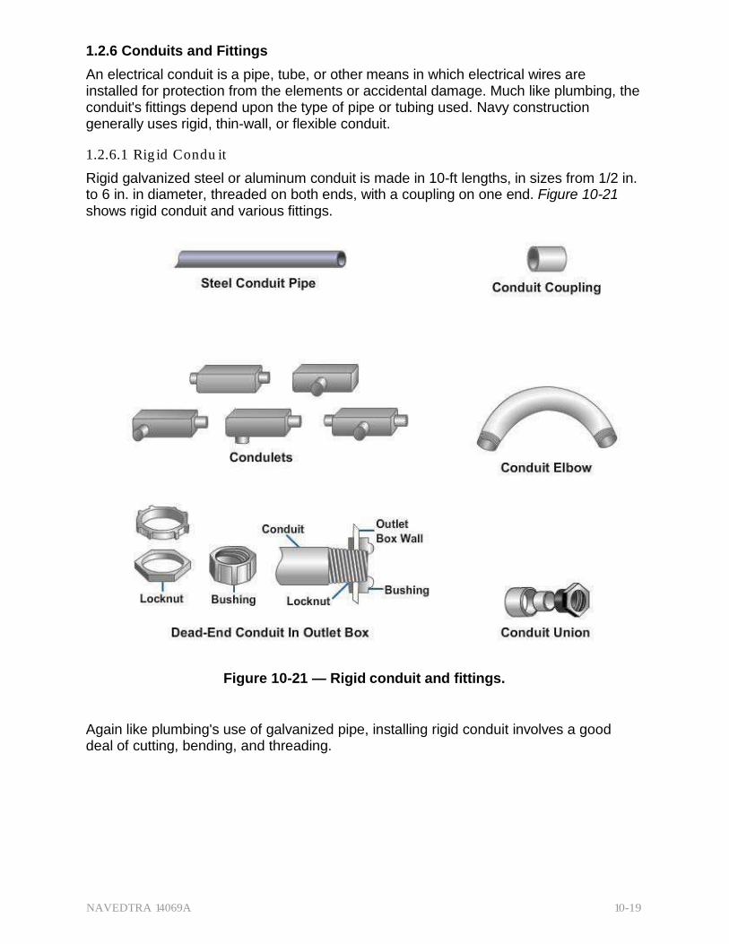
Rigid galvanized steel or aluminum conduit is made in 10-ft lengths, in sizes from 1/2 in. to 6 in. in diameter, threaded on both ends, with a coupling on one end. Figure 10-21 shows rigid conduit and various fittings.
Figure 10-21 — Rigid conduit and fittings.
Again like plumbing's use of galvanized pipe, installing rigid conduit involves a good deal of cutting, bending, and threading.
NAVEDTRA 14069A 10-20
An ordinary hacksaw or special wheel pipe cutter is used for cutting, and a ratchet type of mechanical die is used for threading the cut ends.
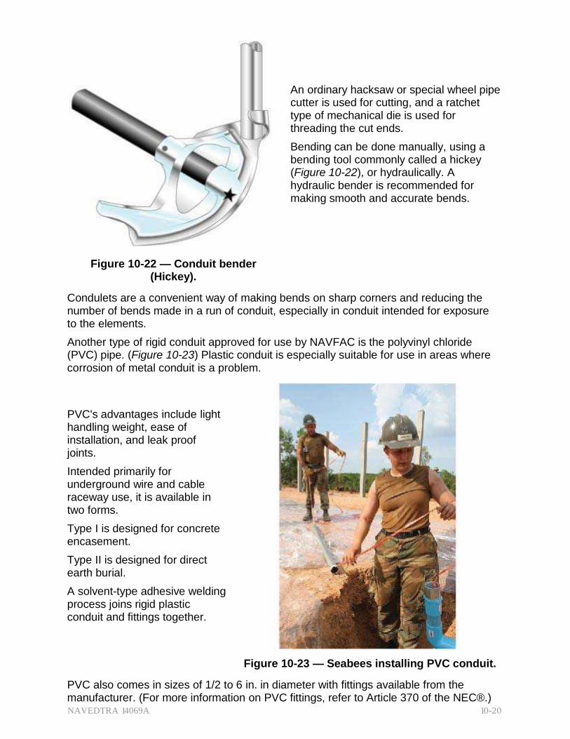
Bending can be done manually, using a bending tool commonly called a hickey (Figure 10-22), or hydraulically. A hydraulic bender is recommended for making smooth and accurate bends.
Figure 10-22 — Conduit bender (Hickey).
Condulets are a convenient way of making bends on sharp corners and reducing the number of bends made in a run of conduit, especially in conduit intended for exposure to the elements.
Another type of rigid conduit approved for use by NAVFAC is the polyvinyl chloride (PVC) pipe. (Figure 10-23) Plastic conduit is especially suitable for use in areas where corrosion of metal conduit is a problem.
PVC's advantages include light handling weight, ease of installation, and leak proof joints.
Intended primarily for underground wire and cable raceway use, it is available in two forms.
Type I is designed for concrete encasement.
Type II is designed for direct earth burial.
A solvent-type adhesive welding process joins rigid plastic conduit and fittings together.
Figure 10-23 — Seabees installing PVC conduit.
PVC also comes in sizes of 1/2 to 6 in. in diameter with fittings available from the manufacturer. (For more information on PVC fittings, refer to Article 370 of the NEC®.)
NAVEDTRA 14069A 10-21
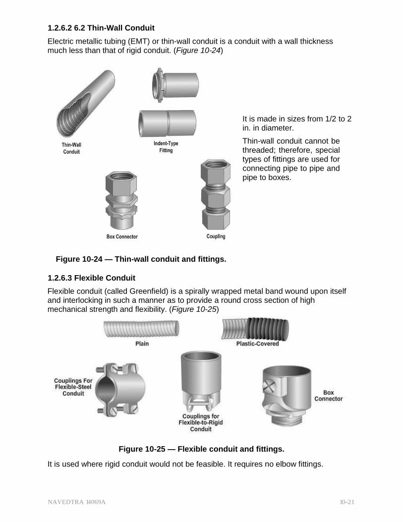
1.2.6.2 6.2 Thin-Wall Conduit
Electric metallic tubing (EMT) or thin-wall conduit is a conduit with a wall thickness much less than that of rigid conduit. (Figure 10-24)
It is made in sizes from 1/2 to 2 in. in diameter.
Thin-wall conduit cannot be threaded; therefore, special types of fittings are used for connecting pipe to pipe and pipe to boxes.
Figure 10-24 — Thin-wall conduit and fittings.
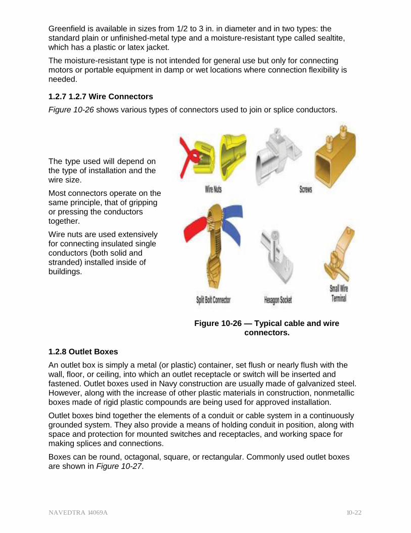
1.2.6.3 Flexible Conduit
Flexible conduit (called Greenfield) is a spirally wrapped metal band wound upon itself and interlocking in such a manner as to provide a round cross section of high mechanical strength and flexibility. (Figure 10-25)
Figure 10-25 — Flexible conduit and fittings.
It is used where rigid conduit would not be feasible. It requires no elbow fittings.
NAVEDTRA 14069A 10-22
Greenfield is available in sizes from 1/2 to 3 in. in diameter and in two types: the standard plain or unfinished-metal type and a moisture-resistant type called sealtite, which has a plastic or latex jacket.
The moisture-resistant type is not intended for general use but only for connecting motors or portable equipment in damp or wet locations where connection flexibility is needed.
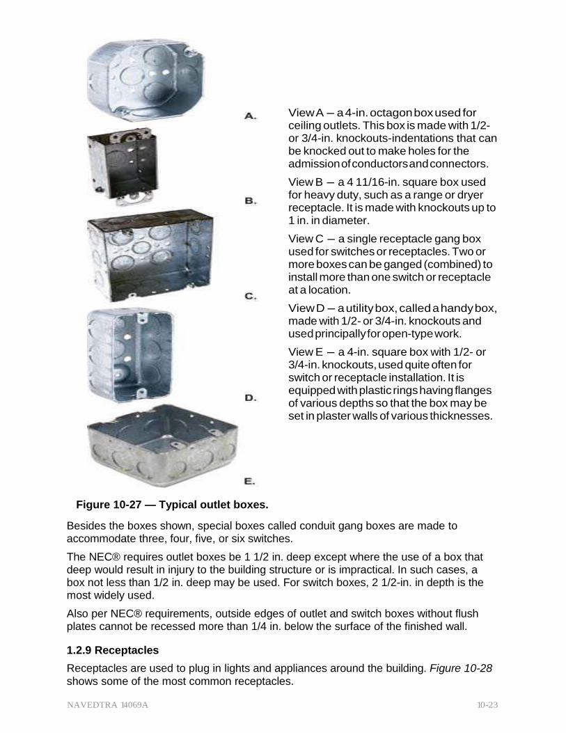
1.2.7 1.2.7 Wire Connectors
Figure 10-26 shows various types of connectors used to join or splice conductors.
The type used will depend on the type of installation and the wire size.
Most connectors operate on the same principle, that of gripping or pressing the conductors together.
Wire nuts are used extensively for connecting insulated single conductors (both solid and stranded) installed inside of buildings.
Figure 10-26 — Typical cable and wire
connectors.
1.2.8 Outlet Boxes
An outlet box is simply a metal (or plastic) container, set flush or nearly flush with the wall, floor, or ceiling, into which an outlet receptacle or switch will be inserted and fastened. Outlet boxes used in Navy construction are usually made of galvanized steel. However, along with the increase of other plastic materials in construction, nonmetallic boxes made of rigid plastic compounds are being used for approved installation.
Outlet boxes bind together the elements of a conduit or cable system in a continuously grounded system. They also provide a means of holding conduit in position, along with space and protection for mounted switches and receptacles, and working space for making splices and connections.
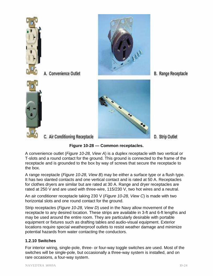
Boxes can be round, octagonal, square, or rectangular. Commonly used outlet boxes are shown in Figure 10-27.
NAVEDTRA 14069A 10-23
View A - a 4-in. octagon box used for ceiling outlets. This box is made with 1/2- or 3/4-in. knockouts-indentations that can be knocked out to make holes for the admission of conductors and connectors.
View B - a 4 11/16-in. square box used for heavy duty, such as a range or dryer receptacle. It is made with knockouts up to 1 in. in diameter.
View C - a single receptacle gang box used for switches or receptacles. Two or more boxes can be ganged (combined) to install more than one switch or receptacle at a location.
View D - a utility box, called a handy box, made with 1/2- or 3/4-in. knockouts and used principally for open-type work.
View E - a 4-in. square box with 1/2- or 3/4-in. knockouts, used quite often for switch or receptacle installation. It is equipped with plastic rings having flanges of various depths so that the box may be set in plaster walls of various thicknesses.
Figure 10-27 — Typical outlet boxes.
Besides the boxes shown, special boxes called conduit gang boxes are made to accommodate three, four, five, or six switches.
The NEC® requires outlet boxes be 1 1/2 in. deep except where the use of a box that deep would result in injury to the building structure or is impractical. In such cases, a box not less than 1/2 in. deep may be used. For switch boxes, 2 1/2-in. in depth is the most widely used.
Also per NEC® requirements, outside edges of outlet and switch boxes without flush plates cannot be recessed more than 1/4 in. below the surface of the finished wall.
1.2.9 Receptacles
Receptacles are used to plug in lights and appliances around the building. Figure 10-28 shows some of the most common receptacles.
NAVEDTRA 14069A 10-24
Figure 10-28 — Common receptacles.
A convenience outlet (Figure 10-28, View A) is a duplex receptacle with two vertical or T-slots and a round contact for the ground. This ground is connected to the frame of the receptacle and is grounded to the box by way of screws that secure the receptacle to the box.
A range receptacle (Figure 10-28, View B) may be either a surface type or a flush type. It has two slanted contacts and one vertical contact and is rated at 50 A. Receptacles for clothes dryers are similar but are rated at 30 A. Range and dryer receptacles are rated at 250 V and are used with three-wire, 115/230 V, two hot wires and a neutral.
An air conditioner receptacle taking 230 V (Figure 10-28, View C) is made with two horizontal slots and one round contact for the ground.
Strip receptacles (Figure 10-28, View D) used in the Navy allow movement of the receptacle to any desired location. These strips are available in 3-ft and 6-ft lengths and may be used around the entire room. They are particularly desirable with portable equipment or fixtures such as drafting tables and audio-visual equipment. Exterior locations require special weatherproof outlets to resist weather damage and minimize potential hazards from water contacting the conductors.
1.2.10 Switches
For interior wiring, single-pole, three- or four-way toggle switches are used. Most of the switches will be single-pole, but occasionally a three-way system is installed, and on rare occasions, a four-way system.
NAVEDTRA 14069A 10-25
A single-pole switch is a one-blade, on-and-off switch that may be installed singly or in multiples of two or more in a gang box.
In a three-way switch circuit there are two positions, either of which may be used to turn a light ON or OFF.
The typical situation is one in which one switch is at the head of a stairway and the other at the foot.
A four-way switch is an extension of a three-way circuit by the addition of a four-way switch in the line between the two three-way switches. This allows on/off switching from three locations.
Note that three- and four-way switches can be used as single-pole switches, and four- way switches can be used as three-way switches. Some activities may install all small- wattage, four-way switches for all lighting circuits to reduce their inventories.
However, three- and four-way switches are usually larger than single-pole switches and take up more box room. The size of a switch depends on its ampacity (related maximum amperage capacity). The ampacity and maximum allowable voltage are stamped on the switch.
Test Your Knowledge (Select the Correct Response)
1. Most land-based power systems use alternating current (ac) because _.
A. direct current voltage is unstable B. alternating current is cheaper to produce C. direct current requires heavier wiring D. transformers can be used only with ac
2.0.0 ELECTRICAL PLANS
Like mechanical plans, electrical plan information and layout are usually superimposed on the plot plan and the building plan, thus providing common reference points for all the respective trades.
This chapter will address electrical plans pertaining to the electrical (power) distribution system (outside power lines and equipment for multi-building installations) and the interior electrical wiring system.
With electrical drawings, the layout for both light and power is your main concern as an EA, and your tasking may include developing electrical drawings and layouts from notes, sketches, and specifications provided by the designing engineer.
You are not required to design the electrical wiring system, but you must be familiar with symbols, nomenclature, basic functions of components, and installation methods, as well as the transmission, distribution, and circuit hookups associated with the electrical systems.
In addition, you must be familiar with both NEC® and local codes, standards, and specifications, and be able to apply that knowledge in drawing electrical plans.
2.1.0 Standards and Specifications Requirements
Electrical system safety is of prime importance for both personnel and base operations. Consequently, it is imperative that all Navy electrical installations ashore conform to rigid standards and specifications. When preparing construction drawings, EAs, like

NAVEDTRA 14069A 10-26
CEs, must follow the specifications issued by Naval Facilities Engineering Command (NAVFACENGCOM).
In particular, an EA working on electrical wiring and layout diagrams for electrical plans should refer to the latest edition of American National Standards Institute (ANSI) Y32.9 and ANSI Y14.15.
2.1.1 Codes
Installing electrical systems by code requirements and procedures offers protection for the consumer against unskilled electrical labor.
In addition to providing a common standard, the NEC® serves as a basis for limiting the size and type of wiring for specific use, circuit size, outlet spacing, conduit requirements, and other functions. Be certain you always have a copy of the latest edition of the NEC® available. A copy should be maintained in the technical library.
In addition to NEC® standards, local codes are also used when separate electrical sections are applicable to the building locale.
These local codes are similar to NEC® standards for the system wiring in that all of the electrical devices and fixtures that will connect to the wiring (in the electrical plans materials list) must meet certain specifications and minimum requirements.
Underwriters Laboratories (UL) is an independent organization that tests various electrical fixtures and devices to determine if they meet minimum specification and safety requirements as set up by UL. Approved fixtures and devices may then bear UL labels. (Figure 10-29)
Figure 10-29 — Underwriters Laboratory logo.
2.1.2 Permit
On Seabee projects, utility drawings (both mechanical and electrical) receive a thorough review before the granting and issuing of an excavation (or digging) permit. This minimizes the hazards to personnel as well as underground utilities, supply lines, and structures during the construction process.
To achieve maximum safety, the reviewing agency must have accurate drawings of existing conditions. As-built and working drawings must note and reflect all minor design changes and field adjustments. Therefore, close coordination and cooperation must develop within and among all of the parties involved in the project. They jointly need to maintain periodic checks on red-lined prints so that they can compare information and verify it as up to date.
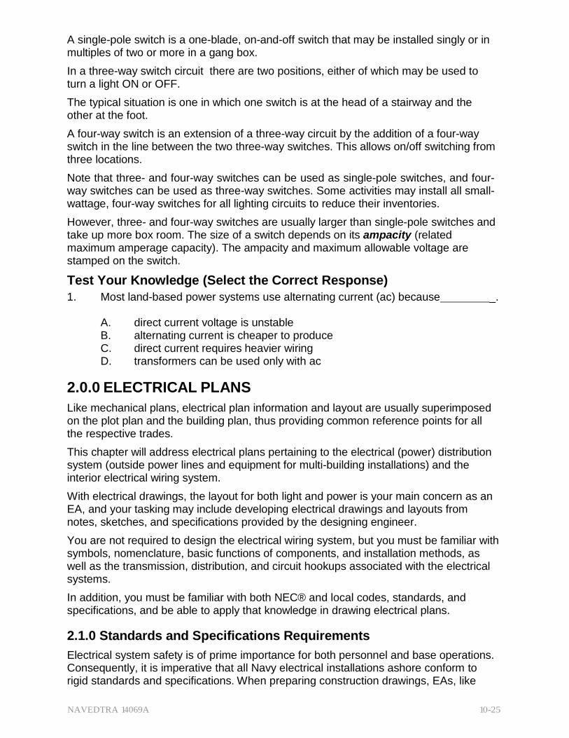
2.2.0 Electrical Symbols
There are a myriad of electrical symbols used in schematic drawings, electronics, avionics, shipboard lighting, and so on. The ones you will use as an EA will be limited to those typical of the construction industry. An electrical plan's symbols indicate general layout, units, related equipment, fixtures and fittings, and the routing and
NAVEDTRA 14069A 10-27
interconnection of various electrical wiring. Figure 10-30 shows most common types of symbols used in electrical drawings for construction.
Figure 10-30 — Common electrical symbols for construction.
To see additional or special symbols, refer to the appendix and/or to ANSI Y32.9.
To add electrical symbols on a drawing, as in drawing a mechanical plan, it is best to use templates. For example, a wiring symbol is usually drawn as a single line but it also includes slanting "tick marks" to indicate the number of wires in an electrical circuit.
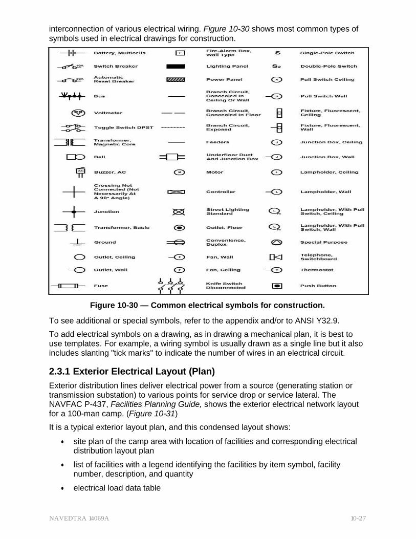
2.3.1 Exterior Electrical Layout (Plan)
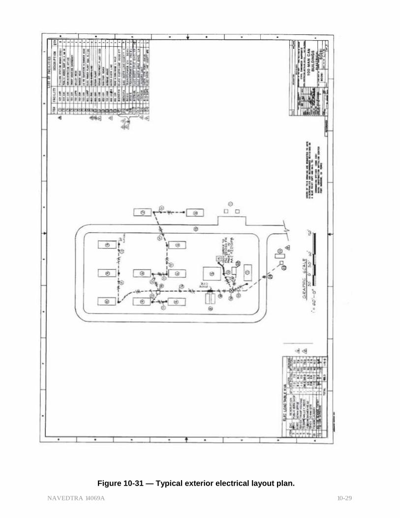
Exterior distribution lines deliver electrical power from a source (generating station or transmission substation) to various points for service drop or service lateral. The NAVFAC P-437, Facilities Planning Guide, shows the exterior electrical network layout for a 100-man camp. (Figure 10-31)
It is a typical exterior layout plan, and this condensed layout shows:
site plan of the camp area with location of facilities and corresponding electrical distribution layout plan
list of facilities with a legend identifying the facilities by item symbol, facility number, description, and quantity
electrical load data table

NAVEDTRA 14069A 10-28
As an EA, you may be called upon to trace, modify, revise, and even review the workability of this or similar drawings. Therefore, you need to study and become comfortably familiar with electrical plans while gaining a working knowledge of how the Advanced Base Functional Component (ABFC) System works. Review the contents of the NAVFAC P-437. It offers a wide variety of plans, drawings, and applications for use in Seabee construction.
NAVEDTRA 14069A 10-29
Figure 10-31 — Typical exterior electrical layout plan.
NAVEDTRA 14069A 10-30
2.4.1 Interior Electrical Layout (Plan)
The interior electrical layout for a small building is usually drawn into a print of the floor plan. On larger projects, additional separate drawing sheets are necessary to accommodate detailed information needed to meet construction requirements.
Figure 10-32 shows an interior electrical layout of a typical public works shop. Note again that the electrical wiring diagram is superimposed on an architectural floor plan (Lighting circuits use three-wire No. 12 AWG).
The drawing also provides additional specifics needed build this PW shop: a list of assemblies, an electrical load table, and a panel schedule for the 225-A three-phase circuit breaker. The service lateral entrance (item 10 on the list of assemblies) delivers a four-wire, 120/208-V power into the building.
Follow these basic steps as a guide in developing an interior electrical plan.
Show:
1. location of service panel and its rating in amps
2. all wall and ceiling outlets
3. all special-purpose outlets such as telephones, communications, doorbells, and so forth
4. all switches and their outlet connections
5. all convenience outlets
If required, complete a schedule of electrical fixtures, with symbols, legends, and notes necessary to clarify any special requirements in the drawing that are not stipulated in the specifications. Following these sequential steps will establish good working habits to minimize omissions or errors in your drawings.

NAVEDTRA 14069A 10-31
3
.:; •. i
:: .. ..w•
1
9
9 e ?
t
·.•
I
H
I
I I
"•"'i i :;
, N
,
.w ;;;
•v" >_,
f'ja
: ";i'
."".,.''
y er ..: I I I I I I I I
9 9 =9 111==
1 I I I
I k,I '©
t • ,,, 1
c;::( · - _ _ -<...I}_ _l_<l.I _ _ I Nll1
0 -:.1 J, -:.1
9 I I I I I ,,. t I I -...I I I
0 0 0 6 '
"'
!!E • i ;
j f
I
</ :; I I
i@ I I / I I
I
' ? 9 I
I I I I
I \ I \
? 9 I I I I
9 9 •
I t J, I • 1 I
'o
·.'..
_,
I t
:e 2 . ;
? 9 I t I
•N1
9 9 I I I I t I
6 0
9 9 t t I
-N:".1'
9 ? '
I I I I I I
6 0
Figure 10-32 -Typical interior electrical plan.
NAVEDTRA 14069A 10-32
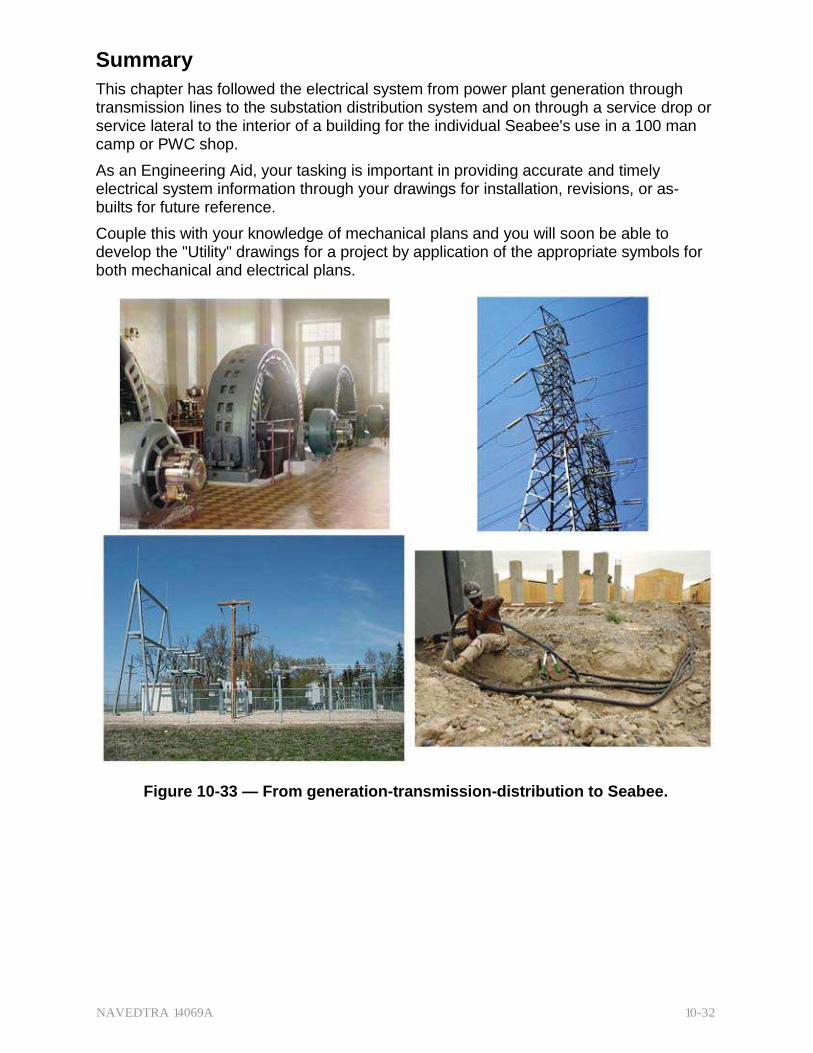
Summary
This chapter has followed the electrical system from power plant generation through transmission lines to the substation distribution system and on through a service drop or service lateral to the interior of a building for the individual Seabee's use in a 100 man camp or PWC shop.
As an Engineering Aid, your tasking is important in providing accurate and timely electrical system information through your drawings for installation, revisions, or as- builts for future reference.
Couple this with your knowledge of mechanical plans and you will soon be able to develop the "Utility" drawings for a project by application of the appropriate symbols for both mechanical and electrical plans.
Figure 10-33 — From generation-transmission-distribution to Seabee.

NAVEDTRA 14069A 10-33
Review Questions (Select the Correct Response) 1. Which of the following descriptions best defines electrical distribution?
A. An electrical transmission system that carries electrical current
externally from the generating station via substations and transformers to building locations.
B. A power plant that distributes electrical energy by conversion from some other energy source such as wind, geothermal, coal, etc.
C. An internal electrical wiring system that distributes electricity to illuminate the building and provide power to appliances and equipment.
D. A transmission tower that distributes electrical energy from a substation to a building without a transformer.
2. A complete electrical delivery network is considered a combination of the
section and the section.
A. generation, transmission B. transmission, distribution C. transmission, internal wiring D. distribution, internal wiring
3. What type of feeder lines do Seabees use at most advance bases?
A. Underground cable B. Automatic C. Overhead D. Internal
4. Alternators for a three-wire distribution system are connected in a
configuration.
A. secondary B. primary C. wye (Y) D. delta
5. A delta connected alternator system has voltage rating(s).
A. 1
B. 2
C. 3
D. 4
6. A wye (Y) connected alternator system has voltage rating(s).
A 1
B. 2
C. 3
D. 4

NAVEDTRA 14069A 10-34
7. What element in a three-wire power distribution system makes it possible to draw 110V from a 220V alternating generator?
A. Transformer B. Ground Wire C. Neutral Wire D. Bridge
8. What element in a four-wire power distribution system makes it possible to
draw 110V from a 220V alternating generator?
A. Transformer B. Ground Wire C. Neutral Wire D. Bridge
9. What type of voltage is required for long-distance transmission?
A. Exact voltage from power plant generator B. Voltage higher than normally generated C. Voltage lower than normally generated D. Voltage can be flexible depending on delta or wye (Y) connection
10. What type of transformer is placed between the transmission line and
service distribution?
A. 220V B. 110V C. Step-up D. Step-down
11. According to Ohm's law, current varies to .
A. directly, resistance B. inversely, voltage C. inversely, resistance D. It does not vary
12. Which of the following reasons is NOT an advantage of installing electrical
distribution systems underground, rather than overhead?
A. Underground installation costs are less. B. Underground lines are secure against high winds. C. Underground lines are less susceptible to enemy attack. D. Underground installation provides open land areas free from
distribution systems.

NAVEDTRA 14069A 10-35
13. Which underground power distribution system do Seabees most frequently install?
A. Conduits located in tunnels B. Duct lines C. Cables buried directly D. Tunneled
14. What supplies power from the exterior distribution system to the entry
point of the building?
A. Panel board B. Switchboard C. Service drop or lateral D. Service entrance
15. What term is used for the starting point for interior wiring?
A. Service equipment B. Service conductor C. Service entrance D. Service lateral
16. What amperage does the NEC® recommend for circuit breaker type
entrance switches?
A. 50A B. 60A C. 100A D. 110A
17. What amperage does the NEC® recommend for individual residences?
A. 50A B. 60A C. 100A D. 110A
18. Lighting panels are normally equipped with automatic circuit
breakers.
A. 15A single pole B. 20A single pole C. 30A paired D. 50A paired

NAVEDTRA 14069A 10-36
19. Compared to a No. 4 AWG conductor, the size of a No. 16 AWG conductor is .
A. smaller B. shorter C. larger D. longer
20. What wire size is most frequently used for interior wiring?
A. 8 AWG B. 12 AWG C. 16 AWG D. 18 AWG
21. What is another term for multi-wire conductors?
A. Pairs B. Doubles C. Triples with ground D. Cable
22. In which of the following locations is ROMEX NOT authorized for use?
A. Embedded in concrete B. Garages C. Storage battery rooms D. All of the above
23. Which of the following types of insulated wire should be used for
installation in wet locations?
A. RH B. RHW C. RUH D. All of the above
24. A manual conduit bender is called a _.
A. turning tool B. curving tool C. hickey D. turn out
25. Instead of manually making a sharp bend in rigid aluminum conduit, which
of the following fittings should you use?
A. Coupling B. Conduit union C. Galvanized steel elbow D. Condulet

NAVEDTRA 14069A 10-37
26. Which type of PVC conduit is designated for direct earth burial?
A. Type I B. Type I R C. Type II D. Type II R
27. Thin-wall conduit .
A. must be threaded B. uses a solvent type adhesive weld C. can use rigid conduit fittings D. uses special types of fittings
28. Which of the following boxes would you normally use for a ceiling outlet?
A. 4 11/16-in. square heavy duty B. Utility C. 4-in. octagon D. 4-in. square
29. According to NEC® requirements, what is the maximum recess allowed
below a finished wall for switch boxes?
A. 1/16-inch B. 1/8-inch C. 1/4-inch D. 1/2-inch
30. (True or False) If you use the National Electrical Code, NEC®, you do not
need to follow local codes.
A. True B. False
31. Utility drawings (both mechanical and electrical) are thoroughly reviewed
before granting and issuing permits.
A. building B. construction C. excavation D. demolition
NAVEDTRA 14069A 10-38
32. Which of the following definitions best describes the symbol for a special- purpose receptacle outlet?
A. A circle inscribed in a triangle B. A circle containing a smaller inscribed circle C. A triangle D. A solid triangle inscribed in a circle
33. Which of the following definitions best describes the symbol for a single-
pole switch?
A. An S B. A circle containing an inscribed S C. A square containing an inscribed S D. A vertically oriented rectangle with a horizontal line on the left
34. Which of the following definitions best describes the symbol for a ceiling
outlet?
A. A circle B. A circle containing an inscribed C C. A circle with four radiating lines in an X pattern D. A circle containing an inscribed L
35. What NAVFAC publication offers a wide variety of plans, drawings, and
applications for use in Seabee Advanced Base Functional Component (ABFC) systems?
A. NAVFAC P-307 B. NAVFAC P-405 C. NAVFAC P-437 D. NAVFAC P-300
36. (True or False) When drawing exterior or interior electrical plans, you
should not superimpose them over site or building plans.
A. True B. False
NAVEDTRA 14069A 10-39
Trade Terms Introduced in this Chapter
Alternator An electric generator that produces alternating current. The generator's coil is rotated (by a turbine, motor, or other power source), and its circular path causes it to cut cross a magnetic field (set up by strong magnets), first in one direction, then the other, with each cycle.
Ampacity The current rating or current-carrying capacity which a device can continuously carry while remaining within its temperature rating.
Buses An electrical bus (sometimes spelled buss) is a physical electrical interface where many devices share the same electric connection. This allows signals to be transferred between devices (allowing information or power to be shared). A bus often takes the form of an array of wires that terminate at a connector that allows a device to be plugged into the bus.
Ductile Easily drawn into wire or hammered thin.
National Electrical Code (NEC®)
A United States standard for the safe installation of electrical wiring and equipment. It is part of the National Fire Codes series published by the National Fire Protection Association (NFPA).
Ohm’s Law Applied to electrical circuits; it states that the current through a conductor between two points is directly proportional to the potential difference or voltage across the two points, and inversely proportional to the resistance between them.

NAVEDTRA 14069A 10-40
Additional Resources and References
This chapter is intended to present thorough resources for task training. The following reference works are suggested for further study. This is optional material for continued education rather than for task training.
Blueprint Reading and Sketching, NAVEDTRA 14040, Naval Education and Training Program Management Support Activity, Pensacola, FL, 2003.
Dagostino, F. R., Mechanical and Electrical Systems in Construction and Architecture, Reston Publishing Company, Inc., Reston, VA 1978.
Facilities Planning Guide, NAVFAC P-437, Naval Facilities Engineering Command, Alexandria, Va., 1988.
Graphic Symbols for Electric Wiring and Layout Diagrams Used in Architectural and Building Construction, ANSI Y32.9, The Institute of Electrical and Electronics Engineers, NY, 1972.
U.S. Department of Defense, Construction Drafting, TM 5-581-B, Headquarters, Department of the Army, Washington, D.C., 1972.

NAVEDTRA 14069A 10-41
CSFE Nonresident Training Course – User Update
CSFE makes every effort to keep their manuals up-to-date and free of technical errors. We appreciate your help in this process. If you have an idea for improving this manual, or if you find an error, a typographical mistake, or an inaccuracy in CSFE manuals, please write or email us, using this form or a photocopy. Be sure to include the exact chapter number, topic, detailed description, and correction, if applicable. Your input will be brought to the attention of the Technical Review Committee. Thank you for your assistance.
Write: CSFE N7A 3502 Goodspeed St. Port Hueneme, CA 93130
FAX: 805/982-5508
E- mail: [email protected]
Rate_ Course Name
Revision Date Chapter Number Page Number(s)
Description
(Optional) Correction
(Optional) Your Name and Address

NAVEDTRA 14069A 11-1
Chapter 11
Construction Drawings
Topics
1.0.0 Types of Construction Drawings
2.0.0 Project Drawing Preparation
3.0.0 Main Divisions of Project Drawing
To hear audio, click on the box.
Overview
Whenever a property's cognizant authority intends to change the property by disturbing the natural soil or erecting a structure, they need to communicate their intentions to the constructors. They do this through a set of construction drawings.
The drawings describe the soil disturbance, structure, or facility with a set of related drawings that give a sequential graphic description of each phase of the construction process. For example, site drawings will show the location, boundaries, contours, and outstanding physical features of the construction project's footprint and its adjoining areas.
Depending on the size and complexity of the project, succeeding drawings will provide further graphic and printed instructions for each phase of construction. They may include architectural for concept and finishes, structural for foundation and superstructure, mechanical for water distribution and waste removal, and electrical for power distribution. Others may include, although less frequently, heating, ventilating, and air-conditioning, fire sprinkler systems, alarm systems, and/or landscaping.
This chapter will cover the typical drawings used by most moderate sized construction projects. There may be more (or fewer) drawings for any given project, but the concept is the same for all drawings: convey the designer's concept and intentions through drawings to the builder. As an EA, one of your tasks will be to provide accurate information through your drawings for your unit's Seabees to get the job done.
Objectives
When you have completed this chapter, you will be able to do the following.
1. Describe the different types of construction drawings.
2. Describe the procedures for preparation of project drawings.
3. State the main divisions of project drawings.
Prerequisites
None
NAVEDTRA 14069A 11-2
This course map shows all of the chapters in Engineering Aid Basic. The suggested training order begins at the bottom and proceeds up. Skill levels increase as you advance on the course map.
Topographic Surveying and Mapping
E
Indirect Leveling/Level and Traverse Computations N
G Care and Adjustment of Survey Equipment
I
Materials Testing: Soil and Concrete N
Direct Leveling and Basic Engineering Surveys E
Horizontal Control E
Direct Linear Measurements and Field Survey Safety R
I Surveying: Elements and Equipment
N Construction Drawings
G
Electrical: Systems and Plans
Mechanical: Systems and Plans AID
Concrete and Masonry
B
Wood and Light Frame Structures A
Drafting: Projections and Sketching S
Drafting: Geometric Construction I
Drafting: Fundamentals and Techniques C
Drafting: Equipment
Mathematics and Units of Measurement
Engineering Aid Rating
Features of this Manual
This manual has several features which make it easy to use online.
Figure and table numbers in the text are italicized. The figure or table is either next to or below the text that refers to it.
The first time a glossary term appears in the text, it is bold and italicized. When your cursor crosses over that word or phrase, a popup box displays with the appropriate definition.
Audio and video clips are included in the text, with an italicized instruction telling you where to click to activate it.
Review questions that apply to a section are listed under the Test Your Knowledge banner at the end of the section. Select the answer you choose. If the

NAVEDTRA 14069A 11-3
answer is correct, you will be taken to the next section heading. If the answer is incorrect, you will be taken to the area in the chapter where the information is for review. When you have completed your review, select anywhere in that area to return to the review question. Try to answer the question again.
Review questions are included at the end of this chapter. Select the answer you choose. If the answer is correct, you will be taken to the next question. If the answer is incorrect, you will be taken to the area in the chapter where the information is for review. When you have completed your review, select anywhere in that area to return to the review question. Try to answer the question again.

NAVEDTRA 14069A 11-4
1.0.0 TYPES OF CONSTRUCTION DRAWINGS
Construction drawings are categorized by intended purpose. Besides the type used in the field to do the on-site activities, other types are often needed in the larger scope of "Construction" from conceptual ideas to the finite details of a manufactured part. This chapter will cover some of the types commonly used in military construction.
1.1.0 Presentation Drawings
Presentation drawings (as the name implies) present the proposed building or facility in an attractive setting in its natural surrounding at the proposed site. They often consist of perspective views complete with colors and shading. (Figure 11-1) Presentation drawings are usually used to "sell" an idea or design concept, so as an EA assigned to the drafting section, you would rarely be tasked with developing them, but you need to be able to recognize them.
Figure 11-1 – Example of presentation drawing-Gulfport duplexes post Katrina.
1.2.0 Shop Drawings
Shop drawings can be more than just a drawing. They can also be schedules, diagrams, or other related data intended to illustrate materials, products, or systems for some portion of the work. (Figure 11-2) The construction contractor, subcontractor, manufacturer, distributor, or supplier can prepare them along with providing product data. Product data include brochures, illustrations, performance charts, and other

NAVEDTRA 14069A 11-5
information by which the work will be judged. As an EA, you may be required to draft shop drawings for minor shop and field projects.
Figure 11-2 – Typical shop drawing — (Doorframe ordering options.)
You may need to draw shop items, such as doors, cabinets, and small portable structures from portions of the design drawings, specifications, material schedules, or from freehand sketches given by the design engineer.
1.3.1 Master Plan Drawings
Master plan drawings are commonly used in the architectural, topographical, and construction planning processes. They show sufficient features for use as guides in long-range area development. (Figure 11-3)
Figure 11-3 – Example of simple existing plan and proposed master plan.
NAVEDTRA 14069A 11-6
They usually contain:
North point indicator (arrow)
Section boundary lines
Horizontal and vertical control data
Contour lines
Acreage
Streams
Profiles
Existing utilities
Rights-of-way and appurtenances
Locations and descriptions of existing and proposed structures
Existing and proposed surfaced and unsurfaced roads and sidewalks
On existing and proposed Navy installations, the Resident Officer in Charge of Construction (ROICC) and the Public Works Center (PWC) constantly maintain and upgrade the master plan and general development drawings as well as the as-builts.
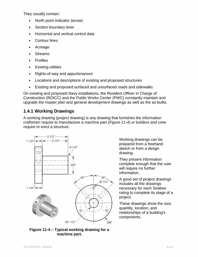
1.4.1 Working Drawings
A working drawing (project drawing) is any drawing that furnishes the information craftsmen require to manufacture a machine part (Figure 11-4) or builders and crew require to erect a structure.
Working drawings can be prepared from a freehand sketch or from a design drawing.
They present information complete enough that the user will require no further information.
A good set of project drawings includes all the drawings necessary for each Seabee rating to complete its stage of a project.
These drawings show the size, quantity, location, and relationships of a building's components.
Figure 11-4 – Typical working drawing for a machine part.
NAVEDTRA 14069A 11-7
A complete set of project drawings consists of general drawings, detail drawings, assembly drawings, and always a bill of materials.
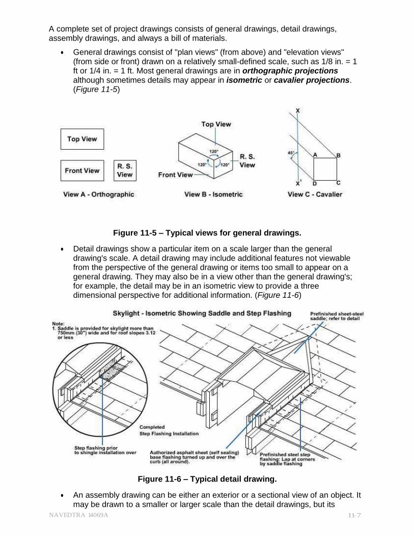
General drawings consist of "plan views" (from above) and "elevation views" (from side or front) drawn on a relatively small-defined scale, such as 1/8 in. = 1 ft or 1/4 in. = 1 ft. Most general drawings are in orthographic projections although sometimes details may appear in isometric or cavalier projections. (Figure 11-5)
Figure 11-5 – Typical views for general drawings.
Detail drawings show a particular item on a scale larger than the general drawing's scale. A detail drawing may include additional features not viewable from the perspective of the general drawing or items too small to appear on a general drawing. They may also be in a view other than the general drawing's; for example, the detail may be in an isometric view to provide a three dimensional perspective for additional information. (Figure 11-6)
Figure 11-6 – Typical detail drawing.
An assembly drawing can be either an exterior or a sectional view of an object. It may be drawn to a smaller or larger scale than the detail drawings, but its
NAVEDTRA 14069A 11-8
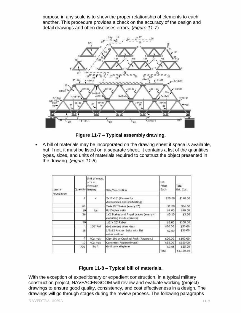
purpose in any scale is to show the proper relationship of elements to each another. This procedure provides a check on the accuracy of the design and detail drawings and often discloses errors. (Figure 11-7)
Figure 11-7 – Typical assembly drawing.
A bill of materials may be incorporated on the drawing sheet if space is available, but if not, it must be listed on a separate sheet. It contains a list of the quantities, types, sizes, and units of materials required to construct the object presented in the drawing. (Figure 11-8)
Figure 11-8 – Typical bill of materials.
With the exception of expeditionary or expedient construction, in a typical military construction project, NAVFACENGCOM will review and evaluate working (project) drawings to ensure good quality, consistency, and cost effectiveness in a design. The drawings will go through stages during the review process. The following paragraphs

NAVEDTRA 14069A 11-9
describe these stages, from the initial development of the project to the final phase of construction.
1.4.1 Preliminary Drawings
The designer or architects and engineers (A/E) firm prepares preliminary drawings in the early planning or promotional stage of a project's development. They are strictly initial concepts and provide a means of communication between the designer and the customer. Preliminary drawings are NOT intended for construction. Their purpose is to explore design concepts, material selection, and preliminary cost estimates; solicit input and approval by the customer; and provide a basis for preparing working drawings.
By the time preliminary drawings reach the 35-percent stage of completion, they will contain the following information at a minimum:
Site plans
Architectural floor plans
Elevations
Building sections
Preliminary finish schedule and furniture layout
Interior and exterior mechanical and electrical data
Civil and structural details
If the preliminary drawings are intended for use as Seabee project, the senior regional Seabee command will review them for construction methods or procedures. If the project is to be contracted to other sources, the local ROICC will provide the review.
1.4.2 Drawings
100% complete and used for bidding, the final drawings (Finals) are signed by the contracting officer and become the official contract drawings once the contract is awarded. However, with the concurrence of both the contractor and contracting officer, final drawings are often revised to show adjustments made by a scope change or a change order.
At this stage, no further functional input may be introduced into the final drawings because of time constraints or cost implications. In general, final drawings, together with project specifications, cost estimates, and all of the calculations, comprise the final stages of design requirements.
1.4.3 awings
Red-lined drawings get their name from the color used to indicate a minor design change or field adjustment. Using the official contract drawings, the mark-ups usually come from the field by the various trades involved in the project with the mark-ups reflecting the as-built conditions during construction.
1.4.4 As-Built Drawings
These are the original contract drawings (or copies) that are changed to incorporate the various as-built conditions from all the accumulated red-lined drawings. The construction contractor or military construction force (NMCB) must provide the ROICC with as-built drawings indicating any deviations from the contract drawings. The as-built marked-up prints must reflect exact as-built conditions and show all features of the

NAVEDTRA 14069A 11-10
project as constructed. After completion of the project, the ROICC transmits the as-built marked-up prints to their cognizant Engineering Field Division (EFD).
1.4.5 Record Drawings
Record drawings are the original contract drawings (corrected according to the marked prints) that provide a permanent record of as-built conditions upon completion of a project. EFD may retain custody or transfer them to stations with a Public Works Center (PWC).
1.5.0 Conceptual Designs
Conceptual designs in the Navy include both definitive designs and standard designs for structures and facilities needed on a repetitive basis. Both are prepared designs or drawings defining various functional, engineering, and logistical requirements. They provide a uniform basis for planning and design.
1.5.1 Definitive Designs
Definitive designs are drawings of typical buildings and structures found in NAVFAC P- 272, Definitive Designs for Naval Shore Facilities, Part 1. They provide general guidance to prepare project drawings and specifications. A/E contractors or in-house staff can refer to these definitive designs for floor plan arrangements, building sections and elevations, and utility requirements.
NAVFACP-272 Part 2 contains specific guidance in preparing project designs for more complex facilities. These may include equipment layouts, piping diagrams, electrical schematics, and other critical requirements.
NOTE
Valid technical information from P-272 has been included in the Unified Facilities Criteria (UFC) for the particular facility type; see the appropriate UFC for further information.
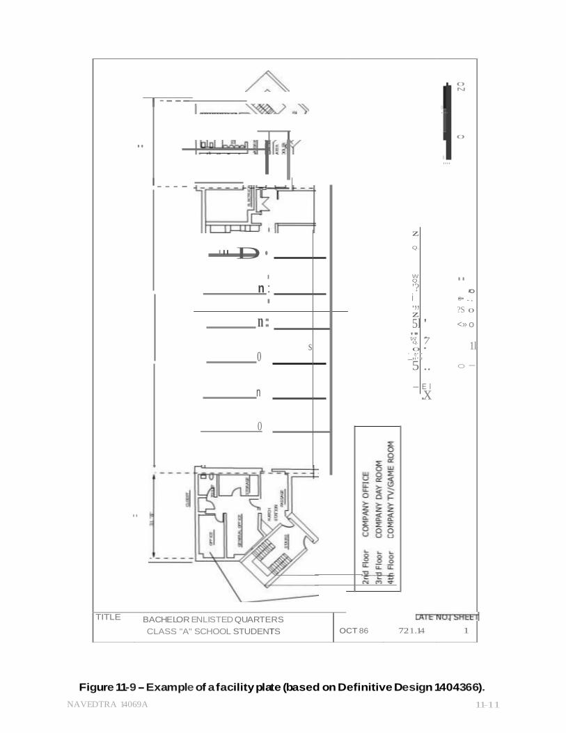
The facilities type of design includes additional information in the form of single-line schematics, bubble diagrams, or facility plates (Figure 11-9), graphics that show functional relationships or building layout such as individual rooms within the facility.
Facility plates may show:
The location of equipment and furnishings within a room
The location of utilities serving the room
The location and size of doors and windows
A ceiling plan reflecting the location of lighting fixtures
Other technical design information about the room
Facility plates are used instead of definitive designs whenever the plates effectively convey the necessary design data, or whenever the definitive designs are scheduled for development, revision, or validation. Most of the facility plates can be found within the pages of criteria or design manuals (DMs).
NAVEDTRA 14069A 11-11
- - - -
..
- - - -
I II D •
I
n : I
n::
0
n
0
..
z
Q.
w Q.
'? i.,, z
5l ' "W' '
0 ' "_,Q;::); 5 ..
-
.E
xl
0 N
0....
0
0....
..
.0. .'.°, ?S 0
<» o
o -
TITLE BACHELOR ENLISTED QUARTERS
CLASS "A" SCHOOL STUDENTS
OCT 86
72 1.14
1
s Q. 7
1l
Figure 11-9 - Example of a facility plate (based on Definitive Design 1404366).

NAVEDTRA 14069A 11-12
1.5.2 Standard Designs
Standard designs are detailed working drawings of specialized, unique, naval facility structures, such as waterfronts and fleet moorings, aircraft operations and maintenance facilities, and ammunition storage facilities.
They form a part of the construction documents and require only supplemental drawings for adapting the facility to the specific site. These drawings (except for ammunition facilities) can be modified as necessary to meet on-site requirements.
WARNING
Ammunition and explosive design standards may NOT be modified without approval from Naval Facilities Engineering Command (NAVFACENGCOM).
WARNING
When using standard designs for a construction project, with or without modifications, the cognizant EFD must assign new title blocks and drawing numbers.
A third source of detailed construction drawings, although NOT definitive, is the NAVFAC P-437, Facilities Planning Guide, Vol. 1. The P-437 contains facility and assembly drawings of pre-engineered structures used to meet the Naval Construction Force (NCF) needs at advanced bases in peacetime and during contingency operations. Thus, if construction planners need a particular facility to meet tactical and/or strategic situational requirements, they can easily and readily identify the required facility and provide support.
Along with the detailed drawings, the P-437 also provides other useful information for Seabee planners such as the required land area, crew size and man-hours by skill, and the fuel necessary to make a component, facility, or assembly operational.
As an EA, you should realize the importance of becoming familiar with the contents of NAVFAC P-437.
Test your Knowledge (Select the Correct Response)
1. An EA assigned to the drafting section would rarely be tasked with developing a drawing.
A. shop B. preliminary C. working D. presentation
2.0.0 PROJECT DRAWING PREPARATION
All NAVFACENGCOM project drawings are prepared according to ASME Y14.100. Military handbook UFC 1-300-09N provides policy and procedure for preparing and developing project drawings.
They must be complete, accurate, and explicit. For naval facility construction projects, the project drawings and the design specifications are the basis for both contract and construction. EAs and in-house planners also benefit from clear and consistent project drawings resulting from the policies and procedures in UFC 1-300-09N, especially when revising project drawings.

NAVEDTRA 14069A 11-13
2.1.0 Policy and Standards
NAVFACENGCOM establishes the design criteria for project drawings. These criteria also apply to the definitive designs, standard designs, standard drawings, and project specifications. NAVFACENGCOM allows EFDs and A/Es latitude in new concepts, creative thinking, and the use of new materials, but when they are considering deviations from mandatory criteria, they need to obtain prior clearance from NAVFACENGCOM headquarters.
Use customary U.S. dimensions on project drawings unless the project is in an area that normally uses System International (SI).The International System of Units is the internationally accepted "metric" system. However, use of the word "metric" is no longer an accepted practice. For details of the proper use of SI units, refer to IEEE/ASTM SI 10-1997, Standard for Use of International System of Units (SI): The Modern Metric System for generic conversions, and ASTM E621-79, Recommended Practice for the Use of Metric (SI) Units in Building Design and Construction, for conversions in engineering and design.
2.2.1 Order of Drawings
Arrangement of project drawings for buildings and structures follow a specific order:
1. Title Sheet and Index - specific project title and an index of drawings (for projects containing 60 or more drawings)
2. Plot or Vicinity Plans - plot or vicinity plans or both, as well as civil and utility service plans (for small projects, this sheet should include an index of drawings)
3. Landscape and Irrigation - (if applicable)
4. Architectural - (including interior design as applicable)
5. Structural
6. Mechanical - (heating, ventilation, and air conditioning)
7. Plumbing - (water service and waste removal)
8. Electrical - (interior service from utility service plan)
9. Fire Protection - (fireproofing and suppression)
For NAVFACENGCOM drawings, use the following drawing sheet sizes and format.
Flat 17 x 22 (C size) - When small sheets are required
Flat 22 x 34 (D size) - for project and other drawings
Flat 28 x 40 (F size) - option to 22 x 34
For further information about drawing sizes and format, refer to chapter 4. 2.2.1 Title Blocks
The title block provides significant information about both the approval process and the development of the drawing. (Figure 11-10) It includes:
Name and location of the activity preparing the drawing
Drawing title and number
Approval within the activity
Approval by an activity other or different than the source preparing the drawing
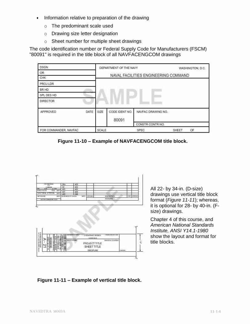
NAVEDTRA 14069A 11-14
Information relative to preparation of the drawing
o The predominant scale used
o Drawing size letter designation
o Sheet number for multiple sheet drawings
The code identification number or Federal Supply Code for Manufacturers (FSCM) "80091" is required in the title block of all NAVFACENGCOM drawings
Figure 11-10 – Example of NAVFACENGCOM title block.
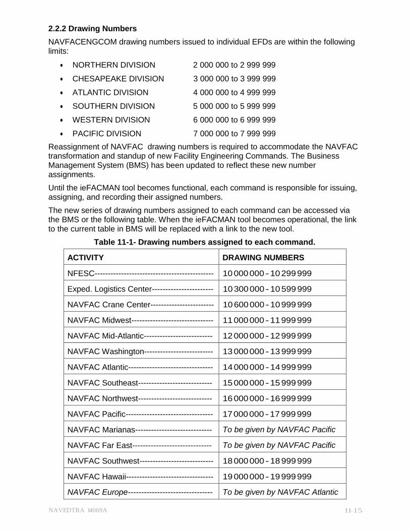
All 22- by 34-in. (D-size) drawings use vertical title block format (Figure 11-11); whereas, it is optional for 28- by 40-in. (F- size) drawings.
Chapter 4 of this course, and American National Standards Institute, ANSI Y14.1-1980 show the layout and format for title blocks.
Figure 11-11 – Example of vertical title block.
NAVEDTRA 14069A 11-15
2.2.2 Drawing Numbers
NAVFACENGCOM drawing numbers issued to individual EFDs are within the following limits:
NORTHERN DIVISION 2 000 000 to 2 999 999
CHESAPEAKE DIVISION 3 000 000 to 3 999 999
ATLANTIC DIVISION 4 000 000 to 4 999 999
SOUTHERN DIVISION 5 000 000 to 5 999 999
WESTERN DIVISION 6 000 000 to 6 999 999
PACIFIC DIVISION 7 000 000 to 7 999 999
Reassignment of NAVFAC drawing numbers is required to accommodate the NAVFAC transformation and standup of new Facility Engineering Commands. The Business Management System (BMS) has been updated to reflect these new number assignments.
Until the ieFACMAN tool becomes functional, each command is responsible for issuing, assigning, and recording their assigned numbers.
The new series of drawing numbers assigned to each command can be accessed via the BMS or the following table. When the ieFACMAN tool becomes operational, the link to the current table in BMS will be replaced with a link to the new tool.
Table 11-1- Drawing numbers assigned to each command.
ACTIVITY DRAWING NUMBERS
NFESC--------------------------------------------- 10 000 000 - 10 299 999
Exped. Logistics Center----------------------- 10 300 000 - 10 599 999
NAVFAC Crane Center------------------------ 10 600 000 - 10 999 999
NAVFAC Midwest------------------------------- 11 000 000 - 11 999 999
NAVFAC Mid-Atlantic-------------------------- 12 000 000 - 12 999 999
NAVFAC Washington-------------------------- 13 000 000 - 13 999 999
NAVFAC Atlantic-------------------------------- 14 000 000 - 14 999 999
NAVFAC Southeast---------------------------- 15 000 000 - 15 999 999
NAVFAC Northwest---------------------------- 16 000 000 - 16 999 999
NAVFAC Pacific--------------------------------- 17 000 000 - 17 999 999
NAVFAC Marianas----------------------------- To be given by NAVFAC Pacific
NAVFAC Far East------------------------------ To be given by NAVFAC Pacific
NAVFAC Southwest---------------------------- 18 000 000 - 18 999 999
NAVFAC Hawaii--------------------------------- 19 000 000 - 19 999 999
NAVFAC Europe-------------------------------- To be given by NAVFAC Atlantic
NAVEDTRA 14069A 11-16
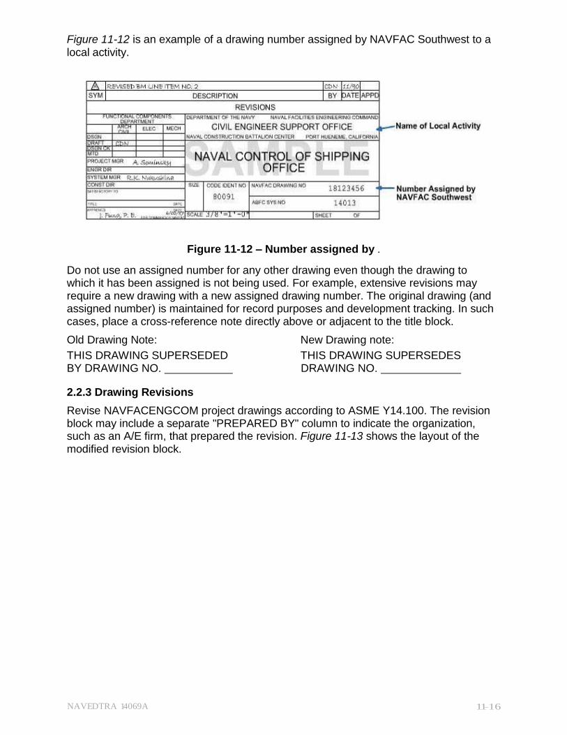
Figure 11-12 is an example of a drawing number assigned by NAVFAC Southwest to a local activity.
Figure 11-12 – Number assigned by .
Do not use an assigned number for any other drawing even though the drawing to which it has been assigned is not being used. For example, extensive revisions may require a new drawing with a new assigned drawing number. The original drawing (and assigned number) is maintained for record purposes and development tracking. In such cases, place a cross-reference note directly above or adjacent to the title block.
Old Drawing Note: New Drawing note:
THIS DRAWING SUPERSEDED THIS DRAWING SUPERSEDES BY DRAWING NO. DRAWING NO.
2.2.3 Drawing Revisions
Revise NAVFACENGCOM project drawings according to ASME Y14.100. The revision block may include a separate "PREPARED BY" column to indicate the organization, such as an A/E firm, that prepared the revision. Figure 11-13 shows the layout of the modified revision block.
NAVEDTRA 14069A 11-17
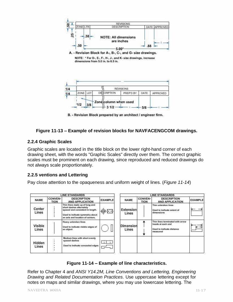
Figure 11-13 – Example of revision blocks for NAVFACENGCOM drawings.
2.2.4 Graphic Scales
Graphic scales are located in the title block on the lower right-hand corner of each drawing sheet, with the words "Graphic Scales" directly over them. The correct graphic scales must be prominent on each drawing, since reproduced and reduced drawings do not always scale proportionately.
2.2.5 ventions and Lettering
Pay close attention to the opaqueness and uniform weight of lines. (Figure 11-14)
Figure 11-14 – Example of line characteristics.
Refer to Chapter 4 and ANSI Y14.2M, Line Conventions and Lettering, Engineering Drawing and Related Documentation Practices. Use uppercase lettering except for notes on maps and similar drawings, where you may use lowercase lettering. The
NAVEDTRA 14069A 11-18
minimum allowable height of freehand letters is 5/32 (0.156) in. and of mechanical or computer graphics is 0.150 in. For abbreviations on drawings, use MIL-STD-12D.
2.3.1 Dimensioning and Tolerancing
Clearly define engineering intent by preparing all dimensions and tolerances according to ANSI Y14.5M, Dimensioning and Tolerancing for Engineering Drawings. Some of the fundamental rules are as follows:
1. A toleranced dimension may:
o Have it applied directly to the dimension
o Be indicated by a general note on the drawing sheet
2. Dimensions:
o Should be arranged to provide optimum readability of required information
o Should be selected to suit the function
o Should not be subject to more than one interpretation
3. Dimensioning for size, form, and location of features are:
o To be complete
o To provide no more dimensions than those necessary for complete definition
o Not to use "sealing" (measuring the size of a feature directly from an engineering drawing)
o Not to use assumptions of a distance or size
o To minimize the use of a reference dimension
Dimensioning format and standards to meet specific requirements will be discussed in this chapter. Notice that dimensioning construction or project drawings differs in some applications from dimensioning general technical drawings. This occurs primarily because of the materials and methods of construction.
2.3.1 Units of Measure
A drawing's units of measurement should meet the criteria of the user and the geographical area in which the plans will be used. The U.S. commonly uses the inch as the linear unit on project drawings while the common SI (metric) linear unit is the millimeter.
Individual linear unit identification is NOT required on drawings where ALL dimensions are in either millimeters or inches. However, when this is the case, drawings should contain a note stating "Unless Otherwise Specified, All Dimensions Are in Inches" (or Millimeters," as applicable).
Millimeter dimension values shown on an inch-dimensioned drawing must be followed by the symbol "mm", while inch dimension values shown on a millimeter-dimensioned drawing must be followed by the abbreviation "in."
NAVEDTRA 14069A 11-19
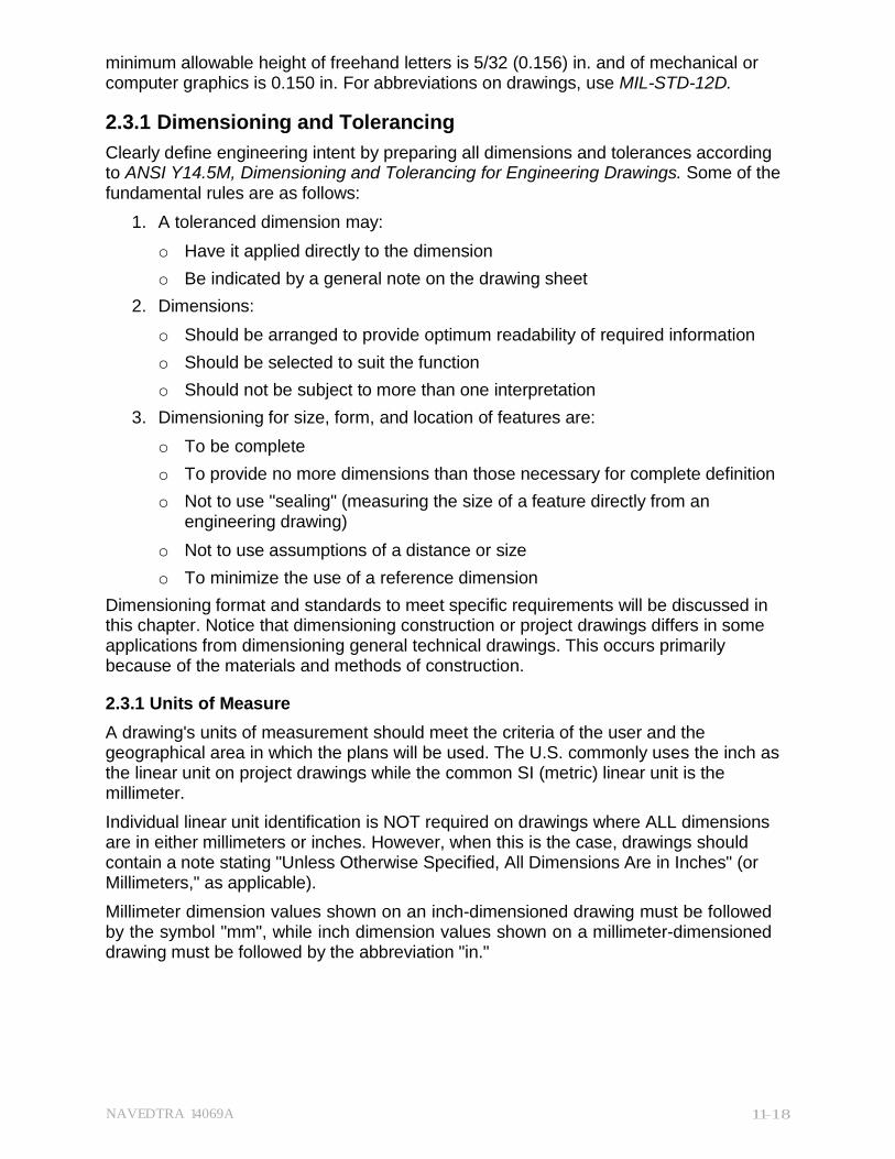
Figure 11-15 – Examples of dimensioning angular units.
Figure 11-15 provides examples of dimensioning angular units.
Dimensions for angular units are expressed in one of two ways:
Degrees, minutes, and seconds, Example A
Degrees and decimal parts of a degree, Example B
2.3.2 Application of Dimensions
Apply dimensions by using dimension lines, extension lines, or a leader from a dimension that includes a note or specification directed to the appropriate feature. Some of the standard rules are as follows:
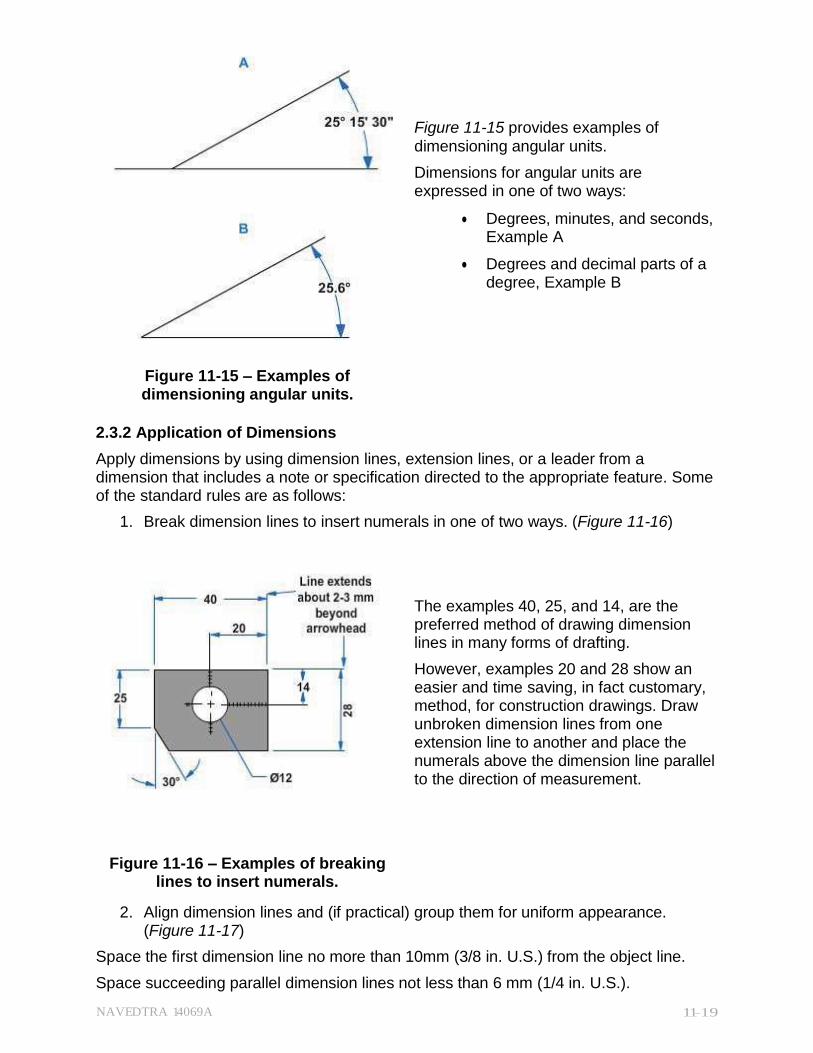
1. Break dimension lines to insert numerals in one of two ways. (Figure 11-16)
The examples 40, 25, and 14, are the preferred method of drawing dimension lines in many forms of drafting.
However, examples 20 and 28 show an easier and time saving, in fact customary, method, for construction drawings. Draw unbroken dimension lines from one extension line to another and place the numerals above the dimension line parallel to the direction of measurement.
Figure 11-16 – Examples of breaking lines to insert numerals.
2. Align dimension lines and (if practical) group them for uniform appearance. (Figure 11-17)
Space the first dimension line no more than 10mm (3/8 in. U.S.) from the object line.
Space succeeding parallel dimension lines not less than 6 mm (1/4 in. U.S.).
NAVEDTRA 14069A 11-20
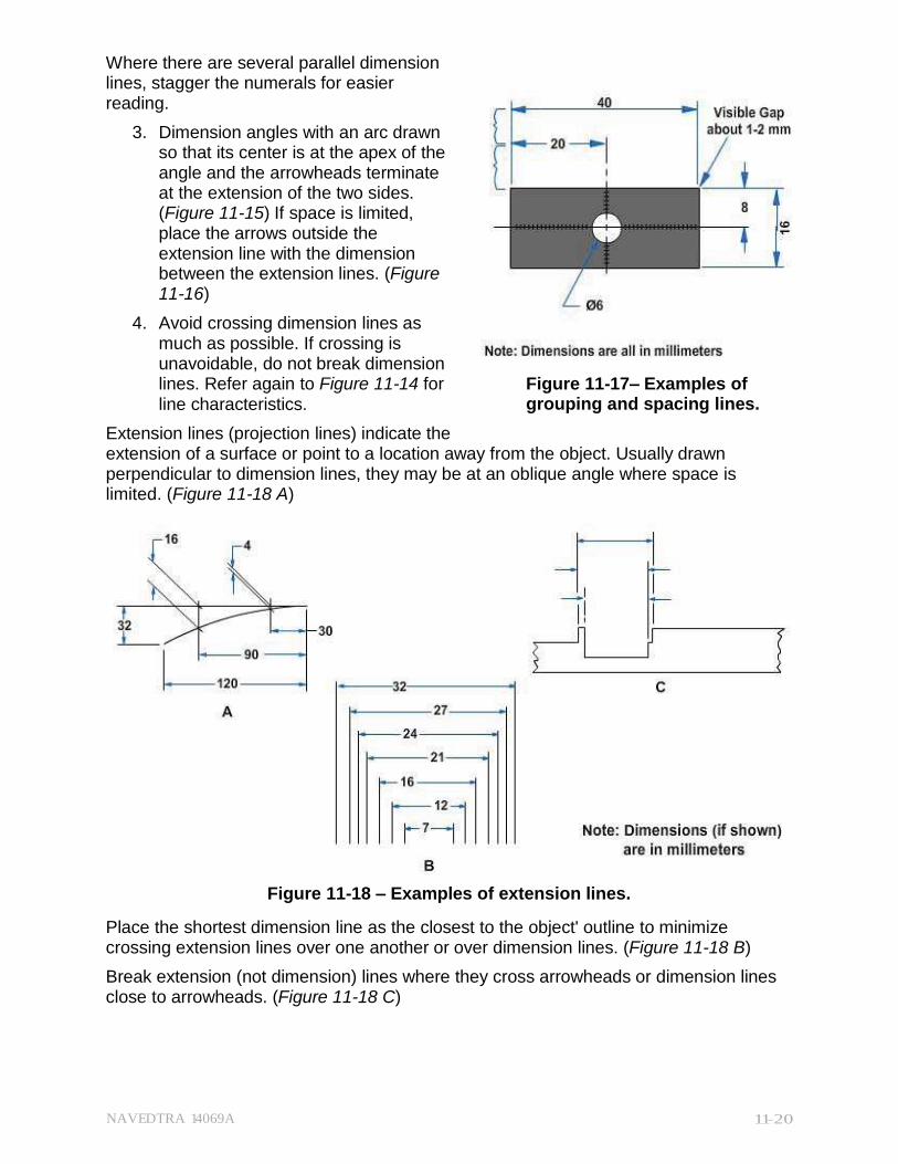
Where there are several parallel dimension lines, stagger the numerals for easier reading.
3. Dimension angles with an arc drawn so that its center is at the apex of the angle and the arrowheads terminate at the extension of the two sides. (Figure 11-15) If space is limited, place the arrows outside the extension line with the dimension between the extension lines. (Figure 11-16)
4. Avoid crossing dimension lines as much as possible. If crossing is unavoidable, do not break dimension lines. Refer again to Figure 11-14 for line characteristics.
Extension lines (projection lines) indicate the
Figure 11-17– Examples of grouping and spacing lines.
extension of a surface or point to a location away from the object. Usually drawn perpendicular to dimension lines, they may be at an oblique angle where space is limited. (Figure 11-18 A)
Figure 11-18 – Examples of extension lines.
Place the shortest dimension line as the closest to the object' outline to minimize crossing extension lines over one another or over dimension lines. (Figure 11-18 B)
Break extension (not dimension) lines where they cross arrowheads or dimension lines close to arrowheads. (Figure 11-18 C)
NAVEDTRA 14069A 11-21
Figure 11-19 – Examples of leader lines.
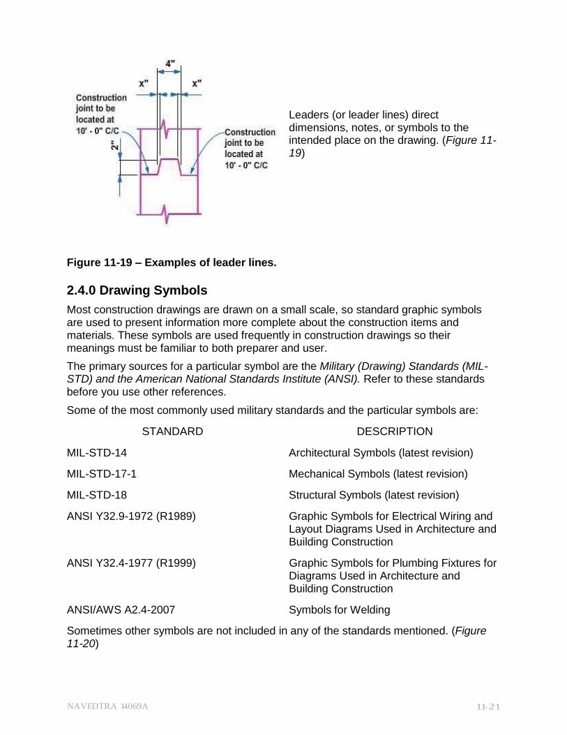
Leaders (or leader lines) direct dimensions, notes, or symbols to the intended place on the drawing. (Figure 11- 19)
2.4.0 Drawing Symbols
Most construction drawings are drawn on a small scale, so standard graphic symbols are used to present information more complete about the construction items and materials. These symbols are used frequently in construction drawings so their meanings must be familiar to both preparer and user.
The primary sources for a particular symbol are the Military (Drawing) Standards (MIL- STD) and the American National Standards Institute (ANSI). Refer to these standards before you use other references.
Some of the most commonly used military standards and the particular symbols are:
STANDARD DESCRIPTION
MIL-STD-14 Architectural Symbols (latest revision)
MIL-STD-17-1 Mechanical Symbols (latest revision)
MIL-STD-18 Structural Symbols (latest revision)
ANSI Y32.9-1972 (R1989) Graphic Symbols for Electrical Wiring and Layout Diagrams Used in Architecture and Building Construction
ANSI Y32.4-1977 (R1999) Graphic Symbols for Plumbing Fixtures for Diagrams Used in Architecture and Building Construction
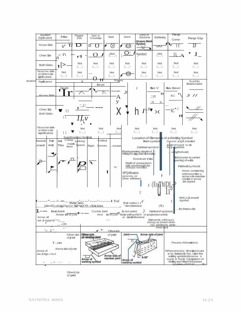
ANSI/AWS A2.4-2007 Symbols for Welding
Sometimes other symbols are not included in any of the standards mentioned. (Figure 11-20)
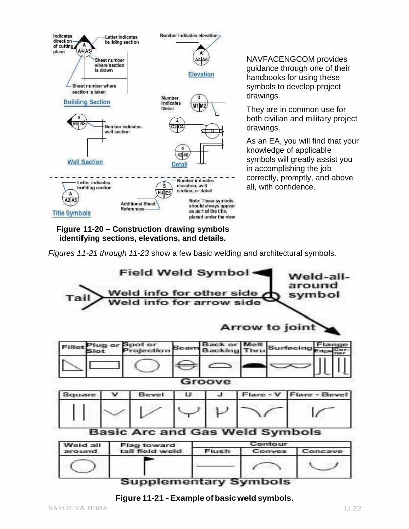
NAVEDTRA 14069A 11-22
Figure 11-21 – Example of basic weld symbols.
NAVFACENGCOM provides guidance through one of their handbooks for using these symbols to develop project drawings.
They are in common use for both civilian and military project drawings.
As an EA, you will find that your knowledge of applicable symbols will greatly assist you in accomplishing the job correctly, promptly, and above all, with confidence.
Figure 11-20 – Construction drawing symbols identifying sections, elevations, and details.
Figures 11-21 through 11-23 show a few basic welding and architectural symbols.
Figure 11-21 - Example of basic weld symbols.
NAVEDTRA 14069A 11-23
Slot Stud Seem
,[>
......
' mable
u
,
o
·
0 I
"
' "
'
Location Significance
Arrow Side
Fillet Ptugor
V' ;ti D
Spot oc
PrnAAM-ion
ti 0
Sack or Sackina Surfacing
roove we1"
Flange
Comer Flange Edge
1f
Other Side /I
I\ rl '
Not O: I Symbol U...t 1- I
Not U...t ' Jl _
Both Sides
Not
U...t
Not
U...t
Not
U...t
Not
U...t
Not
U...t
Not
U...t
Nol
U...t
Not
U...t
No arrow side oc other s de significance
location Significance
Not Not
U...t U...t
v 0
"
Bevel
Not
U...t
Groove u
Not
U...t
Not
U...t
Nol
U...t
Not
U...t
Scarf for Brazed Joint
Square J Flare·V Flare·Bevel
Arrow Side 'Ir JI
A ;;c IC '\
JI //
Other Side
' 1 1 Both Sides
1 1
,::,i:: ---
1Lv ' ,
' ,' •
y :::ti c
JI • c x ' h I\ ')( IC
No arrow side or other s de significance
Not Not
1 1 U...t U...t
Not Not Not Not
U...t U...t U...t U...t
Not
U...t
Supp'8mentary Symbols Location of Elements of a Welding Symbol Weldall Field Melt Consu· a.eking Contour Finish symbol· Groove ang'9, included
around Weld Thru Insert Spacer Flush Convex
p
...oncave
v
Contour symbol-
Root opening:depth of - fillingfor plug andslotwelds
Groove we d size
Depth of preparation; size andstrength for certain weldsl
angle of count rs nk for p ugwelds
....Length of weld
Pitch (center·to.center spacing) of welds
Fieldweldsymbol&
SPQclfication, process, or f other reference
I s (Er{ThIDL-P T 1i°}\
Arrow connecting reference line o arrow s de member of joint or arrow ide of joint
-Wel:l.a.11.around
f-----''----'- -=.,..,,.,-'----'----'------l Tail ( } Basic Joints (Tail omittei;t-1
,_ _ldentificatlo_n__olA_rrow S_id_••n_d_Olh _r_Si_d_e_J_oi_n_t _, hen rsference (N )
&yrrbol
1---- ButtJoint ----+---
Corner Joint ----<
1s not used} ). Numberof spot,stud, ....Re.f•rence line
Arrow side of joint Arro ide of joint Basic weldsymbOl or projection welds Arrow of or detailreference
we d ngsymb"**J
' .,.. -> - Element& n thisarea
remain as shown when tail andarrow are-
" ,..· rewrsed
'<...I..",.. ,r ' Other•ide Other side Arrow
0 ,......, of joint
of j int we d ngsymbol
Arrow of
T - Joint Lap Joint
Arrow side of joint
Edge Joint Process Abbreviations
Where process bbreviations are we d ngs mbof
v ,,.< -.:: ....
Other&1de of joint
to be includedin the. failof the welding symtol,reference is
made to Table I.Designation of Welding andAlliedProcesses
by Letters, of AWS A2 ................. 86.

NAVEDTRA 14069A 11-24
Figure 11-22 - Example of extensive weld symbols and applications.
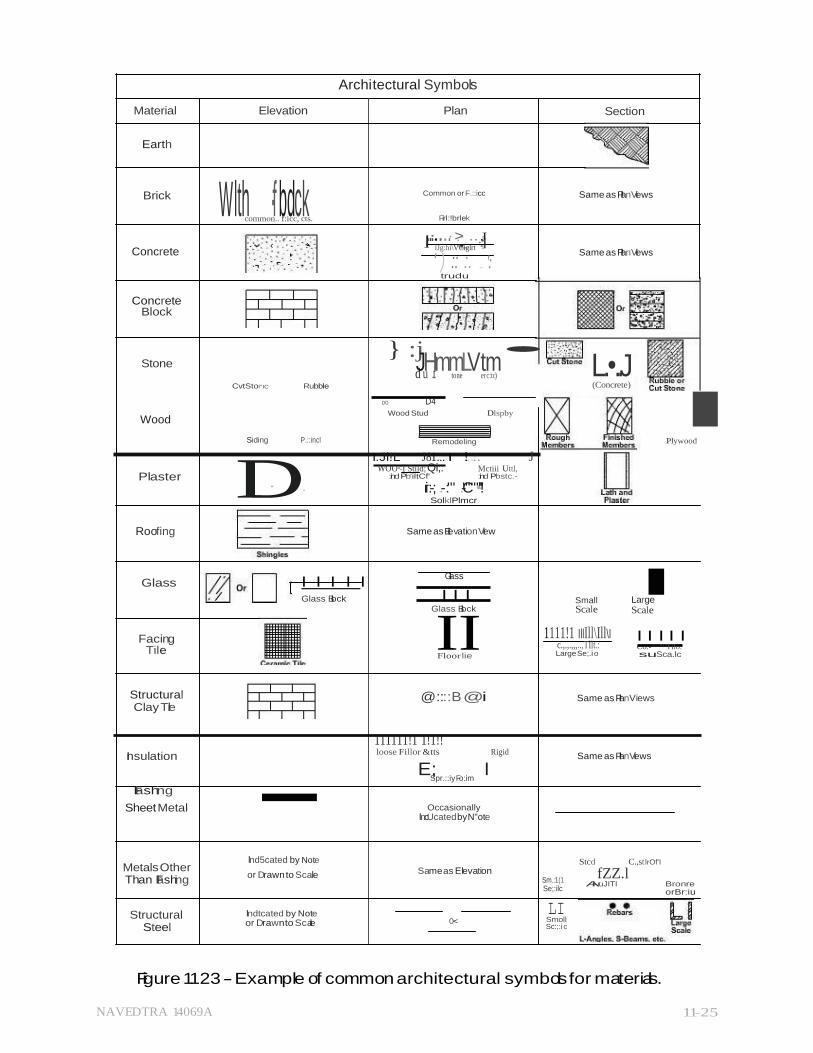
NAVEDTRA 14069A 11-25
Wlth ·f bdck .......
E; I
I
Architectural Symbols
Material Elevation Plan Section
Earth
Brick
common.. f:icc, cts.
Concrete
Concrete Block
Stone
Common or F.::icc
Firl:!brlek
I_·...· >:.·._ ..
·..·:J]
lJg:hi\VCiglrt
' ) :: ·:·. .... ': trudu
} :j • dJ
uH
.tmm
toneLVt
ermc:tc)
Same as PlanViews
Same as PlanViews
L.•..J
Wood
CvtStol"IC Rubble DO D4
Wood Stud Dlspby
(Concrete)
I Siding P.::incl
Plaster D. .
Remodeling
I:Jl!L J81... I !..·.. J WOO<I Stild; Qi;: Mctiii Uttl,
:ind Pb'iltCf' :ind Pbstc.-
ri:-; .-:'" .-C""'•""'·!' SolklPlmcr
Plywood
Roofing Same as Elevation View
Glass
Glass I I I I I
Facing
Tile
Glass Block I I I Glass Block
IFloorIlie
Small Scale
1111!1 IllIll\Ill\I c.,.,.,,,..,Tllt.: Large Se;.i o
Large Scale
I I I I I Co:-'""""Tllo: su Sca.lc
Structural Clay Tile
@::::B @i Same as PlanViews
Insulation
Flashing - 111111!1 1!1!! loose Fillor &tts Rigid
Spr.::iy Fo:im
Same as PlanViews
Sheet Metal Occasionally lncUcated by N"ote
Metals Other Than Flashing
Structural Steel
lnd5cated by Note
or Drawn to Scale Same as Elevation
lndtcated by Note or Drawnto Scale 0<
Sm.:1(1 Se;:ilc
LI Smoll Sc:;:i c
Stcd C.,st lrOf'I
fZZ.l Ai ruJITI Bronre
orBr:iu
Figure 1123 - Example of common architectural symbols for materials.
NAVEDTRA 14069A 11-26
Obviously, there will be many symbols available for use in drawings to communicate the architect and engineers' intentions for the building. As you may be tasked with developing additional drawings from a contract set of drawings, you need to remain aware of the many common symbols' meanings and be able to research any uncommon symbol meaning within your department's technical library.
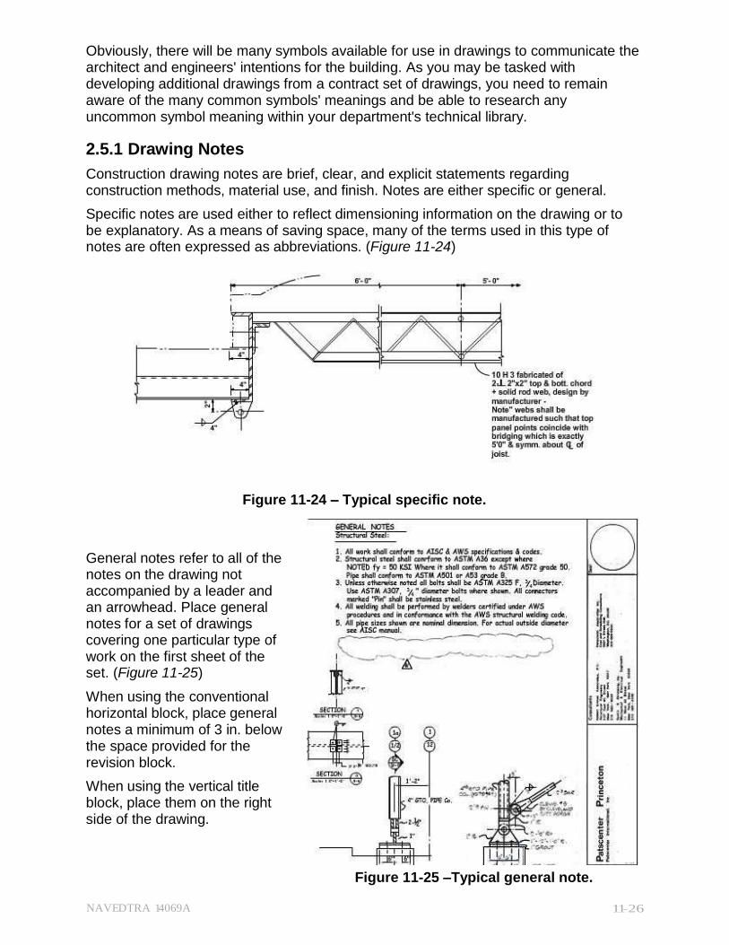
2.5.1 Drawing Notes
Construction drawing notes are brief, clear, and explicit statements regarding construction methods, material use, and finish. Notes are either specific or general.
Specific notes are used either to reflect dimensioning information on the drawing or to be explanatory. As a means of saving space, many of the terms used in this type of notes are often expressed as abbreviations. (Figure 11-24)
Figure 11-24 – Typical specific note. General notes refer to all of the notes on the drawing not accompanied by a leader and an arrowhead. Place general notes for a set of drawings covering one particular type of work on the first sheet of the set. (Figure 11-25)
When using the conventional horizontal block, place general notes a minimum of 3 in. below the space provided for the revision block.
When using the vertical title block, place them on the right side of the drawing.
Figure 11-25 –Typical general note.

NAVEDTRA 14069A 11-27
General notes for architectural and structural drawings may include pertinent data used in the design such as:
Roof, floor, wind, seismic and other loads
Allowable soil pressure or pile-bearing capacity
Allowable unit stresses of all the construction materials
General notes for civil, mechanical, electrical, sanitary, plumbing, or similar groupings may include references for vertical and horizontal control (including soundings) and basic specific design data.
General notes may also refer to a schedule that includes notes grouped together in a tabular form according to the specific construction material or process. Schedules for items like doors, windows, rooms, and footings are somewhat more detailed. Their formats will be presented later in this chapter.
Test your Knowledge (Select the Correct Response)
2. What organization establishes the design criteria for Seabee project drawings?
A. Local sponsoring command B. Naval Facilities Engineering Command (NAVFACENGCOM) C. Local Public Works Center D. Regional Engineering Field Division (EFD)
3.1.1 MAIN DIVISIONS of PROJECT DRAWING
Project drawings (working drawings) are typically divided into the following major categories: civil, architectural, structural, mechanical, electrical, and fire protection. Seabee construction follows the same categories with the exception of fire protection, which is not a common tasking for the NCF.
Regardless of the category, working drawings:
Provide a basis for making material, labor, and equipment estimates before construction begins
Give instructions for construction, showing sizes and locations of various parts
Provide a means of coordination between different ratings
Complement specifications; one source of information is incomplete without the other
3.1.1 Civil Drawings
Civil drawings encompass a variety of plans and information including:
Site preparation and site development
Fencing
Rigid and flexible pavements for roads and walkways
Environmental pollution control
.Water supply units (that is, pumps and wells)
Civil drawings typically begin with a designating letter "C" in the title block. A set can vary from a bare minimum to several sheets depending on the size of the project. On an
NAVEDTRA 14069A 11-28
average-size project, the first sheet will have a location map, soil boring log, legends, and occasionally, site plans and small civil drawing details. (Soil boring tests determine the water table of the construction site and classify the existing soil.)
A site plan furnishes the essential data for laying out the proposed building lines. Drawn from survey notes and sketches, it shows contours, boundaries, roads, utilities, trees, structures, references, and other significant physical features. Civil drawings showing both existing and finished contours enables the initial site crew (Equipment Operators) to estimate the amount of any soil displacement (cut and fill) and prepare the site for construction. It also allows them to plan for the site finishing (including landscaping) upon completion of building construction.
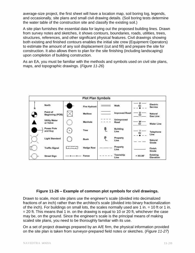
As an EA, you must be familiar with the methods and symbols used on civil site plans, maps, and topographic drawings. (Figure 11-26)
Figure 11-26 – Example of common plot symbols for civil drawings.
Drawn to scale, most site plans use the engineer's scale (divided into decimalized fractions of an inch) rather than the architect's scale (divided into binary fractionalization of the inch). For buildings on small lots, the scales normally used are 1 in. = 10 ft or 1 in. = 20 ft. This means that 1 in. on the drawing is equal to 10 or 20 ft, whichever the case may be, on the ground. Since the engineer's scale is the principal means of making scaled site plans, you need to be thoroughly familiar with its use.
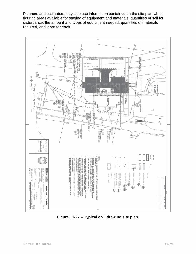
On a set of project drawings prepared by an A/E firm, the physical information provided on the site plan is taken from surveyor-prepared field notes or sketches. (Figure 11-27)
NAVEDTRA 14069A 11-29
Planners and estimators may also use information contained on the site plan when figuring areas available for staging of equipment and materials, quantities of soil for disturbance, the amount and types of equipment needed, quantities of materials required, and labor for each.
Figure 11-27 – Typical civil drawing site plan.

NAVEDTRA 14069A 11-30
As an EA, you may be tasked with drawing a site plan or revising one. The following steps provide the basic procedure to develop a site plan.
1. Lay out the site plan from the surveyor's drawing.
o Show boundary lines or limits of construction.
o Show existing trees and permanent structures.
o Note any existing features that must be removed.
2. Draw contour lines with dashed lines. (Note: Place contour lines on the reverse side of the drafting sheet to make future changes or revisions easier).
3. Draw the proposed building and all surrounding construction, such as sidewalks and parking areas.
o Show building wall outline with solid lines.
o Show roof overhang outline with dashed lines.
4. Give the finished floor elevations of the building(s), garage(s), and desired finish elevations for any sidewalk and/or parking areas.
5. Review the existing contour lines. Surface water must run towards a storm drainage system and not towards the buildings or other structures.
6. Place the dimensions. Establish them from the property line to the exterior wall of the building, not the overhang. Locate the building and other constructions by a minimum of two location dimensions, more if the building is not positioned parallel with the property line. Include distances to road centerlines, utility lines, easements; and any restrictions or obstructions to the site, such as utility poles and hydrants.
7. Double-check your drawing. Take a second look at finish grade elevations, datum point, and other related information.
Keeping a site plan checklist handy is a good technique to make sure a site plan provides complete and accurate information.
3.2.1 Architectural Drawings
Architectural drawings typically begin with a designating letter "A" in the title block. They consist of all the drawings that describe the architectural design and composition of the building. A complete set of architectural drawings include:
Floor plans
Building sections
Exterior and interior elevations
Millwork
Door and window details and schedules
Interior and exterior finish schedules
Any special architectural treatments
For small, uncomplicated buildings, architectural drawings may include foundation and framing plans, normally part of the structural drawings.

NAVEDTRA 14069A 11-31
3.2.1 Floor Plan
Floor plans are considered the key drawings in a set of project drawings-the drawings that all of the construction personnel will look at and usually the first drawing an EA will work on.
A floor plan is a horizontal section through a building, showing the outline or arrangement of the floor. An offset cutting plane is often required to pass through low and high features on the wall in order to reveal features located in the building.
Its purpose is to show information about the:
Footprint of the structure(s) relative to the property
Type of construction
Location and size of doors and windows
Built-in fireplaces
Stairs
Rooms
Exterior and interior features
Figure 11-28 shows a typical floor plan development. Imagine that after the building's completion, a cutting plane passes through point WXYZ.
Figure 11-28 – Typical simple floor plan development.
NAVEDTRA 14069A 11-32
Note that the WXYZ plane passes through at an elevation that includes all the distinctive elements, the windows and doors. If the plane passed through the building above the door height, the floor plan would look like a solid box with closed interior cells.
With the upper portion of the cutting plane removed, you are now able to look down on a floor plan that includes all the doors and windows you were previously unable to see.
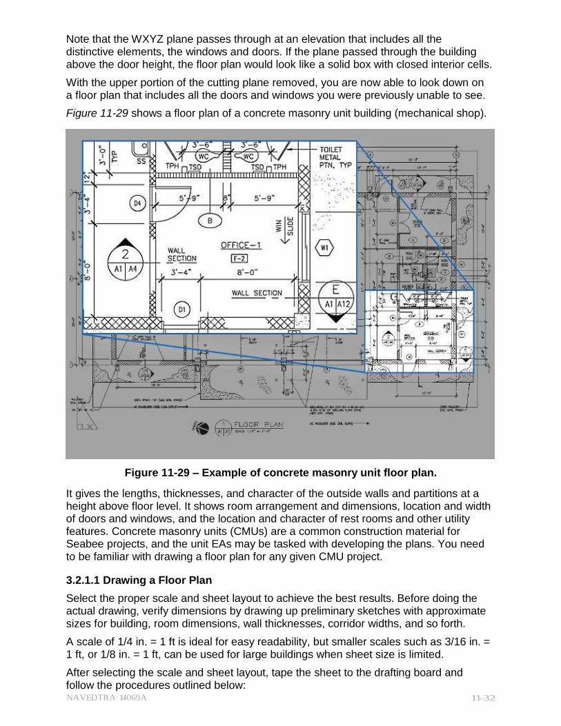
Figure 11-29 shows a floor plan of a concrete masonry unit building (mechanical shop).
Figure 11-29 – Example of concrete masonry unit floor plan.
It gives the lengths, thicknesses, and character of the outside walls and partitions at a height above floor level. It shows room arrangement and dimensions, location and width of doors and windows, and the location and character of rest rooms and other utility features. Concrete masonry units (CMUs) are a common construction material for Seabee projects, and the unit EAs may be tasked with developing the plans. You need to be familiar with drawing a floor plan for any given CMU project.
3.2.1.1 Drawing a Floor Plan
Select the proper scale and sheet layout to achieve the best results. Before doing the actual drawing, verify dimensions by drawing up preliminary sketches with approximate sizes for building, room dimensions, wall thicknesses, corridor widths, and so forth.
A scale of 1/4 in. = 1 ft is ideal for easy readability, but smaller scales such as 3/16 in. = 1 ft, or 1/8 in. = 1 ft, can be used for large buildings when sheet size is limited.
After selecting the scale and sheet layout, tape the sheet to the drafting board and follow the procedures outlined below:
NAVEDTRA 14069A 11-33
1. Lay out the drawing construction lines for borders, title block, and exterior limits of the building at any one side.
o Draw exterior wall thicknesses first and lay out the rooms and walls from left to right.
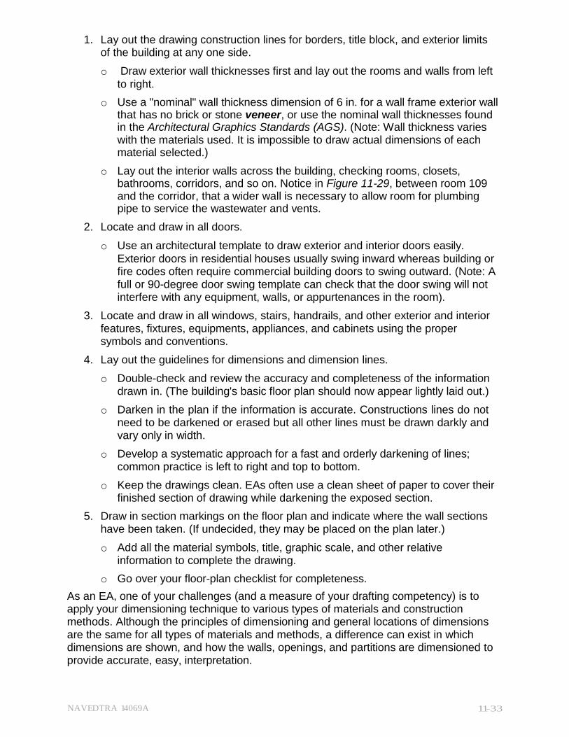
o Use a "nominal" wall thickness dimension of 6 in. for a wall frame exterior wall that has no brick or stone veneer, or use the nominal wall thicknesses found in the Architectural Graphics Standards (AGS). (Note: Wall thickness varies with the materials used. It is impossible to draw actual dimensions of each material selected.)
o Lay out the interior walls across the building, checking rooms, closets, bathrooms, corridors, and so on. Notice in Figure 11-29, between room 109 and the corridor, that a wider wall is necessary to allow room for plumbing pipe to service the wastewater and vents.
2. Locate and draw in all doors.
o Use an architectural template to draw exterior and interior doors easily. Exterior doors in residential houses usually swing inward whereas building or fire codes often require commercial building doors to swing outward. (Note: A full or 90-degree door swing template can check that the door swing will not interfere with any equipment, walls, or appurtenances in the room).
3. Locate and draw in all windows, stairs, handrails, and other exterior and interior features, fixtures, equipments, appliances, and cabinets using the proper symbols and conventions.
4. Lay out the guidelines for dimensions and dimension lines.
o Double-check and review the accuracy and completeness of the information drawn in. (The building's basic floor plan should now appear lightly laid out.)
o Darken in the plan if the information is accurate. Constructions lines do not need to be darkened or erased but all other lines must be drawn darkly and vary only in width.
o Develop a systematic approach for a fast and orderly darkening of lines; common practice is left to right and top to bottom.
o Keep the drawings clean. EAs often use a clean sheet of paper to cover their finished section of drawing while darkening the exposed section.
5. Draw in section markings on the floor plan and indicate where the wall sections have been taken. (If undecided, they may be placed on the plan later.)
o Add all the material symbols, title, graphic scale, and other relative information to complete the drawing.
o Go over your floor-plan checklist for completeness.
As an EA, one of your challenges (and a measure of your drafting competency) is to apply your dimensioning technique to various types of materials and construction methods. Although the principles of dimensioning and general locations of dimensions are the same for all types of materials and methods, a difference can exist in which dimensions are shown, and how the walls, openings, and partitions are dimensioned to provide accurate, easy, interpretation.
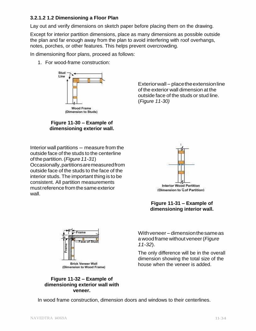
NAVEDTRA 14069A 11-34
3.2.1.2 1.2 Dimensioning a Floor Plan
Lay out and verify dimensions on sketch paper before placing them on the drawing.
Except for interior partition dimensions, place as many dimensions as possible outside the plan and far enough away from the plan to avoid interfering with roof overhangs, notes, porches, or other features. This helps prevent overcrowding.
In dimensioning floor plans, proceed as follows:
1. For wood-frame construction:
Exterior wall - place the extension line of the exterior wall dimension at the outside face of the studs or stud line. (Figure 11-30)
Figure 11-30 – Example of dimensioning exterior wall.
Interior wall partitions - measure from the outside face of the studs to the centerline of the partition. (Figure 11-31) Occasionally, partitions are measured from outside face of the studs to the face of the interior studs. The important thing is to be consistent. All partition measurements must reference from the same exterior wall.
Figure 11-31 – Example of dimensioning interior wall.
With veneer - dimension the same as a wood frame without veneer (Figure 11-32).
The only difference will be in the overall dimension showing the total size of the house when the veneer is added.
Figure 11-32 – Example of dimensioning exterior wall with
veneer.
In wood frame construction, dimension doors and windows to their centerlines.
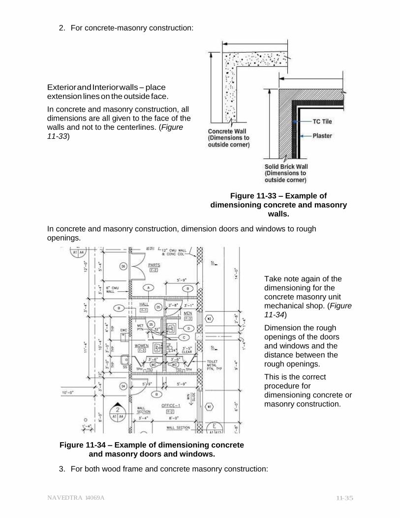
NAVEDTRA 14069A 11-35
2. For concrete-masonry construction:
Exterior and Interior walls - place extension lines on the outside face.
In concrete and masonry construction, all dimensions are all given to the face of the walls and not to the centerlines. (Figure 11-33)
Figure 11-33 – Example of
dimensioning concrete and masonry walls.
In concrete and masonry construction, dimension doors and windows to rough openings.
Take note again of the dimensioning for the concrete masonry unit mechanical shop. (Figure 11-34)
Dimension the rough openings of the doors and windows and the distance between the rough openings.
This is the correct procedure for dimensioning concrete or masonry construction.
Figure 11-34 – Example of dimensioning concrete and masonry doors and windows.
3. For both wood frame and concrete masonry construction:
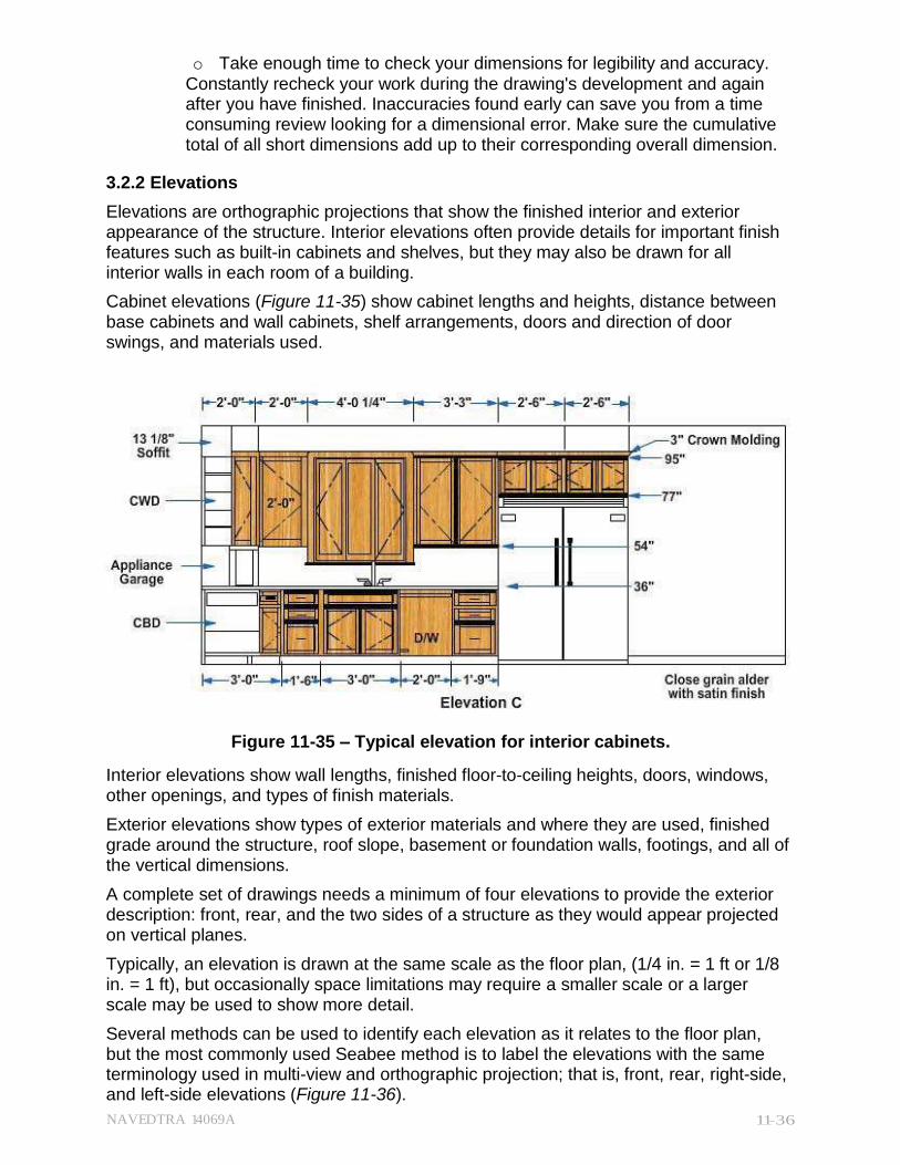
NAVEDTRA 14069A 11-36
o Take enough time to check your dimensions for legibility and accuracy. Constantly recheck your work during the drawing's development and again after you have finished. Inaccuracies found early can save you from a time consuming review looking for a dimensional error. Make sure the cumulative total of all short dimensions add up to their corresponding overall dimension.
3.2.2 Elevations
Elevations are orthographic projections that show the finished interior and exterior appearance of the structure. Interior elevations often provide details for important finish features such as built-in cabinets and shelves, but they may also be drawn for all interior walls in each room of a building.
Cabinet elevations (Figure 11-35) show cabinet lengths and heights, distance between base cabinets and wall cabinets, shelf arrangements, doors and direction of door swings, and materials used.
Figure 11-35 – Typical elevation for interior cabinets.
Interior elevations show wall lengths, finished floor-to-ceiling heights, doors, windows, other openings, and types of finish materials.
Exterior elevations show types of exterior materials and where they are used, finished grade around the structure, roof slope, basement or foundation walls, footings, and all of the vertical dimensions.
A complete set of drawings needs a minimum of four elevations to provide the exterior description: front, rear, and the two sides of a structure as they would appear projected on vertical planes.
Typically, an elevation is drawn at the same scale as the floor plan, (1/4 in. = 1 ft or 1/8 in. = 1 ft), but occasionally space limitations may require a smaller scale or a larger scale may be used to show more detail.
Several methods can be used to identify each elevation as it relates to the floor plan, but the most commonly used Seabee method is to label the elevations with the same terminology used in multi-view and orthographic projection; that is, front, rear, right-side, and left-side elevations (Figure 11-36).
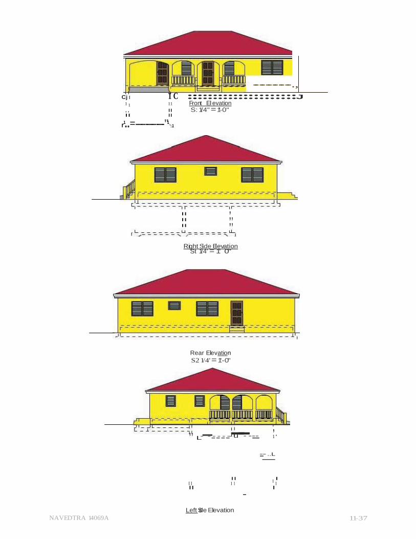
NAVEDTRA 14069A 11-37
,, ,, ,,
------------.,
Cj I 1 C :::::::::::::::::::::J 1 1 11 Front El evation , , II S: 1/4" = 1'-0" II II
r1..=-----------"1
':.1
II
II
II
Right Si de El evation St 1/4' = 1' 0"
Rear Elevation
S2 1/4' = 1'-0"
,, L------------- u-- -----
, 1 '
--_- ..L
II I I I 1 1
1 1
II I
-
Left Side Elevation

NAVEDTRA 14069A 11-38
S2 1/4' = 1'-0"
Figure 11-36 - Typical elevations for exterior views.
NAVEDTRA 14069A 11-39
On irregular plans that would not clearly show an orthographic projection from one of the four views, elevations may be identified by a letter or a number. (Figure 11-37)
Figure 11-37 – Example of an elevation view for an irregular floor plan.
Use the following basic procedures as a guide to develop and draw elevations:
1. Use the same size sheet as the floor plan.
o Determine overall height and length of elevations from floor plan and wall section (predetermined by prior computation or a sketch).
o Use the same scale for elevations as for floor plan unless there is a specific benefit to a different scale.
o Block in the views with construction lines placed in a logical order starting with the front view and working around the building. Front and right-side elevations are usually next to each other with (if necessary) the rear and the left-side elevations below.
o Show all elevations on one sheet whenever possible.
2. Draw the exterior limits of the elevations.
o Place the floor plan underneath the elevation-drafting sheet for a guide.
o The vertical projection lines from the floor plan will define the length of exterior walls and any breaks or corners along the wall, windows, doors, roof overhang, and other elements, such as chimney location.
o Horizontal projection lines on your elevation drawing will locate the height of doors and windows, eave line, bottom of fascia, top and bottom of the footing, and top of the roof.
3. Repeat until all elevations are lightly laid out with final changes incorporated into the exterior design.
o Darken the drawing from left to right, top to bottom (same procedures used in the floor plan).
o Remember, the grade line is the darkest line (disregarding the border lines), and all portions drawn below grade are shown with a dark hidden line.
NAVEDTRA 14069A 11-40
4. Add dimensions.
o Show vertical dimensions (include the following only): bottom of footing, finished grade, all finished floor lines, height of features, finished ceiling lines, chimney height, and freestanding walls. Refer to Chapter 4 for additional information.
5. Add all notes and pertinent information about exterior materials such as finishes, title, scale, window identification marks, and roof pitch.
o Add section symbols to indicate where the sections have been taken. (Figure 11-38, View A)
6. Finish up by adding the material symbols. (Figure 11-38, View B)
o Symbols do not take the place of the material notations; they just supplement them.
o Go over your elevation checklist for completeness and accuracy of information.
Figure 11-38 – Section symbols-View A, Material symbols-View B.
3.3.0 Structural Drawings
Structural drawings typically begin with a designating letter "S" in the title block. A complete set contains all drawings relating to the building's structural members and their interacting relationship. A set of structural drawings should include foundation plans and details, framing plans and details, wall sections, column and beam details, and all other plans, sections, details, and schedules necessary.
General notes in structural drawings should include, when applicable, all roof, floor, wind, seismic, and other loads, along with allowable soil pressure or pile bearing capacity and allowable stresses of all material used in the design.
3.3.1 lan
A foundation plan is a top view of footings or foundation walls. Actually a horizontal section view cut through the walls of the foundation just below ground floor level, it shows beams, girders, piers or columns, openings, internal composition, and dimensions with centerlines and distances from reference or boundary lines.
NAVEDTRA 14069A 11-41
A foundations plan's primary user will be the building crew that constructs the proposed structure's foundation. Most foundations in Seabee construction are built with concrete masonry units (CMU) and/or cast-in-place concrete.
Figure 11-39 shows a plan view of a concrete/CMU foundation. The plan shows the main foundation will consist of 12 in. CMU walls measuring 28 ft by 22 ft. above a concrete spread footing that is 24 in. wide by 10 in. deep. In this plan, the standard symbol for concrete block identifies the CMU but a specific note should be added to call out the material.
Figure 11-39 – Typical foundation plan for CMU footing.
A girder will run through the center of the building, supported on both ends by a 4 by 12 in. concrete pilaster abutting the foundation walls with intermediate support from two 12 by 12 in. concrete piers on 18 by 18 in. spread footings 10 in. deep.
Before you can draw the foundation plan, you will need to gather all relevant information about the concept of the structure. Observe the type of foundation intended, make a careful study of the materials and methods to be used, and analyze the relative position of the framing to the foundation wall or footing.
Before you start, refer to all of the applicable wall sections and typical sill details found in your texts and reference materials such as the Architectural Graphics Standards. Note: Two sides of the footing in Figure 11-39 show concrete sills to support the joists. Did you see that without the A-A elevation detail?
NAVEDTRA 14069A 11-42
The ground floor plan serves as the basis for developing the foundation plan, (just as it did for the elevation views). The floor plan readily offers the information you need, such as the general shape of the building, openings, dimensions, and so forth.
Use the following basic procedures to develop a foundation plan properly:
1. Prepare and organize your drafting needs.
o Draw the foundation plan at the same scale as the floor plan (1/4 in. = 1 ft), with the same sheet size and layout. Drawing the foundation plan by this method is easier because you can save time and effort by tracing the floor plan's outline and other features.
o Center the foundation plan to provide more space for notes and details about the footings. A smaller scale may be used when necessary to save space provided the amount of information given on this plan is limited.
2. Lay out the drafting sheet lightly, beginning with the borders and title block.
o Tape a floor plan (original or preferably a print) under the foundation sheet if using the same scale.
o Draw the exterior outline of the foundation wall (usually the outside, exterior line of the building), and locate any retaining walls, steps, porches, and fireplaces.
o Carefully note the type of frame construction that will be used. Using the floor plan in laying out the foundation plan will vary among wood-frame, masonry, and steel-frame construction. Study these differences closely. Usually, a foundation plan's dimensions are modified depending on the materials used.
o If drawing to a different scale, determine the size of the desired foundation plan and lay it out on the sheet. Follow up by transferring all of the dimensions from the floor plan to the foundation plan. Be especially careful to locate other features accurately with the different scale.
3. Draw the inside wall of the foundation wall once the wall thickness is scaled from the established outside foundation line.
o Locate other features such as access doors, vents, and pilasters. Also, draw the foundation for piers, columns, chimney, and any retaining wall, if required.
4. Lay out the footings.
o Check the standards for typical details on different types of footings and the minimum allowable footing size for intended type of frame construction.
o Draw and note any required additional structural information. For example, in wood-frame construction, the foundation plan commonly shows the structural information for the first floor as well. If so required, locate and lay in the supporting beam or girder and the size, spacing, and direction of floor joists.
5. Lay out the dimensions.
o Double-check all dimensions to ensure they are correct, complete, and include all the features required in the drawing.
o Add all of the notes, materials, appropriate plan symbols, and other pertinent information required to complete the plan.
6. Draw in the scale to the plan and the title of the drawing. Review your foundation- plan checklist, and make sure the entire drawing is darkened in and labeled.
NAVEDTRA 14069A 11-43
3.3.2 Framing Plan
Framing plans show the size, number, and location of either steel or wood structural members. Separate framing plans may be drawn for the floors, the walls, and the roof.
Floor framing plans must specify the sizes and spacing of joists, girders, and columns used to support the floor.
If necessary, add detail drawings to show the methods of anchoring joists and girders to the columns and foundation walls or footings. (Figure 11-40)
Figure 11-40 – Typical detail for anchoring joist.
The floor framing plan is a plan view of the layout of girders, beams, and joists. Figure 11-41 shows a typical floor framing plan.
NAVEDTRA 14069A 11-44
Figure 11-41 – Example of a structural upper floor, wood frame plan.
Joists and double framing are drawn in the position they will occupy in the completed building. Joists do not need dimensions at every location. Notes provide the necessary information, in this case "2" by 8" joists @ 16" O.C." (on center).
Bridging is also drawn in position perpendicular to the joist but called out by note as "2- 1" x 3" bridging". The span of the joist controls the number of required rows of cross bridging. The rows should not be more than 7 or 8 ft apart. Hence, a 14-ft span may need only one row of bridging, but a 16-ft span needs two rows. Notes also identify floor openings, trimmers, plates, or doubles to support heavier floor loads.
Floor framing plans do not indicate length dimensions for individual pieces. The builder is able to determine those from overall building dimensions, dimensions for each bay, or distances between columns or posts.
Wall framing plans (Figure 11-42) show the location and method of framing openings and ceiling heights so that studs and posts can be cut.
NAVEDTRA 14069A 11-45
Figure 11-42 – Example of a structural wall, wood frame plan.
Roof framing plans for wood frame construction are drawn in the same manner as the floor framing plan. The rafters are shown in the same manner as joists, with rafters shown spanning the building and supporting the roof. The size, spacing, roof slope, and all of the details are also shown in the plan. (Figure 11-43)
Roof framing plans for precast or cast-in-place concrete construction should indicate with symbols the location of:
Bearing walls
Beams and columns
Direction and size of steel reinforcing bars
The direction of the span
Size and thickness of required structural members
Figure 11-44 shows an example of a cast-in-place structural roof framing plan with beams, joists, metal deck, welded wire fabric, schedule, and general notes.
...
....
- CJ
IO:S:::I
,, . . w
.g
:e
z
rn 0 --l
... .,, 0 -·
"<D
' ccc )>
ID
.... ' w I
Ill
NOTE: All rafters 2'"x8" @ 16" o.c.
Trimmers Continue to
Building Line
., 12"x10" Ridge.
Partition Plate Below "- II
ID -Ridgen. Valle Rafte ,, "
2. Ill
".c.'.
. .
2"x8" Rafters ,,
2"x1O" Rid e h Valley.Jacks
NValley RafterI
iil _...
Ridge Board .
II II 11 II I I
Rafters Staggered r l2"x6" Rafters to line up wlth
II I 1, Doubl:e 2"x8"
Wimmers 0 0 Q.
::;- Ill
3 ID
I II I II
lBuilding Line I
ceiling joist Double 2"x8'
2-2 "x4" Plate below v Tr mmers Ridge
iii" ?
t
l2"x6" Rafters 1"x8" laid flatwise to support entry rafters
Roof Frami ng Pl an Scale: 1/4" = 1'-0"
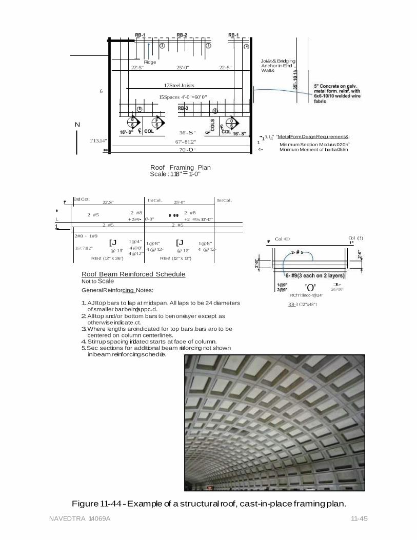
NAVEDTRA 14069A 11-45
Ridge
22'-5" 25'-0" 22'-5"
17 Steel Joists
6
15 Spaces 4'-0"=60' 0"
Joi&t & Bridging Anchor inEnd , Wall&
N
36'- s·
••13,14" "MetalForm Desi gn Requi rement&:
1' 13,14"
•• 67'- 8112"
70'- o·
Roof Framing Plan Scale : 118" = 1'-0"
1 Minimum Section Modulus:.020in1
4• Minimum Moment of Inertia:.055in
,. End Cot.
22'.S"
Int Col .
25'-0"
Int Col .
2 #5 2 #8 2 #8 • ...
L + 2#9• 10'-0" +2 #9x 10'-0'"
;L 2 #5 2 #5
2#8 + 1#9
[J 1@4" 1@8" [J 1@8"
,. Col ©
,C.ol (!)
1@: 7 112" @ 15"
4 @8" 4 @12· @ 15" 4 @12· 4 @12'"
RB-2 (12" x 36'"} RB-2 (12" x 13'"}
Roof Beam Reinforced Schedule Not to Scale
GeneralReinforcing Notes:
1. AJItop bars to lap at midspan. All laps to be 24 diameters of smaller bar beinglappc.d.
2. All top and/or bottom bars to bein onelayer except as otherwise indicate.ct.
3. Where lengths aroindicated for top bars,bars aro to be centered on column centerlines.
4. Stirrup spacing indicated starts at face of column. 5.Sec sections for additional beam reinforcing not shown
in beam reinforc ing schedule.
'O'
RCfT'l:llndc-r@24"
RB-3 C12"x48"1
1·
2@18"
Figure 11-44 - Example of a structural roof, cast-in-place framing plan.
NAVEDTRA 14069A 11-46
Use the following procedures when preparing framing plans:
1. For roof wood-frame plans:
o Trace or transfer the dimensions and location of exterior stud wall.
o Lay out the limits of roof overhang.
o Lay out roof framing by locating the ridgeboard.
o Lay out all of the required intersecting pieces.
2. For floor wood-frame plans:
o Transfer dimensions of the foundation walls or footings.
o Lay out supporting girders and joists in their proper spacing.
o Notice any bearing wails, stairwells, and other openings when developing an elevated-floor framing plan.
3. For concrete framing plans:
o Lay out the dimensions of the bearing walls below the floor (or roof) being framed, for example, a foundation plan to draw the first-floor framing or first- floor plan to draw the second-floor framing.
o Add the location of beams, columns, direction of the span, size of precast concrete, or reinforcing steel for cast-in-place concrete.
4. For steel framing plans:
o Trace off or transfer the dimensions of all of the bearing walls, columns, and beams below the floor (or roof) being framed.
o Lay out the steel framing, using the grid system, a common setup used in steel framing.
5. For all framing plans whether wood, concrete, or steel, to finish:
o Lay out guidelines for dimensions, notes, and labels.
o Darken in all of the framing and fill in the notes and dimensions
o Draw in the section and detail marks.
o Go over your structural plans checklist and check the dimensions against those traced from the floor plan.
3.4.1 Mechanical Drawings
Chapter 9 provides symbols for components associated with mechanical systems and describes methods used to develop a mechanical plan. This section will focus on applicable procedures for drawing residential or commercial building plumbing plans.
A separate mechanical plan is drawn for some residences and commercial structures. They show water supply and fixtures, waste disposal lines, equipment such as hot water tank or recirculation hot water loop, and other supply and disposal sources.
Apply the following procedures to draw a plumbing plan:
1. Trace the floor plan, showing all exterior and interior walls, major appliances, and plumbing fixtures.
o Draw the outline of the building in thin but visible lines.
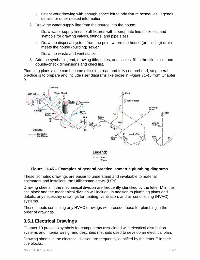
NAVEDTRA 14069A 11-47
o Orient your drawing with enough space left to add fixture schedules, legends, details, or other related information.
2. Draw the water-supply line from the source into the house.
o Draw water supply lines to all fixtures with appropriate line thickness and symbols for drawing valves, fittings, and pipe sizes.
o Draw the disposal system from the point where the house (or building) drain meets the house (building) sewer.
o Draw the waste and vent stacks.
3. Add the symbol legend, drawing title, notes, and scales; fill in the title block, and double-check dimensions and checklist.
Plumbing plans alone can become difficult to read and fully comprehend, so general practice is to prepare and include riser diagrams like those in Figure 11-45 from Chapter 9.
Figure 11-45 – Examples of general practice isometric plumbing diagrams.
These isometric drawings are easier to understand and invaluable to material estimators and installers, the Utilitiesman crews (UTs).
Drawing sheets in the mechanical division are frequently identified by the letter M in the title block and the mechanical division will include, in addition to plumbing plans and details, any necessary drawings for heating, ventilation, and air conditioning (HVAC) systems.
These sheets containing any HVAC drawings will precede those for plumbing in the order of drawings.
3.5.1 Electrical Drawings
Chapter 10 provides symbols for components associated with electrical distribution systems and interior wiring, and describes methods used to develop an electrical plan.
Drawing sheets in the electrical division are frequently identified by the letter E in their title blocks.
NAVEDTRA 14069A 11-48
When working with electricity, a simple Operational Risk Management (ORM) process will conclude that it is important for EAs not only to understand electrical symbols and drafting methods, but also to learn a great deal about how the system works. EAs must also recognize the need for the safety requirements of the system and the minimum requirements of the National Electrical Code (NEC) and any local codes that apply to the drawing.
Use the same procedures to draw an electrical plan as were applied to the mechanical plan; for example, use correct line thickness and orientation and employ standard symbols as much as possible.
1. After the floor plan is traced (see mechanical):
o Draw the meter and service panel noting voltage rating and amperage.
o Draw convenience outlets, ceiling and wall fixtures, and other electrical devices.
2. Draw switches.
o Connect switches to fixtures or convenience outlets using a template or a french curve (curved lines may be solid or dashed and included in symbols list).
o Add circuits, circuit numbers, and circuit notations.
3. Add symbol legend and fixture legend (if required), drawing title, scale, fill in the title block, and as usual, go over the drawing for completeness and accuracy.
3.6.1 Sections
Sections most commonly apply to the architectural and structural divisions but they can be used in any division to amplify information as necessary. Sections show the type of construction required, types of materials, locations, and method of assembling the building parts.
Although they may be used in each of the divisions and are important to those responsible for that division, perhaps the most important of all are wall sections found in the structural drawings.
Wall sections, commonly drawn at a scale of 3/4 in. = 1 ft, provide a wealth of information necessary to understand the structural arrangement, construction methods, and material composition of the walls of the building. (Figure 11-46) They are used extensively to visualize both the engineered requirements of the wall support system and architectural requirements of the building's finish.
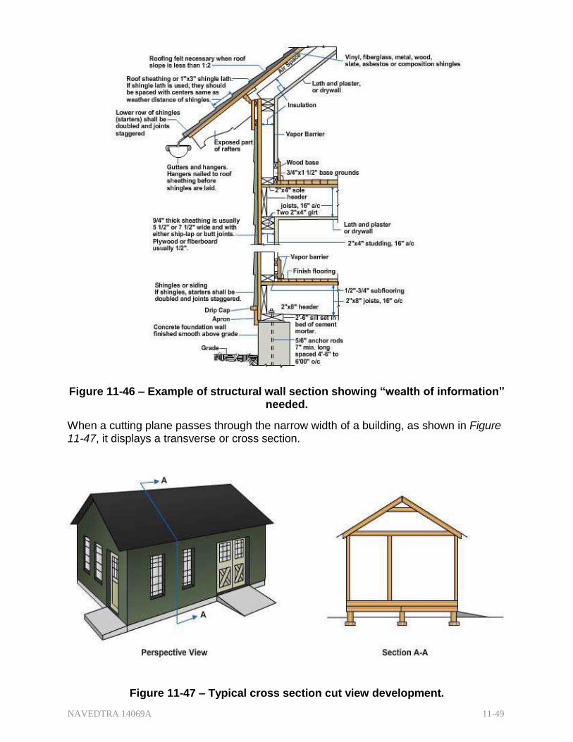
NAVEDTRA 14069A 11-49
Figure 11-46 – Example of structural wall section showing “wealth of information” needed.
When a cutting plane passes through the narrow width of a building, as shown in Figure 11-47, it displays a transverse or cross section.
Figure 11-47 – Typical cross section cut view development.
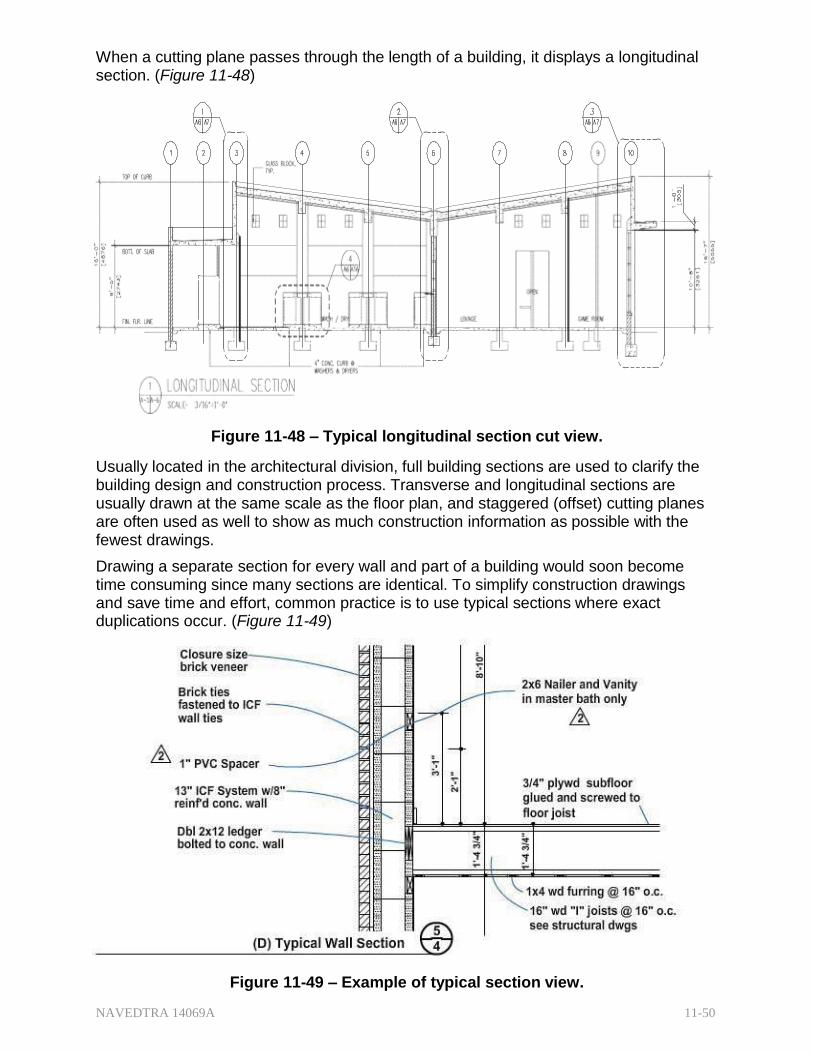
NAVEDTRA 14069A 11-50
When a cutting plane passes through the length of a building, it displays a longitudinal section. (Figure 11-48)
Figure 11-48 – Typical longitudinal section cut view.
Usually located in the architectural division, full building sections are used to clarify the building design and construction process. Transverse and longitudinal sections are usually drawn at the same scale as the floor plan, and staggered (offset) cutting planes are often used as well to show as much construction information as possible with the fewest drawings.
Drawing a separate section for every wall and part of a building would soon become time consuming since many sections are identical. To simplify construction drawings and save time and effort, common practice is to use typical sections where exact duplications occur. (Figure 11-49)
Figure 11-49 – Example of typical section view.
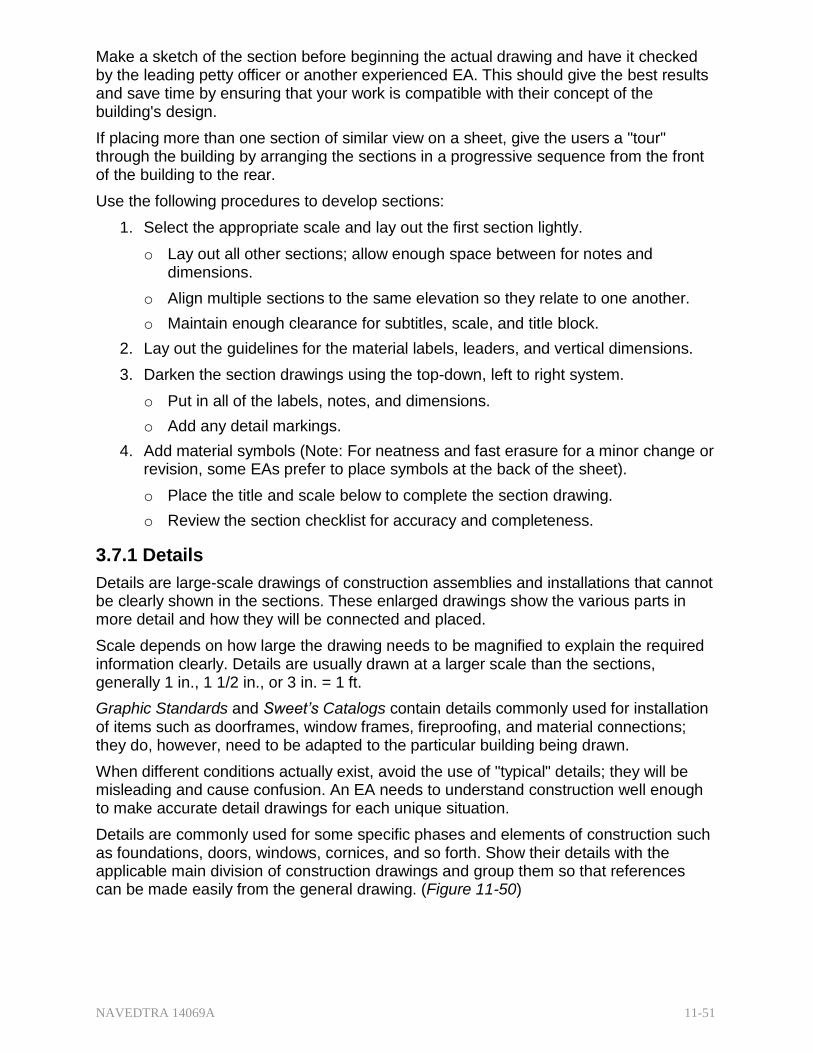
NAVEDTRA 14069A 11-51
Make a sketch of the section before beginning the actual drawing and have it checked by the leading petty officer or another experienced EA. This should give the best results and save time by ensuring that your work is compatible with their concept of the building's design.
If placing more than one section of similar view on a sheet, give the users a "tour" through the building by arranging the sections in a progressive sequence from the front of the building to the rear.
Use the following procedures to develop sections:
1. Select the appropriate scale and lay out the first section lightly.
o Lay out all other sections; allow enough space between for notes and dimensions.
o Align multiple sections to the same elevation so they relate to one another.
o Maintain enough clearance for subtitles, scale, and title block.
2. Lay out the guidelines for the material labels, leaders, and vertical dimensions.
3. Darken the section drawings using the top-down, left to right system.
o Put in all of the labels, notes, and dimensions.
o Add any detail markings.
4. Add material symbols (Note: For neatness and fast erasure for a minor change or revision, some EAs prefer to place symbols at the back of the sheet).
o Place the title and scale below to complete the section drawing.
o Review the section checklist for accuracy and completeness.
3.7.1 Details
Details are large-scale drawings of construction assemblies and installations that cannot be clearly shown in the sections. These enlarged drawings show the various parts in more detail and how they will be connected and placed.
Scale depends on how large the drawing needs to be magnified to explain the required information clearly. Details are usually drawn at a larger scale than the sections, generally 1 in., 1 1/2 in., or 3 in. = 1 ft.
Graphic Standards and Sweet’s Catalogs contain details commonly used for installation of items such as doorframes, window frames, fireproofing, and material connections; they do, however, need to be adapted to the particular building being drawn.
When different conditions actually exist, avoid the use of "typical" details; they will be misleading and cause confusion. An EA needs to understand construction well enough to make accurate detail drawings for each unique situation.
Details are commonly used for some specific phases and elements of construction such as foundations, doors, windows, cornices, and so forth. Show their details with the applicable main division of construction drawings and group them so that references can be made easily from the general drawing. (Figure 11-50)
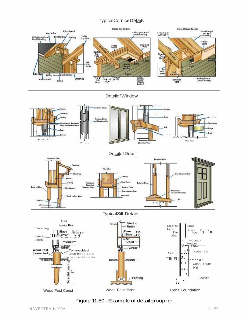
NAVEDTRA 14069A 11-52
.
TypicalCornice Details
Detai lof Window
Friat8ll:.'d nd Molllh9
•• ...........
-'-'-'-'"+
........
p, ..,,._
Detai lof Door
TypicalSill Details
Sheathirtg
Stud
Interior Fin.
Fin ffr Sub Fir
Exterior
Finish Sole
Stud
Base Fin. Flr. hoe S . Fir.
Exterior·__JIJ==;;;;;,i,±;;;;f Finish
Plat
- Joiat
Header Girder :'J •• Plate
Termite shie d used n tropic and
G.L ;..·..•.· Ancho..- Bolt
,.,,.....s,ermi-tropic clima tes "'llilRj ••• i,.....,,. • • Cone. Found.
..•. •• •
•
•.
Wall
Footin·;r
Wood Post Const Wood Foundation Cone.Foundation
Figure 11-50 - Example of detaiIgrouping.
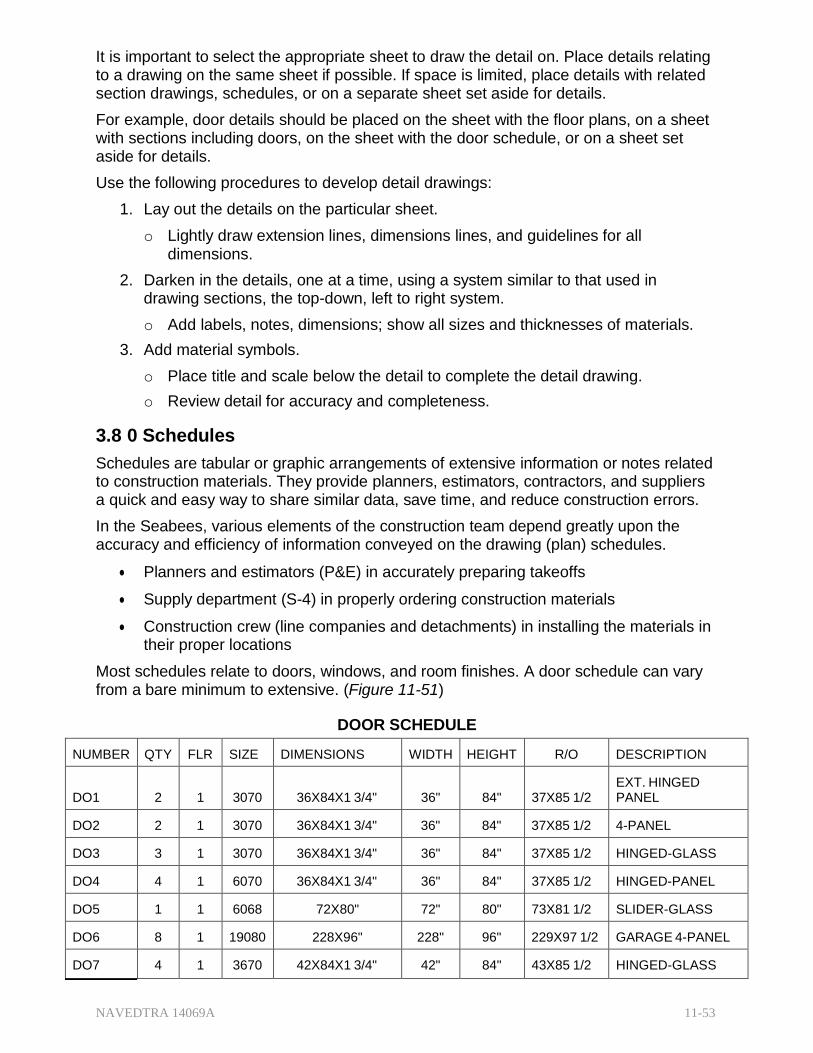
NAVEDTRA 14069A 11-53
It is important to select the appropriate sheet to draw the detail on. Place details relating to a drawing on the same sheet if possible. If space is limited, place details with related section drawings, schedules, or on a separate sheet set aside for details.
For example, door details should be placed on the sheet with the floor plans, on a sheet with sections including doors, on the sheet with the door schedule, or on a sheet set aside for details.
Use the following procedures to develop detail drawings:
1. Lay out the details on the particular sheet.
o Lightly draw extension lines, dimensions lines, and guidelines for all dimensions.
2. Darken in the details, one at a time, using a system similar to that used in drawing sections, the top-down, left to right system.
o Add labels, notes, dimensions; show all sizes and thicknesses of materials.
3. Add material symbols.
o Place title and scale below the detail to complete the detail drawing.
o Review detail for accuracy and completeness.
3.8 0 Schedules
Schedules are tabular or graphic arrangements of extensive information or notes related to construction materials. They provide planners, estimators, contractors, and suppliers a quick and easy way to share similar data, save time, and reduce construction errors.
In the Seabees, various elements of the construction team depend greatly upon the accuracy and efficiency of information conveyed on the drawing (plan) schedules.
Planners and estimators (P&E) in accurately preparing takeoffs
Supply department (S-4) in properly ordering construction materials
Construction crew (line companies and detachments) in installing the materials in their proper locations
Most schedules relate to doors, windows, and room finishes. A door schedule can vary from a bare minimum to extensive. (Figure 11-51)
DOOR SCHEDULE
NUMBER QTY FLR SIZE DIMENSIONS WIDTH HEIGHT R/O DESCRIPTION
DO1
2
1
3070
36X84X1 3/4"
36"
84"
37X85 1/2
EXT. HINGED PANEL
DO2 2 1 3070 36X84X1 3/4" 36" 84" 37X85 1/2 4-PANEL
DO3 3 1 3070 36X84X1 3/4" 36" 84" 37X85 1/2 HINGED-GLASS
DO4 4 1 6070 36X84X1 3/4" 36" 84" 37X85 1/2 HINGED-PANEL
DO5 1 1 6068 72X80" 72" 80" 73X81 1/2 SLIDER-GLASS
DO6 8 1 19080 228X96" 228" 96" 229X97 1/2 GARAGE 4-PANEL
DO7 4 1 3670 42X84X1 3/4" 42" 84" 43X85 1/2 HINGED-GLASS

NAVEDTRA 14069A 11-54
Figure 11-51 – Example of a door schedule.
A door schedule may include door number, quantity, mark or code number, type, size, material description, lintel, and remarks.
Doors are commonly marked with a number or numbers and letters; the letter "D" is a common designation used for doors (sometimes enclosed in a circle or other shape).
A window schedule (Figure 11-52) provides an organized presentation of the significant window characteristics. Information often includes mark, window type, size, required opening size, material type, lintels, and remarks.
WINDOW SCHEDULE
NUMBER QTY FLR SIZE DIMENSIONS WIDTH HEIGHT R/O DESCRIPTION
WO1
2
3
3036
36X42"
36"
42"
37X43 1/2
SNGL CASEMENT
WO2
4
3
4050
48X60"
48"
60"
49X61 1/2
SNGL CASEMENT
WO3 3 2 3052 36X62" 36" 62" 37X63 1/2 FIXED GLASS
WO4 4 2 2014 24X16" 24" 16" 25X17 1/2 FIXED GLASS
WO5 1 3 1070 12X84" 12" 84" 13X85 1/2 FIXED GLASS
WO6 3 1 7040 84X48" 84" 48" 85X491/2 FIXED GLASS
WO7 4 1 80174 96X207 1/2" 96" 208" 97X209 MULLED UNIT
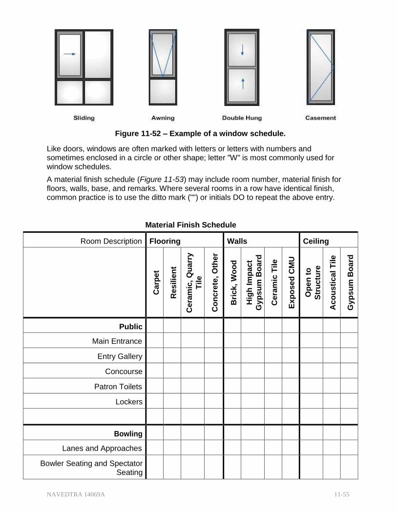
NAVEDTRA 14069A 11-55
Figure 11-52 – Example of a window schedule.
Like doors, windows are often marked with letters or letters with numbers and sometimes enclosed in a circle or other shape; letter "W" is most commonly used for window schedules.
A material finish schedule (Figure 11-53) may include room number, material finish for floors, walls, base, and remarks. Where several rooms in a row have identical finish, common practice is to use the ditto mark ("") or initials DO to repeat the above entry.
Material Finish Schedule
Room Description Flooring Walls Ceiling
Carp
et
Res
ilie
nt
Cera
mic
, Q
ua
rry
Tile
Co
nc
rete
, O
ther
Bri
ck,
Wo
od
Hig
h Im
pac
t
Gy
psu
m B
oa
rd
Cera
mic
Tile
Ex
po
se
d C
MU
Op
en
to
Str
uctu
re
Aco
us
tica
l T
ile
Gy
psu
m B
oa
rd
Public
Main Entrance
Entry Gallery
Concourse
Patron Toilets
Lockers
Bowling
Lanes and Approaches
Bowler Seating and Spectator Seating

NAVEDTRA 14069A 11-56
Mechanics
Pinsetters/Service Aisle
Mechanic's Workroom
Mechanic's Toilet
Laundry
Storage
Figure 11-53 – Example of a material finish schedule.
Take great care when making a change in the material finish for a particular room. Such changes may greatly affect other rooms below it in the schedule. Errors are less likely to occur and revisions will be easier to handle if you letter each space in the schedule individually. Remember; whenever possible place all of the schedules on the same sheet as their respective drawings on the building.
3.9.0 Bill of Materials
A bill of materials (BM) is a tabular statement of material requirements for a given project. It contains information, such as stock numbers, unit of issue, quantity, line item number, description, vendor, and cost. Sometimes the bill of materials will be submitted on material estimate sheets or material takeoff sheets, but all will contain similar information.
The bill of materials is actually a grouped compilation based on all of the takeoffs and estimates of material needed to complete a structure. The takeoff sheet is usually an actual tally and check of the items shown, noted, or specified on the construction drawings and specifications.
In most cases, each NAVFACENGCOM drawing will contain a separate BM. However, sometimes an in-house project prepared by a local command will contain a BM incorporated within the set of drawings. Figure 11-54 shows an example of a completed Bill of Materials.
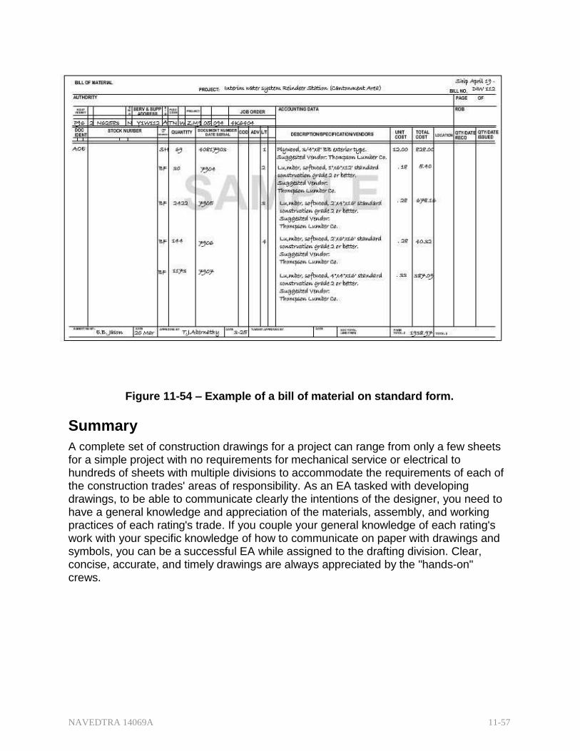
NAVEDTRA 14069A 11-57
Figure 11-54 – Example of a bill of material on standard form.
Summary
A complete set of construction drawings for a project can range from only a few sheets for a simple project with no requirements for mechanical service or electrical to hundreds of sheets with multiple divisions to accommodate the requirements of each of the construction trades' areas of responsibility. As an EA tasked with developing drawings, to be able to communicate clearly the intentions of the designer, you need to have a general knowledge and appreciation of the materials, assembly, and working practices of each rating's trade. If you couple your general knowledge of each rating's work with your specific knowledge of how to communicate on paper with drawings and symbols, you can be a successful EA while assigned to the drafting division. Clear, concise, accurate, and timely drawings are always appreciated by the "hands-on" crews.

NAVEDTRA 14069A 11-58
Review Questions (Select the Correct Response) 1. Which drawings present a proposed building or facility in an attractive
setting?
A. Presentation B. Master Plan C. Preliminary D. Record
2. Which drawings can actually be a schedule or diagram?
A. Red-Lined B. Working C. Shop D. Preliminary
3. Which drawings are commonly used in architectural, topographical, and
construction planning?
A. Final B. Preliminary C. Presentation D. Master Plan
4. Which drawings can be prepared by the construction contractor,
subcontractor, manufacturer, distributor, or supplier?
A. Red-Lined B. Shop C. Preliminary D. Working
5. Which organization(s) maintains and upgrades the master plan on existing
and proposed Navy installations?
A. Naval Facilities Engineering Command (NAVFACENGCOM) B. Regional Engineering Field Division (EFD) C. Local Base Command D. Resident Officer in Charge of Construction (ROICC) and Public
Works Center (PWC)
6. Working drawings are also known as drawings.
A. project B. preliminary C. red-lined D. shop

NAVEDTRA 14069A 11-59
7. What does a complete set of project drawings always contain?
A. An electrical division B. Preliminary Drawings C. As-Builts D. Bill of Materials
8. General drawings are drawn on a relatively small-defined scale, such as
.
A. 1/16 in. = 1 ft or 1/8 in. = 1 ft. B. 1/4 in. = 1 ft or 1/2 in. = 1 ft. C. 1/8 in. = 1 ft or 1/4 in. = 1 ft. D. 1/2 in. = 1 ft or 1 in. = 1 ft.
9. In what projection are most general drawings presented?
A. Elevation B. Cavalier C. Isometric D. Orthographic
10. (True or False) Detail drawings must be presented in the same view as
the general drawing to prevent confusion.
A. True B. False
11. Which drawings provide a check on the accuracy of the design and detail
drawings and often disclose errors?
A. Assembly B. Working C. Final D. Red-Lined
12. (True or False) A bill of materials must always be listed on a separate
sheet.
A. True B. False
13. Except for expeditionary or expedient construction, in a typical military
construction project, will review and evaluate working drawings?
A. Public Works Center (PWC) B. Regional Engineering Field Division (EFD) C. Naval Facilities Engineering Command (NAVFACENGCOM) D. Resident Officer in Charge of Construction (ROICC)

NAVEDTRA 14069A 11-60
14. What organization reviews preliminary drawings if a project is not a Seabee project but will be contracted to other sources?
A. Local ROICC B. Local PWC C. Regional EFD D. NAVFACENGCOM
15. Which drawings become the official contract drawings once the contract is
awarded?
A. Final B. General C. Working D. Master Plan
16. The construction contractor or the military construction force (NMCB) must
provide with as-built drawings indicating any deviations from the contract drawings.
A. PWC B. EFD C. the ROICC D. the base command
17. Conceptual designs in the Navy include both definitive designs and
standard designs for structures and facilities needed on a(n) basis.
A. repetitive B. expeditionary C. emergency D. humanitarian
18. What term describes the detailed working drawings of specialized, unique,
naval facility structures?
A. Facilities Planning B. Facilities Design C. Definitive Designs D. Standard Designs
19. (True or False) Ammunition and explosive design standards may be
modified to accommodate local terrain.
A. True B. False

NAVEDTRA 14069A 11-61
20. What organization assigns new title blocks and drawing numbers when using standard designs for a construction project?
A. EFD B. PWC C. NAVFACENGCOM D. Local command
21. What source provides useful information for Seabee planners such as the
required land area, crew size, man-hours by skill, and the fuel to build a contingency structure?
A. NAVFAC P-34, Engineering and Design Criteria for Navy Facilities B. NAVFAC P-437, Facilities Planning Guide C. NAVFAC P-272, Definitive Designs for Naval Shore Facilities, Part
1 D. NAVFAC P-272, Definitive Designs for Naval Shore Facilities, Part
2
22. What resource provides policy and procedure for preparing and
developing project drawings?
A. NAVFAC P-437, Facilities Planning Guide B. NAVFAC P-34, Engineering and Design Criteria for Navy Facilities C. MIL-HDBK-1006/1 D. NAVFAC P-272, Definitive Designs for Naval Shore Facilities, Part
2
23. What Federal Supply Code for Manufacturers (FSCM) number is required
in the title block of all NAVFACENGCOM drawings?
A. 00891
B. 80091
C. 91008
D. 90081
24. (True or False) If an EFD issued drawing number is no longer being used, it can be reused on a current project.
A. True B. False
25. What resource provides guidance on revising NAVFACENGCON project
drawings?
A. DOD-STD-100 B. MIL-HDBK-1006/1 C. NAVFAC P-437, Facilities Planning Guide D. NAVFAC P-34, Engineering and Design Criteria for Navy Facilities

NAVEDTRA 14069A 11-62
26. What is the minimum allowable height of freehand letters?
A. 5/32 in. B. 3/16 in. C. 1/4 in. D. 5/16 in.
27. As an EA developing drawing for use OUTCONUS, what common linear
unit of measurement should be used?
A. Mils B. Inch C. Millimeter D. As meets the user and geographical area criteria
28. What notes are used either to reflect dimensioning information on the
drawing or to be explanatory?
A. Primary B. Secondary C. Specific D. General
29. What notes refer to all of the notes on the drawing not accompanied by a
leader and an arrowhead?
A. Primary B. Secondary C. Specific D. General
30. When using the conventional horizontal block, general notes must be
placed a minimum of below the revision block space.
A. 2 in. B. 3 in. C. 4 in. D. 5 in.
31. Into what major categories are project drawings divided?
A. Site, architectural, structural, mechanical, electrical, and fire
protection B. Civil, architectural, skeletal, mechanical, power, and fire protection C. Civil, architectural, structural, plumbing, power, and fire protection D. Civil, architectural, structural, mechanical, electrical, and fire
protection

NAVEDTRA 14069A 11-63
32. The drawings allow the Equipment Operators to estimate the amount of any soil displacement (cut and fill) and prepare the site for construction.
A. architectural B. civil C. soil boring log D. delta
33. What type of scale is typically used for site plans on civil drawings?
A. 1/8 = 1 in. B. 1/4 = 1 in. C. Architect's scale D. Engineer's scale
34. What drawings are considered the key drawings in a set of project
drawings?
A. Building sections B. Floor plans C. Elevations D. Details
35. What should be done before placing dimensions on a drawing?
A. Convert them to inches. B. Rescale them. C. Convert them from engineer's scale to architect's scale. D. Lay out and verify them on sketch paper.
36. In concrete and masonry construction, all dimensions are all given to the
of the walls.
A. centerline B. face C. veneer D. lintel
37. (True or False) Elevations are typically drawn at the same scale as the
floor plan.
A. True B. False
38. What drawing should contain all roof, floor, wind, seismic, and other
loads?
A. Civil B. Architectural C. Structural D. Schedule
NAVEDTRA 14069A 11-64
39. What serves as the basis for developing the foundation plan?
A. Architectural drawings B. Civil drawings C. Site plan D. Ground floor plan
40. The floor framing plan is a(n) view of the layout of girders, beams,
and joists.
A. elevation B. plan C. isometric D. cut away
41. (True or False) Roof framing plans for wood frame construction are drawn
in the same manner as the floor framing plan.
A. True B. False
42. What additional drawings are commonly provided for plumbing
(mechanical) plans that are difficult to read?
A. Riser diagrams B. Large scale details C. Sectional cuts D. Orthographic
43. What is the next step in creating an electrical drawing after tracing the
floor plan?
A. Add circuits, circuit numbers, and circuit notations. B. Draw switches. C. Draw convenience outlets. D. Draw the meter and service panel noting voltage rating and
amperage. 44. Sections most commonly apply to the and divisions.
A. architectural, structural B. civil, architectural C. civil, structural D. architectural, mechanical
45. Full building sections are usually located in the division.
A. mechanical B. structural C. architectural D. electrical

NAVEDTRA 14069A 11-65
46. What scale should be used to draw details?
A. 1 in. = 1 ft. B. 11/2 in. = 1 ft. C. 3 in. = 1 ft. D. Large enough to explain required information
47. Most schedules relate to doors, windows, and .
A. room finishes B. concrete pours C. material deliveries D. contract phases
48. (True or False) A bill of material can be submitted on a material estimate
sheet or material takeoff sheet as well as on a bill of material form.
A. True B. False
NAVEDTRA 14069A 11-66
Trade Terms Introduced in This Chapter
Cavalier projections Also called cavalier perspective or high view point; a way to represent a three-dimensional object on a flat drawing, and more specifically, a type of oblique projection.
Isometric projections A form of graphical projection, more specifically, a form of axonometric projection; a method of visually representing three-dimensional objects in two dimensions, in which the three coordinate axes appear equally foreshortened and the angles between any two of them are 120°.
Lintel A horizontal beam used in the construction of buildings and a major architectural contribution of ancient Greece. It usually supports the masonry above a window or door opening. Also know as a header.
Orthographic projections A means of representing a three-dimensional object in two dimensions; with multiview orthographic projections, up to six pictures of an object are produced, with each projection plane parallel to one of the coordinate axes of the object.
Veneer A thin covering of material, such as brick, placed over a backing material of wood frame or block.

NAVEDTRA 14069A 11-67
Additional Resources and References
This chapter is intended to present thorough resources for task training. The following reference works are suggested for further study. This is optional material for continued education rather than for task training.
Blueprint Reading and Sketching, NAVEDTRA 14040, Naval Education and Training Program Management Support Activity*, Pensacola, FL, 2003.
Graphic Symbols for Electrical and Electronics Diagrams, American National Standard, ANSI 2.2-1975, The Institute of Electrical and Electronics Engineers, NY, 1986.

NAVEDTRA 14069A 11-68
CSFE Nonresident Training Course – User Update
CSFE makes every effort to keep their manuals up-to-date and free of technical errors. We appreciate your help in this process. If you have an idea for improving this manual, or if you find an error, a typographical mistake, or an inaccuracy in CSFE manuals, please write or email us, using this form or a photocopy. Be sure to include the exact chapter number, topic, detailed description, and correction, if applicable. Your input will be brought to the attention of the Technical Review Committee. Thank you for your assistance.
Write: CSFE N7A 3502 Goodspeed St. Port Hueneme, CA 93130
FAX: 805/982-5508
E- mail: [email protected]
Rate_ Course Name
Revision Date Chapter Number Page Number(s)
Description
(Optional) Correction
(Optional) Your Name and Address
NAVEDTRA 14069A 12-1
Chapter 12
Surveying: Elements and Equipment
Topics
1.0.0 Classification of Surveying
2.0.0 Types of Surveys
3.0.0 Types of Surveying Operations
4.0.0 Basic Surveying Instruments
5.0.0 Field Equipment
6.0.0 Field Supplies
To hear audio, click on the box.
Overview
This chapter provides an overview of surveying with emphasis on the principles and procedures of basic surveying and the use of various surveying equipment, instruments, and accessories. For you as an EA, accurate surveying is essential because sound decisions in engineering practice depend on the results of your surveys. Surveying is the science of determining the relative positions of points on or near the earth's surface. These points may be needed to locate or lay out roads, airfields, and structures of all kinds. They may be needed for cultural, hydrographic, or terrain features for mapping, and, in the military, these points may be targets for artillery and mortar fire. The relative horizontal positions of these points are determined from distances and directions measured in the field. Their vertical positions are computed from differences in elevation, which are measured directly or indirectly from an established point of reference or datum. The earliest application of surveying was in establishing land boundaries. Although many surveyors still establish or subdivide boundaries of landed properties, the purposes of surveys have branched out to many other areas.
Courts may call upon surveyors to substantiate locations of objects involved in cases, such as major traffic accidents, maritime disasters, or even murder cases, in which direction and distance have a bearing. Surveying continues to play an extremely important role in many branches of engineering. Today, surveys are used to map the earth above and below; for navigational charts used in the air, on land, and at sea, and for certain tasks in geology, forestry, archeology, and landscape architecture. As a surveyor in the Naval Construction Force, you submit survey results before, during, and after planning and construction of advanced base structures, bridges, roads, drainage works, pipelines, and other types of conventional ground systems. In addition, an EA assigned to an oceanographic unit may be involved in hydrography to a great extent, establishing an offshore triangulation network, depth sounding, and mapping. Again, though these surveys are for various purposes, the basic operations are the same- they involve measurements and computations, fieldwork, and office work.

NAVEDTRA 14069A 12-2
Objectives
When you have completed this chapter, you will be able to do the following:
1. Describe the different classifications of surveying.
2. Describe the different types of surveys.
3. Describe the different types of surveying operations.
4. Describe the purpose and uses of basic surveying instruments.
5. Describe the purpose and uses of field equipment.
6. Identify field supplies needed for surveying operations.
Prerequisites
None
This course map shows all of the chapters in Engineering Aid Basic. The suggested training order begins at the bottom and proceeds up. Skill levels increase as you advance on the course map.
Topographic Surveying and Mapping
E
Indirect Leveling/Level and Traverse Computations N
Care and Adjustment of Survey Equipment G
I Materials Testing: Soil and Concrete
N Direct Leveling and Basic Engineering Surveys
E
Horizontal Control E
Direct Linear Measurements and Field Survey Safety R
Surveying: Elements and Equipment I
Construction Drawings N
G Electrical: Systems and Plans
Mechanical: Systems and Plans AID
Concrete and Masonry
Wood and Light Frame Structures B
Drafting: Projections and Sketching A
S Drafting: Geometric Construction
I Drafting: Fundamentals and techniques
C
Drafting: Equipment
Mathematics and Units of Measurement
Engineering Aid Rating

NAVEDTRA 14069A 12-3
Features of this Manual
This manual has several features which make it easy to use online.
Figure and table numbers in the text are italicized. The figure or table is either next to or below the text that refers to it.
The first time a glossary term appears in the text, it is bold and italicized. When your cursor crosses over that word or phrase, a popup box displays with the appropriate definition.
Audio and video clips are included in the text, with an italicized instruction telling you where to click to activate it.
Review questions that apply to a section are listed under the Test Your Knowledge banner at the end of the section. Select the answer you choose. If the answer is correct, you will be taken to the next section heading. If the answer is incorrect, you will be taken to the area in the chapter where the information is for review. When you have completed your review, select anywhere in that area to return to the review question. Try to answer the question again.
Review questions are included at the end of this chapter. Select the answer you choose. If the answer is correct, you will be taken to the next question. If the answer is incorrect, you will be taken to the area in the chapter where the information is for review. When you have completed your review, select anywhere in that area to return to the review question. Try to answer the question again.
NAVEDTRA 14069A 12-4
1.0.0 CLASSIFICATION of SURVEYING
Generally, surveying is divided into two major categories: plane and geodetic surveying.
1.1.0 Plane Surveying
PLANE SURVEYING is a process of surveying in which the portion of the earth being surveyed is considered a plane. The term is used to designate survey work in which the distances or areas involved are small enough that the curvature of the earth can be disregarded without significant error. In general, the term plane surveying applies to surveys of land areas and boundaries (land surveying) in which the areas are of limited extent. For small areas, precise results may be obtained with plane surveying methods, but the accuracy and precision of such results will decrease as the area surveyed increases in size. To make computations in plane surveying, you will use formulas of plane trigonometry, algebra, and analytical geometry. A great number of surveys are of the plane surveying type. Surveys for the location and construction of highways and roads, canals, landing fields, and railroads are classified under plane surveying. Considering that an arc of 10 mile is only 0.04 greater that its subtended chord, that a plane surface tangent to a spherical arc departs only about eight inches at one mile from the point of tangency, and that the sum of the angles of a spherical triangle is only 1 sec greater than the sum of the angles of a plane triangle for an area of approximately 75 square miles on the earth's surface, it is reasonable to consider the errors caused by the earth's curvature only in precise surveys of large areas. In this training manual, we will primarily discuss plane surveying rather than geodetic surveying.
1.2.0 Geodetic Surveying
Geodetic surveying is a process of surveying in which the shape and size of the earth are considered. This type of survey is suited for large areas and long lines and is used to find the precise location of basic points needed for establishing control for other surveys. In geodetic surveys, the stations are normally long distances apart, and this type of surveying requires more precise instruments and surveying methods than does plane surveying. The shape of the earth is thought of as a spheroid, although in a technical sense, it is not really a spheroid. In 1924, the convention of the International Geodetic and Geophysical Union adopted 41,852,960 feet as the diameter of the earth at the equator and 41,711,940 feet as the diameter at its polar axis. The equatorial diameter was computed on the assumption that the flattening of the earth caused by gravitational attraction is exactly 1/297. Therefore, distances measured on or near the surface of the earth are not along straight lines or planes, but on a curved surface. Hence, computation of distances in geodetic surveys make allowances for the earth's minor and major diameters, from which a spheroid of reference is developed. The position of each geodetic station is related to this spheroid. The positions are expressed as latitudes (angles north or south of the Equator) and longitudes (angles east or west of a prime meridian) or as northings and castings on a rectangular grid. The methods used in geodetic surveying are beyond the scope of this training manual.
NAVEDTRA 14069A 12-5
Test your Knowledge (Select the Correct Response)
1. In surveying, the relative horizontal positions of points are determined in relationship to which of the following elements- measured in the field?
A. Only from distances B. Only from directions C. From either distances or directions D. From both distances and directions
2. When is a survey considered to be a geodetic survey?
A. When the earth's curvature must be considered B. When the surface surveyed is water C. When the data from the survey will be used for mapping D. When the survey is either a ground or an aerial survey
2.0.0 TYPES of SURVEYS
Generally, surveys can be classified by their functions. Functionally, surveys are classed as construction, topographic, route, and special. Special surveys, such as photogrammetry, hydrography, and property surveys, are conducted either with special equipment or for a special purpose. Some of the types of surveys that you may perform as an EA are discussed in the following paragraphs.
2.1.1 Construction Surveys
Construction surveys (sometimes called engineering surveys) obtain data essential for planning, estimating, locating, and layout for the various phases of construction activities or projects. This type of survey includes reconnaissance, preliminary, location, and layout surveys.
The objectives of engineering or construction surveying include the following:
1. Obtaining reconnaissance information and preliminary data engineers require for selecting suitable routes and sites and for preparing structural designs
2. Defining selected locations by establishing a system of reference points
3. Guiding construction forces by setting stakes or otherwise marking lines, grades, and principal points and by giving technical assistance
4. Measuring construction items in place for preparing progress reports
5. Dimensioning structures for preparation of as-built plans
All of the above objectives are called engineering surveys by the American Society of Civil Engineers (ASCE), and the term "construction survey" is applied to the last three objectives only. The Army Corps of Engineers, on the other hand, generally applies the term "construction surveying" to all of the objectives listed above. Engineering and/or construction surveys, then, form part of a series of activities leading to the construction of a man-made structure. The term "structure" is usually confined to something, like a building or bridge, built of structural members. It is used here in a broader sense, however, to include all man-made features, such as graded areas; sewer, power, and water lines; roads and highways, and waterfront structures. Construction surveys normally cover areas small enough to use the plane surveying methods and techniques.
NAVEDTRA 14069A 12-6
2.2.1 Topographic Surveys
The purpose of a topographic survey is to gather survey data about the natural and man-made features of land, as well as its elevations. From this information, a three- dimensional map may be prepared. You may prepare the topographic map in the office after collecting the field data or prepare it right away in the field by plane table.
The work usually consists of the following:
1. Establishing horizontal and vertical control that will serve as the framework of the survey
2. Determining enough horizontal location and elevation (usually called side shots) of ground points to provide enough data for plotting when the map is prepared
3. Locating natural and man-made features that may be required by the purpose of the survey
4. Computing distances, angles, and Elevations
5. Drawing the topographic map Topographic surveys are commonly identified with horizontal and/or vertical control of third and lower-order accuracies.
2.3.1 Route Surveys
Route surveys are those conducted for the location and construction of lines of transportation or communication that continue across country for some distance, such as highways, railroads, open-conduit systems, pipelines, and power lines. Generally, the preliminary survey for this work takes the form of a topographic survey.
In the final stage, the work may consist of the following:
1. Locating the center line, usually marked by stakes at 100 feet intervals called stations
2. Determining elevations along and across the center line for plotting profile and cross sections
3. Plotting the profile and cross sections and fixing the grades
4. Computing the volumes of earthwork and preparing a mass diagram
5. Staking out the extremities for cuts and fills
6. Determining drainage areas for ditches and culverts
7. Laying out structures, such as bridges and culverts
8. Locating right-of-way boundaries and staking out fence lines, if necessary
2.4.0 Special Surveys
As mentioned earlier in this chapter, special surveys are conducted for a specific purpose and with special surveying equipment and methods. A brief discussion of some of the special surveys follows.
2.4.1 Surveys
Land Surveys (sometimes called cadastral or property surveys) are conducted to establish the exact location, boundaries, or subdivision of a tract of land in any specified area. This type of survey requires professional registration in all states.
Presently, land surveys generally consist of the following chores:
NAVEDTRA 14069A 12-7
1. Establishing markers or monuments to define and thereby preserve the boundaries of land belonging to a private concern, a corporation, or the government.
2. Relocating markers or monuments legally established by original surveys. This requires examining previous survey records and retracing what was done. When some markers or monuments are missing, they are reestablished following recognized procedures, using whatever information is available.
3. Rerunning old land survey lines to determine their lengths and directions. As a result of the high cost of land, old lines are re-measured to get more precise measurements.
4. Subdividing landed estates into parcels of predetermined sizes and shapes.
5. Calculating areas, distances, and directions and preparing the land map to portray the survey data so that it can be used as a permanent record.
6. Writing a technical description for deeds. 2.4.2 trol Surveys
Control surveys provide "basic control" or horizontal and vertical positions of points to which supplementary surveys are adjusted. These types of surveys (sometimes termed geodetic surveys) are conducted to provide geographic positions and plane coordinates of triangulation/ traverse stations and the elevations of bench marks. These control points are further used as references for hydrographic surveys of coastal waters, for topographic control, and for the control of many state, city, and private surveys. Horizontal and vertical controls generated by land (geodetic) surveys provide coordinated position data for all surveyors. Therefore, these types of surveys must use first-order and second-order accuracies.
2.4.3 Hydrographic Surveys
Hydrographic surveys are made to acquire data required to chart and/or map shorelines and bottom depths of streams, rivers, lakes, reservoirs, and other larger bodies of water. This type of survey is also important for navigation and the developing water resources for flood control, irrigation, electrical power, and water supply. LIke other special surveys, hydrographic surveys make use of several types of electronic and radio-acoustical instruments. These special devices are commonly used to determine water depths and the location of objects on the bottom by a method called taking soundings. A surveyor takes soundings by measuring the time required for sound to travel downward and reflect back to a receiver aboard a vessel.
Test your Knowledge (Select the Correct Response)
3. Reestablishing an old property boundary from missing requires what kind of survey?
A. Topographic B. Construction C. Route D. Land
NAVEDTRA 14069A 12-8
4. Gathering information needed to prepare as-built drawings for a completed project requires what kind of survey?
A. Topographic B. Construction C. Route D. Land
5. Gathering data about the natural and man-made features of the land requires
what kind of survey?
A. Topographic B. Construction C. Route D. Land
3.0.0 TYPES of SURVEYING OPERATIONS
The practice of surveying actually boils down to fieldwork and office work. Field work consists of taking measurements, collecting engineering data, and testing materials. Office work includes computation and drawing the necessary information for the purpose of the survey.
3.1.0 Fieldwork
Field work is of primary importance in all types of surveys. To be a skilled surveyor, you must spend a certain amount of time in the field to acquire needed experience. This training manual will help you understand the theory behind surveying, instruments and their uses, and surveying methods. However, proficiency in actual surveying, as in other professions, depends largely upon the duration, extent, and variety of experience. Develop the habit of studying a problem thoroughly before going into the field. Know exactly what is to be done, how to do it, and the instruments and materials necessary to do it. Developing speed and consistent accuracy in all your fieldwork is essential. This means that you will need practice in handling the instruments, taking observations, keeping field notes, and planning systematic moves. Do not accept any measurement as correct without verification. Whenever possible, verify using a method different than that used in the original measurement. Ensure that the precision of your measurements are consistent with the accepted standard for the survey. Fieldwork also includes adjusting the instruments and caring for field equipment. Do not attempt to adjust any instrument unless you understand the workings or functions of its parts. Instrument adjustments in the early stages of your career require close supervision from a senior EA.
3.1.1 Engineering Data
Collecting engineering data is part of Seabee surveying. Engineering data is any information essential for efficient construction. Most of your fieldwork, such as running a traverse, leveling, and determining cuts and fills, may be classified under this category. However, compiling these field measurements and converting them into a common medium of value to the engineer requires skill you can only attain through experience. Although all planning and organization is generally handled by the engineering officer or by a senior EA, the actual collection of engineering data will generally be delegated to

NAVEDTRA 14069A 12-9
you; hence, it is to your advantage to understand the procedures early on. This job may require combination of fieldwork and office work. If information of the same quality can be found in sources other than actual fieldwork, do not hesitate to use them. If necessary, use spot checks to verify certain points, depending on the source.
Each project requires the study of a different set of engineering data, so the engineering officer or the senior EAs must devise a workable method of compilation for each particular project. The compiled data must be complete in all respects required by the project and the compilation completed with sufficient lead time. Generally, a separate folder for each project is maintained and labeled. Some of the engineering data that may be considered for Seabee projects are as follows:
Vicinity maps, topographic maps, or aerial photographs of the site
Geographic factors such as accessibility and real estate
Geographic location: both latitude/longitude and control points (horizontal/vertical)
Tide information
Weather and climatic conditions: rainfall, wind velocity (including direction and duration), flood, and seasons that have a reputation for extreme weather
Current velocity and discharge of a rivers/streams and estimates of the watershed area, if available
Types of soils and their natural conditions (collect samples for testing)
Availability of construction materials, such as rocks, gravel, sand, borrow pits, and timber near the site
Availability and suitability of local labor and existing facilities, such as sources of power, water, and other utilities
Other factors affecting construction, military operations, and logistics support
3.1.2 Factors Affecting Fieldwork
The surveyor must constantly be alert to the different conditions encountered in the field. Physical factors, such as terrain and weather conditions, affect each field survey to varying degrees. Fog or mist can limit the ability to take telescope measurements. Swamps and flood plains under high water can impede taping surveys. Sights over open water or fields of flat, unbroken terrain create ambiguities in measurements taken with microwave equipment. The lengths of light-wave distance in measurements are reduced in bright sunlight. Generally, reconnaissance will predetermine the conditions and alert the survey party to the best methods and the rate of progress to expect.
Technical readiness is another factor affecting fieldwork. As you gain experience in handling various surveying instruments, you can shorten survey time and avoid errors that would require resurvey.
The purpose and type of survey are primary factors determining accuracy requirements. First-order triangulation, which becomes the basis or "control" of future surveys, is made to high-accuracy standards. Cuts and fills for a highway survey, on the other hand, have much lower accuracy standards. Some construction surveys require computing normally inaccessible distances. Compute the distance by means of trigonometry, using the angles and the one distance that can be measured. You must make the measurements to a high degree of precision to maintain accuracy in the computed distance. In simple
NAVEDTRA 14069A 12-10
terms, the purpose of the survey determines the accuracy requirements. The required accuracy, in turn, influences the selection of instruments and procedures. For instance, comparatively rough procedures can be used in measuring for earthmoving, but grade and alignment of a highway have to be much more precise. Each increase in precision also increases the time required to make the measurement, since you must take greater care and more observations.
There is always a slight degree of error in survey measurements. No measurement is ever exact. The errors can be systematic or accidental and are explained later in the chapter. Survey measurements are also subject to mistakes. These occur most commonly from misunderstanding of the problem, poor judgment, confusion on the part of the surveyor, or simple oversight. By working out a systematic procedure, the surveyor will often detect a mistake when an operation seems out of place. That procedure will be an advantage in setting up the equipment, making observations, recording field notes, and making computations.
Survey speed is not the result of hurrying; it is the result of saving time through the following factors:
1. The skill of the surveyor in handling the Instruments
2. Intelligent planning and preparation of the work
3. Making only those measurements that are consistent with the accuracy requirements
Experience is of great value, but in the final analysis, it is the exercise of common sense that makes the difference between a good surveyor and an exceptional surveyor.
3.1.3 Field Survey Parties
The size of a field survey party depends upon the survey requirements, the equipment available, the method of survey, and the number of personnel needed to perform the tasks required. The Seabees commonly use three types of field survey parties: level party, transit party, and stadia party.
3.1.3.1 Level Party
The smallest leveling party consists of two people: an instrumentman and a rodman. In this type of organization, the instrumentman acts as note keeper. The party may need another recorder and one or more extra rodmen to improve the efficiency of the leveling operations. Having additional rodmen eliminates the waiting periods while one person moves from point to point, and an additional recorder allows the instrumentman to take readings as soon as the rodmen are in position. When leveling operations take place alongside other control surveys, the leveling party may become part of a combined party with personnel assuming dual duties, as the workload requires or the party chief directs.
3.1.3.2 Transit Party
A transit party consists of at least three people: an instrumentman, a head chainman, and a party chief. The party chief is usually the note keeper and may double as rear chainman, or there may be an additional rear chainman. The instrumentman operates the transit; the head chainman measures the horizontal distances; and the party chief directs the survey and keeps the notes.
NAVEDTRA 14069A 12-11
3.1.3.3 S ta d ia P a rty
A stadia party consists of at least three people: an instrumentman, a note keeper, and a rodman. However, if the distance between the points is great, the party should include a second rodman so that one can proceed to a new point while the other holds the rod on the point being observed. The note keeper records the data called off by the instrumentman and makes the sketches required.
3.1.4 Field Notes
Field notes are the only record left after the field survey party departs the survey site. If these notes are not clear and complete, the field survey is of little value. It is therefore necessary that your field notes contain a complete record of all of the measurements made during the survey and that they include, where necessary, sketches and narrations to clarify the notes. The following guidelines apply.
3.1.4.1 Lettering
All field notes should be lettered legibly. The lettering should be freehand vertical or slanted Gothic style, as illustrated in basic drafting. A fairly hard pencil or a mechanical lead holder with a 3H or 4H lead is recommended.
3.1.4.2 Format
Notes must be made in the regular field notebook and not on scraps of paper for later transcription. Record separate surveys on separate pages or in different books. Mark the front cover of the field notebook with the name of the project, its general location, the types of measurements recorded, the designation of the survey unit, and other pertinent information.
The inside front cover should contain instructions for the return of the notebook, if lost. Reserve the right-hand pages as an index of the field notes, a list of party personnel and their duties, a list of the instruments used, dates and reasons for any instrument changes during the course of the survey, and a sketch and description of the project.
Throughout the remainder of the notebook, clearly indicate the beginning and ending of each day's work. Where pertinent, also record the weather, including temperature and wind velocities. To minimize recording errors, someone other than the recorder should check and initial all data entered in the notebook.
3.1.4.3 Recording
Field note recording takes three general forms: tabulation, sketches, and descriptions. Any or all of these forms may be combined, when necessary, to make a complete record.
In tabulation, the numerical measurements are recorded in columns according to a prescribed plan. Spaces are also reserved to permit necessary computations.
Sketches add much to clarify field notes; use them liberally when applicable. You may draw them to an approximate scale or exaggerate important details for clarity. A small ruler or triangle can aid in making sketches. Add measurements directly on the sketch or keyed in some way to the tabular data. An important requirement of a sketch is legibility. See that the sketch is drawn clearly and is large enough to easily understand.
Tabulation, with or without added sketches, can also be supplemented with descriptions. The description may be only one or two words to clarify the recorded
NAVEDTRA 14069A 12-12
measurements, or it may be a lengthy narrative if it is to be used at some future time to locate a survey monument.
Erasures are not permitted in field notebooks. Line out individual numbers or lines recorded incorrectly and insert the correct values. Neatly cross out pages to be rejected and reference them to their substitutes. This procedure is mandatory since the field notebook is the book of record and is often used as legal evidence. Use standard abbreviations, signs, and symbols in field notebooks. If there is any doubt as to their meaning, give an explanation in the form of notes or legends.
3.2.0 Office Work
Office work in surveying consists of converting the field measurements into a usable format. The conversion of computed, often mathematical, values may be required immediately to continue the work, or it may be delayed until completion of a series of field measurements. Although these operations are performed in the field during lapses between measurements, they can also be considered office work. Such operations are normally done to save time. Special equipment, such as calculators, conversion tables, and some drafting equipment, are used in most office work. In office work, converting field measurements (also called reducing) involves computing, adjusting, and applying a standard rule to numerical values.
3.2.1 tation
In any field survey operation, measurements are derived by the application of some form of mathematical computation. It may be simple addition of several full lengths and a partial tape length to record a total linear distance between two points. It may be adding or subtracting differences in elevation to determine the height of instrument or the elevation during leveling. Then again, it may be checking angles to ensure that the allowable error is not exceeded. Office computing converts these distances, elevations, and angles into a more usable form. The finished measurements may end up as a computed volume of dirt to be moved for a highway cut or fill, an area of land needed for a Seabee construction project, or a new position of a point from which other measurements can be made. In general, office computing reduces the field notes to either a tabular or graphic form for a permanent record or for continuation of fieldwork.
3.2.2 Adjustment
Some survey processes are not complete until measurements are within usable limits or the measurements have been corrected to distribute accumulated errors. Small errors that are not apparent in individual measurements can accumulate to a sizeable amount. Adjusting is the process of distributing these errors over many points or stations until the effect on each point is reduced enough to put all measurements within usable limits.
For example, assume that 100 measurements were made to the nearest unit for the accuracy required. This requires estimating the nearest one-half unit during measurement. At the end of the course, an error of + 4 units results. Adjusting this means each measurement is reduced 0.04 unit. Since the measurements were read only to the nearest unit, this adjustment would not be measurable at any point, and the adjusted result would be correct.
3.2.2.1 Significant Figures
Significant figures are those digits in a number that have meaning; that is, those values that are known to be exact. In a measured quantity, the accuracy of the measurement
NAVEDTRA 14069A 12-13
determines the number of significant figures. For example, a roughly measured distance of 193 feet has three significant figures. More carefully measured, the same distance, 192.7 feet, has four significant figures. If measured still more accurately, 192.68 feet has five significant figures.
In surveying, the significant figures should reflect the allowable error, or tolerance, in the measurements. For example, suppose a measurement of 941.26 units is made with a probable error of ± 0.03 unit. The ± 0.03 casts some doubt on the fifth digit which can vary from 3 to 9, but the fourth digit will still remain 2. We can say that 941.26 has five significant figures; and from the allowable error, we know the fifth digit is doubtful. However, if the probable error were ±0.07, the fourth digit could be affected. The number could vary from 941.19 to 941.33, and the fourth digit could be read 1, 2, or 3. The fifth digit in this measurement is meaningless. The number has only four significant figures and should be written as such.
The number of significant figures in a number ending in one or more zeros is unknown unless more information is given. The zeros may have been added to show the location of the decimal point; for example, 73200 may have three, four, or five significant figures, depending on whether the true value is accurate to 100, 10, or 1 unit(s). If the number is written 73200.0, accuracy is carried to the tenth of a unit and indicates six significant figures.
When decimals are used, the number of significant figures is not always the number of digits. A zero may or may not be significant, depending on its position with respect to the decimal and the digits. As mentioned above, zeros may have been added to show the position of the decimal point. Study the following examples:
0.000047 . . . . . . . two significant figures
0.0100470 . . . . . . . six significant figures
0.1000470 . . . . . . . seven significant figures
2.0100470 . . . . . . . eight significant figures
In long computations, carry out the values to one more digit than the result requires. Round off the number to the required number of digits as a final step.
3.2.2.2 2.2 Rounding Off Numbers
Rounding off is the process of dropping one or more digits and replacing them with zeros, if necessary, to indicate the number of significant figures.
Numbers used in surveying are rounded off according to the following rules:
o When the digit to be dropped is less than five, the number is written without the digit or any others that follow it. (Example: 0.054 becomes 0.05.)
o When the digit is equal to five, the nearest even number is substituted for the preceding digit. (Examples: 0.055 becomes 0.06; 0.045 becomes 0.04.)
o When the digit to be dropped is greater than five, the preceding digit is increased by one. (Example: 0.047 becomes 0.05.)
o Dropped digits to the left of the decimal point are replaced by zeros.
o Dropped digits to the right of the decimal points are never replaced.
NAVEDTRA 14069A 12-14
3.2.2.3 2.3 Checking Computations
Most mathematical problems can be solved by more than one method. To check a set of computations, use a method that differs from the original method, if possible. An inverse solution, starting with the computed value and solving for the field data, is one possibility. You can also use the planimeter and the protractor for approximate checking. Use a graphical solution when feasible, especially if it takes less time than a mathematical or logarithmic solution. Always recompute each step that cannot be checked by any other method, and, if possible, another EA should recompute the problem. When an error or mistake is found, the computation should be rechecked before the correction is accepted.
3.2.3 in Surveying
Except for some freehand sketches, drafting in surveying is generally performed by mechanical means; for example lines and surveying symbols are generally drawn with the aid of a straightedge, spline, template, etcetera. The drawings directly related to surveying are maps, profiles, cross sections, mass diagrams, and, to some extent, other graphical calculations. Their usefulness depends upon how accurately you plot the points and lines representing the field measurements. You must adhere to the requirements of standard drawing practices.
When drawing a property map, include the following general information:
The length of each line, either indicated on the line itself or in a tabulated form, with the distances keyed to the line designation
The bearing of each line or the angles between lines
The location of the mapped area as referenced to an established coordinate system
The location and kind of each established monument indicating distances from reference marks
The name of each road, stream, landmark, etcetera
The names of all property owners, including those whose lots are adjacent to the mapped area.
The direction of the true and/or magnetic meridian
A graphical scale showing the corresponding numerical equivalent
A legend to the symbols shown on the map, if those shown are not standard signs
A title block that distinctly identifies the tract mapped or the owner's name (It is required to contain the name of the surveyor, the name of the draftsman, and the date of the survey)
Besides the above information, some other items may be required for the map to become a public record. When this is the case, consult the local office of the Bureau of Land Management or the local surveyors' society for the correct general information requirements to be included in the map to be drawn.
In drawing maps that will be used as a basis for studies, such as those to be used in roads, structures, or waterfront construction, you are required to include the following general information:
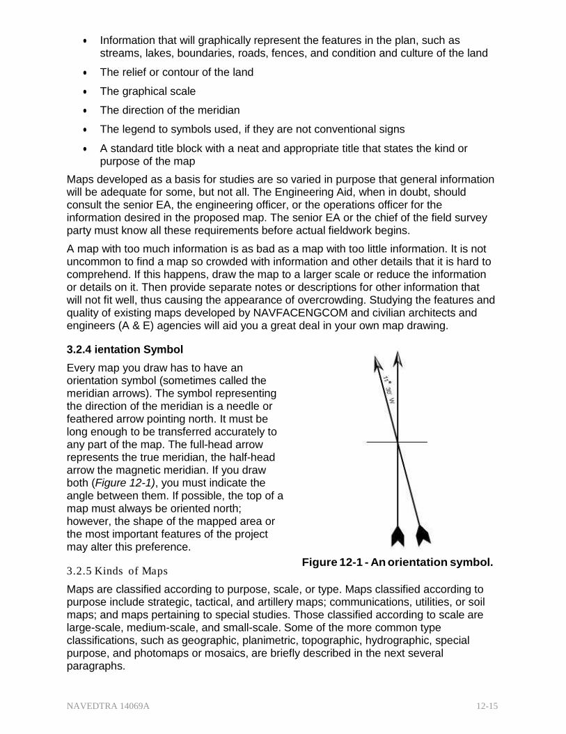
NAVEDTRA 14069A 12-15
Information that will graphically represent the features in the plan, such as streams, lakes, boundaries, roads, fences, and condition and culture of the land
The relief or contour of the land
The graphical scale
The direction of the meridian
The legend to symbols used, if they are not conventional signs
A standard title block with a neat and appropriate title that states the kind or purpose of the map
Maps developed as a basis for studies are so varied in purpose that general information will be adequate for some, but not all. The Engineering Aid, when in doubt, should consult the senior EA, the engineering officer, or the operations officer for the information desired in the proposed map. The senior EA or the chief of the field survey party must know all these requirements before actual fieldwork begins.
A map with too much information is as bad as a map with too little information. It is not uncommon to find a map so crowded with information and other details that it is hard to comprehend. If this happens, draw the map to a larger scale or reduce the information or details on it. Then provide separate notes or descriptions for other information that will not fit well, thus causing the appearance of overcrowding. Studying the features and quality of existing maps developed by NAVFACENGCOM and civilian architects and engineers (A & E) agencies will aid you a great deal in your own map drawing.
3.2.4 ientation Symbol
Every map you draw has to have an orientation symbol (sometimes called the meridian arrows). The symbol representing the direction of the meridian is a needle or feathered arrow pointing north. It must be long enough to be transferred accurately to any part of the map. The full-head arrow represents the true meridian, the half-head arrow the magnetic meridian. If you draw both (Figure 12-1), you must indicate the angle between them. If possible, the top of a map must always be oriented north; however, the shape of the mapped area or the most important features of the project may alter this preference.
3.2.5 Kinds of Ma ps
Figure 12-1 - An orientation symbol.
Maps are classified according to purpose, scale, or type. Maps classified according to purpose include strategic, tactical, and artillery maps; communications, utilities, or soil maps; and maps pertaining to special studies. Those classified according to scale are large-scale, medium-scale, and small-scale. Some of the more common type classifications, such as geographic, planimetric, topographic, hydrographic, special purpose, and photomaps or mosaics, are briefly described in the next several paragraphs.
NAVEDTRA 14069A 12-16
3.2.5.1 Geographic Maps
A geographic map is a map of a large area, such as a state or country, that shows the location of towns, counties, cities, rivers or streams, lakes, roads, and principal civil boundaries, such as county and state lines. Maps showing the general location of human works, such as the Railroad Map of the United States, the Irrigation Map of Arizona, and the Panama Canal Zone Map, are also classified as geographical maps.
3.2.5.2 Planimetric Maps
These maps show natural or man-made features in a horizontal plane only. They omit relief in any measurable form. A few examples of planimetric maps are property, city layout, site plan, communications, route and distance, and isogonic maps of the magnetic variation lines.
3.2.5.3 5.3 Topographic Maps
Maps that depict the natural and man-made features of the earth's surface in a measurable form, showing both horizontal and vertical positions are called topographical maps. Vertical positions, or relief, are normally represented by contours. A precise topographic map shows surface features so perfectly that it can be used for making an exact three-dimensional model of the area. Such a model is called a relief map. Seabees mostly work with heavy construction related topographic maps.
3.2.5.4 Hydrographic Maps
A hydrographic map shows the shorelines, location and depth of soundings, and often the topographic and other features of lands adjacent to the shorelines. It also shows the locations of both horizontal and vertical control in the area.
3.2.5.5 Special-Purpose Maps
These are maps developed for specific purposes. A preliminary map developed from a preliminary survey of a highway, a location map showing the alignment of the located line, and a right-of-way map showing the boundaries of the right-of-way and the adjacent lands all come under the heading of special purpose maps.
3.2.5.6 Mosaic and Overlays
The aerial photographic mosaic is constructed from two or more overlapping prints joined so that they form a single picture. Usually, vertical photographs are used to obtain a map-like result; however, oblique photographs may be used, in which case the result is a panorama. The mosaic has become increasingly useful in cartography and related fields since World War I. It can represent large geographic areas with each feature of terrain assuming its natural appearance and approximating its proportionate size. The U.S. Army Topographic Command has developed from mosaics a multi- colored map of the entire United States and maps of other countries. The Army calls it a pictomap; this is the type of map that is generally used in a war zone.
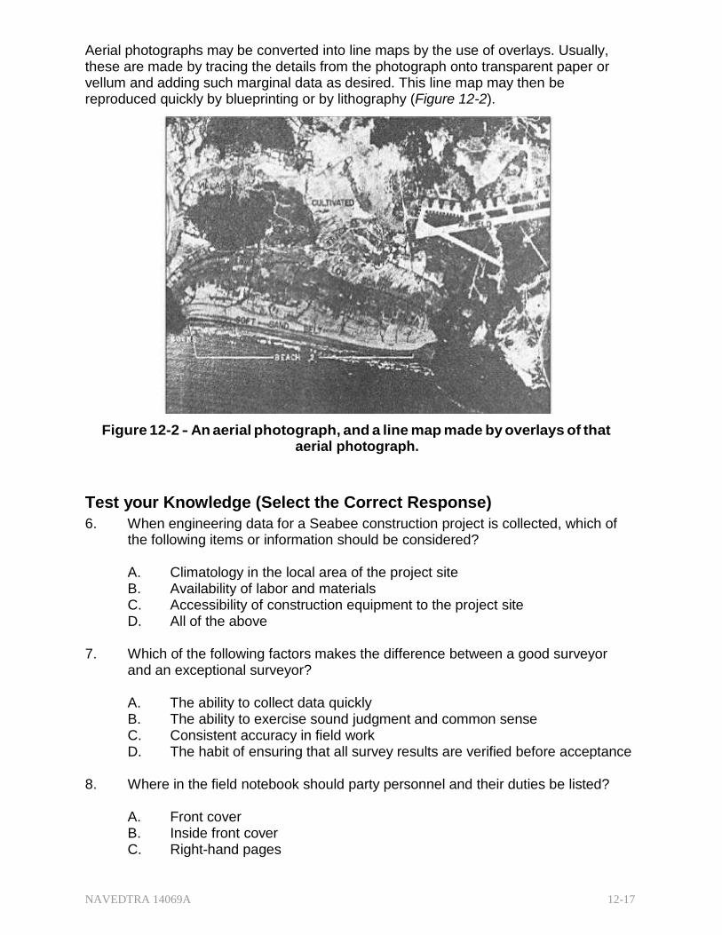
NAVEDTRA 14069A 12-17
Aerial photographs may be converted into line maps by the use of overlays. Usually, these are made by tracing the details from the photograph onto transparent paper or vellum and adding such marginal data as desired. This line map may then be reproduced quickly by blueprinting or by lithography (Figure 12-2).
Figure 12-2 - An aerial photograph, and a line map made by overlays of that aerial photograph.
Test your Knowledge (Select the Correct Response)
6. When engineering data for a Seabee construction project is collected, which of the following items or information should be considered?
A. Climatology in the local area of the project site B. Availability of labor and materials C. Accessibility of construction equipment to the project site D. All of the above
7. Which of the following factors makes the difference between a good surveyor
and an exceptional surveyor?
A. The ability to collect data quickly B. The ability to exercise sound judgment and common sense C. Consistent accuracy in field work D. The habit of ensuring that all survey results are verified before acceptance
8. Where in the field notebook should party personnel and their duties be listed?
A. Front cover B. Inside front cover C. Right-hand pages
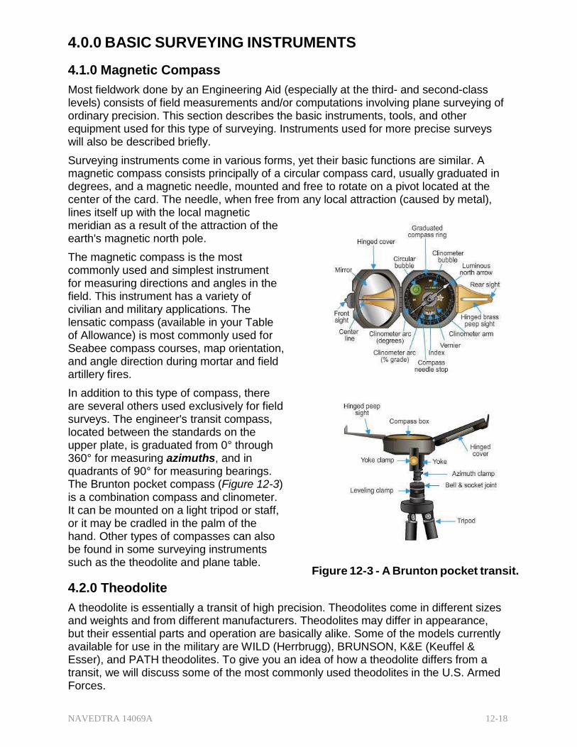
NAVEDTRA 14069A 12-18
4.0.0 BASIC SURVEYING INSTRUMENTS
4.1.0 Magnetic Compass
Most fieldwork done by an Engineering Aid (especially at the third- and second-class levels) consists of field measurements and/or computations involving plane surveying of ordinary precision. This section describes the basic instruments, tools, and other equipment used for this type of surveying. Instruments used for more precise surveys will also be described briefly.
Surveying instruments come in various forms, yet their basic functions are similar. A magnetic compass consists principally of a circular compass card, usually graduated in degrees, and a magnetic needle, mounted and free to rotate on a pivot located at the center of the card. The needle, when free from any local attraction (caused by metal), lines itself up with the local magnetic meridian as a result of the attraction of the earth's magnetic north pole.
The magnetic compass is the most commonly used and simplest instrument for measuring directions and angles in the field. This instrument has a variety of civilian and military applications. The lensatic compass (available in your Table of Allowance) is most commonly used for Seabee compass courses, map orientation, and angle direction during mortar and field artillery fires.
In addition to this type of compass, there are several others used exclusively for field surveys. The engineer's transit compass, located between the standards on the upper plate, is graduated from 0° through 360° for measuring azimuths, and in quadrants of 90° for measuring bearings. The Brunton pocket compass (Figure 12-3) is a combination compass and clinometer. It can be mounted on a light tripod or staff, or it may be cradled in the palm of the hand. Other types of compasses can also be found in some surveying instruments such as the theodolite and plane table.
4.2.0 Theodolite
Figure 12-3 - A Brunton pocket transit.
A theodolite is essentially a transit of high precision. Theodolites come in different sizes and weights and from different manufacturers. Theodolites may differ in appearance, but their essential parts and operation are basically alike. Some of the models currently available for use in the military are WILD (Herrbrugg), BRUNSON, K&E (Keuffel & Esser), and PATH theodolites. To give you an idea of how a theodolite differs from a transit, we will discuss some of the most commonly used theodolites in the U.S. Armed Forces.
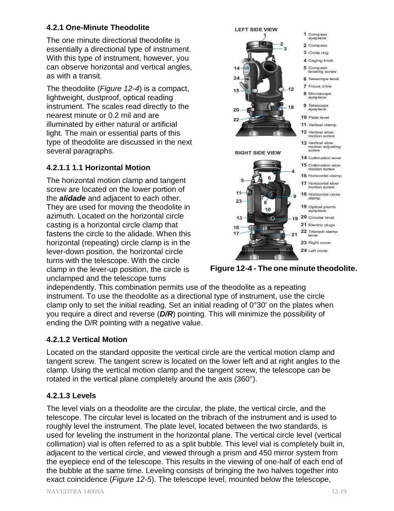
NAVEDTRA 14069A 12-19
4.2.1 One-Minute Theodolite
The one minute directional theodolite is essentially a directional type of instrument. With this type of instrument, however, you can observe horizontal and vertical angles, as with a transit.
The theodolite (Figure 12-4) is a compact, lightweight, dustproof, optical reading instrument. The scales read directly to the nearest minute or 0.2 mil and are illuminated by either natural or artificial light. The main or essential parts of this type of theodolite are discussed in the next several paragraphs.
4.2.1.1 1.1 Horizontal Motion
The horizontal motion clamp and tangent screw are located on the lower portion of the alidade and adjacent to each other. They are used for moving the theodolite in azimuth. Located on the horizontal circle casting is a horizontal circle clamp that fastens the circle to the alidade. When this horizontal (repeating) circle clamp is in the lever-down position, the horizontal circle turns with the telescope. With the circle clamp in the lever-up position, the circle is unclamped and the telescope turns
Figure 12-4 - The one minute theodolite.
independently. This combination permits use of the theodolite as a repeating instrument. To use the theodolite as a directional type of instrument, use the circle clamp only to set the initial reading. Set an initial reading of 0°30' on the plates when you require a direct and reverse (D/R) pointing. This will minimize the possibility of ending the D/R pointing with a negative value.
4.2.1.2 Vertical Motion
Located on the standard opposite the vertical circle are the vertical motion clamp and tangent screw. The tangent screw is located on the lower left and at right angles to the clamp. Using the vertical motion clamp and the tangent screw, the telescope can be rotated in the vertical plane completely around the axis (360°).
4.2.1.3 Levels
The level vials on a theodolite are the circular, the plate, the vertical circle, and the telescope. The circular level is located on the tribrach of the instrument and is used to roughly level the instrument. The plate level, located between the two standards, is used for leveling the instrument in the horizontal plane. The vertical circle level (vertical collimation) vial is often referred to as a split bubble. This level vial is completely built in, adjacent to the vertical circle, and viewed through a prism and 450 mirror system from the eyepiece end of the telescope. This results in the viewing of one-half of each end of the bubble at the same time. Leveling consists of bringing the two halves together into exact coincidence (Figure 12-5). The telescope level, mounted below the telescope,
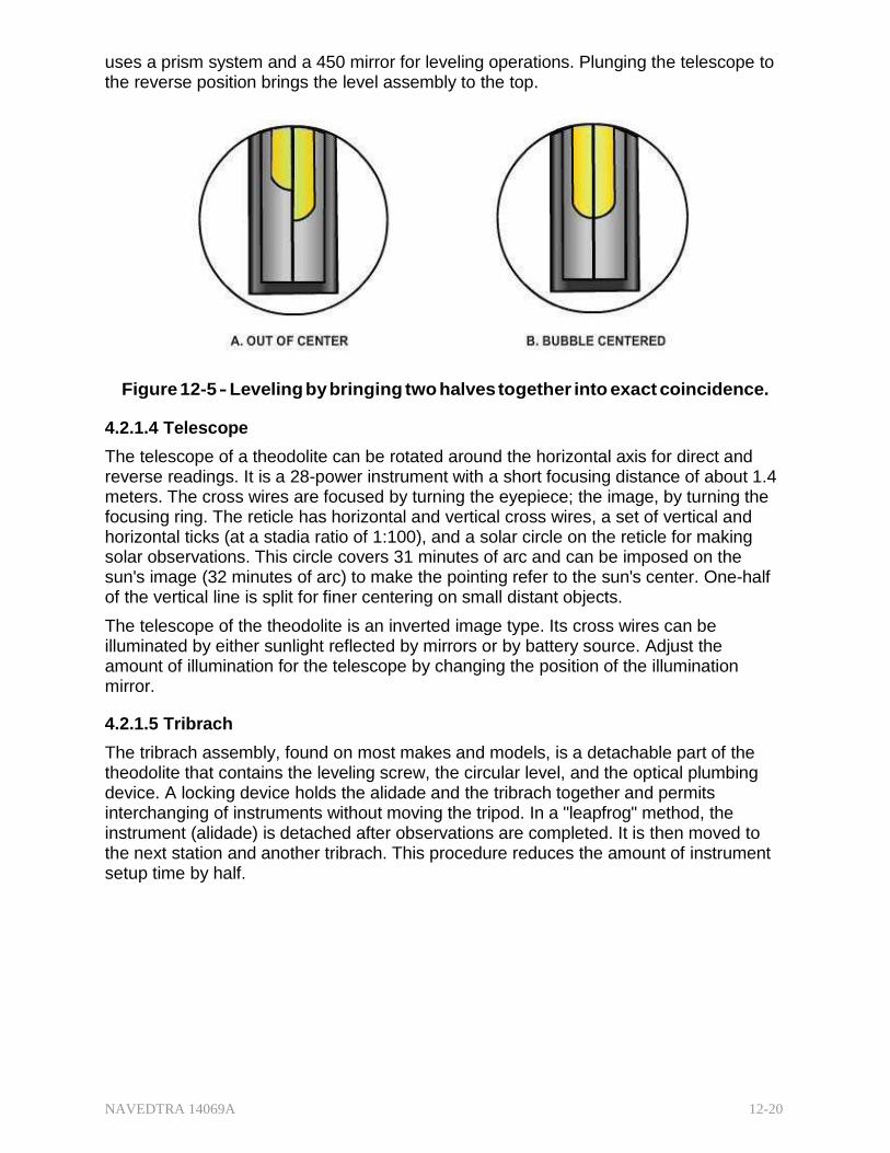
NAVEDTRA 14069A 12-20
uses a prism system and a 450 mirror for leveling operations. Plunging the telescope to the reverse position brings the level assembly to the top.
Figure 12-5 - Leveling by bringing two halves together into exact coincidence.
4.2.1.4 Telescope
The telescope of a theodolite can be rotated around the horizontal axis for direct and reverse readings. It is a 28-power instrument with a short focusing distance of about 1.4 meters. The cross wires are focused by turning the eyepiece; the image, by turning the focusing ring. The reticle has horizontal and vertical cross wires, a set of vertical and horizontal ticks (at a stadia ratio of 1:100), and a solar circle on the reticle for making solar observations. This circle covers 31 minutes of arc and can be imposed on the sun's image (32 minutes of arc) to make the pointing refer to the sun's center. One-half of the vertical line is split for finer centering on small distant objects.
The telescope of the theodolite is an inverted image type. Its cross wires can be illuminated by either sunlight reflected by mirrors or by battery source. Adjust the amount of illumination for the telescope by changing the position of the illumination mirror.
4.2.1.5 Tribrach
The tribrach assembly, found on most makes and models, is a detachable part of the theodolite that contains the leveling screw, the circular level, and the optical plumbing device. A locking device holds the alidade and the tribrach together and permits interchanging of instruments without moving the tripod. In a "leapfrog" method, the instrument (alidade) is detached after observations are completed. It is then moved to the next station and another tribrach. This procedure reduces the amount of instrument setup time by half.
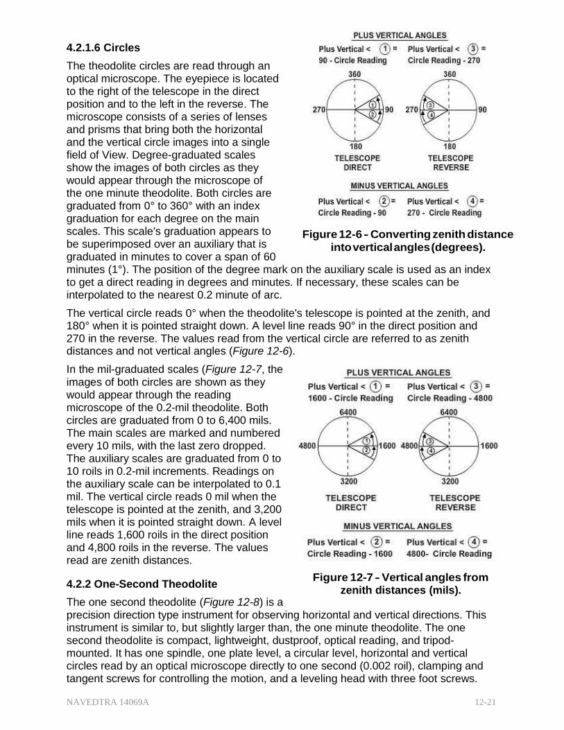
NAVEDTRA 14069A 12-21
4.2.1.6 Circles
The theodolite circles are read through an optical microscope. The eyepiece is located to the right of the telescope in the direct position and to the left in the reverse. The microscope consists of a series of lenses and prisms that bring both the horizontal and the vertical circle images into a single field of View. Degree-graduated scales show the images of both circles as they would appear through the microscope of the one minute theodolite. Both circles are graduated from 0° to 360° with an index graduation for each degree on the main scales. This scale's graduation appears to be superimposed over an auxiliary that is graduated in minutes to cover a span of 60
Figure 12-6 - Converting zenith distance
into vertical angles (degrees).
minutes (1°). The position of the degree mark on the auxiliary scale is used as an index to get a direct reading in degrees and minutes. If necessary, these scales can be interpolated to the nearest 0.2 minute of arc.
The vertical circle reads 0° when the theodolite's telescope is pointed at the zenith, and 180° when it is pointed straight down. A level line reads 90° in the direct position and 270 in the reverse. The values read from the vertical circle are referred to as zenith distances and not vertical angles (Figure 12-6).
In the mil-graduated scales (Figure 12-7, the images of both circles are shown as they would appear through the reading microscope of the 0.2-mil theodolite. Both circles are graduated from 0 to 6,400 mils. The main scales are marked and numbered every 10 mils, with the last zero dropped. The auxiliary scales are graduated from 0 to 10 roils in 0.2-mil increments. Readings on the auxiliary scale can be interpolated to 0.1 mil. The vertical circle reads 0 mil when the telescope is pointed at the zenith, and 3,200 mils when it is pointed straight down. A level line reads 1,600 roils in the direct position and 4,800 roils in the reverse. The values read are zenith distances.
4.2.2 One-Second Theodolite
The one second theodolite (Figure 12-8) is a
Figure 12-7 - Vertical angles from zenith distances (mils).
precision direction type instrument for observing horizontal and vertical directions. This instrument is similar to, but slightly larger than, the one minute theodolite. The one second theodolite is compact, lightweight, dustproof, optical reading, and tripod- mounted. It has one spindle, one plate level, a circular level, horizontal and vertical circles read by an optical microscope directly to one second (0.002 roil), clamping and tangent screws for controlling the motion, and a leveling head with three foot screws.
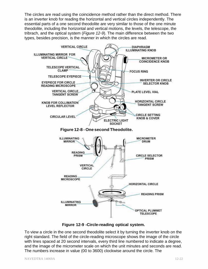
NAVEDTRA 14069A 12-22
The circles are read using the coincidence method rather than the direct method. There is an inverter knob for reading the horizontal and vertical circles independently. The essential parts of a one second theodolite are very similar to those of the one minute theodolite, including the horizontal and vertical motions, the levels, the telescope, the tribrach, and the optical system (Figure 12-9). The main difference between the two types, besides precision, is the manner in which the circles are read.
Figure 12-8 - One second Theodolite.
Figure 12-9 -Circle-reading optical system.
To view a circle in the one second theodolite select it by turning the inverter knob on the right standard. The field of the circle-reading microscope shows the image of the circle with lines spaced at 20 second intervals, every third line numbered to indicate a degree, and the image of the micrometer scale on which the unit minutes and seconds are read. The numbers increase in value (00 to 3600) clockwise around the circle. The
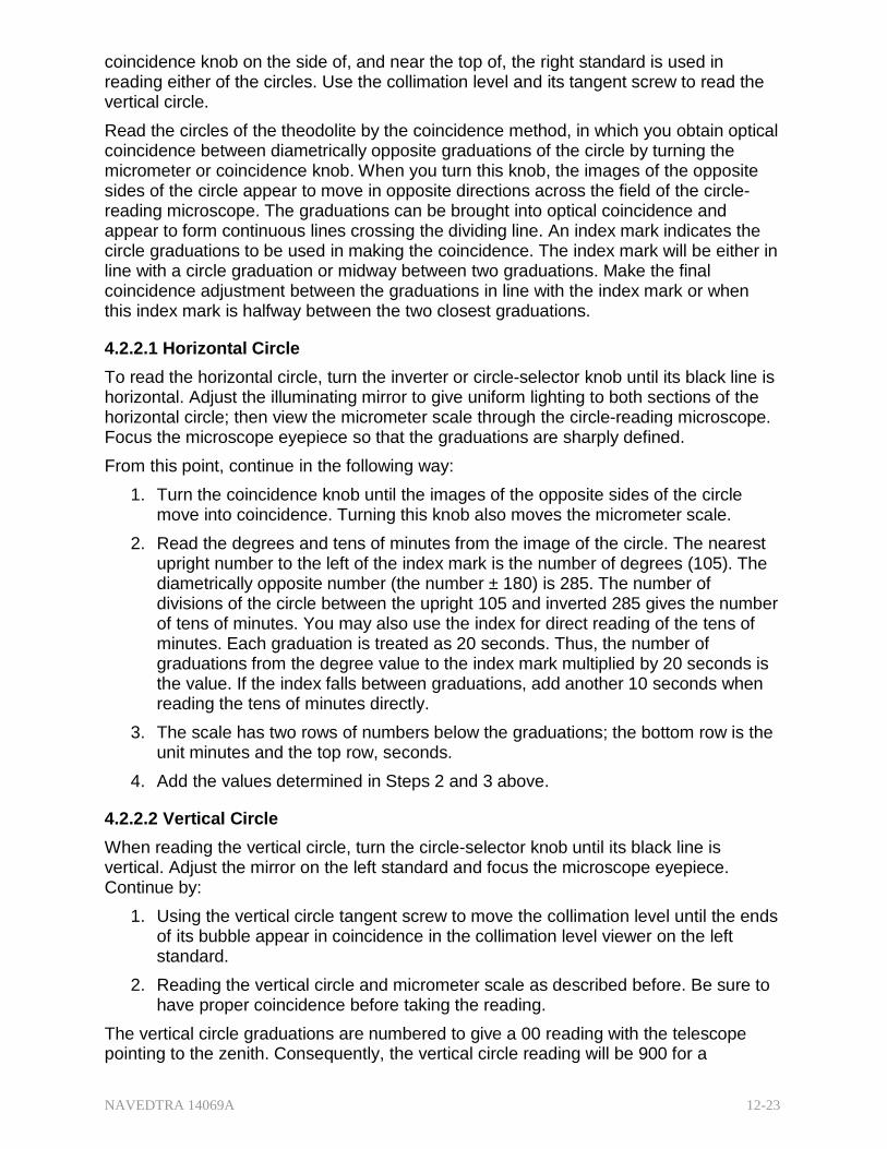
NAVEDTRA 14069A 12-23
coincidence knob on the side of, and near the top of, the right standard is used in reading either of the circles. Use the collimation level and its tangent screw to read the vertical circle.
Read the circles of the theodolite by the coincidence method, in which you obtain optical coincidence between diametrically opposite graduations of the circle by turning the micrometer or coincidence knob. When you turn this knob, the images of the opposite sides of the circle appear to move in opposite directions across the field of the circle- reading microscope. The graduations can be brought into optical coincidence and appear to form continuous lines crossing the dividing line. An index mark indicates the circle graduations to be used in making the coincidence. The index mark will be either in line with a circle graduation or midway between two graduations. Make the final coincidence adjustment between the graduations in line with the index mark or when this index mark is halfway between the two closest graduations.
4.2.2.1 Horizontal Circle
To read the horizontal circle, turn the inverter or circle-selector knob until its black line is horizontal. Adjust the illuminating mirror to give uniform lighting to both sections of the horizontal circle; then view the micrometer scale through the circle-reading microscope. Focus the microscope eyepiece so that the graduations are sharply defined.
From this point, continue in the following way:
1. Turn the coincidence knob until the images of the opposite sides of the circle move into coincidence. Turning this knob also moves the micrometer scale.
2. Read the degrees and tens of minutes from the image of the circle. The nearest upright number to the left of the index mark is the number of degrees (105). The diametrically opposite number (the number ± 180) is 285. The number of divisions of the circle between the upright 105 and inverted 285 gives the number of tens of minutes. You may also use the index for direct reading of the tens of minutes. Each graduation is treated as 20 seconds. Thus, the number of graduations from the degree value to the index mark multiplied by 20 seconds is the value. If the index falls between graduations, add another 10 seconds when reading the tens of minutes directly.
3. The scale has two rows of numbers below the graduations; the bottom row is the unit minutes and the top row, seconds.
4. Add the values determined in Steps 2 and 3 above. 4.2.2.2 Vertical Circle
When reading the vertical circle, turn the circle-selector knob until its black line is vertical. Adjust the mirror on the left standard and focus the microscope eyepiece. Continue by:
1. Using the vertical circle tangent screw to move the collimation level until the ends of its bubble appear in coincidence in the collimation level viewer on the left standard.
2. Reading the vertical circle and micrometer scale as described before. Be sure to have proper coincidence before taking the reading.
The vertical circle graduations are numbered to give a 00 reading with the telescope pointing to the zenith. Consequently, the vertical circle reading will be 900 for a
NAVEDTRA 14069A 12-24
horizontal sight with the telescope direct and 2700 for a horizontal sight with the telescope reversed.
There are two separate occasions for setting the horizontal circle of the theodolite. In the first case, set the circle to read a given value with the telescope pointed at a target. With the theodolite pointed at the target and with the azimuth clamp tightened, set the circle as follows: Set the micrometer scale to read the unit minutes and the seconds of the given values. Then, with the circle-setting knob, turn the circle until you obtain coincidence at the degree and tens of minutes value of the given reading. This setting normally can be made accurately to plus or minus five seconds. After the circle is set in this manner, determining the actual reading.
In the second case, set the circle to a given angle. When measuring a predetermined angle, first point the instrument along the initial line from which the angle is to be measured and read the circle. Add the value of the angle to the circle reading to determine the circle reading for the second pointing. Set the micrometer scale to read the unit minutes and the seconds of the value to be set on the circle. Then turn the instrument in azimuth and make coincidence at the degrees and tens of minutes value to be set. The predetermined value can usually be set on the circle in this way to plus or minus two seconds.
4.3.0 Precision Level
The self-leveling level has in recent years become standard equipment in the Naval Construction Force Table of Allowance (TOA). These precision instruments are like conventional levels with several additional features.
A precision level is equipped with an extra-sensitive level vial. The sensitivity of a level vial is usually expressed in terms of the size of the vertical angle the telescope must be moved to cause the bubble in the level vial to move from one graduation to the next.
The sensitivity of the level vial on an ordinary level is about 20 seconds. On a precise level, the level vial sensitivity is about two seconds. The telescope level vial on an ordinary transit has a sensitivity of about 30 seconds. The more sensitive the level vial is, the more difficult it is to center the bubble. If the level vial on an ordinary level had a sensitivity as high as two seconds, the smallest possible movement of the level screw would cause a large motion of the bubble.
For this reason, a precise level is usually also a tilting level. On a tilting level, the telescope is hinged at the objective end in order to raise or lower the eyepiece end. The eyepiece end rests on a finely threaded micrometer screw that turns to raise or lower the eyepiece end in small increments. The instrument is first leveled, as nearly as possible, following the typical steps. The bubble is then brought to exact center by the use of the micrometer screw.
4.3.1 Level
The military level (Figure 12-10) is a semi-precise level designed for more precise work than the engineer's level. The telescope is 30-power, 10-inch-long, interior-focusing with an inverting eyepiece and an enclosed fixed reticle. The reticle is mounted internally and cannot be adjusted as in other instruments. It contains cross wires and a set of stadia hairs. The objective is focused by an internal field lens through a rack and pinion, controlled by a knob on the upper right-hand side of the telescope.
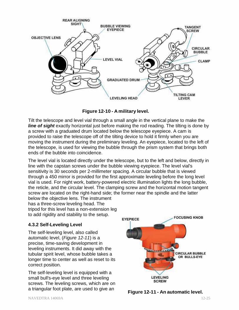
NAVEDTRA 14069A 12-25
Figure 12-10 - A military level.
Tilt the telescope and level vial through a small angle in the vertical plane to make the line of sight exactly horizontal just before making the rod reading. The tilting is done by a screw with a graduated drum located below the telescope eyepiece. A cam is provided to raise the telescope off of the tilting device to hold it firmly when you are moving the instrument during the preliminary leveling. An eyepiece, located to the left of the telescope, is used for viewing the bubble through the prism system that brings both ends of the bubble into coincidence.
The level vial is located directly under the telescope, but to the left and below, directly in line with the capstan screws under the bubble viewing eyepiece. The level vial's sensitivity is 30 seconds per 2-millimeter spacing. A circular bubble that is viewed through a 450 mirror is provided for the first approximate leveling before the long level vial is used. For night work, battery-powered electric illumination lights the long bubble, the reticle, and the circular level. The clamping screw and the horizontal motion tangent screw are located on the right-hand side; the former near the spindle and the latter below the objective lens. The instrument has a three-screw leveling head. The tripod for this level has a non-extension leg to add rigidity and stability to the setup.
4.3.2 Self-Leveling Level
The self-leveling level, also called automatic level, (Figure 12-11) is a precise, time-saving development in leveling instruments. It did away with the tubular spirit level, whose bubble takes a longer time to center as well as reset to its correct position.
The self-leveling level is equipped with a small bull's-eye level and three leveling screws. The leveling screws, which are on a triangular foot plate, are used to give an
Figure 12-11 - An automatic level.
NAVEDTRA 14069A 12-26
approximate center of the bull's-eye level. The line of sight automatically becomes horizontal and remains horizontal as long as the bubble remains approximately centered. A prismatic device called a compensator makes this possible. The compensator is suspended on fine, nonmagnetic wires. The action of gravity on the compensator causes the optical system to swing into the position that defines a horizontal sight. This horizontal line of sight is maintained despite a slight out of level of the telescope or even when a slight disturbance occurs on the instrument.
4.3.0 Hand Level
The hand level, like all surveying levels, is an instrument that combines a level vial and a sighting device. It is generally used for rough leveling work. In cross-sectional work, for example, terrain irregularities may cause elevations to go beyond the instrument range from a setup. A hand level is useful for extending approximate elevations off the control survey line beyond the limits of the instruments.
For greater stability, both hand levels may be rested against a tree, rod, range pole, or on top of a staff. A horizontal line, called an index line, is provided in the sight tube as a reference line. The level vial is mounted atop a slot in the sight tube in which a reflector is set at a 45° angle. This permits the observer, while sighting through the tube, to see the landscape or object, the position of the bubble in the vial, and the index line at the same time. The distances over which a hand level is sighted are comparatively short; therefore, it provides no magnification for the sighting.
The Abney hand level is more specialized than the Locke type. It has a clinometer for measuring the vertical angle and the percent of grade. The clinometers has a reversible graduated arc assembly mounted on one side. The lower side of the arc is graduated in degrees, and the upper side, in percent of slope. The level vial is attached to the axis of rotation at the index arm. When the index arm is set at zero, the clinometer is used like a plain hand level. The bubble is centered by moving the arc and not the sighting tube as is the case in the plain hand level. Thus, the difference between the line of sight and the level bubble axis can be read in degrees or percent of slope from the position of the index arm of the arc. The 45° reflector and the sighting principle with its view of the landscape, bubble, and index line are the same as in the plain hand level.
Test your Knowledge (Select the Correct Response)
9. What part of an engineer's transit serves the same function as the tribrach of the theodolite?
A. Leveling assembly B. Lower plate C. Upper plate D. Standard
4.4.0 Trimble® 5600 and Terramodel™ Software
The Trimble® 5600 Total Station (Figure 12-12) is designed to support integrated surveying by combining GPS and optical survey data from the field into an electronic file that can used with Trimble office software for processing. Integrated surveying enables you to maximize the best of both surveying techniques for optimal efficiency in the field.
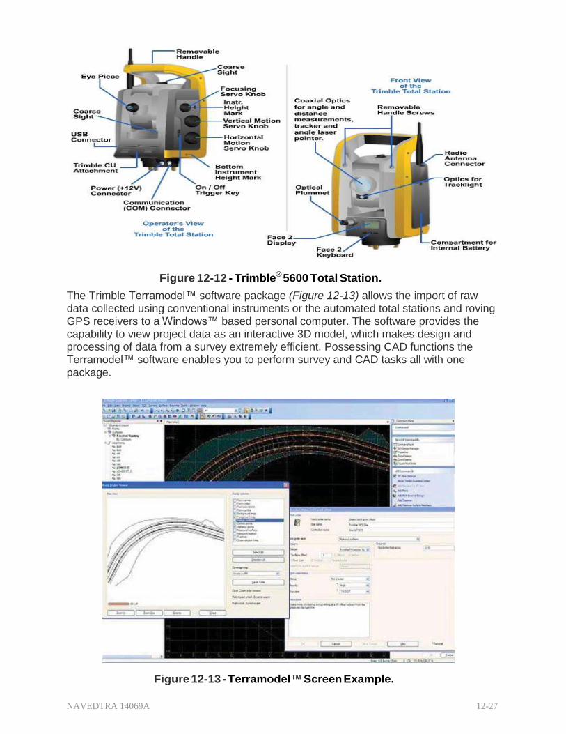
NAVEDTRA 14069A 12-27
Figure 12-12 - Trimble® 5600 Total Station.
The Trimble Terramodel™ software package (Figure 12-13) allows the import of raw data collected using conventional instruments or the automated total stations and roving GPS receivers to a Windows™ based personal computer. The software provides the capability to view project data as an interactive 3D model, which makes design and processing of data from a survey extremely efficient. Possessing CAD functions the Terramodel™ software enables you to perform survey and CAD tasks all with one package.
Figure 12-13 - Terramodel™ Screen Example.
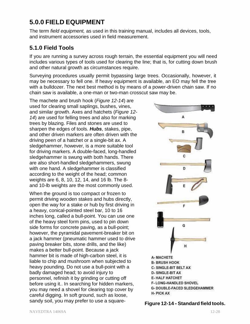
NAVEDTRA 14069A 12-28
5.0.0 FIELD EQUIPMENT
The term field equipment, as used in this training manual, includes all devices, tools, and instrument accessories used in field measurement.
5.1.0 Field Tools
If you are running a survey across rough terrain, the essential equipment you will need includes various types of tools used for clearing the line; that is, for cutting down brush and other natural growth as circumstances require.
Surveying procedures usually permit bypassing large trees. Occasionally, however, it may be necessary to fell one. If heavy equipment is available, an EO may fell the tree with a bulldozer. The next best method is by means of a power-driven chain saw. If no chain saw is available, a one-man or two-man crosscut saw may be.
The machete and brush hook (Figure 12-14) are used for clearing small saplings, bushes, vines, and similar growth. Axes and hatchets (Figure 12- 14) are used for felling trees and also for marking trees by blazing. Files and stones are used to sharpen the edges of tools. Hubs, stakes, pipe, and other driven markers are often driven with the driving peen of a hatchet or a single-bit ax. A sledgehammer, however, is a more suitable tool for driving markers. A double-faced, long-handled sledgehammer is swung with both hands. There are also short-handled sledgehammers, swung with one hand. A sledgehammer is classified according to the weight of the head; common weights are 6, 8, 10, 12, 14, and 16 lb. The 8- and 10-lb weights are the most commonly used.
When the ground is too compact or frozen to permit driving wooden stakes and hubs directly, open the way for a stake or hub by first driving in a heavy, conical-pointed steel bar, 10 to 16 inches long, called a bull-point. You can use one of the heavy steel form pins, used to pin down side forms for concrete paving, as a bull-point; however, the pyramidal pavement-breaker bit on a jack hammer (pneumatic hammer used to drive paving breaker bits, stone drills, and the like) makes a better bull-point. Because a jack hammer bit is made of high-carbon steel, it is liable to chip and mushroom when subjected to heavy pounding. Do not use a bull-point with a badly damaged head; to avoid injury to personnel, refinish it by grinding or cutting off before using it.. In searching for hidden markers, you may need a shovel for clearing top cover by careful digging. In soft ground, such as loose, sandy soil, you may prefer to use a square-
Figure 12-14 - Standard field tools.
NAVEDTRA 14069A 12-29
pointed shovel or a probing steel rod to locate buried markers.
Chipping bituminous pavement off of manhole covers and levering them up may require a pick. Sometimes you will need a crowbar for levering manhole covers. A dip needle or a battery-powered instrument called a pipe finder, similar in principle to a mine detector, helps to locate buried metal markers. These instruments are used in engineering surveys to locate utility pipelines, buried manhole and valve box covers, and the like. You can generally borrow these instruments from the utilities division of the Public Works Department (PWD) of larger shore stations.
5.2.0 Surveying Tapes
Tapes are used in surveying to measure horizontal, vertical, and slope distances. They may be made of a ribbon or a band of steel, an alloy of steel, cloth reinforced with metal, or synthetic materials. Tapes are issued in various lengths and widths and graduated in a variety of ways.
5.2.1 Metallic Tapes
A metallic tape is made of high-grade synthetic material with strong metallic strands (bronze/brass- copper wire) woven in the warped face of the tape and coated with a tough plastic for durability. Standard lengths are 50 and 100 feet.
Some are graduated in feet and inches to the nearest one-fourth inch. Others are graduated in feet and decimals of a foot to the nearest 0.05 feet. Metallic tapes are generally used for rough measurements, such as cross-sectional work, road-work slope staking, side shots in topographic surveys, and many others in the same category. Nonmetallic tapes woven from synthetic yarn, such as nylon, and coated with plastic are available; some surveyors prefer to use tapes of this type. Nonmetallic tapes are of special value to power and utility field personnel, especially when they are working in the vicinity of high voltage circuits.
5.2.2 Steel Tapes
Direct linear measurements of ordinary or more accurate precision require a steel tape. The most commonly used length is 100 feet, but tapes are also available in 50-, 200-, 300-, and 500-feet lengths. All tapes except the 500-foot are band-types, the common band widths being % and 5/16 inch. The 500-tape is usually a flat-wire type.
Most steel tapes are graduated in feet and decimals of feet, but some are graduated in feet and inches, meters, Gunter's links, and chains or other linear units. From now on, when we discuss a tape, we will be talking about one that is graduated in feet and decimals of a foot unless stated otherwise.
Some tapes, called engineer's or direct reading tapes, are graduated in subdivisions of each foot. The tape most commonly used, however, is the so-called chain tape, on which only the first foot at the zero end of the tape is graduated in subdivisions; the main body of the tape is graduated only at every one foot mark. A steel tape is sometimes equipped with a reel on which the tape can be wound, although a tape can be, and often is, detached from the reel for convenience.
There are various types of surveying tapes; metallic tape, steel tape on an open reel, steel tape on a closed reel, and special types of low-expansion steel tape, generally called an Invar tape or Lovar tape, used in high-order work.
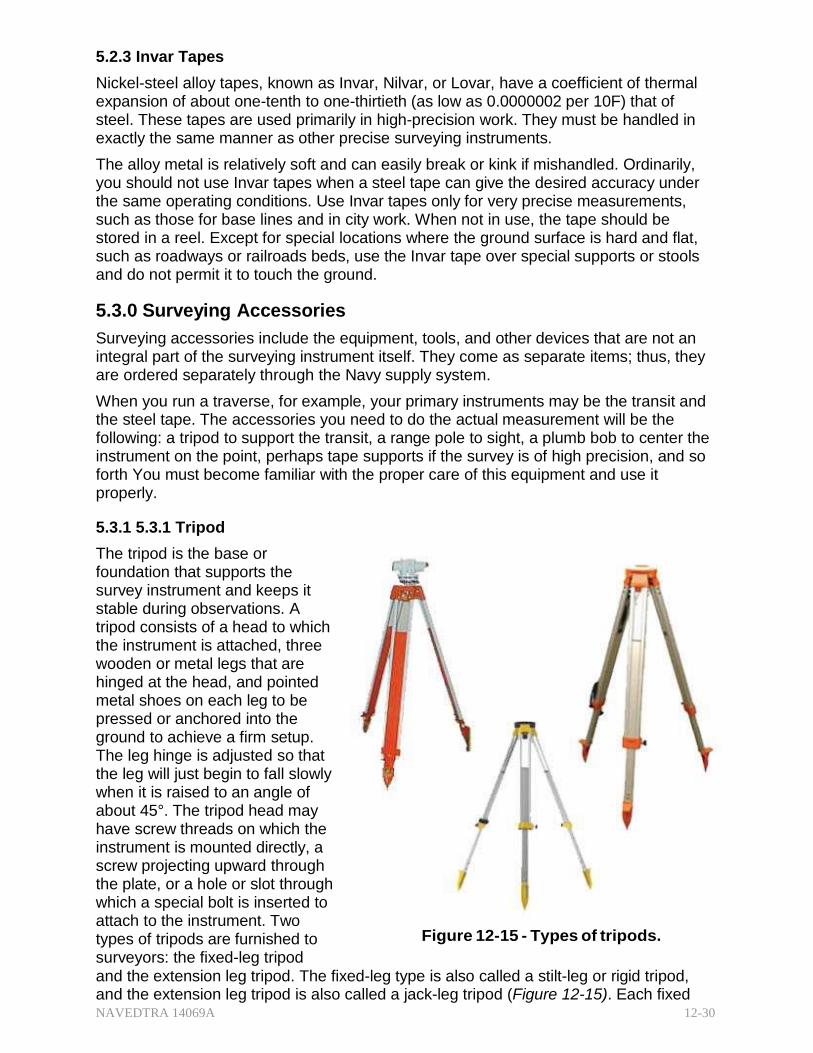
NAVEDTRA 14069A 12-30
5.2.3 Invar Tapes
Nickel-steel alloy tapes, known as Invar, Nilvar, or Lovar, have a coefficient of thermal expansion of about one-tenth to one-thirtieth (as low as 0.0000002 per 10F) that of steel. These tapes are used primarily in high-precision work. They must be handled in exactly the same manner as other precise surveying instruments.
The alloy metal is relatively soft and can easily break or kink if mishandled. Ordinarily, you should not use Invar tapes when a steel tape can give the desired accuracy under the same operating conditions. Use Invar tapes only for very precise measurements, such as those for base lines and in city work. When not in use, the tape should be stored in a reel. Except for special locations where the ground surface is hard and flat, such as roadways or railroads beds, use the Invar tape over special supports or stools and do not permit it to touch the ground.
5.3.0 Surveying Accessories
Surveying accessories include the equipment, tools, and other devices that are not an integral part of the surveying instrument itself. They come as separate items; thus, they are ordered separately through the Navy supply system.
When you run a traverse, for example, your primary instruments may be the transit and the steel tape. The accessories you need to do the actual measurement will be the following: a tripod to support the transit, a range pole to sight, a plumb bob to center the instrument on the point, perhaps tape supports if the survey is of high precision, and so forth You must become familiar with the proper care of this equipment and use it properly.
5.3.1 5.3.1 Tripod
The tripod is the base or foundation that supports the survey instrument and keeps it stable during observations. A tripod consists of a head to which the instrument is attached, three wooden or metal legs that are hinged at the head, and pointed metal shoes on each leg to be pressed or anchored into the ground to achieve a firm setup. The leg hinge is adjusted so that the leg will just begin to fall slowly when it is raised to an angle of about 45°. The tripod head may have screw threads on which the instrument is mounted directly, a screw projecting upward through the plate, or a hole or slot through which a special bolt is inserted to attach to the instrument. Two types of tripods are furnished to surveyors: the fixed-leg tripod
Figure 12-15 - Types of tripods.
and the extension leg tripod. The fixed-leg type is also called a stilt-leg or rigid tripod, and the extension leg tripod is also called a jack-leg tripod (Figure 12-15). Each fixed
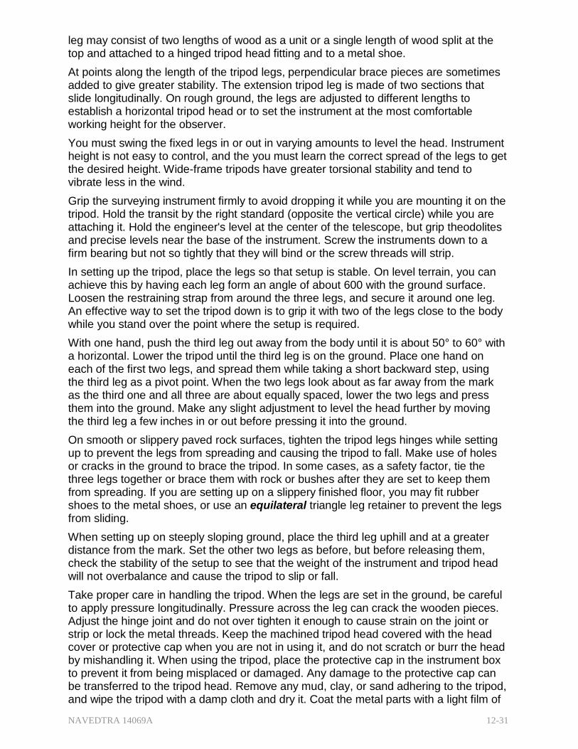
NAVEDTRA 14069A 12-31
leg may consist of two lengths of wood as a unit or a single length of wood split at the top and attached to a hinged tripod head fitting and to a metal shoe.
At points along the length of the tripod legs, perpendicular brace pieces are sometimes added to give greater stability. The extension tripod leg is made of two sections that slide longitudinally. On rough ground, the legs are adjusted to different lengths to establish a horizontal tripod head or to set the instrument at the most comfortable working height for the observer.
You must swing the fixed legs in or out in varying amounts to level the head. Instrument height is not easy to control, and the you must learn the correct spread of the legs to get the desired height. Wide-frame tripods have greater torsional stability and tend to vibrate less in the wind.
Grip the surveying instrument firmly to avoid dropping it while you are mounting it on the tripod. Hold the transit by the right standard (opposite the vertical circle) while you are attaching it. Hold the engineer's level at the center of the telescope, but grip theodolites and precise levels near the base of the instrument. Screw the instruments down to a firm bearing but not so tightly that they will bind or the screw threads will strip.
In setting up the tripod, place the legs so that setup is stable. On level terrain, you can achieve this by having each leg form an angle of about 600 with the ground surface. Loosen the restraining strap from around the three legs, and secure it around one leg. An effective way to set the tripod down is to grip it with two of the legs close to the body while you stand over the point where the setup is required.
With one hand, push the third leg out away from the body until it is about 50° to 60° with a horizontal. Lower the tripod until the third leg is on the ground. Place one hand on each of the first two legs, and spread them while taking a short backward step, using the third leg as a pivot point. When the two legs look about as far away from the mark as the third one and all three are about equally spaced, lower the two legs and press them into the ground. Make any slight adjustment to level the head further by moving the third leg a few inches in or out before pressing it into the ground.
On smooth or slippery paved rock surfaces, tighten the tripod legs hinges while setting up to prevent the legs from spreading and causing the tripod to fall. Make use of holes or cracks in the ground to brace the tripod. In some cases, as a safety factor, tie the three legs together or brace them with rock or bushes after they are set to keep them from spreading. If you are setting up on a slippery finished floor, you may fit rubber shoes to the metal shoes, or use an equilateral triangle leg retainer to prevent the legs from sliding.
When setting up on steeply sloping ground, place the third leg uphill and at a greater distance from the mark. Set the other two legs as before, but before releasing them, check the stability of the setup to see that the weight of the instrument and tripod head will not overbalance and cause the tripod to slip or fall.
Take proper care in handling the tripod. When the legs are set in the ground, be careful to apply pressure longitudinally. Pressure across the leg can crack the wooden pieces. Adjust the hinge joint and do not over tighten it enough to cause strain on the joint or strip or lock the metal threads. Keep the machined tripod head covered with the head cover or protective cap when you are not in using it, and do not scratch or burr the head by mishandling it. When using the tripod, place the protective cap in the instrument box to prevent it from being misplaced or damaged. Any damage to the protective cap can be transferred to the tripod head. Remove any mud, clay, or sand adhering to the tripod, and wipe the tripod with a damp cloth and dry it. Coat the metal parts with a light film of
NAVEDTRA 14069A 12-32
oil or wipe them with an oily cloth. Foreign matter can get into hinged joints or on the machined surfaces and cause wear. Stability is the tripod's greatest asset. Instability, wear, or damaged bearing surfaces on the tripod can evolve into unexplainable errors in the final survey results.
5.3.2 Range Pole
A range pole (also called a lining rod) is a wood or metal pole, usually about eight feet long and about 1/2 to one inch in diameter; it is has a steel point or shoe and painted bands of alternating red and white to increase its visibility. The range pole is held vertically on a point or plumbed over a point, so the point may be observed through an optical instrument. Its primary use is as a sighting rod for linear or angular measurements. For work of ordinary precision, chainmen may keep on line by observing a range pole. A range pole may also be used for approximate stadia measurement.
5.3.3 Plumb Bob, Cord, and Target
A plumb bob is a pointed, tapered brass or bronze weight that is suspended from a cord for the general purpose of determining the plumb line from a point on the ground. Common weights for plumb bobs are 6, 8, 10, 12, 14, 16, 18, and 24 oz; the 12- and the 16- oz are the most popular.
A plumb bob is a precision instrument and you must care for it as such. If the tip becomes bent, the cord from which the bob is suspended will not occupy the true plumb line over the point indicated by the tip. A plumb bob usually has a detachable tip, so if the tip becomes damaged, you can renew it without replacing the entire instrument.
Each survey party member should be equipped with a leather sheath, and the bob should be placed in the sheath whenever it is not in use. To make the cord from a plumb bob more conspicuous for observation purposes, attach an oval form aluminum target (Figure 12-16, View A). The oval target has reinforced edges, and the face is enameled in quadrants alternately with red and white. Also, you may use a flat rectangular plastic target (Figure 12-16, View B). It has rounded corners with alternate red and white quadrants on its face. These plumb bob string targets are pocket size with approximate dimensions of 2 by 4 inches.
5.3.4 tical Plumbing Assembly
The optical plumbing assembly, or plummet, is a device built into the alidade or the tribrach of Figure 12-16 - The plumb bob, cord,
and target.
NAVEDTRA 14069A 12-33
some instruments to center the instrument over a point. The plummet consists of a small prismatic telescope with a cross wire or marked circle reticle adjusted to be in line with the vertical axis of the instrument. After the instrument is leveled, a sighting through the plummet will check the centering over a point quickly. The advantages of the plummet over the plumb bob are that it permits the observer to center over a point from the height of the instrument stand, and it is not affected by the wind. The plummet is especially useful for work on high stands. A plumb bob requires someone at ground level to steady it and to inform the observer on the platform how to move the instrument and when it is exactly over the point. With the plummet, the observer does the centering and checking.
5.3.5 Tape Accessories
There is usually a leather thong at each end of a tape by which you can hold the tape when using the full length. When using only part of the tape, you can hold the zero end by the thong, and hold the tape at an intermediate point by means of a tape clamp handle. When a tape is not supported throughout- that is, when it is held above ground between a couple of crew members-you must apply a correction for the amount of sag in the tape. To make this correction, apply a certain amount of tension using a tension scale and/or spring balance (Figure 12-17).
The tension scale is graduated in pounds from 0 to 30. It is clipped to the eye at the end of the tape, and the tension is applied until the desired reading appears on the scale. A pair of staffs can be used to make the work easier. Wrap the rawhide thongs around the staff at a convenient height and grip them firmly. Brace the bottom end of the staff against the foot and tuck the upper end under the arm. Apply tension by using the shoulder and leaning against the poles. Use the spring balance in a similar fashion for work of higher precision.
The stool device is called a tapping stool or chaining buck and is used in high precision work. It is a metal three-legged stand with an adjustable sliding
Figure 12-17 - The tension scale and spring balance.
head and a hand wheel operating device for locking the plate (the top surface of the sliding head) in any desired position. A line is scribed on the plate. During taping operations, move the head until the scribed line is directly under a particular graduation on the tape; then use the hand wheel to lock the head. When the tape is shifted ahead to measure the next interval, hold the graduation exactly over the line until the next stool is adjusted and locked. The basic purpose of taping stools is to furnish stable, elevated surfaces on which taped distances can be marked accurately. When stools are not available, 2 by 4s or 4 by 4s are often driven into the ground for use as chaining bucks.
NAVEDTRA 14069A 12-34
The length of a tape varies with the temperature, and the precision of a survey may require you to apply corrections for this. For work of ordinary precision, you can assume that the temperature of the tape is about the same as that of the air. For work requiring higher precision, attach a tape thermometer to the tape. For very precise work, use two thermometers, one positioned at each end. If the two indicate different temperatures, use the mean between them.
5.3.6 5.3.6 Chaining Pin
A chaining pin (also called a taping arrow) is a metal pin about one foot long. It has a circular eye at one end and a point for pushing it into the ground at the other. These pins come in sets of 11 pins, carried on a wire ring passed through the eyes in the pins or in a sheath called a quiver.
Chaining pins can be used for the temporary marking of points in a great variety of situations, but they are used most frequently to keep count of tape increments in the chaining of long distances.
5.3.7 eveling Rod, Target, and Rod Level
A leveling rod, is a tape supported vertically and is used to measure the vertical distance (difference in elevation) between a line of sight and a required point above or below it. This point may be a permanent elevation (bench mark), or it may be some natural or constructed surface.
There are several types of leveling rods. The most popular of all, the Philadelphia rod, (Figure 12-18), is a graduated wooden rod made of two sections and extendable from 7 to 13 feet. Each foot is subdivided into hundredths of a foot. Instead of each hundredth being marked with a line or tick, the distance between alternate ones is painted black on a white background. Thus, the value for each hundredth is the distance between the colors; the top of the black, even values, the bottom of the black, odd values. The tenths are numbered in black, the feet in red. This rod may be used with the level, transit, theodolite, and with the hand level on occasion to measure the difference in elevation.
The instrumentman reads the leveling rod directly by the sighting through the telescope, or it may be target-read. Conditions that hinder direct reading, such
Figure 12-18 - The Philadelphia rod.
as poor visibility, long sights, and sights partially obstructed by, for example, brush or leaves, sometimes necessitate using targets. The target is also used to mark a rod reading when numerous points are set to the same elevation from one instrument setup. Targets for the Philadelphia rod are usually oval, with the long axis at right angles to the rod, and the quadrants of the target painted alternately red and white. The target is held in place on the rod by a C-clamp and a thumbscrew. A lever on the face of the target is used for fine adjustment of the target to the line of sight of the level. The targets have rectangular openings approximately the width of the rod and 0.15 feet high through which you can see the face of the rod. A linear vernier scale is mounted on the edge of
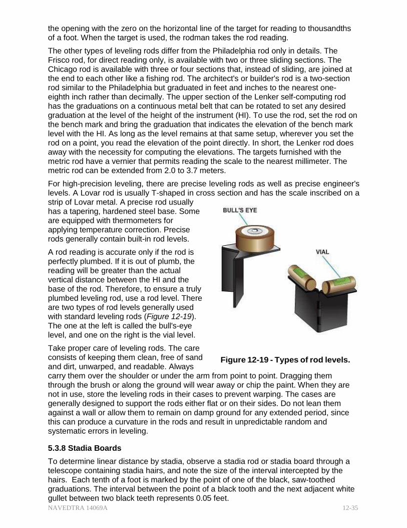
NAVEDTRA 14069A 12-35
the opening with the zero on the horizontal line of the target for reading to thousandths of a foot. When the target is used, the rodman takes the rod reading.
The other types of leveling rods differ from the Philadelphia rod only in details. The Frisco rod, for direct reading only, is available with two or three sliding sections. The Chicago rod is available with three or four sections that, instead of sliding, are joined at the end to each other like a fishing rod. The architect's or builder's rod is a two-section rod similar to the Philadelphia but graduated in feet and inches to the nearest one- eighth inch rather than decimally. The upper section of the Lenker self-computing rod has the graduations on a continuous metal belt that can be rotated to set any desired graduation at the level of the height of the instrument (HI). To use the rod, set the rod on the bench mark and bring the graduation that indicates the elevation of the bench mark level with the HI. As long as the level remains at that same setup, wherever you set the rod on a point, you read the elevation of the point directly. In short, the Lenker rod does away with the necessity for computing the elevations. The targets furnished with the metric rod have a vernier that permits reading the scale to the nearest millimeter. The metric rod can be extended from 2.0 to 3.7 meters.
For high-precision leveling, there are precise leveling rods as well as precise engineer's levels. A Lovar rod is usually T-shaped in cross section and has the scale inscribed on a strip of Lovar metal. A precise rod usually has a tapering, hardened steel base. Some are equipped with thermometers for applying temperature correction. Precise rods generally contain built-in rod levels.
A rod reading is accurate only if the rod is perfectly plumbed. If it is out of plumb, the reading will be greater than the actual vertical distance between the HI and the base of the rod. Therefore, to ensure a truly plumbed leveling rod, use a rod level. There are two types of rod levels generally used with standard leveling rods (Figure 12-19). The one at the left is called the bull's-eye level, and one on the right is the vial level.
Take proper care of leveling rods. The care consists of keeping them clean, free of sand and dirt, unwarped, and readable. Always
Figure 12-19 - Types of rod levels.
carry them over the shoulder or under the arm from point to point. Dragging them through the brush or along the ground will wear away or chip the paint. When they are not in use, store the leveling rods in their cases to prevent warping. The cases are generally designed to support the rods either flat or on their sides. Do not lean them against a wall or allow them to remain on damp ground for any extended period, since this can produce a curvature in the rods and result in unpredictable random and systematic errors in leveling.
5.3.8 Stadia Boards
To determine linear distance by stadia, observe a stadia rod or stadia board through a telescope containing stadia hairs, and note the size of the interval intercepted by the hairs. Each tenth of a foot is marked by the point of one of the black, saw-toothed graduations. The interval between the point of a black tooth and the next adjacent white gullet between two black teeth represents 0.05 feet.
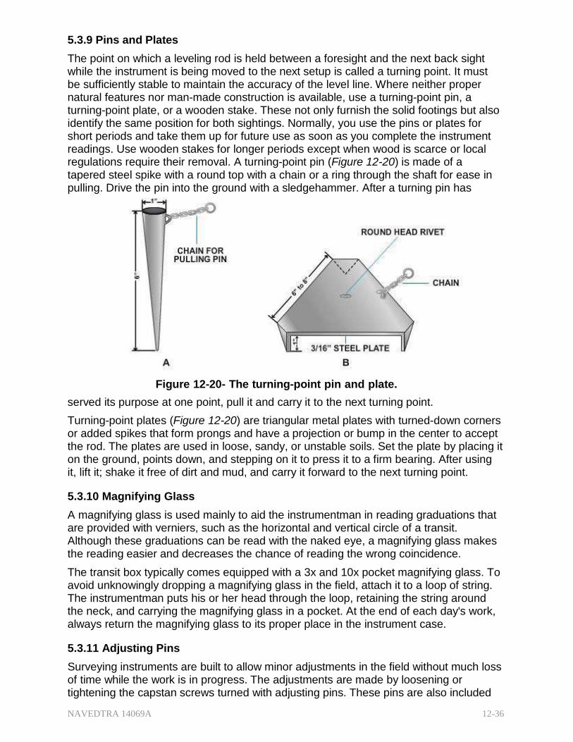
NAVEDTRA 14069A 12-36
5.3.9 Pins and Plates
The point on which a leveling rod is held between a foresight and the next back sight while the instrument is being moved to the next setup is called a turning point. It must be sufficiently stable to maintain the accuracy of the level line. Where neither proper natural features nor man-made construction is available, use a turning-point pin, a turning-point plate, or a wooden stake. These not only furnish the solid footings but also identify the same position for both sightings. Normally, you use the pins or plates for short periods and take them up for future use as soon as you complete the instrument readings. Use wooden stakes for longer periods except when wood is scarce or local regulations require their removal. A turning-point pin (Figure 12-20) is made of a tapered steel spike with a round top with a chain or a ring through the shaft for ease in pulling. Drive the pin into the ground with a sledgehammer. After a turning pin has
Figure 12-20- The turning-point pin and plate.
served its purpose at one point, pull it and carry it to the next turning point.
Turning-point plates (Figure 12-20) are triangular metal plates with turned-down corners or added spikes that form prongs and have a projection or bump in the center to accept the rod. The plates are used in loose, sandy, or unstable soils. Set the plate by placing it on the ground, points down, and stepping on it to press it to a firm bearing. After using it, lift it; shake it free of dirt and mud, and carry it forward to the next turning point.
5.3.10 Magnifying Glass
A magnifying glass is used mainly to aid the instrumentman in reading graduations that are provided with verniers, such as the horizontal and vertical circle of a transit. Although these graduations can be read with the naked eye, a magnifying glass makes the reading easier and decreases the chance of reading the wrong coincidence.
The transit box typically comes equipped with a 3x and 10x pocket magnifying glass. To avoid unknowingly dropping a magnifying glass in the field, attach it to a loop of string. The instrumentman puts his or her head through the loop, retaining the string around the neck, and carrying the magnifying glass in a pocket. At the end of each day's work, always return the magnifying glass to its proper place in the instrument case.
5.3.11 Adjusting Pins
Surveying instruments are built to allow minor adjustments in the field without much loss of time while the work is in progress. The adjustments are made by loosening or tightening the capstan screws turned with adjusting pins. These pins are also included
NAVEDTRA 14069A 12-37
in the instrument box. They come in various sizes depending upon the type of instrument and the hole sizes of its capstan screws. Use the pin that fits the hole in the capstan head. A pin that is too small, will ruin the head of the screw.
Surveying instrument dealers usually replace these pins free of charge. Like the magnifying glass, adjusting pins should be carried in the pocket and not left in the instrument box while a survey is in progress. This will save a lot of valuable time when you need the pins. Do not use wires, nails, screwdrivers, and the like, as substitutes for adjusting pins.
5.3.12 Tape Repair Kit
Even though you handle the tape properly and carefully during field measurements, some tapes still break under unforeseen circumstances.
During chaining operations, when the area is quite far from the base of operations, always be sure to have a tape repair kit with you so that you can rejoin any broken tape in the field, or if you has bring an extra tape, you can take the broken tape back to the office for repair.
The tape repair kit usually contains a pair of small snips, the tape sections of proper size and graduations, a hand punch or bench punch with block, an assortment of small rivets, a pair of tweezers, a small hammer, and a small file. Before reusing a repaired tape, always compare it with an Invar or Lovar tape to check it for accuracy.
Test your Knowledge (Select the Correct Response)
10. Which of the following tools is best suited for driving pipe markers into surfaces?
A. A hatchet B. A single bit ax C. A sledgehammer D. A bull point
11. After you secure the restraining strap, what is the next step in setting up a tripod?
A. Hold one leg close to your body B. Hold two legs close to your body C. Spread the legs, 60 degrees apart D. Spread the legs until they form about a 50-60 degree angle with the
horizontal 12. Which of the following tape accessories should be used to hold the tape securely
at an intermediate point?
A. Tape clamp handle B. Tensions scale C. Taping stool D. Staff
6.0.0 FIELD SUPPLIES
Field supplies are a variety of materials used to mark the locations of points in the field. For example, pencils, field notebooks, and spare handles for sledgehammers are generally classified as field supplies. Every Seabee operation site may require different supplies, but your own experience and the aid of your leading petty officer will allow for
NAVEDTRA 14069A 12-38
making a comprehensive list of supplies necessary for a projected survey mission. This section describes the items generally required for a mission.
6.1.0 Survey Point Markers
The material used as a survey point marker depends upon where the point is located and whether the marker is to be temporary, semi permanent, or permanent. For example, a wooden stake can be easily driven to mark the location of a point in a grassy field, but it cannot be used to mark a point on the surface of a concrete highway.
Similarly, though a wooden stake is easy to drive in a grassy field to mark a property line corner, a marker of this kind would not last as long as a piece of pipe or a concrete monument. The following sections describe most of the material commonly used as semi permanent or permanent markers of points in the field. For purely temporary marking, it is often unnecessary to expend any marking materials. For example, a point in ordinary soil is often temporarily marked by a hole made with the point of a plumb bob, a chaining pin, or some other pointed device. In rough chaining of distances, even the mere imprint of a heel in the ground may suffice. A point on a concrete surface may be temporarily marked by an X drawn with keel (lumber crayon), a pencil, or some similar marking device. A large nail serves well as a temporary point in relatively stable ground or compacted materials.
6.1.1 Semi Permanent Markers
Wooden hubs and stakes are extensively used as semi permanent markers of points in the field. The principal distinction between the two is the fact that a hub is usually driven to bring its top flush with, or almost flush with, the ground surface. A hub is used principally to mark the station point for an instrument setup. It is usually made of two by two inch stock and is from five to twelve inches long. The average length is about eight inches. Shorter lengths are used in hard ground, longer lengths in softer ground. A surveyor's tack, made of galvanized iron or stainless steel with a depression in the center of the head, is driven into the top of the hub to locate the exact point where the instrument is to be plumbed.
Stakes improvised in the field may be cylindrical or any other shape available. However, manufactured stakes are rectangular in cross section because the faces of a stake are often inscribed with data relevant to the point the stake is marking. A stake that marks a bench mark, for instance, is inscribed with the symbol that identifies the bench mark and with the elevation. A stake that marks a station on a traverse is inscribed with the symbol of the particular station, such as 2 + 45.06. A grade stake is inscribed with the number of vertical feet of cut (material to be excavated) or of fill (material to be filled in) required to bring the elevation of the surface to the specified grade elevation.
6.1.2 Permanent Markers
Permanent station markers are used to mark points to be used for a long period of time. Horizontal and vertical control stations are generally marked with permanent markers. These markers could be in the following forms:
A bronze disk set in concrete
An iron pipe filled with concrete
A crosscut on an existing concrete structure or on a rock outcrop
A hole drilled in concrete and filled with lead or a metal rod driven into the ground with a center-punched mark to designate the exact point
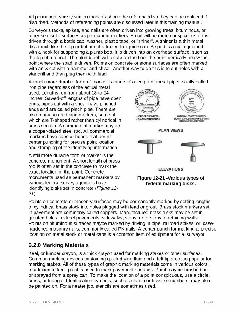
NAVEDTRA 14069A 12-39
All permanent survey station markers should be referenced so they can be replaced if disturbed. Methods of referencing points are discussed later in this training manual.
Surveyor's tacks, spikes, and nails are often driven into growing trees, bituminous, or other semisolid surfaces as permanent markers. A nail will be more conspicuous if it is driven through a bottle cap, washer, plastic tape, or "shiner". A shiner is a thin metal disk much like the top or bottom of a frozen fruit juice can. A spad is a nail equipped with a hook for suspending a plumb bob. It is driven into an overhead surface, such as the top of a tunnel. The plumb bob will locate on the floor the point vertically below the point where the spad is driven. Points on concrete or stone surfaces are often marked with an X cut with a hammer and chisel. Another way to do this is to cut holes with a star drill and then plug them with lead.
A much more durable form of marker is made of a length of metal pipe-usually called iron pipe regardless of the actual metal used. Lengths run from about 18 to 24 inches. Sawed-off lengths of pipe have open ends; pipes cut with a shear have pinched ends and are called pinch pipe. There are also manufactured pipe markers, some of which are T-shaped rather than cylindrical in cross section. A commercial marker may be a copper-plated steel rod. All commercial markers have caps or heads that permit center punching for precise point location and stamping of the identifying information.
A still more durable form of marker is the concrete monument. A short length of brass rod is often set in the concrete to mark the exact location of the point. Concrete monuments used as permanent markers by various federal survey agencies have identifying disks set in concrete (Figure 12- 21).
Figure 12-21 -Various types of
federal marking disks.
Points on concrete or masonry surfaces may be permanently marked by setting lengths of cylindrical brass stock into holes plugged with lead or grout. Brass stock markers set in pavement are commonly called coppers. Manufactured brass disks may be set in grouted holes in street pavements, sidewalks, steps, or the tops of retaining walls. Points on bituminous surfaces maybe marked by driving in pipe, railroad spikes, or case-hardened masonry nails, commonly called PK nails. A center punch for marking a precise location on metal stock or metal caps is a common item of equipment for a surveyor.
6.2.0 Marking Materials
Keel, or lumber crayon, is a thick crayon used for marking stakes or other surfaces. Common marking devices containing quick-drying fluid and a felt tip are also popular for marking stakes. All of these types of graphic marking materials come in various colors. In addition to keel, paint is used to mark pavement surfaces. Paint may be brushed on or sprayed from a spray can. To make the location of a point conspicuous, use a circle, cross, or triangle. Identification symbols, such as station or traverse numbers, may also be painted on. For a neater job, stencils are sometimes used.
NAVEDTRA 14069A 12-40
6.3.0 Flagging
Colored cloth bunting or plastic tape is often used to make stakes conspicuous so they will be easier to find or to warn Equipment Operators away. Flagging may also be used for identification purposes. For example, traverse stakes may be marked with one color, grade stakes with another. Red, yellow, orange, and white are the most popular colors for flagging.
6.4.0 Note-Keeping Materials
Field notes are usually kept in a bound, standard field notebook. Sometimes loose-leaf notebooks are used but are not generally recommended because of the chance of losing pages. Notebooks are classified as engineer's or transit field books, level books, cross section books, and so forth, depending on their use.
In a transit book, the left-hand side of the page is used for recording measurement data, and the right-hand side of the page, for remarks, sketches, and other supplementary information. The other field books generally follow the same pattern of usage. A transit or a level book may be used for recording any type of survey. You may add or modify the column headings to suit the required data you desire to record.
6.5.0 Personal Protective and Safety Equipment
In addition to the necessary field supplies and equipment, a field party must carry all necessary items of personal protective equipment, such as containers for drinking water, first-aid kits, gloves, and foul weather gear. A field survey party is usually working a considerable distance away from the main operational base. If, for example, you happen to be chaining through a marsh filled with icy water, you would not have a chance to return to the base to get your rubber boots.
You are required to wear a hard hat whenever you work in a construction area where the assigned personnel are regularly required to wear hard hats. Study all situations in advance, considering both the physical and environmental conditions-doing so may avoid situations dangerous to you and other crewmembers.
Test your Knowledge (Select the Correct Response)
15. The type of material to be used for survey point markers depends upon which of the following conditions?
A. The location of the point B. Whether the point is temporary or permanent C. The discretion of the engineer officer D. Both A and B
16. Which of the following types of markers is/are generally used for horizontal and
vertical control stations?
A. Iron pipe filled with concrete B. Bronze disks set in concrete C. A hole drilled in concrete and filled with lead D. All of the above

NAVEDTRA 14069A 12-41
Summary
In this chapter, you were presented with information relevant to safe, efficient, and effective methods and applications. Specifically, you learned about survey classification, types of survey operations, standard issue surveying instruments, field equipment, and field supplies. Through clear comprehension of surveying theory and procedures, not only will your work as a surveyor be sought out within the industry, but the quality and precision of your efforts will be second to none.
NAVEDTRA 14069A 12-42
Review Questions (Select the Correct Response) 1. In surveying, the vertical position of a point is determined in which of the
following ways?
A. Measuring directly from a datum B. Measuring indirectly from a datum C. Computation from differences in elevation that are measured directly or
indirectly from a datum
2. Increasing the areas surveyed with plane surveying methods will have what effect on (a) accuracy and (b) precision?
A. (a) Increase (b) decrease B. (a) Decrease (b) decrease C. (a) Decrease (b) increase D. (a) Increase (b) increase
3. Determining the directions and elevations of a new highway requires what kind of
survey?
A. Topographic B. Construction C. Route D. Land
4. Which of the following types of surveys is also known as an engineering survey?
A. Route B. Construction C. Topographic D. Cadastral
5. In surveying practice, which, if any, of the following tasks is considered to be an
element of office work?
A. Computing and plotting necessary information B. Taking measurements C. Collecting engineering data D. None of the above
6. In general, which, if any, of the following actions will best predetermine field
conditions and allow the selection of methods to be used for a survey?
A. Reviewing topographic maps B. Site reconnaissance C. Checking local weather conditions D. None of the above
NAVEDTRA 14069A 12-43
7. Which of the following conditions must be considered when determining the size of a field survey party?
A. The availability of equipment B. The methods that will be used C. The requirements of the survey D. All of the above
8. A transit party should consist of at least what three people?
A. Instrumentman, rodman, and note keeper B. Rodman, head chainman, and note keeper C. Party chief, head chainman, and instrumentman D. Instrumentman, head chainman, and note keeper
9. In field notebooks, all lettering should be performed in a freehand Gothic style
with which of the following grades of pencil lead?
A. 2H or 3H B. 3H or 4H C. 4H or 5H
10. Where in the field notebook should name and location of the project, the types of
measurements, and the designation of the survey unit be written?
A. Front cover B. Inside front cover C. Right-hand pages
11. Instructions for returning the notebook if it is lost belong in what part of the field
notebook?
A. On the front cover B. Inside the front cover C. On the right-hand pages
12. In keeping field notes, which of the following procedures is/are mandatory?
A. Notes are never kept on individual scraps of paper for later transcription to
notebooks. B. Erasures are never permitted; incorrect entries are lined-out and correct
entries inserted. C. Rejected pages are neatly crossed-out and referenced to the substituted
pages. D. All of the above
NAVEDTRA 14069A 12-44
13. In a measured distance that required 200 measurements, the total error was -9 units. For this error to be adjusted, each measurement must be:
A. Increased by 0.045 B. Increased by 0.450 C. Decreased by 0.450 D. Decreased by 0.045
14. A measured distance is 302.12 feet. This measurement contains what total
number of significant figures?
A. Five B. Two C. Three D. Four
15. If you round off 92.454 to three significant figures, what is the resulting number?
A. 92.4
B. 92.5
C. 92.40
D. 92.50
16. When drawing a property map, you should include which of the following items?
A. The length and direction of each boundary line B. Reference points referred from an established coordinate system C. Names of important details, such as roads, streams, and landmarks. D. All of the above
17. In an orientation symbol, a full-head arrow represents what direction or
orientation information, if any?
A. Magnetic meridian B. True meridian C. Magnetic declination D. None
18. Which of the following factors will influence the orientation of a map drawn on
standard size drawing paper?
A. The shape of the mapped area B. The size of the mapped area C. The scale of the map D. The purpose of the map
19. A map that should be used for making a model of an 18-hole golf course is
known as what type?
A. Geographic B. Planimetric C. Topographic
NAVEDTRA 14069A 12-45
20. An ordinary road map of the state of Florida is an example of what type of map?
A. Geographic B. Planimetric C. Topographic
21. A naval station base map that shows only the layout of buildings and roads is
what type of map?
A. Geographic B. Planimetric C. Topographic
22. For a one minute theodolite, which of the following actions occur when the circle
clamp is in the lever-down position?
A. The circle is clamped and turns with the telescope. B. The circle is clamped and the telescope turns independently. C. The circle is unclamped and the telescope turns independently. D. The circle is unclamped and turns with the telescope.
23. The lower half of the vertical line on the reticle of a theodolite is split for what
purpose?
A. To center triangular-shaped distant objects B. To determine the width of distant objects C. To center small distant objects D. To determine the height of distant objects
24. What are the values read from the vertical circle of a theodolite called?
A. Vertical angles B. Direct angles C. Zenith distances D. Direct distances
25. What part of a one second theodolite is used to select whether the angle being
read is a vertical or horizontal angle?
A. Circle tangent screw B. Inverter knob (circle-selector) C. Circle setting knob D. Circular level
26. The difference between two diametrically opposite members on the circle of a
one second theodolite as viewed through the circle reading microscope is equal to plus or minus how many degrees?
A. 90
B. 180
C. 270
D. 360
NAVEDTRA 14069A 12-46
27. The bubble of a level vial on the surveying instrument may become increasingly difficult to center because of what factor?
A. Temperature B. Vial age C. Humidity D. Vial sensitivity
28. On a tilting level, which of the following screws is used to bring the bubble to the
exact center?
A. Tangent B. Micrometer C. Leveling D. Centering
29. The purpose of the compensator in a self-leveling level is to compensate for
which of the following factors?
A. Misalignment of the vertical hair only B. Misalignment of the horizontal hair only C. Misalignment of both the vertical and horizontal hairs D. A slight out-of-level of the telescope
30. Which of the following tools should you use when cleaning away small saplings
and vines?
A. Chain saw B. Brush hook C. Coping saw D. Bull point
31. Which of the following tools should you use to lift a manhole cover?
A. A long-handled shovel B. A crowbar C. A long-bladed screwdriver D. A machete
32. Which, if any, of the following devices is used to locate buried metal markers?
A. Dip needle B. Mine detector C. Probing steel D. None of the above
NAVEDTRA 14069A 12-47
33. Which of the following tapes should be used for the high-precision measurement of a base line that is in the vicinity of a high-voltage circuit?
A. Metallic B. Nonmetallic C. Steel D. Invar
34. To run a traverse in steep terrain on a windy day, which of the following tripods
should you use to support the transit?
A. Stilt-leg B. Wide-frame rigid C. Wide-frame jack-leg D. Jack-leg
35. The effectiveness of the plumb bob, cord, and target set as a precision
instrument will be post impaired by what condition?
A. Faded paint on the target B. Dust on any part of the set C. A damaged or bent tip on the plumb bob D. A worn leather sheath
36. In high-precision measurement, which of the following tape accessories should
be used to mark accurately the distance indicated by the tape graduation?
A. Tension scale B. Taping stool C. Staff D. Tape thermometer
37. When target reading is being performed, what survey party member reads the
rod?
A. Chainman B. Instrumentman C. Flagman D. Rodman
38. During leveling operations, in which of the following soil conditions should you
use a turning point plate?
A. Sandy or muddy soil B. Compacted gravel C. Ordinary stable soils D. Rocky pasture land
NAVEDTRA 14069A 12-48
Trade Terms Introduced in this Chapter
Alidade The part of a surveying instrument that consists of a sighting device with index and reading or recording accessories. 1. The alidade of a theodolite or engineer transit is the part of the instrument that includes the telescope, micrometer microscopes or verniers, and accessories. These are mounted on what is called the "upper motion" of the instrument, and they are used in observing direction or angle on the graduated circle, which is mounted on the "lower motion." 2. The alidade used in topographic surveying consists of a straightedge ruler carrying a telescope or other sighting device, and it is used in plotting a direction on the plane-table sheet. If a telescope is used, the instrument is often called a "telescopic alidade. "
Arc A portion of the circumference of a circle.
ASCE American Society of Civil Engineers
Azimuths The horizontal direction of a line measured clockwise from a reference plane, usually the meridian; often called forward azimuth to differentiate from back azimuth. In the basic control surveys of the United States, azimuths are measured clockwise from south following the continental European geodetic practice. However, this practice is not followed in all countries.
Bearing The direction of a line within a quadrant, with respect to the meridian. Bearings are measured clockwise or counterclockwise from north or south, depending on the quadrant.
Bubble Axis (Level Vial) The horizontal line tangent to the upper surface of the centered bubble, which lies in the vertical plane through the longitudinal axis of the bubble tube.
Coordinates Linear or angular quantities, or both, that designate the position of a point in relation to a given reference frame. There are two general divisions of coordinates used in surveying: polar coordinates and rectangular coordinates. These may be subdivided into three classes: plane coordinates, spherical coordinates, and space coordinates.
D/R Direct and Reverse

NAVEDTRA 14069A 12-49
Datum Any numerical or geometrical quantity that serves as a reference or base for other quantities. It is described by such names as geodetic, leveling, North American, or tidal datum, depending upon its purpose when established.
Equilateral A polygon with sides of equal length.
Hubs A wooden stake or pipe set in the ground with a track or other marker to indicate the exact position. A guard stake protects and identifies the hub.
Line of Sight The straight line between two points. This line is in the direction of a great circle, but it does not follow the curvature of the earth. The line extending from an instrument along which distant objects are seen when viewed with a telescope or other sighting device.
Meridian A north-south line from which longitudes (or departures) and azimuths are reckoned.
PWD Public Works Department
Precision The degree of refinement in the performance of an operation or the degree of perfection in the instruments and methods used when making measurements. Precision relates to the quality of the operation by which a result is obtained and is distinguished from accuracy that relates to the quality of the result.
TOA Table of Allowance

NAVEDTRA 14069A 12-50
Additional Resources and References
This chapter is intended to present thorough resources for task training. The following reference works are suggested for further study. This is optional material for continued education rather than for task training.
Brinker, R. C. and P. R. Wolf, Elementary Surveying, 6th ed., Harper & Row, Publishers, New York, 1977.
Davis, R. E., F. S. Foote, J. M. Anderson, and E. M. Mikhail, Surveying, Theory and Practice, 6th ed., McGraw-Hill Book Co., New York, 1981.
Legault, A. R. H. M. McMaster, and R. R. Marlette, Surveying, an Introduction to Engineering Measurement, Prentice-Hall, Inc., Englewood Cliffs, N.J., 1956.
U.S. Department of Defense, Elements of Surveying, TM 5-232, Headquarters, Department of the Army, Washington, D.C., 1971.
NAVEDTRA 14069A 12-51
CSFE Nonresident Training Course - User Update
CSFE makes every effort to keep their manuals up-to-date and free of technical errors. We appreciate your help in this process. If you have an idea for improving this manual, or if you find an error, a typographical mistake, or an inaccuracy in CSFE manuals, please write or email us, using this form or a photocopy. Be sure to include the exact chapter number, topic, detailed description, and correction, if applicable. Your input will be brought to the attention of the Technical Review Committee. Thank you for your assistance.
Write: CSFE N7A 3502 Goodspeed St. Port Hueneme, CA 93130
FAX: 805/982-5508
E- mail: CSFE [email protected]
Rate Course Name
Revision Date Chapter Number Page Number(s)
Description
(Optional) Correction
(Optional) Your Name and Address
NAVEDTRA 14069A 13-1
Chapter 13
Direct Linear Measurements and Field Survey Safety
Topics
1.0.0 Duties of a Chaining Crew Member
2.0.0 Methods of Direct Linear Measurements
3.0.0 Field Party Safety
4.0.0 Additional Duties of a Survey Crew
To hear audio, click on the box.
Overview
This chapter covers the various duties, techniques, and skills a chaining crew member must learn to perform chaining operations safely, efficiently, and effectively. It also covers some of the devices used in chaining itself. Because methods of measuring horizontal differences with a tape, chain, and/or electronic measuring instruments are critical to successful chain crew procedures, this chapter will also discuss direct linear measurements. As a crew member, you should be concerned not only about the task at hand but also about potential hazards to which you may be exposed in the field. Always recognize precautions and safety measures applicable to the survey field crew. This chapter covers precautions, safety measures, and additional duties the crew normally performs.
Objectives
When you have completed this chapter, you will be prepared to:
1. State the duties and responsibilities of a chaining crew member.
2. Describe the different methods of conducting direct linear measurements.
3. State the safety precautions pertaining to the field party.
4. Describe the additional duties of a survey crew.
Prerequisites
None
NAVEDTRA 14069A 13-2
This course map shows all of the chapters in Engineering Aid Basic. The suggested training order begins at the bottom and proceeds up. Skill levels increase as you advance on the course map.
Topographic Surveying and Mapping
E
Indirect Leveling/Level and Traverse Computations N
G Care and Adjustment of Survey Equipment
I
Materials Testing: Soil and Concrete N
Direct Leveling and Basic Engineering Surveys E
Horizontal Control E
Direct Linear Measurements and Field Survey Safety R
I Surveying: Elements and Equipment
N Construction Drawings
G
Electrical: Systems and Plans
Mechanical: Systems and Plans AID
Concrete and Masonry
B
Wood and Light Frame Structures A
Drafting: Projections and Sketching S
Drafting: Geometric Construction I
Drafting: Fundamentals and techniques C
Drafting: Equipment
Mathematics and Units of Measurement
Engineering Aid Rating
Features of this Manual
This manual has several features which make it easy to use online.
Figure and table numbers in the text are italicized. The figure or table is either next to or below the text that refers to it.
The first time a glossary term appears in the text, it is bold and italicized. When your cursor crosses over that word or phrase, a popup box displays with the appropriate definition.
Audio and video clips are included in the text, with an italicized instruction telling you where to click to activate it.
Review questions that apply to a section are listed under the Test Your Knowledge banner at the end of the section. Select the answer you choose. If the

NAVEDTRA 14069A 13-3
answer is correct, you will be taken to the next section heading. If the answer is incorrect, you will be taken to the area in the chapter where the information is for review. When you have completed your review, select anywhere in that area to return to the review question. Try to answer the question again.
Review questions are included at the end of this chapter. Select the answer you choose. If the answer is correct, you will be taken to the next question. If the answer is incorrect, you will be taken to the area in the chapter where the information is for review. When you have completed your review, select anywhere in that area to return to the review question. Try to answer the question again.
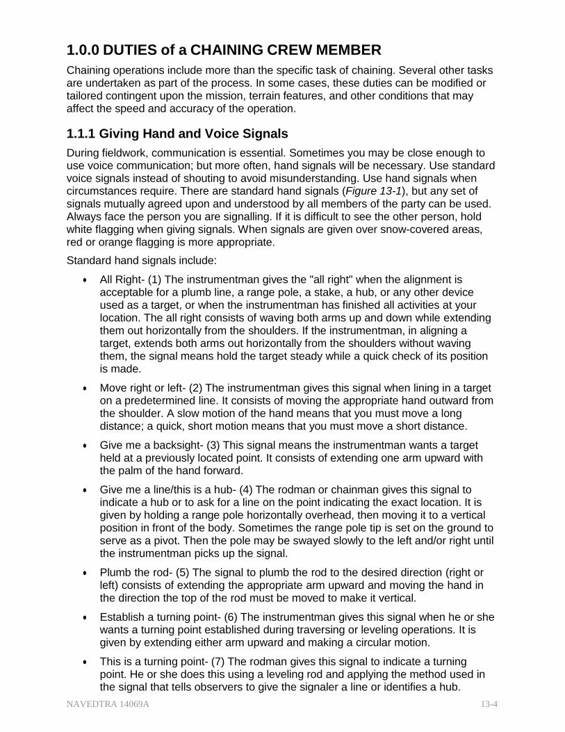
NAVEDTRA 14069A 13-4
1.0.0 DUTIES of a CHAINING CREW MEMBER
Chaining operations include more than the specific task of chaining. Several other tasks are undertaken as part of the process. In some cases, these duties can be modified or tailored contingent upon the mission, terrain features, and other conditions that may affect the speed and accuracy of the operation.
1.1.1 Giving Hand and Voice Signals
During fieldwork, communication is essential. Sometimes you may be close enough to use voice communication; but more often, hand signals will be necessary. Use standard voice signals instead of shouting to avoid misunderstanding. Use hand signals when circumstances require. There are standard hand signals (Figure 13-1), but any set of signals mutually agreed upon and understood by all members of the party can be used. Always face the person you are signalling. If it is difficult to see the other person, hold white flagging when giving signals. When signals are given over snow-covered areas, red or orange flagging is more appropriate.
Standard hand signals include:
All Right- (1) The instrumentman gives the "all right" when the alignment is acceptable for a plumb line, a range pole, a stake, a hub, or any other device used as a target, or when the instrumentman has finished all activities at your location. The all right consists of waving both arms up and down while extending them out horizontally from the shoulders. If the instrumentman, in aligning a target, extends both arms out horizontally from the shoulders without waving them, the signal means hold the target steady while a quick check of its position is made.
Move right or left- (2) The instrumentman gives this signal when lining in a target on a predetermined line. It consists of moving the appropriate hand outward from the shoulder. A slow motion of the hand means that you must move a long distance; a quick, short motion means that you must move a short distance.
Give me a backsight- (3) This signal means the instrumentman wants a target held at a previously located point. It consists of extending one arm upward with the palm of the hand forward.
Give me a line/this is a hub- (4) The rodman or chainman gives this signal to indicate a hub or to ask for a line on the point indicating the exact location. It is given by holding a range pole horizontally overhead, then moving it to a vertical position in front of the body. Sometimes the range pole tip is set on the ground to serve as a pivot. Then the pole may be swayed slowly to the left and/or right until the instrumentman picks up the signal.
Plumb the rod- (5) The signal to plumb the rod to the desired direction (right or left) consists of extending the appropriate arm upward and moving the hand in the direction the top of the rod must be moved to make it vertical.
Establish a turning point- (6) The instrumentman gives this signal when he or she wants a turning point established during traversing or leveling operations. It is given by extending either arm upward and making a circular motion.
This is a turning point- (7) The rodman gives this signal to indicate a turning point. He or she does this using a leveling rod and applying the method used in the signal that tells observers to give the signaler a line or identifies a hub.
NAVEDTRA 14069A 13-5
Wave the rod- (8) This signal, which the instrumentman gives to the rodman, is important to get the lowest stadia reading. The instrumentman extends one arm upward, palm of the hand forward, and waves the arm slowly from side to side. The rodman then moves the top of the leveling rod forward and backward slowly about a foot each way from the vertical.
Face the rod- (9) To give this signal, the instrumentman extends both arms upward to indicate to the rodman that the leveling rod is facing in the wrong direction.
Reverse the rod- (10) The instrumentman gives this signal by holding one arm upward and the other downward, and then reversing their positions with full sidearm swings.
Boost the rod- (11) The instrumentman gives this signal by swinging both arms forward and upward, palms up. The instrumentman uses this signal when he or she wants the leveling rod raised and held with its bottom end at a specified distance, usually about three feet, above the ground.
Move forward- (12) The instrumentman gives this signal by extending both arms out horizontally from the shoulders, palms up, then swinging the forearms upward.
Move back- (13) The instrumentman gives this signal by extending one arm out horizontally from the shoulder, hand and forearm extended vertically, and moving the hand and forearm outward until the whole arm is extended horizontally.
Up or down- (14) The instrumentman gives this signal by extending one arm out horizontally from the shoulder and moving it upward or downward. This directs the rodman to slide the target up or down on the rod.
Pick up the instrument- (15) The party chief gives this signal by imitating the motions of picking up an instrument and putting it on the shoulder. The party chief or other responsible party member gives this signal, directing the instrumentman to move forward to the point that has just been established.
Come in- The chief of party gives this signal at the end of the day's work and at other times, as necessary.
Raise for red- The instrumentman gives this signal in a leveling operation to ascertain the immediate whole-foot mark after reading the tenths and hundredths of a foot. This usually happens when the rodman is near the instrument or if something is in the way and obscures the whole-foot mark.
Extend the rod- The instrumentman gives this signal when there is a need to extend an adjustable rod. This happens when the height of the instrument becomes greater than the standard length of the non-extended adjustable level rod.
Signals for numerals- Left arm extended diagonally up and out from the left shoulder shows a simple system for numerals (Figure 13-2):
o One- Right arm extended diagonally down to the right from the body
o Two- Right arm extended straight out from the body
o Three- Right arm extended diagonally up and out from the right shoulder
o Four- Left arm extended diagonally up and out from the left shoulder

NAVEDTRA 14069A 13-6
o Five- Left arm extended straight out from the body
o Six- Left arm extended diagonally down to the left from the body
o Seven- Both arms extended diagonally down and out from the body
o Eight- both arms extended strait out from the body
o Nine- Both arms extended diagonally up and out from the body
o Zero- Hitting the top of the head with an up and down motion of the palm
Indicate a decimal point using a signal that is easily distinguishable from the other signals. Ensure that you can see both the left and right side of your signalman for numeral signals one through six. Use numeral signals only when it is absolutely necessary. Numeral signals are often misinterpreted, which results in mistakes.
Always use hand signals consistently, and ensure that all survey team members are completely familiar with them.
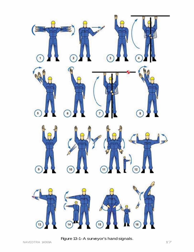
(
NAVEDTRA 14069A Figure 13-1- A surveyor's hand signals.
17
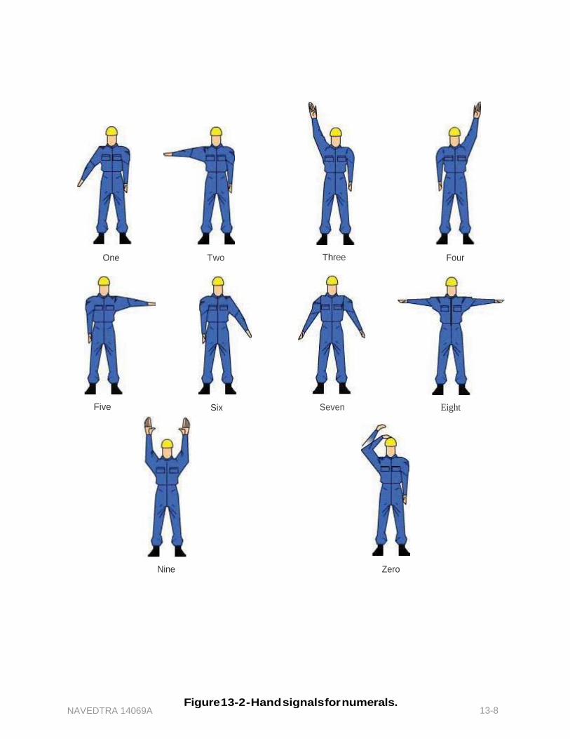
NAVEDTRA 14069A 13-8
One
Five
Nine
Two Three
Six Seven
Zero
Four
Eight
Figure 13-2 - Hand signals for numerals.
NAVEDTRA 14069A 13-9
1.2.0 Clearing the Line
A crew must clear a line ahead when chaining (or taping) across brush-covered country. They must use specific tools, such as those presented in EA Basic; Chapter 12, Elements of Surveying and Survey Equipment, for the kinds of job assigned and handle them with care. Before you start to swing, make sure that no one is within range.
You may cut ordinary scrub growth in unsettled areas more or less as needed. If, however, you encounter large trees or shrubs that may be of value, consult your party chief for advice. Even though a tree or shrub lies directly on the chaining line, it is never absolutely necessary to cut it down. If preserving the tree or shrub is desirable, you can always triangulate around it or bypass it by some other method, as described later in this chapter.
The principle technical problem in clearing the line is keeping on the line. When possible, this is accomplished with natural foresights, that is, bearings taken on natural or artificial objects lying ahead.
If there is no distinctive object lying on the line of bearing ahead, keep the line by blazing ahead. Set up the compass and sight ahead on a tree lying as far ahead as possible. Blaze that tree (using red or white flagging as a marker is also an acceptable method for marking), then clear a line toward the tree.
If growth is too high and thick for a sight to be made, work ahead by looking back and aligning on a couple of markers on the line already covered.
1.3.1 Giving Backsights and Foresights
To run a line by instrument from a point of known location to point B, for example, and given a distance and direction ahead, the instrumentman usually proceeds with the following:
1. Setting up the instrument (usually a transit) over point A
2. Training the telescope on the given direction of the line to B
3. Sighting through the telescope to keep the chainmen on the line for as many consecutive foresights as can be observed from that particular instrument set up
If the chainmen are using a 100-foot tape, and have trained the instrument along the line of direction, the head chainman walks away with the zero-foot end of the tape, while the rear chainman holds the 100-foot end on the point plumbed by the instrument. After the head chaiman has walked out the whole 100 feet, a plumb bob is dropped on a cord from the zero-foot mark to the ground.
The instrumentman sights along the line and thus determines the direction in which the head chainman must move to bring the plumb bomb onto the line. The "move right" or "move left" signal is given if needed. When the head chainman has been brought by signal to the vicinity of the line, the instrumentman signals for the final placement of the plumb bob by calling out, "To you!" (Meaning "Move the plumb bob toward yourself!") or "Away!" (Meaning, "Move the plumb bob away from yourself!").
When the plumb bob is exactly on the line, the instrument man calls out, "Good!" or "All right!" The head chainman then marks the point indicated by the plumb bob in the correct manner. The first 100 feet is then considered measured on the given line of direction.
NAVEDTRA 14069A 13-10
If the distance to be measured is long, the chainmen will eventually proceed beyond the scope of the instrument as it is then set up. The instrumentman must shift the instrument ahead to the last point marked by the head chainman. When the instrument has been set up over this point, the instrumentman must reorient the telescope to the line of direction. To do this, he or she usually plunges the telescope (rotates it vertically) and backlights on a point on the line already laid off. In taking backlights, the instrumentman is guided by the rear chainman who holds on, or plumbs over, the point. When the telescope has been trained on the backsight point, it is again plunged. The telescope is trained in the desired direction.
1.3.1 Holding on a Point
Figure 13-3 – Short sight
indicators.
If the chainman can site the point on the ground through the telescope, he or she may simply hold on the point; that is, hold a pencil point, chaining pin point, plumb bob point, or some other appropriate indicator on the point (Figure 13-3). Whatever the indicator may be, it is essential to hold it in an exactly vertical position. For short sights, it is also essential that the shaft of the indicator be relatively slender so that the vertical cross hair can be aligned with sufficient exactness.
1.3.2 ver a Point
If intervening low growth or some other circumstance makes sighting the point on the ground impossible for the instrumentman, the chainman must plumb over the point, using the plumb bob and cord. If the distance is too far for observation of the plumb bob cord, the cord should be equipped with a plumb bob target, or you may use a range pole. In the absence of a target when using the plumb bob, you may tie a piece of colored flagging to the cord or use a handkerchief (Figure 13-4).
Figure 13-4 – Target substitution.
NAVEDTRA 14069A 13-11
Some chainmen prefer to hold the plumb bob and cord with the cord running over the forefinger. Others prefer to run the cord over their thumb. If you are plumbing high (that is, required to hold the cord at chest level or above), learn to brace your holding arm with your other arm, and against your body or head or both, to avoid unsteadiness and fatigue. When there is wind, you may find it difficult to hold the plumb bob suspended over a point. It will tend to swing back and forth. You can overcome this problem by bouncing the point of the plumb bob slightly up and down on the point.
For a long sight, it is much better to plumb over a point with a range pole. For a short sight, however, the shaft of a range pole is too thick to permit exact alignment of the vertical cross hair. For long sights, or for sights on a point that is to be sighted
Figure 13-5 – Semi-permanent targets.
repeatedly, constructing a semi-permanent target is often desirable. There are no definite rules for constructing targets because they are typically built from materials at hand. Use your ingenuity to ensure that the target is high enough to be seen, strong enough to withstand prevailing winds, and is plumbed over a point (Figure 13-5).
1.4.0 Marking Control Points, Reference Points, and Monuments
In general, control surveys deal with established points. To define these points, surveyors have to mark them. Certain points are made permanent, and others are temporary. A long term line, for example, may be marked at each end with a bronze disk set in concrete, or with a center-punched metal rod driven flush with the ground. For less permanent control points, wooden stakes or hubs with nails, shiners, and floggings are typically used.
1.4.1 Placing Driven Markers
Always set a driven marker exactly vertically on the point it is supposed to mark. If you drive it on a slant, the top of the marker will not define the correct location of the point. To drive the marker vertically, first align it vertically; then, using a sledgehammer or other type of driving implement, strike each blow squarely on the flat end of the hub or stake.
You will normally drive a wooden hub to mark the exact horizontal location of a point, usually for the purpose of plumbing an instrument over the point. Consequently, the top of a hub (or other markers used for the same purpose) will not normally need to extend much above the ground line. Mark the precise location of the point is marked by a hub tack, punch mark, or other precise marker driven or set in the top of the hub. For work on asphalt roads or runways, you'll find it easier to use flagging or a soda pop top and a nail as a marker; in concrete and other hard surfaces, you can use orange paint or a star-drilled hole plugged with lead. The choice of markers depends on the surveyor's judgment as well as the purpose of the survey. In frozen or otherwise extra hard ground, use a bull-point to start a hole for a stake or hub. Remember that the stake or hub will
NAVEDTRA 14069A 13-12
follow the line of the opening made by the bull-point. Therefore, if the bull-point is not driven vertically, the stake or hub will not be vertical either.
1.4.2 lacing Monuments
In surveying, a monument is a permanent object or structure used where a point or station must be retained indefinitely for future reference. It may simply consist of a conspicuous point carved on an outcrop of a ledge rock or it may be constructed in concrete (Figure 13-6). The top of the monument should have an area large enough to include the required point and any necessary reference data. The depth of the monument should be sufficient to extend below the frost line. If the depth of the frost line is unknown, a minimum depth of three feet is generally accepted. Other factors, such as soil condition and stability of foundation, may also affect the depth of the monuments. Check the area for soil stability to provide an adequate foundation. A monument settles in the same manner as any other structure if it does not have an adequate foundation.
Figure 13-6 – Common types of survey monuments.
Mark the exact location of the point on a monument by chiseling an "X" on the surface or by drilling a hole with a star drill and hammering in a lead filler or grouting in a length of brass stock (often called a copper). When grouting a copper, use neat cement grout because a fluid grout would flow into and fill the small space around the copper. If the point can be placed at the same time as the casting of the monument, the copper can be pushed down into the surface of the monument before the concrete begins to harden. If you are near an armory, you may be able to obtain large, expended brass shell casings. The primer end of a shell casing makes an excellent survey point marker when it is embedded in a concrete monument. With a little imagination and ingenuity, you can easily design and construct adequate survey monuments.
1.4.3 Identifying Points
Mark a point with identification information and any additional relevant data. You can make temporary identification marks with keel and more permanent ones with paint. An even more permanent mark consists of a metal plate set in concrete. Mark a point that indicates a traverse station with the symbol or number of the station, such as "STA. B" or "STA. 21". Mark a point on a stationed traverse with the particular station, such as 2 +
NAVEDTRA 14069A 13-13
87.08. Frequently, a point will serve as a traverse station and a bench mark. A bench mark is marked with an identifying symbol and usually the elevation. In marking such an elevation, do not use a decimal point, as in 317.22 feet. Instead, raise the figures that indicate the fractional part and underline them.
1.4.4 Referencing Points
Tie in or reference all control points. Record the ties or reference points in the field book as you establish them in the field. The record may be made by sketch, work description, or the combination of the sketch and notes. You must reference the control point to some permanent type of object in its vicinity; if no such objects exist, drive reference hubs at points where they are unlikely to be disturbed. These ties are important in recovering control points that have been covered or otherwise hidden or in reestablishing them accurately if they have been removed.
Record the reference location of a particular point on the remarks page of the field book (Figure 13-7 and 13-8). For a permanent control point, such as a triangulation point, monument, or bench mark, prepare a complete station description individually for each station. The field offices of the National Oceanic and Atmospheric Administration or the National Geological Survey have these station descriptions on separate cards. They do this so they can easily run a copy for anyone requesting a description of a particular station. They also maintain a vicinity map on which these points are plotted, and these station descriptions are used in conjunction with this map. The Navy's public works offices also maintain descriptions of stations within their naval reservation and its vicinity for immediate reference.
Figure 13-7 – Natural and man-
made reference points.
Figure 13-8 – Accurate methods
for tying points.
Referencing points are ideal for recovering points that have been covered or otherwise hidden and reestablishing points accurately.
As you gain more experience, you may be assigned the task of writing a station description. When writing a station description, be sure to describe the location in detail, and make a sketch showing the location, ties, as well as magnetic or true meridian. Make your description concise and clear, and be sure to test its effectiveness by letting another EA (preferably not a member of the survey party that established the point)
NAVEDTRA 14069A 13-14
interpret your description. From the feedback of the interpretation, you can determine the accuracy of your written description. Your description, for example, should be written as follows (Figure 13-8):
"Point A-plugged G.I. pipe 65.21 ft SE of NE corner of PWC Admin. Bldg. (Bldg. 208) and 81.42 ft from the SE corner of same building. It is 18.18 ft W of the center of a circular manhole cover located in Saratoga Street."
1.4.5 tecting Markers
Protect markers from physical disturbance by erecting a temporary fence (or barricade) around them. Sometimes guard stakes embellished with colored flaggings are simply driven near the hub or similar marker to serve as deterrence against machinery or heavy equipment traffic. Protect permanent markers with fixed barricades, such as steel or concrete casing.
Test your Knowledge (Select the Correct Response)
1. What actions should the rodman take in response to a boost-the-rod signal?
A. Raise the rod and hold it at a specified distance above the ground B. Turn the rod upside down C. Raise the rod slowly until the instrumentman has read the whole-foot mark D. Move the top of the rod in a short arc towards the instrument
2. What term is used to describe consecutive sights taken through a telescope for
the purpose of keeping chainmen on line?
A. Running line B. Bench mark C. Foresight D. Backsight
3. When an important station is marked with a hub, measurements are made to one
or more other points and recorded in a field notebook to assure what information?
A. The hub can be relocated if plowed up and displaced. B. The hub location is precisely determined. C. The reference points are located accurately. D. The elevation of the hub can be determined.
2.0.0 METHODS of DIRECT LINEAR MEASUREMENTS
One of the most fundamental surveying operations is the measurement of horizontal distance between two points on the surface of the earth. Generally, there are two basic methods used: direct and indirect. Direct linear measurements, as explained earlier in this chapter, are methods used for determining horizontal distances with a tape (or chain) and/or with an electronic distance-measuring instrument. Indirect methods to take measurements use the transit and stadia or the theodolite and stadia. This section will discuss the common methods of direct linear measurements.
NAVEDTRA 14069A 13-15
2.1.0 Chaining (Taping)
The most common method used in determining or laying off linear measurements for construction surveys, triangulation base lines, and traverse distances is called chaining. The name is carried over from the early days when surveyors used the Gunter's chain and the engineer's chain. Today, it is more appropriate to call this operation taping because the steel tape has replaced the chain as the surveyor's measuring device. This manual, however, will use chaining and taping interchangeably.
2.1.1 Identifying Duties of Chaining Party Members
The smallest chaining party could consist of only two people-one at each end of the tape. To lay off a line to a desired distance, one person holds the zero end of the tape and advances in the direction of the distant point, while the other holds a whole number of the tape at the starting point. The person ahead, holding the zero end, is the head chainman; the other person is the rear chainman. In ordinary chaining operations, if the distance being measured is greater than a tape length, it is necessary to mark the terminal point with a range pole. In this way, the rear chainman can keep the head chainman aligned at all times whenever a full tape length or a portion of it is transferred to the ground. The head chainman also acts as the recorder, and the rear chainman is responsible for keeping the tape in alignment. If more speed or precision in taping is required, additional personnel are assigned to the party. This relieves the chainmen of some of their duties and permits them to concentrate primarily on the measurement. For more precise chaining, a three-man party is essential. In addition to the head and rear chainmen, a stretcherman is part of a three-man party. The duties of the stretcherman are to apply and maintain the correct tension on the tape while the chainmen do the measuring. The head chainman still acts as the recorder and reads and records the temperature of the tape.
Either of the two chaining parties described may have additional personnel assigned as follows:
A recorder keeps a complete record of all measurements made by the taping party, makes any sketches necessary, writes descriptions of stations and reference points, and records any other data required. The head chainman or the chief of the chaining party may perform these duties.
A rodman sets a range pole at the forward station to define the line to be taped, drives stakes to mark stations and reference points, carries the taping stool to the forward point, and performs other duties as directed.
One or more axmen clear lines of sight between stations, cut and drive stakes, and perform other duties as directed.
The chief of the chaining party directs the work of making the tape measurements, the establishment of stations, and other activities of the party in the field. The head chainman performs these duties when there is no separate party chief.
2.1.2 and Throwing a Steel Tape
Tapes generally come equipped with a reel; however, it is not always necessary to replace a steel tape on the reel at the end of each work period. A tape can be easily coiled and thrown into a circular roll.
Grasp the 100 foot graduation on the tape face with your left hand. Using your right hand, take in five feet of tape at a time. Place the 95 foot mark over the 100 foot mark,
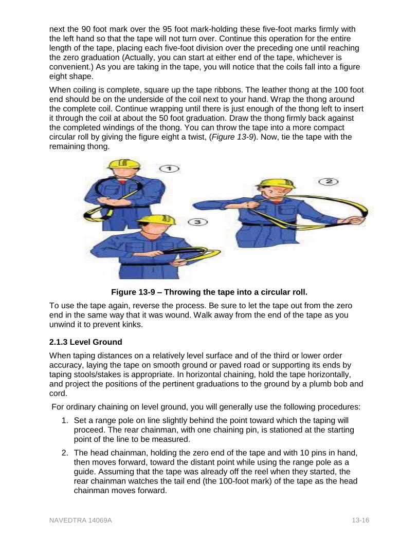
NAVEDTRA 14069A 13-16
next the 90 foot mark over the 95 foot mark-holding these five-foot marks firmly with the left hand so that the tape will not turn over. Continue this operation for the entire length of the tape, placing each five-foot division over the preceding one until reaching the zero graduation (Actually, you can start at either end of the tape, whichever is convenient.) As you are taking in the tape, you will notice that the coils fall into a figure eight shape.
When coiling is complete, square up the tape ribbons. The leather thong at the 100 foot end should be on the underside of the coil next to your hand. Wrap the thong around the complete coil. Continue wrapping until there is just enough of the thong left to insert it through the coil at about the 50 foot graduation. Draw the thong firmly back against the completed windings of the thong. You can throw the tape into a more compact circular roll by giving the figure eight a twist, (Figure 13-9). Now, tie the tape with the remaining thong.
Figure 13-9 – Throwing the tape into a circular roll.
To use the tape again, reverse the process. Be sure to let the tape out from the zero end in the same way that it was wound. Walk away from the end of the tape as you unwind it to prevent kinks.
2.1.3 Level Ground
When taping distances on a relatively level surface and of the third or lower order accuracy, laying the tape on smooth ground or paved road or supporting its ends by taping stools/stakes is appropriate. In horizontal chaining, hold the tape horizontally, and project the positions of the pertinent graduations to the ground by a plumb bob and cord.
For ordinary chaining on level ground, you will generally use the following procedures:
1. Set a range pole on line slightly behind the point toward which the taping will proceed. The rear chainman, with one chaining pin, is stationed at the starting point of the line to be measured.
2. The head chainman, holding the zero end of the tape and with 10 pins in hand, then moves forward, toward the distant point while using the range pole as a guide. Assuming that the tape was already off the reel when they started, the rear chainman watches the tail end (the 100-foot mark) of the tape as the head chainman moves forward.
NAVEDTRA 14069A 13-17
3. When the rear chainman sees that the tail end is about to reach position, he or she uses the verbal cue, "Chain!" to solicit the head chainman to stop and look back. The rear chainman holds the 100 foot mark at the starting point and checks the alignment; then signals the way the head chainman should move to bring the chaining pin in line. While doing this, they are both in a kneeling position, the rear chainman facing the distant point, and the head chainman to one side facing the line so that the rear chainman has a clear view of the range pole. The head chainman, while stretching the tape with one hand, sets the pin vertically on line a short distance past the zero mark with the other hand. Then by pulling the tape taut and making sure that the tape is straight, the head chainman brings it in contact with the pin, while the rear chainman, watching carefully for the 100 foot mark to be exactly on the point calls, "All right '. At this point, the head chainman relocates the pin to exactly the zero mark of the tape and places it sloping away from the line. The head chainman pulls on the tape again to make sure that the zero mark really matches the point where the pin is stuck in the ground and calls "All right" or "Stuck". This is a signal to the rear chainman to release the tape so he can continue forward for the next measurement. The chainmen repeat this process until the entire distance is measured.
4. As the rear chainman moves forward, the pin is pulled from the point. Thus, there is always one pin stuck in the ground, and the number of pins in possession indicates the number of 100 foot (stations) tape lengths they have measured from the starting point to the pin in the ground.
Every time the head chainman runs out of pins, the rear chainman comes forward, and both of them count the pins in the rear chainman's possession. There should be 10 pins.
2.1.3.1 Supporting the Tape
When a full tape length is measured, two chainmen support the ends. The tape may be laid on a level ground surface, such as a paved road or railroad rail, or suspended between stools or bucks set under the ends of the tape. For precise measurement, such as a base line measurement, the tape is supported at midpoint or even at quarter points by bucks or stakes.
In horizontal taping over sloping or irregular terrain, one end of the tape is held on the point at ground level, while the other end is supported high enough to make the tape horizontal. The rear chainman holds a full graduation of the tape at the point near the ground, and the head chainman, holding the zero end, projects the desired distance to the point on the ground by using the plumb bob (Figure 13-10).
NAVEDTRA 14069A 13-18
Figure 13-10 – Horizontal taping on a slope. 2.1.3.2 Aligning the Tape
Any misalignment of the tape, either horizontally or vertically, will result in an error in the measurement. Misalignment always results in a recorded distance that is too long, or a laid offline that is too short. This is obvious, since the shortest distance between two points is a straight line. Keep the tape straight and level at all times.
2.1.3.3 Applying Tension
A tape supported or held only at the ends will hang in the shape of a curve, called a catenary. Depending on the tension or pull applied at the ends, this catenary will become shallower or deeper, and the distance between the supported ends will vary considerably. To standardize this distance, apply a recommended "standard" tension when you are measuring. Attach a spring balance or tension handle to one end of the tape and measure the correct standard tension. The amount of standard tension is discussed later under "Making Tape Corrections". Maintaining a constant tension for any length of time by a hand pull is uncomfortable and can be erratic. For easier chaining, each chainman uses a pole or rod from one half inch to two inches in diameter, and about six feet long. The leather thong attached to the tension handle is wrapped around the pole at the proper height. The chainman braces the bottom end of the pole against the outside of his or her foot and applies tension by bracing his or her shoulder against the pole and shifting his or her body weight until the correct tension reads on the scale. This position can be held steadily and comfortably for a comparatively long time.
Measuring distances less than a full tape length requires the clamp handle (or "scissors clamp"), which is attached to the tape at some convenient point along its length. The handle permits a firm hold on the tape and furnishes a convenient attachment for a spring balance. When properly used, the handle will prevent the tape from kinking.
2.1.3.4 Reading the Tape
A chain tape may be either a plus (or add) tape, or a minus (or subtract) tape. On a plus tape, the end foot, graduated in subdivisions, is an extra foot, lying outside the zero foot mark on the tape and graduated away from the zero foot mark. On a minus tape, the end foot, graduated in subdivisions, is the foot lying between the zero foot mark and one
NAVEDTRA 14069A 13-19
foot mark and graduated away from the zero foot mark and toward the one foot mark. This difference is significant for measuring a distance of less than a full tape length.
Suppose that you are measuring the distance between point A and point B with a 100 foot tape, and the distance is less than 100 feet. Suppose that you are the head chainman. To start, you and the rear chainman are both at point A. You walk away from point A with the zero-foot end of the tape. Because this is a plus tape, the tape has an extra foot beyond the zero-foot end, and this foot is subdivided into hundredths of a foot, reading from the zero.
You set the zero on point B, or plumb it over point B then call out, "Take a foot". The rear chainman then pulls back the first even foot graduation between A and B to point A, or plumbs it over point A. As an example, if this is a 34 foot graduation, the rear chainman will call out "thirty-four". Now read the subdivided end foot graduation that is on or over point B. Let's say it is the 0.82 foot graduation. You call out, "Point eight two '. The rear chainman rechecks the even-foot graduation on point A and calls out, "Thirty- four point eight two". As you can see, your subdivided foot reading is added to his even foot reading; hence, the expression "plus" tape. Suppose now that you are measuring the same distance between the same points, but using a "minus" tape, that is, a tape on which the subdivided end foot lies between the zero-foot and one foot graduations. This time when you walk away with the zero-foot end, you set the one foot graduation on point B and call out, "take a foot". The rear chainman then hauls back the first even-foot graduation between A and B to point A but this time on the 35 foot graduation so the rear chainman calls out, "thirty-five", which is your cue to read the subdivided foot graduation on point B. This time it is the 0.18 foot graduation, so you call out, "Minus point one eight". The rear chainman mentally subtracts the 0.18 foot from 35.00 feet and calls out, "Thirty-four point eight two". When you are also acting as the recorder, be sure to recheck the subtraction before you record the distance in the field notebook.
2.1.3.5 Giving a Line
The range pole is set on line slightly behind the point toward which the taping will proceed. Line may be given (that is, the person with the range pole may be guided or signaled onto the line) by "eyeball" (that is, by eye-observation alignment by the rear chainman or someone else at the point from which chaining is proceeding) or by instrument.
2.1.4 Chaining
The methods used in slope chaining are similar to those used in chaining on level ground, though there are some minor differences. In slope chaining, the tape is held along the slope of the ground, the slope distance is measured, and the slope distance is converted, by computation, to horizontal distance. The slope angle is usually measured with an Abney hand level and clinometer; however, for precise measurement, it is measured with a transit.
In using the clinometer, take the slope angle along a line parallel to the slope of the ground or along the tape that is held taut and parallel to the slope of the ground. To use the clinometer, sight on an object that is usually a point on a pole approximately equal to your Height of Instrument (HI); that is, the vertical distance from the ground to the center (horizontal axis) of the sight tube. While sighting the object, rotate the level tube about the axis of vertical arc until the cross hairs bisect the bubble as you look through the eyepiece. Then, read either the slope angle or percentage on the vertical arc and record it along with the slope distance measurement. Compute the horizontal distance, or in other words, apply the tape correction. If you are marking the station points, apply
NAVEDTRA 14069A 13-20
the corrections to the slope distances as the chaining progresses. Compute these corrections mentally, by calculator, or by using a table.
If the ground slope is fairly uniform, and if the tape corrections do not exceed one foot, a plus 100 foot tape is very useful to establish these station points. The head chainman determines the slope correction first, and then lays off the true slope distance that gives a horizontal distance of 100 feet. If the slope is less than two percent, no slope correction is required. Slope corrections are discussed later in this chapter.
2.1.5 Horizontal Chaining
In horizontal chaining, the tape is supported only at its ends and held in a horizontal position. Plumb bobs are used to project the end graduations of the tape (or, for a less- than-tape length measurement, an end and an intermediate graduation) to the ground. Be very careful when you use the plumb bob both in exerting a steady pull on the tape and in determining when the tape is horizontal.
2.1.5.1 Plumbing
Plumbing is complete when the tape is in horizontal alignment and under the proper tension. The rear chainman holds a plumb bob cord at the proper graduation of the tape, and the point of the plumb bob about one-eighth of an inch above the marker from which the measurement is being made. When the plumb bob is directly over the marker, the rear chainman calls, "mark".
The head chainman holds a plumb bob cord at the correct graduation of the tape with the point of the plumb bob about one inch above the ground. He or she allows the plumb bob to come to rest; sees that the tape is horizontal; checks its alignment and tension; and when the rear chainman calls, allows the plumb bob to fall and stick in the ground. This spot is then marked with a chaining pin.
At times, in rough country, a small area around the point may require clearing for dropping the plumb bob. Because the clearing is usually done by kicking away small growth, this type of clearing is commonly called a kickout. To determine the approximate location of the kickout, the head chainman may call, "line for kickout" and then "distance for kickout". At "Line for kickout", the rear chainman or instrumentman gives the approximate line by eyeball. At "distance for kickout", the rear chainman holds approximately over the starting point without being too particular about plumbing.
2.1.5.2 Leveling the Tape
To make the tape level when two chainmen are making a horizontal measurement on a slope, the person at the lower level is holding the end at chest level while the person at the higher level is holding it at knee level (Figure 13-11). To maintain the tape in a horizontal position, the chainman at the lower level holds the hand level. By studying the position of the other chainman, he or she decides that it would be possible to hold the tape at chest level. The chainman at the lower level then holds the hand level at about the height of his or her own chest level and trains it on the other chainman. It indicates that a level line from his or her own chest level intersects the person of the other chainman at that person's knee level, and so calls out, "at your knee" thus informing the other chainman where to hold the end of the tape.
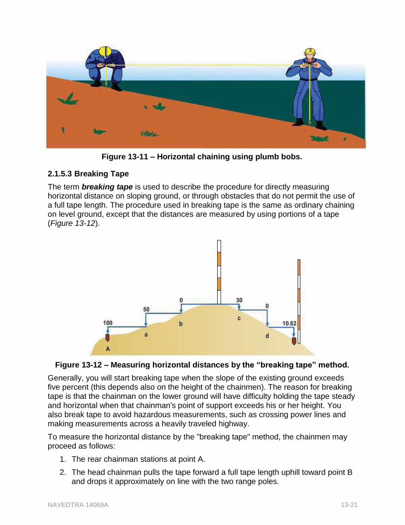
NAVEDTRA 14069A 13-21
Figure 13-11 – Horizontal chaining using plumb bobs.
2.1.5.3 Breaking Tape
The term breaking tape is used to describe the procedure for directly measuring horizontal distance on sloping ground, or through obstacles that do not permit the use of a full tape length. The procedure used in breaking tape is the same as ordinary chaining on level ground, except that the distances are measured by using portions of a tape (Figure 13-12).
Figure 13-12 – Measuring horizontal distances by the “breaking tape” method.
Generally, you will start breaking tape when the slope of the existing ground exceeds five percent (this depends also on the height of the chainmen). The reason for breaking tape is that the chainman on the lower ground will have difficulty holding the tape steady and horizontal when that chainman's point of support exceeds his or her height. You also break tape to avoid hazardous measurements, such as crossing power lines and making measurements across a heavily traveled highway.
To measure the horizontal distance by the "breaking tape" method, the chainmen may proceed as follows:
1. The rear chainman stations at point A.
2. The head chainman pulls the tape forward a full tape length uphill toward point B and drops it approximately on line with the two range poles.
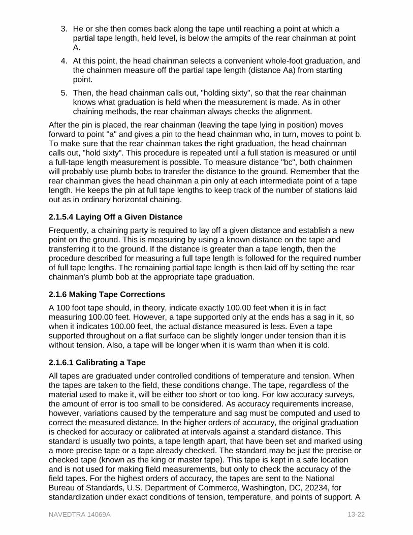
NAVEDTRA 14069A 13-22
3. He or she then comes back along the tape until reaching a point at which a partial tape length, held level, is below the armpits of the rear chainman at point A.
4. At this point, the head chainman selects a convenient whole-foot graduation, and the chainmen measure off the partial tape length (distance Aa) from starting point.
5. Then, the head chainman calls out, "holding sixty", so that the rear chainman knows what graduation is held when the measurement is made. As in other chaining methods, the rear chainman always checks the alignment.
After the pin is placed, the rear chainman (leaving the tape lying in position) moves forward to point "a" and gives a pin to the head chainman who, in turn, moves to point b. To make sure that the rear chainman takes the right graduation, the head chainman calls out, "hold sixty". This procedure is repeated until a full station is measured or until a full-tape length measurement is possible. To measure distance "bc", both chainmen will probably use plumb bobs to transfer the distance to the ground. Remember that the rear chainman gives the head chainman a pin only at each intermediate point of a tape length. He keeps the pin at full tape lengths to keep track of the number of stations laid out as in ordinary horizontal chaining.
2.1.5.4 Laying Off a Given Distance
Frequently, a chaining party is required to lay off a given distance and establish a new point on the ground. This is measuring by using a known distance on the tape and transferring it to the ground. If the distance is greater than a tape length, then the procedure described for measuring a full tape length is followed for the required number of full tape lengths. The remaining partial tape length is then laid off by setting the rear chainman's plumb bob at the appropriate tape graduation.
2.1.6 Making Tape Corrections
A 100 foot tape should, in theory, indicate exactly 100.00 feet when it is in fact measuring 100.00 feet. However, a tape supported only at the ends has a sag in it, so when it indicates 100.00 feet, the actual distance measured is less. Even a tape supported throughout on a flat surface can be slightly longer under tension than it is without tension. Also, a tape will be longer when it is warm than when it is cold.
2.1.6.1 Calibrating a Tape
All tapes are graduated under controlled conditions of temperature and tension. When the tapes are taken to the field, these conditions change. The tape, regardless of the material used to make it, will be either too short or too long. For low accuracy surveys, the amount of error is too small to be considered. As accuracy requirements increase, however, variations caused by the temperature and sag must be computed and used to correct the measured distance. In the higher orders of accuracy, the original graduation is checked for accuracy or calibrated at intervals against a standard distance. This standard is usually two points, a tape length apart, that have been set and marked using a more precise tape or a tape already checked. The standard may be just the precise or checked tape (known as the king or master tape). This tape is kept in a safe location and is not used for making field measurements, but only to check the accuracy of the field tapes. For the highest orders of accuracy, the tapes are sent to the National Bureau of Standards, U.S. Department of Commerce, Washington, DC, 20234, for standardization under exact conditions of tension, temperature, and points of support. A
NAVEDTRA 14069A 13-23
tape standardization certificate is issued for each tape, showing the amount of error under the different support conditions and the coefficient of expansion. The certificate (or a copy) is kept with each tape. For field operations, the tapes are combined in sets; one is selected as the king tape, while the others are used as field tapes.
The standard tension for a tape supported throughout is 10 pounds, and the standard temperature is 68 degrees Fahrenheit. Standard length is, simply, the nominal length of the tape. A 100 foot tape, for example, at a temperature of 68°F, supported throughout, and subject to a tension of 10 pounds, should indicate 100 feet when it is measuring exactly 100 feet. To calibrate a 100 foot tape means to determine the exact distance it is actually measuring when it indicates 100 feet, while being supported throughout, at a temperature of 68°F and under a tension of 10 pounds. In addition to the National Bureau of Standards, many state and municipal authorities provide standardizing service.
2.1.6.2 Recognizing Tape or Standard Error
Suppose now that you send a 100 foot tape to the Bureau of Standards to be calibrated; the bureau will return a certificate with the tape. Assume that the certificate states that when the tape, supported throughout at a temperature of 68°F, and under a tension of 10 pounds, indicates 100 feet, it actually measures 100.003 feet on the standard tape. The tape, then, has a standard error (also called tape error) of 0.003 feet for every 100 feet it measures. This tape "reads short." Depending on the order of precision of the survey, you may have to apply this as a correction to measurements made with this particular tape.
2.1.6.3 Correcting for Standard Error
Whether you add or subtract, the standard error depends upon the direction of the error. The tape in the previous example indicates a distance that is shorter than it actually measures; in other words, when you use this tape to lay off a distance of 100 feet, the line is actually 100.003 feet. The decision to add or subtract the error depends upon whether you are measuring to determine the distance between two points or to set a point at a given distance from another. Assume first that you're measuring the distance between two given points, and the distance as indicated by the tape is 362.73 feet.
The total tape error is 0.003 times the number of tape lengths. In this case, it is 0.003 x 3.6273 = 0.0108819 feet, which rounds off to 0.01 foot.
Then add the tape error. The correct distance between the two points, then, is 362.74 feet. Suppose now that with the same tape, you are to set a point 362.73 feet away from another point. Your correction here will be applied in the opposite direction. Since the tape reads short, the laid tape distance of 362.73 feet is longer than 362.73 feet by the amount of the total correction for standard error (0.01 foot). Therefore, you must subtract the total tape error. To lay off a distance of 362.73 feet with this tape, measure off a distance of 362.72 feet.
Suppose now that the Bureau of Standards calibration certificate states that when a tape indicates 100.00 feet under standard conditions, it is actually measuring only 99.997 feet. Again, the standard error is 0.003 feet per 100 feet, but this tape "reads long"; that is, the interval it indicates is longer than the interval it is actually measuring. Suppose you measure the distance between two given points with the tape and find that the tape indicates 362.73 feet. The total standard error is still 0.01 feet. Because the tape reads long, however, the distance it indicates is longer than the distance it actually
NAVEDTRA 14069A 13-24
measures. Therefore subtract the total standard error and record the distance between the given points at 362.72 feet.
Suppose you are using this same tape to set a point 362.73 feet away from another point. Again, the total standard error is 0.01 feet. Because the tape reads long, however, a measurement of 362.73 feet by the tape will actually be less than 362.73 feet. Therefore, add the total correction for standard error, and measure off 362.74 feet by the tape.
2.1.6.4 Correcting for Temperature Variation
Take a 100 foot steel tape that has been calibrated at a standard temperature of 68°F. The coefficient of thermal expansion of steel is about 0.0000065 units per 1°F. The steel tape becomes longer when its temperature is higher than the standard and shortens the same amount when it is colder. The general formula for variation in temperature correction is as follows:
Ct = 0.0000065(T- To)
Where
Ct = Correction for expansion or contraction caused by variation in temperature.
L =Tape calibrated length
To = Standard temperature (usually 68°F)
T = Temperature during measurement
From the above formula, you can deduce that the correction for a 100 foot tape is about 0.00065 feet per 1°F, which is about 0.01 feet for every 15°F change in temperature above or below the standard temperature of 68°F. The temperature correction applies in the same manner and direction as the standard tape error. If the tape measurement is taken at a higher temperature than standard, the tape will expand and read short; naturally the correction should be added. The error caused by variation in temperature is greatly reduced when an Invar tape is used.
2.1.6.5 Correcting for Sag
Even under standard tension, a tape supported or held only at the ends will sag in the center, based on its weight per unit length. This sag will cause the recorded distance to be greater than the length being measured. When the tape is supported at its midpoint, the effect of sag in the two sections is considerably less than when the tape is supported only at its ends. As the number of equally spaced intermediate supports increases, the distance between the end graduations will approach the length of the tape when supported throughout its length. The correction for the error caused by the sag between the two supports for any section can be determined by the following equation:
Cs = w 2l 3
24t 2
Where
Cs = Correction for sag (in feet)
w =Weight per unit length of tape (in pounds per foot)
l = The length of the suspended section of tape (in feet)
t = Tension applied to the tape (in pounds)
NAVEDTRA 14069A 13-25
For full tape-length measurements, the correction for sag is usually taken care of by calibrating the tape. The tape must be calibrated regardless of how it is supported and under standard temperatures and tension. To reduce the value of the horizontal correction for sag, the Bureau of Standards suggests standard tensions for tapes supported at only the ends as follows:
100 foot tapes - 20 to 30 pounds
150 foot tapes - 25 to 30 pounds
200 foot tapes - 30 to 40 pounds
Generally, for a heavy 100 foot tape weighing about three pounds that was standardized, whether supported throughout or at the ends only, the systematic error per tape length caused by sag is as follows:
10 pound tension = 0.37 feet
20 pound tension = 0.09 feet
30 pound tension = 0.04 feet
For the Engineering Aid's survey work, measurements are normally in the lower order of precision. The correction for sag varies with the cube of the unsupported length; for short spans, it is often negligible.
2.1.6.6 Correcting for Slope
When you take a measurement with a tape along an inclined plane (along the natural slope of the ground), the taped distance is greater than the horizontal distance.
The difference between the slope distance and the horizontal distance (s - d) is called the slope correction. Always subtract this correction from the slope distance. To compute for the slope correction, you should know either the vertical angle, A, or the difference in elevation, h, between the taped stations.
When you use the vertical angle, the formula for slope correction is as follows:
Ch = s Vers A
Since
then
where
Vers A = (1 - cosA)
Ch = s(1 - cosA)
Ch = The slope distance correction
s = The tape slope distance (usually a tape length)
A = The vertical angle
When you use the difference in elevation, the approximate formula derived by the Pythagorean Theorem of a right triangle for the slope correction (Figure 13-13), for the slope correction is as follows:
h2 = s2 – d2
Figure 13-13 – Correction for slope
distance.
NAVEDTRA 14069A 13-26
h2 = (s + d)(s – d)
s – d = h2
s + d
But for a small slope, d is approximately equal to s; therefore,
s + d = 2d
and since Ch = s – d
Ch = h2
2s
For slopes greater than five percent, a closer approximation of can be determined by expanding the formula to:
h2
Ch 2s
h4
8s
3
2.1.7 reparing Chaining Notes
There are several general, yet important principles applicable to all types of field notes. Recording of accurate measurements and other data is essential, as is inclusion of any additional information required to identify and clarify the data.
Field notes must be legible and accurate. Record all notes in pencil; a 3H or 4H pencil is best for the job. A pencil that is too soft blunts too quickly; one that is too hard makes a faint mark and scores the paper. In the field, carry a pocketknife or pocket pencil sharpener to keep your pencil sharpened.
Erasures are not permitted in field notes. Suppose that in the course of chaining several intervals you make a 10 foot "bust" in one of the intervals by misreading 10 feet as 20 feet. After you total up the distance, some circumstance leads you to suspect that the total is off. You recheck the work and discover where you made the bust. The notebook record for that interval must be changed. Make the change by crossing out the wrong entries and entering the correct ones above them-not by erasing the wrong entries.
2.1.7.1 Recording Notes for Horizontal Chaining
There are typical examples of a horizontal chaining conducted for a closed traverse (Figure 13-14). The chaining party started at station A and chained around by way of B, C, and so on. Arriving back at A, the party reversed its direction and chained back around by way of E, D, C, and so on, as a check. The distance recorded for each traverse line was the mean (average) between the forward measurement and the backward measurement.
NAVEDTRA 14069A 13-27
Figure 13-14 – Notes for horizontal chaining.
Note on the bottom left-hand side of the data page that the tape had a standard error of 0.013 feet per 100 feet of tape. The error is marked " + ", meaning that the amount of error should be added to the measurement as indicated by the tape since the tape was reading short.
The corrections in the "Correction" column indicate that only correction for standard error was made. If corrections for temperature and sag had been made, the algebraic sum of all three would have been entered in the correction column, or additional columns for temperature and sag correction would appear.
The symbol for each station is listed in the first column on the data page. Opposite, on the remarks page, a description of the station is recorded. In the second and third columns on the data page, the measured forward and backward distances between adjacent stations are recorded. The average distance is recorded in the fourth column. In the fifth column, the standard error of 0.013 feet per 100 feet of tape is computed for each mean measurement. In the sixth column, the result of this error, added to the mean measurement, appears as the "Corrected Length". The sum of the corrected lengths appears below as "Total Length Perimeter."
2.1.7.2 Recording Notes for Slope Chaining
There are many good examples of slope chaining notes (Figure 13-15). Notice that on the data page, extra columns have been assigned for the temperature of the tape at each interval, the difference in elevation between supports, and the slope distance.
Under "Tape Corr." in the fifth column, enter the standard error for each interval. The tape had a standard error of 0.013 feet per 100 feet; therefore, the standard error for each interval except the last is 0.013 feet. For the last interval of 73.18 feet, the error works out as 0.009 feet.
The "Temp. Corr." column is located to the right of the "Tape Corr." column. For the first two intervals measured, the temperature of the tape was 78°F, or 10°F above standard. The correction amounts to 0.01 foot for each 15°F above standard; therefore, the total temperature correction for each of these intervals equals the value of x in the equation:
NAVEDTRA 14069A 13-28
2
0.01
x 15 10
The total temperature correction is 0.007 feet. Because the temperature was above standard, the tape lengthened and was reading short. So add the corrections as indicated by the plus signs.
To the right of the "Temp. Corr" column is the "Slope Corr" column. Subtract its entries as indicated. Use the equation to compute the slope correction:
C h
h
2s
For the first taped interval, h is 6.0 feet and s is 100 feet.
Therefore:
h2 = 6.02 = 36.0 feet
2s = 2 x 100 = 200 feet
Compute the slope correction as follows:
36.00 0.180 feet
200.00
The "Total Corr" column is next to the column for slope correction, and contains the algebraic sum of the three corrections for each taped interval. In the "Horiz. Dist" column, determine each value by subtracting the total correction for each interval from the measured slope distance for that interval. At the bottom of this column, the sum of the horizontal distances appears. This is the horizontal distance from station K to station L.
Figure 13-15 – Notes for horizontal chaining.
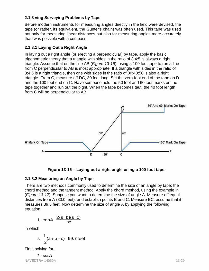
NAVEDTRA 14069A 13-29
2.1.8 ving Surveying Problems by Tape
Before modern instruments for measuring angles directly in the field were devised, the tape (or rather, its equivalent, the Gunter's chain) was often used. This tape was used not only for measuring linear distances but also for measuring angles more accurately than was possible with a compass.
2.1.8.1 Laying Out a Right Angle
In laying out a right angle (or erecting a perpendicular) by tape, apply the basic trigonometric theory that a triangle with sides in the ratio of 3:4:5 is always a right triangle. Assume that on the line AB (Figure 13-16); using a 100 foot tape to run a line from C perpendicular to AB is most appropriate. If a triangle with sides in the ratio of 3:4:5 is a right triangle, then one with sides in the ratio of 30:40:50 is also a right triangle. From C, measure off DC, 30 feet long. Set the zero-foot end of the tape on D and the 100 foot end on C. Have someone hold the 50 foot and 60 foot marks on the tape together and run out the bight. When the tape becomes taut, the 40 foot length from C will be perpendicular to AB.
Figure 13-16 – Laying out a right angle using a 100 foot tape.
2.1.8.2 Measuring an Angle by Tape
There are two methods commonly used to determine the size of an angle by tape: the chord method and the tangent method. Apply the chord method, using the example in (Figure 13-17). Suppose you want to determine the size of angle A. Measure off equal distances from A (80.0 feet), and establish points B and C. Measure BC; assume that it measures 39.5 feet. Now determine the size of angle A by applying the following equation:
1 cosA 2(s b)(s c)
bc
in which
s 1
(a b c) 99.7 feet 2
First, solving for:
1 - cosA
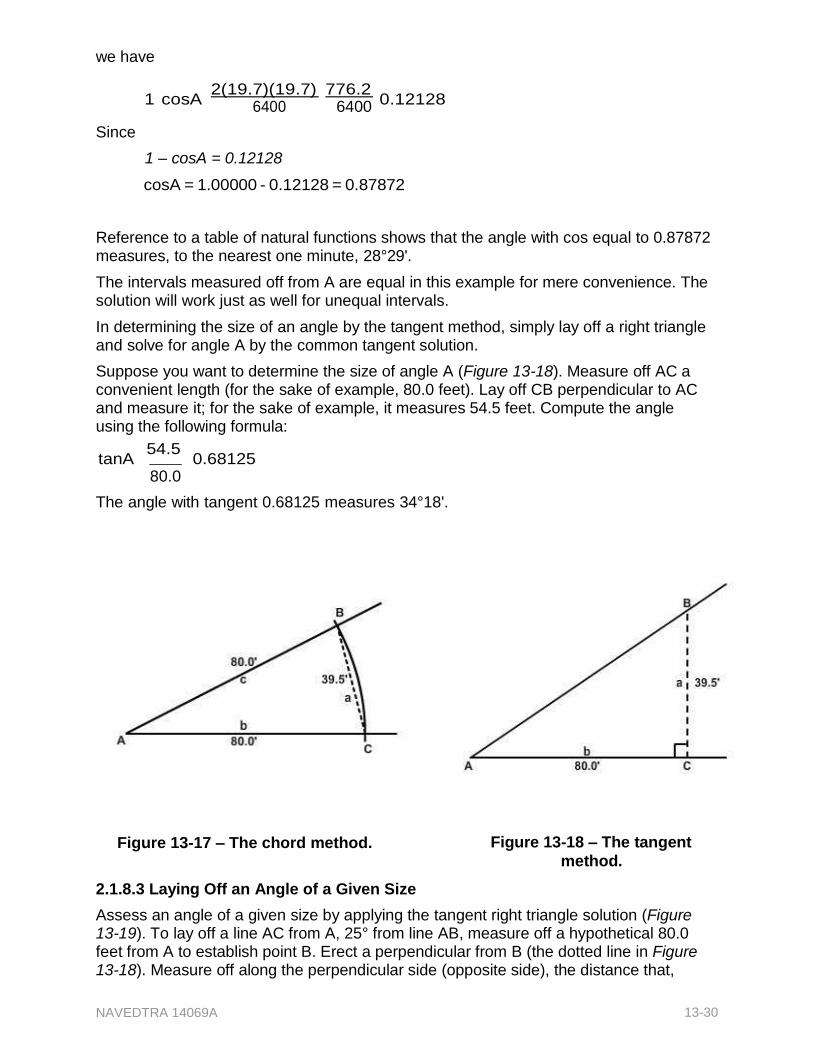
NAVEDTRA 14069A 13-30
we have
1 cosA 2(19.7)(19.7)
776.2
0.12128
Since
6400 1 – cosA = 0.12128
6400
cosA = 1.00000 - 0.12128 = 0.87872
Reference to a table of natural functions shows that the angle with cos equal to 0.87872 measures, to the nearest one minute, 28°29'.
The intervals measured off from A are equal in this example for mere convenience. The solution will work just as well for unequal intervals.
In determining the size of an angle by the tangent method, simply lay off a right triangle and solve for angle A by the common tangent solution.
Suppose you want to determine the size of angle A (Figure 13-18). Measure off AC a convenient length (for the sake of example, 80.0 feet). Lay off CB perpendicular to AC and measure it; for the sake of example, it measures 54.5 feet. Compute the angle using the following formula:
tanA 54.5
0.68125 80.0
The angle with tangent 0.68125 measures 34°18'.
Figure 13-17 – The chord method. Figure 13-18 – The tangent
method.
2.1.8.3 Laying Off an Angle of a Given Size
Assess an angle of a given size by applying the tangent right triangle solution (Figure 13-19). To lay off a line AC from A, 25° from line AB, measure off a hypothetical 80.0 feet from A to establish point B. Erect a perpendicular from B (the dotted line in Figure 13-18). Measure off along the perpendicular side (opposite side), the distance that,
NAVEDTRA 14069A 13-31
when divided by the adjacent side, will give the value of the natural tangent of 25°. Use the following formula:
tan25
a
80.0
a 80.0 tan25
The tangent of
25is 0.46631, so a = 80.0 x
0.46631 = 37.3 feet
Measure off 37.3 feet from B to establish point C. A line from A through C will form an angle of 25° from AB.
2.1.9 Identifying Chaining Mistakes and Errors
In surveying, there is a significant distinction between errors and mistakes. Errors result from factors such as the effects of nature,
Figure 13-19 – Laying off an angle of a given size.
the physical condition of the personnel performing the survey, and the condition of instruments. Mistakes, however, are simply human blunders. While errors may be compensated for, mistakes can be detected, corrected, and better yet, prevented only by the exercise of care.
2.1.9.1 Common Mistakes
Mistakes may result from poor work habits, lack of judgment, or confusion. They are often costly, time consuming, and difficult to detect. The easiest way to avoid them is to establish a finite procedure and follow it, being constantly alert during the operations in which mistakes are possible.
Some of the more common mistakes are as follows:
Failing to hold graduations plumb over points
Involuntarily transposing figures, such as recording 48.26 for 48.62
Misreading figures that are viewed upside down, such as recording an upside- down 9 as a 6
Reading a subdivided end-foot from the wrong end, as, for example, 0.28 feet instead of 0.22 feet
Associating subdivided end-foot reading with wrong whole-foot mark, as 38.21 feet instead of 37.21 feet
Subtracting incorrectly when using a minus tape
Omitting an entire tape length
2.1.9.2 Recognizing Common Errors
There are two types of errors: accidental and systematic. An accidental error is, generally speaking, one that may have a varying value.
Examples include:
Variation of the tension applied to the tape
NAVEDTRA 14069A 13-32
Inaccurate sticking of pins or other markings
Inaccurate determination of slope
You can minimize accidental errors simply by being careful, but they cannot be entirely eliminated. A systematic error has a constant value. The standard error in a tape, for example, is a systematic error. Temperature and sag corrections are applied to correct that particular systematic error. Systematic errors in general can be compensated for or otherwise eliminated by the application of corrections.
2.1.10 ring for and Maintaining a Survey Tape
If a steel or metallic tape gets a kink in it, it is consequently subjected to strain. The tape, in the best case scenario, will be distorted at the point where the kink lies. At worst, if the strain is strong enough, the tape will break at the point where the kink lies. Kinks, therefore, are to be avoided at all costs; it is especially important to avoid putting a strain on a tape that has a kink.
Under favorable circumstances, when a tape is shifted ahead, the head chainman may simply drag it over the ground. The rear chainman should not assist by dragging that end because this develops a curve in the tape. This curve may snag on an obstruction or cause a kink. When a tape is being dragged, the rear chainman should simply allow the end to trail along. The cardinal rule is "keep the tape straight."
When taping in traffic, plan your moves in advance and make the measurement as quickly as you can. If possible, do not let vehicles run over the tape; however, if this is absolutely unavoidable, be sure the tape is laid flat and taut on the road. Never let a vehicle run over a tape laid on a soft or rugged ground surface. Tapes are made as corrosion-resistant as possible, but no steel tape is entirely immune to corrosion, especially when used around salty water. Always wipe the tape dry before putting it away, and oil it periodically with light, rust-resistant oil. If a tape does rust, rubbing it with light steel wool dipped in a rust-removing compound is the best and safest way to remove the rust. Tapes, especially those in reels, should be removed from the reel and inspected each week for signs of corrosion. A damp climate in your area of operations could easily start corrosion of tapes.
2.1.11 Splicing a Tape
In spite of being carefully handled, tapes sometimes break. Rejoin a broken tape by splicing. Repair a relatively light tape with a punch-and-rivet tape splicer and repair stock (Figure 13-20). A repair stock consists of a length of tape of the same thickness and width as that of the broken tape. When reparining a tape, use a good section of the tape for calibration (matching a whole-foot mark). Place the section used for calibrating beside the broken section to maintain the original length of the tape after rejoining it.

NAVEDTRA 14069A 13-33
Figure 13-20 – A punch-and-rivet tape splicer with repair stock.
In splicing a broken tape, first align and rivet the repair stock at one end of the break. Next, place the repair stock on the face of the other section of the tape by using the calibrating section as a measure for the break splice. Insert one rivet at a time and arrange rivets in a triangular pattern. Do not place rivets closer together that one-fourth inch from center to center. Using a three-edge file, file partially through the surplus stock diagonally across the tape. The segment of the surplus will readily break off, leaving a clean splice. Repair heavy steel tapes in a similar manner, using a tape repair kit.
2.2.0 Measuring by the Electronic Distance-Measuring System
The electronic distance-measuring system is incorporated in various present-day surveying practices, including traverse and triangulation network. In traverse measurements, accurate distances are directly measured in a straight line and with minimum instrument setups. In triangulation, the system is used to conduct base line measurements precise enough to maintain survey accuracy.
In the electronic distance-measuring system, the length of a linear interval is determined by using equipment that sends out an electronic impulse of some sort, such as a radar microwave or a modulated light wave, and measures the time required for the impulse to travel the length of the interval. The velocity or rate of travel of the impulse is known. Therefore, once the time is also known, the length of the linear interval can be determined by applying the well-known equation "distance = rate x time."
Two types of Electronic Distance-Measuring devices (also called EDMs) commonly used today are microwave devices and light wave devices.
2.2.1 Measuring by Microwave Devices
The microwave distance-measuring device is an electronic instrument that transmits precisely controlled radio waves between two units. The waves are compared and electronically changed into a visually readable form from which the distance between the units can be computed.
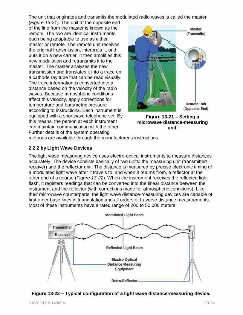
NAVEDTRA 14069A 13-34
The unit that originates and transmits the modulated radio waves is called the master (Figure 13-21). The unit at the opposite end of the line from the master is known as the remote. The two are identical instruments, each being adaptable to use as either master or remote. The remote unit receives the original transmission, interprets it, and puts it on a new carrier. It then amplifies this new modulation and retransmits it to the master. The master analyzes the new transmission and translates it into a trace on a cathode ray tube that can be read visually. The trace information is converted into a distance based on the velocity of the radio waves. Because atmospheric conditions affect this velocity, apply corrections for temperature and barometric pressure according to instructions. Each instrument is equipped with a shortwave telephone set. By this means, the person at each instrument can maintain communication with the other. Further details of the system operating
Figure 13-21 – Setting a microwave distance-measuring
unit.
methods are available through the manufacturer's instructions. 2.2.2 by Light Wave Devices
The light wave measuring device uses electro-optical instruments to measure distances accurately. The device consists basically of two units: the measuring unit (transmitter/ receiver) and the reflector unit. The distance is measured by precise electronic timing of a modulated light wave after it travels to, and when it returns from, a reflector at the other end of a course (Figure 13-22). When the instrument receives the reflected light flash, it registers readings that can be converted into the linear distance between the instrument and the reflector (with corrections made for atmospheric conditions). Like their microwave counterparts, the light wave distance-measuring devices are capable of first order base lines in triangulation and all orders of traverse distance measurements. Most of these instruments have a rated range of 200 to 50,000 meters.
Figure 13-22 – Typical configuration of a light wave distance-measuring device.
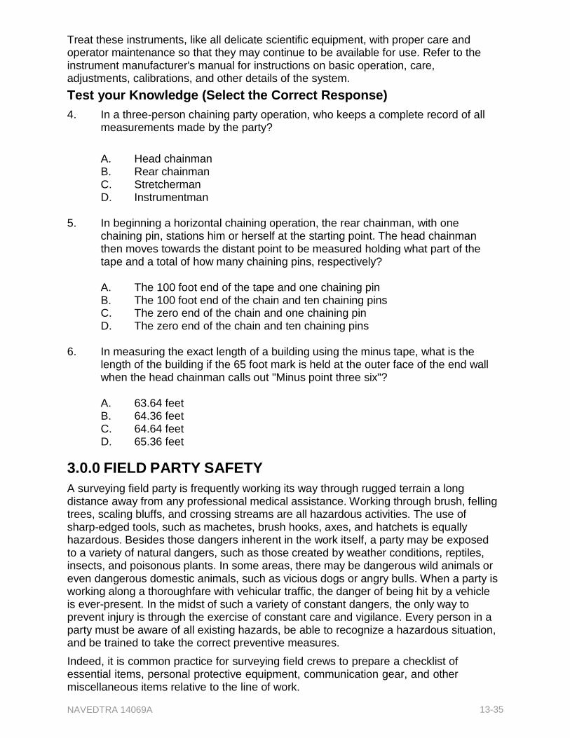
NAVEDTRA 14069A 13-35
Treat these instruments, like all delicate scientific equipment, with proper care and operator maintenance so that they may continue to be available for use. Refer to the instrument manufacturer's manual for instructions on basic operation, care, adjustments, calibrations, and other details of the system.
Test your Knowledge (Select the Correct Response)
4. In a three-person chaining party operation, who keeps a complete record of all measurements made by the party?
A. Head chainman B. Rear chainman C. Stretcherman D. Instrumentman
5. In beginning a horizontal chaining operation, the rear chainman, with one
chaining pin, stations him or herself at the starting point. The head chainman then moves towards the distant point to be measured holding what part of the tape and a total of how many chaining pins, respectively?
A. The 100 foot end of the tape and one chaining pin B. The 100 foot end of the chain and ten chaining pins C. The zero end of the chain and one chaining pin D. The zero end of the chain and ten chaining pins
6. In measuring the exact length of a building using the minus tape, what is the
length of the building if the 65 foot mark is held at the outer face of the end wall when the head chainman calls out "Minus point three six"?
A. 63.64 feet B. 64.36 feet C. 64.64 feet D. 65.36 feet
3.0.0 FIELD PARTY SAFETY
A surveying field party is frequently working its way through rugged terrain a long distance away from any professional medical assistance. Working through brush, felling trees, scaling bluffs, and crossing streams are all hazardous activities. The use of sharp-edged tools, such as machetes, brush hooks, axes, and hatchets is equally hazardous. Besides those dangers inherent in the work itself, a party may be exposed to a variety of natural dangers, such as those created by weather conditions, reptiles, insects, and poisonous plants. In some areas, there may be dangerous wild animals or even dangerous domestic animals, such as vicious dogs or angry bulls. When a party is working along a thoroughfare with vehicular traffic, the danger of being hit by a vehicle is ever-present. In the midst of such a variety of constant dangers, the only way to prevent injury is through the exercise of constant care and vigilance. Every person in a party must be aware of all existing hazards, be able to recognize a hazardous situation, and be trained to take the correct preventive measures.
Indeed, it is common practice for surveying field crews to prepare a checklist of essential items, personal protective equipment, communication gear, and other miscellaneous items relative to the line of work.
NAVEDTRA 14069A 13-36
3.1.0 Administering First Aid
If personal injuries do occur, they must be taken care of to the extent possible by the application of first aid. The Standard First Aid Training Course, NAVEDTRA 10081 (latest revision), defines first aid as "the emergency care given sick or injured persons until regular medical or surgical aid can be obtained." Your principal source of information on first aid is the Standard First Aid Training Course.
Every person in a field party, however junior in rate and experience, must be able to administer first aid. A chaining party may consist of only two persons, one of whom may be very junior in rate and time in service. If the party chief is the one injured, the junior member will be responsible for administering first aid.
As a rule, field crew members should be familiar with the telephone number and location of the hospital or dispensary nearest to where their party will be operating, have a transport vehicle available and ready, and have valid government vehicle operator's licenses. In addition, they should keep a first-aid kit handy at all times.
3.2.0 Protecting Against Weather Hazards
For all weather hazards, the best preventive measure is adequate protective clothing. When frostbite is a possibility, wear a hat that covers your ears, gloves/mittens for your hands, and cold weather footgear for your feet. These are the primary areas most subject to frostbite. Wear a hat when there is danger of heatstroke. Unless or until you are immune to sunburn (by tanning), keep your skin concealed from the sun. Fair haired or sandy-haired individuals, even when they tan, may be susceptible to a form of skin cancer caused by exposure to sunlight. If you are in this category, keep the skin covered whether you "tan" or not.
Two very common weather hazards, frostbite and heatstroke (commonly called sunstroke), are fully covered in the Standard First Aid Training Course. It does not mention lesser weather hazards, such as the exposure caused by wearing insufficient clothing in cold or wet weather and the possibility of a bad sunburn in hot weather. In general, when you set forth with a field party, wear or carry with you clothing that will provide adequate protection against the weather- not just the weather conditions at the time you set forth, but as they may develop before you get back.
3.3.0 Recognizing and Avoiding Poisonous Reptiles and Insects
The safest assumption regarding snakes or insects you do not recognize is that they are poisonous. The poisonous snakes of North America belong to the viper family. The distinguishing characteristics of a viper are a flat head and a thick body. The most common North American viper is the rattlesnake, distinguishable by a row of hard rings, called rattles, on the tail. The snake makes a rattling sound with them when it is angry or alarmed. The banded, or timber, rattler of the northeastern United States is smooth and silver-gray in color. The diamondback rattler of the United States deep south is silver-gray with a diamond-shaped pattern on the skin. The western diamondback rattler has the same diamond pattern, but is a copper color. The red rattler of southern California is a deeper copper color.
Besides the rattlesnake, the most common North American poisonous snake is the water moccasin, sometimes called the cottonmouth because of a white mouth lining that the snake exposes when preparing to strike. The skin of the water moccasin is dark brown with black bars on the upper side and black blotched with yellowish white on the

NAVEDTRA 14069A 13-37
under side. The reddish brown copperhead has no rattles. This viper is found especially in uplands of the eastern Unites States.
The most common poisonous insects encountered in North America are the black widow spider, the tarantula, and the scorpion. The black widow (which may be encountered anywhere in the United States) is recognizable by its small, shiny black body. The tarantula is a long-legged, hairy member of the spider family, found chiefly in and close to Texas. The scorpion, found mainly in the semi-tropical parts of the United States, resembles a lobster or crawfish in shape. The symptoms that develop from the bite of each of these reptiles and insects, together with the appropriate first aid, are thoroughly described in the Standard First Aid Training Course, NAVEDTRA 10081 (latest edition).
3.4.0 Avoiding or Treating Poisoning from Poisonous Plants
The Standard First Aid Training Course contains an extensive section on poisons. However, it does not mention a type of poisoning to which survey parties are particularly exposed- poisoning from contact with poisonous plants. Exposure to poisonous plants is not likely to be fatal (although it can be, under certain circumstances), but it can cause a lot of misery and considerable reduction in on-the-job efficiency. The most common poisonous plants in the United States are poison ivy, (including a variety called poison oak) and poison sumac, both of which occur everywhere in North America. These plants contain and exude a resinous juice that produces a severe reaction when it comes into contact with the skin of the average person. The first symptom of itching or a burning sensation may develop in a few hours or even after five days or more. The delay in the development of symptoms is often confusing when an attempt is made to determine the time or location where contact with the plant occurred. The itching sensation and subsequent inflammation, which usually develops into watery blisters under the skin, may continue for several days from a single contamination. Persistence of symptoms over a long period is most likely caused by new contacts with the plants or by contact with previously contaminated clothing or animals. Severe infection may produce more serious and painful symptoms such as abscesses, enlarged glands, fever, or other complications. Secondary infections are always possible in any break in the skin that occurs when the watery blisters break.
With poison ivy, the next development is usually the appearance of a scabrous, deep red rash over large skin areas. With poison sumac, large blisters filled with a thick yellowish white liquid strongly resembling pus usually occur. When the blisters break, this liquid runs over adjacent skin areas, enlarging the area of infection.
The resinous juice exuded by these poisonous plants is almost entirely non-volatile; that is, non-evaporating or will not dry up. Consequently, the juice may be carried on clothing, shoes, tools, or soil for long periods. In this way, it may infect persons who have not come into contact with the plants themselves. Individuals have, in fact, been severely infected by spores carried through air by smoke from burning plants. Infection by resinous juice carried on the fur of animals is another possible mode for exposure.
To avoid contact with the plants themselves, know what they look like. Poison ivy has a trefoil (three leaflets) leaf (Figure 13-23). The upper surface of the leaflet has a shiny, varnished appearance. The variety called poison oak has a serrated leaflet, or lobed, edges like that of an oak leaf (Figure 13-24). Ordinary poison ivy is usually a vine; and poison oak is usually a bush. In the flowering season, both types produce clusters of small white berries.

NAVEDTRA 14069A 13-38
Figure 13-23 – Different varieties of poison ivy leaves.
Some sumacs are poisonous, but others are harmless. It is difficult to distinguish the leaf of a poisonous sumac from the leaf of a nonpoisonous sumac. The only way to tell the poisonous plant from the harmless one is by the fruit. Both plants produce a drooping fruit cluster. The difference lies in the color of their fruits-that of the harmless sumac is red; that of the poison sumac is white. Outside of the fruit season, avoid contact with all sumacs. There are no "do-it-yourself" remedies for plant poisoning. Treatment for poisonous plant exposure must be administered or at least supervised by professional medical personnel. While treatment must be administered professionally, if you have reason to believe that you have been infected, wash thoroughly with water and an alkaline laundry soap. Do not use an oily soap (most facial soaps are oily) because they tend to spread the poison. Lather profusely, and do not rinse the lather off, but allow it to dry on the skin. Repeat this procedure every three to four hours, allowing the lather to dry each time. If job conditions make contact with plants unavoidable, wear gloves and long sleeve shirts and keep all other skin
Figure 13-24 – Poison oak.
areas covered. When you remove your clothing, take care not to allow any skin area to come into contact with exposed clothing, and launder all clothing at once.
3.5.0 Using Field Equipment Safely
The standard source of information on the safe use of dangerous field equipment and other safety precautions is Safety Precautions for Shore Activities, NAVMAT P-5100. A copy of this publication should be available in your technical library. Since tools are a
NAVEDTRA 14069A 13-39
potential source of danger in all occupations, inspect them periodically to assess whether they need any repairs and/or replacements. Only use tools that are in good condition. There should be no loose heads on any hand tools. Keep sharp-edged tools sharp. Store all tools safely when they are not in use. If you temporarily lay down tools with sharp blades or points, place them in such a way that no injury can result to anyone. Use sheaths or guards to carry sharp-edged or pointed tools from one place to another. If no sheath is available, carry a sharp-edged or pointed tool with the edge or point away from your body and take care not to injure others with it.
When working near other people, carry your range poles or level rods vertically against your body so that you will not injure another person's head or eyes if you turn suddenly. Do not hold a stake or bull-point with your hand around the shank while another person is driving it with a sledgehammer. Do not let a tape or plumb bob cord slide fast through your hands.
Always use tools correctly and for the task for which they are intended. For example, when cutting brush near the ground with a machete, swing away from your legs and feet. Never cut at short range from your body. Be sure that the radius of your swing is clear of obstructions, such as vines or twigs that might deflect the intended direction of the swing. Use your full arm's length to get a safe-swing radius. Always work at least 10 feet away from the nearest person. If it is necessary to use an ax to clear an area, prevent painful blisters by wearing a pair of thin gloves. Above all, use common sense and consider the possible results of your actions.
To climb poles and trees safely, use authorized climbing equipment. A lineman's pole climbers are made of steel and have a strap loop and short spur. Tree climbers have straps, pads for protection against friction, and a longer spur for penetrating bark. To avoid falling, use both the belt and the straps. Except in an emergency, never work in or on trees during a high wind. Watch out for power lines that may be in contact with the tree you are climbing.
Always conduct burning operations in the clear, where the fire will not ignite tree leaves or limbs, dry wooded areas, or nearby buildings. Remember that it is imperative to extinguish all burning or smoldering material completely before leaving it unattended. When practicable, use only nonflammable solvents for cleaning instruments. Do not leave the caps off or the stoppers out of flammable liquid containers. Use solvents only in well ventilated locations.
3.6.1 Following Safety Procedures in Traffic
A party working on a busy roadway is in constant danger of being struck. Every motion made by a member of such a party must be made with constant and complete awareness that vehicular traffic is proceeding as usual. Taking the following precautions, however, can minimize that danger:
Schedule work to take place during hours when traffic is slack (as much as possible). Work during "rush hour" on a metropolitan highway, for instance, could be so dangerous that it is an impractical endeavor.
Place adequate traffic warning signs, such as "Men Working," "Drive Slowly," "Single Lane Ahead," and the like, where they will be most effective in warning drivers and, if possible, in detouring traffic away from the field party.
Post a flagman at each end of the work area if detouring requires two-way traffic on a single lane.
NAVEDTRA 14069A 13-40
Make signs, barriers, and equipment in use, such as instruments, targets, and the like, as conspicuous as possible by the attachment of bright-colored bunting. Personnel should also make themselves as conspicuous as possible by wearing orange-colored shirts, vests, or jackets.
Put personal safety above all else.
Test Your Knowledge (Select the Correct Response)
7. Which of the following descriptions is characteristic of poisonous snakes found on the North American continent?
A. Brightly colored B. Smaller than nonpoisonous snakes C. Flat headed and thick bodied D. Equipped with tail rattles
8. What North American poisonous snake shows the white lining inside its mouth
just before striking?
A. Copperhead B. Rattler C. Coral D. Water moccasin
9. A poisonous plant has a juice that is nonvolatile. This means that the juice of this
plant will:
A. Evaporate quickly B. Not stain clothing C. Not evaporate quickly D. Not infect a person unless the plant itself is touched
4.1.1 ADDITIONAL DUTIES of a SURVEY CREW
A survey crew member may perform other tasks, including:
Maintenance of surveying equipment and accessories
Preparation of the field party's essential needs
Field sanitation
Conducting prestart checks and operator's maintenance of government survey vehicles.
4.1.0 Maintaining Surveying Equipment
Generally, the maintenance of surveying equipment and accessories involves proper cleaning and stowage. For example, steel tapes, brush hooks, axes, chain saws, and so forth, must be cleaned and dried and, if necessary, a thin coat of oil applied after each day's work before equipment is stored for the night. Never stow any surveying gear (especially if made of ferrous material) without checking it thoroughly to ensure it is clean and dry- this is particularly important for steel tapes.
NAVEDTRA 14069A 13-41
SEABEEs have a multitude of jobs done under variable conditions, sometimes using the same equipment, sometimes using different equipment. Because of this, neglecting the proper care of equipment for even one day can result in rusty, inoperable equipment, and financial responsibility for government property loss or damage due to negligence falls on you.
Regularly sharpen surveying clearing tools, and replace any broken handles (especially those on sledgehammers). For delicate equipment, consult the manufacturer's handbook or other applicable publications before attempting any servicing or cleaning. When necessary, ask your senior EA to explain the correct procedure.
4.2.0 Preparing for Field Party’s Essential Needs
Party chiefs prepare lists of equipment and supplies needed for each day, and it is the responsibility of everyone in the survey party to review the list and ensure that everything needed is in fact present on the list. When reviewing the field party's essential needs list, remember to consider your personal needs in addition to the equipment necessary for the job, especially if the job is a significant distance from base camp.
In a triangulation survey, for example, your stations are generally situated in remote places. You may be ferried to your station point by helicopter or by some other means, depending on the location and the mode of transportation available. Be sure to take extra drinking water to jobs like this, and do not discard your excess water until you are safely back to base camp.
4.3.0 Maintaining Field Sanitation
In the field, devices necessary for maintaining personal hygiene and field sanitation are improvised. If you are surveying at a remote location, you are unlikely to find a waterborne sewage system available for your use. The typical alternative is digging a "cat hole" about one foot deep and burying all waste completely.
Always dispose of garbage properly during field surveys. Whenever possible, avoid burning dry garbage on site. Disposal bags offer a good means of preventing litter; use them whenever available. In extremely hot climates, your supply of potable water will run low at a faster rate. To avoid dehydration, you must treat your own water or face infections or diseases such as dysentery, cholera, diarrhea, and typhoid fever. It is imperative that water taken from any source (such as lakes, rivers, streams, and ponds) be properly treated before being used, as all these sources are presumed to be contaminated. To treat water for drinking, use either a plastic or aluminum canteen with the water purification compounds available in tablet form (iodine) or in ampule form (calcium hypochlorite). When disinfecting compounds are not available, boiling the water is another method for killing disease-producing organisms. The standard source of information for SEABEEs on field sanitation and personal hygiene is Seabee Combat Handbook, NAVEDTRA 10479-C2, chapter 8.
4.4.0 Giving Vehicle Prestart Checks and Maintaining Vehicle Operations
The field survey crew is likely to be assigned a vehicle to transport people and equipment to and from the jobsite. Before operating the vehicle, the operator will give it a prestart check to make sure that it is ready to run. When a vehicle is assigned to you, an operator's daily pre-service maintenance report is issued at the dispatch office. Use this form to record or log items in the vehicle that require attention as observed during
NAVEDTRA 14069A 13-42
the prestart check and during the working day. Other information, such as mileage readings, operating hours, and fuel consumption may also be required. A complete checklist of the vehicle prestart and operator's maintenance procedures are described in Equipment Operator 3 & 2, NAVEDTRA 10640-J1, chapters 2 and 4.
Test Your Knowledge (Select the Correct Response)
10. (True or False) In addition to surveying duties, a survey crew member may be responsible for picking up trash.
A. True B. False
11. All lake, river, stream, and pond water is presumed what?
A. Fresh B. Potable C. Contaminated
12. (True or False) Boiling is a sufficient method for killing disease-producing
organisms in water.
A. True B. False
Summary
In this chapter, you were presented with information relating to direct linear measurements and field survey safety. You were introduced to the specific duties of a chaining crew member including marking control reference and monument points, making direct linear measurements, correcting measurements and preparing chain notes. This topic addressed solving surveying problems with the tape, identifying chaining mistakes and errors, caring for and maintaining survey tape, and splicing tape.
You also learned about measuring with the Electronic Distance-Measuring System, with both a microwave device and a light wave device.
You were presented with information relating to field party safety, which emphasized first aid administration, protection from weather, avoidance and treatment of poisons in nature, safe use of equipment, and caution in high traffic situations.
The end of this chapter was devoted to the additional duties of the survey crew in which you learned about survey equipment maintenance, preparation for essential needs, field sanitation maintenance, and prestart vehicle checks.

NAVEDTRA 14069A 13-43
Review Questions (Select the Correct Response) 1. The instrumentman is moving his right arm, which is extended upward, and to the
right. What message is he signaling to the rodman?
A. The rodman must move the rod to the right. B. The rodman must move the top of the rod to the right until it is vertical. C. The rodman must move the rod to the left. D. The rodman must move the top of the rod to the left until it is vertical.
2. An instrumentman extends both arms upward. What does this indicate to the
rodman?
A. Move forward. B. Reverse the rod. C. Pick up the instrument. D. Face the rod.
3. The instrumentman extends both arms out horizontally from his shoulders and
waves them up and down. What message is he giving to the rodman?
A. Come in B. Pick up the instrument C. All right D. Move forward
4. In clearing the chaining line, what should you do when a valuable tree lies
directly in your path?
A. Triangulate around it B. Request that the owner cut down the tree, or that he allow you to cut down
the tree C. Cut it down D. Choose a different chaining line
5. For what reason should a chainman use an indicator that is narrower than a
range pole when holding on or plumbing over a point for short sights?
A. To enable the instrumentman to align the indicator exactly with the vertical cross hair of the instrument
B. To enable the instrument to sight beyond the point C. To enable the chainman to carry out duties without becoming fatigued D. To enable the chain man to hold the indicator steady
NAVEDTRA 14069A 13-44
6. When running a line from point A to point B, what action does the instrumentman take when he or she "plunges" the telescope?
A. Turns the telescope 180 degrees to the right from a sight on point A to a
sight on point B B. Rotates the telescope vertically from a sight on point A to a sight on point
B C. Turns the telescope 180 degrees to the left from a sight on point A to a
sight on point B D. Moves the telescope from point A to point B
7. When plumbing over a point, which of the following actions should you take to
overcome the problem of wind blowing the plumb bob back and forth?
A. Rest the point of the plumb bob on the point being plumbed. B. Bounce the point of the plumb bob slightly up and down on the point being
plumbed. C. Shorted the plumb bob cord. D. Have a second person hold the point of the plumb bob steady on the point
being plumbed. 8. You should mark the horizontal location of a point over which to plumb a transit
by which of the following means?
A. A flag or chaining pin B. A leveling rod or range pole C. A precise marker driven or set in the top of the hub D. A bull-point or spad
9. Survey control points are marked in the field by which of the following means?
A. Bronze disks set in concrete B. Center-punched metal rods driven flush with the ground C. Wooden stakes or soda pop tops and nails driven flush with the ground D. Each of the above
10. In addition to an identifying symbol, what marking is usually placed on a bench
mark constructed by surveyors to identify a point for a construction project?
A. The abbreviation for bench mark, BM B. The elevation of the bench mark C. A number showing the order in which the bench mark is to be considered D. A number denoting the distance of the bench mark from the point of
beginning
NAVEDTRA 14069A 13-45
11. As survey control points are established in the field, in what manner are they recorded in the field notebook?
A. By sketch B. By word description C. By either A or B, or a combination of both D. By detailed drawing
12. What tool is used to mark a terminal point in a chaining operation when the
distance being measured is greater than the tape length?
A. Surveyor's arrow B. Chaining pin C. Philadelphia rod D. Range pole
13. When the head chainman runs out of chaining pins, what total number of pins
should the rear chainman have?
A. 0
B. 1
C. 9
D. 10
14. Which of the following devices helps apply the correct tension to a tap that is supported at its ends only?
A. Taping stool B. Spring balance C. Scissors clamp D. Chaining buck
15. Including the 0 foot mark, a total of how many whole foot marks are indicated on
a 100 foot plus tape?
A. 99
B. 100
C. 101
D. 102
16. When slope chaining, which of the following can you obtain by direct reading?
A. Slope angle only B. Slope angle and slope distance C. Horizontal distance only D. Slope angle and horizontal distance
NAVEDTRA 14069A 13-46
17. In horizontal chaining operations, a call of a "mark" from the rear chainman signals the head chainman to take which of the following actions?
A. Pull the end of the tape B. Stick a chaining pin into the ground C. Measure the tension on the tape D. Release the plumb bob
18. When team members are making a horizontal measurement on a slope, the
chainman on the lower level determines at what height the chainman on the higher level will hold the tape by using what instrument?
A. A transit B. A theodolite C. A hand level D. A plumb bob
19. In which of the following situations should the breaking tape method of
measuring be used?
A. Determining the horizontal distance between points on terrain having a six to one slope ratio
B. Measuring the width of major access roads C. Measuring horizontal distances in heavily wooded and obstructed areas D. All of the above
20. A two-person party is using the breaking chain procedure and a 100 foot tape to
chain a line on a steep slope. When, if ever, does the rear chainman give the front chainman a chaining pin?
A. Each time only a 25 foot distance is measured B. Each time only a 50 foot distance is measured C. Each time an even foot distance of less than 100 feet is measured D. Never
21. The standard error of a 100 foot tape can be determined in which of the following
ways?
A. By calibration by the Bureau of Standards B. By comparison with a length of a calibrated 100 foot tape C. By comparison with a known 100 foot distance D. By each of the above means
22. When calibrating a tape, remember that the standard tension and corresponding
temperature for a 100 foot tape supported throughout is what?
A. 5 pounds at 65 degrees B. 10 pounds at 68 degrees C. 15 pounds at 68 degrees D. 20 pounds at 65 degrees
NAVEDTRA 14069A 13-47
23. A 100 foot tape has a standard error of 0.003 feet. What is the total error for a taped distance of 471.56 feet (rounding off to the nearest 0.01 foot)?
A. 0.00
B. 0.01
C. 0.02
D. 0.05
24. Under standard conditions, a tape indicates 100.00 feet when it should actually measure 99.996 feet. Using this tape, how far should you measure to see a point 450 feet away from another point?
A. 449.96
B. 449.98
C. 450.02
D. 450.04
25. A tape has a standard error which causes it to indicate 99.996 feet when it actually measures 100.00 feet. What is the actual distance between two points if the taped distance is 259.05 feet?
A. 259.04
B. 259.05
C. 259.06
D. 260.00
26. A steel tape is used to lay out the distance from point A to point B. If the thermometer attached to the tape reads 79 degrees, what is the actual distance laid to offset the effect of change in temperature?
A. 168.09
B. 168.99
C. 169.01
D. 169.07
27. A steel tape is used to lay out the distance from point A to point B. If the thermometer attached to the tape reads 35 degrees, how much should be added or subtracted to the measurement in order to compensate for the change in temperature?
A. Add 0.02 feet B. Subtract 0.02 feet C. Add 0.04 feet D. Subtract 0.04 feet
28. A three pound, 100 foot tape is used to measure 60 feet. If the chainman
maintained a pull of 20 pounds what is the correction of sag?
A. 0.02 feet B. 0.03 feet C. 0.04 feet D. 0.05 feet
NAVEDTRA 14069A 13-48
2
29. When is the slope correction subtracted from the taped slope distance?
A. When taping uphill only B. When taping downhill only C. When applying the slope correction formula for 10 percent slopes only D. Always
30. When determining accurate slope correction, what is the maximum slope for
which you should use the following formula?
C h
h
2s
A. 5%
B. 10%
C. 20%
D. 30%
31. What is the proper way to correct an error in field notes?
A. Erase the error B. Blot out the error C. Draw a line through the error and enter the correct information above D. Circle and initial the error
32. In which of the following ratios does the length of the sides indicate that the
triangle is a right triangle?
A. 10:15:20 B. 18:24:30 C. 20:30:40 D. 30:40:50
33. Computing the size of an angle by the chord method involves the partial solution
of a triangle in which the only known values are which of the following measurements?
A. The size of two angles B. The length of the sides C. The seize of two angles and length of one side D. The lengths of two sides and the size of one angle
34. Reading a tape upside down and obtaining, for example, 69 instead of 96 and
leaving out an entire tape length are samples of what?
A. Natural errors B. Instrumental errors C. Personal errors D. Mistakes
NAVEDTRA 14069A 13-49
35. In caring for and maintaining steel tapes, a chainman should make it a practice to take which of the following steps?
A. Inspect all tapes weekly B. Wipe them dry before storing them C. Coat them from time to time with light rust-resistant oil D. All of the above
36. What is the proper sequence of steps in splicing a broken steel tape?
1. Align and rivet the repair stock at one end of the break. 2. Insert one rivet at a time and arrange the rivets in a triangular pattern 3. Place the repair stock on the face of the other section of the tape, using
the calibration section as a measure for the break splice. 4. Use a three-edge file to partially cut through the surplus stock
A. 1, 2, 3, 4 B. 1, 3, 2, 4 C. 3, 1, 2, 4 D. 4, 2, 1, 3
37. In which of the following ways are microwave and light wave EDM devices the
same?
A. Both have interchangeable transmitters and receivers B. Both require the application of correction for atmospheric conditions C. Both are used for the direct measurement of distances D. Both should be used for only short distances of less than 600 feet
38. What symptom is usually the first to be noticed by someone who has come in
contact with poison ivy or poison oak?
A. A cluster of large blisters B. A deep red rash C. An extreme itching D. A cluster of small blisters
39. Poisonous sumac can be distinguished from nonpoisonous sumac in what way?
A. It bears red berries B. It has more leaves C. It bears white fruit D. It grows closer to the ground
40. The first-aid procedure for plant poisoning of the skin consists of which of the
following steps?
A. Soaping and rinsing frequently B. Applying a light coat of oil C. Obtaining immediate medical care D. Soaping with an alkaline laundry soap and not rinsing it off

NAVEDTRA 14069A 13-50
41. While surveying, the members of a field party must work on and near a heavily traveled highway that they are forced to cross several times a day. They can reduce the danger of being struck by a moving vehicle by taking which of the following precautions?
A. Wearing brightly colored outer clothing B. Detouring traffic away from the field party C. Erecting conspicuous signs and barriers D. All of the above

NAVEDTRA 14069A 13-51
Trade Terms Introduced in this Chapter
Blaze A mark made upon a tree trunk usually at about breast height.
Catenary The curve assumed approximately by a heavy uniform cord or chain hanging freely from two points not in the same vertical line.
HI The height of instrumentation.
Kickout A cleared space for dropping the plumb bob.
Breaking tape The procedure for measuring directly horizontal distance on sloping ground, or through obstacles that do not permit the use of a full tape length.
EDMs Electronic Distance Measurements

NAVEDTRA 14069A 13-52
Additional Resources and References
This chapter is intended to present thorough resources for task training. The following reference works are suggested for further study. This is optional material for continued education rather than for task training.
Seabee Combat Handbook, NAVEDTRA 14234, Naval Education and Training Program Management Support Activity, Pensacola, Fla., 2003.
Standard First Aid Training Course, NAVEDTRA 10081-D, Naval Education and Training Program Development Center, Pensacola, Fla., 1982.
U.S. Department of Defense, Elements of Surveying, TM 5-232, Headquarters, Department of the Army, Washington, D.C., 1971.

NAVEDTRA 14069A 13-53
CSFE Nonresident Training Course – User Update
CSFE makes every effort to keep their manuals up-to-date and free of technical errors. We appreciate your help in this process. If you have an idea for improving this manual, or if you find an error, a typographical mistake, or an inaccuracy in CSFE manuals, please write or email us, using this form or a photocopy. Be sure to include the exact chapter number, topic, detailed description, and correction, if applicable. Your input will be brought to the attention of the Technical Review Committee. Thank you for your assistance.
Write: CSFE N7A 3502 Goodspeed St. Port Hueneme, CA 93130
FAX: 805/982-5508
E- mail: CSFE [email protected]
Rate Course Name
Revision Date Chapter Number Page Number(s)
Description
(Optional) Correction
(Optional) Your Name and Address
NAVEDTRA 14069A 14-1
Chapter 14
Horizontal Control
Topics
1.0.0 Directions and Distances
2.0.0 Transit-Tape Survey
3.0.0 Organizing the Party
To hear audio, click on the box.
Overview
Locating points, objects, and/or details on the surface of the earth requires an established system of control stations. An EA can easily determine the relative positions of detail points if these points are tied into a local control station, or if the control station is tied into a geodetic control, those positions can be located relative to a worldwide control system.
The main control system is formed by a triangulation network supplemented by a line surveyed across a plot of ground (a traverse). A traverse that has been established and is used to locate detail points and objects is often called a control traverse. Any line from which points and objects are located is a control line. A survey is controlled horizontally by measuring horizontal distances and horizontal angles. This type of survey is often referred to as a horizontal control.
Additionally, horizontal control surveys establish supplementary control stations for use in construction surveys. Supplementary control stations usually consist of one or more short traverses running close to or across a construction area to afford easy tie-ins for various projects. These stations are established to the degree of accuracy needed for the purpose of the survey.
In this chapter, we will identify common procedures used in converting angular measurements taken from a compass or transit survey, recognize the methods used in establishing horizontal control, and identify various field procedures used in running a traverse survey.
Objectives
When you have completed this chapter, you will be able to do the following:
1. Describe the procedures for determining distance and direction.
2. Describe the procedures for conducting transit tape surveys.
3. Describe the procedures for conducting traverse operations.
NAVEDTRA 14069A 14-2
Prerequisites
None
This course map shows all of the chapters in Engineering Aid Basic. The suggested training order begins at the bottom and proceeds up. Skill levels increase as you advance on the course map.
Topographic Surveying and Mapping
E
Indirect Leveling/Level and Traverse Computations N
G Care and Adjustment of Survey Equipment
I
Materials Testing: Soil and Concrete N
Direct Leveling and Basic Engineering Surveys E
Horizontal Control E
Direct Linear Measurements and Field Survey Safety R
I Surveying: Elements and Equipment
N Construction Drawings
G
Electrical: Systems and Plans
Mechanical: Systems and Plans AID
Concrete and Masonry
B
Wood and Light Frame Structures A
Drafting: Projections and Sketching S
Drafting: Geometric Construction I
Drafting: Fundamentals and techniques C
Drafting: Equipment
Mathematics and Units of Measurement
Engineering Aid Rating

NAVEDTRA 14069A 14-3
Features of this Manual
This manual has several features which make it easy to use online.
Figure and table numbers in the text are italicized. The figure or table is either next to or below the text that refers to it.
The first time a glossary term appears in the text, it is bold and italicized. When your cursor crosses over that word or phrase, a popup box displays with the appropriate definition.
Audio and video clips are included in the text, with an italicized instruction telling you where to click to activate it.
Review questions that apply to a section are listed under the Test Your Knowledge banner at the end of the section. Select the answer you choose. If the answer is correct, you will be taken to the next section heading. If the answer is incorrect, you will be taken to the area in the chapter where the information is for review. When you have completed your review, select anywhere in that area to return to the review question. Try to answer the question again.
Review questions are included at the end of this chapter. Select the answer you choose. If the answer is correct, you will be taken to the next question. If the answer is incorrect, you will be taken to the area in the chapter where the information is for review. When you have completed your review, select anywhere in that area to return to the review question. Try to answer the question again.
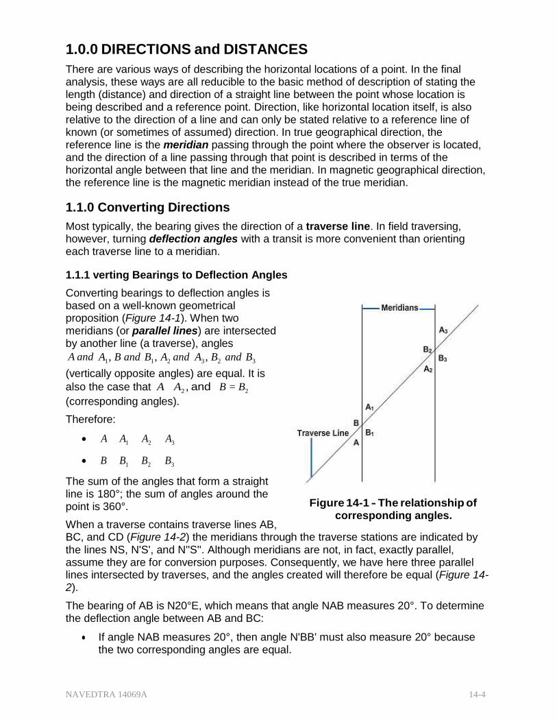
NAVEDTRA 14069A 14-4
1.0.0 DIRECTIONS and DISTANCES
There are various ways of describing the horizontal locations of a point. In the final analysis, these ways are all reducible to the basic method of description of stating the length (distance) and direction of a straight line between the point whose location is being described and a reference point. Direction, like horizontal location itself, is also relative to the direction of a line and can only be stated relative to a reference line of known (or sometimes of assumed) direction. In true geographical direction, the reference line is the meridian passing through the point where the observer is located, and the direction of a line passing through that point is described in terms of the horizontal angle between that line and the meridian. In magnetic geographical direction, the reference line is the magnetic meridian instead of the true meridian.
1.1.0 Converting Directions
Most typically, the bearing gives the direction of a traverse line. In field traversing, however, turning deflection angles with a transit is more convenient than orienting each traverse line to a meridian.
1.1.1 verting Bearings to Deflection Angles
Converting bearings to deflection angles is based on a well-known geometrical proposition (Figure 14-1). When two meridians (or parallel lines) are intersected by another line (a traverse), angles
A and A1 , B and B1 , A2 and A3 , B2 and B3
(vertically opposite angles) are equal. It is
also the case that A A2 , and B = B2
(corresponding angles).
Therefore:
A A1 A2 A3
B B1 B2 B3
The sum of the angles that form a straight line is 180°; the sum of angles around the point is 360°.
When a traverse contains traverse lines AB,
Figure 14-1 - The relationship of corresponding angles.
BC, and CD (Figure 14-2) the meridians through the traverse stations are indicated by the lines NS, N'S', and N''S''. Although meridians are not, in fact, exactly parallel, assume they are for conversion purposes. Consequently, we have here three parallel lines intersected by traverses, and the angles created will therefore be equal (Figure 14- 2).
The bearing of AB is N20°E, which means that angle NAB measures 20°. To determine the deflection angle between AB and BC:
If angle NAB measures 20°, then angle N'BB' must also measure 20° because the two corresponding angles are equal.
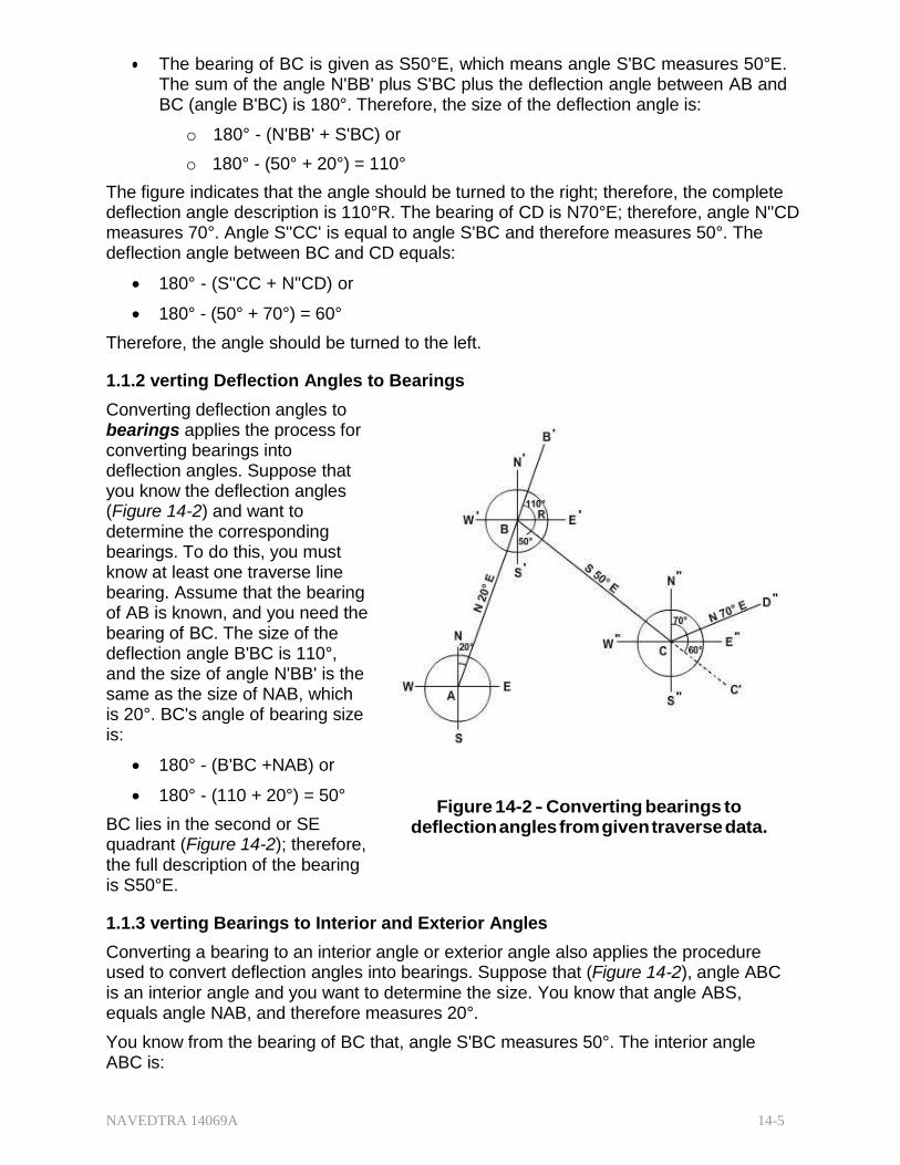
NAVEDTRA 14069A 14-5
The bearing of BC is given as S50°E, which means angle S'BC measures 50°E. The sum of the angle N'BB' plus S'BC plus the deflection angle between AB and BC (angle B'BC) is 180°. Therefore, the size of the deflection angle is:
o 180° - (N'BB' + S'BC) or
o 180° - (50° + 20°) = 110°
The figure indicates that the angle should be turned to the right; therefore, the complete deflection angle description is 110°R. The bearing of CD is N70°E; therefore, angle N''CD measures 70°. Angle S''CC' is equal to angle S'BC and therefore measures 50°. The deflection angle between BC and CD equals:
180° - (S''CC + N''CD) or
180° - (50° + 70°) = 60°
Therefore, the angle should be turned to the left. 1.1.2 verting Deflection Angles to Bearings
Converting deflection angles to bearings applies the process for converting bearings into deflection angles. Suppose that you know the deflection angles (Figure 14-2) and want to determine the corresponding bearings. To do this, you must know at least one traverse line bearing. Assume that the bearing of AB is known, and you need the bearing of BC. The size of the deflection angle B'BC is 110°, and the size of angle N'BB' is the same as the size of NAB, which is 20°. BC's angle of bearing size is:
180° - (B'BC +NAB) or
180° - (110 + 20°) = 50°
BC lies in the second or SE quadrant (Figure 14-2); therefore, the full description of the bearing is S50°E.
Figure 14-2 - Converting bearings to deflection angles from given traverse data.
1.1.3 verting Bearings to Interior and Exterior Angles
Converting a bearing to an interior angle or exterior angle also applies the procedure used to convert deflection angles into bearings. Suppose that (Figure 14-2), angle ABC is an interior angle and you want to determine the size. You know that angle ABS, equals angle NAB, and therefore measures 20°.
You know from the bearing of BC that, angle S'BC measures 50°. The interior angle ABC is:
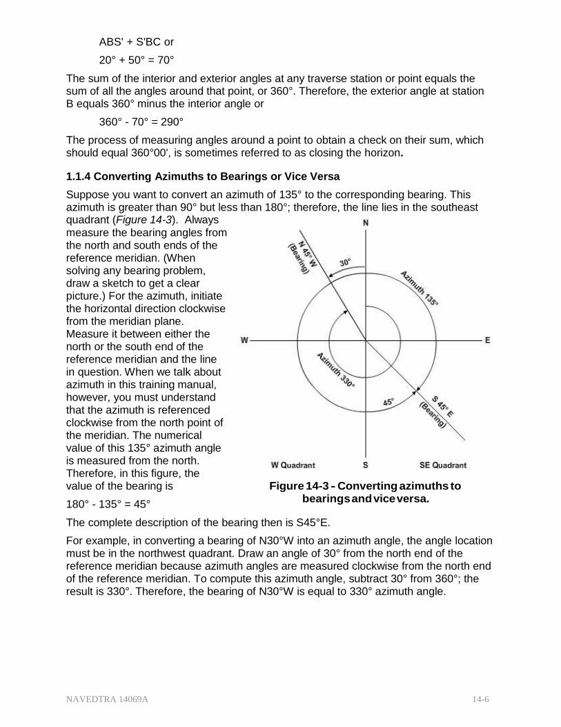
NAVEDTRA 14069A 14-6
ABS' + S'BC or
20° + 50° = 70°
The sum of the interior and exterior angles at any traverse station or point equals the sum of all the angles around that point, or 360°. Therefore, the exterior angle at station B equals 360° minus the interior angle or
360° - 70° = 290°
The process of measuring angles around a point to obtain a check on their sum, which should equal 360°00', is sometimes referred to as closing the horizon.
1.1.4 Converting Azimuths to Bearings or Vice Versa
Suppose you want to convert an azimuth of 135° to the corresponding bearing. This azimuth is greater than 90° but less than 180°; therefore, the line lies in the southeast quadrant (Figure 14-3). Always measure the bearing angles from the north and south ends of the reference meridian. (When solving any bearing problem, draw a sketch to get a clear picture.) For the azimuth, initiate the horizontal direction clockwise from the meridian plane. Measure it between either the north or the south end of the reference meridian and the line in question. When we talk about azimuth in this training manual, however, you must understand that the azimuth is referenced clockwise from the north point of the meridian. The numerical value of this 135° azimuth angle is measured from the north. Therefore, in this figure, the value of the bearing is
180° - 135° = 45°
Figure 14-3 - Converting azimuths to bearings and vice versa.
The complete description of the bearing then is S45°E.
For example, in converting a bearing of N30°W into an azimuth angle, the angle location must be in the northwest quadrant. Draw an angle of 30° from the north end of the reference meridian because azimuth angles are measured clockwise from the north end of the reference meridian. To compute this azimuth angle, subtract 30° from 360°; the result is 330°. Therefore, the bearing of N30°W is equal to 330° azimuth angle.
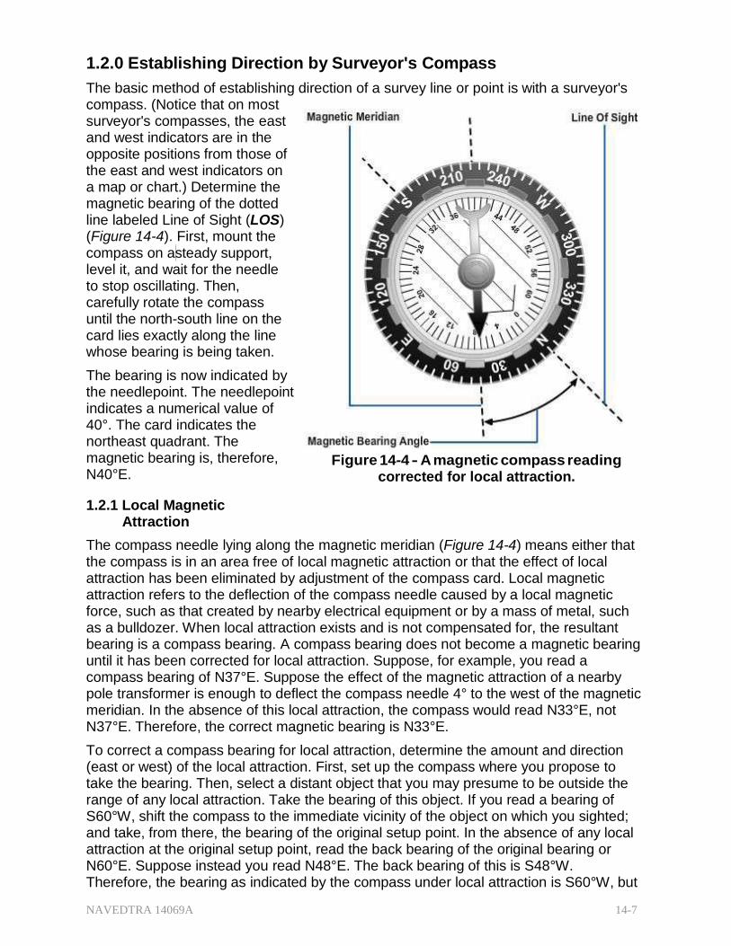
NAVEDTRA 14069A 14-7
1.2.0 Establishing Direction by Surveyor's Compass
The basic method of establishing direction of a survey line or point is with a surveyor's compass. (Notice that on most surveyor's compasses, the east and west indicators are in the opposite positions from those of the east and west indicators on a map or chart.) Determine the magnetic bearing of the dotted line labeled Line of Sight (LOS) (Figure 14-4). First, mount the compass on asteady support, level it, and wait for the needle to stop oscillating. Then, carefully rotate the compass until the north-south line on the card lies exactly along the line whose bearing is being taken.
The bearing is now indicated by the needlepoint. The needlepoint indicates a numerical value of 40°. The card indicates the northeast quadrant. The magnetic bearing is, therefore, N40°E.
1.2.1 Local Magnetic
Attraction
Figure 14-4 - A magnetic compass reading corrected for local attraction.
The compass needle lying along the magnetic meridian (Figure 14-4) means either that the compass is in an area free of local magnetic attraction or that the effect of local attraction has been eliminated by adjustment of the compass card. Local magnetic attraction refers to the deflection of the compass needle caused by a local magnetic force, such as that created by nearby electrical equipment or by a mass of metal, such as a bulldozer. When local attraction exists and is not compensated for, the resultant bearing is a compass bearing. A compass bearing does not become a magnetic bearing until it has been corrected for local attraction. Suppose, for example, you read a compass bearing of N37°E. Suppose the effect of the magnetic attraction of a nearby pole transformer is enough to deflect the compass needle 4° to the west of the magnetic meridian. In the absence of this local attraction, the compass would read N33°E, not N37°E. Therefore, the correct magnetic bearing is N33°E.
To correct a compass bearing for local attraction, determine the amount and direction (east or west) of the local attraction. First, set up the compass where you propose to take the bearing. Then, select a distant object that you may presume to be outside the range of any local attraction. Take the bearing of this object. If you read a bearing of S60°W, shift the compass to the immediate vicinity of the object on which you sighted; and take, from there, the bearing of the original setup point. In the absence of any local attraction at the original setup point, read the back bearing of the original bearing or N60°E. Suppose instead you read N48°E. The back bearing of this is S48°W. Therefore, the bearing as indicated by the compass under local attraction is S60°W, but
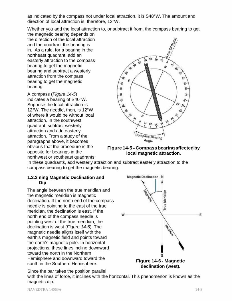
NAVEDTRA 14069A 14-8
as indicated by the compass not under local attraction, it is S48°W. The amount and direction of local attraction is, therefore, 12°W.
Whether you add the local attraction to, or subtract it from, the compass bearing to get the magnetic bearing depends on the direction of the local attraction and the quadrant the bearing is in. As a rule, for a bearing in the northeast quadrant, add an easterly attraction to the compass bearing to get the magnetic bearing and subtract a westerly attraction from the compass bearing to get the magnetic bearing.
A compass (Figure 14-5) indicates a bearing of S40°W. Suppose the local attraction is 12°W. The needle, then, is 12°W of where it would be without local attraction. In the southwest quadrant, subtract westerly attraction and add easterly attraction. From a study of the paragraphs above, it becomes obvious that the procedure is the opposite for bearings in the northwest or southeast quadrants.
Figure 14-5 - Compass bearing affected by local magnetic attraction.
In these quadrants, add westerly attraction and subtract easterly attraction to the compass bearing to get the magnetic bearing.
1.2.2 ning Magnetic Declination and Dip
The angle between the true meridian and the magnetic meridian is magnetic declination. If the north end of the compass needle is pointing to the east of the true meridian, the declination is east. If the north end of the compass needle is pointing west of the true meridian, the declination is west (Figure 14-6). The magnetic needle aligns itself with the earth's magnetic field and points toward the earth's magnetic pole. In horizontal projections, these lines incline downward toward the north in the Northern Hemisphere and downward toward the south in the Southern Hemisphere.
Since the bar takes the position parallel
Figure 14-6 - Magnetic declination (west).
with the lines of force, it inclines with the horizontal. This phenomenon is known as the magnetic dip.
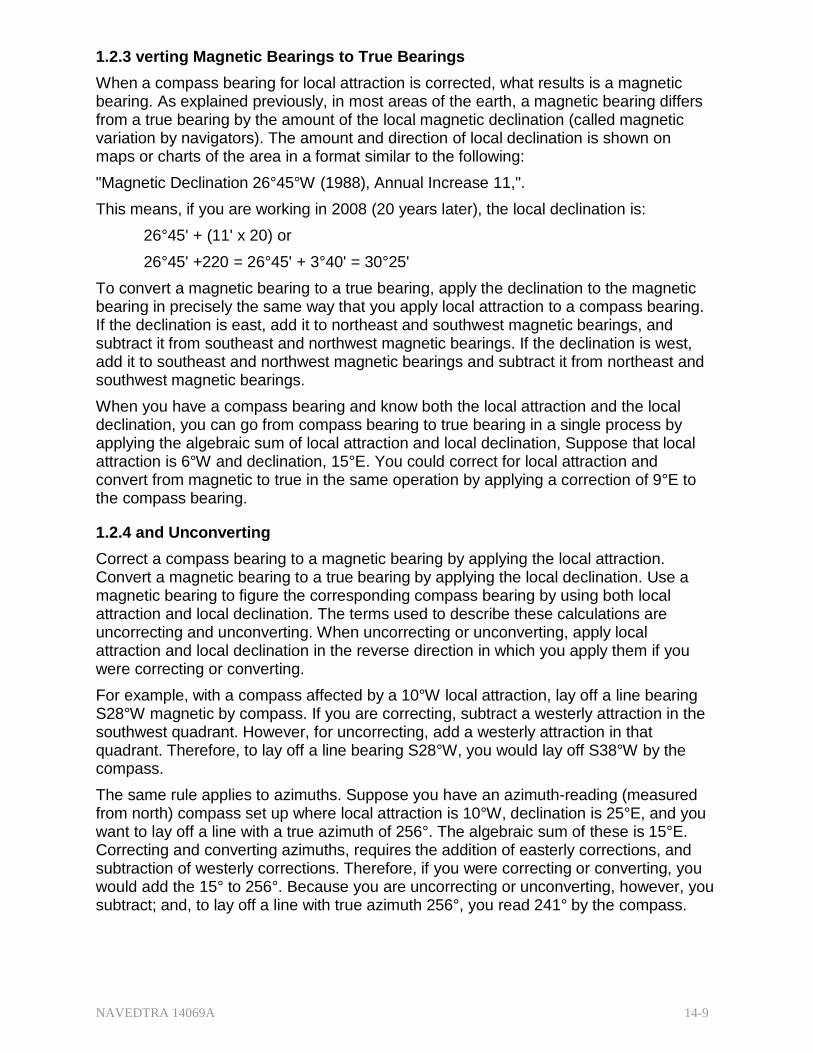
NAVEDTRA 14069A 14-9
1.2.3 verting Magnetic Bearings to True Bearings
When a compass bearing for local attraction is corrected, what results is a magnetic bearing. As explained previously, in most areas of the earth, a magnetic bearing differs from a true bearing by the amount of the local magnetic declination (called magnetic variation by navigators). The amount and direction of local declination is shown on maps or charts of the area in a format similar to the following:
"Magnetic Declination 26°45°W (1988), Annual Increase 11,".
This means, if you are working in 2008 (20 years later), the local declination is:
26°45' + (11' x 20) or
26°45' +220 = 26°45' + 3°40' = 30°25'
To convert a magnetic bearing to a true bearing, apply the declination to the magnetic bearing in precisely the same way that you apply local attraction to a compass bearing. If the declination is east, add it to northeast and southwest magnetic bearings, and subtract it from southeast and northwest magnetic bearings. If the declination is west, add it to southeast and northwest magnetic bearings and subtract it from northeast and southwest magnetic bearings.
When you have a compass bearing and know both the local attraction and the local declination, you can go from compass bearing to true bearing in a single process by applying the algebraic sum of local attraction and local declination, Suppose that local attraction is 6°W and declination, 15°E. You could correct for local attraction and convert from magnetic to true in the same operation by applying a correction of 9°E to the compass bearing.
1.2.4 and Unconverting
Correct a compass bearing to a magnetic bearing by applying the local attraction. Convert a magnetic bearing to a true bearing by applying the local declination. Use a magnetic bearing to figure the corresponding compass bearing by using both local attraction and local declination. The terms used to describe these calculations are uncorrecting and unconverting. When uncorrecting or unconverting, apply local attraction and local declination in the reverse direction in which you apply them if you were correcting or converting.
For example, with a compass affected by a 10°W local attraction, lay off a line bearing S28°W magnetic by compass. If you are correcting, subtract a westerly attraction in the southwest quadrant. However, for uncorrecting, add a westerly attraction in that quadrant. Therefore, to lay off a line bearing S28°W, you would lay off S38°W by the compass.
The same rule applies to azimuths. Suppose you have an azimuth-reading (measured from north) compass set up where local attraction is 10°W, declination is 25°E, and you want to lay off a line with a true azimuth of 256°. The algebraic sum of these is 15°E. Correcting and converting azimuths, requires the addition of easterly corrections, and subtraction of westerly corrections. Therefore, if you were correcting or converting, you would add the 15° to 256°. Because you are uncorrecting or unconverting, however, you subtract; and, to lay off a line with true azimuth 256°, you read 241° by the compass.
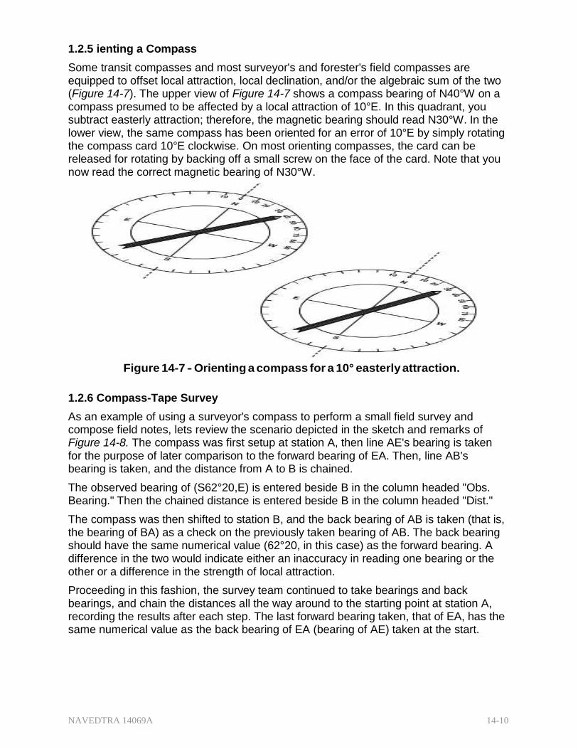
NAVEDTRA 14069A 14-10
1.2.5 ienting a Compass
Some transit compasses and most surveyor's and forester's field compasses are equipped to offset local attraction, local declination, and/or the algebraic sum of the two (Figure 14-7). The upper view of Figure 14-7 shows a compass bearing of N40°W on a compass presumed to be affected by a local attraction of 10°E. In this quadrant, you subtract easterly attraction; therefore, the magnetic bearing should read N30°W. In the lower view, the same compass has been oriented for an error of 10°E by simply rotating the compass card 10°E clockwise. On most orienting compasses, the card can be released for rotating by backing off a small screw on the face of the card. Note that you now read the correct magnetic bearing of N30°W.
Figure 14-7 - Orienting a compass for a 10° easterly attraction.
1.2.6 Compass-Tape Survey
As an example of using a surveyor's compass to perform a small field survey and compose field notes, lets review the scenario depicted in the sketch and remarks of Figure 14-8. The compass was first setup at station A, then line AE's bearing is taken for the purpose of later comparison to the forward bearing of EA. Then, line AB's bearing is taken, and the distance from A to B is chained.
The observed bearing of (S62°20,E) is entered beside B in the column headed "Obs. Bearing." Then the chained distance is entered beside B in the column headed "Dist."
The compass was then shifted to station B, and the back bearing of AB is taken (that is, the bearing of BA) as a check on the previously taken bearing of AB. The back bearing should have the same numerical value (62°20, in this case) as the forward bearing. A difference in the two would indicate either an inaccuracy in reading one bearing or the other or a difference in the strength of local attraction.
Proceeding in this fashion, the survey team continued to take bearings and back bearings, and chain the distances all the way around to the starting point at station A, recording the results after each step. The last forward bearing taken, that of EA, has the same numerical value as the back bearing of EA (bearing of AE) taken at the start.
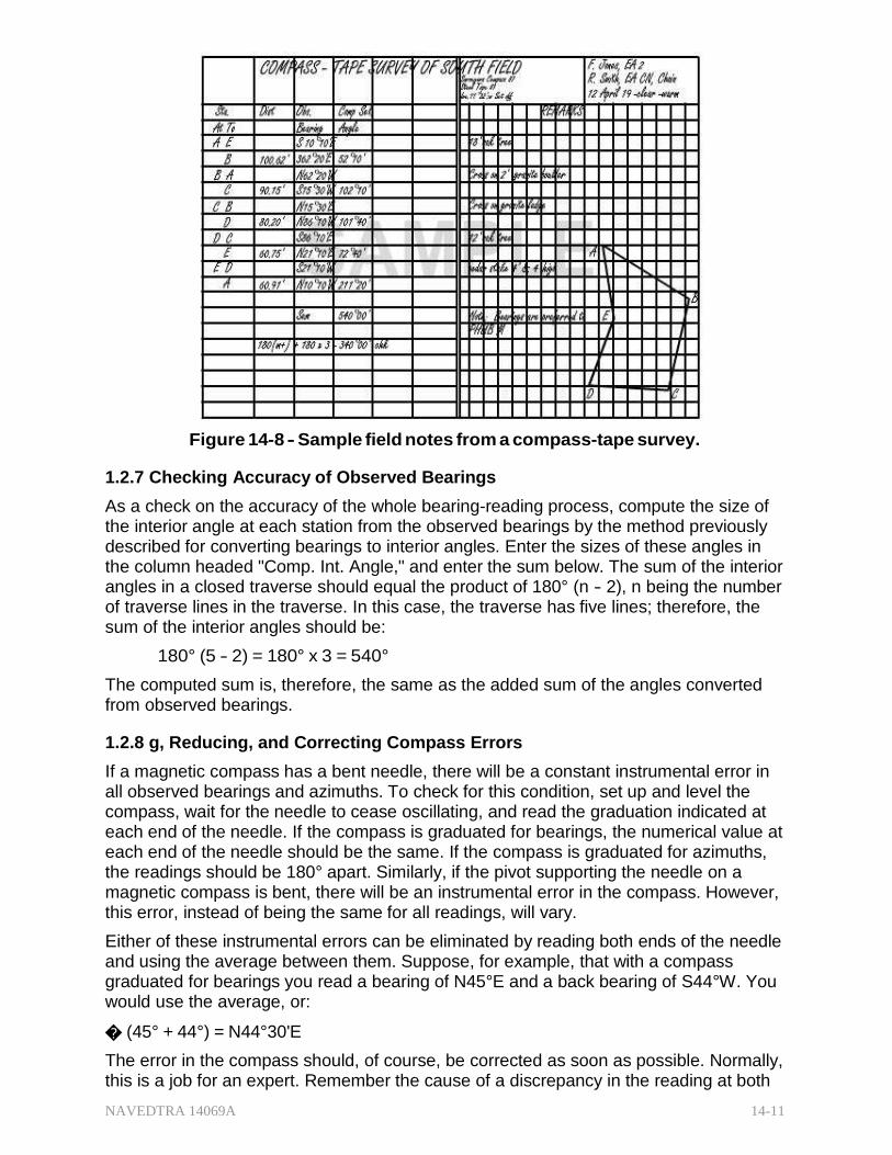
NAVEDTRA 14069A 14-11
Figure 14-8 - Sample field notes from a compass-tape survey. 1.2.7 Checking Accuracy of Observed Bearings
As a check on the accuracy of the whole bearing-reading process, compute the size of the interior angle at each station from the observed bearings by the method previously described for converting bearings to interior angles. Enter the sizes of these angles in the column headed "Comp. Int. Angle," and enter the sum below. The sum of the interior angles in a closed traverse should equal the product of 180° (n - 2), n being the number of traverse lines in the traverse. In this case, the traverse has five lines; therefore, the sum of the interior angles should be:
180° (5 - 2) = 180° x 3 = 540°
The computed sum is, therefore, the same as the added sum of the angles converted from observed bearings.
1.2.8 g, Reducing, and Correcting Compass Errors
If a magnetic compass has a bent needle, there will be a constant instrumental error in all observed bearings and azimuths. To check for this condition, set up and level the compass, wait for the needle to cease oscillating, and read the graduation indicated at each end of the needle. If the compass is graduated for bearings, the numerical value at each end of the needle should be the same. If the compass is graduated for azimuths, the readings should be 180° apart. Similarly, if the pivot supporting the needle on a magnetic compass is bent, there will be an instrumental error in the compass. However, this error, instead of being the same for all readings, will vary.
Either of these instrumental errors can be eliminated by reading both ends of the needle and using the average between them. Suppose, for example, that with a compass graduated for bearings you read a bearing of N45°E and a back bearing of S44°W. You would use the average, or:
� (45° + 44°) = N44°30'E
The error in the compass should, of course, be corrected as soon as possible. Normally, this is a job for an expert. Remember the cause of a discrepancy in the reading at both
NAVEDTRA 14069A 14-12
ends when there is one. It is more probable that the needle, rather than the pivot, is bent. After a bent needle is straightened, if a discrepancy still exists, then probably the pivot is bent too.
If a compass needle is sluggish-that is, if it moves unusually slowly in seeking magnetic north-it will probably come to rest a little off the magnetic meridian. The most common cause of sluggishness is weakening of the needle's magnetism. A needle may be demagnetized by drawing it over a bar magnet. The needle should be drawn from the center of the bar magnet toward the end, with the south end of the needle drawn over the north end of the magnet and vice versa. On each return stroke, lift the needle clear of the magnet.
Sometimes the cause of a sluggish needle is a blunt point on the pivot. This may be corrected by sharpening the pivot with a fine file. If the compass is not level when a bearing or azimuth is being read, the reading will be incorrect. A similar error exists if the compass is equipped with sighting vanes and one or more of them are bent. To check for bent compass vanes, set up and level the compass and then sight with the vanes on a plumb bob cord. The most common personal error the observer can make in compass work is MISREADING. This is caused by the observer's eye not being vertically above the compass at the time of the reading. Other common mistakes include reading a needle at the wrong end and setting off local attraction or declination in the wrong direction when orienting the compass.
1.3.0 Establishing Directions by Transit
Directions are similarly determined by the use of a transit. This can be done by measuring the size of the horizontal angle between the line whose direction is sought and a reference line. With a transit, however, you are expected to do this with considerably more accuracy and precision than with a surveyor's compass. Some of the basic procedures associated with the proper operation of the instrument will be discussed in the following paragraphs.
1.3.1 Setting up the Transit
The point at which the LOS, the horizontal axis, and the vertical axis of a transit meet is called the instrument center. The point on the ground over which the center of the instrument is placed is the instrument point, transit point, or station. A wooden stake or hub is usually marked with a tack when used as a transit station or point. To prevent jarring or displacement of the transit, avoid those stations with loose planking, soft or marshy ground, and other conditions that could cause the legs of the tripod to move.
The following steps are recommended when you are setting up a transit over a station point:
1. Center the instrument as closely as possible over the definite point by suspending a plumb line from a hook and chain beneath the instrument. Tie the plumb string with a slipknot, so that the height of the plumb is easily adjustable.
2. Move the tripod legs as necessary until the plumb bob is about 1/4 inch short of being over the tack, while maintaining a fairly level foot plate. Spread the tripod legs, and apply sufficient pressure to the legs to ensure their firmness in the ground. Make sure to loosen the wing nuts to release the static pressure before retightening.
3. Turn the plates so that each plate level is parallel to a pair of opposite leveling screws. (It is common practice to have a pair of opposite leveling screws in line
NAVEDTRA 14069A 14-13
with the approximate LOS.) Tighten the leveling screws, and then rotate opposing pairs of leveling screws either toward each other or away from each other until the plate bubbles are centered.
If the plumb bob is not directly over the center of the tack, loosen two adjacent leveling screws enough to free the shifting plate. Re-level the instrument if the bubbles become off-center. During breezy conditions, you may shield the plumb line with your body during setup. Sometimes in windy locations, it may be necessary to construct a wind shield.
Setting and leveling the transit rapidly requires a skill that develops through consistent practice. Take advantage of any opportunities to train and increase skills in handling surveying instruments. When setting up or operating a transit, do not forget:
1. The plate bubble follows the direction of the left thumb when you are manipulating the leveling screws.
2. Always check to see if the plumb bob is still over the point after leveling it. If the plumb bob has shifted, re-center the instrument.
3. While loosening the two adjacent leveling screws, shift the transit head laterally.
4. Always maintain contact between the leveling screw shoes and the foot plate.
5. Do not disturb the instrument setup until you are certain that all observations at that point are completed and roughly checked. Move the instrument from that setup only after checking with the party chief.
6. Before the transit is moved or taken up, center the instrument on the foot plate, roughly equalize the height of the leveling screws, clamp the upper motion (the lower motion may be tightened lightly), point the telescope vertically upward, and lightly tighten the vertical motion clamp
1.3.2 izontal Angles
The transit contains a graduated horizontal circle, referred to as the horizontal limb. The horizontal limb may be graduated clockwise from 0° through 360° (figure 13-9, view A), or clockwise from 0° through 360° and also in quadrants (figure 13-9, view B); or both clockwise and counterclockwise from 0° through 360° (figure 13-9, view C).
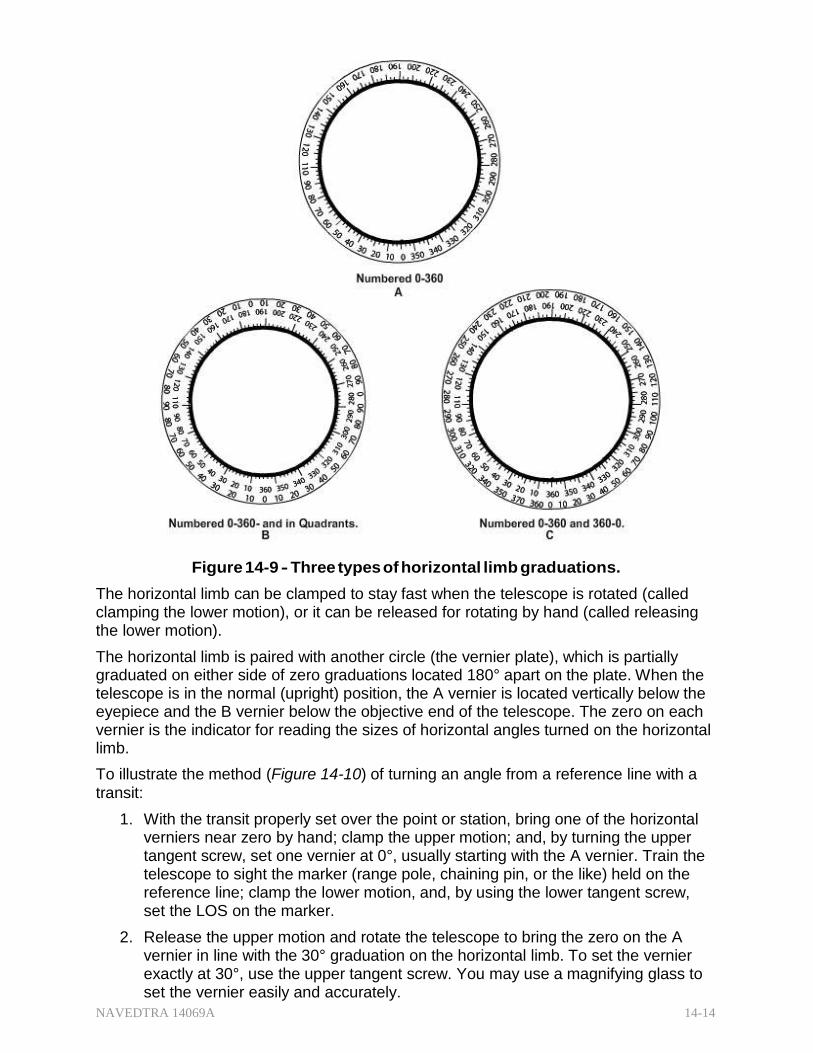
NAVEDTRA 14069A 14-14
Figure 14-9 - Three types of horizontal limb graduations.
The horizontal limb can be clamped to stay fast when the telescope is rotated (called clamping the lower motion), or it can be released for rotating by hand (called releasing the lower motion).
The horizontal limb is paired with another circle (the vernier plate), which is partially graduated on either side of zero graduations located 180° apart on the plate. When the telescope is in the normal (upright) position, the A vernier is located vertically below the eyepiece and the B vernier below the objective end of the telescope. The zero on each vernier is the indicator for reading the sizes of horizontal angles turned on the horizontal limb.
To illustrate the method (Figure 14-10) of turning an angle from a reference line with a transit:
1. With the transit properly set over the point or station, bring one of the horizontal verniers near zero by hand; clamp the upper motion; and, by turning the upper tangent screw, set one vernier at 0°, usually starting with the A vernier. Train the telescope to sight the marker (range pole, chaining pin, or the like) held on the reference line; clamp the lower motion, and, by using the lower tangent screw, set the LOS on the marker.
2. Release the upper motion and rotate the telescope to bring the zero on the A vernier in line with the 30° graduation on the horizontal limb. To set the vernier exactly at 30°, use the upper tangent screw. You may use a magnifying glass to set the vernier easily and accurately.
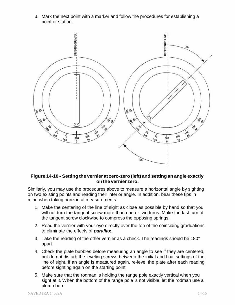
NAVEDTRA 14069A 14-15
3. Mark the next point with a marker and follow the procedures for establishing a point or station.
Figure 14-10 - Setting the vernier at zero-zero (left) and setting an angle exactly on the vernier zero.
Similarly, you may use the procedures above to measure a horizontal angle by sighting on two existing points and reading their interior angle. In addition, bear these tips in mind when taking horizontal measurements:
1. Make the centering of the line of sight as close as possible by hand so that you will not turn the tangent screw more than one or two turns. Make the last turn of the tangent screw clockwise to compress the opposing springs.
2. Read the vernier with your eye directly over the top of the coinciding graduations to eliminate the effects of parallax.
3. Take the reading of the other vernier as a check. The readings should be 180° apart.
4. Check the plate bubbles before measuring an angle to see if they are centered, but do not disturb the leveling screws between the initial and final settings of the line of sight. If an angle is measured again, re-level the plate after each reading before sighting again on the starting point.
5. Make sure that the rodman is holding the range pole exactly vertical when you sight at it. When the bottom of the range pole is not visible, let the rodman use a plumb bob.
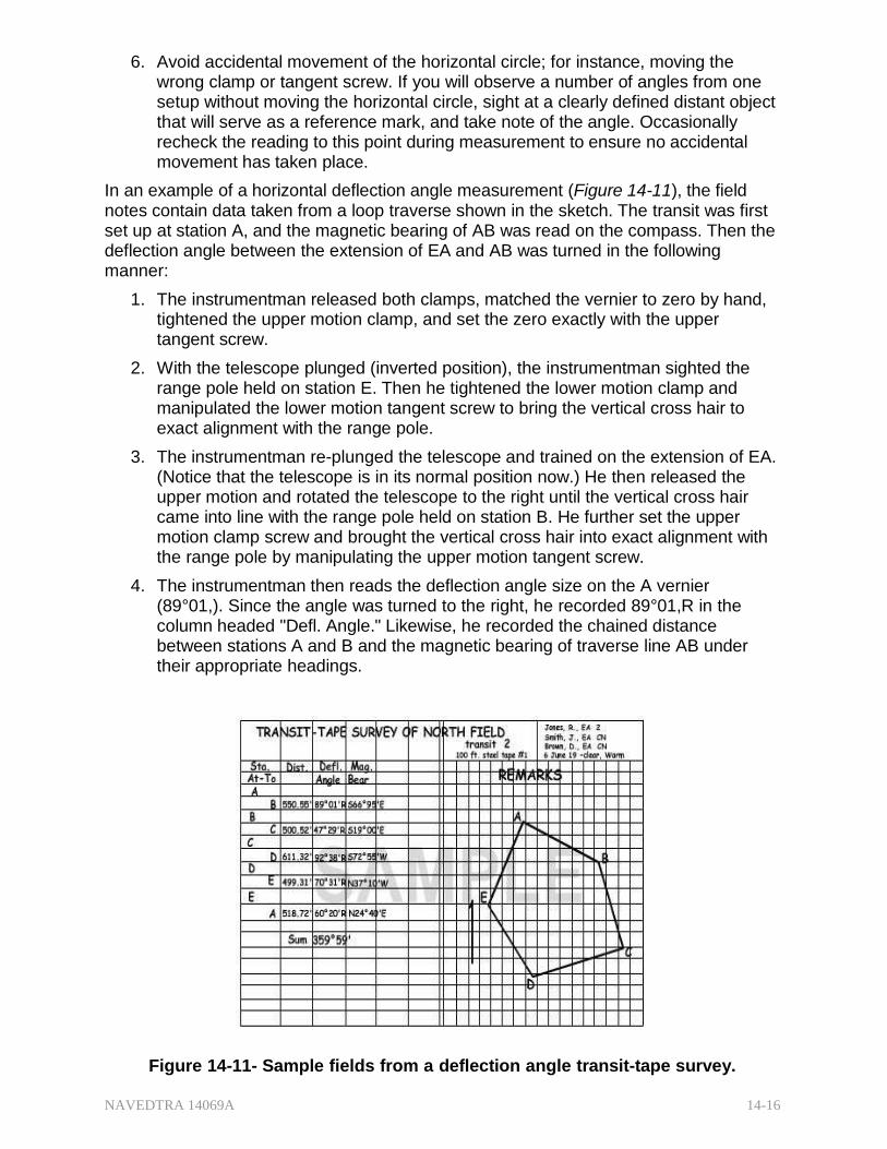
NAVEDTRA 14069A 14-16
6. Avoid accidental movement of the horizontal circle; for instance, moving the wrong clamp or tangent screw. If you will observe a number of angles from one setup without moving the horizontal circle, sight at a clearly defined distant object that will serve as a reference mark, and take note of the angle. Occasionally recheck the reading to this point during measurement to ensure no accidental movement has taken place.
In an example of a horizontal deflection angle measurement (Figure 14-11), the field notes contain data taken from a loop traverse shown in the sketch. The transit was first set up at station A, and the magnetic bearing of AB was read on the compass. Then the deflection angle between the extension of EA and AB was turned in the following manner:
1. The instrumentman released both clamps, matched the vernier to zero by hand, tightened the upper motion clamp, and set the zero exactly with the upper tangent screw.
2. With the telescope plunged (inverted position), the instrumentman sighted the range pole held on station E. Then he tightened the lower motion clamp and manipulated the lower motion tangent screw to bring the vertical cross hair to exact alignment with the range pole.
3. The instrumentman re-plunged the telescope and trained on the extension of EA. (Notice that the telescope is in its normal position now.) He then released the upper motion and rotated the telescope to the right until the vertical cross hair came into line with the range pole held on station B. He further set the upper motion clamp screw and brought the vertical cross hair into exact alignment with the range pole by manipulating the upper motion tangent screw.
4. The instrumentman then reads the deflection angle size on the A vernier (89°01,). Since the angle was turned to the right, he recorded 89°01,R in the column headed "Defl. Angle." Likewise, he recorded the chained distance between stations A and B and the magnetic bearing of traverse line AB under their appropriate headings.
Figure 14-11- Sample fields from a deflection angle transit-tape survey.
NAVEDTRA 14069A 14-17
The instrumentman uses the same method at each traverse station, working clockwise around the traverse to station E. The algebraic sum of the measured deflection angle (angles to the right considered as plus, to the left as minus) is 350°59,. For a closed traverse, the algebraic sum of the deflection angles from the standpoint of pure geometry is 360°00,. Therefore, there is an angular error of disclosure here of 0°01,. This small error would probably be considered a normal error. A large variance would indicate a larger mistake made in the measurements. In this example, the general accuracy of all the angular measurements was checked by comparing the sum of the deflection angles with the theoretical sum. The accuracy of single angular measurement can be checked by closing the horizon. The method is based on the theoretical sum of all the angles around a point being 360°00,.
The field notes (Figure 14-12) show the procedure for closing the horizon. The transit was set up at station A, and angle BAC was turned, measuring 51°15,. Then the angle from AC clockwise around to AB was turned, measuring 308°45,. The sum of the two angles is 360°00,. The angular error of closure is therefore 0°00,, meaning that perfect closure is obtained.
Figure 14-12 - Sample field notes for closing the horizon. 1.3.3 Measuring Vertical Angles
The vertical circle and the vertical vernier of a transit are used for measuring vertical angles. A vertical angle is the angle measured vertically from a horizontal plane of reference (Figure 14-13, view A). When the telescope is pointed in the horizontal plane (when the telescope is level), the value of the vertical angle is zero. When the telescope is pointed up at a higher feature (elevated), the vertical angle increases from zero and is a plus vertical angle or angle of elevation. These values increase from 0° to +90° when the telescope is pointed straight up. As the telescope is depressed (pointed down), the angle increases in numerical value. A depressed telescope reading, showing that it is below the horizontal plane, is a minus vertical angle or angle of depression. These numerical values increase from 00 to -90° when the telescope is pointed straight down.
To measure vertical angles, set the transit upon a definite point and level it. The plate bubbles must be centered carefully, especially for transits that have a fixed vertical
NAVEDTRA 14069A 14-18
vernier. Turn the LOS to approximately the point that the horizontal axis is clamped. Then, bring the horizontal cross hair to the point by means of the telescope tangent screw. Read the angle on the vertical limb using the vertical vernier.
On a transit with a movable vertical vernier, the vernier is equipped with a control level. The telescope is centered on the point as previously described, but the vernier bubble is centered before the angle is read.
The zenith is an imaginary point overhead where the extension of the plumb line will intersect an assumed sphere on which the stars appear projected. The equivalent point, directly below the zenith, is the nadir. Using the zenith permits reading angles in a vertical plane without using a plus or a minus. Theodolites have a vertical scale reading zero when the telescope is pointed at the zenith instead of in a horizontal plane. With the telescope in a direct position and pointed straight up, the reading is 0°; on a horizontal line, the reading is 90°; and straight down, 180°. When measuring vertical angles with the theodolites (Figure 14-13, view B), read the angle of elevation with values less than 90°and the angle of depression with values greater than 90°. These angle measurements with the zenith as the zero value are called the zenith distances. Double zenith distances are observations made with the telescope directly and reversed to eliminate errors caused by the inclination of the vertical axis and the collimation of the vertical circle. Zenith distance is used to measure vertical angles involving trigonometric leveling and in astronomical observations.
Figure 14-13 - Vertical angles and zenith
NAVEDTRA 14069A 14-19
1.3.4 Measuring Angles by Repetition
There is a significant distinction between precision and accuracy. A transit on which angles can be measured to the nearest 20 second is more precise than one that can measure only to the nearest 1 minute. However, this transit is not necessarily more accurate.
The inherent angular precision of a transit is increased by the process of repetition. To illustrate this principle, suppose that with a one minute transit you turn the angle between two lines in the field and read 45°00,. The inherent error in the transit is 1,; therefore, the true size of this angle is somewhere between 44°59,30,, and 45°00,30,,. For example, when using repetition, you leave the upper motion locked but release the lower motion. The horizontal limb will now rotate with the telescope, holding the reading of 45°00,. You plunge the telescope, train again on the initial line of the angle, and again turn the angle. You have now doubled the angle. The A vernier should read approximately 90°00,. For this second reading, the inherent error in the transit is still one minute, but the angle indicated on the A vernier is about twice the size of the actual angle measured. The effect of this is to halve the total possible error. This error was originally plus or minus 30 seconds. Now, the error is plus or minus only 15 seconds.
If you measure this angle a total of six times, the total possible error will be reduced to one-sixth of 30 seconds, or plus or minus 5 seconds. In theory, you could go on repeating the angle and increasing the precision indefinitely. In actual practice, because of lost motion in the instrument and accidental errors, it is not necessary to repeat the angle more than six times.
The observation may be taken alternately with the telescope plunged before each subsequent observation. But a much simpler way is to take the first half of the observations with the telescope in the normal position, the other half, in an inverted position. Using the details of the previous example, the first three readings may be taken when the telescope is in its normal position; the last three when it is in its reversed position. To avoid the effect of tripod twist, after each repetition, rotate the instrument on its lower motion in the same direction that you turned it during the measurement; that is, the direction of movement should always be either clockwise or counterclockwise. Measuring angles by repetition eliminates certain possible instrumental errors, such as those caused by eccentricity and by non-adjustment of the horizontal axis.
Review the field notes for the angle around a station, repeated six times (Figure 14-14). The angle BAC was measured six times, and the angle closing the horizon around station A was also measured six times. The first measurement is not a true repeat, but it is counted as one in the column headed "No. Rep." (number of repetitions). With the transit first trained on B and the zeros matched, the plate reading was 00°00,. This is recorded beside B in the column headed "Plate Reading". The upper motion clamp was then released, the telescope was trained on C, and a plate reading of 82°45, was obtained. This reading is recorded next to the figure 1" (for "1st repetition") in the column headed "No. Rep." The measurement of angle BAC was then repeated five more times. After the final measurement, the plate reading was 136°28,. This plate reading is recorded as the sixth repetition.
To get the mean angle, divide some number, or figure, by the total number of repetitions. To determine which figure to use, first multiply the initial measurement by the total number of repetitions. In this case, as follows:
82°45' x 6 = 496°30'
NAVEDTRA 14069A 14-20
Figure 14-14 - Notes for the angle around a station, repeated six times.
Next, determine the largest multiple of 360° that can be subtracted from the above product. Obviously, the only multiple of 360° that can be subtracted from 496°30, is 360°. This multiple is then added to the final measurement to obtain the figure that is to be divided by the total number of repetitions. In this example:
136°28' + 360° = 496°28'
The mean angle then is
496°28' 6 = 82°44'40"
Enter this in the column headed "Mean Angle". The following computation shows that you should use the same method to obtain the mean closing angle.
277°15' x 6 = 1663°30'
360° x 4 = 1440° (largest multiple of 360°
223°32' + 1440 = 1663°32'
1663°32' 6 = 277°15'20"
In the example shown above, the sum of the mean angle (82°44,40,,) and the mean closing angle (277°15,20,,) equals 360°00,00,,. This reflects perfect closure. In actual practice, perfect angle closure would be unlikely.
1.4.0 Running a Distance (Line)
It is often necessary to extend a straight line marked by two points on the ground. Which method is used depends on whether or not there are obstacles in the line ahead, and, if so, whether the obstacles are small or large.
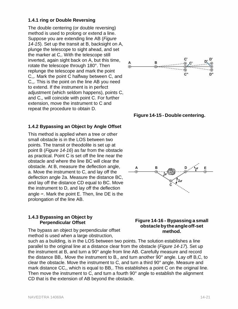
NAVEDTRA 14069A 14-21
1.4.1 ring or Double Reversing
The double centering (or double reversing) method is used to prolong or extend a line. Suppose you are extending line AB (Figure 14-15). Set up the transit at B, backsight on A, plunge the telescope to sight ahead, and set the marker at C,. With the telescope still inverted, again sight back on A, but this time, rotate the telescope through 180°. Then replunge the telescope and mark the point C,,. Mark the point C halfway between C, and C,,. This is the point on the line AB you need to extend. If the instrument is in perfect adjustment (which seldom happens), points C, and C,, will coincide with point C. For further extension, move the instrument to C and repeat the procedure to obtain D.
1.4.2 Bypassing an Object by Angle Offset
This method is applied when a tree or other small obstacle is in the LOS between two points. The transit or theodolite is set up at point B (Figure 14-16) as far from the obstacle as practical. Point C is set off the line near the obstacle and where the line BC will clear the obstacle. At B, measure the deflection angle, a. Move the instrument to C, and lay off the deflection angle 2a. Measure the distance BC, and lay off the distance CD equal to BC. Move the instrument to D, and lay off the deflection
angle . Mark the point E. Then, line DE is the prolongation of the line AB.
1.4.3 Bypassing an Object by
Perpendicular Offset
The bypass an object by perpendicular offset method is used when a large obstruction,
Figure 14-15 - Double centering.
Figure 14-16 - Bypassing a small obstacle by the angle off-set
method.
such as a building, is in the LOS between two points. The solution establishes a line parallel to the original line at a distance clear from the obstacle (Figure 14-17). Set up the instrument at B, and turn a 90° angle from line AB. Carefully measure and record the distance BB,. Move the instrument to B,, and turn another 90° angle. Lay off B,C, to clear the obstacle. Move the instrument to C, and turn a third 90° angle. Measure and mark distance CC,, which is equal to BB,. This establishes a point C on the original line. Then move the instrument to C, and turn a fourth 90° angle to establish the alignment CD that is the extension of AB beyond the obstacle.
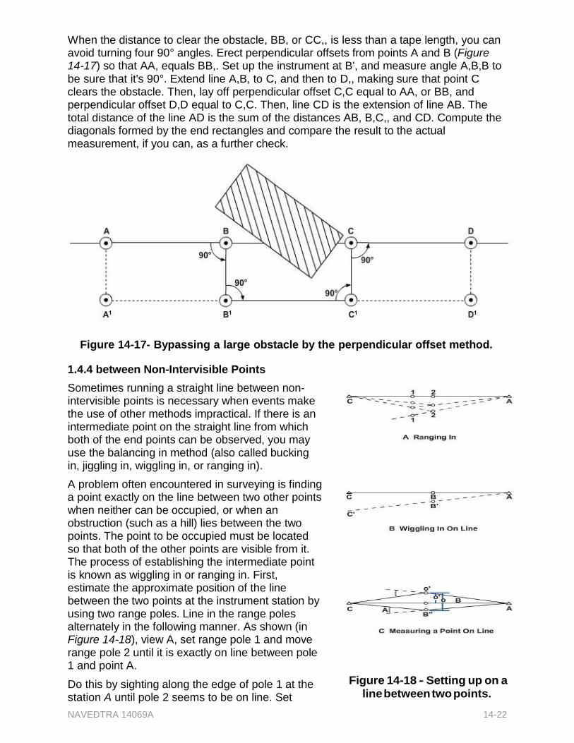
NAVEDTRA 14069A 14-22
When the distance to clear the obstacle, BB, or CC,, is less than a tape length, you can avoid turning four 90° angles. Erect perpendicular offsets from points A and B (Figure 14-17) so that AA, equals BB,. Set up the instrument at B', and measure angle A,B,B to be sure that it's 90°. Extend line A,B, to C, and then to D,, making sure that point C clears the obstacle. Then, lay off perpendicular offset C,C equal to AA, or BB, and perpendicular offset D,D equal to C,C. Then, line CD is the extension of line AB. The total distance of the line AD is the sum of the distances AB, B,C,, and CD. Compute the diagonals formed by the end rectangles and compare the result to the actual measurement, if you can, as a further check.
Figure 14-17- Bypassing a large obstacle by the perpendicular offset method.
1.4.4 between Non-Intervisible Points
Sometimes running a straight line between non- intervisible points is necessary when events make the use of other methods impractical. If there is an intermediate point on the straight line from which both of the end points can be observed, you may use the balancing in method (also called bucking in, jiggling in, wiggling in, or ranging in).
A problem often encountered in surveying is finding a point exactly on the line between two other points when neither can be occupied, or when an obstruction (such as a hill) lies between the two points. The point to be occupied must be located so that both of the other points are visible from it. The process of establishing the intermediate point is known as wiggling in or ranging in. First, estimate the approximate position of the line between the two points at the instrument station by using two range poles. Line in the range poles alternately in the following manner. As shown (in Figure 14-18), view A, set range pole 1 and move range pole 2 until it is exactly on line between pole 1 and point A.
Do this by sighting along the edge of pole 1 at the station A until pole 2 seems to be on line. Set
Figure 14-18 - Setting up on a
line between two points.
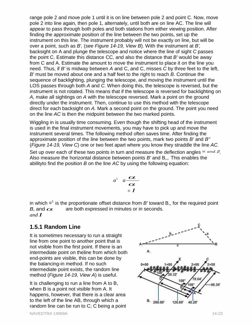
NAVEDTRA 14069A 14-23
range pole 2 and move pole 1 until it is on line between pole 2 and point C. Now, move pole 2 into line again, then pole 1, alternately, until both are on line AC. The line will appear to pass through both poles and both stations from either viewing position. After finding the approximate position of the line between the two points, set up the instrument on this line. The instrument probably will not be exactly on line, but will be over a point, such as B', (see Figure 14-19, View B). With the instrument at B', backsight on A and plunge the telescope and notice where the line of sight C passes the point C. Estimate this distance CC, and also the distance that B' would be away from C and A. Estimate the amount to move the instrument to place it on the line you need. Thus, if B' is midway between A and C, and C, misses C by three feet to the left, B' must be moved about one and a half feet to the right to reach B. Continue the sequence of backlighting, plunging the telescope, and moving the instrument until the LOS passes through both A and C. When doing this, the telescope is reversed, but the instrument is not rotated. This means that if the telescope is reversed for backlighting on A, make all sightings on A with the telescope reversed. Mark a point on the ground directly under the instrument. Then, continue to use this method with the telescope direct for each backsight on A. Mark a second point on the ground. The point you need on the line AC is then the midpoint between the two marked points.
Wiggling in is usually time consuming. Even though the shifting head of the instrument is used in the final instrument movements, you may have to pick up and move the instrument several times. The following method often saves time. After finding the approximate position of the line between the two points, mark two points B' and B'' (Figure 14-19, View C) one or two feet apart where you know they straddle the line AC.
Set up over each of these two points in turn and measure the deflection angles . Also measure the horizontal distance between points B' and B,,. This enables the abilityto find the position B on the line AC by using the following equation:
a1 a
in which is the proportionate offset distance from B' toward B,, for the required point
B, and
and
are both expressed in minutes or in seconds.
1.5.1 Random Line
It is sometimes necessary to run a straight line from one point to another point that is not visible from the first point. If there is an intermediate point on theline from which both end-points are visible, this can be done by the balancing-in method. If no such intermediate point exists, the random line method (Figure 14-19, View A) is useful.
It is challenging to run a line from A to B, when B is a point not visible from A. It happens, however, that there is a clear area to the left of the line AB, through which a random line can be run to C; C being a point

NAVEDTRA 14069A 14-24
visible from A and B. Figure 14-19 - Random line method for locating intermediate stations.
NAVEDTRA 14069A 14-25
To train a transit set up at A on B, knowing the size of the angle at A is necessary. You can measure side b and side a, and you can measure the angle at C. Therefore, you have a triangle, of which you know two sides and the included angle. You can solve this triangle for angle A by:
Determining the size of side c by the law of cosines, then determining the size of angle A by the law of sines
Solving for angle A by reducing to two right triangles
Suppose you find that angle A measures 16°35,. To train a transit at A on B, you would simply train on C and then turn 16°35, to the right.
You may also use the random line method to locate intermediate stations on a survey line. As shown in Figure 14-19, View B, stations 0 + 00 and 2 + 50, now separated by a grove of trees, were placed at some time in the past. You need to locate stations 1 + 00 and 2 + 00, which lie among the trees.
Run a line at random from station 0 + 00 until you can see station 2 + 50 from some point, A, on the line. The transitman measures the angle at A and finds it to be 108°00,. The distances from A to stations 0 + 00 and 2 + 50 are chained and found to be 201.00 feet and 98.30 feet. With this information, it is now possible to locate the intermediate stations between stations 0 + 00 and 2 + 50. The distances AB and AD can be computed by ratio and proportion, as follows:
AB
50
250
x 201.0 40.20
ft.
and AB 150
x 201.0 120.60 250
ft.
Lay off these distances on the random line from point A toward station 0 + 00. The instrumentman then occupies points B and D; turns the same angle, 108°00,, that he or she measured at point A and establishes points C and E on lines from points B and D through the stations being sought. The distances are computed by similar triangles as follows:
B to station 2 00(BC) 200
x 98.3 ft 78.64 ft 250
D to station 1 00(DE) 100
x 98.3 ft 39.32 ft 250
1.6.0 Tying In a Point
Determining the horizontal location of a point or points with reference to a station, or two stations, on a traverse line is commonly termed tying the point. The next several paragraphs present various methods used in the process.
Figure 14-20 - Swing offset method of locating points.
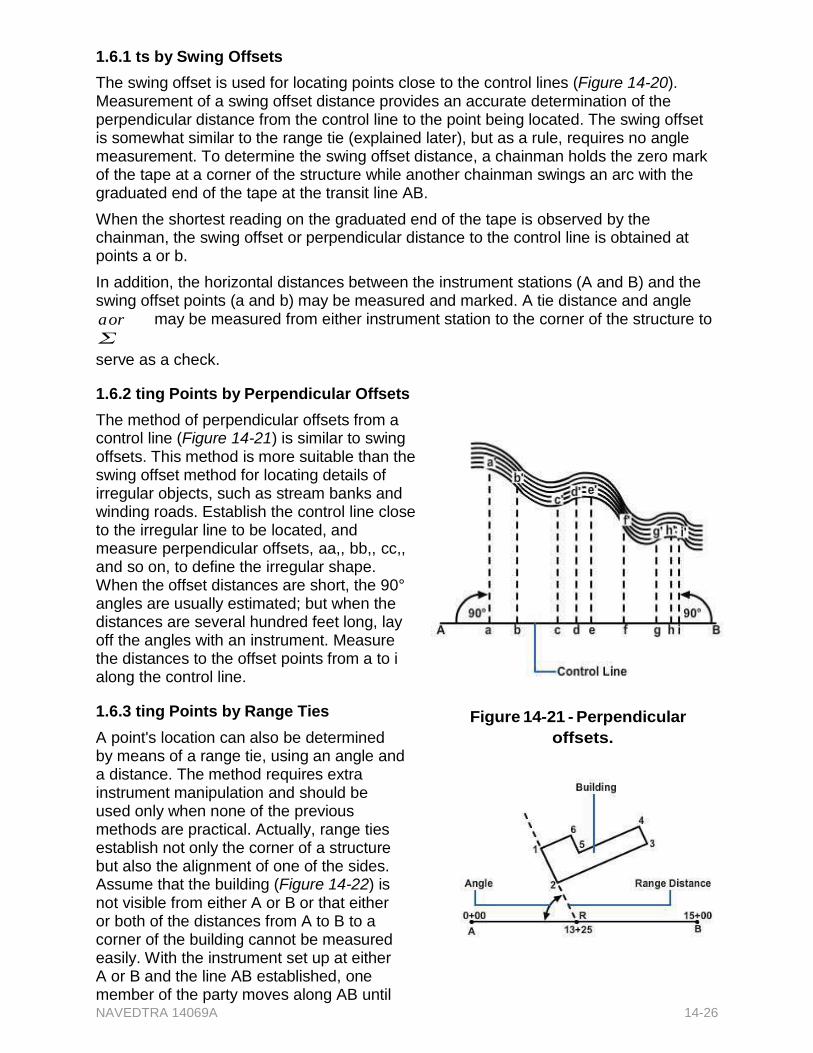
NAVEDTRA 14069A 14-26
1.6.1 ts by Swing Offsets
The swing offset is used for locating points close to the control lines (Figure 14-20). Measurement of a swing offset distance provides an accurate determination of the perpendicular distance from the control line to the point being located. The swing offset is somewhat similar to the range tie (explained later), but as a rule, requires no angle measurement. To determine the swing offset distance, a chainman holds the zero mark of the tape at a corner of the structure while another chainman swings an arc with the graduated end of the tape at the transit line AB.
When the shortest reading on the graduated end of the tape is observed by the chainman, the swing offset or perpendicular distance to the control line is obtained at points a or b.
In addition, the horizontal distances between the instrument stations (A and B) and the swing offset points (a and b) may be measured and marked. A tie distance and angle
a or
may be measured from either instrument station to the corner of the structure to
serve as a check.
1.6.2 ting Points by Perpendicular Offsets
The method of perpendicular offsets from a control line (Figure 14-21) is similar to swing offsets. This method is more suitable than the swing offset method for locating details of irregular objects, such as stream banks and winding roads. Establish the control line close to the irregular line to be located, and measure perpendicular offsets, aa,, bb,, cc,, and so on, to define the irregular shape. When the offset distances are short, the 90° angles are usually estimated; but when the distances are several hundred feet long, lay off the angles with an instrument. Measure the distances to the offset points from a to i along the control line.
1.6.3 ting Points by Range Ties
A point's location can also be determined by means of a range tie, using an angle and a distance. The method requires extra instrument manipulation and should be used only when none of the previous methods are practical. Actually, range ties establish not only the corner of a structure but also the alignment of one of the sides. Assume that the building (Figure 14-22) is not visible from either A or B or that either or both of the distances from A to B to a corner of the building cannot be measured easily. With the instrument set up at either A or B and the line AB established, one member of the party moves along AB until
Figure 14-21 - Perpendicular
offsets.

NAVEDTRA 14069A 14-27
Figure 14-22 - Range ties.
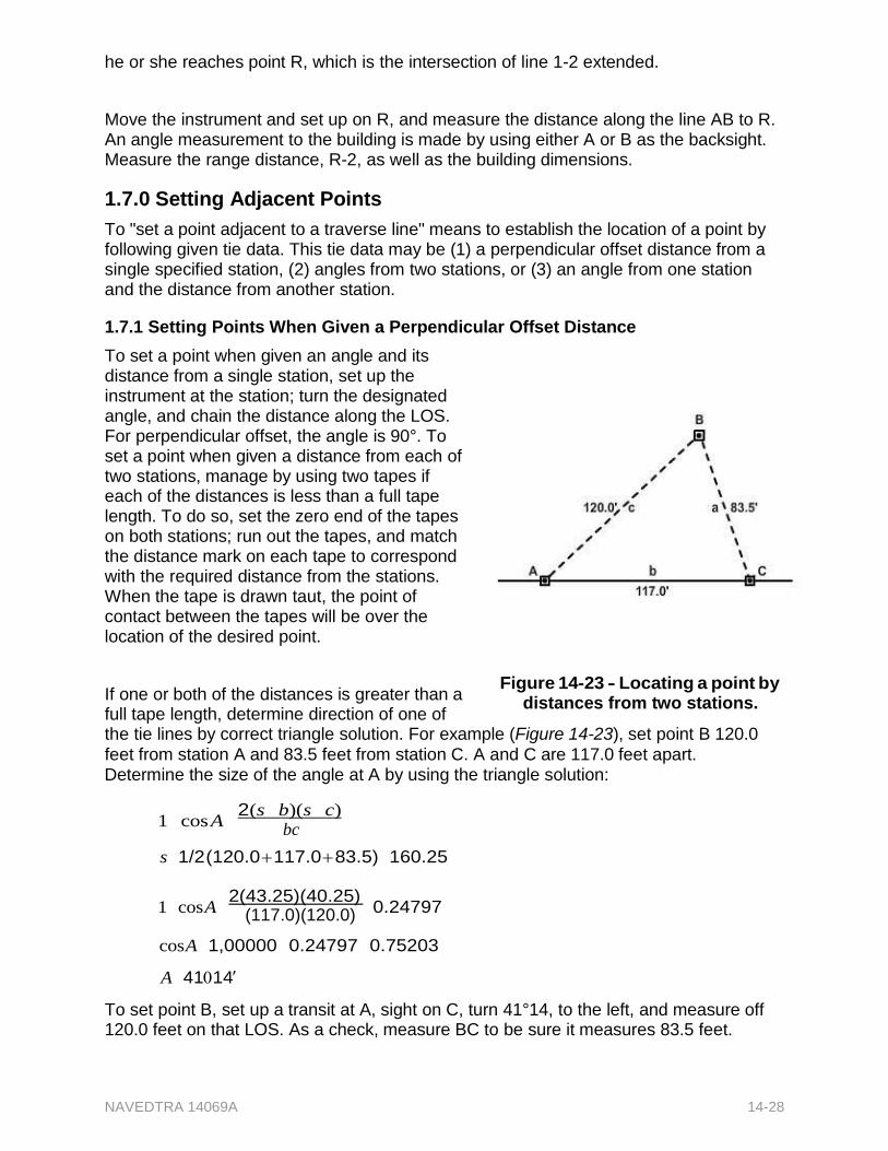
NAVEDTRA 14069A 14-28
he or she reaches point R, which is the intersection of line 1-2 extended.
Move the instrument and set up on R, and measure the distance along the line AB to R. An angle measurement to the building is made by using either A or B as the backsight. Measure the range distance, R-2, as well as the building dimensions.
1.7.0 Setting Adjacent Points
To "set a point adjacent to a traverse line" means to establish the location of a point by following given tie data. This tie data may be (1) a perpendicular offset distance from a single specified station, (2) angles from two stations, or (3) an angle from one station and the distance from another station.
1.7.1 Setting Points When Given a Perpendicular Offset Distance
To set a point when given an angle and its distance from a single station, set up the instrument at the station; turn the designated angle, and chain the distance along the LOS. For perpendicular offset, the angle is 90°. To set a point when given a distance from each of two stations, manage by using two tapes if each of the distances is less than a full tape length. To do so, set the zero end of the tapes on both stations; run out the tapes, and match the distance mark on each tape to correspond with the required distance from the stations. When the tape is drawn taut, the point of contact between the tapes will be over the location of the desired point.
If one or both of the distances is greater than a full tape length, determine direction of one of
Figure 14-23 - Locating a point by distances from two stations.
the tie lines by correct triangle solution. For example (Figure 14-23), set point B 120.0 feet from station A and 83.5 feet from station C. A and C are 117.0 feet apart. Determine the size of the angle at A by using the triangle solution:
1 cos A 2(s b)(s c)
bc
s 1/2 (120.0 117.0 83.5) 160.25
1 cos A 2(43.25)(40.25)
0.24797
(117.0)(120.0)
cos A 1,00000 0.24797 0.75203
A 4114
To set point B, set up a transit at A, sight on C, turn 41°14, to the left, and measure off 120.0 feet on that LOS. As a check, measure BC to be sure it measures 83.5 feet.
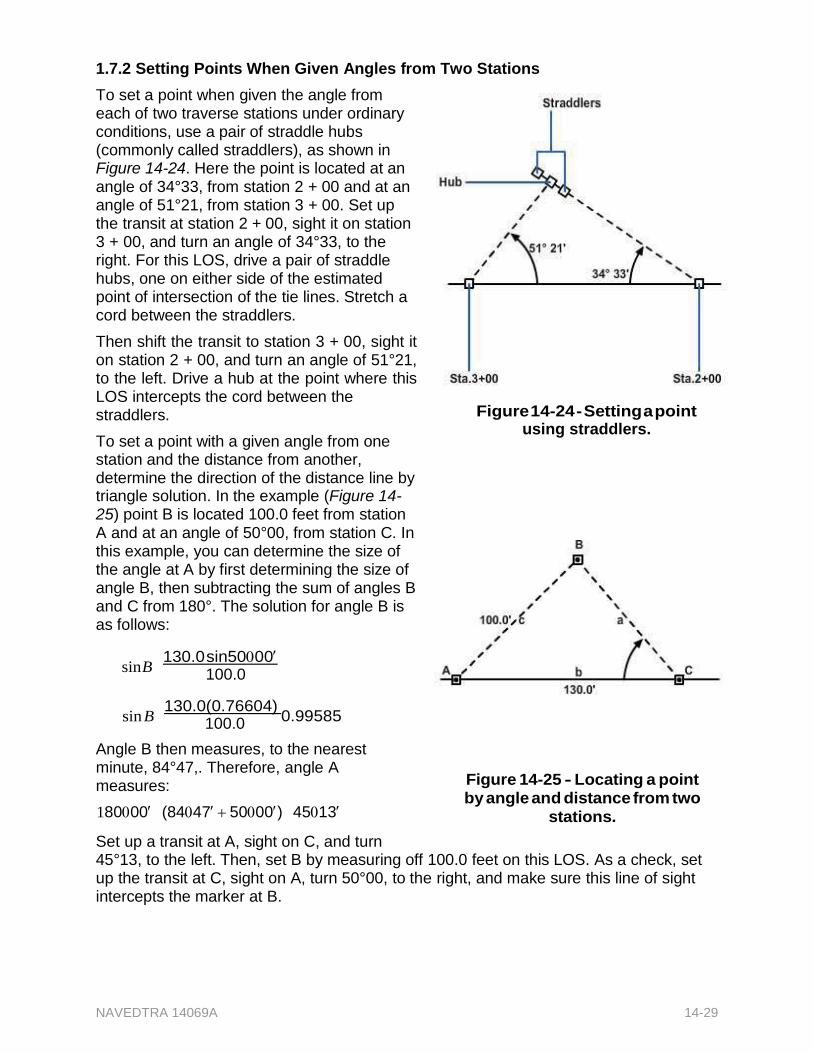
NAVEDTRA 14069A 14-29
1.7.2 Setting Points When Given Angles from Two Stations
To set a point when given the angle from each of two traverse stations under ordinary conditions, use a pair of straddle hubs (commonly called straddlers), as shown in Figure 14-24. Here the point is located at an angle of 34°33, from station 2 + 00 and at an angle of 51°21, from station 3 + 00. Set up the transit at station 2 + 00, sight it on station 3 + 00, and turn an angle of 34°33, to the right. For this LOS, drive a pair of straddle hubs, one on either side of the estimated point of intersection of the tie lines. Stretch a cord between the straddlers.
Then shift the transit to station 3 + 00, sight it on station 2 + 00, and turn an angle of 51°21, to the left. Drive a hub at the point where this LOS intercepts the cord between the straddlers.
To set a point with a given angle from one station and the distance from another, determine the direction of the distance line by triangle solution. In the example (Figure 14- 25) point B is located 100.0 feet from station A and at an angle of 50°00, from station C. In this example, you can determine the size of the angle at A by first determining the size of angle B, then subtracting the sum of angles B and C from 180°. The solution for angle B is as follows:
sin B 130.0 sin5000
100.0
sin B 130.0(0.76604)
0.99585
100.0
Angle B then measures, to the nearest minute, 84°47,. Therefore, angle A measures:
18000(84475000) 4513
Set up a transit at A, sight on C, and turn
Figure 14-24 - Setting a point using straddlers.
Figure 14-25 - Locating a point by angle and distance from two
stations.
45°13, to the left. Then, set B by measuring off 100.0 feet on this LOS. As a check, set up the transit at C, sight on A, turn 50°00, to the right, and make sure this line of sight intercepts the marker at B.
NAVEDTRA 14069A 14-30
Test your Knowledge (Select the Correct Response)
1. What is the size of the deflection angle between traverse lines BC and CD in the figure?
A. 60° B. 90° C. 105° D. 120°
2. What is the approximate true bearing of the object if the local declination is 10°W
and the local attraction is 20E?
A. S80° B. S100°W C. N80°W D. N100°E
3. What are the respective bearings of the traverse lines OP
in A and B in the figure?
A. N30°E and S30°W B. S30°W and N30°W C. S30°E and N30°E D. N30°E and S30°E
2.0.0 TRANSIT-TAPE SURVEY
The exact method used in transit-tape surveying may vary slightly depending upon the nature of the survey, the intended purpose, the command or unit policy, and the preferences of the survey party chief. The procedures presented in this section are customary methods described in general terms.
2.1.0 Selecting Points for Marking
All points where a traverse changes direction are marked, usually with a hub that locates the station exactly, plus a guard stake on which the station of the change-of- direction point is inscribed, such as 12 + 35. In the expression "station 12 + 35," the 12 is called the full station and the 35 is called the plus.
The points intended to be tied to the traverse or set in the vicinity of the traverse are usually selected and marked or set as the traverse is run. Select and mark the corresponding tie stations on the traverse at the same time. The first consideration in selecting tie stations is visibility, meaning that tie stations and the point to be tied or set must be intervisible. The next is permanency (not easily disturbed). Last is the strength of the intersection, which generally means that the angle between two tie lines should be as close to 90° as possible. The more acute or obtuse the angle is between tie lines, the less accurate the location of the point defined by their intersection.
2.2.0 Identifying Party Personnel
A typical transit-tape survey party contains two chainmen, a transitman, a recorder (sometimes the transitman or party chief doubles as recorder), a party chief (who may
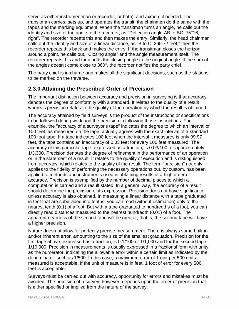
NAVEDTRA 14069A 14-31
serve as either instrumentman or recorder, or both), and axmen, if needed. The transitman carries, sets up, and operates the transit; the chainmen do the same with the tapes and the marking equipment. When the transitman turns an angle, he calls out the identity and size of the angle to the recorder, as "Deflection angle AB to BC, 75°16,, right". The recorder repeats this and then makes the entry. Similarly, the head chainman calls out the identity and size of a linear distance, as "B to C, 265.72 feet;" then the recorder repeats this back and makes the entry. If the transitman closes the horizon around a point, he calls out, "Closing angle" and the angle measurement itself. The recorder repeats this and then adds the closing angle to the original angle. If the sum of the angles doesn't come close to 360°, the recorder notifies the party chief.
The party chief is in charge and makes all the significant decisions, such as the stations to be marked on the traverse.
2.3.0 Attaining the Prescribed Order of Precision
The important distinction between accuracy and precision in surveying is that accuracy denotes the degree of conformity with a standard. It relates to the quality of a result whereas precision relates to the quality of the operation by which the result is obtained.
The accuracy attained by field surveys is the product of the instructions or specifications to be followed during work and the precision in following those instructions. For example, the "accuracy of a surveyor's tape" indicates the degree to which an interval of 100 feet, as measured on the tape, actually agrees with the exact interval of a standard 100 foot tape. If a tape indicates 100 feet when the interval it measures is only 99.97 feet, the tape contains an inaccuracy of 0.03 feet for every 100 feet measured. The accuracy of this particular tape, expressed as a fraction, is 0.03/100, or approximately 1/3,300. Precision denotes the degree of refinement in the performance of an operation or in the statement of a result. It relates to the quality of execution and is distinguished from accuracy, which relates to the quality of the result. The term "precision" not only applies to the fidelity of performing the necessary operations but, by custom, has been applied to methods and instruments used in obtaining results of a high order of accuracy. Precision is exemplified by the number of decimal places to which a computation is carried and a result stated. In a general way, the accuracy of a result should determine the precision of its expression. Precision does not have significance unless accuracy is also obtained. In measuring a linear distance with a tape graduated in feet that are subdivided into tenths, you can read (without estimation) only to the nearest tenth (0.1) of a foot. But with a tape graduated to hundredths of a foot, you can directly read distances measured to the nearest hundredth (0.01) of a foot. The apparent nearness of the second tape will be greater; that is, the second tape will have a higher precision.
Nature does not allow for perfectly precise measurement. There is always some built-in and/or inherent error, amounting to the size of the smallest graduation. Precision for the first tape above, expressed as a fraction, is 0.1/100 or 1/1,000 and for the second tape, 1/10,000. Precision in measurements is usually expressed in a fractional form with unity as the numerator, indicating the allowable error within a certain limit as indicated by the denominator, such as 1/500. In this case, a maximum error of 1 unit per 500 units measured is acceptable. If the unit of measure is in feet, 1 foot of error for every 500 feet is acceptable.
Surveys must be carried out with accuracy, opportunity for errors and mistakes must be avoided. The precision of a survey, however, depends upon the order of precision that is either specified or implied from the nature of the survey.
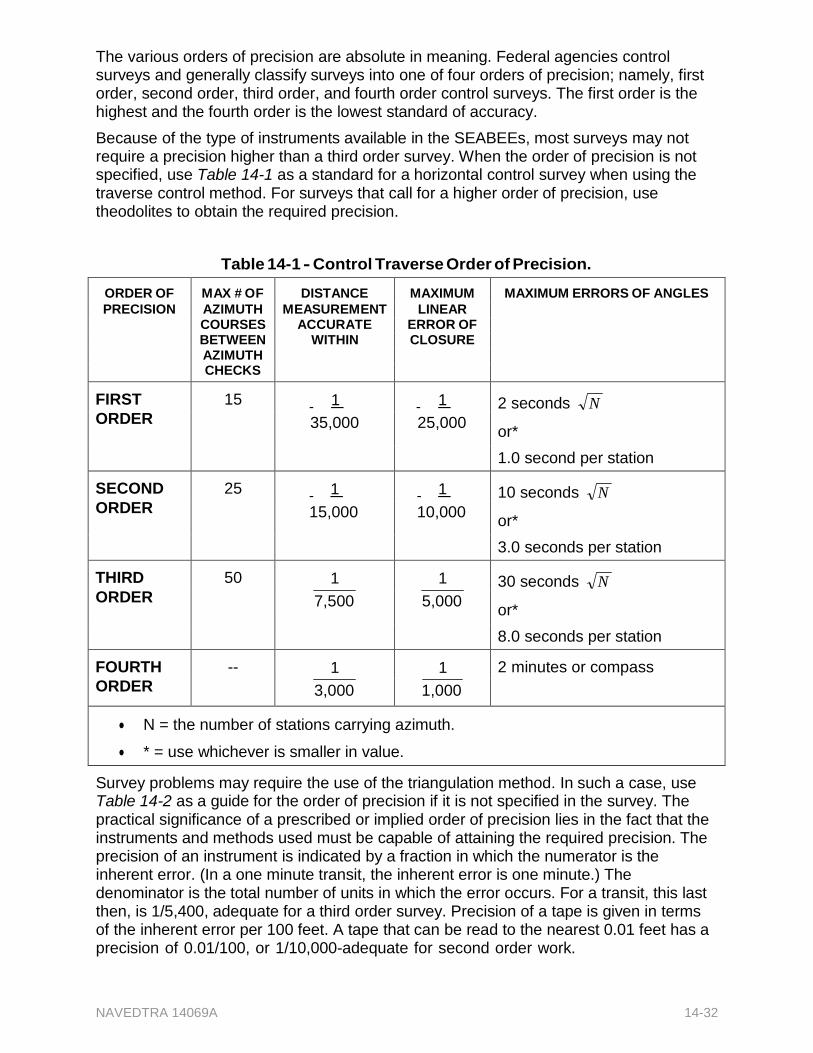
NAVEDTRA 14069A 14-32
The various orders of precision are absolute in meaning. Federal agencies control surveys and generally classify surveys into one of four orders of precision; namely, first order, second order, third order, and fourth order control surveys. The first order is the highest and the fourth order is the lowest standard of accuracy.
Because of the type of instruments available in the SEABEEs, most surveys may not require a precision higher than a third order survey. When the order of precision is not specified, use Table 14-1 as a standard for a horizontal control survey when using the traverse control method. For surveys that call for a higher order of precision, use theodolites to obtain the required precision.
Table 14-1 - Control Traverse Order of Precision.
ORDER OF MAX # OF DISTANCE MAXIMUM MAXIMUM ERRORS OF ANGLES PRECISION AZIMUTH MEASUREMENT LINEAR
COURSES ACCURATE ERROR OF BETWEEN WITHIN CLOSURE AZIMUTH CHECKS
FIRST 15 1 1 2 seconds N ORDER 35,000 25,000
or*
1.0 second per station
SECOND 25 1 1 10 seconds N ORDER 15,000 10,000
or*
3.0 seconds per station
THIRD 50 1 1 30 seconds N ORDER 7,500 5,000
or*
8.0 seconds per station
FOURTH -- 1 1 2 minutes or compass
ORDER 3,000 1,000
N = the number of stations carrying azimuth.
* = use whichever is smaller in value.
Survey problems may require the use of the triangulation method. In such a case, use Table 14-2 as a guide for the order of precision if it is not specified in the survey. The practical significance of a prescribed or implied order of precision lies in the fact that the instruments and methods used must be capable of attaining the required precision. The precision of an instrument is indicated by a fraction in which the numerator is the inherent error. (In a one minute transit, the inherent error is one minute.) The denominator is the total number of units in which the error occurs. For a transit, this last then, is 1/5,400, adequate for a third order survey. Precision of a tape is given in terms of the inherent error per 100 feet. A tape that can be read to the nearest 0.01 feet has a precision of 0.01/100, or 1/10,000-adequate for second order work.
NAVEDTRA 14069A 14-33
2.3.1 Attaining Precision with a Linear Error of Closure
For a closed traverse, attain a ratio of linear error of closure that corresponds to the order of precision prescribed or implied for the traverse. The ratio of linear error of closure is a fraction in which the numerator is the linear error of closure and the denominator is the total length of the traverse. To understand the concept of linear error of closure, study the closed traverse shown in Figure 14-26. Beginning at station C, this traverse runs N30°E300 feet, thence S30°E300 feet, thence S90°W 300 feet. The end of the closing traverse, BC, lies exactly on the point of beginning, C. This indicates that all angles were turned and all distances chained with perfect accuracy, resulting in perfect closure, or an error of closure of zero feet.
Table 14-2 - Triangulation Order of Precision.
PRECISION APPLICATION BASE LINE MEASUREMENT MAX., PROBABLY ERROR
TRIANGLE CLOSURE; MAX. AVERAGE ERROR
LENGTH CLOSURE: MAX. DISCREPANCY BETWEEN MEASURED AND COMPUTED LENGTH BASE LINE
FIRST ORDER Case I: For city 1 1.0 seconds 1
and scientific study survey
1,000,000 100,000
Case II: Basic 1 1.0 seconds 1
network of U.S. 1,000,000 50,000
Case III: All 1 1.0 seconds 1
other purposes 1,000,000 25,000
SECOND Case I: Area 1 1.5 seconds 1
ORDER networks and supplemental
1,000,000 20,000
cross arcs in
national net.
Case II: Costal 1 3.0 seconds 1
areas, inland waterways, and
500,000 10,000
engineering
surveys.
THIRD ORDER Topographic 1 5.0 seconds 1
mapping 250,000 5,000
NAVEDTRA 14069A 14-34
However, in reality, perfect accuracy in measurement seldom occurs. In actual practice, the closing traverse line, BC, (Figure 14-26), is likely to be some distance from the starting point, C. If this should happen, and the total accumulated linear distance measured along the traverse lines is 900.09 feet, the ratio of error of closure then is .09/900 or 1/10,000. This resulting ratio is equivalent to the precision prescribed for second order work.
2.3.2 Attaining Precision with a Maximum Angular Error
of Closure
The sum of interior angles of a closed traverse will theoretically equal the product of 180° (n - 2), n being the
Figure 14-26 - A closed traverse with a perfect
closure.
number of sides in the polygon described by the traverse. A prescribed maximum angular error of closure is stated in terms of the product of a given angular value times the square root of the number of interior angles in the traverse. Again, if we use the traverse shown in Figure 14-26 as an example, the prescribed maximum angular error of closure in minutes is 01 because the figure has three interior angles. The sum of the interior angles should be 180°. If the sum of the angles as actually measured and recorded is 179°57,, the angular error of closure is 03,. The maximum permissible error of closure is the product of 01, times the square root of 3, or about 1.73,. The prescribed maximum angular error of closure has therefore been exceeded.
2.3.3 Meeting Precision Specifications
There are several specifications that provide a general idea of the typical precision requirements for various types of transit tape surveys. When linear and angular errors of closure are specified, a closed traverse is involved.
Requirements for preliminary surveys and land surveys include the following:
o Transit angles to the nearest minute, measured once
o Sights on range poles plumbed by eye
o Tape leveled by eye, and standard tension estimated
o No temperature or sag corrections
o Slopes fewer than three percent disregarded
o Slopes over three percent measured by breaking chain or by chaining slope distance and applying calculated correction
o Maximum angular error of closure in minutes is 1.5
o Maximum ratio linear error of closure, 1/1000
o Pins or stakes set to nearest 0.1 foot
For most land surveys and highway location surveys, typical precision specifications may read as follows:
o Transit angles to nearest minute, measured once
o Sights on range poles, plumbed carefully
o Tape leveled by hand level, with standard tension by tensionometer or sag correction applied
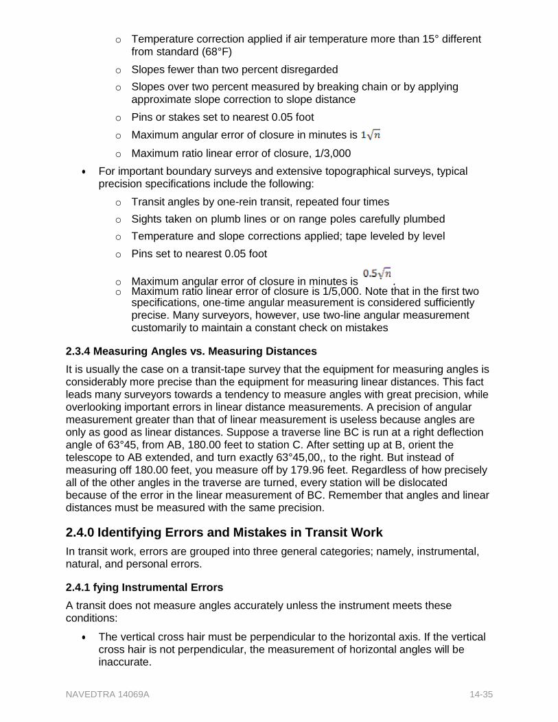
NAVEDTRA 14069A 14-35
o Temperature correction applied if air temperature more than 15° different from standard (68°F)
o Slopes fewer than two percent disregarded
o Slopes over two percent measured by breaking chain or by applying approximate slope correction to slope distance
o Pins or stakes set to nearest 0.05 foot
o Maximum angular error of closure in minutes is
o Maximum ratio linear error of closure, 1/3,000
For important boundary surveys and extensive topographical surveys, typical precision specifications include the following:
o Transit angles by one-rein transit, repeated four times
o Sights taken on plumb lines or on range poles carefully plumbed
o Temperature and slope corrections applied; tape leveled by level
o Pins set to nearest 0.05 foot
o Maximum angular error of closure in minutes is . o Maximum ratio linear error of closure is 1/5,000. Note that in the first two
specifications, one-time angular measurement is considered sufficiently precise. Many surveyors, however, use two-line angular measurement customarily to maintain a constant check on mistakes
2.3.4 Measuring Angles vs. Measuring Distances
It is usually the case on a transit-tape survey that the equipment for measuring angles is considerably more precise than the equipment for measuring linear distances. This fact leads many surveyors towards a tendency to measure angles with great precision, while overlooking important errors in linear distance measurements. A precision of angular measurement greater than that of linear measurement is useless because angles are only as good as linear distances. Suppose a traverse line BC is run at a right deflection angle of 63°45, from AB, 180.00 feet to station C. After setting up at B, orient the telescope to AB extended, and turn exactly 63°45,00,, to the right. But instead of measuring off 180.00 feet, you measure off by 179.96 feet. Regardless of how precisely all of the other angles in the traverse are turned, every station will be dislocated because of the error in the linear measurement of BC. Remember that angles and linear distances must be measured with the same precision.
2.4.0 Identifying Errors and Mistakes in Transit Work
In transit work, errors are grouped into three general categories; namely, instrumental, natural, and personal errors.
2.4.1 fying Instrumental Errors
A transit does not measure angles accurately unless the instrument meets these conditions:
The vertical cross hair must be perpendicular to the horizontal axis. If the vertical cross hair is not perpendicular, the measurement of horizontal angles will be inaccurate.
NAVEDTRA 14069A 14-36
The axis of each of the plate levels must be perpendicular to the vertical axis. If they are not, the instrument cannot be accurately leveled. If the instrument is not level, the measurement of both horizontal and vertical angles will be inaccurate.
The line of sight through the telescope must be perpendicular to the horizontal axis. If it is not, the line of sight through the telescope inverted will not be 1800 opposite the line of sight through the telescope erect.
The horizontal axis of the telescope must be perpendicular to the vertical axis. If it is not, the measurement of both horizontal and vertical angles will be inaccurate.
The axis of the telescope level must be parallel to the line of sight through the telescope. If it is not, the telescope cannot be accurately leveled. If the telescope cannot be accurately leveled, vertical angles cannot be accurately measured.
The point of intersection of the vertical and horizontal cross hairs must coincide with the true optical axis of the telescope. If it doesn't, measurement of both horizontal and vertical angles will be inaccurate.
Note
Any or all of the above conditions may be absent in an instrument that is defective or damaged, or one that needs adjustment or calibration.
2.4.2 fying Natural Errors
Common causes of natural errors in transit include:
The tripod is set in yielding soil. If the tripod settled evenly-that is, if the tip of each leg settled precisely the same amount-there would be little error in the results of measuring horizontal angles. Settlement is usually uneven, however, which results in the instrument not being level.
Refraction can be a problem; however, its effect is usually negligible in ordinary precision surveying.
Unequal expansion or contraction of instrument parts caused by excessively high or low temperature can also be a problem, but for ordinary precision surveying, the effect of this is also usually negligible.
High wind may cause plumbing errors when you are plumbing with a plumb bob and cord and may also cause reading errors because of instrument vibration.
2.4.3 fying Personal Errors
Personal errors are the combined results of carelessness and the eye's physical limitations in setting up, leveling the instrument, and making observations. Common causes of personal errors in transit work include:
Failure to plumb the vertical axis exactly over the station - Inaccuracy increases drastically as the sight distance decreases (Figure 14-27). As shown, an instrument that was supposed to be set up at A was actually set up at A,, 40 feet away from A. (For demonstration purposes the figure was exaggerated to magnify the error; in actual practice the eccentricity amounts only to a fraction of an inch. Remember that mathematically, one inch is the arc of one minute when the radius is 300 feet.). In the upper view, you can see that with B located 300 feet from A, the angular error caused by the displacement is about eight degrees. In the lower view, however, with B located only 100 feet from A, the angular error
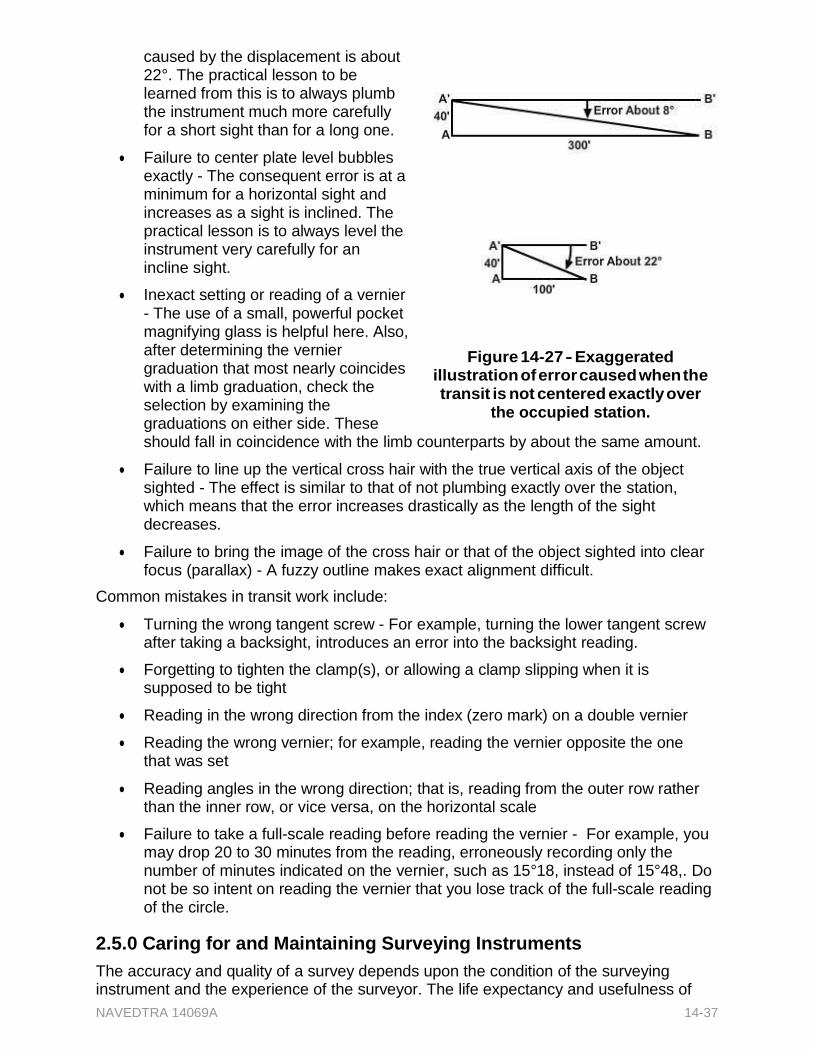
NAVEDTRA 14069A 14-37
caused by the displacement is about 22°. The practical lesson to be learned from this is to always plumb the instrument much more carefully for a short sight than for a long one.
Failure to center plate level bubbles exactly - The consequent error is at a minimum for a horizontal sight and increases as a sight is inclined. The practical lesson is to always level the instrument very carefully for an incline sight.
Inexact setting or reading of a vernier - The use of a small, powerful pocket magnifying glass is helpful here. Also, after determining the vernier graduation that most nearly coincides with a limb graduation, check the selection by examining the graduations on either side. These
Figure 14-27 - Exaggerated illustration of error caused when the transit is not centered exactly over
the occupied station.
should fall in coincidence with the limb counterparts by about the same amount.
Failure to line up the vertical cross hair with the true vertical axis of the object sighted - The effect is similar to that of not plumbing exactly over the station, which means that the error increases drastically as the length of the sight decreases.
Failure to bring the image of the cross hair or that of the object sighted into clear focus (parallax) - A fuzzy outline makes exact alignment difficult.
Common mistakes in transit work include:
Turning the wrong tangent screw - For example, turning the lower tangent screw after taking a backsight, introduces an error into the backsight reading.
Forgetting to tighten the clamp(s), or allowing a clamp slipping when it is supposed to be tight
Reading in the wrong direction from the index (zero mark) on a double vernier
Reading the wrong vernier; for example, reading the vernier opposite the one that was set
Reading angles in the wrong direction; that is, reading from the outer row rather than the inner row, or vice versa, on the horizontal scale
Failure to take a full-scale reading before reading the vernier - For example, you may drop 20 to 30 minutes from the reading, erroneously recording only the number of minutes indicated on the vernier, such as 15°18, instead of 15°48,. Do not be so intent on reading the vernier that you lose track of the full-scale reading of the circle.
2.5.0 Caring for and Maintaining Surveying Instruments
The accuracy and quality of a survey depends upon the condition of the surveying instrument and the experience of the surveyor. The life expectancy and usefulness of
NAVEDTRA 14069A 14-38
an instrument can be extended considerably by careful handling, stowing, and maintenance.
Every instrument is accompanied by an instruction manual that indicates not only the proper operation and components of the instrument but also procedures for its care and maintenance. Study this instruction manual thoroughly before attempting to use any instrument.
2.5.1 rying and Stowing
Every transit, theodolite, and level comes equipped with a carrying box or case. The instrument and its accessories can be stowed in the case in a manner that ensures a minimum of motion during transportation. Always stow instruments in their carrying cases when not in use.
2.5.2 and Lubricating
In general, all surveying instruments, equipment, and tools must be cleaned thoroughly immediately following use. For example, dust off the transit or theodolite and wipe it dry before placing it back in its case after each use. Remove all dust with a clean cloth. This applies particularly to the optical parts. Chamois leather is suitable for this purpose, but a clean handkerchief is better than a soiled chamois leather. Do not use liquid for cleaning - no water, petroleum products, or oil. If necessary, breathe on the lenses before polishing them. When the instrument becomes wet, remove its case and dry it thoroughly at room temperature as soon as is convenient. If you leave the instrument in the closed case, the air inside the hood will take up humidity by increasing temperature and will in time diffuse inside the instrument. While cooling off, the water will condense and form a coating or tarnish that may make any sighting with the telescope and reading of the circles difficult.
Remove any mud or dirt that may adhere to the tripod, range pole, level rod, and so forth, after each use. Clean each piece of equipment after each use to eliminate the chance of forgetting to later. This is important, especially when the surveying gear is made of a material susceptible to rust action or decay. When lubricating the instruments, use the recommended lubricant for each part in conjunction with the climatic condition in your area. For instance, graphite is the recommended lubricant for transit moving parts when the transit is to be used in sub-zero temperatures as opposed to the typical light film of oil (preferably watch oil) used in normal weather conditions. Apply the lubricant thinly to avoid making easy repositories for dust. Consult the manufacturer's manual or your senior EA whenever you are in doubt before doing anything to an instrument.
Test your Knowledge (Select the Correct Response)
4. When typing in a point to a station on a traverse, which of the following conditions should you carefully consider?
A. The selected tie station should not be easily disturbed. B. The tie station must be visible from the point to be tied in. C. Both A and B are correct. D. The angle between the tie lines should be no greater than 90°.
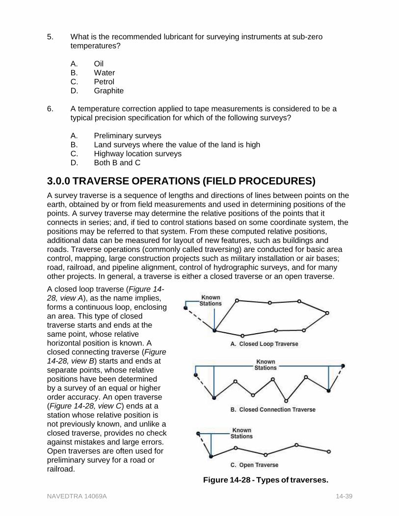
NAVEDTRA 14069A 14-39
5. What is the recommended lubricant for surveying instruments at sub-zero temperatures?
A. Oil B. Water C. Petrol D. Graphite
6. A temperature correction applied to tape measurements is considered to be a
typical precision specification for which of the following surveys?
A. Preliminary surveys B. Land surveys where the value of the land is high C. Highway location surveys D. Both B and C
3.0.0 TRAVERSE OPERATIONS (FIELD PROCEDURES)
A survey traverse is a sequence of lengths and directions of lines between points on the earth, obtained by or from field measurements and used in determining positions of the points. A survey traverse may determine the relative positions of the points that it connects in series; and, if tied to control stations based on some coordinate system, the positions may be referred to that system. From these computed relative positions, additional data can be measured for layout of new features, such as buildings and roads. Traverse operations (commonly called traversing) are conducted for basic area control, mapping, large construction projects such as military installation or air bases; road, railroad, and pipeline alignment, control of hydrographic surveys, and for many other projects. In general, a traverse is either a closed traverse or an open traverse.
A closed loop traverse (Figure 14- 28, view A), as the name implies, forms a continuous loop, enclosing an area. This type of closed traverse starts and ends at the same point, whose relative horizontal position is known. A closed connecting traverse (Figure 14-28, view B) starts and ends at separate points, whose relative positions have been determined by a survey of an equal or higher order accuracy. An open traverse (Figure 14-28, view C) ends at a station whose relative position is not previously known, and unlike a closed traverse, provides no check against mistakes and large errors. Open traverses are often used for preliminary survey for a road or railroad.
Figure 14-28 - Types of traverses.
NAVEDTRA 14069A 14-40
The order of accuracy for any traverse is determined by the equipment and methods used in the traverse measurements, by the accuracy attained, and by the accuracy of the starting and terminating stations. Hence, the order of accuracy is specified before the measurements are started. For engineering and mapping projects, the distance measurement accuracy for both electronic and taped traverses for first, second, and third order are 1/35,000, 1/15,000, and 1/7,500, respectively.
For military use such as field artillery, lower order accuracies of fourth, fifth, and sixth are 1/3,000, 1/1,000, and 1/500, respectively. The order referred to as lower order is applied to all traverses of less than third order. To accomplish a successful operation, the traverse party chief must ensure that initial preparations and careful planning are done before the actual traversing begins.
3.1.0 Organizing the Party
A traverse party may vary in size anywhere from two to twelve personnel, all under the supervision of a traverse party chief. A traverse party usually consists of a distance measuring crew, an angle crew, sometimes a level crew, and other support personnel. This breakdown of personnel is ideal, but on many occasions, the same personnel will have to perform a variety of tasks or functions. Therefore, each party member is trained to assume various duties and functions in several phases of the work survey.
3.2.0 Conducting a Reconnaissance
Whenever possible, make a reconnaissance to determine the starting point, the route to be followed, the points to be controlled, and the closing station. When selecting the starting and closing points, select an existing control station that was determined by a survey whose order of accuracy was equal to or greater than the traverse to be run. When running a traverse in which the direction of the traverse lines are not fixed before the start, select a route that offers minimum clearing of traverse lines. Use the best available maps and aerial photographs during the office and field reconnaissance. By selecting a route properly, you can lay out the traverse to pass relatively close to points that have to be located or staked out.
On other surveys, such as road center line layout, predetermine the directions of the traverse lines, and clear all obstructions, including large trees, from the line. Often the assistance of the equipment and construction crews is needed at this point. For the lower order surveys and where you use taping, select the exact route and station locations as the traverse progresses. Always select these stations so that at any one station, both the rear and forward stations are visible, and only a minimum number of instrument setups is kept, reducing the possibility of instrument error and the amount of computing required.
Furthermore, the Electronic Distance-Measuring (EDM) devices have made traverse reconnaissance even more important. Consider the possibility of using an EDM after the general alignment in direction and the planned positioning of stations. A tower or platform installed to clear surface obstruction will permit comparatively long optical sights and distance measurements, hence avoiding the necessity of taping it in short increments.
3.3.0 Placing Station Marks
Some station marks are permanent markers, and some are temporary markers, depending upon the purpose of the traverse. A traverse station that will be reused over a period of several years is usually marked in a permanent manner. Permanent traverse
NAVEDTRA 14069A 14-41
station markers take various forms, including iron pipe filled with concrete, a crosscut in concrete or rock, or a hole drilled in concrete or rock and filled with lead, with a tack to mark the exact reference point. Temporary markers are used on traverse stations that may never be reused, or perhaps will be reused only a few times within a period of one or two months. Temporary traverse station markers are usually two-inch by two-inch wooden hubs, 12 inches or more in length. They are driven flush with the ground and have a tack or small nail on top to mark the exact point of reference for angular and linear measurements. To assist in recovering the hub, a one-inch by two-inch wooden guard stake, 16 inches or more in length is driven at an angle so that its top is about one foot over the hub. Keel (lumber crayon) or a large marking pen is used to mark letters and/or numbers on the guard stake to identify the hub. The marked face of the guard stake is toward the hub. Since many of the hubs marking the location of road center lines, landing strips, and other projects will require replacement during construction, reference marks are placed several hundred feet or meters away from the station they reference. Reference marks, usually similar in construction to that of the station hub, are used to reestablish a station if its marker has been disturbed or destroyed.
3.4.0 Tying In to Existing Control
As previously discussed, the starting point of a closed traverse must be a known position or control point; and, for a closed loop traverse, this point is both the starting and closing point. Closed connecting traverses start at one control point and tie into another control point.
A traverse starting point should be an existing station with another station visible for orienting the new traverse. The adjacent station must be intervisible with the starting point to make the tie easy. If you do not find the adjacent station easily, observe an astronomic azimuth to orient the starting line, and then continue the traverse. Any existing control near the traverse line should be tied into the new work.
3.5.1 Performing Linear Measurements
As traversing progresses, conduct linear measurements to determine the distance between stations or points. Generally, the required traverse accuracy will determine the type of equipment and the method of measuring the distance. For the lower orders, a single taped distance is sufficient. However, as the order of accuracy gets higher, DOUBLE TAPING (once each way) is required. Compare ordinary steel tapes to an Invar or Lovar tape at specified intervals. For the highest accuracy, use electronic distance-measuring devices (EDM) to measure linear distances. Linear measurements may also be made by indirect methods, using an angle measuring instrument like the transit or theodolite with stadia. When determining the distances by stadia readings, read the vertical angles and use them to convert slope distances to horizontal distances.
If double taping or chaining is required, follow these procedures:
1. Follow a direct line between stations, using a guide, such as a transit and a range pole, for alignment. Start measuring from the occupied station, keeping the front end of the tape aligned with the forward station.
2. Start back from the forward station, using the same alignment but not the same taping points. The second measurement is independent of the first.
NAVEDTRA 14069A 14-42
3. Compare the two distances, and if the measurement is within accuracy requirements, accept the distance. If the two measurements disagree by more than the allowable amount, retape the distance.
4. Proceed to the next line measurement, and continue double taping until the tie-in control point is reached.
3.6.0 Performing Angular Measurement
Horizontal angles formed by the lines of each traverse station determine the relative directions of the traverse lines. These angles are measured using a transit or a theodolite, and can also be determined graphically with a plane table and alidade. In a traverse, three traverse stations are significant: the rear station, the occupied station, and the forward station (Figure 14-29).
Figure 14-29 - Traverse stations and angles.
The rear station is the station from which the crew performing the traverse has just moved, or is a point, the azimuth to which is known. The occupied station is the station at which the crew is now located and over which the surveying instrument is set. The forward station is the next station in succession and constitutes the immediate destination of the crew. The stations are numbered consecutively starting at one and continuing throughout the traverse. In addition to the number of the station, an abbreviation indicating the type of traverse is often times included; for example, ET for electronic traverse or TT for theodolite- or transit-tape traverse. Always measure horizontal angles at the occupied station by pointing the instrument toward the rear station and turning the angle clockwise to the forward station for the direct angle and clockwise from the forward to the rear station for the explement (Figure 14-30). If you use a deflection angle, plunge the instrument telescope after sighting the rear station, and read the angle left or right of the forward station.
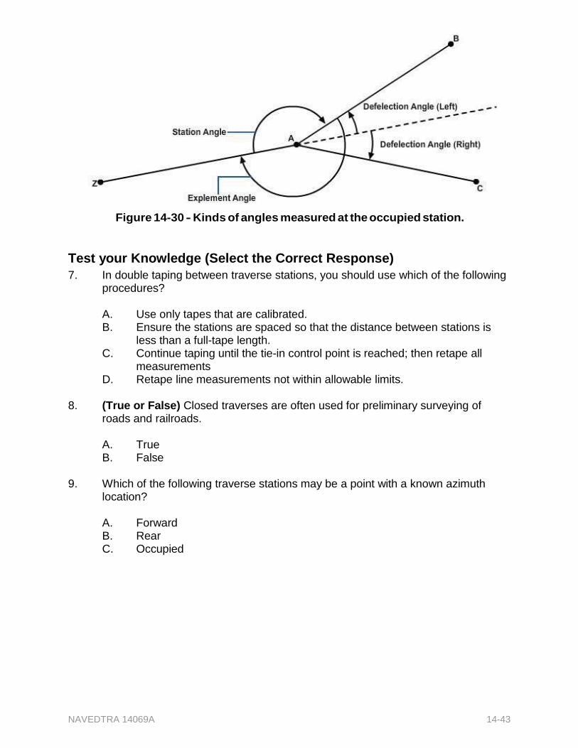
NAVEDTRA 14069A 14-43
Figure 14-30 - Kinds of angles measured at the occupied station.
Test your Knowledge (Select the Correct Response)
7. In double taping between traverse stations, you should use which of the following procedures?
A. Use only tapes that are calibrated. B. Ensure the stations are spaced so that the distance between stations is
less than a full-tape length. C. Continue taping until the tie-in control point is reached; then retape all
measurements D. Retape line measurements not within allowable limits.
8. (True or False) Closed traverses are often used for preliminary surveying of
roads and railroads.
A. True B. False
9. Which of the following traverse stations may be a point with a known azimuth
location?
A. Forward B. Rear C. Occupied

NAVEDTRA 14069A 14-44
Summary
This chapter presented you with information relating to the determination of distance and direction. Specifically, you were introduced to conversion methods for bearings, deflections, and interior and exterior angles, through arithmetic and the use of a compass. After being familiarized with distance and direction, you were presented with the procedures used to conduct transit tape surveys, which includes such tasks as meeting the required order of precision, identifying errors and mistakes, as well as caring for equipment and instruments. Finally, the steps necessary to conduct accurate traverse operations was covered, including organizing the survey party, conducting reconnaissance, and performing the surveying tasks.
NAVEDTRA 14069A 14-45
Review Questions (Select the Correct Response) 1. A traverse that has been established and is used to locate detail points and
objects are located is a .
A. traverse B. control line C. control traverse D. horizontal control
2. (True or False) In true geographical direction, the reference line is the meridian
passing through the point where the observer is located, and the direction of a line passing through that point is described in terms of the horizontal angle between that line and the meridian.
A. True B. False
3. The bearing of line AB in the traverse is S2726'W and the bearing of the line BC
is N10°17'W. What is the deflection angle between AB and BC in the figure?
A. 37°43' B. 79°42' C. 141°60' D. 142°17'
4. The directions of traverse lines AB and BC are indicated by deflection angles.
Determine the bearing of BC by using the figure.
A. N1°E B. N20°E C. N23°E D. N43°E
5. How many degrees are there in the exterior angle ABC as shown in the figure?
A. 205° B. 210° C. 220° D. 235°
6. How many degrees are here in the interior angle ABC as shown in the figure?
A. 120° B. 130° C. 140° D. 150°
NAVEDTRA 14069A 14-46
7. To convert a bearing in the SE quadrant to the equivalent azimuth, you must use which of the following calculations?
A. Add 90 degrees to the bearing. B. Add 180 to the bearing. C. Subtract the bearing from 180°. D. Subtract the bearing from 360°.
8. Assume that a measured forward bearing on a compass-tape survey was
N15°35'W and the back bearing on the same line was S15°15'E. The difference was probably caused by which of the following conditions?
A. Declination B. Local attraction C. An error in reading the compass D. A defect in the compass mechanism
9. The magnetic declination at a given point on the surface of the earth is the
horizontal angle that the magnetic meridian makes with what line?
A. The agonic line B. The true meridian C. The isogonic line D. The assumed meridian
10. What is the appropriate compass bearing of the object in the figure?
A. Due north B. S70°W C. S30°W D. S30°E
11. What is the approximate magnetic bearing of the object if the local attraction is
20°E?
A. Due west B. S50°W C. Due south D. N20°W
12. What method should you use to correct or convert a compass azimuth reading to
a true azimuth reading when both local attraction and local declination are easterly?
A. Subtract the attraction and declination from the compass reading. B. Add the attraction and declination to the compass reading. C. Add the attraction to the compass reading, then subtract the declination
from the sum. D. Add the declination to the compass reading, then subtract the attraction
from the sum.
NAVEDTRA 14069A 14-47
13. When making a closed traverse compass-tape survey, why should you first read and record the back bearing of a traverse line from the first setup point?
A. To offset local attraction B. To get rid of declination C. To check the accuracy of your compass D. To verify the last bearing you will take
14. What is the sum of the interior angles in a closed traverse consisting of size
traverse lines?
A. 360° B. 540° C. 720° D. 1,080°
15. If a compass is in error when you are taking bearings at several different places
and each error varies from the preceding one, the errors are probably due to which of the following factors?
A. A shifted movable circle B. A bent frame C. A bent pivot D. A bent needle
16. The only compass available for taking bearings has an instrument error. What
forward bearing should you use when the compass needle indicates a forward bearing of N22°W and a back bearing of S24°E?
A. S2°E B. S46°W C. N46°E D. N23°W
17. You are using a compass that has an instrument error and is graduated for
azimuths. What forward azimuth should you record when the compass needle indicates a forward azimuth of 37° and a back azimuth of 219°?
A. 37° B. 38° C. 91° D. 128°
18. Which of the following defects is most likely to cause a compass to read
incorrectly at both ends of its needle?
A. A bent pivot B. A warped compass card C. A bent needle D. A blunt pivot point
NAVEDTRA 14069A 14-48
19. A compass needle that is weak magnetically should be strengthened by which of the following methods?
A. Placing the magnet in an inductive field B. Drawing the needle over a magnet C. Placing the magnet in a shielded box D. Heating the needle with a lighted match
20. A compass needle acts sluggishly although it has retained its full magnetism.
Which of the following methods should be used to make the needle act as it should?
A. Sharpen its points B. Sharpen the point on the pivot C. Reshape it with a special tool D. Demagnetize it
21. In setting up and leveling a transit, you have followed all of the correct
procedures. You discover, however, that the plumb bob is still not quite directly over the station point. Which of the following actions should be taken next?
A. Loosen two adjacent leveling screws to free the shifting plate and shift the
transit head laterally. B. Replace the plumb bob. C. Adjust the tripod legs. D. Re-level the instrument.
22. Before taking up the transit, which of the following actions should you take
concerning the telescope and the vertical motion clamp?
A. Bring the telescope perpendicular to the vertical axis and firmly tighten the clamp.
B. Point the telescope vertically upward and firmly tighten the clamp. C. Point the telescope vertically upward and loosen the clamp. D. Point the telescope vertically upward and lightly tighten the clamp.
23. In which of the following ways are the horizontal limbs of transits numbered?
A. 0°-360° clockwise B. 0°-360° clockwise, also 0°-90° by quadrants C. 0°-360° clockwise, also 360°-0° counterclockwise D. Each of the above
24. When you are turning a 40° horizontal angle by transit, what part will normally
point to the number of degrees turned?
A. Zero on the A-vernier B. Zero on the B-vernier C. 0°-360° graduation on the horizontal limb D. 40°-320° graduation on the horizontal limb
NAVEDTRA 14069A 14-49
25. Releasing the upper motion of a transit enables you to take which of the following actions?
A. Hold the telescope in place. B. Rotate and train the telescope. C. Hold the horizontal limb in place. D. Rotate and align the horizontal limb.
26. Which of the following steps should you normally take when turning a 20°
horizontal angle from a reference line with a transit?
A. Clamp the lower motion to hold the telescope in place after training it on the reference line.
B. Release the lower motion to rotate the telescope 20°. C. Align the 0°-360° graduation on the horizontal limb with the zero on the A-
vernier. D. Align the 0°-360° graduation on the horizontal limb with the zero on the B-
vernier. 27. To fix the exact position of the horizontal limb with respect to the A-vernier, what
transit screw, if any, should you use?
A. Telescope clamp screw B. Upper motion tangent screw C. Lower motion tangent screw D. None
28. The closing-the-horizon method of checking the accuracy of angular
measurements is based on the geometric fact that the sum of the:
A. Angles in a triangle are 180°. B. Angles around a point are 360°. C. Acute angles in a right triangle are 90°. D. Interior angles of a five-course traverse are 540°.
29. A vertical angle was recorded at +36°. This angle is a measurement of what
type?
A. Inclination B. Declination C. Depression D. Elevation
30. You are measuring a 30° angle with a one-minute transit. To improve the
precision of this measurement, you turn the angle a total of four times. If the plate reading after the fourth measurement is 119°59', what is the size of the angle turned?
A. 29°45'45" B. 29°59'45" C. 30°00'15" D. 30°45'15"
NAVEDTRA 14069A 14-50
31. You have measured an angle using the repetition procedure. If the original measurement was 37°22' and your sixth and last repeat was 224°12'42", what is the mean angle?
A. 37°5'7" B. 37°22'7" C. 37°10'20" D. 38°00'57"
32. Which of the following procedures is a method for extending a straight line?
A. Repeating angles B. Averaging sets of backsight points C. Double centering
33. What step in the double-centering procedure is taken just before the instrument
is rotated through 180° in the horizontal plane?
A. Plunging the telescope B. Taking the first foresight C. Taking the backsight D. Taking the second foresight
34. When double centering resets in two different extension points, what procedure
should you use?
A. Extend your line through the first point B. Extend your line through the second point C. Extend your line through a point midway between the two extension points D. Ignore both points and start over again
35. After recording the deflection angle at D as shown in the figure, what is the next
step?
A. Take a backsight at A and measure angle ABC. B. Move the instrument to D and measure the deflection angle at D. C. Move the instrument to C and measure the deflection angle at C. D. Move the instrument to A and measure angle BAC.
36. If you use the angle offset method of bypassing an obstacle, what is the size of
the deflection angle at C as shown in the figure?
A. 30° B. 45° C. 60° D. 75°
NAVEDTRA 14069A 14-51
37. Which of the following distances is equal to CD as shown in the figure?
A. AB B. BD C. DE D. BC
38. What is the deflection angle at point D as shown in the figure?
A. 30°L B. 30°R C. 60°L D. 60°R
39. The angle offset and the perpendicular offset methods are useful in establishing
a survey line under which of the following conditions?
A. When the length of the survey line cannot be determined by chaining B. When the slope becomes great enough to require breaking chain C. When the LOS on the chosen survey line is obstructed D. When the backsight distance is much less than the foresight distance
40. The "balancing in" process should be used to locate an intermediate point
between two control points on a survey line under which of the following conditions?
A. When the distances from the intermediate point to the control points are approximately equal
B. When neither control point is visible from the other, and the other methods of bypassing an obstacle cannot be used
C. When the intermediate point is much closer to one of the control points than it is to the other
D. When the instrument adjustment has a known error. 41. If deflection angles a and � as shown in the figure are four and six minutes,
respectively, and distance a is four feet, how far should you set up the instrument from B' so that it is exactly in line with points A and C?
A. 1.0 foot B. 1.4 feet C. 1.6 feet D. 2.4 feet
NAVEDTRA 14069A 14-52
42. For which of the following situations should the random line method be used?
A. To run a line between nonintervisible end points from an intermediate point from which both end points are visible
B. To run a line between nonintervisible end points when there is no intermediate point from which both end points are visible
C. To establish intermediate stations between nonintervisible end points D. Both B and C
43. What typing-in method should you use when locating the configuration of an
irregular shoreline from a traverse line?
A. Swing offsets B. Random lines C. Range ties D. Perpendicular offsets
44. What meaning is generally given to the term "settling a point"?
A. Establishing a point at a designated location B. Relocating control points that have been destroyed C. Locating reference lines for a displaced station D. Setting the instrument upon a designated point
45. You can tie-in a point or set a point to two stations on a traverse by taking which
of the following measurements?
A. Its angle and distance from one station B. Two of its angles, one from each station C. Its distance from one station and its angle from the other station D. Each of the above
46. Surveyors use straddlers for what purpose?
A. To relocate control points that have been destroyed B. To tie in a new traverse with reference to its angle to an old survey line C. To tie in a point with reference to its angle from two stations D. To locate the reference lines for a displaced station
47. You must set a marker at a certain point from traverse station 3 + 00 and 4 + 25.
The angle from the traverse line to station 3 + 00 and the distance between the point and station 4 + 25 are given. How should you proceed to set the point?
A. Solve for the other angle from the base line, and the distance of the point
from the other station; then, set the point by using transit and tape. Check the distance and other angle from the base line.
B. Solve for the angle from the base line to the distance line and set the point by the use of transit and tape. Then check by measuring the base line.
C. Lay out the lines to the point with tape and straddlers, and then check the lines with a transit.
D. Lay out the lines to the point with tape and straddlers and check by re- measuring one leg of the triangle.
NAVEDTRA 14069A 14-53
48. A closed traverse was to be 15,000 feet in length. The last course was to be 3,000 feet in length. After you turn the last deflection angle and progress 3,000 feet on the last course, you find that you are three feet from the starting point of the traverse. What is the order of precision?
A. First B. Second C. Third D. Fourth
49. If precision of 1/20,000 is required, what is the maximum allowable error of
closure for a traverse of 10,560 feet?
A. 0.437 feet B. 0.528 feet C. 0.759 feet D. 1.255 feet
50. Which of the following errors in a transit affects both horizontal and vertical angle
measurements?
A. The LOS through the telescope does not coincide with the true optical axis of the telescope.
B. The horizontal axis of the telescope is not perpendicular to the vertical axis.
C. The axis of each of the plate levels is not perpendicular to the vertical axis of the telescope.
D. A, B, and C 51. Which of the following personal errors results in a larger error for inclined sights
than for horizontal sights?
A. Failure to focus correctly B. Failure to center the plate C. Failure to plumb the transit exactly D. Failure to line up the vertical cross hair with the true vertical axis of the
sighted object 52. Which of the following situations is considered a mistake in transit work?
A. Failure to record the direction in which an angle was turned B. Turning the deflection angle in the wrong direction C. Reading the wrong vernier D. A, B, and C
NAVEDTRA 14069A 14-54
53. The carrying case for a transit or a theodolite is specifically designed for which of the following conditions?
A. To protect the instrument from extreme temperatures B. To serve as a part of the instrument when it is set up for use in the field C. To prevent excess motion when the instrument is being carried D. All of the above
54. Which of the following actions should you take after an instrument has been
exposed to rain and has been wiped down with a clean cloth or chamois leather?
A. Dry it in a heated room. B. Stow it in its case right away. C. Dry it thoroughly at ordinary room temperature.
55. Which of the following statements describes the characteristics of an open
traverse as compared to a closed connecting traverse?
A. An open traverse has only one previously determined end point, but a closed connecting traverse has two
B. Both types of traverses may not be used for preliminary surveys C. An open traverse is open at both ends, but a a closed connecting traverse
forms a loop so that the ends are closed D. A closed traverse provides fewer checks against error than an open
traverse
NAVEDTRA 14069A 14-55
Trade Terms Introduced in this Chapter
Bearings The direction of a line within a quadrant, with respect to the meridian. Bearings are measured clockwise or counterclockwise from north to south, depending on the quadrant.
Control Line Any line from which points and objects are located Control Traverse A traverse that has been established and is used to
locate detail points and objects.
Deflection Angle A horizontal angle measured from the prolongation of the preceding line, clockwise or counterclockwise as necessary, to the following line.
Horizontal Control Control that determines horizontal positions only, with respect to parallels and meridians or to other lines of reference.
LOS Line of Sight Meridian A north-south line from which longitudes (or departures)
and azimuths are reckoned.
Minus Vertical Angle/Angle of Depression
A negative altitude.
Nadir The point directly beneath a given position or observer and diametrically opposite to the zenith.
Parallax The apparent displacement or the difference in apparent direction of an object as seen from two different points not on a straight line with the object. In testing the focus of a telescope, the head of the observer must move from side to side or up and down while sighting through the eyepiece. Any apparent movement of the cross hairs in relation to the object image means that parallax is present. Parallax can be practically eliminated by careful focusing.
Parallel Lines Two or more meridians on the same plane.
Plus Vertical Angle/Angle of Elevation
A positive altitude.
Traverse Any line surveyed across a parcel, or a series of such lines connecting a number of points, often used as a base for triangulation.

NAVEDTRA 14069A 14-56
Zenith An imaginary point overhead where the extension of the plumb line will intersect an assumed sphere on which the stars appear projected.
NAVEDTRA 14069A 14-57
Additional Resources and References
This chapter is intended to present thorough resources for task training. The following reference works are suggested for further study. This is optional material for continued education rather than for task training.
Brinker, R. C. and P. R. Wolf, Elementary Surveying, 6th ed., Harper & Row, Publishers, New York, 1977.
Davis, R. E., F. S. Foote, J. M. Anderson, and E. M. Mikhail, Surveying, Theory and Practice, 6th ed, McGraw-Hill Book Co., New York, 1981.
Legault, A. R. H. M. McMaster, and R. R. Marlette, Surveying, an Introduction to Engineering Measurement, Prentice-Hall, Inc., Englewood Cliffs, N.J., 1956.
U.S. Department of Defense, Elements of Surveying, TM 5-232, Headquarters, Department of the Army, Washington, D.C., 1971.

NAVEDTRA 14069A 14-58
CSFE Nonresident Training Course - User Update
CSFE makes every effort to keep their manuals up-to-date and free of technical errors. We appreciate your help in this process. If you have an idea for improving this manual, or if you find an error, a typographical mistake, or an inaccuracy in CSFE manuals, please write or email us, using this form or a photocopy. Be sure to include the exact chapter number, topic, detailed description, and correction, if applicable. Your input will be brought to the attention of the Technical Review Committee. Thank you for your assistance.
Write: CSFE N7A 3502 Goodspeed St. Port Hueneme, CA 93130
FAX: 805/982-5508
E- mail: [email protected]
Rate_ Course Name
Revision Date Chapter Number Page Number(s)
Description
(Optional) Correction
(Optional) Your Name and Address
NAVEDTRA 14069A 15-1
Chapter 15
Direct Leveling and Basic Engineering Surveys
Topics
1.0.0 Basic Terms Used in Leveling Operations
2.0.0 Level Party Organization, Equipment, and Field Procedures
3.0.0 Methods of Leveling
4.0.0 Precision in Leveling; Mistakes and Errors in Leveling
5.0.0 Basic Engineering Surveys and Construction Site Safety
To hear audio, click on the box.
Overview
The leveling operation is used to determine the elevations of points or the differences in elevation between points on the earth's surface. The leveling operation is important for deriving the data required for various engineering designs, mapping, and construction projects. Data from a finished level survey is used to design roads, highways, and airfields. The data is also used to develop maps showing the general configuration of the ground. Information obtained from leveling operations is used to calculate the volume of earthwork required to complete a construction project.
This chapter addresses the basic principles of direct leveling and the methods used, as well as the duties and responsibilities of the leveling crew. Differential leveling field procedures, precision leveling, and the proper handling of leveling instruments and equipment are also discussed. In addition, this chapter includes a general description of basic engineering surveys and various construction site safety hazards commonly encountered by a survey party.
Objectives
When you have completed this chapter, you will be able to do the following:
1. Identify the basic terms used in leveling operations.
2. Describe level party organization, equipment, and field procedures.
3. Describe the different methods for conducting leveling operations.
4. Identify common mistakes and errors in leveling operations.
5. Describe the different types of basic engineering surveys and construction site safety.
Prerequisites
None
NAVEDTRA 14069A 15-2
This course map shows all of the chapters in Equipment Operator Basic. The suggested training order begins at the bottom and proceeds up. Skill levels increase as you advance on the course map.
Topographic Surveying and Mapping
E
Indirect Leveling/Level and Traverse Computations
N Care and Adjustment of Survey Equipment
G Materials Testing: Soil and Concrete
I
Direct Leveling and Basic Engineering Surveys N
Horizontal Control E
Direct Linear Measurements and Field Survey Safety E
Surveying: Elements and Equipment R
I Construction Drawings
N
Electrical: Systems and Plans G
Mechanical: Systems and Plans
Concrete and Masonry AID
Wood and Light Frame Structures
B
Drafting: Projections and Sketching A
Drafting: Geometric Construction S
Drafting: Fundamentals and technique I
Drafting: Equipment C
Mathematics and Units of Measurement
Engineering Aid Rating
Features of this Manual
This manual has several features which make it easy to use online.
Figure and table numbers in the text are italicized. The figure or table is either next to or below the text that refers to it.
The first time a glossary term appears in the text, it is bold and italicized. When your cursor crosses over that word or phrase, a popup box displays with the appropriate definition.
Audio and video clips are included in the text, with italicized instructions telling you where to click to activate it.
Review questions that apply to a section are listed under the Test Your Knowledge banner at the end of the section. Select the answer you choose. If

NAVEDTRA 14069A 15-3
the answer is correct, you will be taken to the next section heading. If the answer is incorrect, you will be taken to the area in the chapter where the information is for review. When you have completed your review, select anywhere in that area to return to the review question. Try to answer the question again.
Review questions are included at the end of this chapter. Select the answer you choose. If the answer is correct, you will be taken to the next question. If the answer is incorrect, you will be taken to the area in the chapter where the information is for review. When you have completed your review, select anywhere in that area to return to the review question. Try to answer the question again.
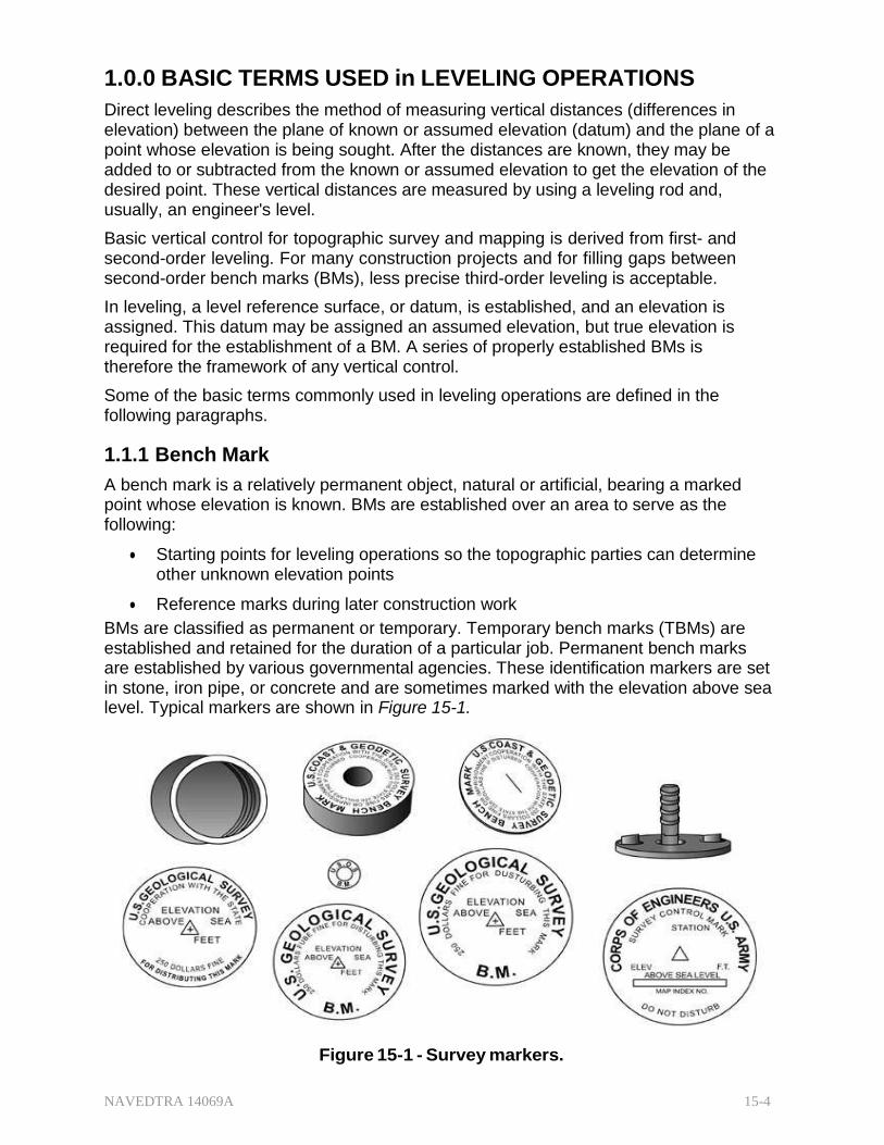
NAVEDTRA 14069A 15-4
1.0.0 BASIC TERMS USED in LEVELING OPERATIONS
Direct leveling describes the method of measuring vertical distances (differences in elevation) between the plane of known or assumed elevation (datum) and the plane of a point whose elevation is being sought. After the distances are known, they may be added to or subtracted from the known or assumed elevation to get the elevation of the desired point. These vertical distances are measured by using a leveling rod and, usually, an engineer's level.
Basic vertical control for topographic survey and mapping is derived from first- and second-order leveling. For many construction projects and for filling gaps between second-order bench marks (BMs), less precise third-order leveling is acceptable.
In leveling, a level reference surface, or datum, is established, and an elevation is assigned. This datum may be assigned an assumed elevation, but true elevation is required for the establishment of a BM. A series of properly established BMs is therefore the framework of any vertical control.
Some of the basic terms commonly used in leveling operations are defined in the following paragraphs.
1.1.1 Bench Mark
A bench mark is a relatively permanent object, natural or artificial, bearing a marked point whose elevation is known. BMs are established over an area to serve as the following:
Starting points for leveling operations so the topographic parties can determine other unknown elevation points
Reference marks during later construction work
BMs are classified as permanent or temporary. Temporary bench marks (TBMs) are established and retained for the duration of a particular job. Permanent bench marks are established by various governmental agencies. These identification markers are set in stone, iron pipe, or concrete and are sometimes marked with the elevation above sea level. Typical markers are shown in Figure 15-1.
Figure 15-1 - Survey markers.

NAVEDTRA 14069A 15-5
When an elevation is not marked, the information can be found by contacting the governmental agency responsible for the original BM.
BMs may be constructed in several ways. Figure 15-2 shows brass shaft stocks in the tops of permanent horizontal control points (monuments). Monuments of this type may also be used as vertical control BMs. Original BMs may be constructed in the same manner. When a regular BM disk is not available, brass, not steel, 50-caliber empty shell casings may be used.
Figure 15-2 - Horizontal control markers used as BMs.
For short lines and a level circuit of a limited area, any substantial object may be used for vertical control BMs. A remark in your field notes should detail the proper identification of the BMs used.
Figure 15-3 shows a mark commonly used on tops of concrete walls and foundations. Lines are chiseled with a cold chisel or small star drill and then marked with paint or keel (lumber crayon). The chiseled figures should be about the same size as the base area of the rod, preferably, placed on some high spot on the surface of the concrete structure.
Figure 15-3 - Benchmarks located on concrete structure.
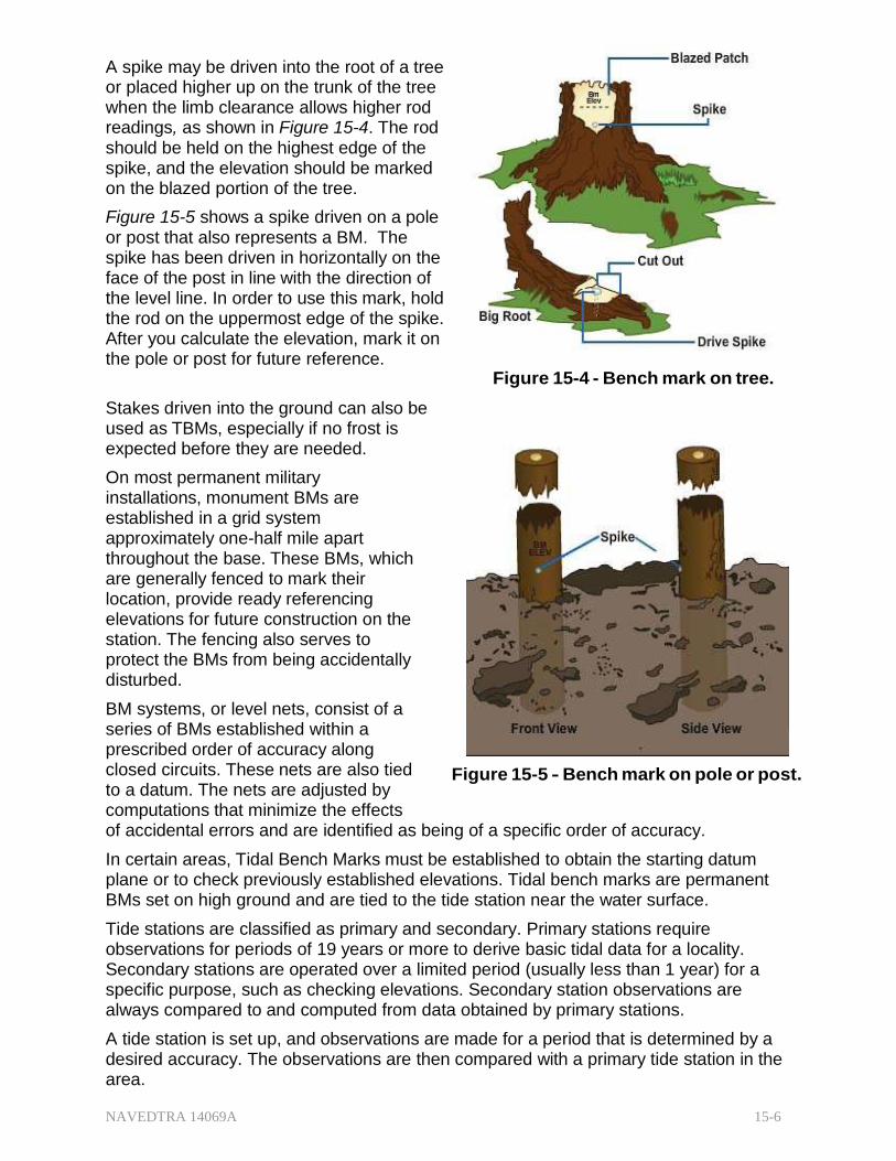
NAVEDTRA 14069A 15-6
A spike may be driven into the root of a tree or placed higher up on the trunk of the tree when the limb clearance allows higher rod readings, as shown in Figure 15-4. The rod should be held on the highest edge of the spike, and the elevation should be marked on the blazed portion of the tree.
Figure 15-5 shows a spike driven on a pole or post that also represents a BM. The spike has been driven in horizontally on the face of the post in line with the direction of the level line. In order to use this mark, hold the rod on the uppermost edge of the spike. After you calculate the elevation, mark it on the pole or post for future reference.
Stakes driven into the ground can also be used as TBMs, especially if no frost is expected before they are needed.
On most permanent military installations, monument BMs are established in a grid system approximately one-half mile apart throughout the base. These BMs, which are generally fenced to mark their location, provide ready referencing elevations for future construction on the station. The fencing also serves to protect the BMs from being accidentally disturbed.
BM systems, or level nets, consist of a series of BMs established within a prescribed order of accuracy along closed circuits. These nets are also tied to a datum. The nets are adjusted by computations that minimize the effects
Figure 15-4 - Bench mark on tree.
Figure 15-5 - Bench mark on pole or post.
of accidental errors and are identified as being of a specific order of accuracy.
In certain areas, Tidal Bench Marks must be established to obtain the starting datum plane or to check previously established elevations. Tidal bench marks are permanent BMs set on high ground and are tied to the tide station near the water surface.
Tide stations are classified as primary and secondary. Primary stations require observations for periods of 19 years or more to derive basic tidal data for a locality. Secondary stations are operated over a limited period (usually less than 1 year) for a specific purpose, such as checking elevations. Secondary station observations are always compared to and computed from data obtained by primary stations.
A tide station is set up, and observations are made for a period that is determined by a desired accuracy. The observations are then compared with a primary tide station in the area.

NAVEDTRA 14069A 15-7
A closed loop using spirit levels is run from the tide station over the tidal BMs and is tied back to the tide station. The accuracy of this level line must be the same as or higher than the accuracy required for the BMs.
For permanency, tidal BMs are usually established in sets of three away from the shoreline where natural activity or future construction will not disturb or destroy them.
1.2.0 Datum
Tidal datums are specific tide levels used as surfaces of reference for depth measurements in the sea and as a base for determining elevations on land. In leveling operations, the tidal datum most commonly used is the Mean Sea Level. Other datums, such as mean low water, mean lower low water, mean high water, and mean higher high water, are sometimes used, depending upon the purpose of the survey. Still other datums are used in foreign countries. Because of the different datums used in foreign countries, it is important to check datum information when conducting leveling operations overseas.
1.2.1 Mean Sea Level
Mean sea level (MSL) is defined as the average height of the sea for all stages of the tide after long periods of observations. It is calculated by averaging the hourly sea level height. Figure 15-6 shows the heights tabulated on a form. The heights on the form are added both horizontally and vertically. The total sum covering 7 days is entered in the lower right-hand corner of the page. The mean for each calendar month is calculated by combining all daily sums for the month and dividing by the total number of hours in the month. The monthly mean, to two decimal places, is entered on the sheet that includes the record for the last day of the month. Yearly means are determined from the monthly means, and a mean is taken of all yearly means for the period of record. Three or more years of record should be used to determine a reliable sea level. The actual value varies from place to place, but the variation is small. The station used to determine MSL should be on the open coast or on the shore of bays or harbors having free access to the sea. Stations on tidal rivers some distance from the open sea will have a Mean River Level that is higher than mean sea level because of the river slope. It should be noted that MSL is not identical with mean tide level (MTL). MTL is derived from the mean of all high and low points on the tidal curve.
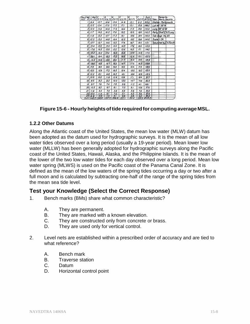
NAVEDTRA 14069A 15-8
Figure 15-6 - Hourly heights of tide required for computing average MSL.
1.2.2 Other Datums
Along the Atlantic coast of the United States, the mean low water (MLW) datum has been adopted as the datum used for hydrographic surveys. It is the mean of all low water tides observed over a long period (usually a 19-year period). Mean lower low water (MLLW) has been generally adopted for hydrographic surveys along the Pacific coast of the United States, Hawaii, Alaska, and the Philippine Islands. It is the mean of the lower of the two low water tides for each day observed over a long period. Mean low water spring (MLWS) is used on the Pacific coast of the Panama Canal Zone. It is defined as the mean of the low waters of the spring tides occurring a day or two after a full moon and is calculated by subtracting one-half of the range of the spring tides from the mean sea tide level.
Test your Knowledge (Select the Correct Response)
1. Bench marks (BMs) share what common characteristic?
A. They are permanent. B. They are marked with a known elevation. C. They are constructed only from concrete or brass. D. They are used only for vertical control.
2. Level nets are established within a prescribed order of accuracy and are tied to
what reference?
A. Bench mark B. Traverse station C. Datum D. Horizontal control point
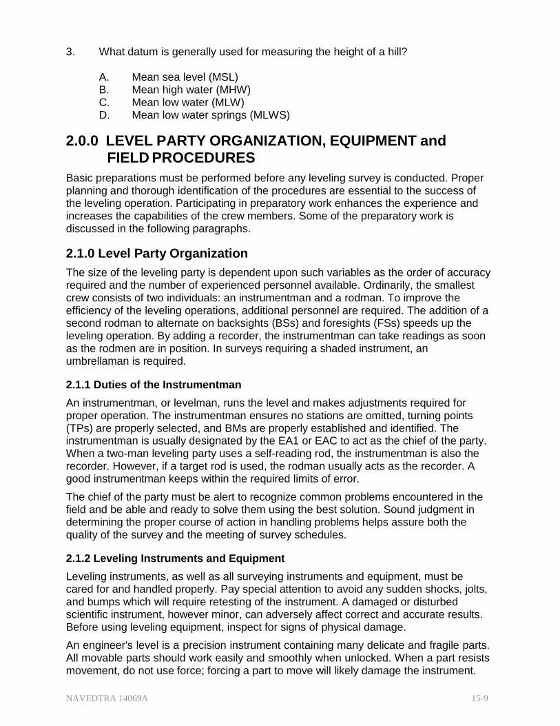
NAVEDTRA 14069A 15-9
3. What datum is generally used for measuring the height of a hill?
A. Mean sea level (MSL) B. Mean high water (MHW) C. Mean low water (MLW) D. Mean low water springs (MLWS)
2.0.0 LEVEL PARTY ORGANIZATION, EQUIPMENT and FIELD PROCEDURES
Basic preparations must be performed before any leveling survey is conducted. Proper planning and thorough identification of the procedures are essential to the success of the leveling operation. Participating in preparatory work enhances the experience and increases the capabilities of the crew members. Some of the preparatory work is discussed in the following paragraphs.
2.1.0 Level Party Organization
The size of the leveling party is dependent upon such variables as the order of accuracy required and the number of experienced personnel available. Ordinarily, the smallest crew consists of two individuals: an instrumentman and a rodman. To improve the efficiency of the leveling operations, additional personnel are required. The addition of a second rodman to alternate on backsights (BSs) and foresights (FSs) speeds up the leveling operation. By adding a recorder, the instrumentman can take readings as soon as the rodmen are in position. In surveys requiring a shaded instrument, an umbrellaman is required.
2.1.1 Duties of the Instrumentman
An instrumentman, or levelman, runs the level and makes adjustments required for proper operation. The instrumentman ensures no stations are omitted, turning points (TPs) are properly selected, and BMs are properly established and identified. The instrumentman is usually designated by the EA1 or EAC to act as the chief of the party. When a two-man leveling party uses a self-reading rod, the instrumentman is also the recorder. However, if a target rod is used, the rodman usually acts as the recorder. A good instrumentman keeps within the required limits of error.
The chief of the party must be alert to recognize common problems encountered in the field and be able and ready to solve them using the best solution. Sound judgment in determining the proper course of action in handling problems helps assure both the quality of the survey and the meeting of survey schedules.
2.1.2 Leveling Instruments and Equipment
Leveling instruments, as well as all surveying instruments and equipment, must be cared for and handled properly. Pay special attention to avoid any sudden shocks, jolts, and bumps which will require retesting of the instrument. A damaged or disturbed scientific instrument, however minor, can adversely affect correct and accurate results. Before using leveling equipment, inspect for signs of physical damage.
An engineer's level is a precision instrument containing many delicate and fragile parts. All movable parts should work easily and smoothly when unlocked. When a part resists movement, do not use force; forcing a part to move will likely damage the instrument.
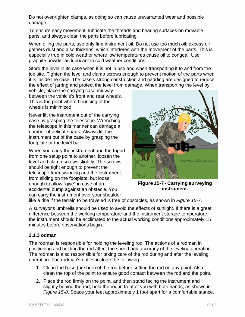
NAVEDTRA 14069A 15-10
Do not over-tighten clamps, as doing so can cause unwarranted wear and possible damage.
To ensure easy movement, lubricate the threads and bearing surfaces on movable parts, and always clean the parts before lubricating.
When oiling the parts, use only fine instrument oil. Do not use too much oil; excess oil gathers dust and also thickens, which interferes with the movement of the parts. This is especially true in cold weather where low temperatures cause oil to congeal. Use graphite powder as lubricant in cold weather conditions.
Store the level in its case when it is not in use and when transporting it to and from the job site. Tighten the level and clamp screws enough to prevent motion of the parts when it is inside the case. The case's strong construction and padding are designed to reduce the effect of jarring and protect the level from damage. When transporting the level by vehicle, place the carrying case midway between the vehicle's front and rear wheels. This is the point where bouncing of the wheels is minimized.
Never lift the instrument out of the carrying case by grasping the telescope. Wrenching the telescope in this manner can damage a number of delicate parts. Always lift the instrument out of the case by grasping the footplate or the level bar.
When you carry the instrument and the tripod from one setup point to another, loosen the level and clamp screws slightly. The screws should be tight enough to prevent the telescope from swinging and the instrument from sliding on the footplate, but loose enough to allow "give" in case of an accidental bump against an obstacle. You can carry the instrument over your shoulder
Figure 15-7 - Carrying surveying instrument.
like a rifle if the terrain to be traveled is free of obstacles, as shown in Figure 15-7.
A surveyor's umbrella should be used to avoid the effects of sunlight. If there is a great difference between the working temperature and the instrument storage temperature, the instrument should be acclimated to the actual working conditions approximately 15 minutes before observations begin.
2.1.3 odman
The rodman is responsible for holding the leveling rod. The actions of a rodman in positioning and holding the rod affect the speed and accuracy of the leveling operation. The rodman is also responsible for taking care of the rod during and after the leveling operation. The rodman's duties include the following:
1. Clean the base (or shoe) of the rod before setting the rod on any point. Also clean the top of the point to ensure good contact between the rod and the point.
2. Place the rod firmly on the point, and then stand facing the instrument and slightly behind the rod; hold the rod in front of you with both hands, as shown in Figure 15-8. Space your feet approximately 1 foot apart for a comfortable stance.
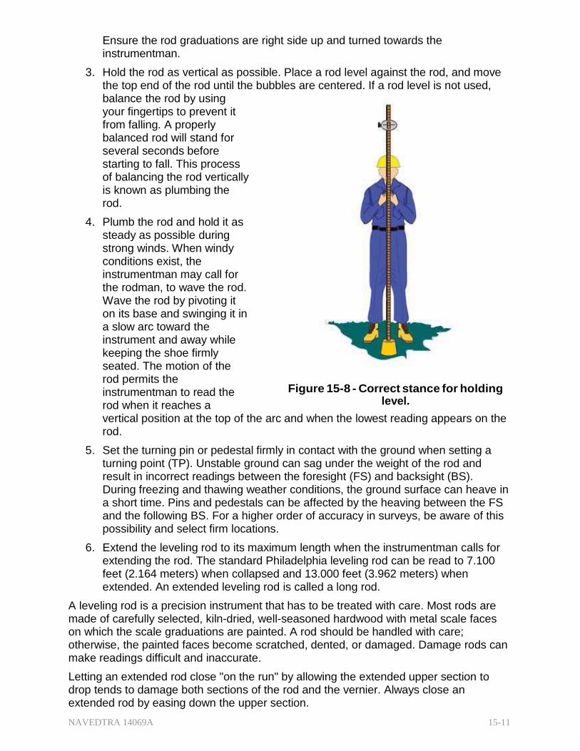
NAVEDTRA 14069A 15-11
Ensure the rod graduations are right side up and turned towards the instrumentman.
3. Hold the rod as vertical as possible. Place a rod level against the rod, and move the top end of the rod until the bubbles are centered. If a rod level is not used, balance the rod by using your fingertips to prevent it from falling. A properly balanced rod will stand for several seconds before starting to fall. This process of balancing the rod vertically is known as plumbing the rod.
4. Plumb the rod and hold it as steady as possible during strong winds. When windy conditions exist, the instrumentman may call for the rodman, to wave the rod. Wave the rod by pivoting it on its base and swinging it in a slow arc toward the instrument and away while keeping the shoe firmly seated. The motion of the rod permits the instrumentman to read the rod when it reaches a
Figure 15-8 - Correct stance for holding level.
vertical position at the top of the arc and when the lowest reading appears on the rod.
5. Set the turning pin or pedestal firmly in contact with the ground when setting a turning point (TP). Unstable ground can sag under the weight of the rod and result in incorrect readings between the foresight (FS) and backsight (BS). During freezing and thawing weather conditions, the ground surface can heave in a short time. Pins and pedestals can be affected by the heaving between the FS and the following BS. For a higher order of accuracy in surveys, be aware of this possibility and select firm locations.
6. Extend the leveling rod to its maximum length when the instrumentman calls for extending the rod. The standard Philadelphia leveling rod can be read to 7.100 feet (2.164 meters) when collapsed and 13.000 feet (3.962 meters) when extended. An extended leveling rod is called a long rod.
A leveling rod is a precision instrument that has to be treated with care. Most rods are made of carefully selected, kiln-dried, well-seasoned hardwood with metal scale faces on which the scale graduations are painted. A rod should be handled with care; otherwise, the painted faces become scratched, dented, or damaged. Damage rods can make readings difficult and inaccurate.
Letting an extended rod close "on the run" by allowing the extended upper section to drop tends to damage both sections of the rod and the vernier. Always close an extended rod by easing down the upper section.
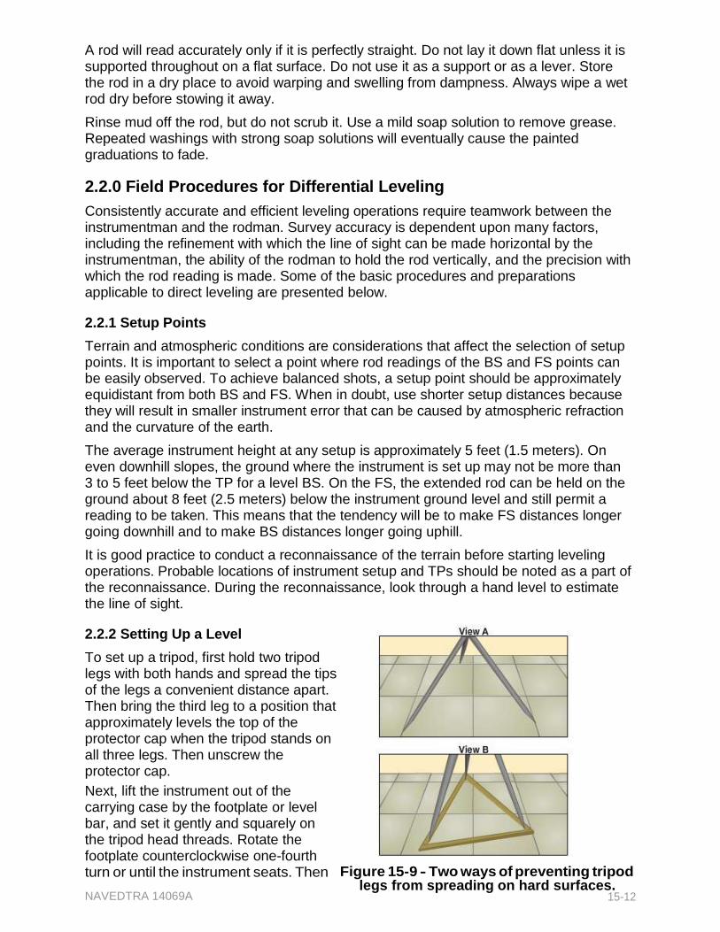
A rod will read accurately only if it is perfectly straight. Do not lay it down flat unless it is supported throughout on a flat surface. Do not use it as a support or as a lever. Store the rod in a dry place to avoid warping and swelling from dampness. Always wipe a wet rod dry before stowing it away.
Rinse mud off the rod, but do not scrub it. Use a mild soap solution to remove grease. Repeated washings with strong soap solutions will eventually cause the painted graduations to fade.
2.2.0 Field Procedures for Differential Leveling
Consistently accurate and efficient leveling operations require teamwork between the instrumentman and the rodman. Survey accuracy is dependent upon many factors, including the refinement with which the line of sight can be made horizontal by the instrumentman, the ability of the rodman to hold the rod vertically, and the precision with which the rod reading is made. Some of the basic procedures and preparations applicable to direct leveling are presented below.
2.2.1 Setup Points
Terrain and atmospheric conditions are considerations that affect the selection of setup points. It is important to select a point where rod readings of the BS and FS points can be easily observed. To achieve balanced shots, a setup point should be approximately equidistant from both BS and FS. When in doubt, use shorter setup distances because they will result in smaller instrument error that can be caused by atmospheric refraction and the curvature of the earth.
The average instrument height at any setup is approximately 5 feet (1.5 meters). On even downhill slopes, the ground where the instrument is set up may not be more than 3 to 5 feet below the TP for a level BS. On the FS, the extended rod can be held on the ground about 8 feet (2.5 meters) below the instrument ground level and still permit a reading to be taken. This means that the tendency will be to make FS distances longer going downhill and to make BS distances longer going uphill.
It is good practice to conduct a reconnaissance of the terrain before starting leveling operations. Probable locations of instrument setup and TPs should be noted as a part of the reconnaissance. During the reconnaissance, look through a hand level to estimate the line of sight.
2.2.2 Setting Up a Level
To set up a tripod, first hold two tripod legs with both hands and spread the tips of the legs a convenient distance apart. Then bring the third leg to a position that approximately levels the top of the protector cap when the tripod stands on all three legs. Then unscrew the protector cap.
Next, lift the instrument out of the carrying case by the footplate or level bar, and set it gently and squarely on the tripod head threads. Rotate the footplate counterclockwise one-fourth turn or until the instrument seats. Then Figure 15-9 - Two ways of preventing tripod
NAVEDTRA 14069A legs from spreading on hard surfaces.
15-12
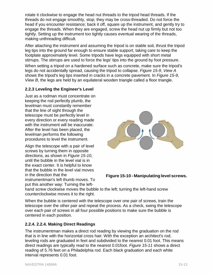
NAVEDTRA 14069A 15-13
rotate it clockwise to engage the head nut threads to the tripod head threads. If the threads do not engage smoothly, stop; they may be cross-threaded. Do not force the head if you encounter resistance; back it off, square up the instrument, and gently try to engage the threads. When they are engaged, screw the head nut up firmly but not too tightly. Setting up the instrument too tightly causes eventual wearing of the threads, making unthreading difficult.
After attaching the instrument and assuming the tripod is on stable soil, thrust the tripod leg tips into the ground far enough to ensure stable support, taking care to keep the footplate approximately level. Some tripods have legs equipped with short metal stirrups. The stirrups are used to force the legs' tips into the ground by foot pressure.
When setting a tripod on a hardened surface such as concrete, make sure the tripod's legs do not accidentally spread, causing the tripod to collapse. Figure 15-9, View A shows the tripod's leg tips inserted in cracks in a concrete pavement. In Figure 15-9, View B, the legs are held by an equilateral wooden triangle called a floor triangle.
2.2.3 Leveling the Engineer's Level
Just as a rodman must concentrate on keeping the rod perfectly plumb, the levelman must constantly remember that the line of sight through the telescope must be perfectly level in every direction or every reading made with the instrument will be inaccurate. After the level has been placed, the levelman performs the following procedures to level the instrument.
Align the telescope with a pair of level screws by turning them in opposite directions, as shown in Figure 15-10, until the bubble in the level vial is in the exact center. It is helpful to know that the bubble in the level vial moves in the direction that the instrumentman's left thumb moves. To put this another way: Turning the left-
Figure 15-10 - Manipulating level screws.
hand screw clockwise moves the bubble to the left; turning the left-hand screw counterclockwise moves it to the right.
When the bubble is centered with the telescope over one pair of screws, train the telescope over the other pair and repeat the process. As a check, swing the telescope over each pair of screws in all four possible positions to make sure the bubble is centered in each position.
2.2.4. 2.2.4. Making Direct Readings
The instrumentman makes a direct rod reading by viewing the graduation on the rod that is in line with the horizontal cross hair. With the exception an architect's rod, leveling rods are graduated in feet and subdivided to the nearest 0.01 foot. This means direct readings are typically read to the nearest 0.01foot. Figure 15-11 shows a direct reading of 5.76 feet on a Philadelphia rod. Each black graduation and each white interval represents 0.01 foot.
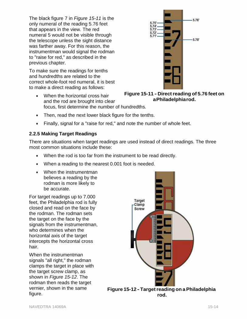
NAVEDTRA 14069A 15-14
The black figure 7 in Figure 15-11 is the only numeral of the reading 5.76 feet that appears in the view. The red numeral 5 would not be visible through the telescope unless the sight distance was farther away. For this reason, the instrumentman would signal the rodman to "raise for red," as described in the previous chapter.
To make sure the readings for tenths and hundredths are related to the correct whole-foot red numeral, it is best to make a direct reading as follows:
When the horizontal cross hair and the rod are brought into clear
Figure 15-11 - Direct reading of 5.76 feet on
a Philadelphia rod.
focus, first determine the number of hundredths.
Then, read the next lower black figure for the tenths.
Finally, signal for a "raise for red," and note the number of whole feet.
2.2.5 Making Target Readings
There are situations when target readings are used instead of direct readings. The three most common situations include these:
When the rod is too far from the instrument to be read directly.
When a reading to the nearest 0.001 foot is needed.
When the instrumentman believes a reading by the rodman is more likely to be accurate.
For target readings up to 7.000 feet, the Philadelphia rod is fully closed and read on the face by the rodman. The rodman sets the target on the face by the signals from the instrumentman, who determines when the horizontal axis of the target intercepts the horizontal cross hair.
When the instrumentman signals "all right," the rodman clamps the target in place with the target screw clamp, as shown in Figure 15-12. The rodman then reads the target vernier, shown in the same figure.
Figure 15-12 - Target reading on a Philadelphia rod.
NAVEDTRA 14069A 15-15
The reading to the nearest 0.01 foot is indicated by the zero on the vernier. In Figure 15-12, the vernier zero indicates a reading of a few thousandths of a foot more than 5.84 feet. To determine how many thousandths over 5.84 feet, examine the graduations on the vernier to determine the one most exactly in line with a graduation on the rod. In Figure 15-12, this is the 0.003-foot graduation; therefore, the reading to the nearest 0.001 foot is 5.843 feet.
For target readings of more than 7.000 feet, the Philadelphia rod is extended and the rodman makes the reading on the back of the rod. In Figure 15-13, the back of the upper section of the rod is shown, graduated from the top down, from 7.000 feet through 13.000 feet. A rod vernier on the back also can be seen fixed to the top of the lower section of the rod, also read from the top down.
For a target reading of more than 7.000 feet, the rodman, on receiving the signal to "extend the rod," fixes the target on the face of the upper section all the way to the top of the upper section. While doing this, the rodman makes sure the target vernier is set at exactly the same reading indicated by the rod vernier on
Figure 15-13 - Reading on the back of a Philadelphia rod.
the back of the rod; the rodman then releases the rod screw clamp and slides the upper section of the rod slowly upwards until the instrumentman gives the signal "all right." When the horizontal axis of the target reaches the level where it is intersected by the horizontal cross hair, the instrumentman gives the signal.
2.3.0 Fundamental Leveling Procedures
The following example explains the basic procedure for determining elevations during a leveling operation.
In Figure 15-14, there is a BM at Point A with a known elevation of 365.01 feet and a Point B whose elevation needs to be determined. To determine Point B's elevation, first set up and level the engineer's level approximately half-way between Points A and B. Next, level the instrument. After the instrument is leveled the instrumentman has a perfectly level line of sight that can be rotated around the horizon.
NAVEDTRA 14069A 15-16
Figure 15-14 - Direct leveling procedure.
After the instrument is leveled, the line of sight elevation must be determined. Line of sight elevation or height of instrument (HI) is calculated by adding the known elevation (KE) and the backsight (BS) height. In this example, the known elevation of the BM (Point A) is 365.01 feet and the BS height (the rod reading) is 11.56 feet. Therefore, the BM elevation 365.01 plus the BS rod reading of 11.56 equals an HI of 376.57 feet. This means whichever direction the telescope is pointing, all points on the horizon intercepted by the horizontal cross hair have an elevation of 376.57 feet.
To determine the ground elevation at Point B, the instrumentman takes a foresight (FS) on a rod held at Point B. In this example, the rod reading is 1.42 feet. Because the elevation of the line of sight (HI) is 376.57 feet, the ground elevation at Point B is the HI minus the rod reading, or 376.57 - 1.42, which equals 375.15 feet.
2.3.1 Balancing Shots
The balancing of the FS and BS distances is important in leveling. The effect of curvature and refraction may be eliminated by balancing BS and FS distances; however, instrumental error is a far more important reason for careful balancing.
"Balancing shots" means equalizing as much as possible BS and FS distances by selecting turning points that are approximately an equal distance from both the BS and FS points.
No matter how carefully a telescope is leveled, it is likely to be slightly out of the horizontal. The possibility of inaccurate reading increases as the length of the sight increases. When the BS distance differs from the FS distance, the BS and FS errors will differ. If the distances are the same, the errors will be the same. Therefore, balancing shots eliminates the effect of instrument error.
To achieve balanced shots, pace off an equal number of steps for the BS and FS. The BS and FS distances should be kept under 300 feet except when necessary to pass or cross an obstacle.
2.3.2 tablishing Turning Points
Suppose the elevation of a point at the summit of a long slope needs to be determined, and the nearest BM is at the foot of the slope some 30 feet or so below the summit. To determine an elevation in this situation, turning points (TPs) as displayed in Figure 15-
NAVEDTRA 14069A 15-17
15 must be used. A turning point is defined as a point on which both a minus sight (FS) and a plus sight (BS) are taken on a line of direct levels.
Figure 15-15 -Turning points.
Assume the elevation of the BM in Figure 15-15 is correct. The accuracy of the summit elevation is dependent on how accurately the elevation of each intermediate TP is determined. This accuracy depends upon a number of factors, the most important of which include the following:
1. FS and BS distances should not exceed 300 feet when leveling with ordinary precision. Therefore, the first setup point for the instrument should be not more than 300 feet from the BM, and the first TP should be not more than 300 feet from the instrument. To balance shots, place the instrument approximately the same distance from the BM as the distance to TP1.
2. At the first setup point, a rod held on the BM and a rod held at TP1 must be viewable.
3. Setup points should be used that make rod readings as small as possible.
4. A TP must be visible, accessible, and stable. It must be firm enough to support the base of the rod. Using unstable ground can result in progressive errors in subsequent readings.
When the use of a point in unstable ground is unavoidable, use a turning point pin or turning point plate. Drive a pin into the ground to mark the turning point. If a regular pin is not available, you may substitute a marlinspike or a railroad spike. If the soil is too soft, use a plate to support a driven pin.
Test your Knowledge (Select the Correct Response)
4. What type of lubricant is recommended for use on engineer's levels in arctic regions?
A. Watch oil B. Powdered graphite C. Petroleum jelly D. Mineral oil
NAVEDTRA 14069A 15-18
5. When a level setup must be transferred to another point or station, what screws should be loosened slightly?
A. Leg and level B. Leg and clamp C. Level and clamp D. Tangent and clamp
6. To help the instrumentman obtain accurate readings, the rodman should take
which of the following actions?
A. Cleaning the top of the point and the rod shoe for a good contact B. Plumbing with both hands C. Making sure the rod graduations are right side up and facing the
instrumentman D. All of the above
7. The proper care of a leveling rod includes which of the following actions?
A. Supporting the entire rod on a flat surface when laying the rod down flat B. Rinsing any mud off with water and cleaning any grease off with a mild
soap solution C. Wiping it dry before storing it in a dry place D. All of the above
8. In determining the elevation of an unknown point, what arithmetic operation
should you apply to the HI and FS?
A. Addition B. Subtraction C. Multiplication D. Division
9. When turning points are located in sandy soil, you must set the level rod on a
base. Which of the following bases is an acceptable choice?
A. A turning point plate B. A turning point pin driven into the soil C. A marlinspike driven into the soil D. All of the above
3.0.0 METHODS of LEVELING
Leveling methods are subdivided into two major categories: direct and indirect. Direct leveling describes the method of measuring vertical distance (difference in elevation) directly with the use of precise or semi-precise leveling instruments. Indirect leveling is the measurement of vertical distances indirectly or by using computation. Unlike direct leveling operations, indirect leveling operations do not depend on lines of sight or visibility of points or stations. Two of the surveying instruments used for indirect leveling are the transit and the theodolite.
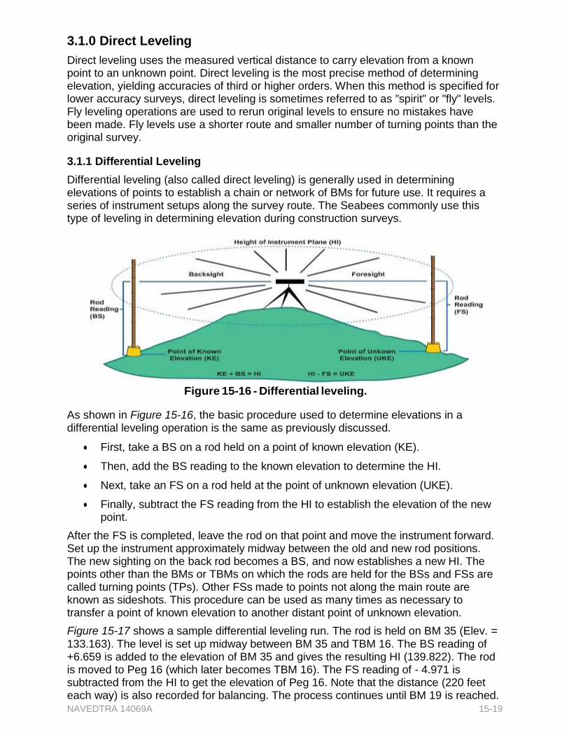
NAVEDTRA 14069A 15-19
3.1.0 Direct Leveling
Direct leveling uses the measured vertical distance to carry elevation from a known point to an unknown point. Direct leveling is the most precise method of determining elevation, yielding accuracies of third or higher orders. When this method is specified for lower accuracy surveys, direct leveling is sometimes referred to as "spirit" or "fly" levels. Fly leveling operations are used to rerun original levels to ensure no mistakes have been made. Fly levels use a shorter route and smaller number of turning points than the original survey.
3.1.1 Differential Leveling
Differential leveling (also called direct leveling) is generally used in determining elevations of points to establish a chain or network of BMs for future use. It requires a series of instrument setups along the survey route. The Seabees commonly use this type of leveling in determining elevation during construction surveys.
Figure 15-16 - Differential leveling.
As shown in Figure 15-16, the basic procedure used to determine elevations in a differential leveling operation is the same as previously discussed.
First, take a BS on a rod held on a point of known elevation (KE).
Then, add the BS reading to the known elevation to determine the HI.
Next, take an FS on a rod held at the point of unknown elevation (UKE).
Finally, subtract the FS reading from the HI to establish the elevation of the new point.
After the FS is completed, leave the rod on that point and move the instrument forward. Set up the instrument approximately midway between the old and new rod positions. The new sighting on the back rod becomes a BS, and now establishes a new HI. The points other than the BMs or TBMs on which the rods are held for the BSs and FSs are called turning points (TPs). Other FSs made to points not along the main route are known as sideshots. This procedure can be used as many times as necessary to transfer a point of known elevation to another distant point of unknown elevation.
Figure 15-17 shows a sample differential leveling run. The rod is held on BM 35 (Elev. = 133.163). The level is set up midway between BM 35 and TBM 16. The BS reading of +6.659 is added to the elevation of BM 35 and gives the resulting HI (139.822). The rod is moved to Peg 16 (which later becomes TBM 16). The FS reading of - 4.971 is subtracted from the HI to get the elevation of Peg 16. Note that the distance (220 feet each way) is also recorded for balancing. The process continues until BM 19 is reached.

NAVEDTRA 14069A 15-20
3.2.0 Level Computations
When making level computations, check the notes for a level run to ensure the correct BM and elevation are used. Then, check the arithmetical accuracy where BSs are added and FSs are subtracted. The difference between the sum of the BSs taken on BMs or TPs and the sum of the FSs taken on BMs or TPs should equal the difference in elevation between the initial BM or TP and the final BM or TP.
Balanced BS and FS distances are shown in Figure 15-17. The distance used for the first instrument setup was 220 feet. The first BS (rod reading on 35) was 6.659 feet. The first FS (rod reading on 16) was 4.971. Notice that the plus sign (+) appears at the top of the BS column and that the minus sign (-) appears at the top of the FS column in the field notebook. This serves as reminder that BSs are added and FSs are subtracted as new elevations are computed.
The BS taken on a point added to the elevation of the point gives the HI. This establishes the elevation of the line of sight so that an FS can then be taken on any point (BM, TBM, or TP).
The elevation of 35 is 133.163 feet. The first HI is
133.163 + 6.659 = 139.822 feet.
The FS subtracted from the HI,
139.822 - 4.971 = 134.851 feet,
which is the elevation of 16.
Following through with a similar computation for each setup, notice the elevation of 19 is 136.457 feet.
Look now at the notes in Figure 15-17. The sum of all the BSs is 24.620 feet. The sum of all the FSs is 21.326 feet. The difference between the sum of the BSs and the sum of the FSs is
24.620 - 21.326 = 3.294 feet.
This difference should agree with the difference between the actual elevation of BM 35 and the elevation already found for BM 19, which is 136.457 - 133.163 = 3.294 feet.
This provides a check on the step-by-step computation of elevations.
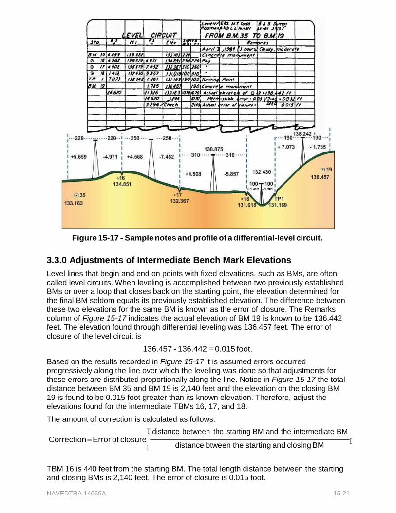
NAVEDTRA 14069A 15-21
Figure 15-17 - Sample notes and profile of a differential-level circuit.
3.3.0 Adjustments of Intermediate Bench Mark Elevations
Level lines that begin and end on points with fixed elevations, such as BMs, are often called level circuits. When leveling is accomplished between two previously established BMs or over a loop that closes back on the starting point, the elevation determined for the final BM seldom equals its previously established elevation. The difference between these two elevations for the same BM is known as the error of closure. The Remarks column of Figure 15-17 indicates the actual elevation of BM 19 is known to be 136.442 feet. The elevation found through differential leveling was 136.457 feet. The error of closure of the level circuit is
136.457 - 136.442 = 0.015 foot.
Based on the results recorded in Figure 15-17 it is assumed errors occurred progressively along the line over which the leveling was done so that adjustments for these errors are distributed proportionally along the line. Notice in Figure 15-17 the total distance between BM 35 and BM 19 is 2,140 feet and the elevation on the closing BM 19 is found to be 0.015 foot greater than its known elevation. Therefore, adjust the elevations found for the intermediate TBMs 16, 17, and 18.
The amount of correction is calculated as follows:
distance between the starting BM and the intermediate BMCorrection Error of closure
distance btween the starting and closing BM
TBM 16 is 440 feet from the starting BM. The total length distance between the starting and closing BMs is 2,140 feet. The error of closure is 0.015 foot.
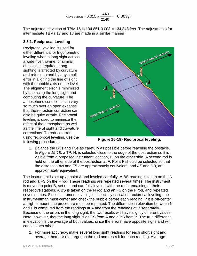
NAVEDTRA 14069A 15-22
Correction 0.015 x 440
2140 0.003 ft
The adjusted elevation of TBM 16 is 134.851-0.003 = 134.848 feet. The adjustments for intermediate TBMs 17 and 18 are made in a similar manner.
3.3.1. Reciprocal Leveling
Reciprocal leveling is used for either differential or trigonometric leveling when a long sight across a wide river, ravine, or similar obstacle is required. Long sighting is affected by curvature and refraction and by any small error in aligning the line of sight with the bubble axis on the level. The alignment error is minimized by balancing the long sight and computing the curvature. The atmospheric conditions can vary so much over an open expanse that the refraction correction can also be quite erratic. Reciprocal leveling is used to minimize the effect of the atmosphere as well as the line of sight and curvature corrections. To reduce error using reciprocal leveling, use the following procedures:
Figure 15-18 - Reciprocal leveling.
1. Balance the BSs and FSs as carefully as possible before reaching the obstacle. In Figure 15-18, a TP, N, is selected close to the edge of the obstruction so it is visible from a proposed instrument location, B, on the other side. A second rod is held on the other side of the obstruction at F. Point F should be selected so that the distances AN and FB are approximately equivalent, and AF and NB, are approximately equivalent.
The instrument is set up at point A and leveled carefully. A BS reading is taken on the N rod and a FS on the F rod. These readings are repeated several times. The instrument is moved to point B, set up, and carefully leveled with the rods remaining at their respective stations. A BS is taken on the N rod and an FS on the F rod, and repeated several times. Since instrument leveling is especially critical on reciprocal leveling, the instrumentman must center and check the bubble before each reading. If it is off-center a slight amount, the procedure must be repeated. The difference in elevation between N and F is computed from the readings at A and from the readings at B separately. Because of the errors in the long sight, the two results will have slightly different values. Note, however, that the long sight is an FS from A and a BS from B. The true difference in elevation is the average of both values, since the errors have opposite signs and will cancel each other.
2. For more accuracy, make several long sight readings for each short sight and average them. Use a target on the rod and reset it for each reading. Average
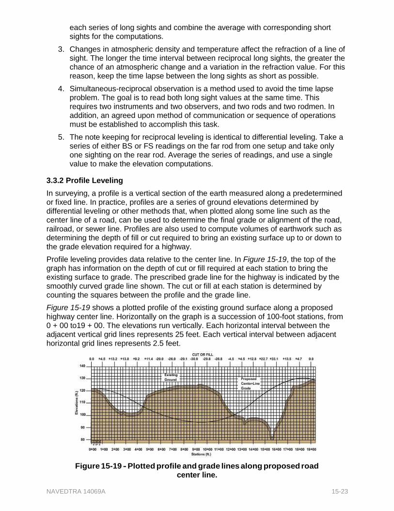
NAVEDTRA 14069A 15-23
each series of long sights and combine the average with corresponding short sights for the computations.
3. Changes in atmospheric density and temperature affect the refraction of a line of sight. The longer the time interval between reciprocal long sights, the greater the chance of an atmospheric change and a variation in the refraction value. For this reason, keep the time lapse between the long sights as short as possible.
4. Simultaneous-reciprocal observation is a method used to avoid the time lapse problem. The goal is to read both long sight values at the same time. This requires two instruments and two observers, and two rods and two rodmen. In addition, an agreed upon method of communication or sequence of operations must be established to accomplish this task.
5. The note keeping for reciprocal leveling is identical to differential leveling. Take a series of either BS or FS readings on the far rod from one setup and take only one sighting on the rear rod. Average the series of readings, and use a single value to make the elevation computations.
3.3.2 Profile Leveling
In surveying, a profile is a vertical section of the earth measured along a predetermined or fixed line. In practice, profiles are a series of ground elevations determined by differential leveling or other methods that, when plotted along some line such as the center line of a road, can be used to determine the final grade or alignment of the road, railroad, or sewer line. Profiles are also used to compute volumes of earthwork such as determining the depth of fill or cut required to bring an existing surface up to or down to the grade elevation required for a highway.
Profile leveling provides data relative to the center line. In Figure 15-19, the top of the graph has information on the depth of cut or fill required at each station to bring the existing surface to grade. The prescribed grade line for the highway is indicated by the smoothly curved grade line shown. The cut or fill at each station is determined by counting the squares between the profile and the grade line.
Figure 15-19 shows a plotted profile of the existing ground surface along a proposed highway center line. Horizontally on the graph is a succession of 100-foot stations, from 0 + 00 to19 + 00. The elevations run vertically. Each horizontal interval between the adjacent vertical grid lines represents 25 feet. Each vertical interval between adjacent horizontal grid lines represents 2.5 feet.
Figure 15-19 - Plotted profile and grade lines along proposed road center line.
NAVEDTRA 14069A 15-24
The profile is plotted through a succession of points, each of which was identified from a profile elevation taken on the ground. Figure 15-20 shows field notes for the levels taken from 0 + 00 through 10 + 00.
Figure 15-20 - Field notes for profile levels shown in Figure 15-19.
The level was first set up at a point approximately equidistant from station 0 + 00 and from a BM identified as National Geodetic Survey Monument, Bradley, Missouri. The elevation of the BM was 117.51 feet. The first backsight reading on a rod held on the BM was 7.42 feet. Therefore, the HI which is entered into the HI column of the field notes is
117.51 + 7.42 = 124.93 feet.
From the first instrument setup, FSs were taken on station 0 + 00 and 1 + 00. The elevation of the station in each case was determined by subtracting the FS reading from the HI. Note that the FS taken on station 1 + 00 is entered in a column headed FS, while the one taken on station 0 + 00 is entered in a different column, headed IFS. IFS is an intermediate FS, or an FS taken on a point that is neither a BM nor a TP. Station 1 + 00 is used as a TP in shifting the instrument ahead. Only FSs taken on BMs or TPs are entered in the column headed FS.
After an FS was taken on station 1 + 00, it became necessary to shift the instrument ahead. Station 1 + 00 was used as the TP. From the new instrument setup, a BS was taken on a rod held on 1 + 00. The new HI was found by adding the BS reading to the previously determined elevation of 1 + 00.
From the new setup, an FS was taken on station 2 + 00; again, the elevation was found by subtracting the FS reading from the HI. After this sight was taken, the instrument was again shifted ahead, probably because of the steepness of the slope. This time, station 2 + 00 was used as the TP2. From the new setup, a BS was taken on station 2 + 00 and
a new HI established. From this setup, it was possible to take FSs on both station 3 + 00 and station 4 + 00. Because station 3 + 00 was not used as a TP, the FS on it was entered under IFS.
Apparently, the slope between station 4 + 00 and station 5 + 00 was so steep that sighting both stations from the same setup with the rod being used was impossible. Consequently, an intermediate TP (TP4) was established at station 4 + 75 by determining the elevation of this station. The instrument was shifted to a setup from which a BS could be obtained on a rod held on this station and from which FSs on stations 5 + 00, 6 + 00, 7 + 00, and 8 + 00 could be taken. Station 8 + 00 was then used as a TP for the last shift ahead. From this last setup, it was possible to take FSs on stations 9 + 00 and 10 + 00.
As a check on the arithmetic, recheck each page of level notes to check the difference between the sum of the FSs and the sum of the BSs against the difference in elevation between the initial BM or TP and final BM or TP. Obviously, only the BSs and FSs taken on BMs and TPs are relevant to this check. This is why intermediate FSs not taken on BMs or TPs are entered in a separate column.
If the arithmetic is correct, the two differences will be the same. As can be seen, the sum of the relevant BSs in Figure 15-20 is 39.63, the sum of the FSs is 27.70, and the difference between the two is 11.93. Note that from this difference, the BS taken on TP5 is deducted. The reason is the fact that this BS is not offset by a corresponding FS on a BM or TP. With the BS taken on TP5 deducted, the difference between the sum of the FSs and the sum of the BSs is 6.86. The difference between the elevation of TP5 and the elevation of the initial BM is 6.86, so the arithmetic checks.
Remember, this procedure provides a check on the arithmetic only. If incorrect values are recorded, the arithmetic will check out as if the correct values had been recorded.
3.3.3 Cross-section Leveling
Just as Profile leveling is used to determine the elevations of a series of points lengthwise along a highway, Cross-section leveling is used to determine the elevations of points on a succession of lines running at right angles or perpendicular to a lengthwise line of the highway.
Cross-section lines are established at regular stations, at any plus stations, and at intermediate breaks in the ground. Short cross lines are laid out by eye. Long cross lines are laid out at a 90° angle to the center line with the transit. For short cross lines, most surveyors prefer to use an angle prism for sighting 90° angles from the center line.
For cross-section leveling and strip topography, it is necessary to lay off a 90° angle at numerous points along a center line. Surveyors can often establish the 90° angle with sufficient accuracy by estimation. Straddle a point on the line and then, extending your arms sideways along the marked line, as shown in Figure 15-21, look alternately right and left, and adjust your foot position until your body is in line with AB. Then bring your hands together in front of you, pointing along an approximate 90° line from the marked line. Experienced surveyors can lay off a 90° angle using this Figure 15-21 -Laying off a 900 angle
NAVEDTRA 14069A from the center line stakes 15-25
Recommended