Embed Size (px)
Citation preview
ZELTEX-440
USER'S MANUALVersion 1.2
Zeltex, Inc.130 Western Maryland
ParkwayHagerstown, MD 21740 USA
Phone: 301-791-7080 or 800-732-1950
FAX: 301-733-9398
© 2001, Zeltex, Inc.
This manual may not be reproduced or copied by any means without specific written permission of Zeltex, Inc.

i
ZELTEX-440 MANUALTABLE OF CONTENTS
INTRODUCTION.......................................................................................1.1 DESCRIPTION..............................................................................1.2 BACKGROUND............................................................................1.3 MAJOR COMPONENTS.................................................................1.4 UNPACKING................................................................................1.5 SYSTEM SET-UP..........................................................................
BASIC OPERATION..................................................................................2.1 TURN THE POWER SWITCH ON....................................................2.2 ZELTEX-440 MODES OF OPERATION...........................................
FIELD SETTINGS......................................................................................3.1 INTRODUCTION..........................................................................3.2 PASSWORD.................................................................................3.3 THE FIELD SETTINGS..................................................................
1. CONFIGURATION.................................................................2. PERIPHERALS......................................................................3. PRODUCTS..........................................................................4. CONSTITUENTS...................................................................5. CHANGE PASSWORD...........................................................6. MATH TERMS......................................................................7. THE MEMORY CARD............................................................8. CALIBRATION......................................................................9. ADJUSTMENT.......................................................................
TEST MODE..............................................................................................4.1 INTRODUCTION.......................................................................4.2 SAMPLE "TEST" MEASUREMENT............................................
TROUBLE-SHOOTING..............................................................................CALIBRATION OR RESEARCH PROTOCOL.............................................SYSTEM DESCRIPTION...........................................................................APPENDIX III...........................................................................................

ii
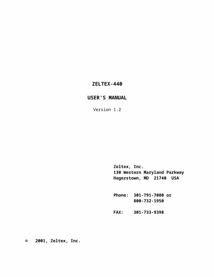
WARNING
THE ZX440 PORTABLE FUEL ANALYZERS ARE NOT EXPLOSION PROOF.
REASONABLE CARE MUST BE USED IN HANDLING THESE INSTRUMENTS.
ALL SAMPLES NEED TO BE ENCLOSED IN SAMPLE HOLDERS FOR SAFETY.
iii
JAR PROCEDURE FOR PROPER READINGS
• Clean jars inside and out with alcohol or soap and water. Dry thoroughly before use. Note that acetone may be used, but avoid getting acetone on jar label.
• Check to assure jar label is not peeling or torn. (Replacement labels are available.
• Make sure inside of sample chamber is clean. Use a small amount of alcohol or soapy water on a paper towel or cotton swab. Do not use acetone in the chamber. After cleaning, use talcum powder to lightly dust inside chamber, removing any excess powder. This will make it easier to set the jar all the way down in the chamber and to turn it for the second reading.
• Be sure that the windows in the chamber are clean and free of obstructions.
CAUTIONS:
• Never use jars without lids.
• Never pour gasoline into jar while jar is in sample chamber.
• Always fill jar to the fill line.
1
SECTION I
INTRODUCTION
1.1 DESCRIPTION
The ZELTEX-440 Near-Infrared (NIR) Petroleum Analyzer is a laboratory instrument intended for use in monitoring and research of petroleum products and other homogeneous liquids. Once calibrated for a specific product, the ZELTEX-440 will provide quick, accurate analysis of the constituents of interest in your product.
1.2 BACKGROUND
The ZELTEX-440 employs near-infrared quantitative analysis, a technology first developed by the U. S. Dept. of Agriculture.1,2
Near-infrared quantitative analysis uses low level electromagnetic radiation in the 604nm to 1050nm wavelength range. The light waves are in the non-ionizing range and are, therefore, non-damaging to the product. (In the ZELTEX-440, the intensity of the light is equivalent to a 60 watt light bulb approximately 20 feet away.
Near-infrared absorption can be analyzed by measuring the light that is reflected from (a substance) or transmitted through a substance. Near-infrared measures "light interactance" which is a combination of the reflected and transmitted light.
Infrared light interactance analysis was developed at the U.S. Department of Agriculture.3,4,5 Near-infrared quantitative measurement is an established method of determining chemical composition. The agricultural community has used near-infrared technology since the early 1970s to analyze forage and food products.6,7 Quantitative near-infrared instruments provide rapid, accurate measurement of nutritional constituents. NIR technology now is widely used in quality control functions in the food and grain industries.
Chemical constituents such as protein, oil/fat, octane, Cetane, etc. can
be measured due to their characteristic absorption bands that are related to the stretching and bending of hydrogen bonds associated with nitrogen,

2
carbon, and oxygen. Figure 1.1 illustrates some of these absorption bands and Table 1 lists the absorption peaks.
The amount of light that is absorbed is influenced by the path length (l) of the irradiating energy through the sample, the molar concentration of the substance (c), and the molar absorption coefficient (also called molar extinction coefficient) (k). The relationship of these parameters is expressed in the Beer/Lambert Law:8
I = Io10-kcl
or
I = log10(Io/I) = kcl
I is equal to the intensity of energy emerging from the sample and Io is the intensity of energy that is projected into the sample. Absorption data are generally reported as absorbance, A, (log Io/I). The amount of absorption can be described in terms of transmittance (T):
T = I/Io, thus A = log10(1/T) = kcl
If one is measuring reflectance (R), Beer's law can be expressed as follows:
A = log10 (1/R) = kcl
Likewise with interactance (I):
A = log10 (1/I) = kcl
As a substance absorbs more light, the intensity of energy emerging from the sample decreases, thus, the value for log10(1/T) increases. The more opaque the sample, the more light it will absorb yielding a higher value for log10(1/T). Likewise, the more transparent a sample the less light it will absorb, thus yielding a lower value for log9(1/T).
3
Section I Introduction___________________________________________________________
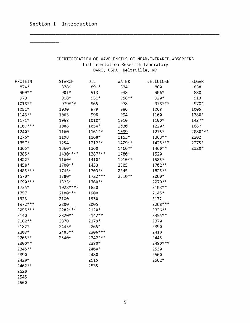
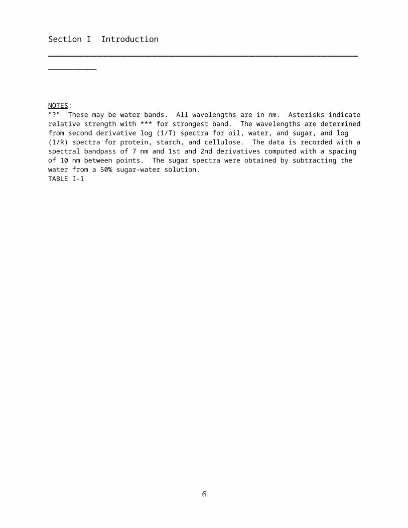
IDENTIFICATION OF WAVELENGTHS OF NEAR-INFRARED ABSORBERSInstrumentation Research Laboratory
BARC, USDA, Beltsville, MD
PROTEIN STARCH OIL WATER CELLULOSE SUGAR 874* 878* 891* 834* 860 838 909** 901* 913 938 906* 888 979 918* 931* 958** 920* 913 1018** 979*** 965 978 978*** 978* 1051* 1030 979 986 1068 1005 1143** 1063 998 994 1160 1380* 1171* 1068 1018* 1010 1190* 1437* 1167*** 1088 1054* 1030 1220* 1687 1240* 1160 1161** 1099 1275* 2080*** 1276* 1198 1168* 1153* 1363** 2202 1357* 1254 1212** 1409** 1425**? 2275* 1365* 1360* 1360 1460** 1460** 2320* 1385* 1430***? 1387*** 1780* 1520 1422* 1160* 1410* 1910** 1585* 1458* 1700** 1433 2305 1702** 1485*** 1745* 1703** 2345 1825** 1570* 1780* 1722*** 2510** 2060* 1690*** 1825* 1760** 2079** 1735* 1928***? 1820 2103** 1757 2100*** 1900 2145* 1928 2180 1930 2172 1972*** 2200 2005 2268*** 2055*** 2282*** 2120* 2336** 2140 2320** 2142** 2355** 2162** 2370 2179* 2370 2182* 2445* 2265* 2390 2203* 2485** 2306*** 2410 2265** 2540* 2342*** 2445 2300** 2380* 2480*** 2345** 2460* 2530 2390 2480 2560 2420* 2515 2582* 2462** 2535 2520 2545 2560
NOTES:"?" These may be water bands. All wavelengths are in nm. Asterisks indicate relative strength with *** for strongest band. The wavelengths are determined from second derivative log (1/T) spectra for oil, water, and sugar, and log (1/R) spectra for protein, starch, and cellulose. The data is recorded with a spectral bandpass of 7 nm and 1st and 2nd derivatives computed with a spacing of 10 nm between points. The sugar spectra were obtained by subtracting the water from a 50% sugar-water solution.TABLE I-1
4
Section I Introduction___________________________________________________________
5
Section I Introduction___________________________________________________________
1.3 MAJOR COMPONENTS
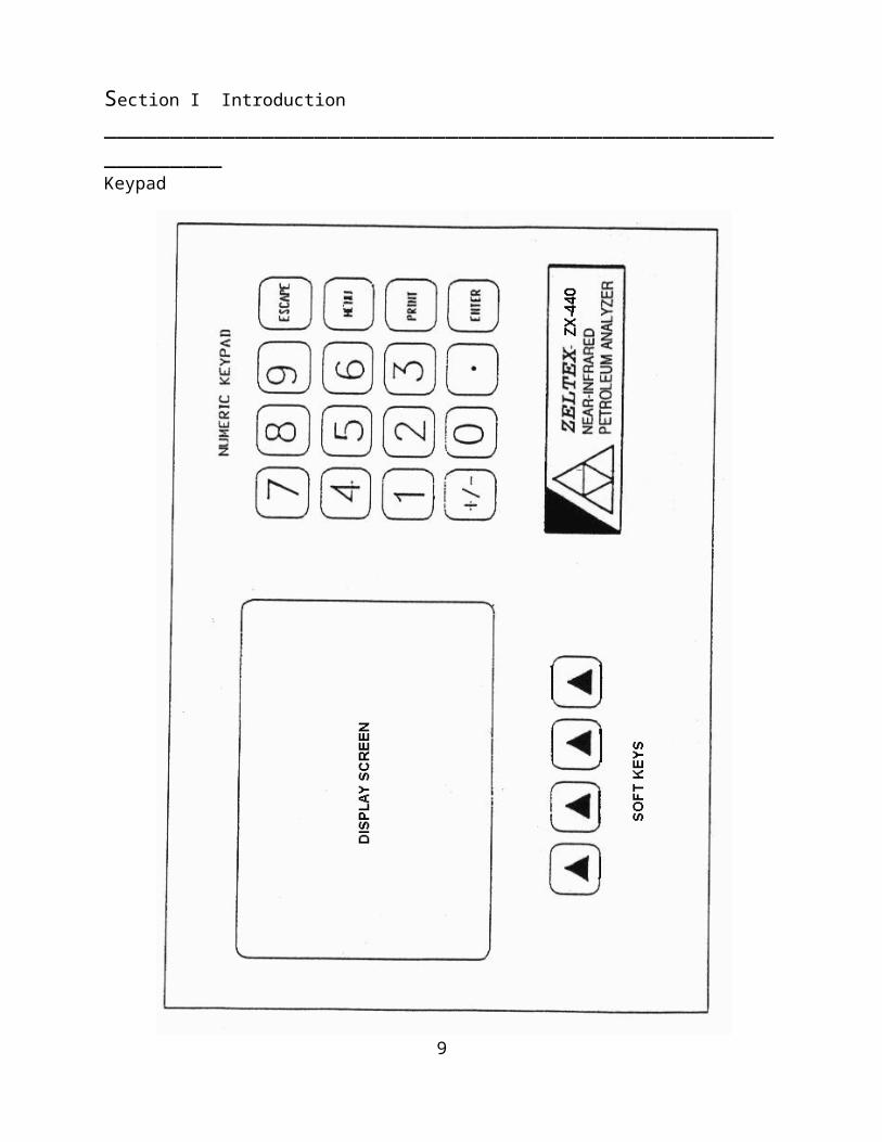
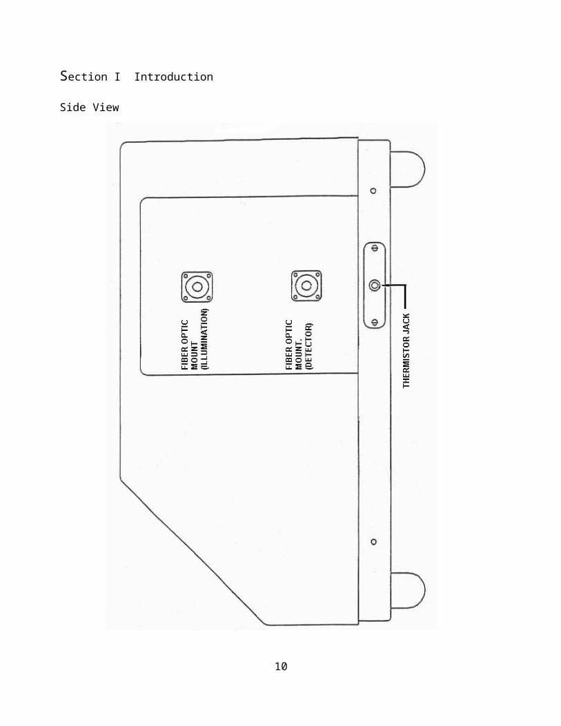
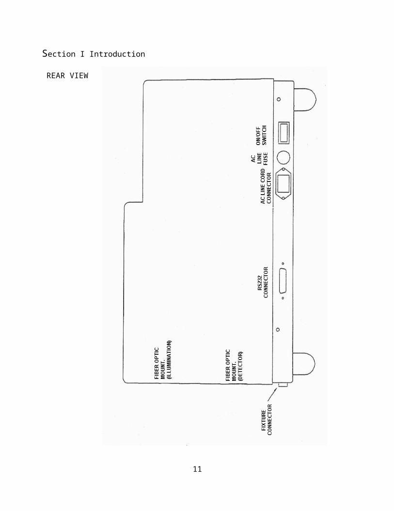
Zeltex recommends you review the following diagrams (Figures 1.2, 1.3 and 1.4) to become familiar with the ZELTEX-440 major components.
1.4 UNPACKING
1. Shipping Damage
The ZELTEX-440 is shipped in a carton designed to protect the instrument during transit. Unusually rough handling or storage outside in inclement weather could damage the carton and/or the ZELTEX-440.
Prior to unpacking, visually inspect the carton. If shipping damage has occurred, a claim should be immediately made with the shipping company (e.g. UPS).
2. Carton Contents:
o One - ZELTEX-440 Near Infrared Spectrum Composition Analyzer
o One - AC Line Cable o One - 1 Amp, Slo-Blow fuseo Four - Rolls Thermal Printer Paper (spares)o One - RS-232 Computer Cableo One - ZX-440 User's Manualo One - Calibration Number Manualo One – Calibration Software for Windows Manualo All optional accessories are listed on the Accessory sheet.

6
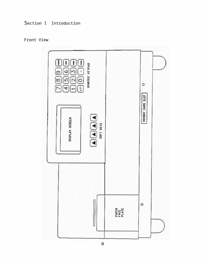
Section I Introduction
Front View
7
Section I Introduction____________________________________________________________Keypad
8
Section I Introduction
Side View
9
Section I Introduction
REAR VIEW
10
Section I Introduction
1.5 SYSTEM SET-UP
1. To install the ZELTEX-440 NIR Spectrum Composition Analyzer
o Place the ZELTEX-440 on a sturdy table
o Place the supplied line cord into the universal socket that is built into the back of the ZELTEX-440 (refer to Figure 1.3).
o The ZELTEX-440 must be properly grounded.
If the AC wall outlet has a true ground terminal then the ZELTEX-440 will be grounded. If the AC outlet is not firmly traceable to the earth, then a separate ground must be installed in order for the ZELTEX-440 to perform properly.
o Avoid electrical noise
Electrical machinery may cause "noise" on an AC power line. Although the ZELTEX-440 has been designed to be relatively immune to such electrical noise, instrumentation or generators being cycled on and off may interfere with the ZELTEX-440 performance.
In facilities with unusually poor power regulation, an external power supply regulator or line filter should be used.
2. Install the Printer Paper
The built-in Seiko printer is a thermal printer, using no ink or ribbon, but does require thermal paper.
To install the printer paper:
11
Section I Introduction
Step 1) Cut the ends of the paper off at an angle
Figure 1.5
Step 2) Remove the Paper Face Plate.
Step 3) Outside of roll is the thermally sensitive side. Begin to feed the paper (thermally sensitive side down) into the slit inside the Paper Roll Compartment.
Step 4) Turn the PAPER FEED which is on the left side of the printer to move the end of the paper through the printer.
Step 5) Pull on the end of the paper, once the paper has fed through the printer. This insures proper paper alignment to prevent jamming.
Step 6) Replace the Paper Face Plate
4. Turn On Power Switch
The Power Switch is located on the back of the instrument (refer to Figure 1.2). Once turned on, the warm-up screen is displayed.
12
Section I Introduction
5. ZELTEX-440 warm-up
All optical instruments require a warm-up period to insure that the optics and electrical systems have stabilized at operating temperature.
Once turned on, the ZELTEX-440 requires approximately twenty minutes to warm-up prior to performing measurements. Warm-up progress is indicated on the display.
13
Section I Introduction
1.6 REFERENCES
1. Conway, J.M., Norris, K.H., Bodwell, C.E., "A New Approach for the Estimation of Body Composition: Infrared Interactance." The American Journal of Clinical Nutrition 1984: 40: 1123-1130.
2. Conway, J.M., Norris, K.H., "Non-invasive Body Composition in Humans by Near-Infrared Interactance." In: Elis K.J., Yasumura S., Morgan, W.D., Ed. In Vivo Body Composition Studies. London: Institute of Physical Sciences in Medicine, 1987: 163-170.
3. Norris, K.H., "Instrumental Techniques for Measuring Quality of Agricultural Crops." In: Liebermann M. Ed. Post-Harvest Physiology and Crop Preservation. New York, NY: Plenum Publishing Corp., 1983: 471-84.
4. Norris, K.H., "Reflectance Spectroscopy." In: Whitaker, J.R., Steward, K., Modern Methods of Food Analysis. New Haven, CT: Avi Publishing Inc., 1985: 167-186.
5. Lanza, E., "Determination of Moisture, Protein, Fat, and Calories in Raw Pork and Beef by Near-Infrared Spectroscopy." Journal of Food Science 1983: 48: 471-74.
6. Rosenthal, R.D., "An Introduction to Near-Infrared Quantitative Analysis." Annual Meeting of the American Association of Cereal Chemists, 1977: 1-15.
7. Rosenthal, R.D., "Characteristics of Non-Destructive Near-Infrared Instruments for Grain and Food Products." Meeting at the Japan Food Science Institute, 1986.
8. Freifelder, D., Physical Chemistry, Applications to Biochemistry and Molecular Biology. San Francisco, W.H. Freeman and Company. Pgs. 497-98.
9. Poole, L., Borchers, M., Some Common BASIC Programs, 2nd Edition. Berkeley, CA: Adam Osborne & Associates, Inc., Pgs. 147-150.

14
SECTION IIBASIC OPERATION
2.1 TURN THE POWER SWITCH ON
The warm-up screen is displayed. The instrument requires approximately ten minutes to warm-up to ensure that the IRED's, filters and the silicon detector stabilized at an operating temperature. The ZELTEX-440 warm-up progress is indicated on the bottom of the screen. When the warm-up message on the bottom of the screen turns off, the ZELTEX-440 is ready to operate.
No ProductZELTEX 440
16 MAY 94 14:53
Warm Up \ _______
2.2 ZELTEX-440 MODES OF OPERATION
The ZELTEX-440 NIR Spectrum Composition Analyzer can be operated under two different modes:
o Test Mode after calibration is complete - Is to be used to run samples and predict the analysis of the sample from calibrations that have been previously run on the instrument.
o Calibration Mode - Calibration mode is done when trying to calibrate for a new product, or expanding the calibration for an existing product.
NOTE: In calibration mode you must have an IBM or fully IBM compatible computer available to collect the optical data and run the analysis.

15
SECTION III
FIELD SETTINGS
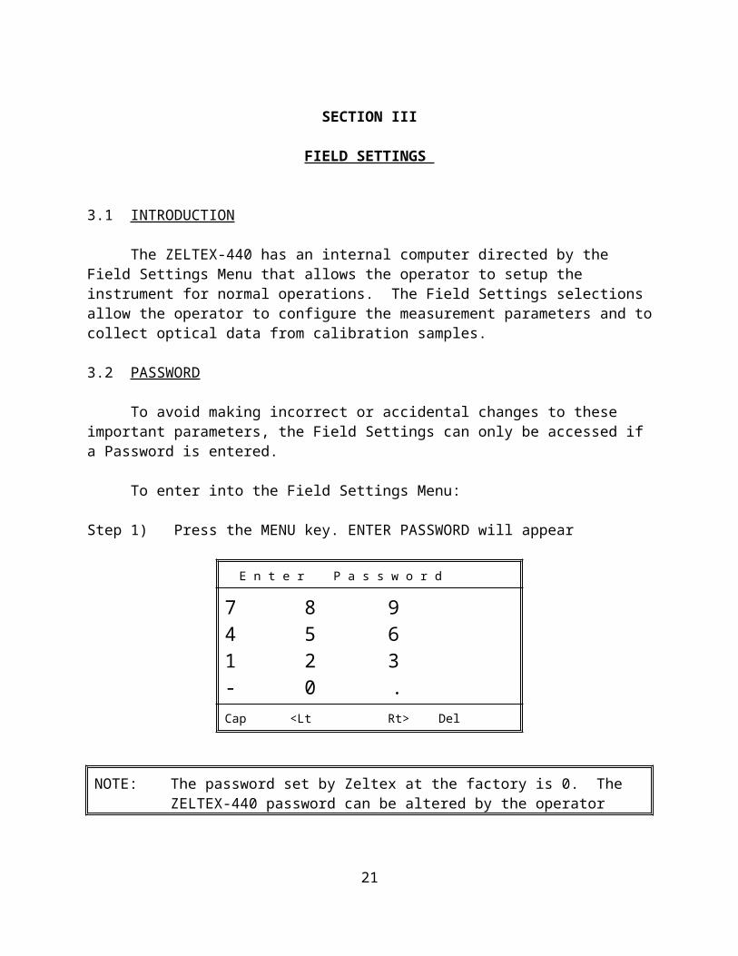
3.1 INTRODUCTION
The ZELTEX-440 has an internal computer directed by the Field Settings Menu that allows the operator to setup the instrument for normal operations. The Field Settings selections allow the operator to configure the measurement parameters and to collect optical data from calibration samples.
3.2 PASSWORD
To avoid making incorrect or accidental changes to these important parameters, the Field Settings can only be accessed if a Password is entered.
To enter into the Field Settings Menu:
Step 1) Press the MENU key. ENTER PASSWORD will appear
E n t e r P a s s w o r d
7 8 94 5 61 2 3- 0 .Cap <Lt Rt> Del
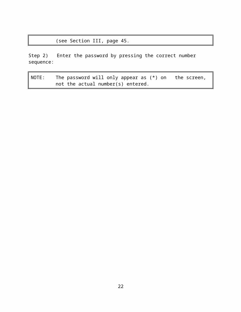
NOTE: The password set by Zeltex at the factory is 0. The ZELTEX-440 password can be altered by the operator (see Section III, page 32.
Step 2) Enter the password by pressing the correct number sequence:
NOTE: The password will only appear as (*) on the screen, not the actual number(s) entered.

16

17
Section III Field Setting _________________________________________________________________
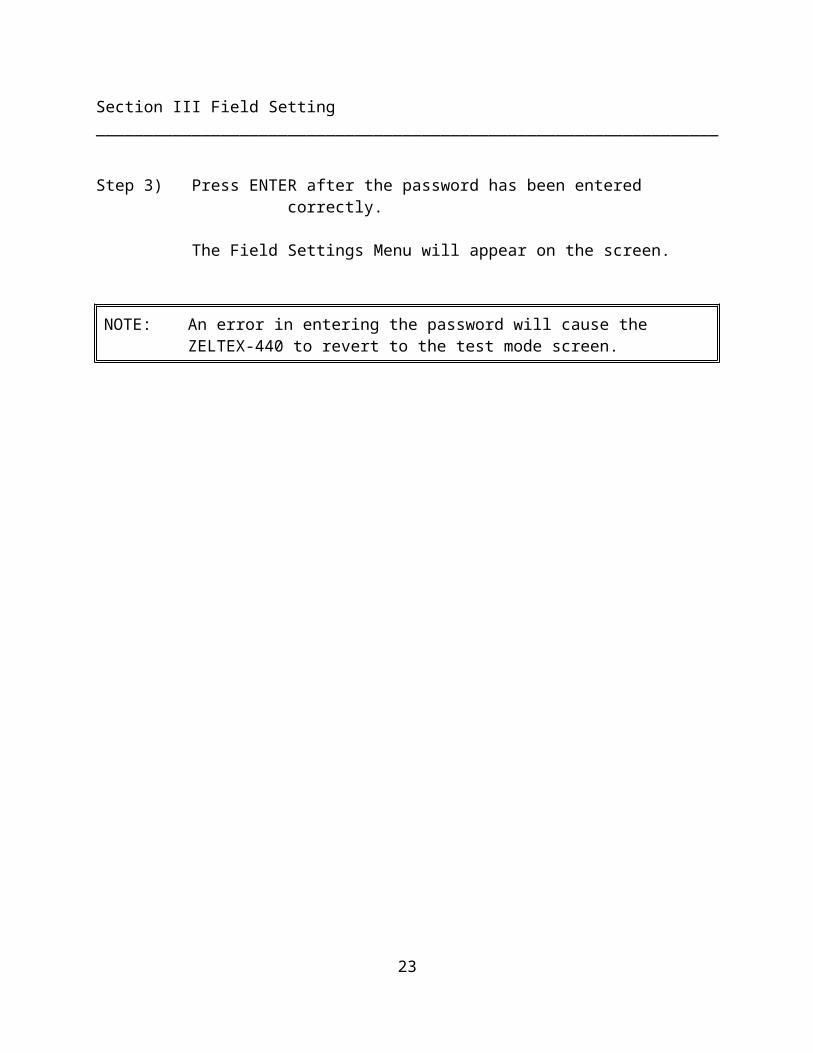
Step 3) Press ENTER after the password has been entered correctly.
The Field Settings Menu will appear on the screen.
NOTE: An error in entering the password will cause the ZELTEX-440 to revert to the test mode screen.
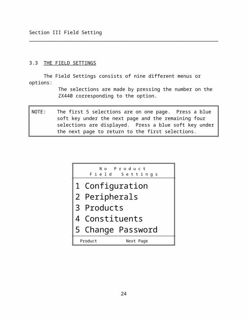
3.3 THE FIELD SETTINGS
The Field Settings consists of nine different menus or options:The selections are made by pressing the number on the ZX440 corresponding to the option.
NOTE: The first 5 selections are on one page. Press a blue soft key under the next page and the remaining four selections are displayed. Press a blue soft key under the next page to return to the first selections.
N o P r o d u c t F i e l d S e t t i n g s
1 Configuration2 Peripherals3 Products4 Constituents5 Change Password Product Next Page
18
Section III Field Setting _________________________________________________________________
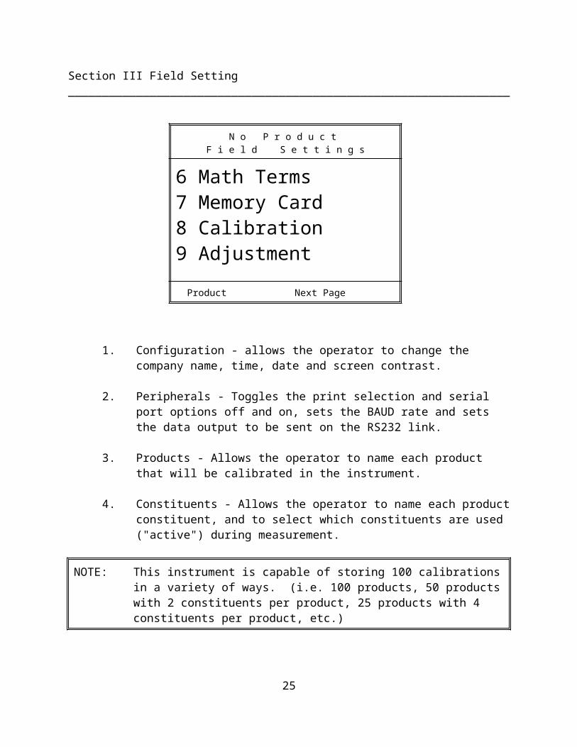
N o P r o d u c t F i e l d S e t t i n g s
6 Math Terms7 Memory Card8 Calibration9 Adjustment
Product Next Page
1. Configuration - allows the operator to change the company name, time, date and screen contrast.
2. Peripherals - Toggles the print selection and serial port options off and on, sets the BAUD rate and sets the data output to be sent on the RS232 link.
3. Products - Allows the operator to name each product that will be calibrated in the instrument.
4. Constituents - Allows the operator to name each product constituent, and to select which constituents are used ("active") during measurement.
NOTE: This instrument is capable of storing 100 calibrations in a variety of ways. (i.e. 100 products, 50 products with 2 constituents per product, 25 products with 4 constituents per product, etc.)
5. Change Password - Allows the operator to choose a new password.
6. Math Terms - Allows the operator to enter the type of mathematics, the calibration constants and/or wavelengths used in the calibration equation.
19
Section III Field Setting _________________________________________________________________
7. Mem Card - No longer included with the ZX440. It is only used to update the internal software of the ZX440.
8. Calibration - Allows the operator to determine if the calibration sample numbers will be incremented automatically, or through manual input and if the optical data will be printed following each calibration sample measurement. This function also determines if the screen plot mode is to be activated. This program should only be used for displaying optical data without the use of a computer.
9. Adjustment - Allows the operator to complete a slope and/or bias adjustment(s) to any calibration.

20
Section III Field Setting _________________________________________________________________
1. CONFIGURATION
Allows the operator to change
o Company Nameo Timeo Dateo Screen Contrast
A) Company Name - This program allows the operator to change the name of the company that appears on all printer outputs.
Press 1 from the Configuration Menu
Step 1) To enter in the company name (For example: company name is (ZELTEX)
Press 1 from the Configuration Menu - the Alpha Numeric Edit Menu will appear on the screen.
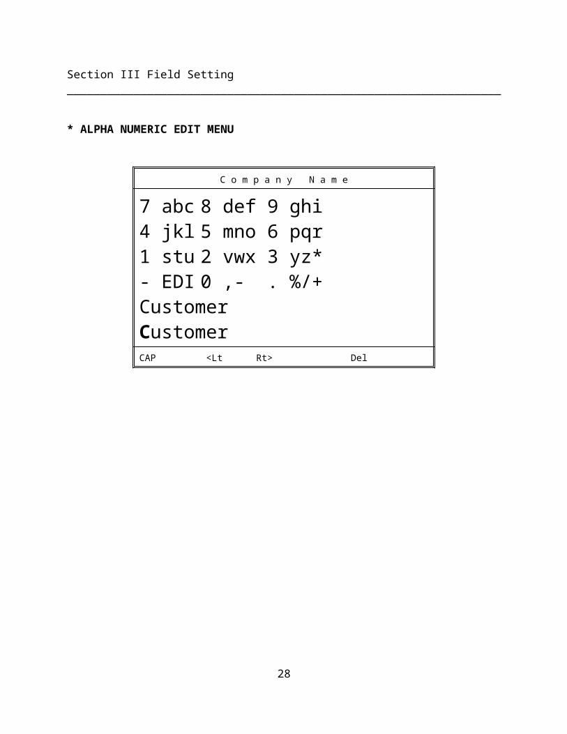
* ALPHA NUMERIC EDIT MENU
C o m p a n y N a m e
7 abc 8 def 9 ghi4 jkl 5 mno 6 pqr1 stu 2 vwx 3 yz*- EDI 0 ,- . %/+CustomerCustomerCAP <Lt Rt> Del

21
Section III Field Setting _________________________________________________________________
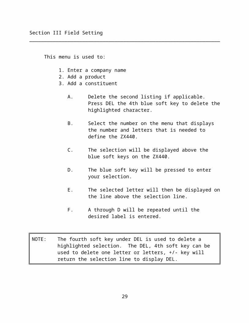
This menu is used to:
1. Enter a company name2. Add a product3. Add a constituent
A. Delete the second listing if applicable. Press DEL the 4th blue soft key to delete the highlighted character.
B. Select the number on the menu that displays the number and letters that is needed to define the ZX440.
C. The selection will be displayed above the blue soft keys on the ZX440.
D.The blue soft key will be pressed to enter your selection.
E. The selected letter will then be displayed on the line above the selection line.
F. A through D will be repeated until the desired label is entered.
NOTE: The fourth soft key under DEL is used to delete a highlighted selection. The DEL, 4th soft key can be used to delete one letter or letters, +/- key will return the selection line to display DEL.
Example:Enter a Company name - Zeltex
1. Press the DEL 4th soft key until the cursor has erased the second listing of the company name.
2. Press #3 to display 3yz*.
3. Press the third soft key directly under the letter z, <enter>.

22
Section III Field Setting _________________________________________________________________
4. Press #8 to display 8def.
5. Press the third soft key directly under the letter e, <enter>.
6. Press #4 and the fourth soft key to select l, <enter>.
7. Press #1 and the third soft key to select t, <enter>.
8. Press #8 and the third soft key to select e, <enter>.
9. Press #2 and the fourth soft key to select x, <enter>.
10. Press <enter> to store the company name - Zeltex.
NOTE: The first letter of every name will be capitalized. Subsequent letters will be lower case. Subsequent letters can be capitalized (refer to example).
Example to capitalize Zeltex:
1. Press <Lt, the second soft key to move the cursor to the left to highlight the first e.
2. Press Cap, the first soft key to capitalize.
3. Press Rt>, the third soft key to move the cursor to the right and highlight the 1.
4. Repeat 2 & 3 to capitalize the remainder of the letters
5. <enter> will store the Name.
23
Section III Field Setting _________________________________________________________________
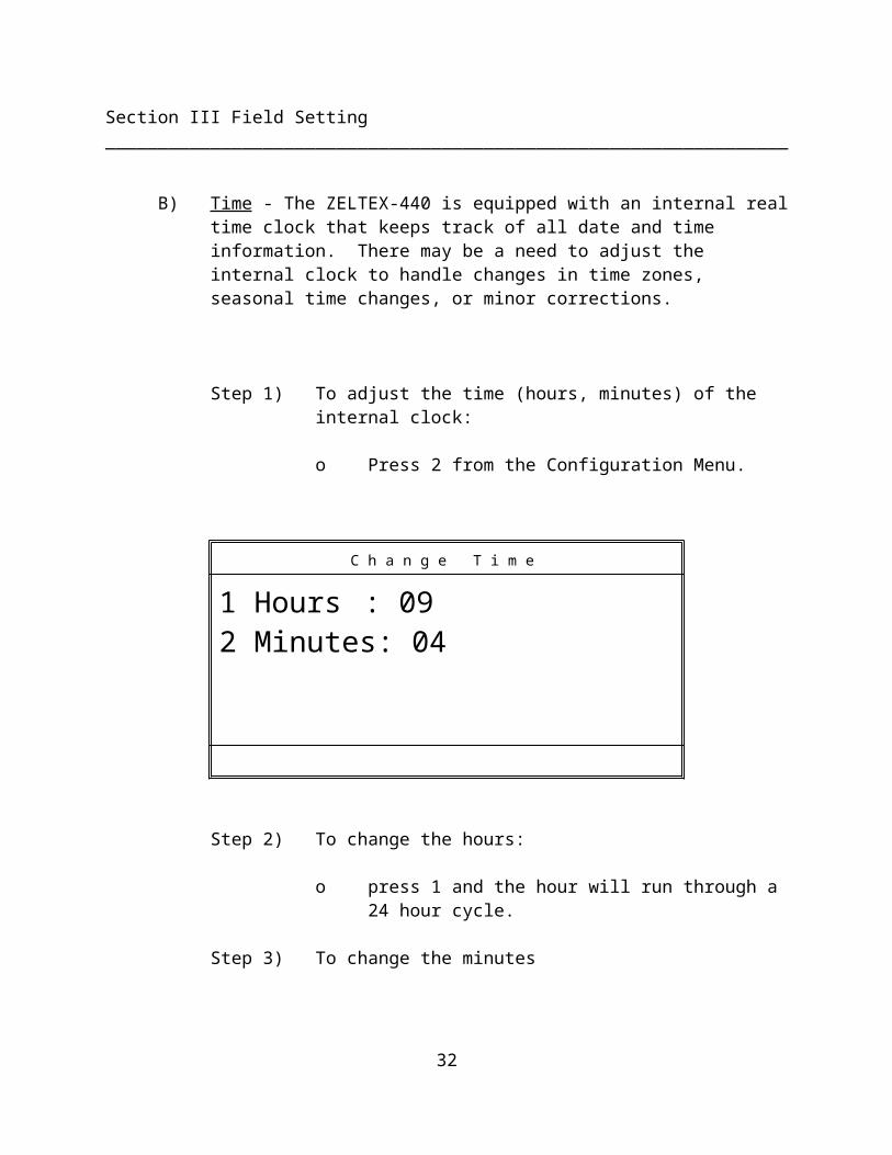
B) Time - The ZELTEX-440 is equipped with an internal real time clock that keeps track of all date and time information. There may be a need to adjust the internal clock to handle changes in time zones, seasonal time changes, or minor corrections.
Step 1) To adjust the time (hours, minutes) of the internal clock:
o Press 2 from the Configuration Menu.
C h a n g e T i m e
1 Hours : 092 Minutes: 04
Step 2) To change the hours:
o press 1 and the hour will run through a 24 hour cycle.
Step 3) To change the minutes
o press 2 and the minutes will run through a 60-minute cycle.
Step 4) When the correct time conditions have been set press ENTER.
o The changes made will be stored and the
screen will return to the Configuration Menu.
24
Section III Field Setting _________________________________________________________________
C) Date - The clock chip in the ZELTEX-440 automatically compensates for variable length months and leap years. Due to changes in time zones, however, there may be a need to adjust the internal calendar.
Step 1) To adjust the date (day, month, year) of the internal clock:
o Press 3 from the Configuration Menu
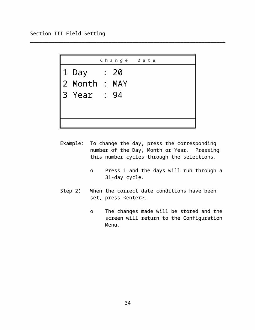
C h a n g e D a t e
1 Day : 202 Month : MAY3 Year : 94
Example: To change the day, press the corresponding number of the Day, Month or Year. Pressing this number cycles through the selections.
o Press 1 and the days will run through a 31-day cycle.
Step 2) When the correct date conditions have been set, press <enter>.
o The changes made will be stored and the screen will return to the Configuration Menu.
25
Section III Field Setting _________________________________________________________________
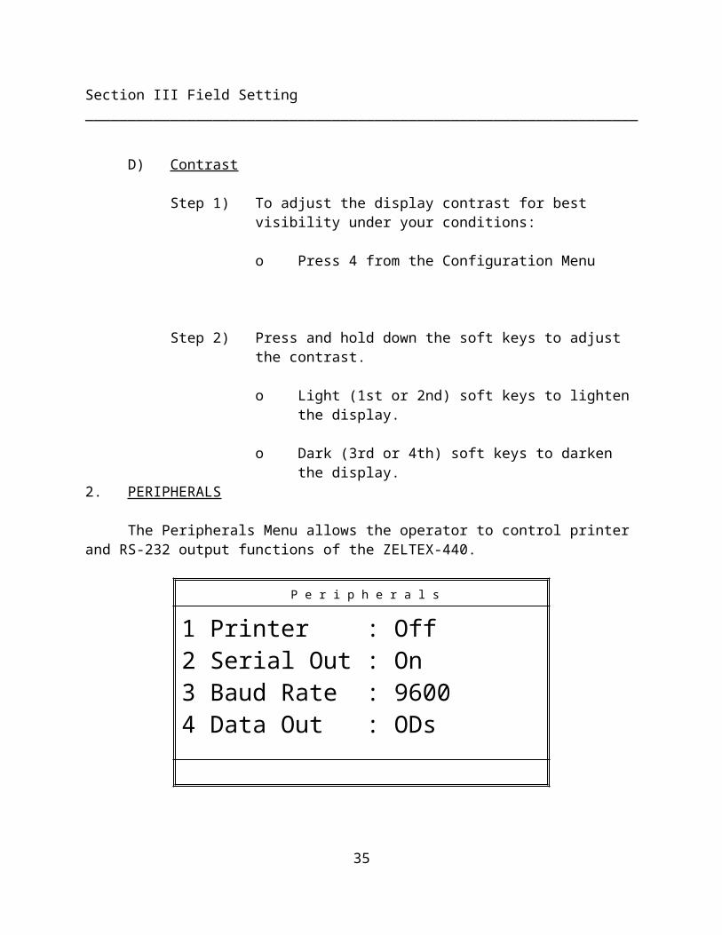
D) Contrast
Step 1) To adjust the display contrast for best visibility under your conditions:
o Press 4 from the Configuration Menu
Step 2) Press and hold down the soft keys to adjust the contrast.
o Light (1st or 2nd) soft keys to lighten the display.
o Dark (3rd or 4th) soft keys to darken the display.
2. PERIPHERALS
The Peripherals Menu allows the operator to control printer and RS-232 output functions of the ZELTEX-440.
P e r i p h e r a l s
1 Printer : Off2 Serial Out : On3 Baud Rate : 96004 Data Out : ODs
A) Printer - Allows the operator to set the ZELTEX-440 to automatically print every "Test" measurement result (in percent form) following each sample measurement.
26
Section III Field Setting _________________________________________________________________
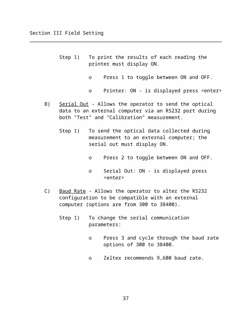
Step 1) To print the results of each reading the printer must display ON.
o Press 1 to toggle between ON and OFF.
o Printer: ON - is displayed press <enter>
B) Serial Out - Allows the operator to send the optical data to an external computer via an RS232 port during both "Test" and "Calibration" measurement.
Step 1) To send the optical data collected during measurement to an external computer; the serial out must display ON.
o Press 2 to toggle between ON and OFF.
o Serial Out: ON - is displayed press <enter>
C) Baud Rate - Allows the operator to alter the RS232 configuration to be compatible with an external computer (options are from 300 to 38400).
Step 1) To change the serial communication parameters:
o Press 3 and cycle through the baud rate options of 300 to 38400.
o Zeltex recommends 9,600 baud rate.
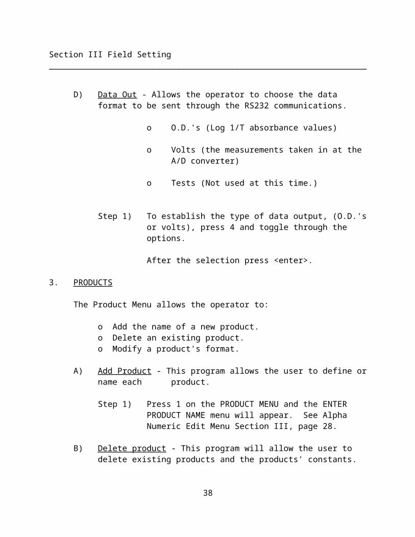
D) Data Out - Allows the operator to choose the data format to be sent through the RS232 communications.
o O.D.'s (Log 1/T absorbance values)
o Volts (the measurements taken in at the A/D converter)
o Tests (Not used at this time.)
27
Section III Field Setting _________________________________________________________________
Step 1) To establish the type of data output, (O.D.'s or volts), press 4 and toggle through the options.
After the selection press <enter>.
3. PRODUCTS
The Product Menu allows the operator to:
o Add the name of a new product.o Delete an existing product.o Modify a product's format.
A) Add Product - This program allows the user to define or name each product.
Step 1) Press 1 on the PRODUCT MENU and the ENTER PRODUCT NAME menu will appear. See Alpha Numeric Edit Menu Section III, page 20.
B) Delete product - This program will allow the user to delete existing products and the products' constants.
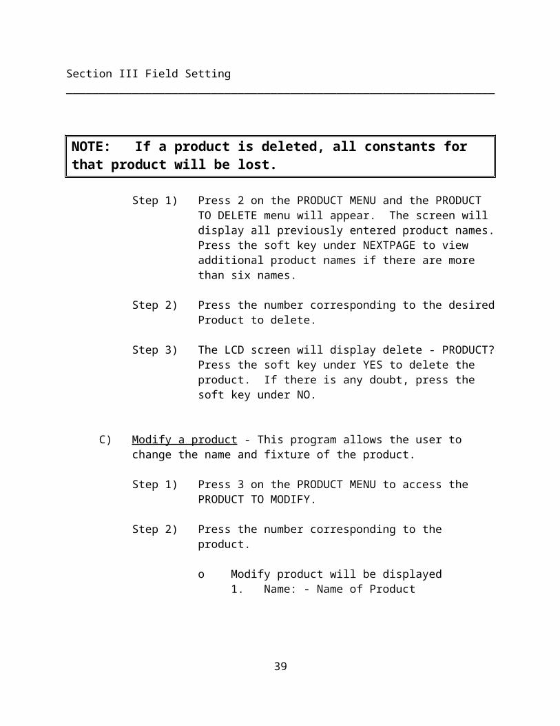
NOTE: If a product is deleted, all constants for that product will be lost.
Step 1) Press 2 on the PRODUCT MENU and the PRODUCT TO DELETE menu will appear. The screen will display all previously entered product names. Press the soft key under NEXTPAGE to view additional product names if there are more than six names.
Step 2) Press the number corresponding to the desired Product to delete.
28
Section III Field Setting _________________________________________________________________
Step 3) The LCD screen will display delete - PRODUCT? Press the soft key under YES to delete the product. If there is any doubt, press the soft key under NO.
C) Modify a product - This program allows the user to change the name and fixture of the product.
Step 1) Press 3 on the PRODUCT MENU to access the PRODUCT TO MODIFY.
Step 2) Press the number corresponding to the product.
o Modify product will be displayed1. Name: - Name of Product2. Fixt:- Descriptive word for the fixture
used in calibration. (i.e. - jar or cuvette).
Step 3) Select the number of the name or fixture to change.
Step 4) See Alpha Numeric Edit Menu, Section III, page 20.
Step 5) Press <enter> to return to the Field Settings Menu.
4. CONSTITUENTS
The Constituent Name Menu allows the operator to:
o Add the name of a constituent to be measured and evaluated.
o Edit existing constituent names.
o Delete constituent names not in use from the screen and printout
o Determine the precision (number of decimal places) used for the measurement.
29
Section III Field Setting _________________________________________________________________
NOTE: A product name must be selected before a constituent can be defined in the instrument.
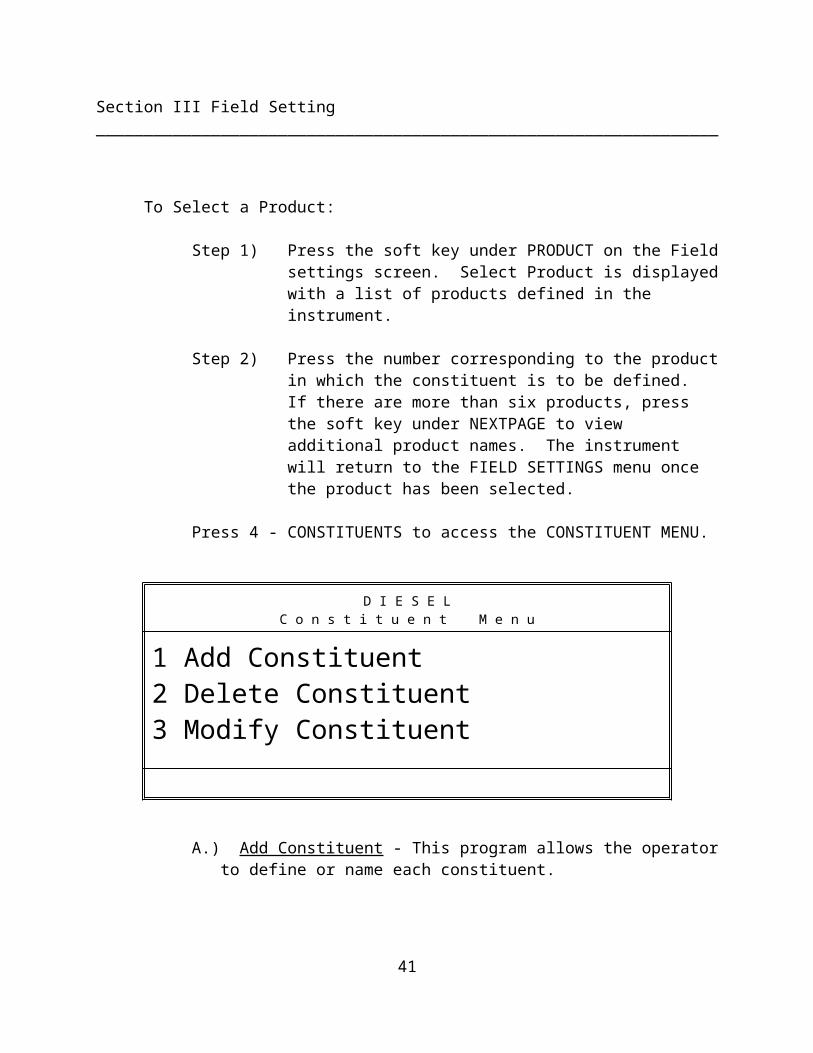
To Select a Product:
Step 1) Press the soft key under PRODUCT on the Field settings screen. Select Product is displayed with a list of products defined in the instrument.
Step 2) Press the number corresponding to the product in which the constituent is to be defined. If there are more than six products, press the soft key under NEXTPAGE to view additional product names. The instrument will return to the FIELD SETTINGS menu once the product has been selected.
Press 4 - CONSTITUENTS to access the CONSTITUENT MENU.
D I E S E LC o n s t i t u e n t M e n u
1 Add Constituent2 Delete Constituent3 Modify Constituent
A.) Add Constituent - This program allows the operator to define or name each constituent.
Step 1) Press 1 on the CONSTITUENT MENU.
Step 2) See Alpha Numeric Edit Menu, Section III, page 20.
30
Section III Field Setting _________________________________________________________________
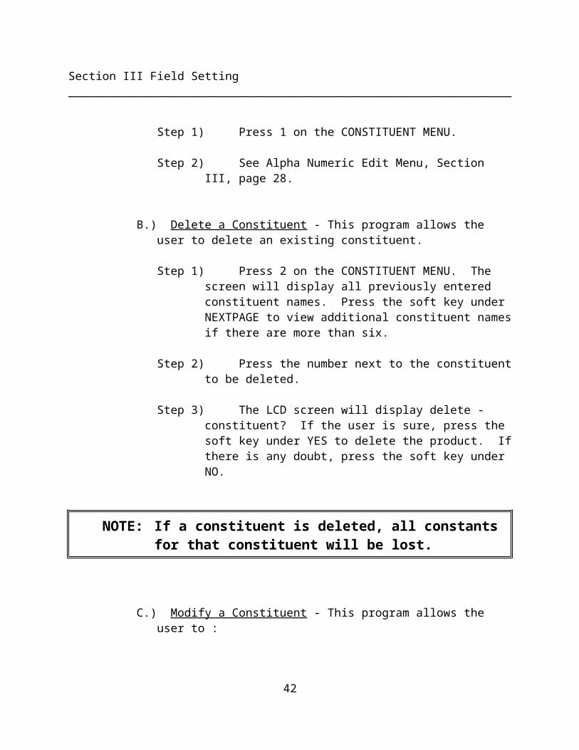
B.) Delete a Constituent - This program allows the user to delete an existing constituent.
Step 1) Press 2 on the CONSTITUENT MENU. The screen will display all previously entered constituent names. Press the soft key under NEXTPAGE to view additional constituent names if there are more than six.
Step 2) Press the number next to the constituent to be deleted.
Step 3) The LCD screen will display delete - constituent? If the user is sure, press the soft key under YES to delete the product. If there is any doubt, press the soft key under NO.
NOTE: If a constituent is deleted, all constants for that constituent will be lost.
C.) Modify a Constituent - This program allows the user to :
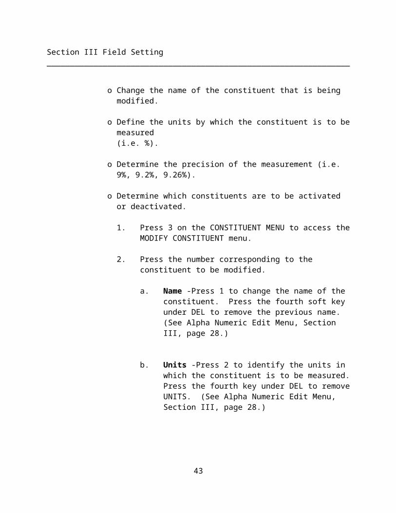
o Change the name of the constituent that is being modified.
o Define the units by which the constituent is to be measured (i.e. %).
o Determine the precision of the measurement (i.e. 9%, 9.2%, 9.26%).
o Determine which constituents are to be activated or deactivated.
31
Section III Field Setting _________________________________________________________________
1. Press 3 on the CONSTITUENT MENU to access the MODIFY CONSTITUENT menu.
2. Press the number corresponding to the constituent to be modified.
a. Name -Press 1 to change the name of the constituent. Press the fourth soft key under DEL to remove the previous name. (See Alpha Numeric Edit Menu, Section III, page 20.)
b. Units -Press 2 to identify the units in which the constituent is to be measured. Press the fourth key under DEL to remove UNITS. (See Alpha Numeric Edit Menu, Section III, page 20.)
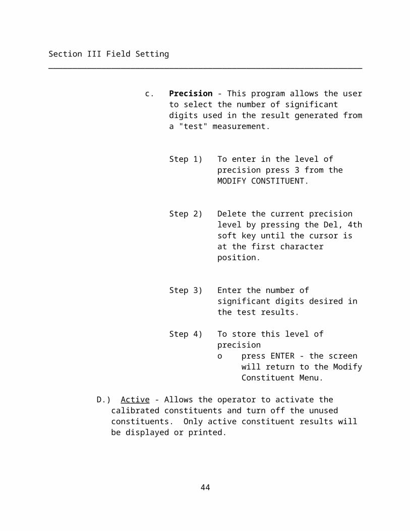
c. Precision - This program allows the user to select the number of significant digits used in the result generated from a "test" measurement.
Step 1) To enter in the level of precision press 3 from the MODIFY CONSTITUENT.
Step 2) Delete the current precision level by pressing the Del, 4th soft key until the cursor is at the first character position.
Step 3) Enter the number of significant digits desired in the test results.
Step 4) To store this level of precision

32
Section III Field Setting _________________________________________________________________
o press ENTER - the screen will return to the Modify Constituent Menu.
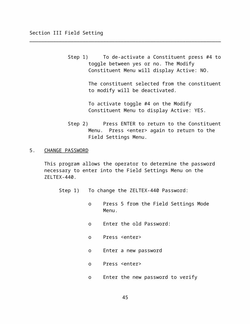
D.) Active - Allows the operator to activate the calibrated constituents and turn off the unused constituents. Only active constituent results will be displayed or printed.
Step 1) To de-activate a Constituent press #4 to toggle between yes or no. The Modify Constituent Menu will display Active: NO.
The constituent selected from the constituent to modify will be deactivated.
To activate toggle #4 on the Modify Constituent Menu to display Active: YES.
Step 2) Press ENTER to return to the Constituent Menu. Press <enter> again to return to the Field Settings Menu.
5. CHANGE PASSWORD
This program allows the operator to determine the password necessary to enter into the Field Settings Menu on the ZELTEX-440.
Step 1) To change the ZELTEX-440 Password:
o Press 5 from the Field Settings Mode Menu.
o Enter the old Password:
o Press <enter>
o Enter a new password
o Press <enter>
o Enter the new password to verify
33
Section III Field Setting _________________________________________________________________
Press <enter> This returns the user to the Field Setting Menu.
NOTE: Record the new password and place it in your files.
6. MATH TERMS
The Math Terms allows the operator to select different mathematic models to be used in the optimum algorithm for each constituent. The corresponding optimum wavelengths and calibration constants can also be entered or changed using the Math Menu program.
NOTE: The product must be selected prior to using any of the programs listed in this menu.
Press 6 - Math Terms
1) Math - There are five mathematical model options available in the ZELTEX-440 software.
o Normal MLR - for entering constants from Multiple Linear Regression, Partial Least Squares, or Inverse Least Squares.
o 1st Deriv - the first derivative of the optical data.
o 2nd Deriv - the second derivative of the optical data.
o 1D Ratio - the first division math where the ratios of the first derivatives are taken at specific wavelengths.
o 2D Ratio - the second division math where the ratios of the second derivatives are taken at specific wavelengths.
NOTE: Zeltex recommends Normal MLR for the math type selection.
34
Section III Field Setting _________________________________________________________________
Contact Zeltex if another math type is necessary.
35
Section III Field Setting _________________________________________________________________
The constituent and term are displayed at the top of the screen.
Step 1) To select a different constituent:
o Press the 1st or 2nd soft keys +C and -C and toggle between the available active constituents.
Step 2) To select a different term:
o Press the 3rd or 4th soft keys below +T and -T and step between term 1 and 37, with additional terms of A (sample temperature), B (ambient temperature and 0 (offset adjustment).
o The soft key below +T steps the terms forward and the soft key -T steps the terms backward.
1) Select the proper mathematic model:
NOTE: Term (TM) - 1 Math: will be offset.
o Press +T, 3rd soft key to display term 1.
o Press 1 from the math menu and the models will step through the choices of Normal MLR, 1st Deriv, 2nd Deriv, 1D ratio and 2D ratio.
o Math choices must be the same for all terms. (1-37).
o Zeltex recommends Normal MLR.
2) K: - This program allows the operator to enter the calibration constants for each term in an algorithm for a specific
36
Section III Field Setting _________________________________________________________________
constituent, K Offset, K1 through K37 and K Sample temperature.
Step 1) To enter in the K value for the selected term:
o Press 2 from the Math Menu.
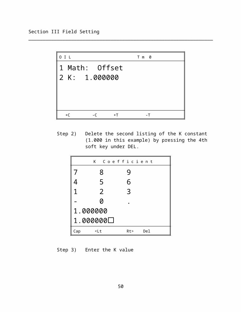
O I L T m 0
1 Math: Offset2 K: 1.000000
+C -C +T -T
Step 2) Delete the second listing of the K constant (1.000 in this example) by pressing the 4th soft key under DEL.
K C o e f f i c i e n t
7 8 94 5 61 2 3- 0 .1.0000001.000000Cap <Lt Rt> Del
Step 3) Enter the K value
37
Section III Field Setting _________________________________________________________________
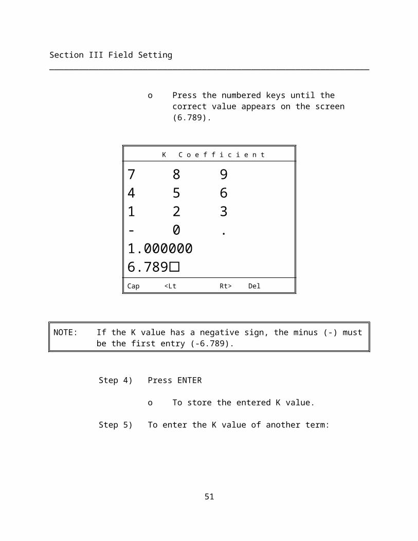
o Press the numbered keys until the correct value appears on the screen (6.789).
K C o e f f i c i e n t
7 8 94 5 61 2 3- 0 .1.0000006.789Cap <Lt Rt> Del
NOTE: If the K value has a negative sign, the minus (-) must be the first entry (-6.789).
Step 4) Press ENTER
o To store the entered K value.
Step 5) To enter the K value of another term:
o Toggle the Term (3rd or 4th) soft key below +T and -T until the term to be adjusted appears on the screen.
Step 6) Repeat Steps 1 - 4 for the remaining terms in the calibration equation.
38
Section III Field Setting _________________________________________________________________
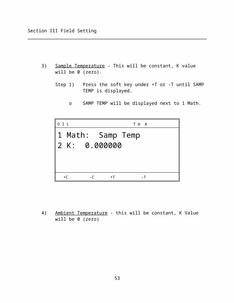
3) Sample Temperature - This will be constant, K value will be 0 (zero).
Step 1) Press the soft key under +T or -T until SAMP TEMP is displayed.
o SAMP TEMP will be displayed next to 1 Math.
O I L T m A
1 Math: Samp Temp2 K: 0.000000
+C -C +T -T
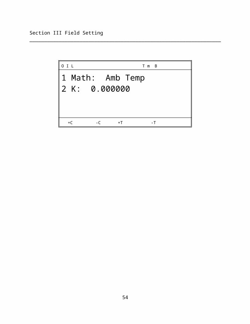
4) Ambient Temperature - this will be constant, K Value will be 0 (zero)
O I L T m B
1 Math: Amb Temp2 K: 0.000000
+C -C +T -T
39
Section III Field Setting _________________________________________________________________
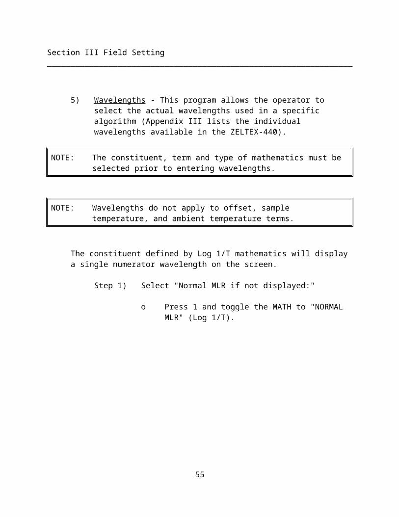
5) Wavelengths - This program allows the operator to select the actual wavelengths used in a specific algorithm (Appendix III lists the individual wavelengths available in the ZELTEX-440).
NOTE: The constituent, term and type of mathematics must be selected prior to entering wavelengths.
NOTE: Wavelengths do not apply to offset, sample temperature, and ambient temperature terms.
The constituent defined by Log 1/T mathematics will display a single numerator wavelength on the screen.
Step 1) Select "Normal MLR if not displayed:"
o Press 1 and toggle the MATH to "NORMAL MLR" (Log 1/T).
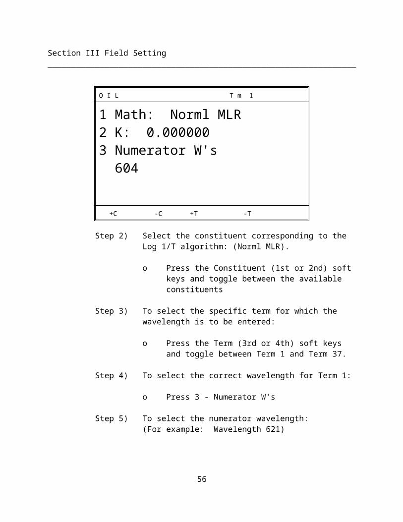
O I L T m 1
1 Math: Norml MLR2 K: 0.0000003 Numerator W's 604
+C -C +T -T
Step 2) Select the constituent corresponding to the Log 1/T algorithm: (Norml MLR).
40
Section III Field Setting _________________________________________________________________
o Press the Constituent (1st or 2nd) soft keys and toggle between the available constituents
Step 3) To select the specific term for which the wavelength is to be entered:
o Press the Term (3rd or 4th) soft keys and toggle between Term 1 and Term 37.
Step 4) To select the correct wavelength for Term 1:
o Press 3 - Numerator W's
Step 5) To select the numerator wavelength:(For example: Wavelength 621)
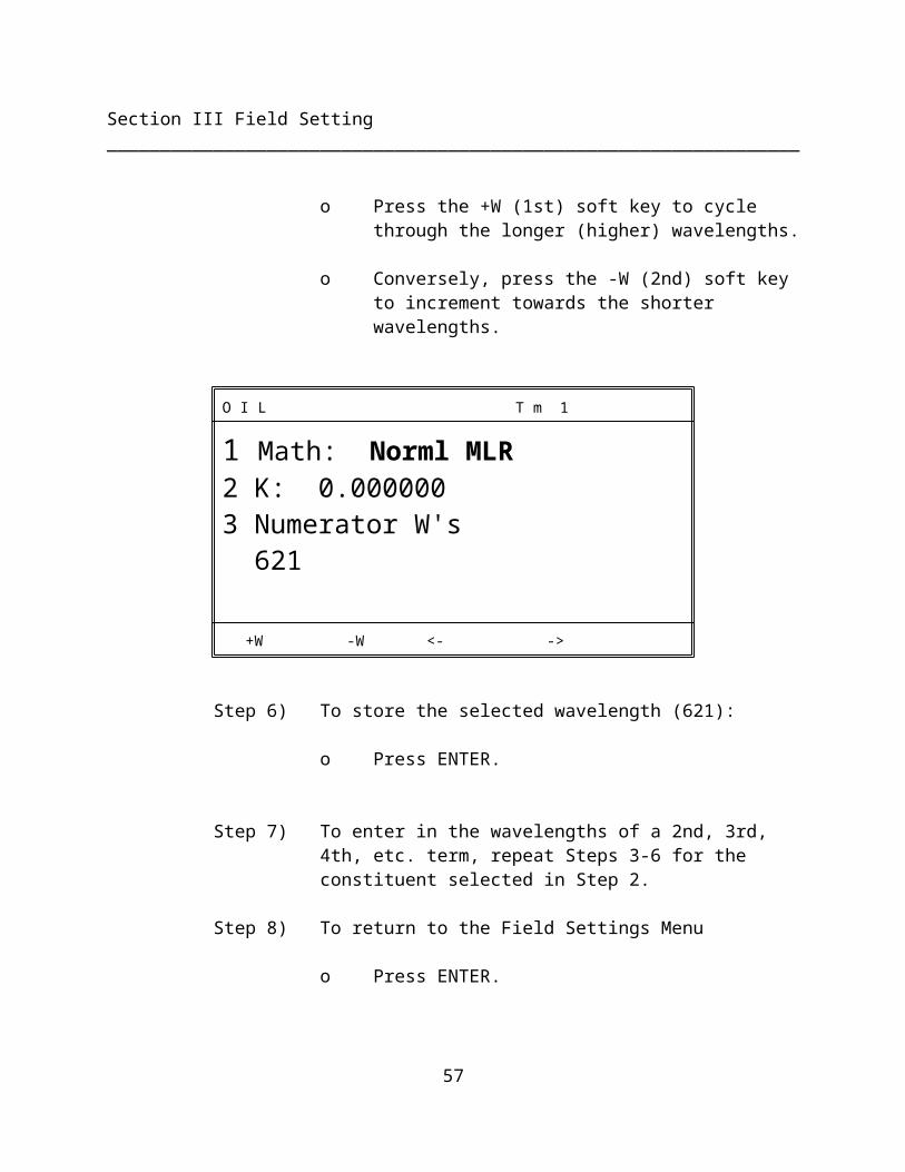
o Press the +W (1st) soft key to cycle through the longer (higher) wavelengths.
o Conversely, press the -W (2nd) soft key to increment towards the shorter wavelengths.
O I L T m 1
1 Math: Norml MLR2 K: 0.0000003 Numerator W's 621
+W -W <- ->
Step 6) To store the selected wavelength (621):
o Press ENTER.
41
Section III Field Setting _________________________________________________________________
Step 7) To enter in the wavelengths of a 2nd, 3rd, 4th, etc. term, repeat Steps 3-6 for the constituent selected in Step 2.
Step 8) To return to the Field Settings Menu
o Press ENTER.
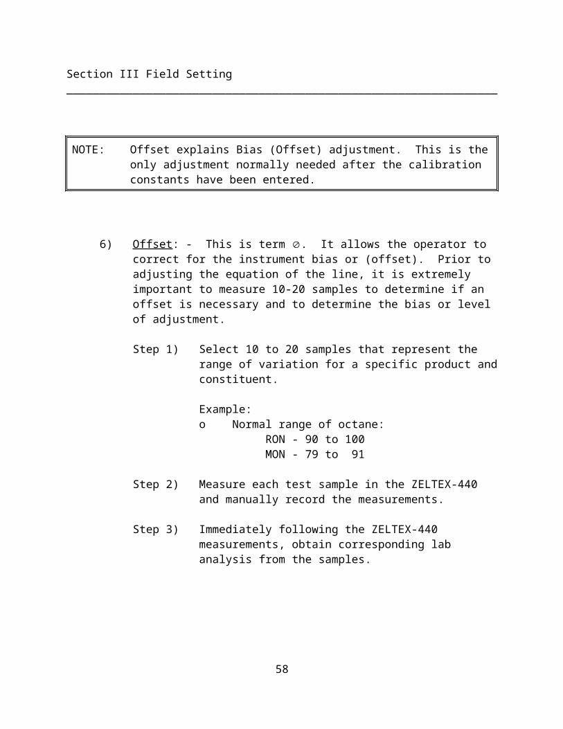
NOTE: Offset explains Bias (Offset) adjustment. This is the only adjustment normally needed after the calibration constants have been entered.
6) Offset: - This is term . It allows the operator to correct for the instrument bias or (offset). Prior to adjusting the equation of the line, it is extremely important to measure 10-20 samples to determine if an offset is necessary and to determine the bias or level of adjustment.
Step 1) Select 10 to 20 samples that represent the range of variation for a specific product and constituent.
Example:o Normal range of octane:
RON - 90 to 100MON - 79 to 91
Step 2) Measure each test sample in the ZELTEX-440 and manually record the measurements.
Step 3) Immediately following the ZELTEX-440 measurements, obtain corresponding lab analysis from the samples.

42
Section III Field Setting _________________________________________________________________
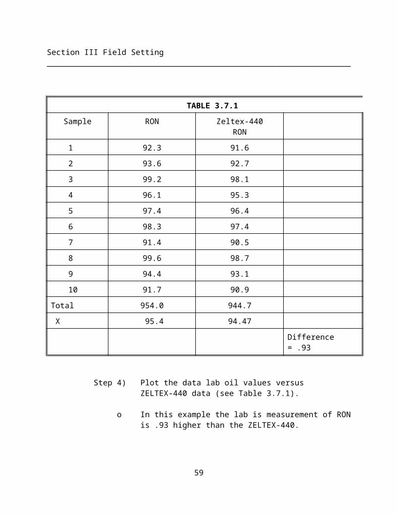
TABLE 3.7.1Sample RON Zeltex-440
RON1 92.3 91.62 93.6 92.73 99.2 98.14 96.1 95.35 97.4 96.46 98.3 97.47 91.4 90.58 99.6 98.79 94.4 93.110 91.7 90.9
Total 954.0 944.7 X 95.4 94.47
Difference = .93
Step 4) Plot the data lab oil values versus ZELTEX-440 data (see Table 3.7.1).
o In this example the lab is measurement of RON is .93 higher than the ZELTEX-440.
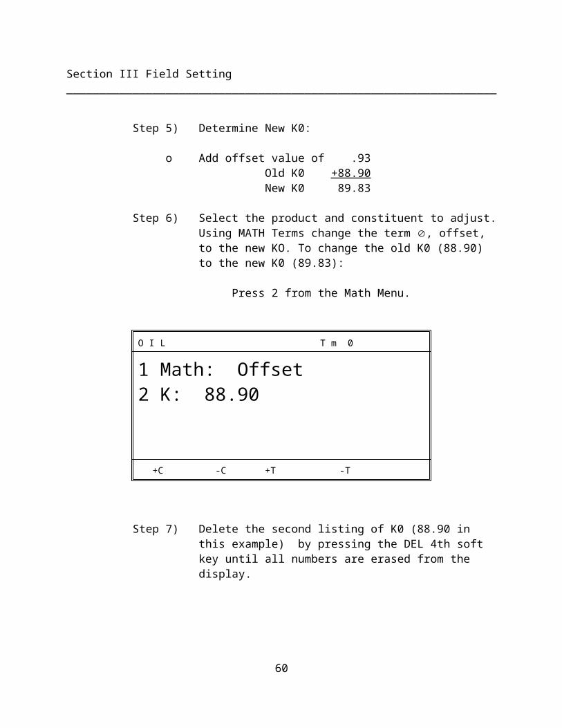
Step 5) Determine New K0:
o Add offset value of .93Old K0 +88.90New K0 89.83
43
Section III Field Setting _________________________________________________________________
Step 6) Select the product and constituent to adjust. Using MATH Terms change the term , offset, to the new KO. To change the old K0 (88.90) to the new K0 (89.83):
Press 2 from the Math Menu.
O I L T m 0
1 Math: Offset2 K: 88.90
+C -C +T -T
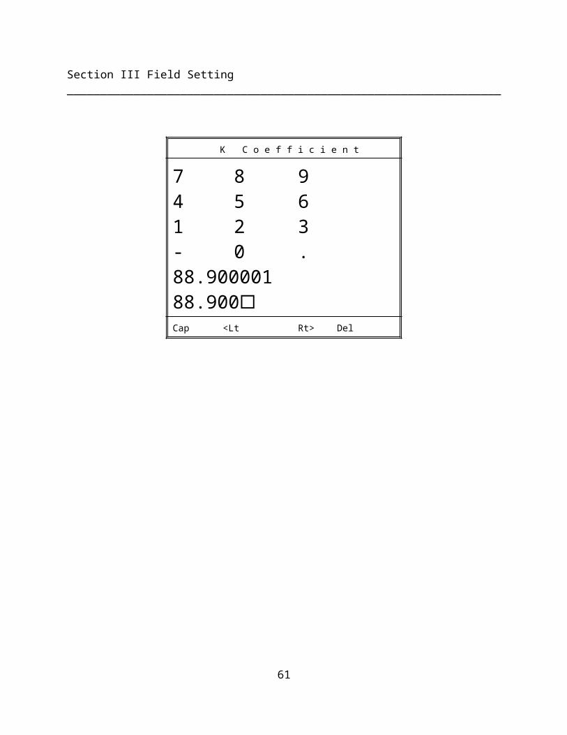
Step 7) Delete the second listing of K0 (88.90 in this example) by pressing the DEL 4th soft key until all numbers are erased from the display.
K C o e f f i c i e n t
7 8 94 5 61 2 3- 0 .88.90000188.900Cap <Lt Rt> Del
44
Section III Field Setting _________________________________________________________________
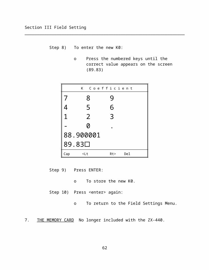
Step 8) To enter the new K0:
o Press the numbered keys until the correct value appears on the screen (89.83)
K C o e f f i c i e n t
7 8 94 5 61 2 3- 0 .88.90000189.83Cap <Lt Rt> Del
Step 9) Press ENTER:
o To store the new K0.
Step 10) Press <enter> again:
o To return to the Field Settings Menu.
7. THE MEMORY CARD No longer included with the ZX-440.
o The Memory Card allows the user to update the ZELTEX-440 internal software without returning the instrument for a service call.
o Contact Zeltex before using.
45
Section III Field Setting _________________________________________________________________
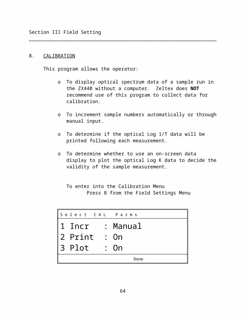
8. CALIBRATION
This program allows the operator:
o To display optical spectrum data of a sample run in the ZX440 without a computer. Zeltex does NOT recommend use of this program to collect data for calibration.
o To increment sample numbers automatically or through manual input.
o To determine if the optical Log 1/T data will be printed following each measurement.
o To determine whether to use an on-screen data display to plot the optical Log K data to decide the validity of the sample measurement.
To enter into the Calibration MenuPress 8 from the Field Settings Menu
S e l e c t C A L P a r m s
1 Incr : Manual2 Print : On3 Plot : On
Done
1) Increments Selection: - Press #1 to toggle the Manual or Auto Selection
o Manual - allows the operator to input sample ID numbers from 1 to 9999.
46
Section III Field Setting _________________________________________________________________
o Auto - the ZELTEX-440 automatically increments the sample ID numbers by 1.
2) Print Selection: Press #2 to toggle off or on the option for printing the optical data following each measurement.
3) Plot: Press #3 to toggle off or on the option to display the optical data on the screen of the ZX440.
Plot allows the operator to view a graph of the optical Log K data prior to printing it out. Plotting the optical data also allows the user to reject sample measurements that are obviously bad. Press the blue Print key on the ZX440 to print the graph.
To begin a sample measurement sequence:
o Press the 3rd or 4th soft key under Done after Cal Parameters have be selected.
o Press Cal (3rd or 4th) soft keys.
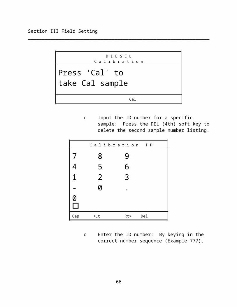
D I E S E LC a l i b r a t i o n
Press 'Cal' to take Cal sample
Cal
o Input the ID number for a specific sample: Press the DEL (4th) soft key to delete the second sample number listing.
47
Section III Field Setting _________________________________________________________________
C a l i b r a t i o n I D
7 8 94 5 61 2 3- 0 .0Cap <Lt Rt> Del
o Enter the ID number: By keying in the correct number sequence (Example 777).
C a l i b r a t i o n I D
7 8 94 5 61 2 3- 0 .777777Cap <Lt Rt> Del
o To store the ID number: Press ENTER and the screen will read:
Prepare to take Standard
48
Section III Field Setting _________________________________________________________________
o Attach the light cover and/or standard to the fixture. Press Done (3rd or 4th soft keys) when ready to take standard.
o The ZELTEX-440 will automatically make a standard reading "STANDARD...." will flash on the screen.
o Remove the light cover/standard and place sample to be measured in the light path when INSERT SAMPLE message appears.
o Press Done (3rd or 4th) soft keys and the ZELTEX-440 will begin its "SAMPLING...." measurement sequence.
o When screen reads "CALCULATING....", the sample may be removed
o If the plot function is activated, the screen will display a plot of the optical log 1/T data.
o The operator can select if the calibration data is valid. If not, the operator can read that sample again.
o Upon completion of the measurement sequence the screen will read CAL SAMPLE 00777 completed.
o Press the PRINT key for a screen print of the plot.
NOTE: It is recommended that the number and any other pertinent demographic and/or constituent data be recorded on a Log sheet.
9. ADJUSTMENT
49
Section III Field Setting _________________________________________________________________
This program allows the operator to:
o Simultaneously perform a slope and/or bias adjustment to any calibration.
The following steps are for manually entering the slope and bias adjustment from the factory calculated values:
NOTE: Product must be selected prior to using this program.
Step 1) If the customer has had Zeltex personnel calculate the slope and bias adjustment, the adjustment(s) may be entered by pressing 9 on the FIELD SETTING menu.
D I E S E LO I L P a r m s
1 Slope: 1.0002 Bias: 0.000
Constit Adjust
Step 2) Select the constituent to adjust by pressing soft key 1 or 2 under Constit to toggle the selection of the active constituents.
Step 3) Press 1 to change the slope. Delete the previous slope and press the numbers on the keypad to enter the new value. Press ENTER to accept the new value.
50
Section III Field Setting _________________________________________________________________
Step 4) Press 2 to change the bias. Delete the previous bias and press the numbers on the keypad to enter the new value. Press ENTER to accept the new value.
Step 5) If there is more than one constituent per product that has adjustments to be made, press the soft key under CONSTIT to select another constituent.
Step 6) Repeat step 2 through step 4 until all the necessary adjustments are completed.
Slope and bias adjustments - CONTACT ZELTEX BEFORE ADJUSTING CALIBRATION
1) Manual - Allows the operator to input lab and sample constituent analysis and automatically adjust slope and bias.
2) Automatic - Allows the operator to manually input the lab analysis. Constants are previously entered into the instrument. Samples are read and the actual percent of a constituent is measured. Adjustments are completed by calculating the differences between the two analysis.
NOTE: Constants must be previously stored in the instrument before adjustments can be calculated in the automatic mode.
NOTE: Zeltex recommends using manual adjustment mode.
NOTE: Ten to twenty samples must be previously read by the ZELTEX-440. The lab analysis and instrument percentages are to be recorded. Select the constituent to which the adjustments
51
Section III Field Setting _________________________________________________________________
need to be made.
Steps for slope and bias adjustment using the manual mode
Step 1) Press the soft key under ADJUST and the following screen will appear:
O I L A d j u s t
1 Smp Mode: Manual2 Review Test Pts3 Add Test Pts
Done
NOTE: The user can press 2 REVIEW TEST PTS at any time during the entry process to review and/or correct values that have been previously entered.
Step 2) Press 1 and toggle from AUTO to MANUAL sample mode.
Step 3) Press 3 ADD TEST PT.
Step 4) Enter the laboratory analysis for sample number 1. Press ENTER to accept this value.
52
Section III Field Setting _________________________________________________________________
Step 5) Enter the instrument analysis for the same sample. Press ENTER to accept this value.
Step 6) The user will be asked to ACCEPT or DISCARD this value. Press the soft key under the acceptable term.
Step 7) Repeat step 3 through step 6 for the remaining samples.
NOTE: The instrument will automatically display, after the third entry, the new slope, correlation and standard deviation for each sample added. The user is asked to ACCEPT or DISCARD these values.
Step 8) Press the soft key under DONE after all accuracy sample data has been entered into the instrument.
NOTE: The screen will display the old slope, the old bias, the new slope and the new bias.
Step 9) The user is asked to ACCEPT or DISCARD the new values.
A. Accepting the new slope or bias values will adjust the ZELTEX-440 calibration.
B. Discarding the new values will take the user back to the following screen and reject the adjustment.
53
Section III Field Setting _________________________________________________________________
O I L A d j u s t
1 Smp Mode: Manual2 Review Test Pts3 Add Test Pts
Done
The user can press ENTER and return to the FIELD SETTINGS, or press the soft key under ADJUST and redo the adjustment calculations.
54
SECTION IV
TEST MODE
4.1 INTRODUCTION
The Test Mode allows the operator to make direct sample measurements of selected product constituents for which calibration equations have been previously stored in the ZELTEX-440.
4.2 SAMPLE "TEST" MEASUREMENT
This is the mode for measurement of a sample after calibration after calibration has been performed and the algorithm generated and stored in the ZX440.
To make a measurement on the ZX440 use the following instructions:
Step 1) On the top of the screen will be displayed the current product and fixture. If this product is not the product you want to measure press the PRODUCT key (1st and 2nd soft keys) and then the number corresponding to the correct product.
Step 2) Once the correct product is displayed on the screen press the TEST key (3rd or 4th soft key). The screen will then read:
ZELTEX 440
PREPARE TO TAKE STANDARD
DONE
55
NOTE: All external light must be blocked.
Step 3) Cover the chamber and Press DONE , 3rd or 4th soft key. The ZELTEX-440 will automatically make a standard reading, "STANDARD...." will flash on the screen.
ZELTEX 440
INSERT SAMPLE OFPRODUCT NAME
1 of 2
DONE
Step 4) Press the Done (3rd or 4th) soft keys and the ZELTEX-440 will begin its "SAMPLING...." measurement sequence.
ZELTEX 440
INSERT SAMPLE OFPRODUCT NAME
2 of 2
DONE
56
Step 5) Repeat step 4 through 6 for the number of readings the user has selected for the setup of the ZX440. The jar sample should be rotated 180o and realigned between readings.
Step 6) When the screen reads "CALCULATING...." the sample can be removed from the chamber.
Step 7) The analysis of the product will appear on the screen and/or be printed when the measurement sequence has been completed.
PRODUCT NAME 00001
CETANE42.8
Next Page Test
NOTE: If the calibration equations for more than one parameter is stored (i.e., "Active" - refer to Section III, page 32 ), press the constituent (1st or 2nd) soft keys to toggle through the Active Constituent values. If the printer function is ON, the results for all "Active" constituents will be printed.
Step 8) To make the next measurement
o Press ENTER and repeat Steps 1-7.
57
SECTION V
TROUBLE-SHOOTING
TROUBLE-SHOOTING --- GENERAL NOTES:
The general approach to trouble-shooting is a process of elimination. One must isolate the problem to a specific area, then check the simplest and most likely things first. For example, if the unit won't start-up, it's usually a power problem. If the unit works fine from the keypad, but not remotely, then it's a problem with the RS-232 link. In this situation, check the cable, configuration of instrument and computer, the external computer itself, and external software.
Such a logical approach will quickly solve most problems. The following chart provides suggested remedies for common problems. When problems persist, or any other type of support is needed, CALL THE FACTORY FOR ASSISTANCE (1-800-732-1950 or 301-791-7080)
Please note that authorized user trouble-shooting is limited to external problems--fuse, connectors, memory cards, etc. Any further service must be referred to the factory or factory authorized personnel.
WARNING #1 - Lethal voltages are present inside the base unit.
WARNING #2 - Opening the case of the ZX-440 may change characteristics of the instrument to the point where any data stored for a calibration maybe rendered useless. Such service should be undertaken only by factory authorized personnel.
UNAUTHORIZED OPENING OF THE CASE OF THE ZX-440 WILL VOID YOUR WARRANTY.
58
Trouble-Shooting______________________________________________________________________
Problem #1:
Instrument won't turn on (no beep or display activity -- appears dead).
Possible Cause #1: Power not getting to instrument.
Remedy: Make sure instrument is plugged in and connections are tight.
Remedy: Make sure power outlet is functional by plugging in some other electrical instrument (e.g. a lamp).
Possible Cause #2: Blown fuse.
Remedy: Unplug instrument and check fuse. If the fuse is blown replace it with the same type and rating (1 amp Slow Blow)
Possible Cause #3: Internal failure.
Remedy: *** Contact factory ***
Problem #2:
Instrument turns on, but display does not come up to initial screen.
Possible Cause #1: Program failure.
Remedy: *** Contact factory ***
Possible Cause #2: Internal Failure.
Remedy: *** Contact factory ***
59
Trouble-Shooting______________________________________________________________________
Problem #3:Instrument seems to boot up OK, but never seems to complete the warm-up period.
Possible Cause #1: Failure of heater or sensing circuit.
Remedy: *** Contact factory ***
Problem 4#:Instrument doesn't seem to communicate with computer over RS-232 port.
Possible Cause #1: Incorrect cabling.
Remedy: The correct cabling depends on the computer you are using. Have a computer technician check to see if you have the correct cable for your computer.
The ZX-440 uses only three of the 25 pins:2 - Receive Data (into the ZX-440)3 - Transmit Data (out from the ZX-440)7 - Signal Common (ground)
Possible Cause #2: Speed Mismatch (Baud Rate)
Remedy: First check your computer's manual to find the highest serial data rate (Baud Rate) it can handle (up to 38.4 kbps), then set it for that Baud Rate. Follow the instructions in Section III, page 26 of this manual to make sure the instrument is set for that same Baud Rate.
In some cases, RS-232 operating speed can be limited by a cable length. A cable which is too long, has too much capacitance or is picking
60
Trouble-Shooting______________________________________________________________________
up interference from other sources. Changing to a shorter and/or shielded cable may help.
Problem #5:Computer display of scans shows excessive noise.
Possible Cause #1: Product Movement.
Remedy: Make sure the product is stationary.
Possible Cause #2: Light Leak
Remedy: Check to make sure the sample holder light shield is fully seated to prevent light from entering the sample chamber.
Remedy: Check to make sure the sample holder cover is fully seated during the measurement.
61
APPENDIX I
CALIBRATION OR RESEARCH PROTOCOL
Once calibrated, the ZELTEX-440 can be used as a monitoring instrument for routine analysis of liquid products.
Designing a Protocol
In general the success of a calibration or research project is the direct result of the study design, the protocol. Prior to beginning a calibration, or research study, it is important to take the time to determine your goals, how these goals are going to be obtained and how the resulting data will be evaluated.
For example: Mr. Jones is head of production design for a petroleum refinery and is studying RON and MON on reformates. If the ZELTEX-440 is calibrated for reformates, this analysis can improve blending. Currently, the time to do the qualitative testing makes quality control too difficult and time consuming.
1) Identify Questions:What are you interested in studying?
o RON and MON levels of reformate. By analyzing the reformate, the blending can reduce waste and lower costs.
2) Define the Problem:What is the purpose of the study?
o To determine the best way near-infrared transmission technology using the ZELTEX-440 can provide the analysis necessary.
3) Identify the Variables to be Measured:What variables are important to measure?
o RON
62
o MON
4) Identify the Range of the Constituents to be Measured:What is the expect range of RON and MON that is considered to be acceptable?
o Calibration should meet or exceed this range both in the high and low end for each constituent to allow accurate reading of outliers.
5) Data Acquisition:How to set up the study?
o Select samples from the R&D line to give you the maximum number of variables possible to allow the instrument to be calibrated over the widest range.
o Minimum population of samples should be 50, preferably 100 to 150 samples. The more samples used the better the calibration.
o Select as close to a normal distribution as possible. Most equations, multiple liner regression, first derivative, second derivative, partial lease squares, etc., all assume normal distribution; i.e., same number of samples at each percentage point.
6) Collect and Record Data:o Store the ZELTEX-440 optical data to the PC hard drive using the
"ZELTEX" program (supplied with the analyzer).
o Record the lab results when available against the corresponding ID numbers.
63
7) Data Reduction:Once all the product's optical data has been collected and the product's constituent values are available, you can:
o With the software provided with the ZELTEX-440 you can do all reductions yourself (see Software Users Manual) or,
o Send optical information on a disk with a constituent analysis to Zeltex for an analysis.
8) Data Processing - Performed at Zeltex Industries, Inc.
8.1) Raw Data:
o Examine spectral data.
o Eliminate samples without lab values
o Merge laboratory values with corresponding optical data
8.2) Randomly divide dataset into calibration and verify datasets.Approximately 10% of the samples used in the calibration will be deleted from the calibration and used as a verification data file.
8.3) Select the best regression model (i.e., determine the type of mathematics to be used):
o Log 1/T
o 1st derivative
o 1st derivative division
o 2nd derivative
o 2nd derivative division
8.4) Determine the optical calibration equation:
64
o Select the measurement term (which wavelengths) and the corresponding calibration constants.
8.5) Predict the validation dataset:
o Determine the coefficient of correlation (R).
o Determine the standard error of prediction (SEP).
9 Conclusions
9.1) Answer the initial question:
Is the ZELTEX-440 measuring the constituents of interest?
In this example, the ZELTEX-440 is calibrated to measure RON and MON in reformates with an analysis time of about 15 seconds.
If this was a calibration, the constants would be entered into the instrument and it is ready to be used on the production floor.
If this is a research test, you now need to determine if the criteria you designed are acceptable for production with the analysis of the resulting data.
9.2) Following the data analysis Zeltex Inc. will supply the customer with a summary report.
9.3) Mr. Jones is now able to use the ZELTEX-440:
o As an analytical tool for continuing research on other products.
65
o Continuing measurement of the product for which it is calibrated for.
o Work with Zeltex in the design of a hand held portable analyzer.
66
APPENDIX II
SYSTEM DESCRIPTION
This section is written for the users interested in gathering technical knowledge on how the ZELTEX-440 operates. It is not necessary to read or understand this appendix prior to using the ZELTEX-440 Near-Infrared Spectrum Analyzer.
System Overview
The ZELTEX-440 combines a solid state light source and detection system with a powerful internal microcomputer. This combination allows transmission collected at every wavelength (1nm intervals) between 604 and 1045nm.
The ZELTEX-440 can be described by four primary components:
1. Internal Computer (includes data storage display and printout)
2. Electronic Control System (Illumination and A/C Boards)
3. Optical System (IREDs, Filters, Optical Path)
4. Detection System (Detector, Preamplifier)
REFER TO THE ATTACHED DIAGRAM
The main instrument housing contains the microcomputer board and its associated input/output devices: keypad, liquid crystal display, thermal printer, Memory Card socket and RS232 port for use with an external PC. In addition to controlling all the input/output devices, the microcomputer board performs all necessary data calculations and controls the illumination and A/D boards, which have direct control over the optical system.
The Illumination Board contains circuitry which controls the IREDs in the source array by:
a. Selecting the IREDs in proper sequence.
67
b. Regulating current for each IRED. Note that the current to each IRED may differ depending on signal requirements.
c. Turning the selected IRED on and off with precise timing. In addition, circuitry on the Illumination Board controls the temperature of the IRED block.
The A/D (Analog to Digital) Board takes detected optical signals, multiplexes them with detected temperature signals, and then preforms a high speed 16-bit A/D conversion so that the microcomputer can preform the necessary averaging, calculation, and storage of data. Just as individual currents may be set differently (as mentioned above), the system gain also is set for each measured wavelength to optimize performance. This is accomplished by a Programmable Gain Amplifier (PGA) on the A/D Board. The IRED currents and PGA Gains are set at the factory.
The optical system contains the Source Array Optical Path, Detector, and Pre-Amplifier. The Source Array is a Grid of 37 IREDs each with an individual bandpass filter from 604 to 1045nm. The IREDs are mounted in a temperature-controlled brass block to optimize stability. The Fresnel lens concentrates the light on the diffuser, which ensures that there is no difference in the source spectrum when taking a standard and when a sample is inserted.
The Detector is a single NIR-enhanced silicon detector. The detected signal is amplified by a low-noise pre-amplifier before being sent through the cable to the A/D board. A solid state gain switch provides an additional gain of 20 (1.3 OD, Log 10) when reading a sample.
68
System Description_________________________________________________________________
APPENDIX III
The following is a list of the 37 ZELTEX-440 wavelengths
604612621630649658669680691702712723735746758772786810822833844860877893910920932944953962976990
10001010102310371045