Embed Size (px)
Citation preview
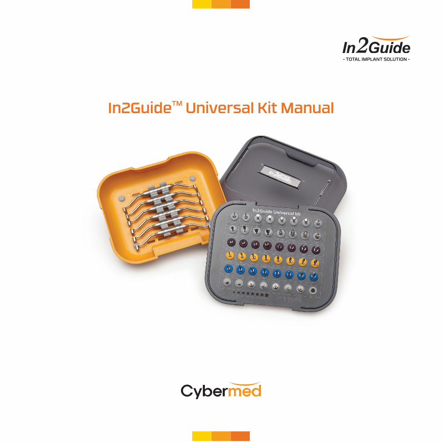
In2GuideTM Universal Kit Manual
- TOTAL IMPLANT SOLUTION -
1. Universal Kit Universal Kit and Components Universal Kit and Components
32
1. Universal Kit1. Universal Kit
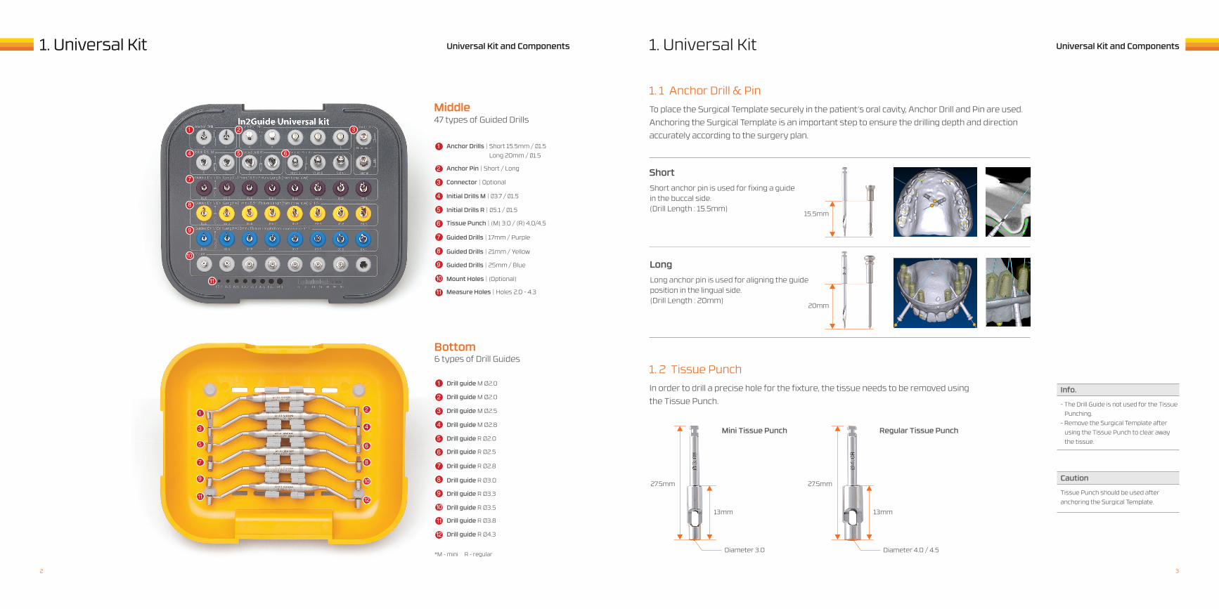
Middle
Bottom
1
1
3
5
7
9
11
2
4
6
8
10
12
Anchor Drills | Short 15.5mm / Ø1.5 Long 20mm / Ø1.5
Drill guide M Ø2.0
1
1
47 types of Guided Drills
6 types of Drill Guides
Anchor Pin | Short / Long
Drill guide M Ø2.0
2
2
Connector | Optional
Drill guide M Ø2.5
3
3
Initial Drills M | Ø3.7 / Ø1.5
Drill guide M Ø2.8
4
4
Initial Drills R | Ø5.1 / Ø1.5
Drill guide R Ø2.0
5
5
Tissue Punch | (M) 3.0 / (R) 4.0/4.5
Drill guide R Ø2.5
6
6
Guided Drills | 17mm / Purple
Drill guide R Ø2.8
7
7
Guided Drills | 21mm / Yellow
Drill guide R Ø3.0
8
8
Guided Drills | 25mm / Blue
Drill guide R Ø3.3
9
9
Mount Holes | (Optional)
Drill guide R Ø3.5
10
10
Measure Holes | Holes 2.0 - 4.3
Drill guide R Ø3.8
Drill guide R Ø4.3
*M - mini R - regular
11
11
12
4
7
8
9
10
11
5 6
2 3
1. 2 Tissue PunchIn order to drill a precise hole for the fixture, the tissue needs to be removed using the Tissue Punch.
Short anchor pin is used for fixing a guide in the buccal side. (Drill Length : 15.5mm)
Long anchor pin is used for aligning the guide position in the lingual side. (Drill Length : 20mm)
Info.
Caution
- The Drill Guide is not used for the Tissue Punching. - Remove the Surgical Template after using the Tissue Punch to clear away the tissue.
Tissue Punch should be used after anchoring the Surgical Template.
13mm 13mm
Diameter 3.0 Diameter 4.0 / 4.5
Mini Tissue Punch Regular Tissue Punch
27.5mm 27.5mm
Short
Long
1. 1 Anchor Drill & PinTo place the Surgical Template securely in the patient’s oral cavity, Anchor Drill and Pin are used. Anchoring the Surgical Template is an important step to ensure the drilling depth and direction accurately according to the surgery plan.
20mm
15.5mm
1. Universal Kit 1. Universal KitUniversal Kit and Components Universal Kit and Components
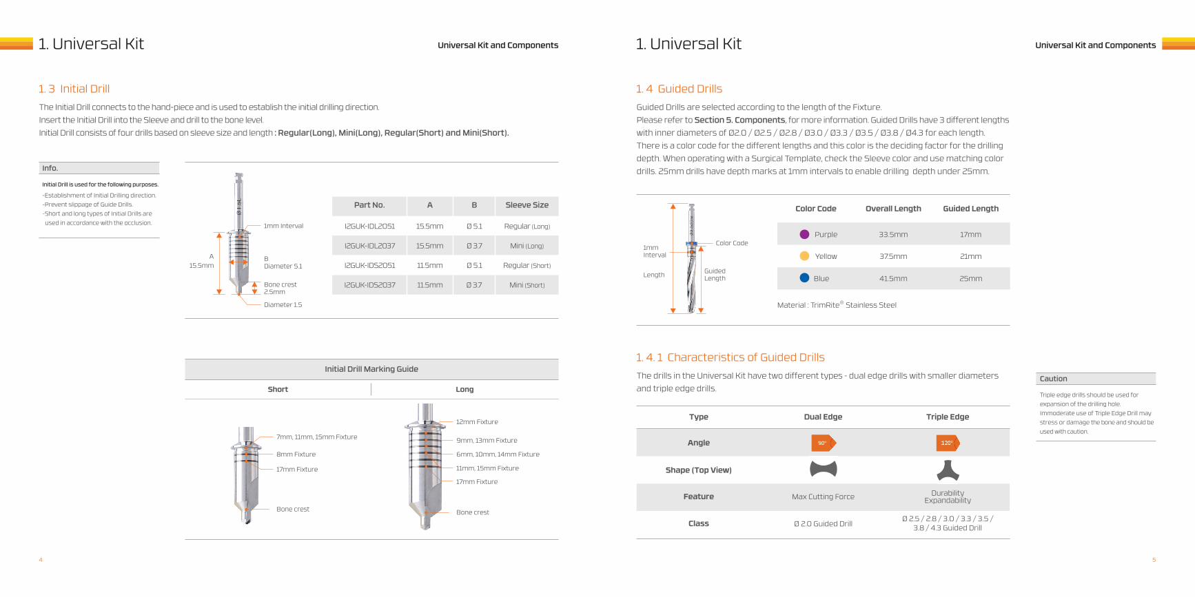
1. 3 Initial DrillThe Initial Drill connects to the hand-piece and is used to establish the initial drilling direction. Insert the Initial Drill into the Sleeve and drill to the bone level. Initial Drill consists of four drills based on sleeve size and length : Regular(Long), Mini(Long), Regular(Short) and Mini(Short).
Bone crest2.5mm
Bone crest
B Diameter 5.1
Diameter 1.5
1mm Interval
7mm, 11mm, 15mm Fixture
8mm Fixture
17mm Fixture
A 15.5mm
Info.
Caution
Part No .
Initial Drill Marking Guide
Short Long
I2GUK-IDL2051
I2GUK-IDL2037
I2GUK-IDS2051
I2GUK-IDS2037
15.5mm
15.5mm
11.5mm
11.5mm
Ø 5.1
Ø 3.7
Ø 5.1
Ø 3.7
Regular (Long)
Mini (Long)
Regular (Short)
Mini (Short)
A B Sleeve Size
Initial Drill is used for the following purposes. -Establishment of Initial Drilling direction.-Prevent slippage of Guide Drills.-Short and long types of Initial Drills are used in accordance with the occlusion.
Triple edge drills should be used for expansion of the drilling hole. Immoderate use of Triple Edge Drill may stress or damage the bone and should be used with caution.
Bone crest
12mm Fixture
9mm, 13mm Fixture
6mm, 10mm, 14mm Fixture
11mm, 15mm Fixture
17mm Fixture
1. 4 Guided Drills
1. 4. 1 Characteristics of Guided Drills
Guided Drills are selected according to the length of the Fixture. Please refer to Section 5. Components, for more information. Guided Drills have 3 different lengths with inner diameters of Ø2.0 / Ø2.5 / Ø2.8 / Ø3.0 / Ø3.3 / Ø3.5 / Ø3.8 / Ø4.3 for each length.There is a color code for the different lengths and this color is the deciding factor for the drilling depth. When operating with a Surgical Template, check the Sleeve color and use matching color drills. 25mm drills have depth marks at 1mm intervals to enable drilling depth under 25mm.
The drills in the Universal Kit have two different types – dual edge drills with smaller diameters and triple edge drills.
Color Code
Length
Purple
Yellow
Blue
Material : TrimRite® Stainless Steel
33.5mm 17mm
37.5mm 21mm
41.5mm 25mm
Color Code
Type
Angle
Feature
Shape (Top View)
Class
Overall Length
Dual Edge
Max Cutting Force
Ø 2.0 Guided Drill
Guided Length
Triple Edge
DurabilityExpandability
Ø 2.5 / 2.8 / 3.0 / 3.3 / 3.5 / 3.8 / 4.3 Guided Drill
Guided Length
1mmInterval
54
1. Universal Kit 1. Universal KitUniversal Kit and Components Universal Kit and Components
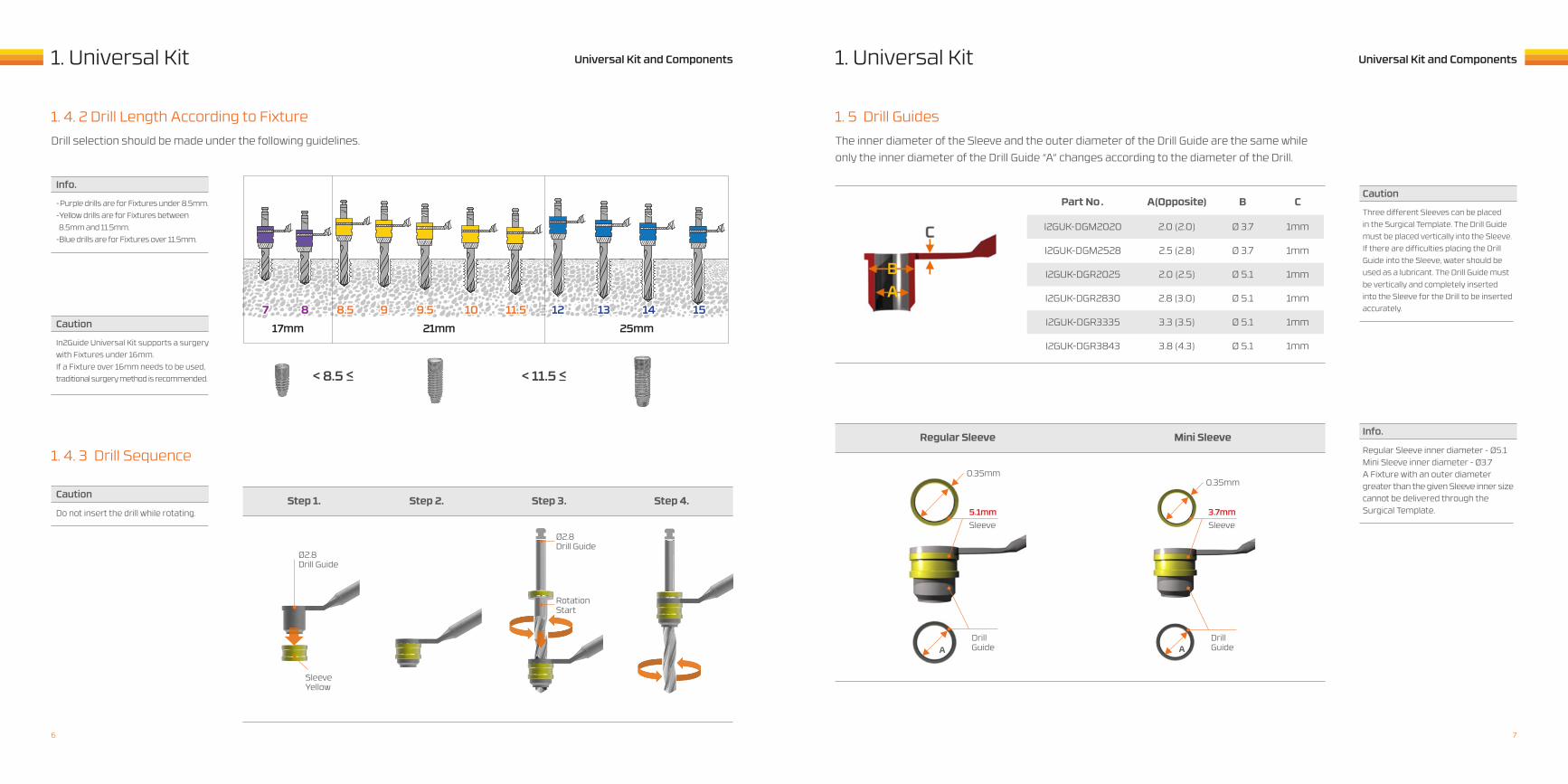
1. 4. 2 Drill Length According to Fixture
1. 4. 3 Drill Sequence
Drill selection should be made under the following guidelines.
7 8 8.5
< 8.5 < < 11.5 <
9 9.5 10 12 13 14 1511.5
Info.
Caution
Caution
-Purple drills are for Fixtures under 8.5mm.-Yellow drills are for Fixtures between 8.5mm and 11.5mm. -Blue drills are for Fixtures over 11.5mm.
In2Guide Universal Kit supports a surgery with Fixtures under 16mm.If a Fixture over 16mm needs to be used, traditional surgery method is recommended.
Do not insert the drill while rotating.Step 1. Step 2. Step 4.Step 3.
Ø2.8Drill Guide
Ø2.8Drill Guide
RotationStart
SleeveYellow
1. 5 Drill Guides
Part No .
I2GUK-DGM2020
I2GUK-DGR2025
I2GUK-DGR3335
I2GUK-DGM2528
I2GUK-DGR2830
I2GUK-DGR3843
2.0 (2.0)
2.0 (2.5)
3.3 (3.5)
2.5 (2.8)
2.8 (3.0)
3.8 (4.3)
Ø 3.7
Ø 5.1
Ø 5.1
Ø 3.7
Ø 5.1
Ø 5.1
1mm
1mm
1mm
1mm
1mm
1mm
A(Opposite) B C
The inner diameter of the Sleeve and the outer diameter of the Drill Guide are the same whileonly the inner diameter of the Drill Guide “A” changes according to the diameter of the Drill.
Caution
Info.
Three different Sleeves can be placed in the Surgical Template. The Drill Guide must be placed vertically into the Sleeve. If there are difficulties placing the Drill Guide into the Sleeve, water should be used as a lubricant. The Drill Guide must be vertically and completely inserted into the Sleeve for the Drill to be inserted accurately.
Regular Sleeve inner diameter - Ø5.1Mini Sleeve inner diameter - Ø3.7A Fixture with an outer diameter greater than the given Sleeve inner size cannot be delivered through the Surgical Template.
Regular Sleeve Mini Sleeve
17mm 21mm 25mm
0.35mm0.35mm
5.1mm 3.7mm
DrillGuideA A
DrillGuide
Sleeve Sleeve
76
Universal Kit and Components Universal Kit and Components2. Surgical Procedures2. Surgical Procedures
Using the Universal Kit, the surgical procedure is shown as above.
Recommended RPM for Drilling
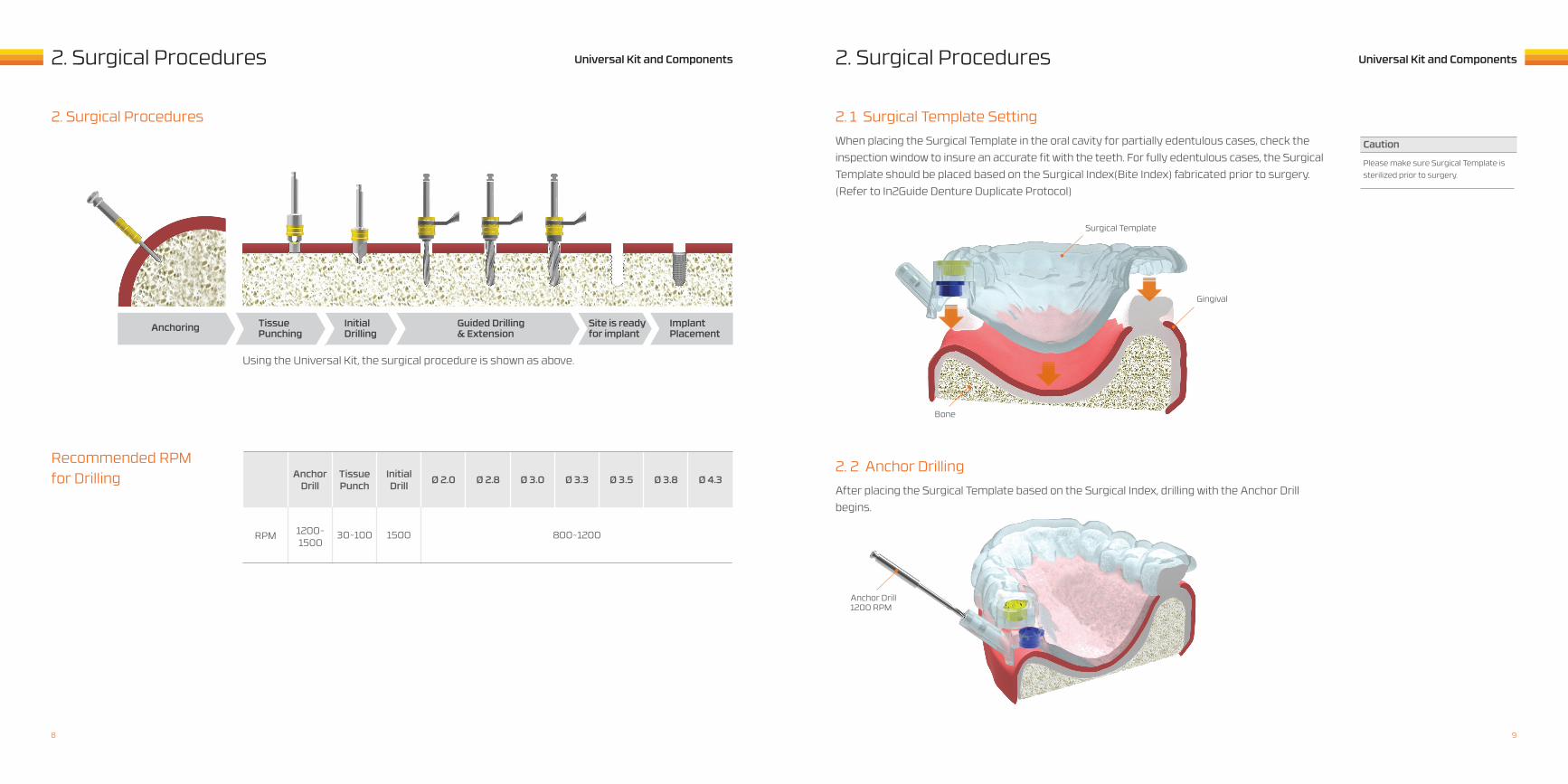
2. Surgical Procedures 2. 1 Surgical Template SettingWhen placing the Surgical Template in the oral cavity for partially edentulous cases, check the inspection window to insure an accurate fit with the teeth. For fully edentulous cases, the Surgical Template should be placed based on the Surgical Index(Bite Index) fabricated prior to surgery. (Refer to In2Guide Denture Duplicate Protocol)
RPM
Ø 3.0Initial Drill
1500
Ø 3.8Anchor Drill
1200~1500
Ø 3.3Ø 2.0
800~1200
Ø 4.3Tissue Punch
30~100
Ø 3.5Ø 2.8
Caution
Please make sure Surgical Template is sterilized prior to surgery.
Bone
Gingival
Surgical Template
2. 2 Anchor DrillingAfter placing the Surgical Template based on the Surgical Index, drilling with the Anchor Drill begins.
Anchor Drill1200 RPM
Anchoring Tissue Punching
Initial Drilling
Guided Drilling& Extension
Site is ready for implant
ImplantPlacement
98
Universal Kit and Components Universal Kit and Components2. Surgical Procedures2. Surgical Procedures
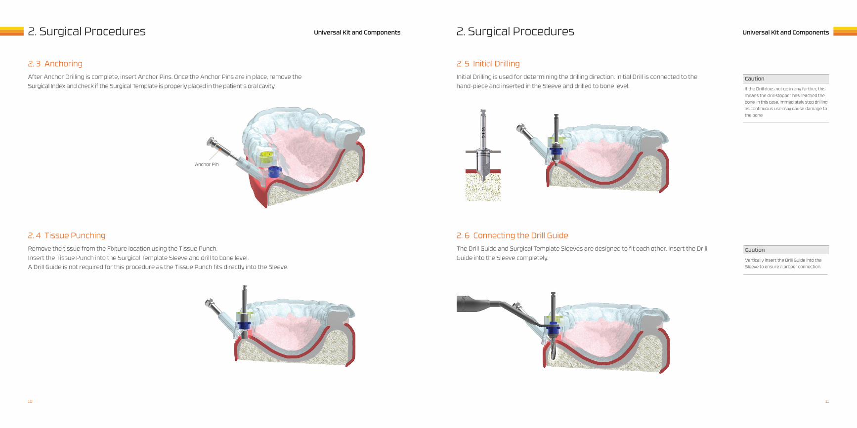
2. 5 Initial Drilling
2. 6 Connecting the Drill Guide
Initial Drilling is used for determining the drilling direction. Initial Drill is connected to the hand-piece and inserted in the Sleeve and drilled to bone level.
The Drill Guide and Surgical Template Sleeves are designed to fit each other. Insert the Drill Guide into the Sleeve completely.
Caution
Caution
If the Drill does not go in any further, this means the drill stopper has reached the bone. In this case, immediately stop drilling as continuous use may cause damage tothe bone.
Vertically insert the Drill Guide into the Sleeve to ensure a proper connection.
2. 3 Anchoring
2. 4 Tissue Punching
After Anchor Drilling is complete, insert Anchor Pins. Once the Anchor Pins are in place, remove the Surgical Index and check if the Surgical Template is properly placed in the patient’s oral cavity.
Remove the tissue from the Fixture location using the Tissue Punch.Insert the Tissue Punch into the Surgical Template Sleeve and drill to bone level.A Drill Guide is not required for this procedure as the Tissue Punch fits directly into the Sleeve.
Anchor Pin
1110
Universal Kit and Components Universal Kit and Components3. In2Guide Mount2. Surgical Procedures
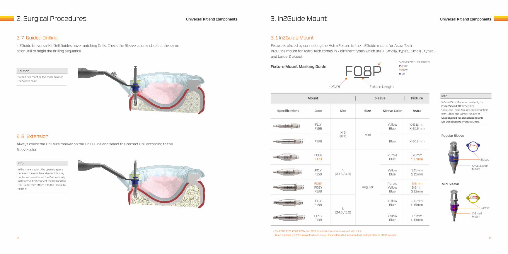
Sleeve color(Drill length)PurpleYellowBlue
Fixture Fixture Length
F08P
3. 1 In2Guide Mount
Fixture Mount Marking Guide
Regular Sleeve
Mini Sleeve
Fixture is placed by connecting the Astra Fixture to the In2Guide mount for Astra Tech.In2Guide mount for Astra Tech comes in 7 different types which are X-Small(2 types), Small(3 types), and Large(2 types).
Mount
Specifications Code Size Sleeve ColorSize Astra
Sleeve
F11YF15B
YellowBlue
X-S 11mmX-S 15mm
X-S(Ø3.0) Mini
Regular
L(Ø4.5 / 5.0)
S(Ø3.5 / 4.0)
F11YF15B
YellowBlue
S 11mmS 15mm
F13B Blue X-S 13mm
F06PF09YF13B
PurpleYellowBlue
S 6mmS 9mmS 13mm
F08PF17B
PurpleBlue
S 8mmS 17mm
F11YF15B
YellowBlue
L 11mmL 15mm
F09YF13B
YellowBlue
L 9mmL 13mm
Fixture
Sleeve
Sleeve
5.1mm
Small, Large Mount
X-SmallMount
3.7mm
2. 7 Guided Drilling
2. 8 Extension
In2Guide Universal Kit Drill Guides have matching Drills. Check the Sleeve color and select the same color Drill to begin the drilling sequence.
Always check the Drill size marker on the Drill Guide and select the correct Drill according to the Sleeve color.
Caution
Info.
Guided Drill must be the same color as the Sleeve color.
In the molar region, the opening space between the maxilla and mandible may not be sufficient to set the Drill vertically. In this case, first connect the Drill and the Drill Guide, then attach it to the Sleeve by tilting it.
Info.
X-Small Size Mount is used only for OsseoSpeed TX 3.0S(Ø3.0). Small and Large Mounts are compatible with Small and Large Fixtures of OsseoSpeed TX, OsseoSpeed and MT OsseoSpeed Product Lines.
*The F08P, F17B, F06P, F09Y, and F13B small size mounts are marked with a line. When installing 6, 17mm implant fixtures, mount the implants to the marked line on the F17B and F06P mounts.
1312
Universal Kit and Components Universal Kit and Components4. Additional Information4. Additional Information
4. 2 Storage
4. 3 Post-surgery Storage
Store the Surgical Template in the UV protection bag along with a dehumidifying agent. Surgical Templates should be used within 30 days.
- During surgery, submerge the used tools in saline solution or distilled water. - After surgery, all tools used should be submerged and cleaned with alcohol.- Rinse in distilled water or running water to remove any stains or foreign substances.- Remove any remaining water with a dry cloth or fan. - Place the clean tools back into the kit case.- Place the kit into an autoclave and dry at 135 Celsius for 10 minutes, then store at room temperature. - Used Surgical Templates should be disposed according to local laws and regulations.
Caution
Caution
The Surgical Template should be used within 30 days to ensure best results.After 30 days, the Surgical Template may become distorted by up to 2% due to the Objet material used in fab-rication. Please contact Cybermed Inc. for assistance.
- Do not use hydrogen peroxide to sterilize the Surgical Template.
- Hydrogen peroxide may damage the laser marking and tin coating.
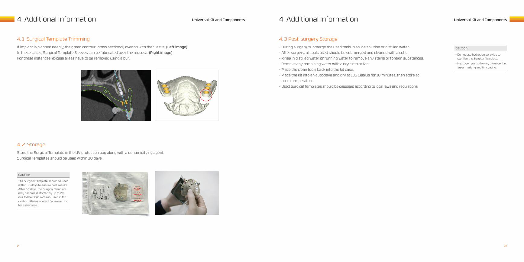
4. 1 Surgical Template TrimmingIf implant is planned deeply, the green contour (cross sectional) overlap with the Sleeve. (Left image) In these cases, Surgical Template Sleeves can be fabricated over the mucosa. (Right image) For these instances, excess areas have to be removed using a bur.
1514
Universal Kit and Components Universal Kit and Components5. Components5. Components
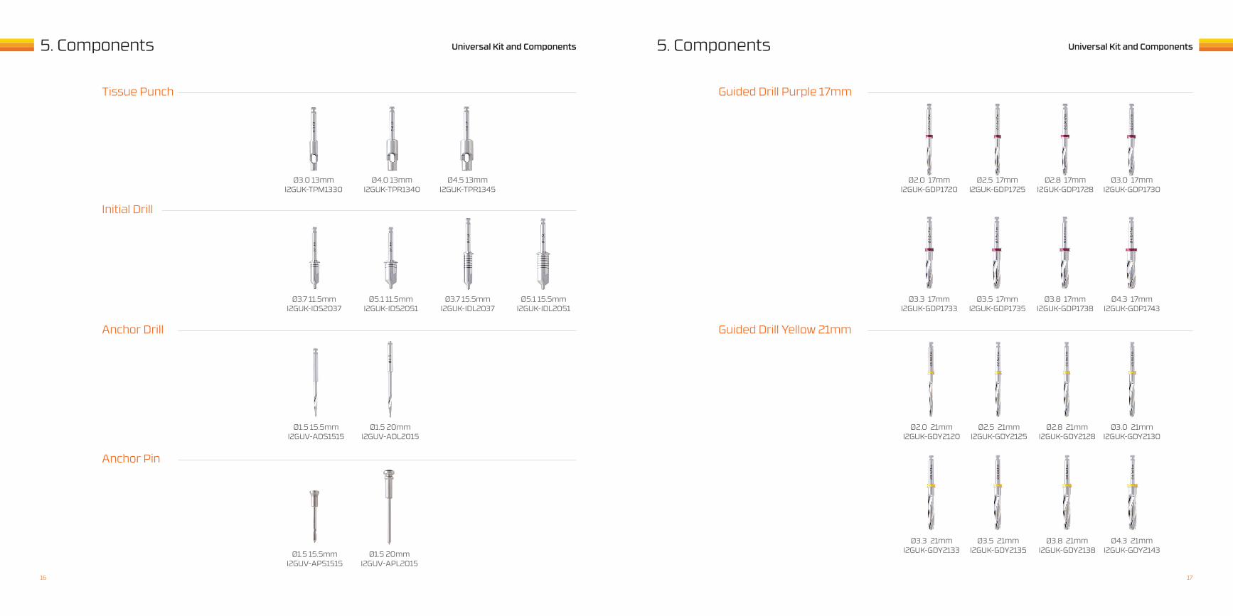
Guided Drill Purple 17mm
Guided Drill Yellow 21mm
Ø2.0 17mmI2GUK-GDP1720
Ø2.0 21mmI2GUK-GDY2120
Ø3.3 17mmI2GUK-GDP1733
Ø3.3 21mmI2GUK-GDY2133
Ø2.5 17mmI2GUK-GDP1725
Ø2.5 21mmI2GUK-GDY2125
Ø3.5 17mmI2GUK-GDP1735
Ø3.5 21mmI2GUK-GDY2135
Ø2.8 17mmI2GUK-GDP1728
Ø2.8 21mmI2GUK-GDY2128
Ø3.8 17mmI2GUK-GDP1738
Ø3.8 21mmI2GUK-GDY2138
Ø3.0 17mmI2GUK-GDP1730
Ø3.0 21mmI2GUK-GDY2130
Ø4.3 17mmI2GUK-GDP1743
Ø4.3 21mmI2GUK-GDY2143
Tissue Punch
Anchor Drill
Initial Drill
Anchor Pin
Ø3.0 13mmI2GUK-TPM1330
Ø1.5 15.5mmI2GUV-APS1515
Ø4.0 13mmI2GUK-TPR1340
Ø1.5 20mmI2GUV-APL2015
Ø4.5 13mmI2GUK-TPR1345
Ø5.1 11.5mmI2GUK-IDS2051
Ø3.7 11.5mmI2GUK-IDS2037
Ø3.7 15.5mmI2GUK-IDL2037
Ø5.1 15.5mmI2GUK-IDL2051
Ø1.5 15.5mmI2GUV-ADS1515
Ø1.5 20mmI2GUV-ADL2015
1716
Universal Kit and Components Universal Kit and Components6. Symbols
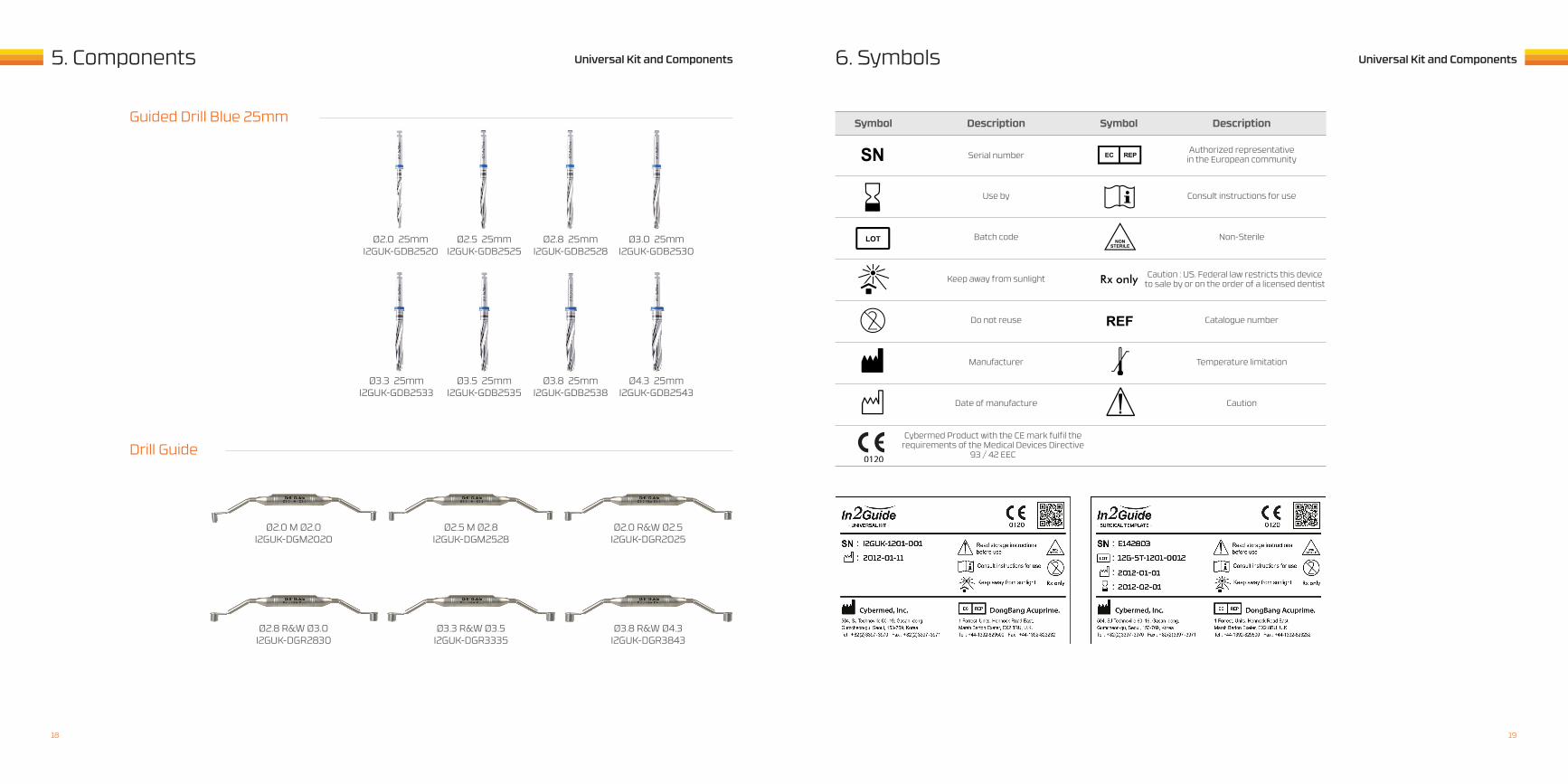
Symbol SymbolDescription Description
Serial number
Use by
Batch code
Keep away from sunlight
Do not reuse
Manufacturer
Date of manufacture
Cybermed Product with the CE mark fulfil the requirements of the Medical Devices Directive
93 / 42 EEC
Authorized representativein the European community
Consult instructions for use
Non-Sterile
Caution : US. Federal law restricts this deviceto sale by or on the order of a licensed dentist
Catalogue number
Temperature limitation
Caution
Ø2.0 25mmI2GUK-GDB2520
Ø2.5 M Ø2.8 I2GUK-DGM2528
Ø3.8 R&W Ø4.3 I2GUK-DGR3843
Ø2.8 R&W Ø3.0 I2GUK-DGR2830
Ø2.0 M Ø2.0 I2GUK-DGM2020
Ø3.3 R&W Ø3.5 I2GUK-DGR3335
Ø2.0 R&W Ø2.5 I2GUK-DGR2025
Ø3.3 25mmI2GUK-GDB2533
Ø2.5 25mmI2GUK-GDB2525
Ø3.5 25mmI2GUK-GDB2535
Ø2.8 25mmI2GUK-GDB2528
Ø3.8 25mmI2GUK-GDB2538
Ø3.0 25mmI2GUK-GDB2530
Ø4.3 25mmI2GUK-GDB2543
5. Components
Guided Drill Blue 25mm
Drill Guide
1918
ww
w.o
ndem
and3
d.co
m
©Cy
berm
ed In
c. 2
012
. All
right
s re
serv
ed.
- TOTAL IMPLANT SOLUTION -
AustraliaPacific OnDemand3D Ltd.,7/2 Calabro Way, Burleigh Heads, QLD 4220, Australia
Tel : +61 1800 725 245Email : [email protected]
USAOnDemand3D Inc. 310 Goddard Way, Suite 250 Irvine, CA 92618, USA
Tel : +1 949 341 0623Email : [email protected] www.ondemand3d.com
MexicoCedirama Digital Avenida Paseo de las Palmas 751-101Lomas de Chapultec, Mexico DF, 11000, Mexico
Tel : +52 55 1088 1859http://www.cedirama.biz/[email protected]
GermanyKaVo Dental GmbHBismarckring 39 88400 Biberach/Riß , Germany
Tel : +49 3088 7206 03 Email : [email protected]
New ZealandPacific OnDemand3D Ltd., 125A Emerson St, Napier 4110, New Zealand
Tel : +64 0800 725 245Email : [email protected]
Korea - HeadquartersCybermed Inc. 504, SJ Technoville 60-19, Gasan-dong,Geumcheon-gu, Seoul 153-769, Korea
Tel : +82 2 3397 3970Email : [email protected] www.ondemand3d.com
IndiaDCIPL 3rd Floor, DCIPL House, Hill Road,Bandra(W) Mumbai 400050, India
Tel : +91 22 26430568 (Distribution)Tel : +91 22 26454230 (Manufacturing)Email : [email protected]
IsraelDental CareHerzel Blvd 1, Ashdod, 77454, Israel
Tel : +972 8 866 3041Email : [email protected] www.dental-care.co.il
Sales and Service ContactsFor further contacts, visit www.ondemand3d.com
Asia - Pacific Americas EMEA