Embed Size (px)
DESCRIPTION
ZTE-ZXSDR-BTS-Structure-and-Principle
Citation preview
ZXSDR BTS Structure and Principle
Agenda
ZXSDR BTS Family Introduction ZXSDR BS8700 ZXSDR BS8800 ZXSDR BS8900 ZXSDR BS8906 ZXSDR BTS Work Principle ZXSDR BTS Operation and Maintenance
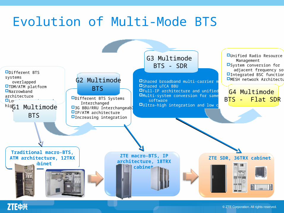
Evolution of Multi-Mode BTS
ZTE macro-BTS, IP architecture, 18TRX cabinet
Traditional macro-BTS, ATM architecture, 12TRX cabinet Traditional macro-BTS, ATM architecture, 12TRX cabinet
Different BTS systems overlappedTDM/ATM platformNarrowband architectureLow integration and high consumption
G1 Multimode BTS
Different BTS Systems Interchanged3G BBU/RRU Interchangeable IP/ATM architectureIncreasing integration
G2 Multimode BTS
Shared broadband multi-carrier moduleShared uTCA BBUFull-IP architecture and unified platformMulti-system conversion for same frequency softwareUltra-high integration and low consumption
G3 Multimode BTS - SDR
Unified Radio Resource ManagementSystem conversion for adjacent frequency softwareIntegrated BSC functionMESH network Architecture
G4 Multimode BTS - Flat SDR
ZTE SDR, 36TRX cabinet
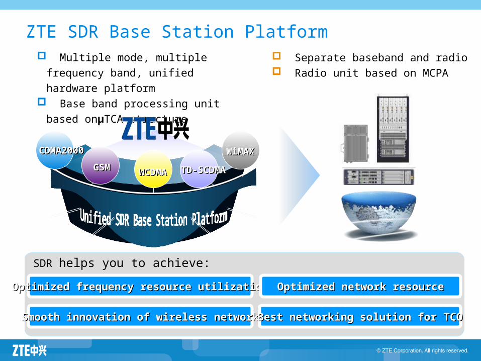
ZTE SDR Base Station Platform Multiple mode, multiple frequency
band, unified hardware platform Base band processing unit based
onμTCA structure
SDR helps you to achieve:
OptimizedOptimized frequency resource utilizationfrequency resource utilization Optimized networkOptimized network resourceresource
Smooth innovation of wirelessSmooth innovation of wireless networknetwork Best networking solution forBest networking solution for TCOTCO
Separate baseband and radio Radio unit based on MCPA
CDMA2000CDMA2000
GSMGSM
TD-SCDMATD-SCDMA
WiMAXWiMAX
WCDMAWCDMA
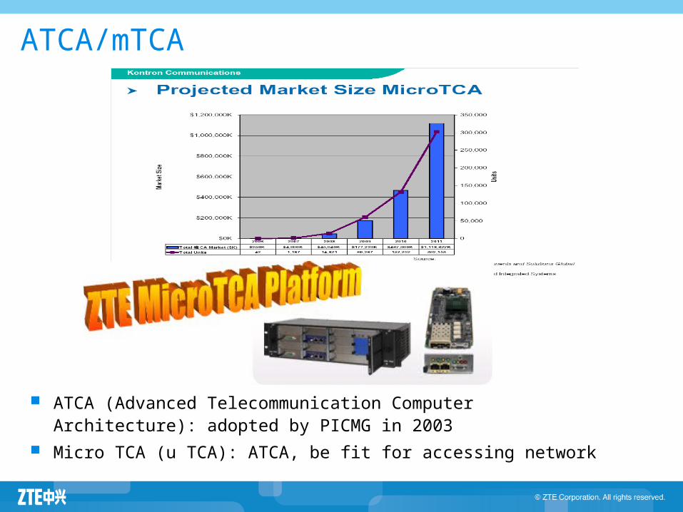
ATCA/mTCA
ATCA (Advanced Telecommunication Computer Architecture): adopted by PICMG in 2003
Micro TCA (u TCA): ATCA, be fit for accessing network
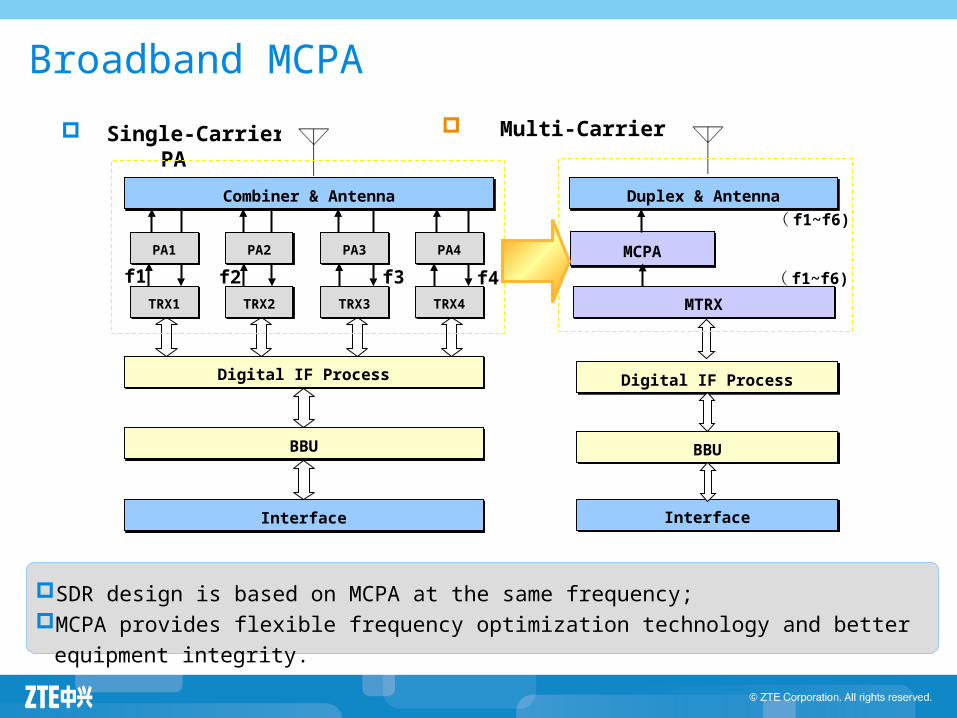
Broadband MCPA
Single-Carrier PA Multi-Carrier PA
Combiner & AntennaCombiner & Antenna
InterfaceInterface
Digital IF ProcessDigital IF Process
BBUBBU
PA1PA1
TRX1TRX1
PA2PA2
TRX2TRX2
PA3PA3
TRX3TRX3
PA4PA4
TRX4TRX4
f1 f2 f3 f4
Duplex & AntennaDuplex & Antenna
MCPAMCPA
MTRXMTRX
InterfaceInterface
BBUBBU
Digital IF ProcessDigital IF Process
( f1~f6)
( f1~f6)
SDR design is based on MCPA at the same frequency; MCPA provides flexible frequency optimization technology and better equipment integrity.
BS8700
BS8900
BS8800
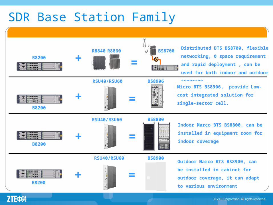
Distributed BTS BS8700, flexible
networking, 0 space requirement and
rapid deployment , can be used for both
indoor and outdoor coverage
B8200
R8860
RSU40/RSU60
+
+ =
Indoor Marco BTS BS8800, can be
installed in equipment room for indoor
coverage
RSU40/RSU60
+ =
Outdoor Marco BTS BS8900, can be
installed in cabinet for outdoor
coverage, it can adapt to various
environment
=
B8200
B8200
Micro BTS BS8906, provide Low-cost
integrated solution for single-sector
cell.
BS8906
+ =B8200
RSU40/RSU60
R8840
SDR Base Station Family
RRUBBU
Indoor Macro
OutdoorMacro
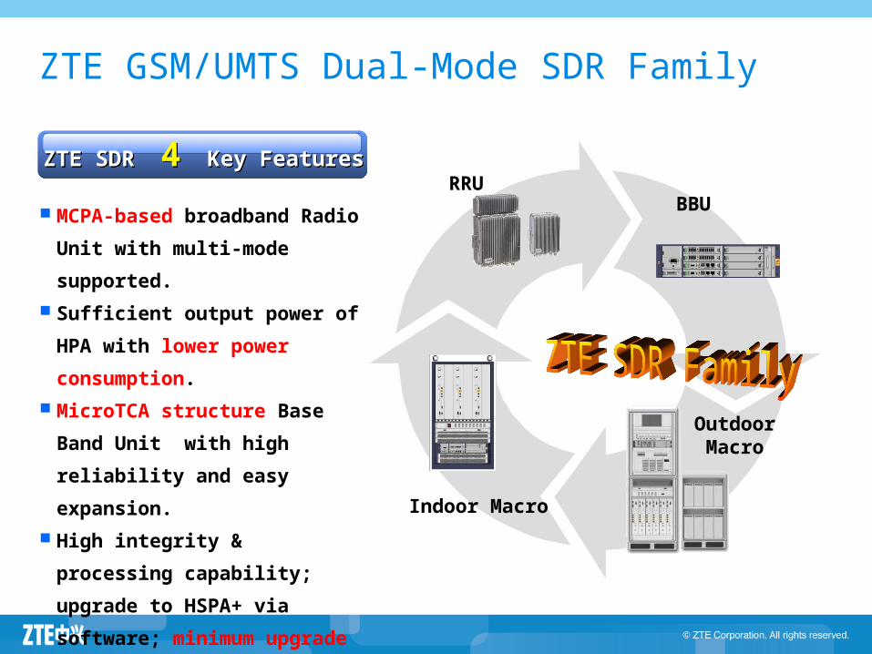
MCPA-based broadband Radio
Unit with multi-mode supported.
Sufficient output power of HPA
with lower power consumption.
MicroTCA structure Base Band
Unit with high reliability and
easy expansion.
High integrity & processing
capability; upgrade to HSPA+ via
software; minimum upgrade cost
to support LTE.
ZTE SDR 4 Key FeaturesZTE SDR 4 Key Features
ZTE GSM/UMTS Dual-Mode SDR Family
Agenda
ZXSDR BTS Family Introduction ZXSDR BS8700 ZXSDR BS8800 ZXSDR BS8900 ZXSDR BS8906 ZXSDR BTS Work Principle ZXSDR BTS Operation and Maintenance
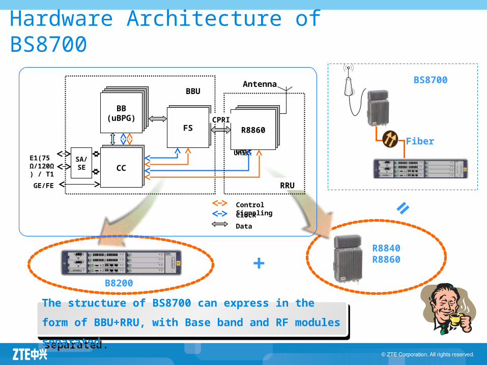
Hardware Architecture of BS8700
B8200
+
=
R8840R8860
BS8700
Fiber
BBU
Radio UnitRadio Unit
SA/SE CC
BB(uBPG)
FS R8860
E1(75 Ω/120Ω) / T1
GE/FE
Clock
Data
Control Signaling
Antenna
RRU
CPRI
The structure of BS8700 can express in the form of
BBU+RRU, with Base band and RF modules separated.
The structure of BS8700 can express in the form of
BBU+RRU, with Base band and RF modules separated.
B8200 accomplishes the following basic functions with RRU in Um/Uu, Abis/Iub and O&M interfaces.
RRU and B8200 accomplishes UE access and radio link transmission including RF processing, channel coding and decoding, channel multiplexing and de-multiplexing, measuring and reporting, power control, transmit diversity, receiving diversity, calibration and synchronization.
With Abis/Iub interface, RRU and B8200 connects with BSC/RNC and accomplishes the following functions including cell management, reporting BTS measurement information, broadcasting system Information, implementing access control from BSC/RNC, mobility management, radio resource management and controlling, FP processing and transmission management.
With operating and maintenance interface, B8200 provides system management functions including configuration management, alarm
management, status checking and system monitoring
ZXSDR B8200 Introduction
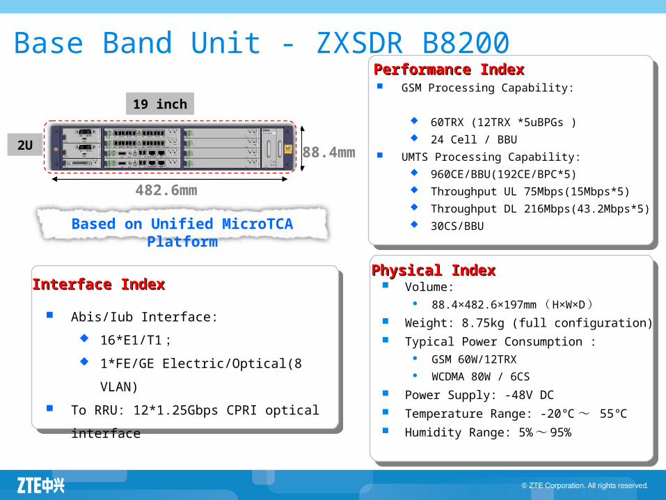
Based on Unified MicroTCA Platform
Base Band Unit - ZXSDR B8200
Volume: 88.4×482.6×197mm ( H×W×D )
Weight: 8.75kg (full configuration) Typical Power Consumption :
GSM 60W/12TRX WCDMA 80W / 6CS
Power Supply: -48V DC Temperature Range: -20℃~ 55℃ Humidity Range: 5% ~ 95%
2U
482.6mm
88.4mm
GSM Processing Capability: 60TRX (12TRX *5uBPGs ) 24 Cell / BBU
UMTS Processing Capability: 960CE/BBU(192CE/BPC*5) Throughput UL 75Mbps(15Mbps*5) Throughput DL 216Mbps(43.2Mbps*5) 30CS/BBU
Abis/Iub Interface:
16*E1/T1 ; 1*FE/GE Electric/Optical(8 VLAN)
To RRU: 12*1.25Gbps CPRI optical interface
Performance IndexPerformance Index
Physical IndexPhysical IndexInterface IndexInterface Index
19 inch
PM Board Introduction
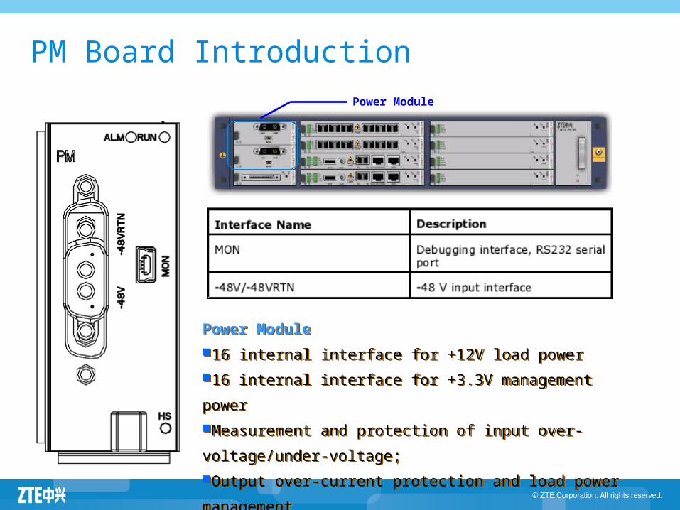
Power Module
16 internal interface for +12V load power
16 internal interface for +3.3V management power
Measurement and protection of input over-voltage/under-
voltage;
Output over-current protection and load power management
Power Module
16 internal interface for +12V load power
16 internal interface for +3.3V management power
Measurement and protection of input over-voltage/under-
voltage;
Output over-current protection and load power management
Power Module
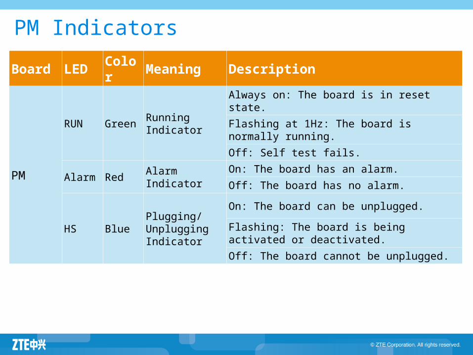
Board LED Color Meaning Description
PM
RUN GreenRunning Indicator
Always on: The board is in reset state.
Flashing at 1Hz: The board is normally running.
Off: Self test fails.
Alarm Red Alarm IndicatorOn: The board has an alarm.
Off: The board has no alarm.
HS BluePlugging/Unplugging Indicator
On: The board can be unplugged.
Flashing: The board is being activated or deactivated.
Off: The board cannot be unplugged.
PM Indicators
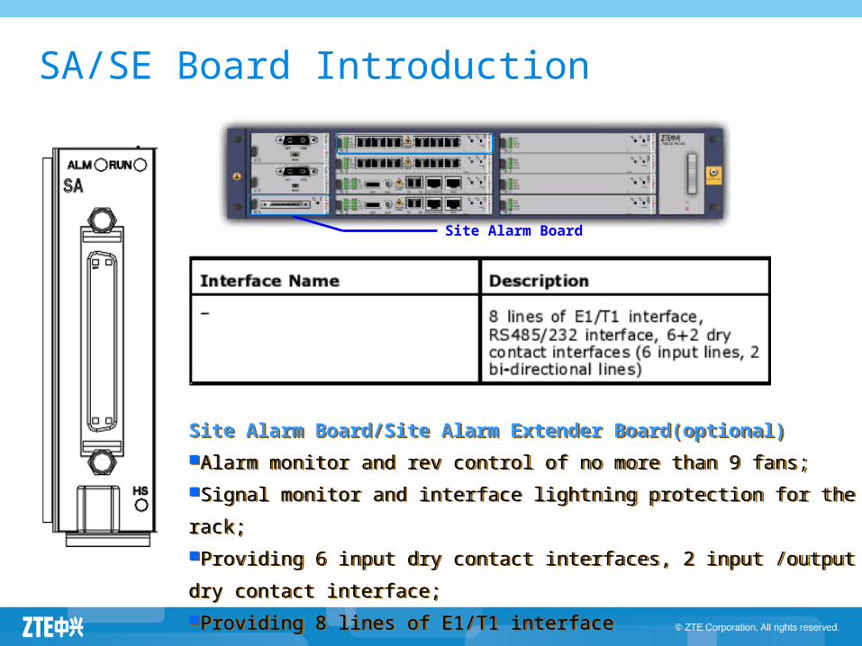
SA/SE Board Introduction
Site Alarm Board
Site Alarm Board/Site Alarm Extender Board(optional)
Alarm monitor and rev control of no more than 9 fans;
Signal monitor and interface lightning protection for the rack;
Providing 6 input dry contact interfaces, 2 input /output dry contact interface;
Providing 8 lines of E1/T1 interface
Site Alarm Board/Site Alarm Extender Board(optional)
Alarm monitor and rev control of no more than 9 fans;
Signal monitor and interface lightning protection for the rack;
Providing 6 input dry contact interfaces, 2 input /output dry contact interface;
Providing 8 lines of E1/T1 interface
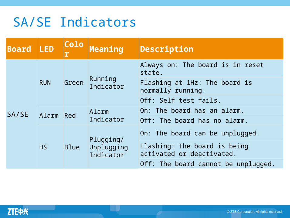
Board LED Color Meaning Description
SA/SE
RUN GreenRunning Indicator
Always on: The board is in reset state.
Flashing at 1Hz: The board is normally running.
Off: Self test fails.
Alarm Red Alarm IndicatorOn: The board has an alarm.
Off: The board has no alarm.
HS BluePlugging/Unplugging Indicator
On: The board can be unplugged.
Flashing: The board is being activated or deactivated.
Off: The board cannot be unplugged.
SA/SE Indicators
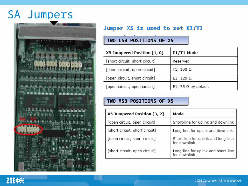
SA JumpersJumper X5 is used to set E1/T1 transmission
mode.
Jumper X5 is used to set E1/T1 transmission
mode.TWO LSB POSITIONS OF X5TWO LSB POSITIONS OF X5
TWO MSB POSITIONS OF X5TWO MSB POSITIONS OF X5
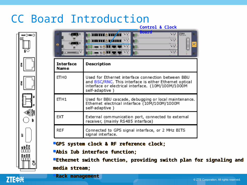
CC Board Introduction
GPS system clock & RF reference clock;
Abis Iub interface function;
Ethernet switch function, providing switch plan for signaling and media stream;
Rack management
GPS system clock & RF reference clock;
Abis Iub interface function;
Ethernet switch function, providing switch plan for signaling and media stream;
Rack management
Control & Clock Board
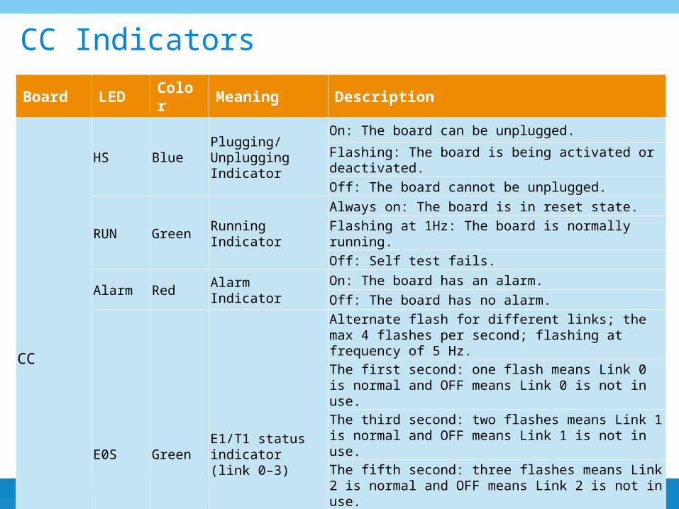
Board LED Color Meaning Description
CC
HS BluePlugging/Unplugging Indicator
On: The board can be unplugged.
Flashing: The board is being activated or deactivated.
Off: The board cannot be unplugged.
RUN Green Running Indicator
Always on: The board is in reset state.
Flashing at 1Hz: The board is normally running.
Off: Self test fails.
Alarm Red Alarm IndicatorOn: The board has an alarm.
Off: The board has no alarm.
E0S GreenE1/T1 status indicator (link 0–3)
Alternate flash for different links; the max 4 flashes per second; flashing at frequency of 5 Hz.
The first second: one flash means Link 0 is normal and OFF means Link 0 is not in use.
The third second: two flashes means Link 1 is normal and OFF means Link 1 is not in use.
The fifth second: three flashes means Link 2 is normal and OFF means Link 2 is not in use.
The seventh second: four flashes means Link 3 is normal.
and OFF means Link 3 is not in use.
Recycle. Each cycle lasts for eight seconds.
CC Indicators
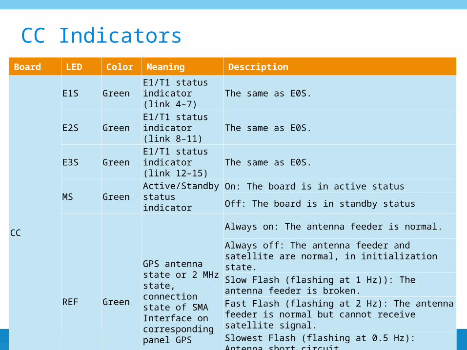
Board LED Color Meaning Description
CC
E1S GreenE1/T1 status indicator (link 4–7)
The same as E0S.
E2S GreenE1/T1 status indicator (link 8–11)
The same as E0S.
E3S GreenE1/T1 status indicator (link 12–15)
The same as E0S.
MS GreenActive/Standby status indicator
On: The board is in active status
Off: The board is in standby status
REF Green
GPS antenna state or 2 MHz state, connection state of SMA Interface on corresponding panel GPS
Always on: The antenna feeder is normal.
Always off: The antenna feeder and satellite are normal, in initialization state.
Slow Flash (flashing at 1 Hz)): The antenna feeder is broken.
Fast Flash (flashing at 2 Hz): The antenna feeder is normal but cannot receive satellite signal.
Slowest Flash (flashing at 0.5 Hz): Antenna short circuit
Quickest Flash (flashing at 5 Hz): No message is received at the initialization stage.
CC Indicators
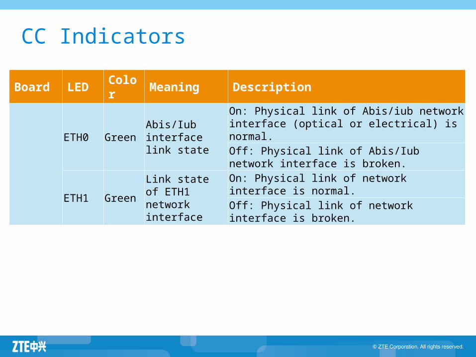
Board LED Color Meaning Description
ETH0 GreenAbis/Iub interface link state
On: Physical link of Abis/iub network interface (optical or electrical) is normal.Off: Physical link of Abis/Iub network interface is broken.
ETH1 GreenLink state of ETH1 network interface
On: Physical link of network interface is normal.
Off: Physical link of network interface is broken.
CC Indicators
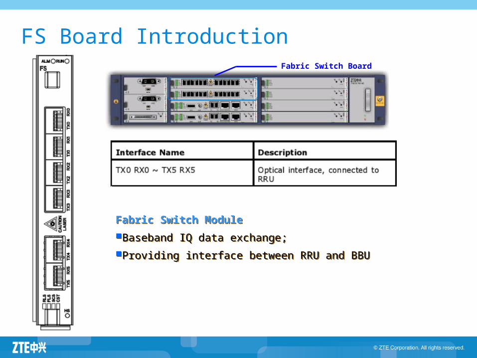
FS Board IntroductionFabric Switch Board
Fabric Switch Module
Baseband IQ data exchange;
Providing interface between RRU and BBU
Fabric Switch Module
Baseband IQ data exchange;
Providing interface between RRU and BBU
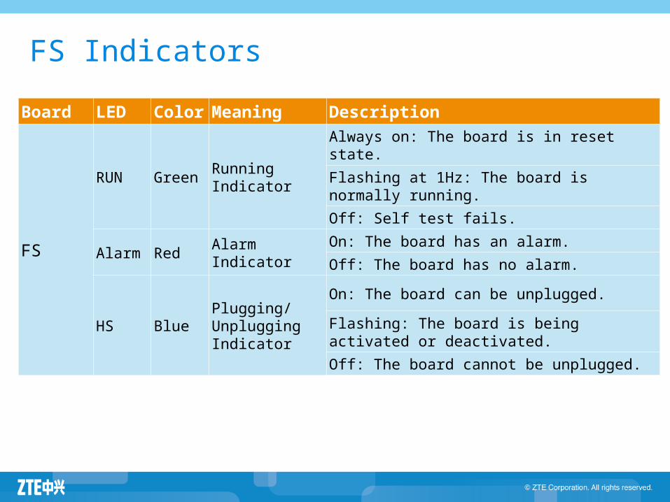
Board LED Color Meaning Description
FS
RUN GreenRunning Indicator
Always on: The board is in reset state.
Flashing at 1Hz: The board is normally running.
Off: Self test fails.
Alarm Red Alarm IndicatorOn: The board has an alarm.
Off: The board has no alarm.
HS BluePlugging/Unplugging Indicator
On: The board can be unplugged.
Flashing: The board is being activated or deactivated.
Off: The board cannot be unplugged.
FS Indicators
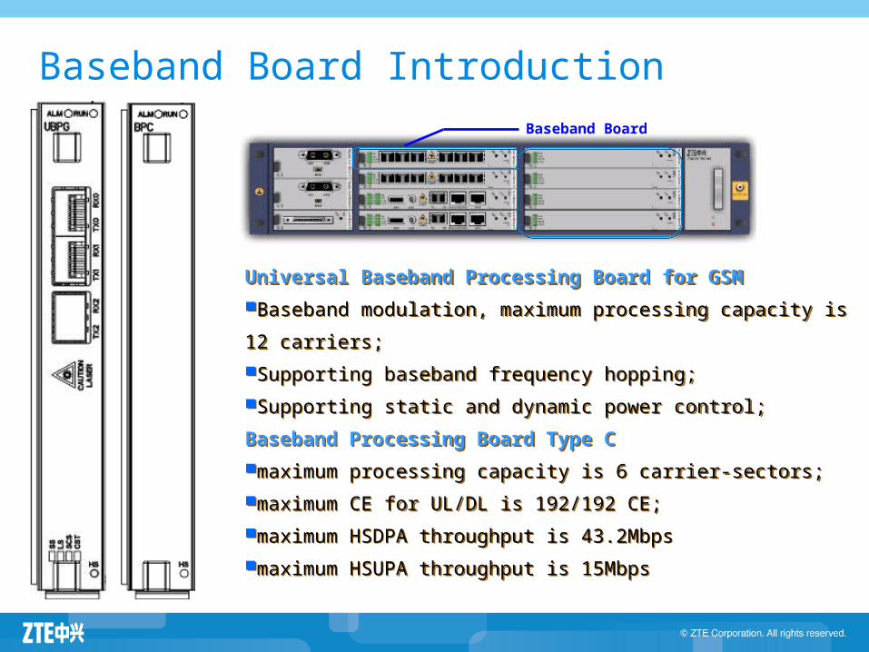
Baseband Board Introduction
Baseband Board
Universal Baseband Processing Board for GSM
Baseband modulation, maximum processing capacity is 12 carriers;
Supporting baseband frequency hopping;
Supporting static and dynamic power control;
Baseband Processing Board Type C
maximum processing capacity is 6 carrier-sectors;
maximum CE for UL/DL is 192/192 CE;
maximum HSDPA throughput is 43.2Mbps
maximum HSUPA throughput is 15Mbps
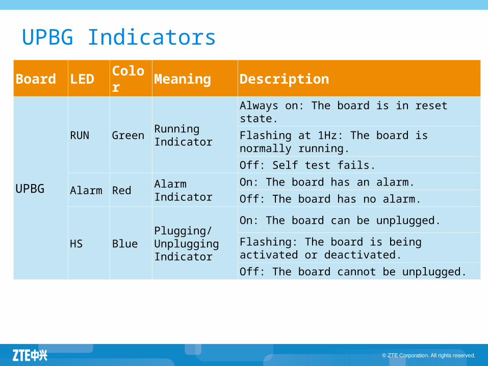
Board LED Color Meaning Description
UPBG
RUN GreenRunning Indicator
Always on: The board is in reset state.
Flashing at 1Hz: The board is normally running.
Off: Self test fails.
Alarm Red Alarm IndicatorOn: The board has an alarm.
Off: The board has no alarm.
HS BluePlugging/Unplugging Indicator
On: The board can be unplugged.
Flashing: The board is being activated or deactivated.
Off: The board cannot be unplugged.
UPBG Indicators
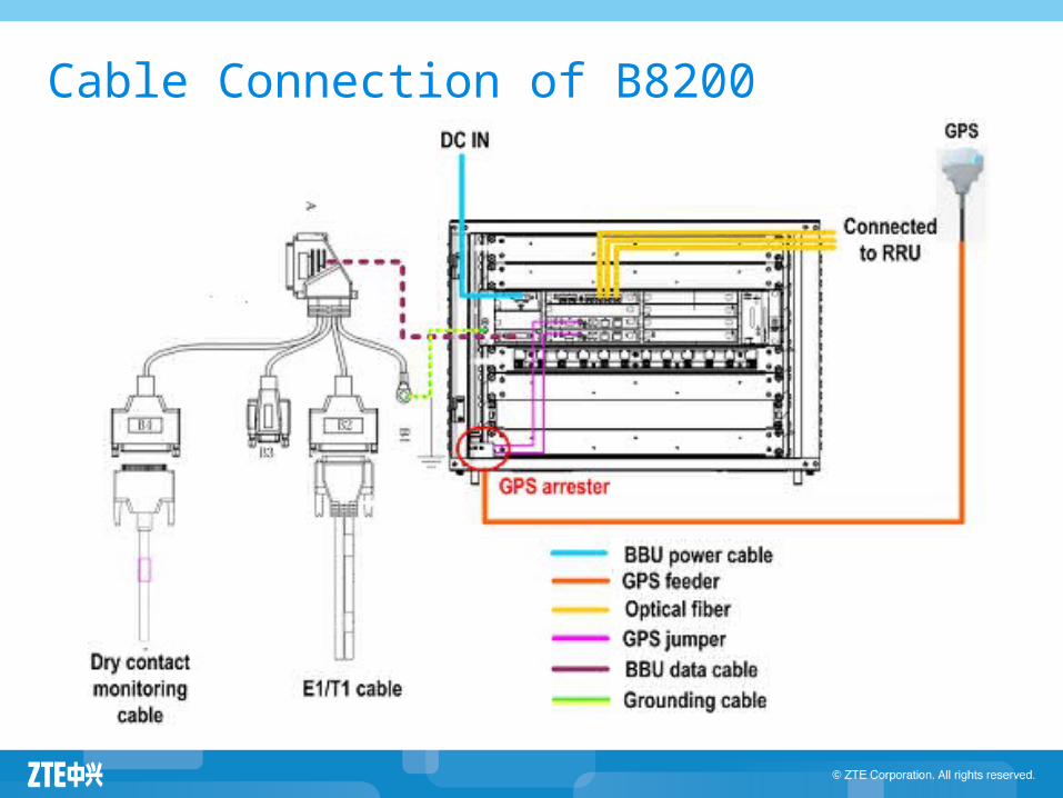
Cable Connection of B8200
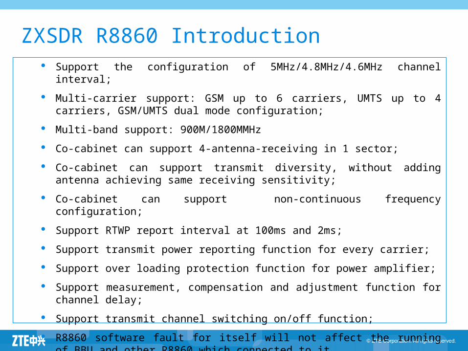
ZXSDR R8860 Introduction Support the configuration of 5MHz/4.8MHz/4.6MHz channel interval;
Multi-carrier support: GSM up to 6 carriers, UMTS up to 4 carriers, GSM/UMTS dual mode configuration;
Multi-band support: 900M/1800MMHz
Co-cabinet can support 4-antenna-receiving in 1 sector;
Co-cabinet can support transmit diversity, without adding antenna achieving same receiving sensitivity;
Co-cabinet can support non-continuous frequency configuration;
Support RTWP report interval at 100ms and 2ms;
Support transmit power reporting function for every carrier;
Support over loading protection function for power amplifier;
Support measurement, compensation and adjustment function for channel delay;
Support transmit channel switching on/off function;
R8860 software fault for itself will not affect the running of BBU and other R8860 which connected to it.
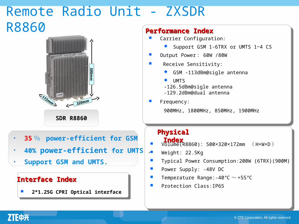
Remote Radio Unit - ZXSDR R8860
SDR R8860
Carrier Configuration:
Support GSM 1-6TRX or UMTS 1~4 CS
Output Power : 60W /80W
Receive Sensitivity:
GSM -113dBm@sigle antenna
UMTS -126.5dBm@sigle antenna-129.2dBm@dual antenna
Frequency:
900MHz, 1800MHz, 850MHz, 1900MHz
Performance IndexPerformance Index
2*1.25G CPRI Optical interface
Interface IndexInterface Index
Volume(R8860): 500×320×172mm ( H×W×D ) Weight: 22.5Kg
Typical Power Consumption:200W (6TRX)(900M)
Power Supply: -48V DC
Temperature Range:-40℃~ +55℃
Protection Class:IP65
Physical IndexPhysical Index
50
0mm
320mm172mm
• 35 % power-efficient for GSM
• 40% power-efficient for UMTS .
• Support GSM and UMTS.
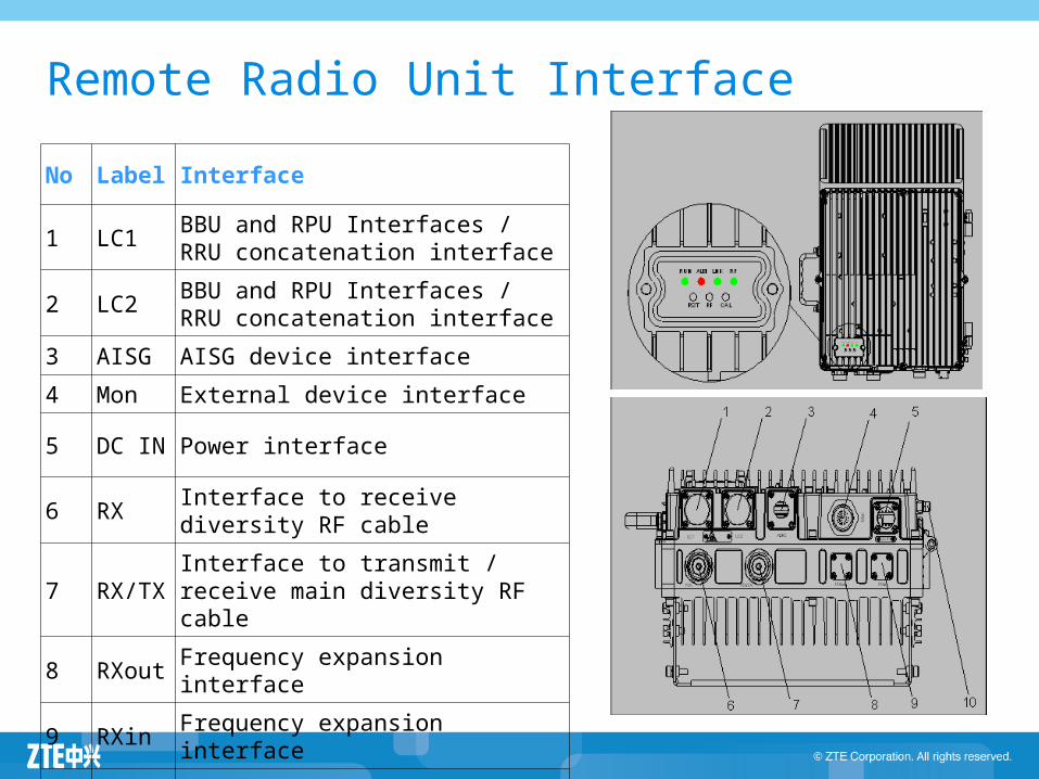
Remote Radio Unit Interface
No Label Interface
1 LC1BBU and RPU Interfaces / RRU concatenation interface
2 LC2BBU and RPU Interfaces / RRU concatenation interface
3 AISG AISG device interface
4 Mon External device interface
5 DC IN Power interface
6 RXInterface to receive diversity RF cable
7 RX/TXInterface to transmit / receive main diversity RF cable
8 RXout Frequency expansion interface
9 RXin Frequency expansion interface
10 GND Machine Grounding
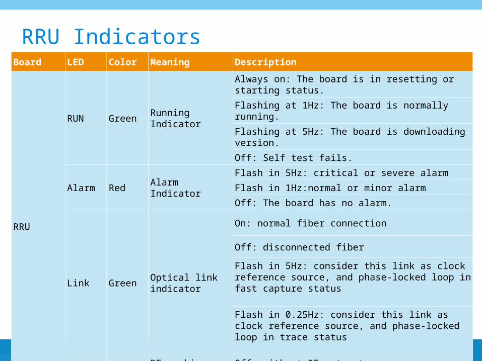
Board LED Color Meaning Description
RRU
RUN Green Running Indicator
Always on: The board is in resetting or starting status.
Flashing at 1Hz: The board is normally running.
Flashing at 5Hz: The board is downloading version.
Off: Self test fails.
Alarm Red Alarm Indicator
Flash in 5Hz: critical or severe alarm
Flash in 1Hz:normal or minor alarm
Off: The board has no alarm.
Link GreenOptical link indicator
On: normal fiber connection
Off: disconnected fiber
Flash in 5Hz: consider this link as clock reference source, and phase-locked loop in fast capture status
Flash in 0.25Hz: consider this link as clock reference source, and phase-locked loop in trace status
RF OrangeRF working status indicator
Off: without RF out put
On: with RF out put
RRU Indicators
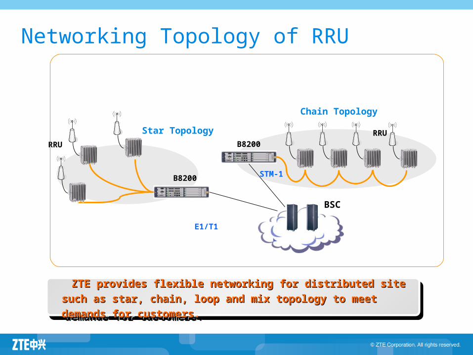
Star Topology
Chain Topology
BSC
E1/T1
STM-1
B8200
B8200
RRU
RRU
ZTE provides flexible networking for distributed site such as star, ZTE provides flexible networking for distributed site such as star,
chain, loop and mix topology to meet demands for customers.chain, loop and mix topology to meet demands for customers.
ZTE provides flexible networking for distributed site such as star, ZTE provides flexible networking for distributed site such as star,
chain, loop and mix topology to meet demands for customers.chain, loop and mix topology to meet demands for customers.
Networking Topology of RRU
Agenda
ZXSDR BTS Family Introduction ZXSDR BS8700 ZXSDR BS8800 ZXSDR BS8900 ZXSDR BS8906 ZXSDR BTS Work Principle ZXSDR BTS Operation and Maintenance
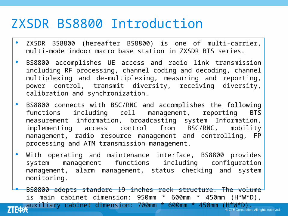
ZXSDR BS8800 Introduction ZXSDR BS8800 (hereafter BS8800) is one of multi-carrier, multi-mode indoor
macro base station in ZXSDR BTS series.
BS8800 accomplishes UE access and radio link transmission including RF processing, channel coding and decoding, channel multiplexing and de-multiplexing, measuring and reporting, power control, transmit diversity, receiving diversity, calibration and synchronization.
BS8800 connects with BSC/RNC and accomplishes the following functions including cell management, reporting BTS measurement information, broadcasting system Information, implementing access control from BSC/RNC, mobility management, radio resource management and controlling, FP processing and ATM transmission management.
With operating and maintenance interface, BS8800 provides system management functions including configuration management, alarm management, status checking and system monitoring.
BS8800 adopts standard 19 inches rack structure. The volume is main cabinet dimension: 950mm * 600mm * 450mm (H*W*D), auxiliary cabinet dimension: 700mm * 600mm * 450mm (H*W*D).
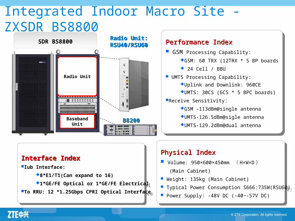
Integrated Indoor Macro Site - ZXSDR BS8800
Radio Unit
BasebandUnit
Radio Unit:RSU40/RSU60
Radio Unit:RSU40/RSU60
Physical IndexPhysical Index Volume: 950×600×450mm ( H×W×D ) (Main Cabinet)
Weight: 135kg (Main Cabinet)
Typical Power Consumption S666:735W(RSU60)
Power Supply: -48V DC (-40~-57V DC)
Physical IndexPhysical Index Volume: 950×600×450mm ( H×W×D ) (Main Cabinet)
Weight: 135kg (Main Cabinet)
Typical Power Consumption S666:735W(RSU60)
Power Supply: -48V DC (-40~-57V DC)
Performance IndexPerformance Index GSM Processing Capability:
GSM: 60 TRX (12TRX * 5 BP boards
24 Cell / BBU
UMTS Processing Capability:Uplink and Downlink: 960CEUMTS: 30CS (6CS * 5 BPC boards)
Receive Sensitivity:
GSM -113dBm@single antenna
UMTS-126.5dBm@sigle antenna
UMTS-129.2dBm@dual antenna
Performance IndexPerformance Index GSM Processing Capability:
GSM: 60 TRX (12TRX * 5 BP boards
24 Cell / BBU
UMTS Processing Capability:Uplink and Downlink: 960CEUMTS: 30CS (6CS * 5 BPC boards)
Receive Sensitivity:
GSM -113dBm@single antenna
UMTS-126.5dBm@sigle antenna
UMTS-129.2dBm@dual antenna
Interface IndexInterface IndexIub Interface:
8*E1/T1(Can expand to 16)
1*GE/FE Optical or 1*GE/FE Electrical
To RRU: 12 *1.25Gbps CPRI Optical Interface
Interface IndexInterface IndexIub Interface:
8*E1/T1(Can expand to 16)
1*GE/FE Optical or 1*GE/FE Electrical
To RRU: 12 *1.25Gbps CPRI Optical Interface
SDR BS8800
B8200B8200
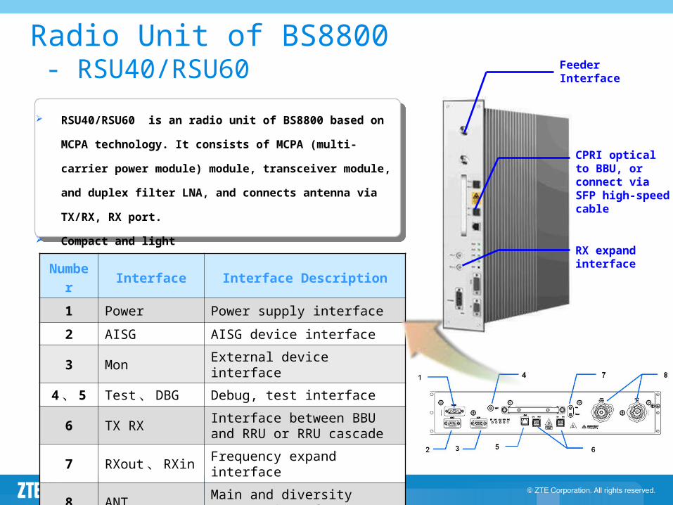
Radio Unit of BS8800 - RSU40/RSU60
RSU40/RSU60 is an radio unit of BS8800 based on MCPA
technology. It consists of MCPA (multi-carrier power module)
module, transceiver module, and duplex filter LNA, and
connects antenna via TX/RX, RX port.
Compact and light
Feeder Interface
CPRI optical to BBU, or connect via SFP high-speed cable
RX expand interfaceNumbe
rInterface Interface Description
1 Power Power supply interface
2 AISG AISG device interface
3 Mon External device interface
4 、 5 Test 、 DBG Debug, test interface
6 TX RXInterface between BBU and RRU or RRU cascade
7 RXout 、 RXin Frequency expand interface
8 ANTMain and diversity antenna interface
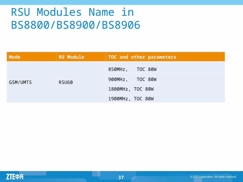
RSU Modules Name in BS8800/BS8900/BS8906
Mode RU Module TOC and other parameters
GSM/UMTS RSU60
850MHz, TOC 80W
900MHz, TOC 80W
1800MHz, TOC 80W
1900MHz, TOC 80W
37
38
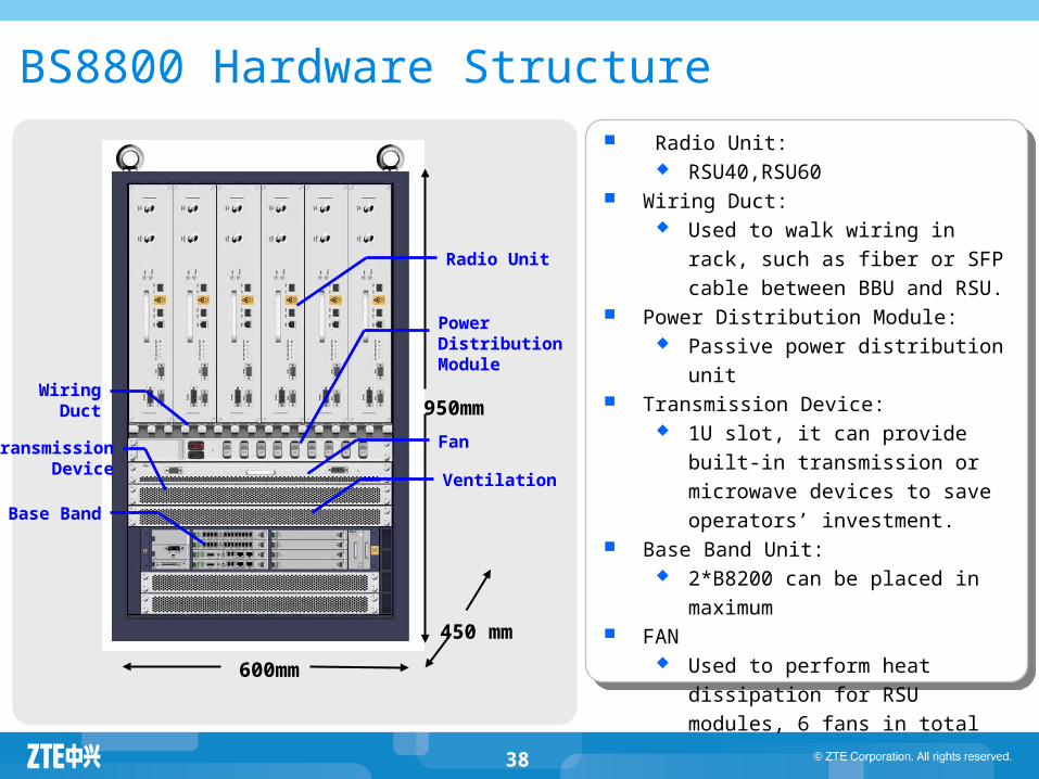
Radio Unit: RSU40,RSU60
Wiring Duct: Used to walk wiring in rack, such
as fiber or SFP cable between BBU
and RSU. Power Distribution Module:
Passive power distribution unit Transmission Device:
1U slot, it can provide built-in
transmission or microwave devices
to save operators’ investment. Base Band Unit:
2*B8200 can be placed in
maximum FAN
Used to perform heat dissipation
for RSU modules, 6 fans in total
BS8800 Hardware Structure
950mm
600mm
450 mm
Radio Unit
Power Distribution Module
WiringDuct
TransmissionDevice
Ventilation
Base Band
Fan
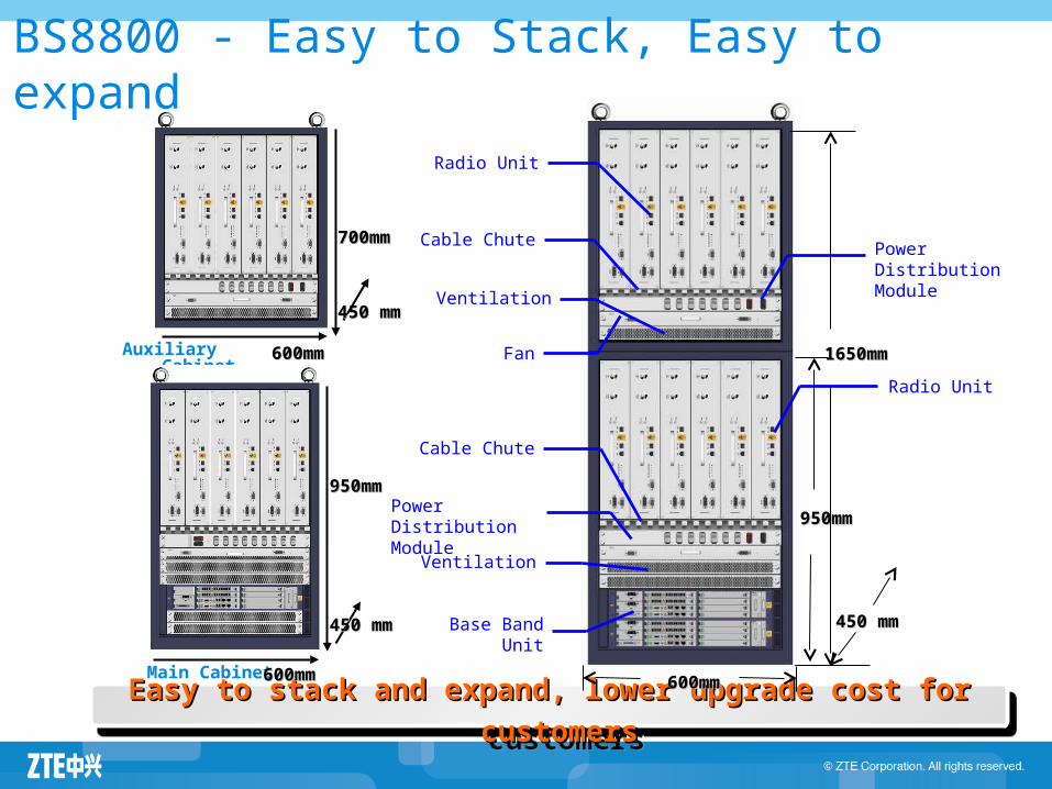
Easy to stack and expand, lower upgrade cost for customersEasy to stack and expand, lower upgrade cost for customersEasy to stack and expand, lower upgrade cost for customersEasy to stack and expand, lower upgrade cost for customers
BS8800 - Easy to Stack, Easy to expand
1650mm1650mm
450 mm450 mm
600mm600mm
Power DistributionModule
Cable Chute
Base Band Unit
950mm950mmPower DistributionModule
Cable Chute
Radio Unit
Auxiliary Cabinet Fan
Radio Unit
Ventilation
Main Cabinet
950mm950mm
600mm600mm
450 mm450 mm
600mm600mm
450 mm450 mm
700mm700mm
Ventilation
Agenda
ZXSDR BTS Family Introduction ZXSDR BS8700 ZXSDR BS8800 ZXSDR BS8900 ZXSDR BS8906 ZXSDR BTS Work Principle ZXSDR BTS Operation and Maintenance
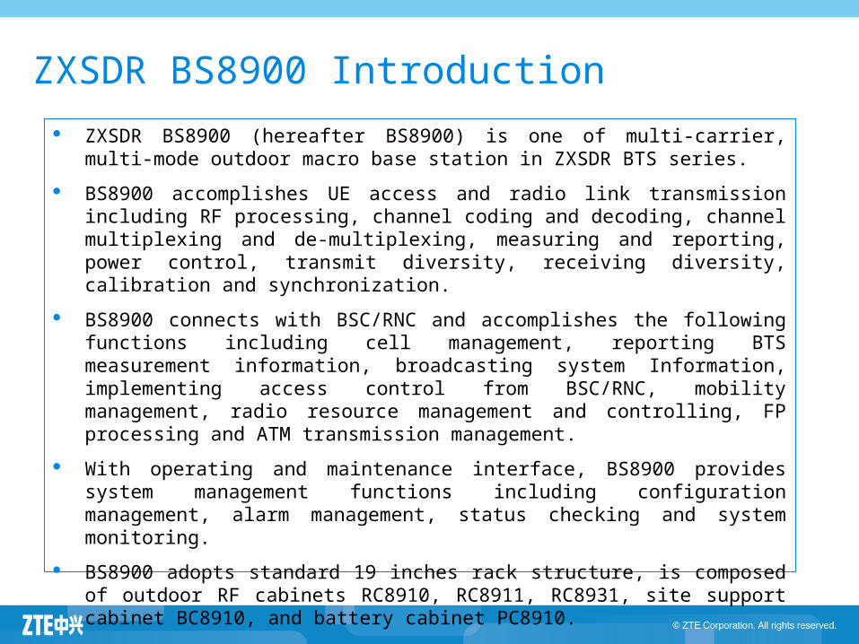
ZXSDR BS8900 Introduction
ZXSDR BS8900 (hereafter BS8900) is one of multi-carrier, multi-mode outdoor macro base station in ZXSDR BTS series.
BS8900 accomplishes UE access and radio link transmission including RF processing, channel coding and decoding, channel multiplexing and de-multiplexing, measuring and reporting, power control, transmit diversity, receiving diversity, calibration and synchronization.
BS8900 connects with BSC/RNC and accomplishes the following functions including cell management, reporting BTS measurement information, broadcasting system Information, implementing access control from BSC/RNC, mobility management, radio resource management and controlling, FP processing and ATM transmission management.
With operating and maintenance interface, BS8900 provides system management functions including configuration management, alarm management, status checking and system monitoring.
BS8900 adopts standard 19 inches rack structure, is composed of outdoor RF cabinets RC8910, RC8911, RC8931, site support cabinet BC8910, and battery cabinet PC8910.
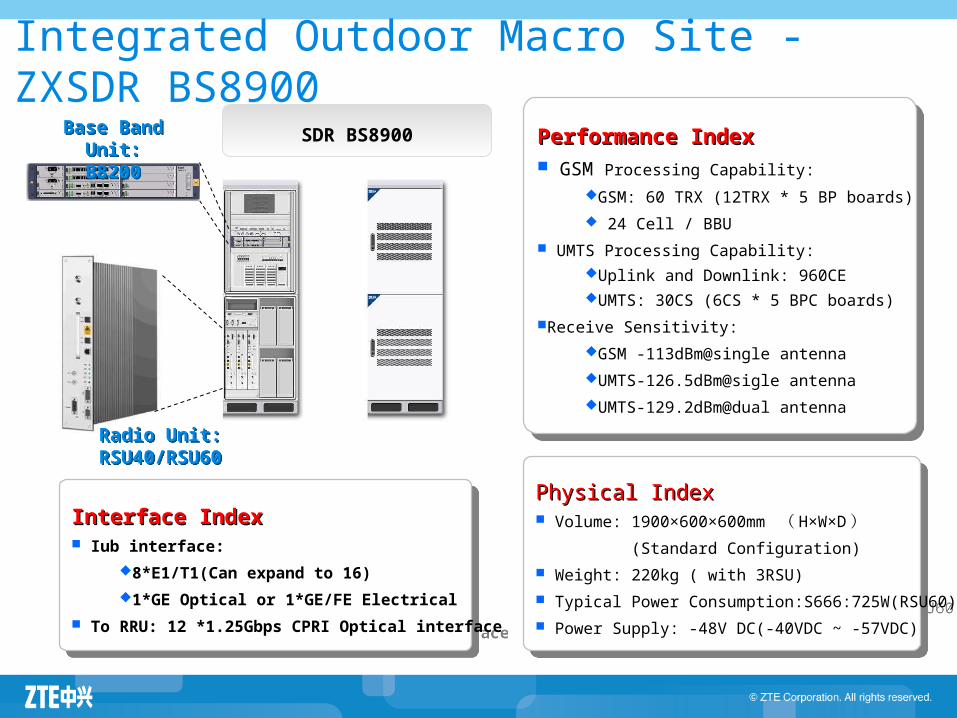
Integrated Outdoor Macro Site - ZXSDR BS8900
Radio Unit:RSU40/RSU60
Radio Unit:RSU40/RSU60
Physical IndexPhysical Index Volume: 1900×600×600mm ( H×W×D )
(Standard Configuration)
Weight: 220kg ( with 3RSU)
Typical Power Consumption:S666:725W(RSU60)
Power Supply: -48V DC(-40VDC ~ -57VDC)
Physical IndexPhysical Index Volume: 1900×600×600mm ( H×W×D )
(Standard Configuration)
Weight: 220kg ( with 3RSU)
Typical Power Consumption:S666:725W(RSU60)
Power Supply: -48V DC(-40VDC ~ -57VDC)
Interface IndexInterface Index Iub interface:
8*E1/T1(Can expand to 16)
1*GE Optical or 1*GE/FE Electrical
To RRU: 12 *1.25Gbps CPRI Optical interface
Interface IndexInterface Index Iub interface:
8*E1/T1(Can expand to 16)
1*GE Optical or 1*GE/FE Electrical
To RRU: 12 *1.25Gbps CPRI Optical interface
SDR BS8900Base Band Unit:B8200
Base Band Unit:B8200 Performance IndexPerformance Index
GSM Processing Capability:
GSM: 60 TRX (12TRX * 5 BP boards)
24 Cell / BBU
UMTS Processing Capability:Uplink and Downlink: 960CEUMTS: 30CS (6CS * 5 BPC boards)
Receive Sensitivity:
GSM -113dBm@single antenna
UMTS-126.5dBm@sigle antenna
UMTS-129.2dBm@dual antenna
Performance IndexPerformance Index GSM Processing Capability:
GSM: 60 TRX (12TRX * 5 BP boards)
24 Cell / BBU
UMTS Processing Capability:Uplink and Downlink: 960CEUMTS: 30CS (6CS * 5 BPC boards)
Receive Sensitivity:
GSM -113dBm@single antenna
UMTS-126.5dBm@sigle antenna
UMTS-129.2dBm@dual antenna
43
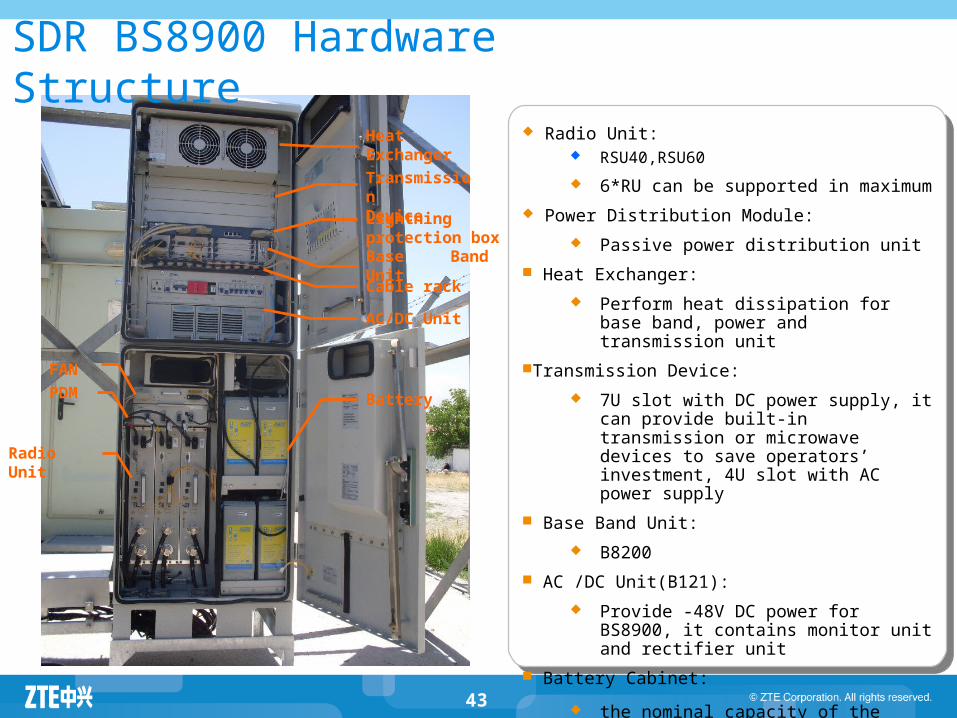
SDR BS8900 Hardware Structure Radio Unit:
RSU40,RSU60
6*RU can be supported in maximum
Power Distribution Module:
Passive power distribution unit
Heat Exchanger:
Perform heat dissipation for base band, power and transmission unit
Transmission Device:
7U slot with DC power supply, it can provide built-in transmission or microwave devices to save operators’ investment, 4U slot with AC power supply
Base Band Unit:
B8200
AC /DC Unit(B121):
Provide -48V DC power for BS8900, it contains monitor unit and rectifier unit
Battery Cabinet:
the nominal capacity of the built-in batteries
is 300Ah
Heat Exchanger
TransmissionDevice
Base Band Unit
AC/DC Unit
PDM
Lightning protection box
Cable rack
FAN
Battery
Radio Unit
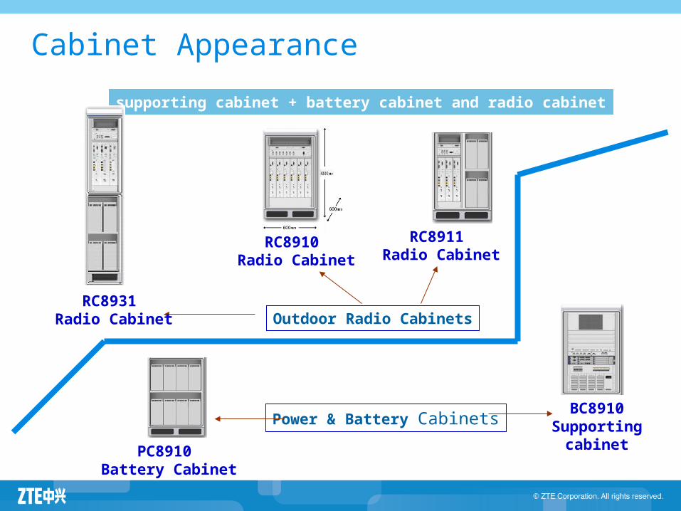
Cabinet Appearance
supporting cabinet + battery cabinet and radio cabinet
Outdoor Radio Cabinets
RC8910 Radio Cabinet
BC8910Supporting
cabinetPC8910 Battery Cabinet
Power & Battery Cabinets
RC8931 Radio Cabinet
RC8911 Radio Cabinet
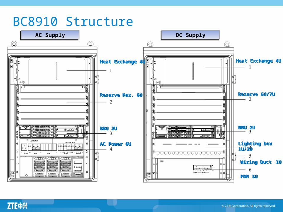
BC8910 Structure
Heat Exchange 4UHeat Exchange 4U
Reserve Max. 6UReserve Max. 6U
BBU 2UBBU 2U
AC Power 6UAC Power 6U
Heat Exchange 4UHeat Exchange 4U
Reserve 6U/7UReserve 6U/7U
BBU 2UBBU 2U
PDM 3UPDM 3U
Lighting box 1U/2ULighting box 1U/2U
Wiring Duct 1UWiring Duct 1U
AC SupplyAC Supply DC SupplyDC Supply
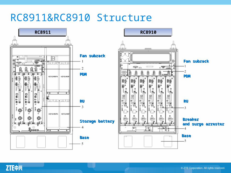
RC8911&RC8910 Structure
RURU
Fan subrackFan subrack
PDMPDM
Storage batteryStorage battery
BaseBase
Fan subrackFan subrack
PDMPDM
Breakerand surge arresterBreakerand surge arrester
RURU
BaseBase
RC8911RC8911 RC8910RC8910
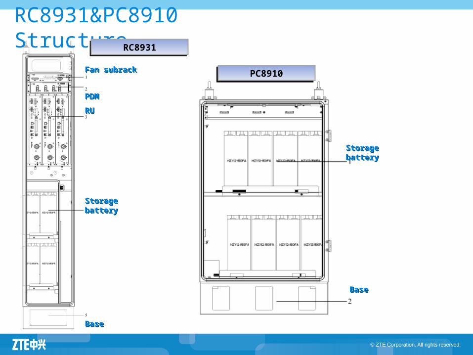
RC8931&PC8910 Structure
RURU
Fan subrackFan subrack
Storage batteryStorage battery
BaseBase
PDMPDM
BaseBase
Storage batteryStorage battery
RC8931RC8931
PC8910PC8910
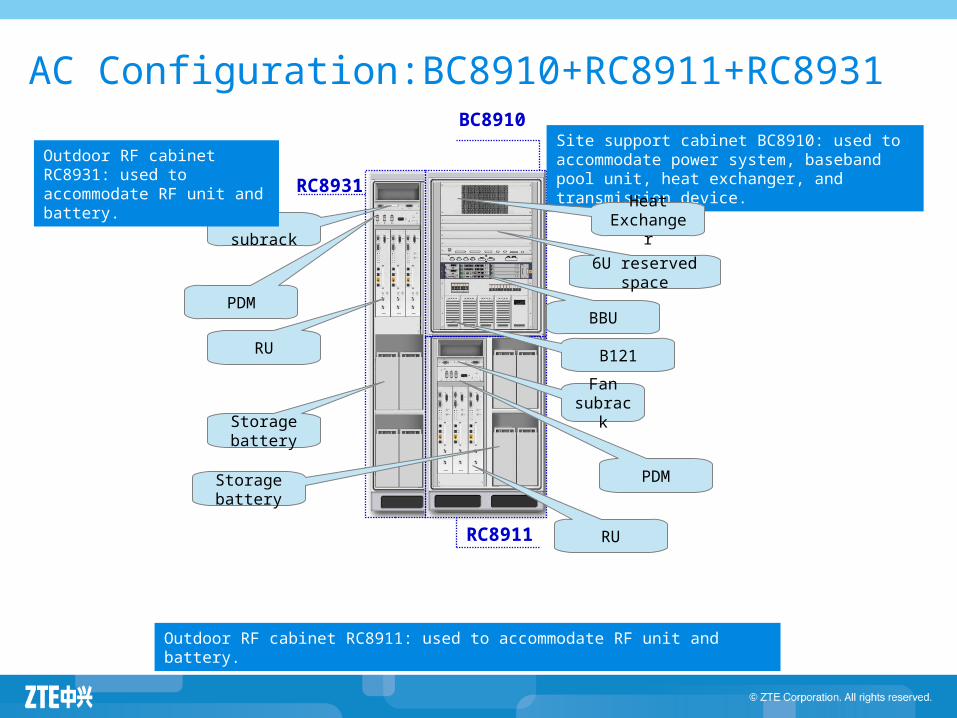
AC Configuration:BC8910+RC8911+RC8931
Fan subrack
BC8910
RC8911
RC8931
Site support cabinet BC8910: used to accommodate power system, baseband pool unit, heat exchanger, and transmission device.
Outdoor RF cabinet RC8911: used to accommodate RF unit and battery.
Outdoor RF cabinet RC8931: used to accommodate RF unit and battery.
Heat Exchanger
BBU
B121
Fan subrack
PDM
RU
Storage battery
PDM
RU
Storage battery
6U reserved space
RC8910
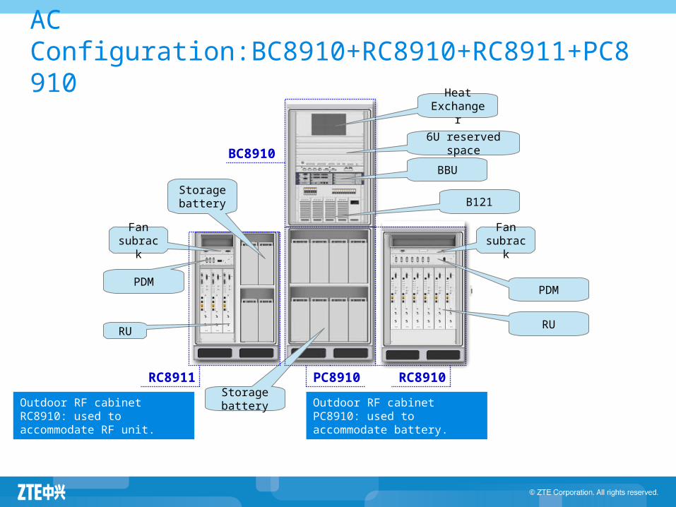
AC Configuration:BC8910+RC8910+RC8911+PC8910
PC8910
BC8910
Heat Exchanger
BBU
B121
Fan subrack
PDM
RU
Storage battery
Fan subrack
PDM
RU
6U reserved space
RC8911
Outdoor RF cabinet RC8910: used to accommodate RF unit.
Outdoor RF cabinet PC8910: used to accommodate battery.
Storage battery
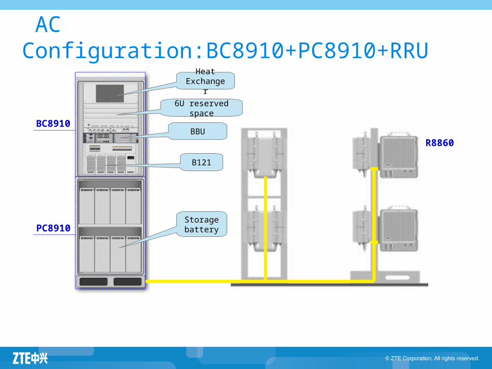
AC Configuration:BC8910+PC8910+RRU
PC8910
BC8910
R8860
Heat Exchanger
6U reserved space
BBU
B121
Storage battery
BC8910
RC8910
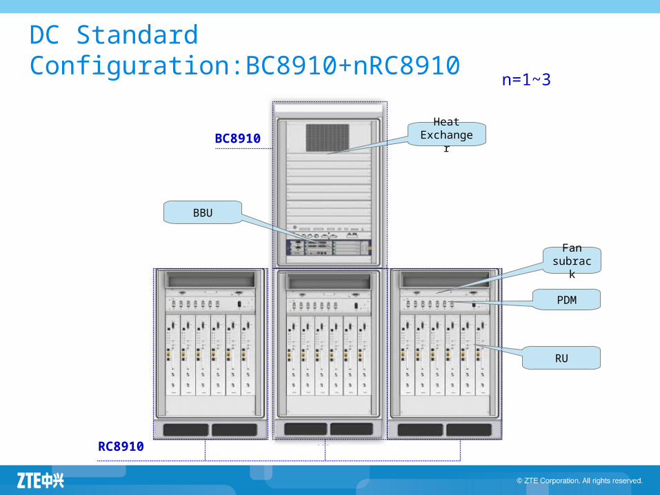
DC Standard Configuration:BC8910+nRC8910
BBU
Heat Exchanger
RU
PDM
Fan subrack
n=1~3
52
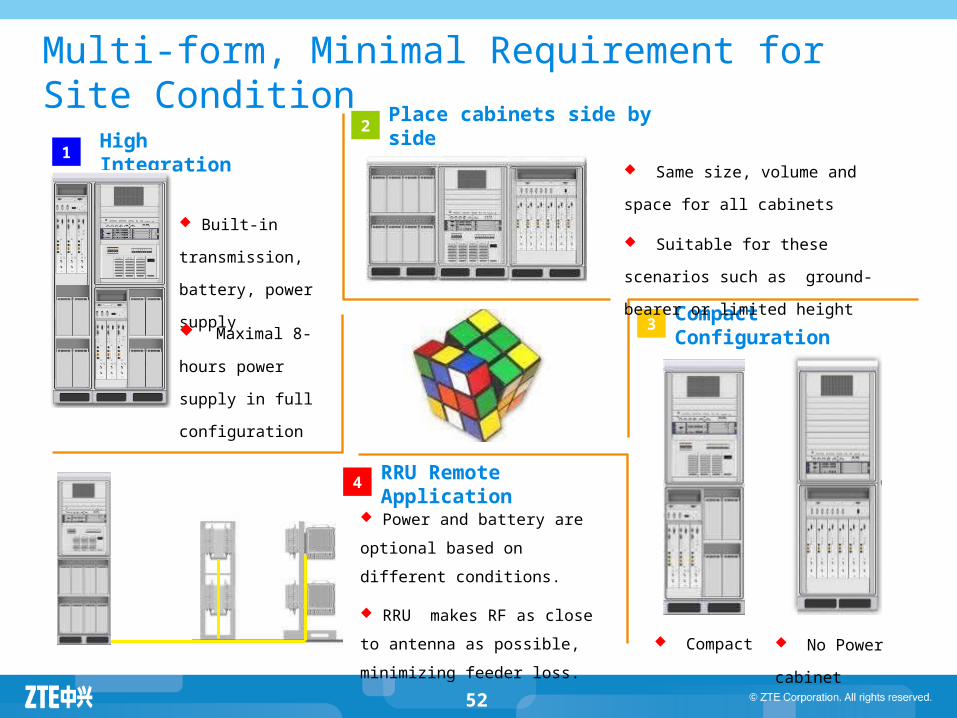
Multi-form, Minimal Requirement for Site Condition2
3
4
1
Place cabinets side by side
RRU Remote Application
Compact Configuration
High Integration
Built-in transmission,
battery, power supply
Maximal 8-hours
power supply in full
configuration
Same size, volume and space for
all cabinets
Suitable for these scenarios such as
ground-bearer or limited height
No Power cabinet Compact
Power and battery are optional
based on different conditions.
RRU makes RF as close to
antenna as possible, minimizing
feeder loss.
Agenda
ZXSDR BTS Family Introduction ZXSDR BS8700 ZXSDR BS8800 ZXSDR BS8900 ZXSDR BS8906 ZXSDR BTS Work Principle ZXSDR BTS Operation and Maintenance
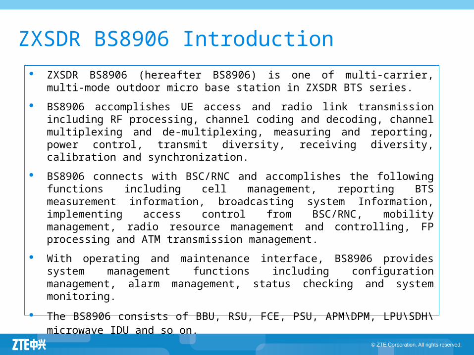
ZXSDR BS8906 Introduction
ZXSDR BS8906 (hereafter BS8906) is one of multi-carrier, multi-mode outdoor micro base station in ZXSDR BTS series.
BS8906 accomplishes UE access and radio link transmission including RF processing, channel coding and decoding, channel multiplexing and de-multiplexing, measuring and reporting, power control, transmit diversity, receiving diversity, calibration and synchronization.
BS8906 connects with BSC/RNC and accomplishes the following functions including cell management, reporting BTS measurement information, broadcasting system Information, implementing access control from BSC/RNC, mobility management, radio resource management and controlling, FP processing and ATM transmission management.
With operating and maintenance interface, BS8906 provides system management functions including configuration management, alarm management, status checking and system monitoring.
The BS8906 consists of BBU, RSU, FCE, PSU, APM\DPM, LPU\SDH\microwave IDU and so on.
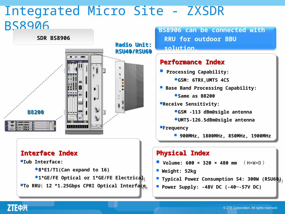
Integrated Micro Site - ZXSDR BS8906
Radio Unit:RSU40/RSU60
Radio Unit:RSU40/RSU60
Physical IndexPhysical Index Volume: 600 × 320 × 480 mm ( H×W×D ) Weight: 52kg
Typical Power Consumption S4: 300W (RSU60)
Power Supply: -48V DC (-40~-57V DC)
Physical IndexPhysical Index Volume: 600 × 320 × 480 mm ( H×W×D ) Weight: 52kg
Typical Power Consumption S4: 300W (RSU60)
Power Supply: -48V DC (-40~-57V DC)
Performance IndexPerformance Index Processing Capability:
GSM: 6TRX,UMTS 4CS
Base Band Processing Capability:
Same as B8200
Receive Sensitivity:
GSM -113 dBm@sigle antenna
UMTS-126.5dBm@sigle antenna
Frequency
900MHz, 1800MHz, 850MHz, 1900MHz
Performance IndexPerformance Index Processing Capability:
GSM: 6TRX,UMTS 4CS
Base Band Processing Capability:
Same as B8200
Receive Sensitivity:
GSM -113 dBm@sigle antenna
UMTS-126.5dBm@sigle antenna
Frequency
900MHz, 1800MHz, 850MHz, 1900MHz
Interface IndexInterface IndexIub Interface:
8*E1/T1(Can expand to 16)
1*GE/FE Optical or 1*GE/FE Electrical
To RRU: 12 *1.25Gbps CPRI Optical Interface
Interface IndexInterface IndexIub Interface:
8*E1/T1(Can expand to 16)
1*GE/FE Optical or 1*GE/FE Electrical
To RRU: 12 *1.25Gbps CPRI Optical Interface
SDR BS8906
B8200B8200
BS8906 can be connected with RRU
for outdoor BBU solution.
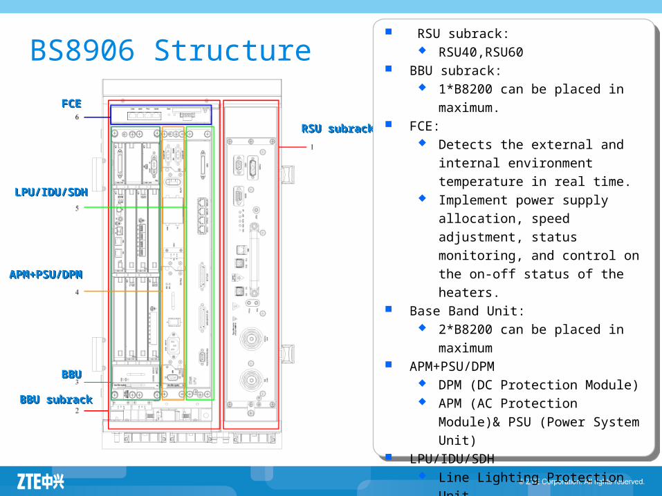
BS8906 Structure
FCEFCE
RSU subrackRSU subrack
LPU/IDU/SDHLPU/IDU/SDH
APM+PSU/DPMAPM+PSU/DPM
BBU subrackBBU subrack
BBUBBU
RSU subrack: RSU40,RSU60
BBU subrack: 1*B8200 can be placed in
maximum. FCE:
Detects the external and internal
environment temperature in real
time. Implement power supply allocation,
speed adjustment, status
monitoring, and control on the on-
off status of the heaters. Base Band Unit:
2*B8200 can be placed in
maximum APM+PSU/DPM
DPM (DC Protection Module) APM (AC Protection Module)&
PSU (Power System Unit) LPU/IDU/SDH
Line Lighting Protection Unit SDH/Microwave IDU
Agenda
ZXSDR BTS Family Introduction ZXSDR BS8700 ZXSDR BS8800 ZXSDR BS8900 ZXSDR BS8906 ZXSDR BTS Work Principle ZXSDR BTS Operation and Maintenance
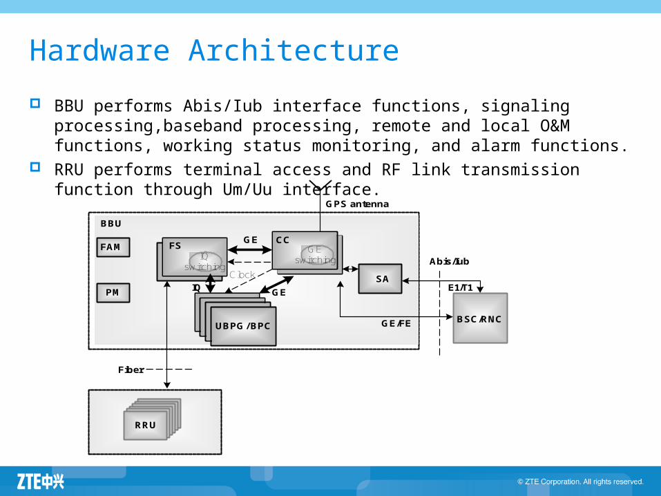
Hardware Architecture
BBU performs Abis/Iub interface functions, signaling processing,baseband processing, remote and local O&M functions, working status monitoring, and alarm functions.
RRU performs terminal access and RF link transmission function through Um/Uu interface.
GPS antenna
SAE1/T1
BSC/RNC
IQ switching
IQ GE
RRU
FAM
PM
Abis/Iub
Clock
GE/FE
GE
UBPG/ BPC
FS GEswitching
CC
Fiber
BBU
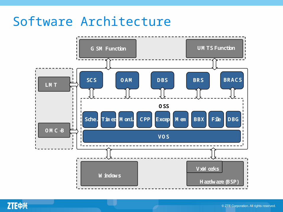
Software Architecture
OSS
G SM Function
UMTS Function
NOP
OMC-B
SCS OAM DBS BRACS BRS
VOS
Sche. Timer Moni. CPP Excep Mem BBX File DBG
Windows
Hardware (BSP)
VxWorks
LMT
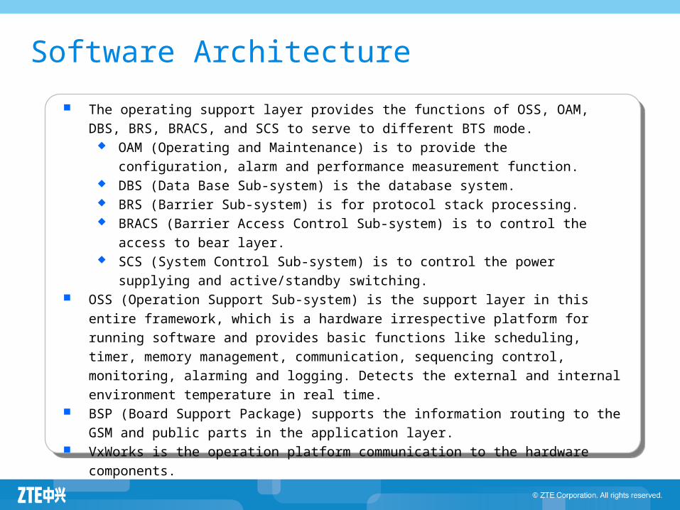
The operating support layer provides the functions of OSS, OAM, DBS, BRS, BRACS, and
SCS to serve to different BTS mode. OAM (Operating and Maintenance) is to provide the configuration, alarm and
performance measurement function. DBS (Data Base Sub-system) is the database system. BRS (Barrier Sub-system) is for protocol stack processing. BRACS (Barrier Access Control Sub-system) is to control the access to bear layer. SCS (System Control Sub-system) is to control the power supplying and
active/standby switching. OSS (Operation Support Sub-system) is the support layer in this entire framework, which
is a hardware irrespective platform for running software and provides basic functions like
scheduling, timer, memory management, communication, sequencing control, monitoring,
alarming and logging. Detects the external and internal environment temperature in real
time. BSP (Board Support Package) supports the information routing to the GSM and public
parts in the application layer. VxWorks is the operation platform communication to the hardware components.
Software Architecture
Agenda
ZXSDR BTS Family Introduction ZXSDR BS8700 ZXSDR BS8800 ZXSDR BS8900 ZXSDR BS8906 ZXSDR BTS Work Principle ZXSDR BTS Operation and Maintenance
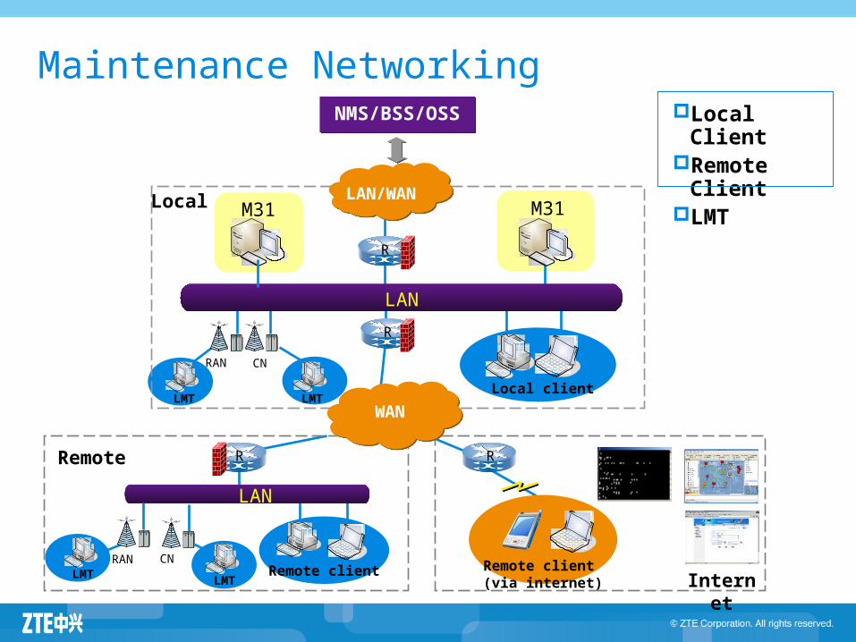
Maintenance NetworkingNMS/BSS/OSSNMS/BSS/OSS
Local LAN/WANLAN/WAN
LAN
R
R
M31
Remote
Remote client
LAN
R
RAN
RAN
M31
Remote client (via internet)
R
WANWAN
Internet
Local ClientRemote
ClientLMT
Local clientLMT LMT
LMTLMT
CN
CN
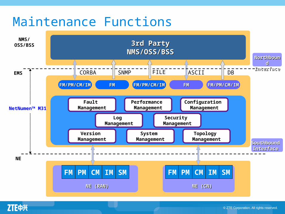
Maintenance Functions
Fault Management
NE (RAN)NE (RAN)
3rd Party NMS/OSS/BSS
3rd Party NMS/OSS/BSS
CORBA SNMP FILE ASCII DB
Performance Management
Configuration Management
Log Management
Security Management
NorthboundInterface
NorthboundInterface
Version Management
System Management
Topology Management
FM
NE (CN)NE (CN)
SouthboundInterface
SouthboundInterface
PM CM IM SM
NE
EMS
NMS/OSS/BSS
NetNumenTM M31
FMFM FM/PM/CM/IMFM/PM/CM/IMFM/PM/CM/IMFM/PM/CM/IM FMFM FM/PM/CM/IMFM/PM/CM/IM
FM PM CM IM SM
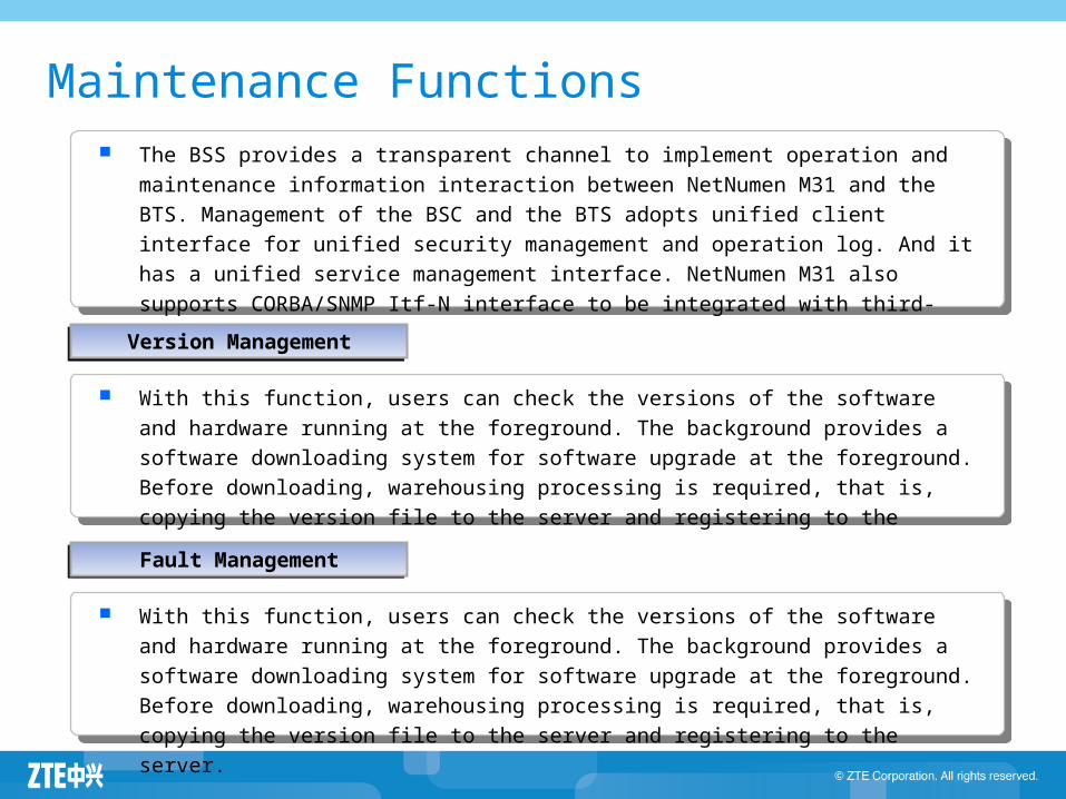
The BSS provides a transparent channel to implement operation and maintenance
information interaction between NetNumen M31 and the BTS. Management of the BSC
and the BTS adopts unified client interface for unified security management and operation
log. And it has a unified service management interface. NetNumen M31 also supports
CORBA/SNMP Itf-N interface to be integrated with third-part NMS.
Maintenance Functions
Version ManagementVersion Management
With this function, users can check the versions of the software and hardware running at
the foreground. The background provides a software downloading system for software
upgrade at the foreground. Before downloading, warehousing processing is required, that
is, copying the version file to the server and registering to the server.
Fault ManagementFault Management
With this function, users can check the versions of the software and hardware running at
the foreground. The background provides a software downloading system for software
upgrade at the foreground. Before downloading, warehousing processing is required, that
is, copying the version file to the server and registering to the server.
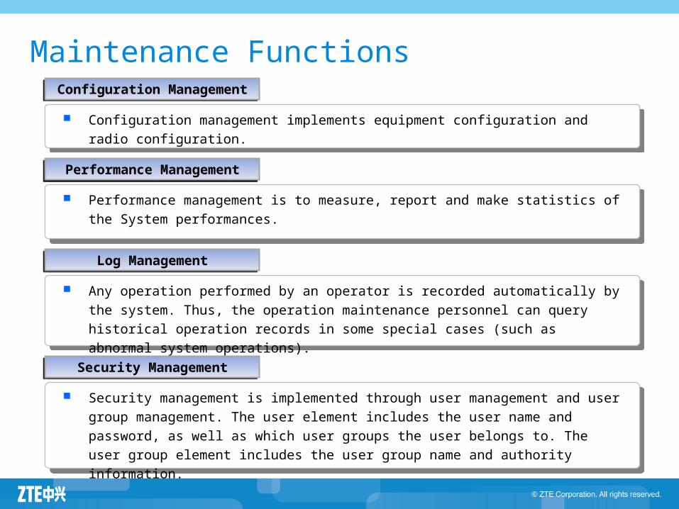
Maintenance FunctionsConfiguration
ManagementConfiguration
Management
Configuration management implements equipment configuration and radio configuration.
Log ManagementLog Management
Any operation performed by an operator is recorded automatically by the system. Thus,
the operation maintenance personnel can query historical operation records in some
special cases (such as abnormal system operations).
Security ManagementSecurity Management
Security management is implemented through user management and user group
management. The user element includes the user name and password, as well as which
user groups the user belongs to. The user group element includes the user group name
and authority information.
Performance ManagementPerformance Management
Performance management is to measure, report and make statistics of the System
performances.


![SJ-20100510160815-010-ZXSDR BTS&Node B (V4[1].09.21) LMT Operation Guide](https://img.pdfslide.us/doc/110x75/577ccd441a28ab9e788bf3a3/sj-20100510160815-010-zxsdr-btsnode-b-v410921-lmt-operation-guide.jpg)