Embed Size (px)
Citation preview
BLN-0014June 2009
ZT-5400 Powertrain™Service and Repair Manual
ZT-5400 Powertrain i
Foreword . . . . . . . . . . . . . . . . . . . . . . . . . . . . . . . . . . .1
Description and Operation . . . . . . . . . . . . . . . . . . . . .2
Introduction . . . . . . . . . . . . . . . . . . . . . . . . . . . . . . . . .2
Hydraulic Schematic . . . . . . . . . . . . . . . . . . . . . . . . . .3
External Features . . . . . . . . . . . . . . . . . . . . . . . . . . 4-5
Technical Specifications . . . . . . . . . . . . . . . . . . . . . . .6
Product Identification . . . . . . . . . . . . . . . . . . . . . . . . . .6
Safety . . . . . . . . . . . . . . . . . . . . . . . . . . . . . . . . . . . . .7
Personal Safety . . . . . . . . . . . . . . . . . . . . . . . . . . . . . .7
Tool Safety. . . . . . . . . . . . . . . . . . . . . . . . . . . . . . . . . .7
Work Area Safety . . . . . . . . . . . . . . . . . . . . . . . . . . . .7
Servicing Safety . . . . . . . . . . . . . . . . . . . . . . . . . . . . .7
Troubleshooting . . . . . . . . . . . . . . . . . . . . . . . . . . . . . .8
Service and Maintenance . . . . . . . . . . . . . . . . . . . . . .9
External Maintenance . . . . . . . . . . . . . . . . . . . . . . . . .9
Service and Maintenance Procedures . . . . . . . . . . . .9
Fluids . . . . . . . . . . . . . . . . . . . . . . . . . . . . . . . . . . . . . .9
Fluid Volume and Level . . . . . . . . . . . . . . . . . . . . . . . .9
Fluid Change Procedure . . . . . . . . . . . . . . . . . . . . . .10
Purging Procedures . . . . . . . . . . . . . . . . . . . . . . . . . .11
Return To Neutral Setting . . . . . . . . . . . . . . . . . . . . .12
2-Speed Option Settings . . . . . . . . . . . . . . . . . . . . . .13
Tear Down and Reassembly . . . . . . . . . . . . . . . . . . .14
How to Use This Manual . . . . . . . . . . . . . . . . . . . . . .14
General Instructions . . . . . . . . . . . . . . . . . . . . . . . . .14
Tools . . . . . . . . . . . . . . . . . . . . . . . . . . . . . . . . . . . . .15
Torques . . . . . . . . . . . . . . . . . . . . . . . . . . . . . . . . . . .15
Transaxle Removal . . . . . . . . . . . . . . . . . . . . . . . . . .16
Fan and Pulley . . . . . . . . . . . . . . . . . . . . . . . . . . . . . .17
Axle Hub Assembly . . . . . . . . . . . . . . . . . . . . . . . . . .17
Return to Neutral Assembly Option . . . . . . . . . . . . . .18
Control Arm Assembly . . . . . . . . . . . . . . . . . . . . . . .19
Filter And Filter Cover . . . . . . . . . . . . . . . . . . . . . . . .20
Brake Assembly . . . . . . . . . . . . . . . . . . . . . . . . . . . .21
2-Speed Arm . . . . . . . . . . . . . . . . . . . . . . . . . . . . . . .22
Bypass Actuator . . . . . . . . . . . . . . . . . . . . . . . . . . . .23
Side Housing . . . . . . . . . . . . . . . . . . . . . . . . . . . . . . .24
Axle Shaft And Planetary Gear Set . . . . . . . . . . . . .25
Charge Pump And Oil Tube . . . . . . . . . . . . . . . . . . .26
Input Shaft . . . . . . . . . . . . . . . . . . . . . . . . . . . . . . . . .27
Swashplate . . . . . . . . . . . . . . . . . . . . . . . . . . . . . . . .28
Center Section . . . . . . . . . . . . . . . . . . . . . . . . . . . . . .29
Brake Assembly And Motor Shaft . . . . . . . . . . . . . . .30
Motor Cyl Block, 2-Speed Shaft & Swashplate . . . . .31
Center Section And Magnet . . . . . . . . . . . . . . . . . . .32
Assembly After A Complete Teardown . . . . . . . . 33-34
Screw Tightening Sequence . . . . . . . . . . . . . . . . . . .35
ZT-5400 Powertrain Exploded View . . . . . . . . . 36-37
Glossary of Terms . . . . . . . . . . . . . . . . . . . . . . . . 38-39
Notes . . . . . . . . . . . . . . . . . . . . . . . . . . . . . . . . . . 40-41
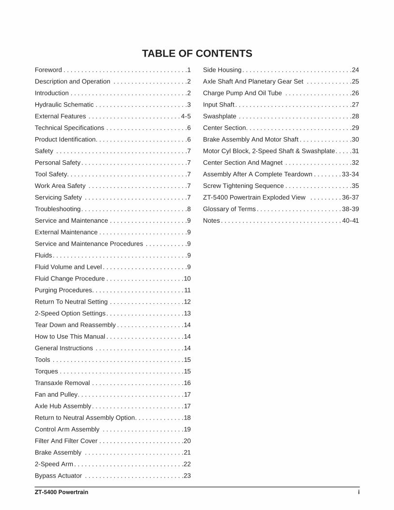
TABLE OF CONTENTS
ZT-5400 Powertrain 1
FOREWORD
Headquar te red in Su l l i van , I l l i no is ,Hydro-Gear is a world leader in the design, manufacture, and service of quality hydrostatic transaxles for the lawn and garden industry. The mission of our company is to be recog-nized by our customers and the industry as a world-class supplier and the quality leader in everything we do.
This Service and Repair Manual is designed to provide information useful in servicing and troubleshooting the Hydro-Gear® ZT-5400 Powertrain.™
Also included is a glossary of terms that are frequently used throughout the industry and in Hydro-Gear service publications. Understand-ing terminology is very important!
It is necessary, and a good shop practice, that your service area be equipped with the proper tools and the mechanics be supplied the latest information available. All repair procedures illustrated in this guide are suggested, but pre-ferred methods of repair.
Internal repair procedures require that the transaxle unit be removed from the vehicle.
This is not a certifi cation, test or study guide for a certifi cation test. If a technician is interested in certifi cation, they should contact an agent representing the EETC (Equipment and Engine Training Council) at (262) 367-6700 or their Hydro-Gear Central Service Distributor. Many distributors will be hosting certifi cation testing. These study guides will cover most of the prod-ucts and manufacturers in our industry.
For more information about Hydro-Gear or our products, please contact your Central Service Distributor, or call our Customer Service Depart-ment at (217) 728-2581.
2 ZT-5400 Powertrain
The ZT-5400 Powertrain has a self contained fl uid supply and an internal fi lter. The fl uid is forced through the fi lter by a positive “head” on the fl uid in the housing/expansion tank with an assist by the negative pressure created in the pump pistons as they operate.
The check valves in the center section are used to control the makeup fl ow of the fl uid to the low pressure side of the loop.
A hydraulic bypass is utilized in the ZT-5400 Powertrain to permit moving the vehicle for a short distance at a maximum of 2 m.p.h. (3.2 Km/h) without starting the engine.
The ZT-5400 Powertrain utilizes an internal in-line fl oating disc brake controlled by a “cam” style actuating arm.
INTRODUCTIONThe purpose of this manual is to provide in-formation useful in servicing the Hydro-Gear® ZT-5400 Powertrain™ Hydrostatic Transaxle. This manual includes the ZT-5400 Powertrain’s general description, hydraulic schematic, tech-nical specifi cations, servicing and troubleshoot-ing procedures.
Should servicing be required, the exterior of the transaxle will need to be thoroughly cleaned before beginning most procedures. Do not wash the transaxle while it is hot. Do not use a pressure washer to clean the unit.
GENERAL DESCRIPTIONThe ZT-5400 Powertrain is a self contained unit designed for the transfer and control of power. It provides an infi nitely variable speed range between zero and maximum in both forward and reverse modes of operation.
This transaxle uses a variable displacement pump with a maximum displacement of 16.4cc per revolution, and the motor has two distinct displacement of 28.1cc and 15.0cc per revolu-tion. The variable displacement pump features a trunnion mounted swashplate with a direct-proportional displacement control. Reversing the direction of the swashplate reverses the fl ow of oil from the pump and thus reverses the direction of the motor output rotation. The pump and motor are of the axial piston design and utilize spherical nosed pistons which are held against a thrust race by internal compres-sion springs.
DESCRIPTION AND OPERATION
ZT-5400 Powertrain 3
FILTER
CHARGE PUMP
CHARGERELIEFVALVE
PUMP
BYPASS
MOTOR
MOTOROUTPUTSHAFT
SYSTEM CHECK VALVEWITH RELIEF
EXPANSION/RESERVOIR TANKVENT
PUMP INPUTSHAFT
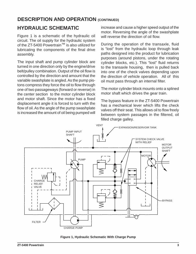
Figure 1, Hydraulic Schematic With Charge Pump
DESCRIPTION AND OPERATION (CONTINUED)
HYDRAULIC SCHEMATICFigure 1 is a schematic of the hydraulic oil circuit. The oil supply for the hydraulic system of the ZT-5400 Powertrain™ is also utilized for lubricating the components of the fi nal drive assembly.
The input shaft and pump cylinder block are turned in one direction only by the engine/drive belt/pulley combination. Output of the oil fl ow is controlled by the direction and amount that the variable swashplate is angled. As the pump pis-tons compress they force the oil to fl ow through one of two passageways (forward or reverse) in the center section to the motor cylinder block and motor shaft. Since the motor has a fi xed displacement angle it is forced to turn with the fl ow of oil. As the angle of the pump swashplate is increased the amount of oil being pumped will
increase and cause a higher speed output of the motor. Reversing the angle of the swashplate will reverse the direction of oil fl ow.
During the operation of the transaxle, fl uid is “lost” from the hydraulic loop through leak paths designed into the product for lubrication purposes (around pistons, under the rotating cylinder blocks, etc.). This “lost” fl uid returns to the transaxle housing, then is pulled back into one of the check valves depending upon the direction of vehicle operation. All of this oil must pass through an internal fi lter.
The motor cylinder block mounts onto a splined motor shaft which drives the gear train.
The bypass feature in the ZT-5400 Powertrain has a mechanical lever which lifts the check valves off their seat. This allows oil to fl ow freely between system passages in the fi ltered, oil fi lled charge galley.
4 ZT-5400 Powertrain
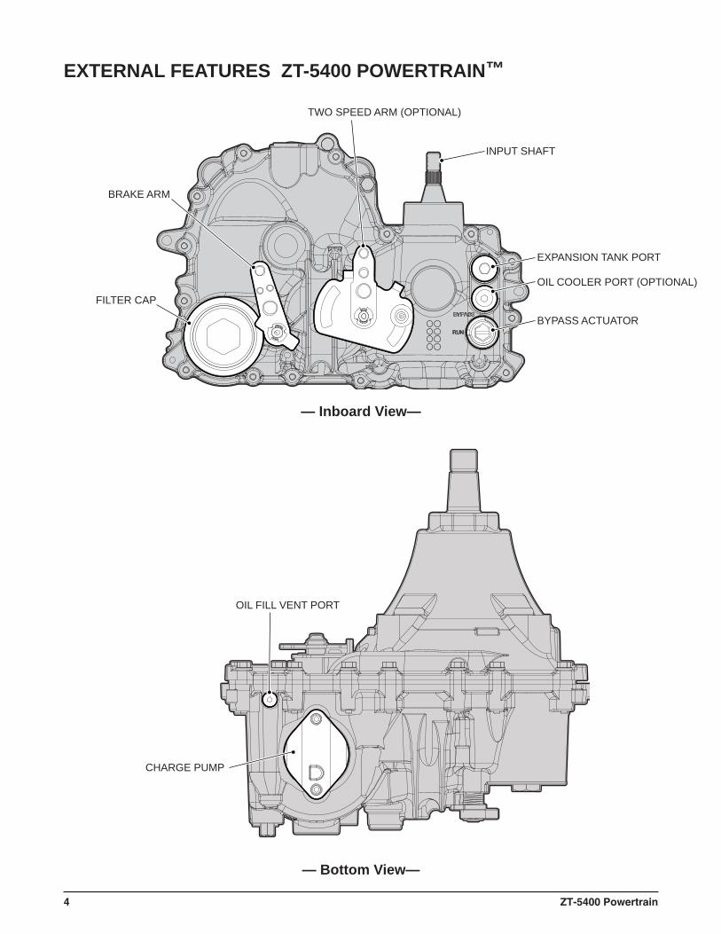
INPUT SHAFT
BRAKE ARM
FILTER CAP
EXPANSION TANK PORT
OIL COOLER PORT (OPTIONAL)
BYPASS ACTUATOR
TWO SPEED ARM (OPTIONAL)
OIL FILL VENT PORT
CHARGE PUMP
— Bottom View—
EXTERNAL FEATURES ZT-5400 POWERTRAIN™
— Inboard View—
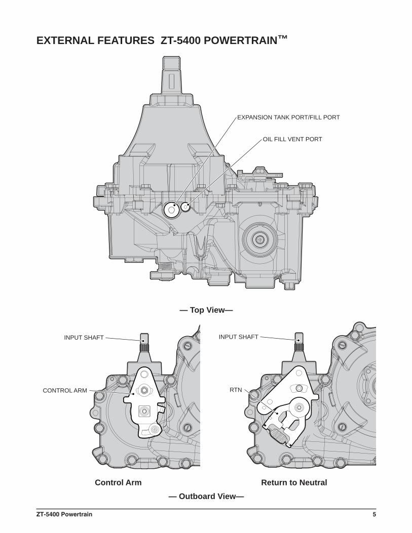
ZT-5400 Powertrain 5
INPUT SHAFT
CONTROL ARM
EXPANSION TANK PORT/FILL PORT
OIL FILL VENT PORT
INPUT SHAFT
RTN
EXTERNAL FEATURES ZT-5400 POWERTRAIN™
— Top View—
— Outboard View—Control Arm Return to Neutral
6 ZT-5400 Powertrain
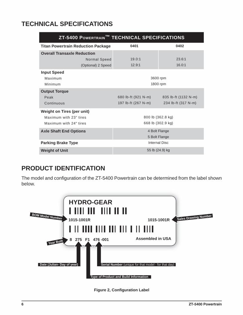
HYDRO-GEAR
Assembled in USAYear Built
1015-1001R 1015-1001R
8 275 F1 476 -001
BOM Model Number
Date (Julian- Day of year) Serial Number (unique for that model - for that day)
Type of Product and Build Information
Sales Drawing Number
ZT-5400 POWERTRAIN™ TECHNICAL SPECIFICATIONSTitan Powertrain Reduction Package 0401 0402
Overall Transaxle ReductionNormal Speed
(Optional) 2 Speed
19.0:112.9:1
23.6:116.0:1
Input SpeedMaximumMinimum
3600 rpm1800 rpm
Output TorquePeakContinuous
680 lb-ft (921 N-m)197 lb-ft (267 N-m)
835 lb-ft (1132 N-m)234 lb-ft (317 N-m)
Weight on Tires (per unit)Maximum with 23” tiresMaximum with 24” tires
800 lb (362.8 kg)668 lb (302.9 kg)
Axle Shaft End Options 4 Bolt Flange5 Bolt Flange
Parking Brake Type Internal Disc
Weight of Unit 55 lb (24.9) kg
Figure 2, Confi guration Label
PRODUCT IDENTIFICATIONThe model and confi guration of the ZT-5400 Powertrain can be determined from the label shown below.
TECHNICAL SPECIFICATIONS
ZT-5400 Powertrain 7
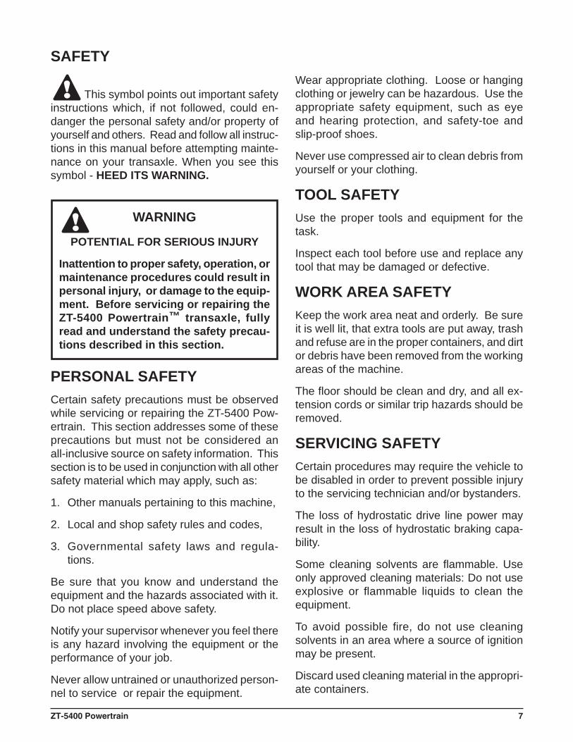
This symbol points out important safety instructions which, if not followed, could en-danger the personal safety and/or property of yourself and others. Read and follow all instruc-tions in this manual before attempting mainte-nance on your transaxle. When you see this symbol - HEED ITS WARNING.
WARNING
POTENTIAL FOR SERIOUS INJURY
Inattention to proper safety, operation, or maintenance procedures could result in personal injury, or damage to the equip-ment. Before servicing or repairing the ZT-5400 Powertrain™ transaxle, fully read and understand the safety precau-tions described in this section.
PERSONAL SAFETYCertain safety precautions must be observed while servicing or repairing the ZT-5400 Pow-ertrain. This section addresses some of these precautions but must not be considered an all-inclusive source on safety information. This section is to be used in conjunction with all other safety material which may apply, such as:
1. Other manuals pertaining to this machine,
2. Local and shop safety rules and codes,
3. Governmental safety laws and regula-tions.
Be sure that you know and understand the equipment and the hazards associated with it. Do not place speed above safety.
Notify your supervisor whenever you feel there is any hazard involving the equipment or the performance of your job.
Never allow untrained or unauthorized person-nel to service or repair the equipment.
Wear appropriate clothing. Loose or hanging clothing or jewelry can be hazardous. Use the appropriate safety equipment, such as eye and hearing protection, and safety-toe and slip-proof shoes.
Never use compressed air to clean debris from yourself or your clothing.
TOOL SAFETYUse the proper tools and equipment for the task.
Inspect each tool before use and replace any tool that may be damaged or defective.
WORK AREA SAFETYKeep the work area neat and orderly. Be sure it is well lit, that extra tools are put away, trash and refuse are in the proper containers, and dirt or debris have been removed from the working areas of the machine.
The fl oor should be clean and dry, and all ex-tension cords or similar trip hazards should be removed.
SERVICING SAFETYCertain procedures may require the vehicle to be disabled in order to prevent possible injury to the servicing technician and/or bystanders.
The loss of hydrostatic drive line power may result in the loss of hydrostatic braking capa-bility.
Some cleaning solvents are fl ammable. Use only approved cleaning materials: Do not use explosive or fl ammable liquids to clean the equipment.
To avoid possible fi re, do not use cleaning solvents in an area where a source of ignition may be present.
Discard used cleaning material in the appropri-ate containers.
SAFETY
8 ZT-5400 Powertrain
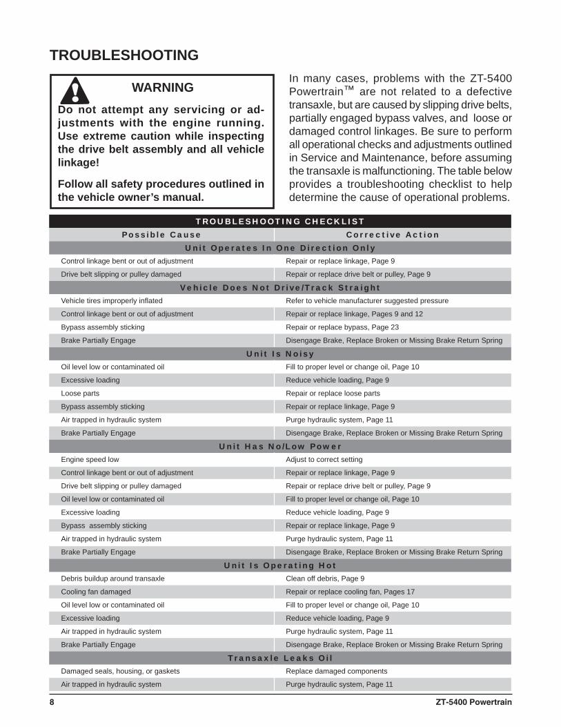
TROUBLESHOOTING CHECKLISTPossible Cause Corrective Action
Unit Operates In One Direction OnlyControl linkage bent or out of adjustment Repair or replace linkage, Page 9
Drive belt slipping or pulley damaged Repair or replace drive belt or pulley, Page 9
Vehicle Does Not Drive/Track StraightVehicle tires improperly infl ated Refer to vehicle manufacturer suggested pressure
Control linkage bent or out of adjustment Repair or replace linkage, Pages 9 and 12
Bypass assembly sticking Repair or replace bypass, Page 23
Brake Partially Engage Disengage Brake, Replace Broken or Missing Brake Return Spring
Unit Is NoisyOil level low or contaminated oil Fill to proper level or change oil, Page 10
Excessive loading Reduce vehicle loading, Page 9
Loose parts Repair or replace loose parts
Bypass assembly sticking Repair or replace linkage, Page 9
Air trapped in hydraulic system Purge hydraulic system, Page 11
Brake Partially Engage Disengage Brake, Replace Broken or Missing Brake Return Spring
Unit Has No/Low PowerEngine speed low Adjust to correct setting
Control linkage bent or out of adjustment Repair or replace linkage, Page 9
Drive belt slipping or pulley damaged Repair or replace drive belt or pulley, Page 9
Oil level low or contaminated oil Fill to proper level or change oil, Page 10
Excessive loading Reduce vehicle loading, Page 9
Bypass assembly sticking Repair or replace linkage, Page 9
Air trapped in hydraulic system Purge hydraulic system, Page 11
Brake Partially Engage Disengage Brake, Replace Broken or Missing Brake Return Spring
Unit Is Operating HotDebris buildup around transaxle Clean off debris, Page 9
Cooling fan damaged Repair or replace cooling fan, Pages 17
Oil level low or contaminated oil Fill to proper level or change oil, Page 10
Excessive loading Reduce vehicle loading, Page 9
Air trapped in hydraulic system Purge hydraulic system, Page 11
Brake Partially Engage Disengage Brake, Replace Broken or Missing Brake Return Spring
Transaxle Leaks OilDamaged seals, housing, or gaskets Replace damaged components
Air trapped in hydraulic system Purge hydraulic system, Page 11
TROUBLESHOOTINGIn many cases, problems with the ZT-5400 Powertrain™ are not related to a defective transaxle, but are caused by slipping drive belts, partially engaged bypass valves, and loose or damaged control linkages. Be sure to perform all operational checks and adjustments outlined in Service and Maintenance, before assuming the transaxle is malfunctioning. The table below provides a troubleshooting checklist to help determine the cause of operational problems.
WARNINGDo not attempt any servicing or ad-justments with the engine running.Use extreme caution while inspecting the drive belt assembly and all vehicle linkage!
Follow all safety procedures outlined in the vehicle owner’s manual.
ZT-5400 Powertrain 9
NOTE: Any servicing dealer attempting a warranty repair must have prior approval before conducting main-tenance of a Hydro-Gear® product unless the servicing dealer is a cur-rent Authorized Hydro-Gear Service Center.
EXTERNAL MAINTENANCERegular external maintenance of the ZT-5400 Powertrain™ should include the following:
1. Check the vehicle operator’s manual forthe recommended load ratings. Insure the current application does not exceedload rating.
2. Check oil level in accordance with Figure 3Page 10.
3. Inspect the vehicle drive belt, idler pulley(s),and idler spring(s). Insure that no beltslippage can occur. Slippage can cause lowinput speed to the transmission.
4. Inspect the transmission cooling fan forbroken or distorted blades and remove anyobstructions (grass clippings, leaves, dirt, etc.).
5. Inspect the parking brake and vehiclelinkage to insure proper actuation and adjustment of the parking brake.
6. Inspect the vehicle control linkage to the directional control arm on transaxle. Also,insure the control arm is securely fastenedto the trunnion arm of the transaxle.
7. Inspect the bypass mechanism on the transaxle and vehicle linkage to insure it actuates and releases fully.
SERVICE AND MAINTENANCEPROCEDURESAll the service and maintenance procedures presented on the following pages can be performed while the ZT-5400 Powertrain is mounted on the vehicle. Any repair procedures as mentioned in the tear down and assembly section of this manual must be performed after the unit has been removed from the vehicle.
FLUIDSThe fl uids used in Hydro-Gear products havebeen carefully selected, and only equivalent, or better products should be substituted.
Typically, an engine oil with a minimum ratingof 9.0 cSt (55 SUS) at 230°F (110° C) and an APIclassifi cation of SL is recommended. A 20W-50engine oil has been selected for use by the factoryand is recommended for normal operatingtemperatures. Biodegradable oils are not ap-proved for this unit as they degrade to quickly while in service.
FLUID VOLUME AND LEVELFluid volume information is provided in the Table below.
Certain situations may require additional fl uid to be added or even replaced. Refer to Page 10, Figure 3 and page 5 for the proper fi ll port location.
Fill the ZT-5400 Powertrain to the top of the oil fi ll port.
Recheck the fl uid level once the unit has beenoperated for approximately 1 minute.
Purging may be required. Refer to the purgingprocedures on page 11.
SERVICE AND MAINTENANCE
10 ZT-5400 Powertrain
(2.375)
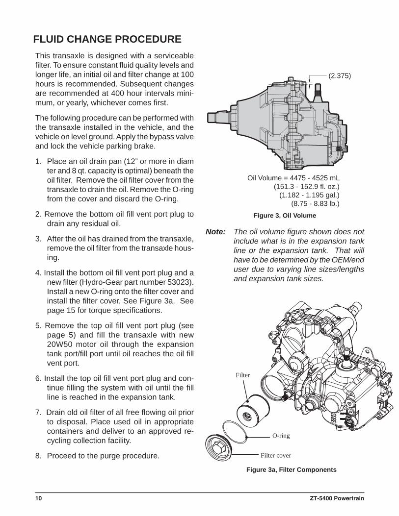
Oil Volume = 4475 - 4525 mL(151.3 - 152.9 fl. oz.)
(1.182 - 1.195 gal.)(8.75 - 8.83 lb.)
This transaxle is designed with a serviceable fi lter. To ensure constant fl uid quality levels and longer life, an initial oil and fi lter change at 100 hours is recommended. Subsequent changes are recommended at 400 hour intervals mini-mum, or yearly, whichever comes fi rst.
The following procedure can be performed with the transaxle installed in the vehicle, and the vehicle on level ground. Apply the bypass valve and lock the vehicle parking brake.
1. Place an oil drain pan (12” or more in diam ter and 8 qt. capacity is optimal) beneath the oil fi lter. Remove the oil fi lter cover from the transaxle to drain the oil. Remove the O-ring from the cover and discard the O-ring.
2. Remove the bottom oil fi ll vent port plug to drain any residual oil.
3. After the oil has drained from the transaxle, remove the oil fi lter from the transaxle hous-ing.
4. Install the bottom oil fi ll vent port plug and a new fi lter (Hydro-Gear part number 53023). Install a new O-ring onto the fi lter cover and install the fi lter cover. See Figure 3a. See page 15 for torque specifi cations.
5. Remove the top oil fi ll vent port plug (see page 5) and fill the transaxle with new 20W50 motor oil through the expansion tank port/fi ll port until oil reaches the oil fi ll vent port.
6. Install the top oil fi ll vent port plug and con-tinue fi lling the system with oil until the fi ll line is reached in the expansion tank.
7. Drain old oil fi lter of all free fl owing oil prior to disposal. Place used oil in appropriate containers and deliver to an approved re-cycling collection facility.
8. Proceed to the purge procedure.
FLUID CHANGE PROCEDURE
Note: The oil volume fi gure shown does not include what is in the expansion tank line or the expansion tank. That will have to be determined by the OEM/end user due to varying line sizes/lengths and expansion tank sizes.
Figure 3, Oil Volume
Filter
Filter cover
O-ring
Figure 3a, Filter Components
ZT-5400 Powertrain 11
PURGING PROCEDURESDue to the effects air has on efficiency in hydrostatic drive applications, it is critical that it be purged from the system.
These purge procedures should be imple-mented any time a hydrostatic system has been opened to facilitate maintenance or any additional oil has been added to the system.
Air creates ineffi ciency because its compres-sion and expansion rate is higher than that of the oil approved for use in hydrostatic drive systems.
The resulting symptoms in hydrostatic systems may be:
1. Noisy operation.
2. Lack of power or drive after short term operation.
3. High operation temperature and excessiveexpansion of oil.
Before starting, make sure the transaxle/trans-mission is at the proper oil level. If it is not, fi ll to the specifi cations outlined on page 9.
The following procedures should be performed with the vehicle drive wheels off the ground, then repeated under normal operating condi-tions.
1. With the bypass valve open and the enginerunning, slowly move the directional controlin both forward and reverse directions (5 to 6 times), as air is purged from the unit,the oil level will drop.
2. With the bypass valve closed and the engine running, slowly move the directionalcontrol in both forward and reverse directions (5 to 6 times). Check the oil level,and add oil as required after stopping engine.
3. It may be necessary to repeat Steps 1 and 2until all the air is completely purged from thesystem. When the transaxle moves forwardand reverse at normal speed purging iscomplete.
12 ZT-5400 Powertrain
WARNING
POTENTIAL FOR SERIOUS INJURY
Certain procedures require the vehicle engine to be operated and the vehicle to be raised off the ground. To prevent possible injury to the ser-vicing technician and/or bystanders, insure the vehicle is properly secured.
61
54
RETURN TO NEUTRAL SETTING
The return to neutral mechanism on the transax-le is designed to set the directional control into a neutral position when the operator removes their hand from the control lever. Follow the procedures below to properly adjust the return to neutral mechanism on the transaxle:
1. Confi rm the transaxle is in the operating mode(bypass disengaged). Raise the vehicle’s drivetires off the ground to allow free rotation.
NOTE: It may be necessary to remove the drive tire from the axle hub to access the linkage control and the transaxle return arm.
2. Remove the Original Equipment Manufac-turer’s (OEM’s) control linkage at the controlarm.
3. Start the engine and increase the throttle to full engine speed.
4. Check for axle rotation. If the axles do notrotate, go to Step 5. If the axles rotate, go to Step 6.
5. Stop the vehicle’s engine. Reattach and adjust the OEM linkage according to the OEM manual. Recheck according to Step 3 and 4. Start the vehicle engine.
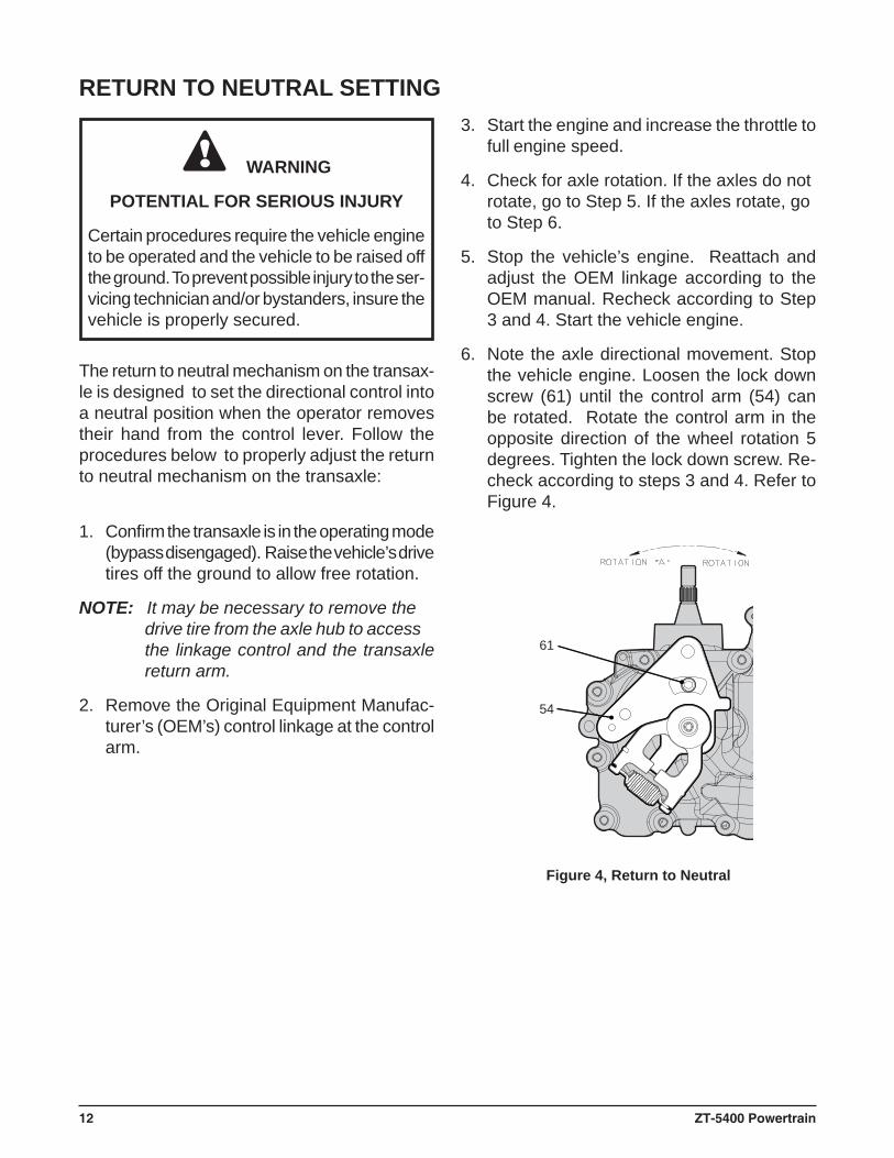
6. Note the axle directional movement. Stop the vehicle engine. Loosen the lock down screw (61) until the control arm (54) can be rotated. Rotate the control arm in the opposite direction of the wheel rotation 5 degrees. Tighten the lock down screw. Re-check according to steps 3 and 4. Refer to Figure 4.
Figure 4, Return to Neutral
ZT-5400 Powertrain 13
WARNING
POTENTIAL FOR SERIOUS INJURY
Certain procedures require the vehicle engine to be operated and the vehicle to be raised off the ground. To prevent possible injury to the ser-vicing technician and/or bystanders, insure the vehicle is properly secured.
54
168
165
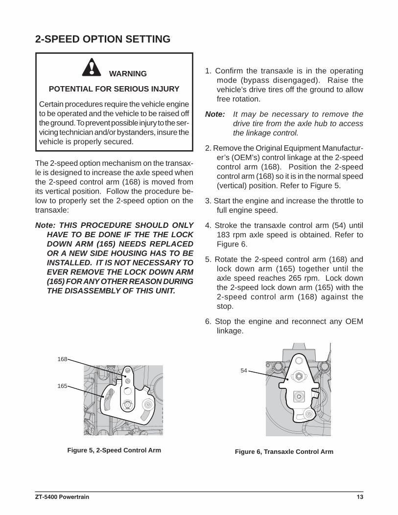
2-SPEED OPTION SETTING
Figure 5, 2-Speed Control Arm Figure 6, Transaxle Control Arm
The 2-speed option mechanism on the transax-le is designed to increase the axle speed when the 2-speed control arm (168) is moved from its vertical position. Follow the procedure be-low to properly set the 2-speed option on the transaxle:
Note: THIS PROCEDURE SHOULD ONLY HAVE TO BE DONE IF THE THE LOCK DOWN ARM (165) NEEDS REPLACED OR A NEW SIDE HOUSING HAS TO BE INSTALLED. IT IS NOT NECESSARY TO EVER REMOVE THE LOCK DOWN ARM (165) FOR ANY OTHER REASON DURING THE DISASSEMBLY OF THIS UNIT.
1. Confi rm the transaxle is in the operating mode (bypass disengaged). Raise the vehicle’s drive tires off the ground to allow free rotation.
Note: It may be necessary to remove the drive tire from the axle hub to access the linkage control.
2. Remove the Original Equipment Manufactur-er’s (OEM’s) control linkage at the 2-speed control arm (168). Position the 2-speed control arm (168) so it is in the normal speed (vertical) position. Refer to Figure 5.
3. Start the engine and increase the throttle to full engine speed.
4. Stroke the transaxle control arm (54) until 183 rpm axle speed is obtained. Refer to Figure 6.
5. Rotate the 2-speed control arm (168) and lock down arm (165) together until the axle speed reaches 265 rpm. Lock down the 2-speed lock down arm (165) with the 2-speed control arm (168) against the stop.
6. Stop the engine and reconnect any OEM linkage.
14 ZT-5400 Powertrain
TEAR DOWN AND REASSEMBLYHOW TO USE THIS MANUALEach subassembly illustrated in this section is illustrated by an exploded view showing the parts involved. The item reference num-bers in each illustration are for assembly instructions only. See page 37 for part names and descriptions. A complete exploded view and item list of the transaxle is provided on pages 36 and 37.
Many of the parts and subassemblies of this transaxle can be removed and serviced inde-pendently of other components. Where some components and assemblies must be removed before a given assembly can be serviced, that information is given at the beginning of the disassembly instructions.
GENERAL INSTRUCTIONSCleanliness is a primary means of assuring satisfactory life on repaired units. Thoroughly clean all exposed surfaces prior to any type of maintenance. Cleaning of all parts by us-ing a solvent wash and air drying is usually adequate. As with any precision equipment, all parts must be kept free of foreign material and chemicals.
Protect all exposed sealing surfaces and open cavities from damage and foreign material. The external surfaces should be cleaned before beginning any repairs.
Upon removal, it is recommended that all seals, O-rings, and gaskets be replaced. During installation lightly lubricate all seals, O-rings, gaskets with a clean petroleum jelly prior to assembly. Also protect the inner diameter of seals by covering the shaft with a cellophane (plastic wrap, etc.) material. Be sure all rem-nants of this covering are removed after ser-vicing.
Parts requiring replacement must be replaced from the appropriate kits identifi ed in the Items Listing, found on page 37. Use only original
Hydro-Gear® replacement parts found listed in BLN-51427 (CD) or in the authorized dealer section of the Hydro-Gear web site.
IMPORTANT: When internal repair is performed on the ZT-5400 Powertrain™, the fi lter assem-bly must be replaced.
TRANSAXLE REMOVALIt is necessary to remove the ZT-5400 Powertrain from the vehicle before performing the repair procedures presented in this section.
LIMITED DISASSEMBLYThe following procedures are presented in the order in which they must be performed to completely disassemble the unit. Do not disassemble the unit any farther than is necessary to accomplish the required repairs. Each disassembly procedure is followed by a corresponding assembly procedure.
Reassembly is accomplished by performing the “Assembly” portions of the procedures. If the unit has been completely disassembled, a summary of the assembly procedures, in the order in which they should occur, is given on page 33.
ZT-5400 Powertrain 15
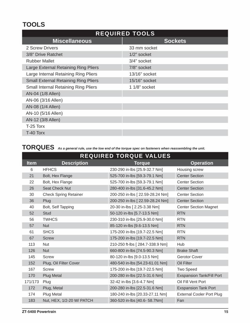
REQUIRED TOOLSMiscellaneous Sockets
2 Screw Drivers 33 mm socket 3/8” Drive Ratchet 1/2” socket Rubber Mallet 3/4” socket Large External Retaining Ring Pliers 7/8” socket Large Internal Retaining Ring Pliers 13/16” socket Small External Retaining Ring Pliers 15/16” socket Small Internal Retaining Ring Pliers 1 1/8” socket AN-04 (1/8 Allen) AN-06 (3/16 Allen) AN-08 (1/4 Allen) AN-10 (5/16 Allen) AN-12 (3/8 Allen) T-25 Torx T-40 Torx
REQUIRED TORQUE VALUESItem Description Torque Operation
6 HFHCS 230-290 in-lbs [25.9-32.7 Nm] Housing screw21 Bolt, Hex Flange 525-700 in-lbs [59.3-79.1 Nm] Center Section22 Bolt, Hex Flange 525-700 in-lbs [59.3-79.1 Nm] Center Section26 Seat Check Nut 280-400 in-lbs [31.6-45.2 Nm] Center Section30 Check Spring Retainer 200-250 in-lbs [ 22.59-28.24 Nm] Center Section36 Plug 200-250 in-lbs [ 22.59-28.24 Nm] Center Section40 Bolt, Self Tapping 20-30 in-lbs [ 2.25-3.38 Nm] Center Section Magnet52 Stud 50-120 in-lbs [5.7-13.5 Nm] RTN56 TWHCS 230-310 in-lbs [25.9-30.0 Nm] RTN57 Nut 85-120 in-lbs [9.6-13.5 Nm] RTN61 SHCS 175-200 in-lbs [19.7-22.5 Nm] RTN67 Screw 175-200 in-lbs [19.7-22.5 Nm] RTN113 Nut 210-250 ft-lbs [ 284.7-338.9 Nm] Hub126 Nut 660-800 in-lbs [74.5-90.3 Nm] Brake Shaft145 Screw 80-120 in-lbs [9.0-13.5 Nm] Gerotor Cover152 Plug, Oil Filter Cover 480-540 in-lbs [54.23-61.01 Nm] Oil Filter167 Screw 175-200 in-lbs [19.7-22.5 Nm] Two Speed170 Plug Metal 200-280 in-lbs [22.5-31.6 Nm] Exspansion Tank/Fill Port
171/173 Plug 32-42 in-lbs [3.6-4.7 Nm] Oil Fill Vent Port172 Plug, Metal 200-280 in-lbs [22.5-31.6 Nm] Exspansion Tank Port174 Plug Metal 180-240 in-lbs [20.33-27.11 Nm] External Cooler Port Plug183 Nut, HEX, 1/2-20 W/ PATCH 360-520 in-lbs [40.6- 58.7Nm] Fan
TOOLS
As a general rule, use the low end of the torque spec on fasteners when reassembling the unit.TORQUES
16 ZT-5400 Powertrain
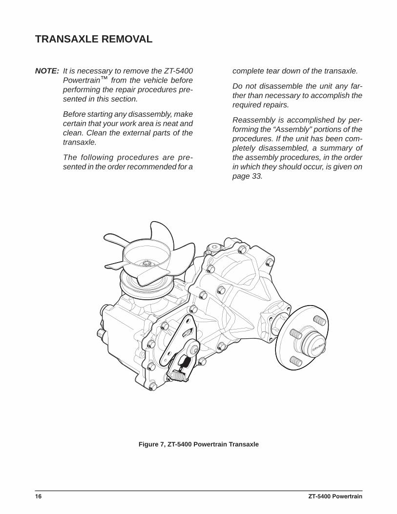
NOTE: It is necessary to remove the ZT-5400 Powertrain™ from the vehicle before performing the repair procedures pre-sented in this section.
Before starting any disassembly, make certain that your work area is neat and clean. Clean the external parts of the transaxle.
The following procedures are pre-sented in the order recommended for a
Figure 7, ZT-5400 Powertrain Transaxle
TRANSAXLE REMOVAL
complete tear down of the transaxle.
Do not disassemble the unit any far-ther than necessary to accomplish the required repairs.
Reassembly is accomplished by per-forming the “Assembly” portions of the procedures. If the unit has been com-pletely disassembled, a summary of the assembly procedures, in the order in which they should occur, is given on page 33.
ZT-5400 Powertrain 17
183
182
180
181
184
110
111115
113
114
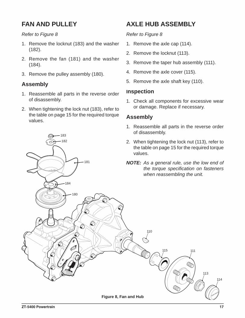
Refer to Figure 8
1. Remove the locknut (183) and the washer (182).
2. Remove the fan (181) and the washer (184).
3. Remove the pulley assembly (180).
Assembly1. Reassemble all parts in the reverse order
of disassembly.
2. When tightening the lock nut (183), refer to the table on page 15 for the required torque values.
Figure 8, Fan and Hub
FAN AND PULLEYRefer to Figure 8
1. Remove the axle cap (114).
2. Remove the locknut (113).
3. Remove the taper hub assembly (111).
4. Remove the axle cover (115).
5. Remove the axle shaft key (110).
Inspection1. Check all components for excessive wear
or damage. Replace if necessary.
Assembly1. Reassemble all parts in the reverse order
of disassembly.
2. When tightening the lock nut (113), refer to the table on page 15 for the required torque values.
NOTE: As a general rule, use the low end of the torque specifi cation on fasteners when reassembling the unit.
AXLE HUB ASSEMBLY
18 ZT-5400 Powertrain
65 6667
64
56
63
62
54
61
60
5958
51
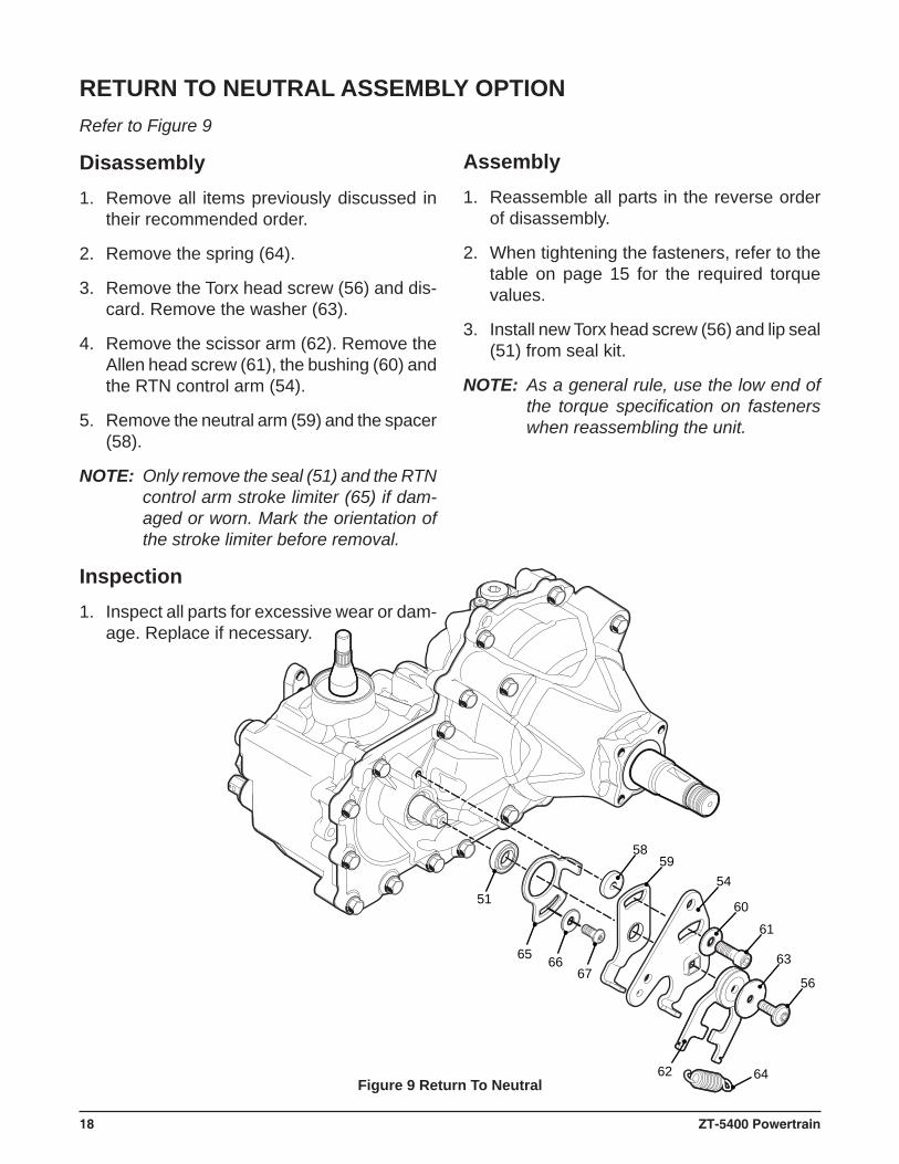
Figure 9 Return To Neutral
RETURN TO NEUTRAL ASSEMBLY OPTIONRefer to Figure 9
Disassembly1. Remove all items previously discussed in
their recommended order.
2. Remove the spring (64).
3. Remove the Torx head screw (56) and dis-card. Remove the washer (63).
4. Remove the scissor arm (62). Remove the Allen head screw (61), the bushing (60) and the RTN control arm (54).
5. Remove the neutral arm (59) and the spacer (58).
NOTE: Only remove the seal (51) and the RTN control arm stroke limiter (65) if dam-aged or worn. Mark the orientation of the stroke limiter before removal.
Inspection1. Inspect all parts for excessive wear or dam-
age. Replace if necessary.
Assembly1. Reassemble all parts in the reverse order
of disassembly.
2. When tightening the fasteners, refer to the table on page 15 for the required torque values.
3. Install new Torx head screw (56) and lip seal (51) from seal kit.
NOTE: As a general rule, use the low end of the torque specifi cation on fasteners when reassembling the unit.
ZT-5400 Powertrain 19
51
65 6667
5253 54
5557
56
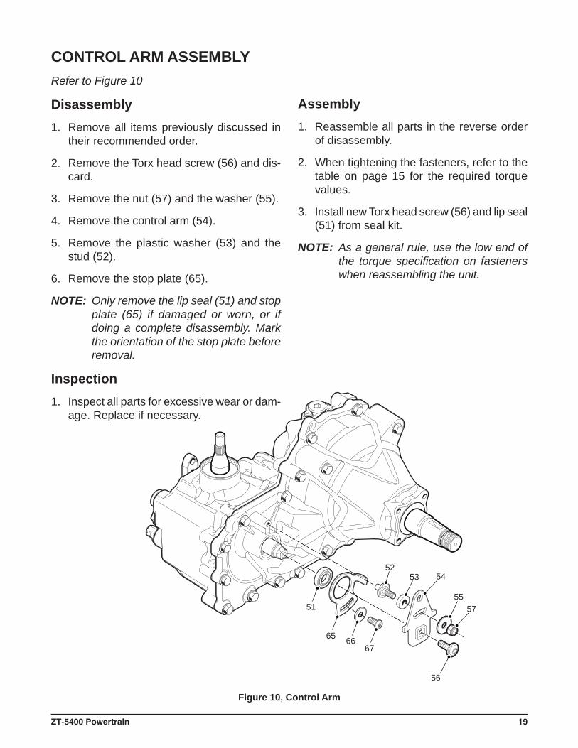
Figure 10, Control Arm
CONTROL ARM ASSEMBLYRefer to Figure 10
Disassembly1. Remove all items previously discussed in
their recommended order.
2. Remove the Torx head screw (56) and dis-card.
3. Remove the nut (57) and the washer (55).
4. Remove the control arm (54).
5. Remove the plastic washer (53) and the stud (52).
6. Remove the stop plate (65).
NOTE: Only remove the lip seal (51) and stop plate (65) if damaged or worn, or if doing a complete disassembly. Mark the orientation of the stop plate before removal.
Inspection1. Inspect all parts for excessive wear or dam-
age. Replace if necessary.
Assembly1. Reassemble all parts in the reverse order
of disassembly.
2. When tightening the fasteners, refer to the table on page 15 for the required torque values.
3. Install new Torx head screw (56) and lip seal (51) from seal kit.
NOTE: As a general rule, use the low end of the torque specifi cation on fasteners when reassembling the unit.
20 ZT-5400 Powertrain
152
151
150
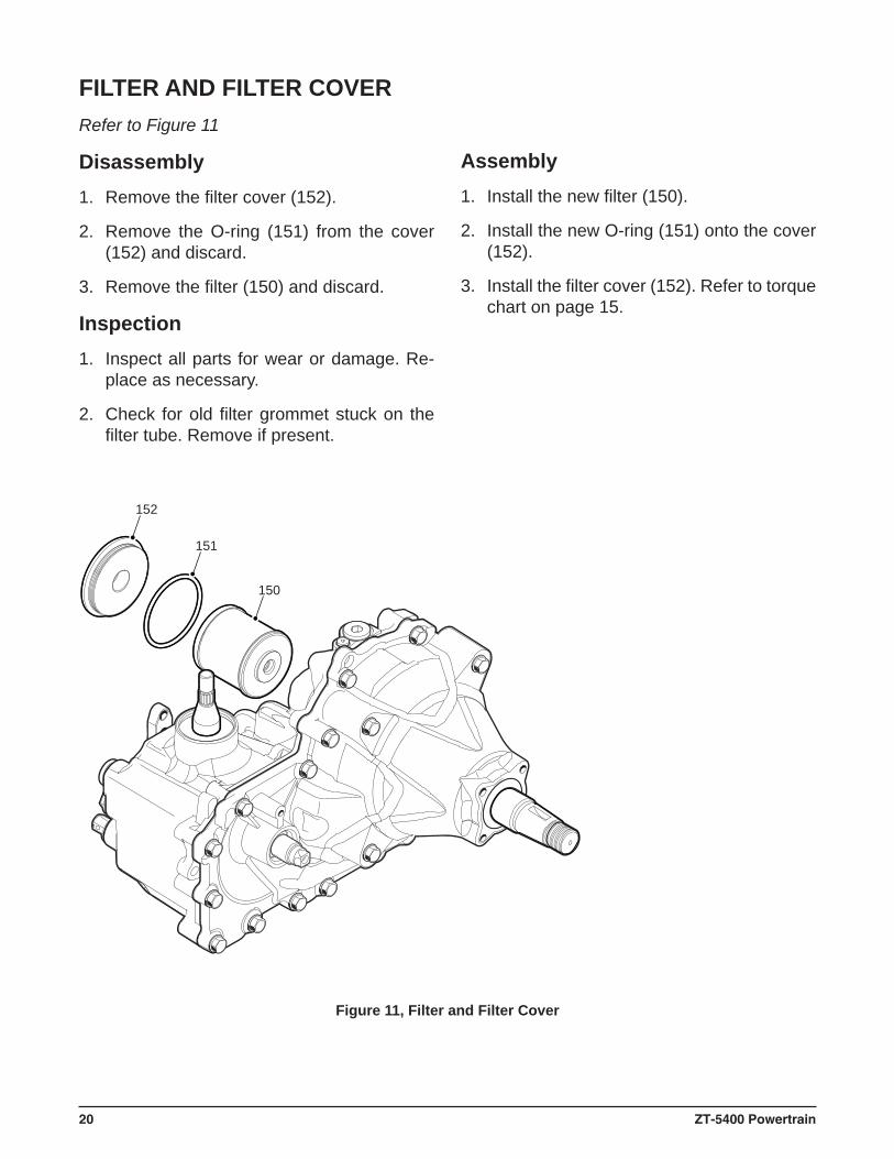
FILTER AND FILTER COVERRefer to Figure 11
Disassembly1. Remove the fi lter cover (152).
2. Remove the O-ring (151) from the cover (152) and discard.
3. Remove the fi lter (150) and discard.
Inspection1. Inspect all parts for wear or damage. Re-
place as necessary.
2. Check for old fi lter grommet stuck on the fi lter tube. Remove if present.
Assembly1. Install the new fi lter (150).
2. Install the new O-ring (151) onto the cover (152).
3. Install the fi lter cover (152). Refer to torque chart on page 15.
Figure 11, Filter and Filter Cover
ZT-5400 Powertrain 21
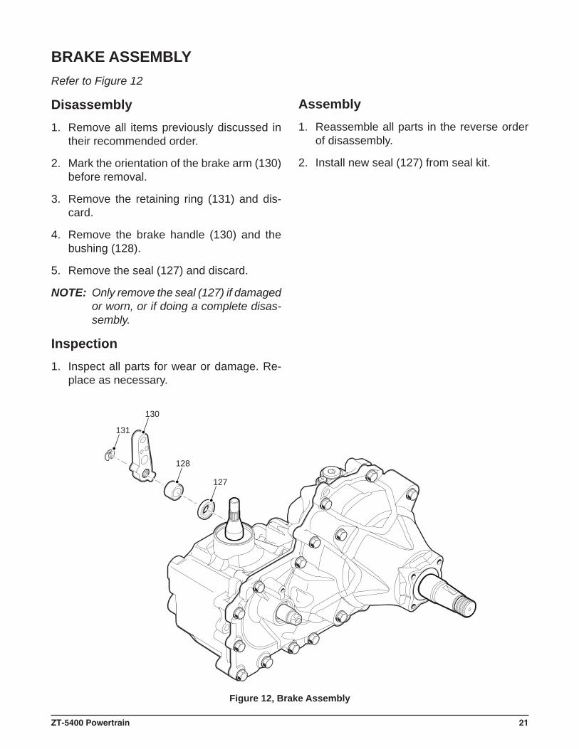
127
128
130
131
BRAKE ASSEMBLYRefer to Figure 12
Disassembly1. Remove all items previously discussed in
their recommended order.
2. Mark the orientation of the brake arm (130) before removal.
3. Remove the retaining ring (131) and dis-card.
4. Remove the brake handle (130) and the bushing (128).
5. Remove the seal (127) and discard.
NOTE: Only remove the seal (127) if damaged or worn, or if doing a complete disas-sembly.
Inspection1. Inspect all parts for wear or damage. Re-
place as necessary.
Assembly1. Reassemble all parts in the reverse order
of disassembly.
2. Install new seal (127) from seal kit.
Figure 12, Brake Assembly
22 ZT-5400 Powertrain
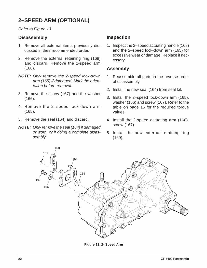
165
164
168
169
167
166
Refer to Figure 13
Disassembly1. Remove all external items previously dis-
cussed in their recommended order.
2. Remove the external retaining ring (169) and discard. Remove the 2-speed arm (168).
NOTE: Only remove the 2-speed lock-down arm (165) if damaged. Mark the orien-tation before removal.
3. Remove the screw (167) and the washer (166).
4. Remove the 2–speed lock-down arm (165).
5. Remove the seal (164) and discard.
NOTE: Only remove the seal (164) if damaged or worn, or if doing a complete disas-sembly.
2–SPEED ARM (OPTIONAL)
Figure 13, 2- Speed Arm
Inspection1. Inspect the 2–speed actuating handle (168)
and the 2–speed lock-down arm (165) for excessive wear or damage. Replace if nec-essary.
Assembly1. Reassemble all parts in the reverse order
of disassembly.
2. Install the new seal (164) from seal kit.
3. Install the 2–speed lock-down arm (165), washer (166) and screw (167). Refer to the table on page 15 for the required torque values.
4. Install the 2-speed actuating arm (168).screw (167).
5. Install the new external retaining ring (169).
ZT-5400 Powertrain 23
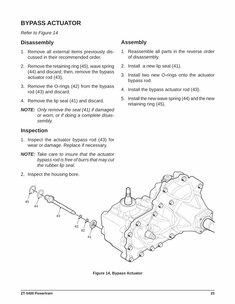
4445
43
4242
41
BYPASS ACTUATORRefer to Figure 14
Disassembly1. Remove all external items previously dis-
cussed in their recommended order.
2. Remove the retaining ring (45), wave spring (44) and discard; then, remove the bypass actuator rod (43).
3. Remove the O-rings (42) from the bypass rod (43) and discard.
4. Remove the lip seal (41) and discard.
NOTE: Only remove the seal (41) if damaged or worn, or if doing a complete disas-sembly.
Inspection1. Inspect the actuator bypass rod (43) for
wear or damage. Replace if necessary.
NOTE: Take care to insure that the actuator bypass rod is free of burrs that may cut the rubber lip seal.
2. Inspect the housing bore.
Assembly1. Reassemble all parts in the reverse order
of disassembly.
2. Install a new lip seal (41).
3. Install two new O-rings onto the actuator bypass rod.
4. Install the bypass actuator rod (43).
5. Install the new wave spring (44) and the new retaining ring (45).
Figure 14, Bypass Actuator
24 ZT-5400 Powertrain
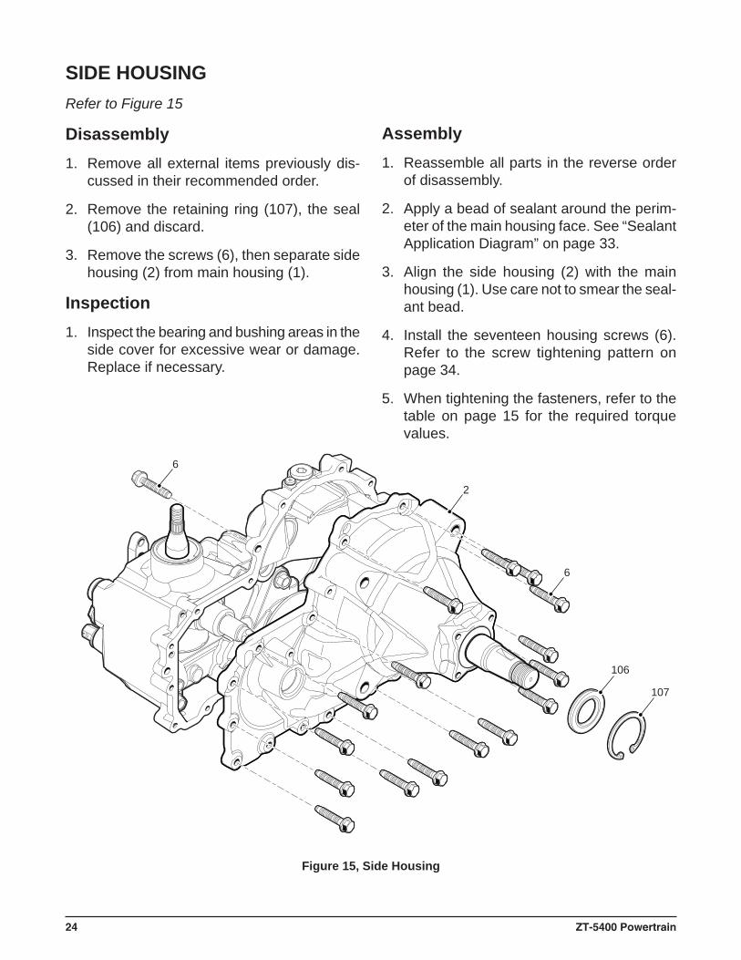
106
6
6
2
107
Figure 15, Side Housing
Refer to Figure 15
Disassembly1. Remove all external items previously dis-
cussed in their recommended order.
2. Remove the retaining ring (107), the seal (106) and discard.
3. Remove the screws (6), then separate side housing (2) from main housing (1).
Inspection1. Inspect the bearing and bushing areas in the
side cover for excessive wear or damage. Replace if necessary.
SIDE HOUSING
Assembly1. Reassemble all parts in the reverse order
of disassembly.
2. Apply a bead of sealant around the perim-eter of the main housing face. See “Sealant Application Diagram” on page 33.
3. Align the side housing (2) with the main housing (1). Use care not to smear the seal-ant bead.
4. Install the seventeen housing screws (6). Refer to the screw tightening pattern on page 34.
5. When tightening the fasteners, refer to the table on page 15 for the required torque values.
ZT-5400 Powertrain 25
PLANETARY ASSEMBLY
RING GEAR TAB
103
1
100
101 102 94
96
9798
103
104
105
95
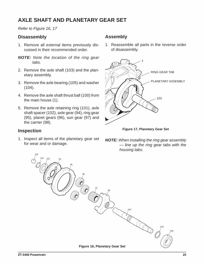
AXLE SHAFT AND PLANETARY GEAR SETRefer to Figure 16, 17
Disassembly1. Remove all external items previously dis-
cussed in their recommended order.
NOTE: Note the location of the ring gear tabs.
2. Remove the axle shaft (103) and the plan-etary assembly.
3. Remove the axle bearing (105) and washer (104).
4. Remove the axle shaft thrust ball (100) from the main house (1).
5. Remove the axle retaining ring (101), axle shaft spacer (102), axle gear (94), ring gear (95), planet gears (96), sun gear (97) and the carrier (98).
Inspection1. Inspect all items of the planetary gear set
for wear and or damage.
Assembly1. Reassemble all parts in the reverse order
of disassembly.
Figure 17, Planetary Gear Set
Figure 16, Planetary Gear Set
NOTE: When installing the ring gear assembly — line up the ring gear tabs with the housing tabs.
26 ZT-5400 Powertrain
144
145
143
142141
38
146
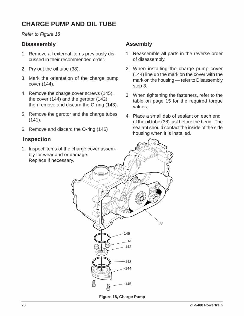
CHARGE PUMP AND OIL TUBE
Figure 18, Charge Pump
Refer to Figure 18
Disassembly1. Remove all external items previously dis-
cussed in their recommended order.
2. Pry out the oil tube (38).
3. Mark the orientation of the charge pump cover (144).
4. Remove the charge cover screws (145), the cover (144) and the gerotor (142), then remove and discard the O-ring (143).
5. Remove the gerotor and the charge tubes (141).
6. Remove and discard the O-ring (146)
Inspection1. Inspect items of the charge cover assem-
bly for wear and or damage.Replace if necessary.
Assembly1. Reassemble all parts in the reverse order
of disassembly.
2. When installing the charge pump cover (144) line up the mark on the cover with the mark on the housing — refer to Disassembly step 3.
3. When tightening the fasteners, refer to the table on page 15 for the required torque values.
4. Place a small dab of sealant on each end of the oil tube (38) just before the bend. The sealant should contact the inside of the side housing when it is installed.
ZT-5400 Powertrain 27
71
70
73
72
74
75
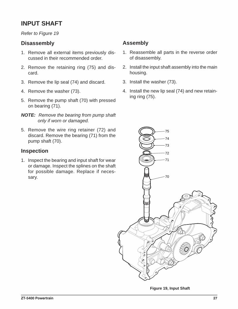
Figure 19, Input Shaft
INPUT SHAFTRefer to Figure 19
Disassembly1. Remove all external items previously dis-
cussed in their recommended order.
2. Remove the retaining ring (75) and dis-card.
3. Remove the lip seal (74) and discard.
4. Remove the washer (73).
5. Remove the pump shaft (70) with pressed on bearing (71).
NOTE: Remove the bearing from pump shaft only if worn or damaged.
5. Remove the wire ring retainer (72) and discard. Remove the bearing (71) from the pump shaft (70).
Inspection1. Inspect the bearing and input shaft for wear
or damage. Inspect the splines on the shaft for possible damage. Replace if neces-sary.
Assembly1. Reassemble all parts in the reverse order
of disassembly.
2. Install the input shaft assembly into the main housing.
3. Install the washer (73).
4. Install the new lip seal (74) and new retain-ing ring (75).
28 ZT-5400 Powertrain
PUMP BLOCK ASSEMBLY
50
85
88
87
82
86
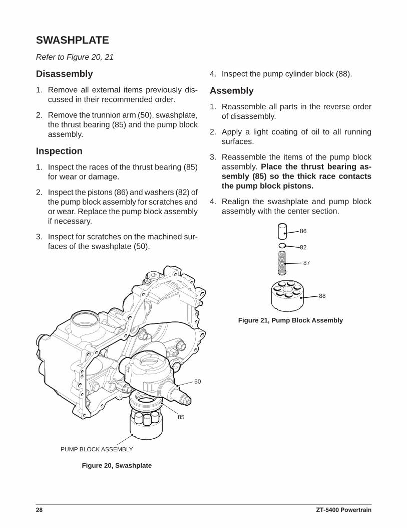
SWASHPLATE
Figure 20, Swashplate
Figure 21, Pump Block Assembly
Refer to Figure 20, 21
Disassembly1. Remove all external items previously dis-
cussed in their recommended order.
2. Remove the trunnion arm (50), swashplate, the thrust bearing (85) and the pump block assembly.
Inspection1. Inspect the races of the thrust bearing (85)
for wear or damage.
2. Inspect the pistons (86) and washers (82) of the pump block assembly for scratches and or wear. Replace the pump block assembly if necessary.
3. Inspect for scratches on the machined sur-faces of the swashplate (50).
4. Inspect the pump cylinder block (88).
Assembly1. Reassemble all parts in the reverse order
of disassembly.
2. Apply a light coating of oil to all running surfaces.
3. Reassemble the items of the pump block assembly. Place the thrust bearing as-sembly (85) so the thick race contacts the pump block pistons.
4. Realign the swashplate and pump block assembly with the center section.
ZT-5400 Powertrain 29
37
21
22
CENTER SECTION ASSEMBLY
MOTOR BLOCK ASSEMBLY
MOTOR SHAFT (90)
CENTER SECTION
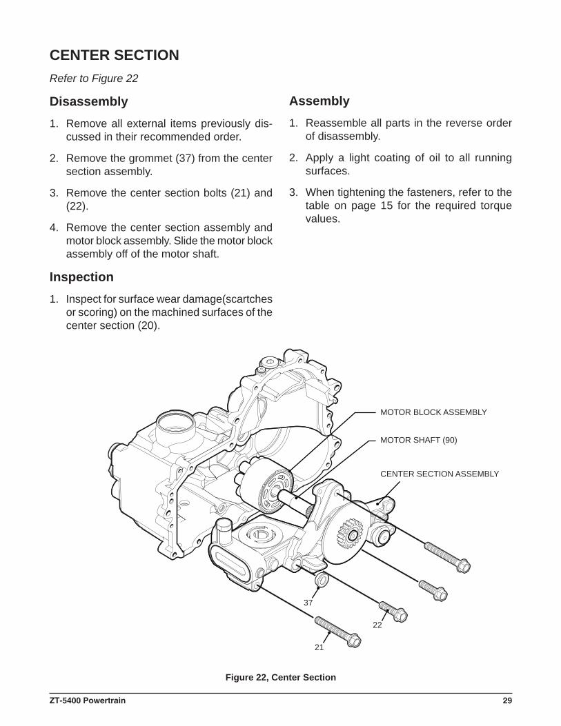
Figure 22, Center Section
Refer to Figure 22
Disassembly1. Remove all external items previously dis-
cussed in their recommended order.
2. Remove the grommet (37) from the center section assembly.
3. Remove the center section bolts (21) and (22).
4. Remove the center section assembly and motor block assembly. Slide the motor block assembly off of the motor shaft.
Inspection1. Inspect for surface wear damage(scartches
or scoring) on the machined surfaces of the center section (20).
Assembly1. Reassemble all parts in the reverse order
of disassembly.
2. Apply a light coating of oil to all running surfaces.
3. When tightening the fasteners, refer to the table on page 15 for the required torque values.
30 ZT-5400 Powertrain
126
90
125
91
9392
124
20
123
122
121
120
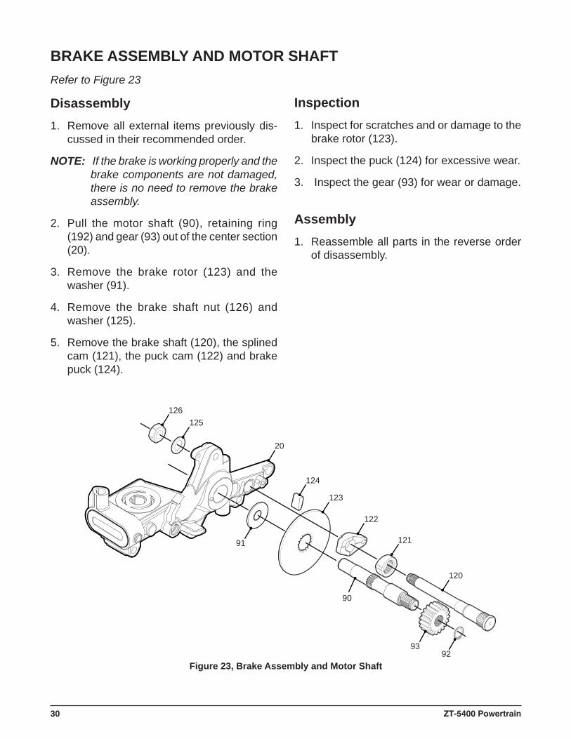
Figure 23, Brake Assembly and Motor Shaft
BRAKE ASSEMBLY AND MOTOR SHAFTRefer to Figure 23
Disassembly1. Remove all external items previously dis-
cussed in their recommended order.
NOTE: If the brake is working properly and the brake components are not damaged, there is no need to remove the brake assembly.
2. Pull the motor shaft (90), retaining ring (192) and gear (93) out of the center section (20).
3. Remove the brake rotor (123) and the washer (91).
4. Remove the brake shaft nut (126) and washer (125).
5. Remove the brake shaft (120), the splined cam (121), the puck cam (122) and brake puck (124).
Inspection1. Inspect for scratches and or damage to the
brake rotor (123).
2. Inspect the puck (124) for excessive wear.
3. Inspect the gear (93) for wear or damage.
Assembly1. Reassemble all parts in the reverse order
of disassembly.
ZT-5400 Powertrain 31
161162
160
80
8182
83 84
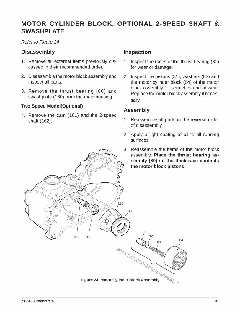
Figure 24, Motor Cylinder Block Assembly
MOTOR CYLINDER BLOCK, OPTIONAL 2-SPEED SHAFT & SWASHPLATERefer to Figure 24
Disassembly1. Remove all external items previously dis-
cussed in their recommended order.
2. Disassemble the motor block assembly and inspect all parts.
3. Remove the thrust bearing (80) and swashplate (160) from the main housing.
Two Speed Model(Optional)
4. Remove the cam (161) and the 2-speed shaft (162).
Inspection1. Inspect the races of the thrust bearing (80)
for wear or damage.
2. Inspect the pistons (81), washers (82) and the motor cylinder block (84) of the motor block assembly for scratches and or wear. Replace the motor block assembly if neces-sary.
Assembly1. Reassemble all parts in the reverse order
of disassembly.
2. Apply a light coating of oil to all running surfaces.
3. Reassemble the items of the motor block assembly. Place the thrust bearing as-sembly (80) so the thick race contacts the motor block pistons.
32 ZT-5400 Powertrain
36
3534
2526
2832
30
26
29
32
30
20
39
40
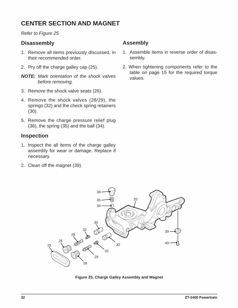
CENTER SECTION AND MAGNETRefer to Figure 25
Disassembly1. Remove all items previously discussed, in
their recommended order.
2. Pry off the charge galley cap (25).
NOTE: Mark orientation of the shock valves before removing.
3. Remove the shock valve seats (26).
4. Remove the shock valves (28/29), the springs (32) and the check spring retainers (30).
5. Remove the charge pressure relief plug (36), the spring (35) and the ball (34).
Inspection1. Inspect the all items of the charge galley
assembly for wear or damage. Replace if necessary.
2. Clean off the magnet (39).
Assembly1. Assemble items in reverse order of disas-
sembly.
2. When tightening components refer to the table on page 15 for the required torque values.
Figure 25, Charge Galley Assembly and Magnet
ZT-5400 Powertrain 33
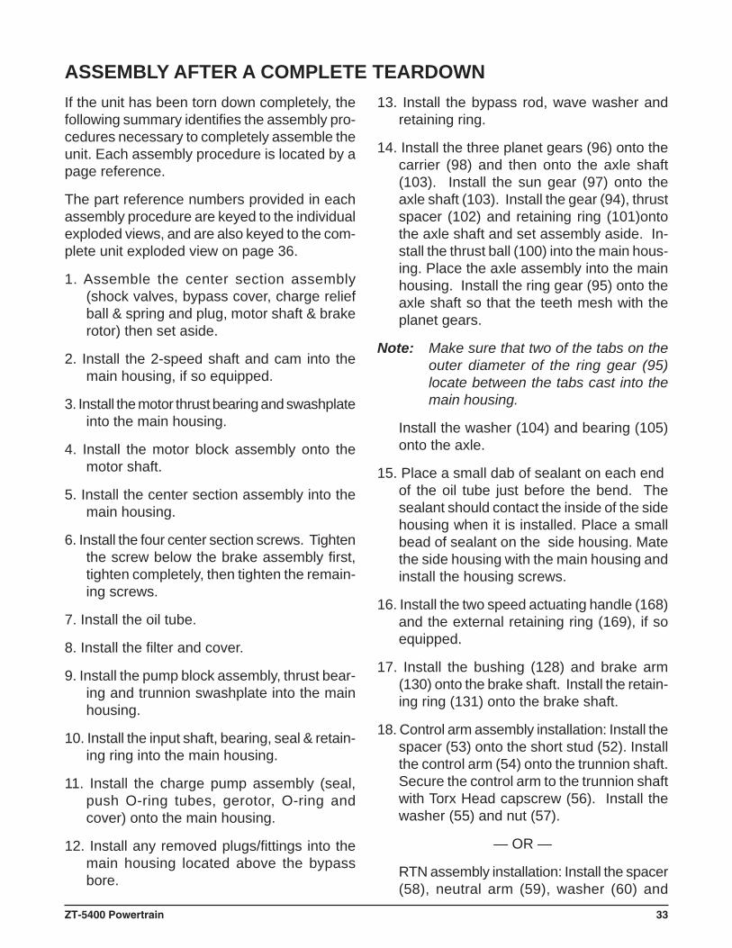
If the unit has been torn down completely, the following summary identifi es the assembly pro-cedures necessary to completely assemble the unit. Each assembly procedure is located by a page reference.
The part reference numbers provided in each assembly procedure are keyed to the individual exploded views, and are also keyed to the com-plete unit exploded view on page 36.
1. Assemble the center section assembly (shock valves, bypass cover, charge relief ball & spring and plug, motor shaft & brake rotor) then set aside.
2. Install the 2-speed shaft and cam into the main housing, if so equipped.
3. Install the motor thrust bearing and swashplate into the main housing.
4. Install the motor block assembly onto the motor shaft.
5. Install the center section assembly into the main housing.
6. Install the four center section screws. Tighten the screw below the brake assembly fi rst, tighten completely, then tighten the remain-ing screws.
7. Install the oil tube.
8. Install the fi lter and cover.
9. Install the pump block assembly, thrust bear-ing and trunnion swashplate into the main housing.
10. Install the input shaft, bearing, seal & retain-ing ring into the main housing.
11. Install the charge pump assembly (seal, push O-ring tubes, gerotor, O-ring and cover) onto the main housing.
12. Install any removed plugs/fi ttings into the main housing located above the bypass bore.
ASSEMBLY AFTER A COMPLETE TEARDOWN13. Install the bypass rod, wave washer and
retaining ring.
14. Install the three planet gears (96) onto the carrier (98) and then onto the axle shaft (103). Install the sun gear (97) onto the axle shaft (103). Install the gear (94), thrust spacer (102) and retaining ring (101)onto the axle shaft and set assembly aside. In-stall the thrust ball (100) into the main hous-ing. Place the axle assembly into the main housing. Install the ring gear (95) onto the axle shaft so that the teeth mesh with the planet gears.
Note: Make sure that two of the tabs on the outer diameter of the ring gear (95) locate between the tabs cast into the main housing.
Install the washer (104) and bearing (105) onto the axle.
15. Place a small dab of sealant on each end of the oil tube just before the bend. The sealant should contact the inside of the side housing when it is installed. Place a small bead of sealant on the side housing. Mate the side housing with the main housing and install the housing screws.
16. Install the two speed actuating handle (168) and the external retaining ring (169), if so equipped.
17. Install the bushing (128) and brake arm (130) onto the brake shaft. Install the retain-ing ring (131) onto the brake shaft.
18. Control arm assembly installation: Install the spacer (53) onto the short stud (52). Install the control arm (54) onto the trunnion shaft. Secure the control arm to the trunnion shaft with Torx Head capscrew (56). Install the washer (55) and nut (57).
— OR —
RTN assembly installation: Install the spacer (58), neutral arm (59), washer (60) and
34 ZT-5400 Powertrain
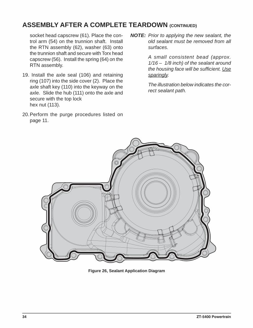
Figure 26, Sealant Application Diagram
ASSEMBLY AFTER A COMPLETE TEARDOWN (CONTINUED)
socket head capscrew (61). Place the con-trol arm (54) on the trunnion shaft. Install the RTN assembly (62), washer (63) onto the trunnion shaft and secure with Torx head capscrew (56). Install the spring (64) on the RTN assembly.
19. Install the axle seal (106) and retaining ring (107) into the side cover (2). Place the axle shaft key (110) into the keyway on the axle. Slide the hub (111) onto the axle and secure with the top lock hex nut (113).
20. Perform the purge procedures listed on page 11.
NOTE: Prior to applying the new sealant, the old sealant must be removed from all surfaces.
A small consistent bead (approx.1/16 – 1/8 inch) of the sealant around the housing face will be suffi cient. Use sparingly.
The illustration below indicates the cor-rect sealant path.
ZT-5400 Powertrain 35
From Opposite Direction
11
12
1014
16
17
15
13
6
7 1
48
3 2 5 9
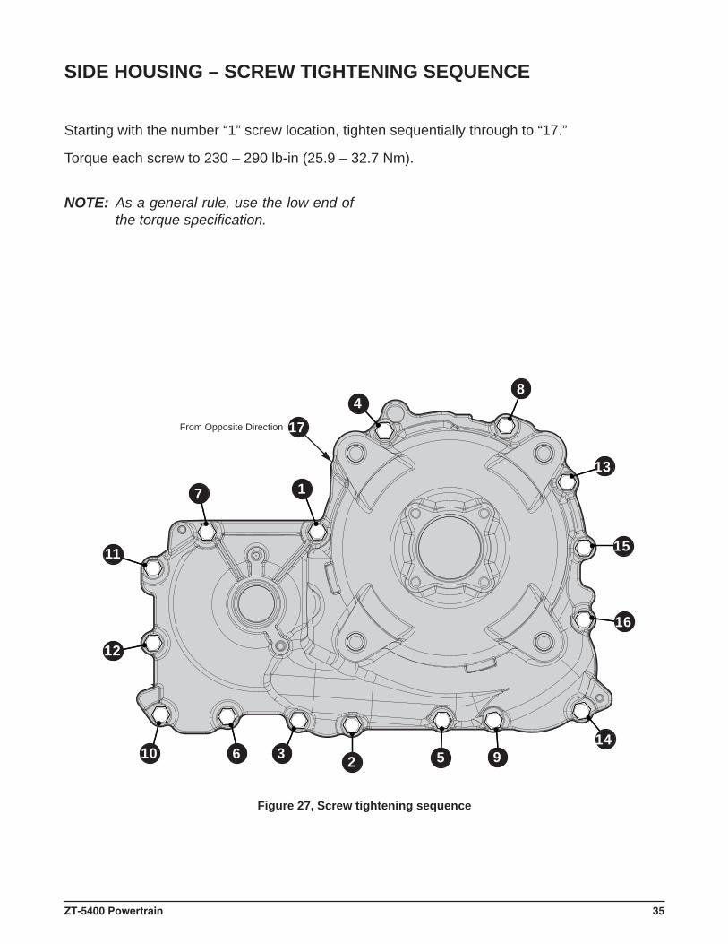
Figure 27, Screw tightening sequence
Starting with the number “1” screw location, tighten sequentially through to “17.”
Torque each screw to 230 – 290 lb-in (25.9 – 32.7 Nm).
NOTE: As a general rule, use the low end of the torque specifi cation.
SIDE HOUSING – SCREW TIGHTENING SEQUENCE
36 ZT-5400 Powertrain
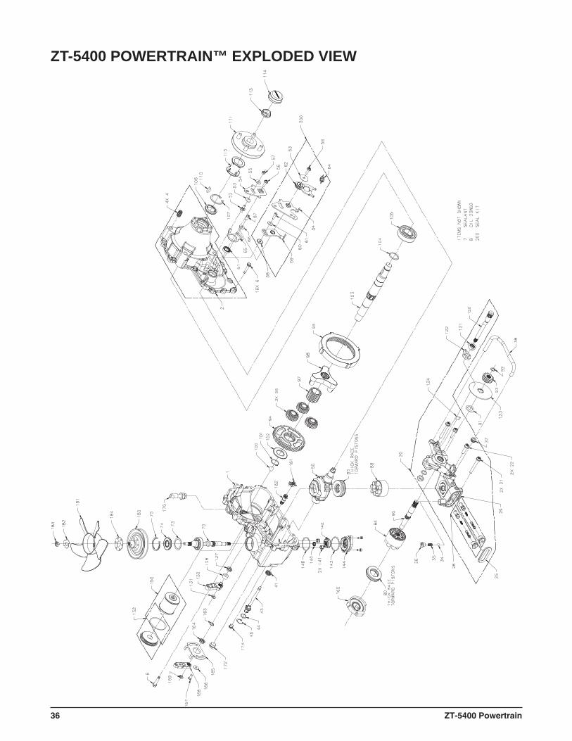
ZT-5400 POWERTRAIN™ EXPLODED VIEW
ZT-5400 Powertrain 37
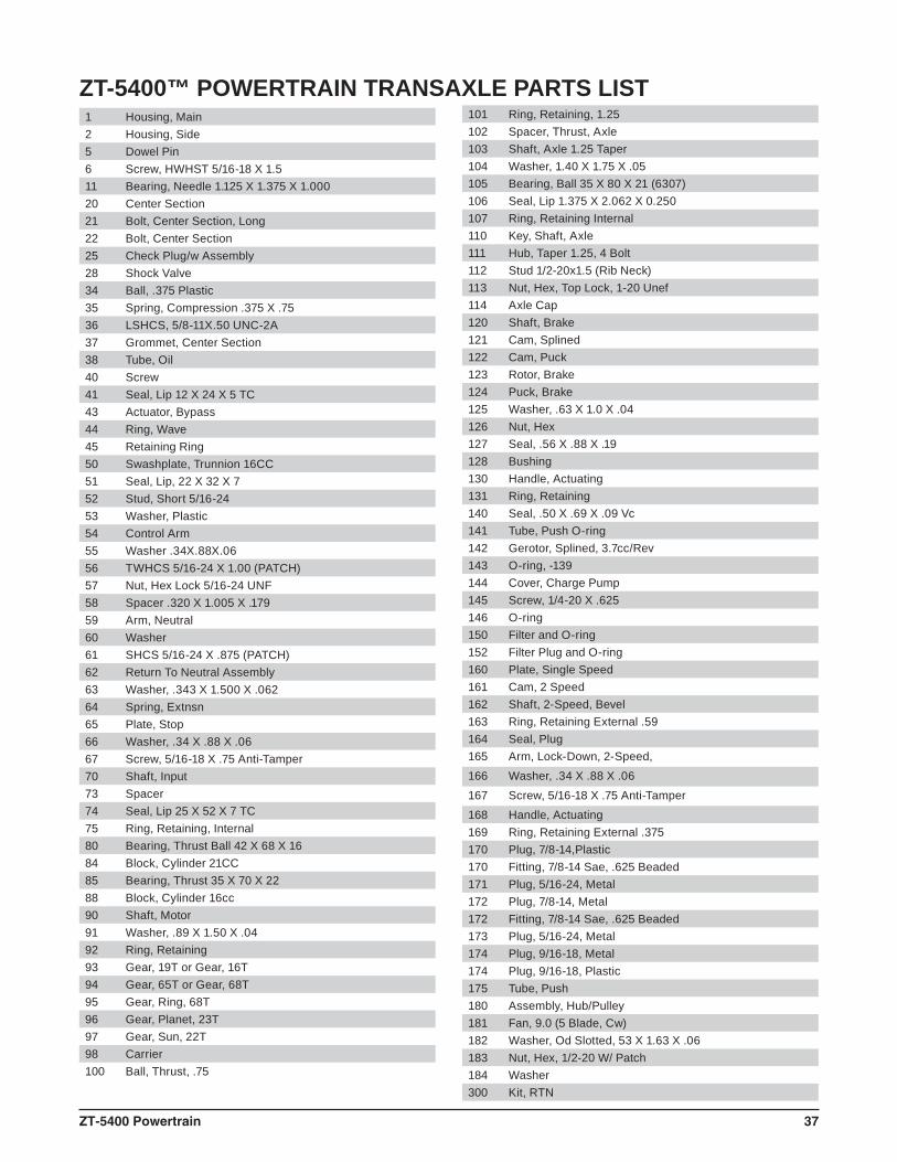
ZT-5400™ POWERTRAIN TRANSAXLE PARTS LIST 1 Housing, Main2 Housing, Side5 Dowel Pin6 Screw, HWHST 5/16-18 X 1.511 Bearing, Needle 1.125 X 1.375 X 1.00020 Center Section21 Bolt, Center Section, Long22 Bolt, Center Section25 Check Plug/w Assembly28 Shock Valve34 Ball, .375 Plastic35 Spring, Compression .375 X .7536 LSHCS, 5/8-11X.50 UNC-2A37 Grommet, Center Section38 Tube, Oil40 Screw41 Seal, Lip 12 X 24 X 5 TC43 Actuator, Bypass44 Ring, Wave45 Retaining Ring50 Swashplate, Trunnion 16CC51 Seal, Lip, 22 X 32 X 752 Stud, Short 5/16-2453 Washer, Plastic54 Control Arm55 Washer .34X.88X.0656 TWHCS 5/16-24 X 1.00 (PATCH)57 Nut, Hex Lock 5/16-24 UNF58 Spacer .320 X 1.005 X .17959 Arm, Neutral60 Washer61 SHCS 5/16-24 X .875 (PATCH)62 Return To Neutral Assembly63 Washer, .343 X 1.500 X .06264 Spring, Extnsn65 Plate, Stop66 Washer, .34 X .88 X .0667 Screw, 5/16-18 X .75 Anti-Tamper70 Shaft, Input73 Spacer74 Seal, Lip 25 X 52 X 7 TC75 Ring, Retaining, Internal80 Bearing, Thrust Ball 42 X 68 X 1684 Block, Cylinder 21CC85 Bearing, Thrust 35 X 70 X 2288 Block, Cylinder 16cc90 Shaft, Motor91 Washer, .89 X 1.50 X .0492 Ring, Retaining93 Gear, 19T or Gear, 16T94 Gear, 65T or Gear, 68T95 Gear, Ring, 68T96 Gear, Planet, 23T97 Gear, Sun, 22T98 Carrier100 Ball, Thrust, .75
101 Ring, Retaining, 1.25102 Spacer, Thrust, Axle103 Shaft, Axle 1.25 Taper104 Washer, 1.40 X 1.75 X .05105 Bearing, Ball 35 X 80 X 21 (6307)106 Seal, Lip 1.375 X 2.062 X 0.250107 Ring, Retaining Internal110 Key, Shaft, Axle111 Hub, Taper 1.25, 4 Bolt112 Stud 1/2-20x1.5 (Rib Neck)113 Nut, Hex, Top Lock, 1-20 Unef114 Axle Cap120 Shaft, Brake121 Cam, Splined122 Cam, Puck123 Rotor, Brake124 Puck, Brake125 Washer, .63 X 1.0 X .04126 Nut, Hex127 Seal, .56 X .88 X .19128 Bushing130 Handle, Actuating131 Ring, Retaining140 Seal, .50 X .69 X .09 Vc141 Tube, Push O-ring142 Gerotor, Splined, 3.7cc/Rev143 O-ring, -139144 Cover, Charge Pump145 Screw, 1/4-20 X .625146 O-ring150 Filter and O-ring152 Filter Plug and O-ring160 Plate, Single Speed161 Cam, 2 Speed162 Shaft, 2-Speed, Bevel163 Ring, Retaining External .59164 Seal, Plug165 Arm, Lock-Down, 2-Speed,166 Washer, .34 X .88 X .06167 Screw, 5/16-18 X .75 Anti-Tamper168 Handle, Actuating169 Ring, Retaining External .375170 Plug, 7/8-14,Plastic170 Fitting, 7/8-14 Sae, .625 Beaded171 Plug, 5/16-24, Metal172 Plug, 7/8-14, Metal172 Fitting, 7/8-14 Sae, .625 Beaded173 Plug, 5/16-24, Metal174 Plug, 9/16-18, Metal174 Plug, 9/16-18, Plastic175 Tube, Push180 Assembly, Hub/Pulley181 Fan, 9.0 (5 Blade, Cw)182 Washer, Od Slotted, 53 X 1.63 X .06183 Nut, Hex, 1/2-20 W/ Patch184 Washer300 Kit, RTN
38 ZT-5400 Powertrain
Axial Piston: Type of design for hydraulic motors and pumps in which the pistons are arranged parallel with the spindle (input or output shaft).
Bypass Valve: A valve whose primary function is to open a path for the fl uid to bypass the motor or pump. Also referred to occasionally as the freewheel valve or dump valve.
Case Drain Line (Return Line): A line returning fl uid from the component housing to the reser-voir.
Cavitation: A concentrated gaseous condition within the fl uid causing the rapid implosion of a gaseous bubble.
Center Section: A device which acts as the valve body and manifold of the transmission.
Charge Pump: A device which supplies replenishing fl uid to the fl uid power system (closed loop).
Charge Pressure: The pressure at which replenishing fl uid is forced into a fl uid power system.
Charge Relief Valve: A pressure control valve whose primary function is to limit pressure in the charge circuit.
Check Valve: A valve whose primary function is to restrict fl ow in one direction.
Closed Loop: A sealed and uninterrupted circulating path for fl uid fl ow from the pump to the motor and back.
Decay Rate: The ratio of pressure decay over time.
End Cap: See “Center Section.”
Entrained Air: A mechanically generated mixture of air bubbles having a tendency to separate from the liquid phase.
Gerotor: A formed rotor set operating about an eccentric that provides a fi xed displacement for pumps or motors.
Hydraulic Motor: A device which converts hydraulic fl uid power into mechanical force and mo-tion by transfer of fl ow under pressure.
Hydraulic Pump: A device which converts mechanical force and motion into hydraulic fl uid power by producing fl ow.
Hydrostatic Pump: See “Hydraulic Pump.”
Hydrostatic Transaxle: A multi component assembly including a gear case and a hydrostati-transmission.
Hydrostatic Transmission: The combination of a hydraulic pump and motor in one housing to form a device for the control and transfer of power.
Inlet Line: A supply line to the pump.
GLOSSARY OF TERMS
ZT-5400 Powertrain 39
Integrated Zero-Turn Transaxle: The combination of a hydrostatic transmission and gear case in one housing to form a complete transaxle.
Manifold: A conductor which provides multiple connection ports.
Neutral: Typically described as a condition in which fl uid fl ow and system pressure is below that which is required to turn the output shaft of the motor.
Pressure Decay: A falling pressure.
Priming: The fi lling of the charge circuit and closed loop of the fl uid power system during start up, frequently achieved by pressurizing the fl uid in the inlet line.
Purging: The act of replacing air with fl uid in a fl uid power system by forcing fl uid into all of the components and allowing the air a path of escape.
Rated Flow: The maximum fl ow that the power supply system is capable of maintaining at a specifi c operating pressure.
Scoring: Scratches in the direction of motion of mechanical parts caused by abrasive contami-nants.
Swash Plate: A mechanical device used to control the displacement of the pump pistons in a fl uid power system.
System Charge Check Valve: A valve controlling the replenishing fl ow of fl uid from a charge circuit to the closed loop in a fl uid power system.
System Pressure: The pressure which overcomes the total resistance in a system, including all effi ciency losses.
Valve: A device which controls fl uid fl ow direction, pressure, or fl ow rate.
Variable Displacement Pump: A pump in which the displacement per revolution can be var-ied.
Volumetric Displacement: The volume for one revolution.
40 ZT-5400 Powertrain
NOTES

ZT-5400 Powertrain 41
NOTES

© 2009 HYDRO-GEAR
Printed in U.S.A. Rev. P2