Embed Size (px)
Citation preview
Installation and ServicingCondensing Boilers/Flexicom hx12 hx G.C.No. 41-315-28
15 hx G.C.No. 41-315-29
18 hx G.C.No. 41-315-42
24 hx G.C.No. 41-315-61
30 hx G.C.No. 41-315-67
38 hx G.C.No. 41-315-68

Thank you for installing a new Glow-worm appliance in your home.Glow-worm appliances are manufactured to the very highest standard so we are pleased to offer
our customers a Comprehensive Guarantee.This product is guaranteed for 24 months from the date of installation or 30 months from the date
of manufacture, whichever is the shorter, for parts and labour. The second year of the parts guarantee, from the beginning of the 13th month onwards after
installation or manufacture, is conditional upon the boiler having been serviced by a competent person approved at the time by the Health and Safety Executive.
in accordance with the manufacturer’s recommendations. We strongly recommend regular servicing of your gas appliance, but where the condition is not met, any chargeable spare parts or components issued within the applicable guarantee period still benefit from a 12 month warranty
from the date of issue by the manufacturer.We recommend you complete and return as soon as possible your guarantee registration card.
If your guarantee registration card is missing you can obtain a copy or record your registration by telephoning the Glow-worm Customer Service number 01773 828100.
Guarantee Registration
Customer Service: 01773 828100
Technical Helpline: 01773 828300
General and Sales enquiries: Tel. 01773 824639 Fax: 01773 820569
To register your Glow-worm appliance call:0800 0732142
Benchmark places responsibilities on both manufacturers and installers. The purpose is to ensure that customers are provided with the correct equipment for their needs, that it is installed, commissioned and serviced in accordance with the manufacturer’s instructions by competent persons and that it meets the requirements of the appropriate Building Regulations. The Benchmark Checklist can be used to demonstrate compliance with Building Regulations and should be provided to the customer for future reference.Installers are required to carry out installation, commissioning and servicing work in accordance with the Benchmark Code of Practice which is available from the Heating and Hotwater Industry Council who manage and promote the Scheme.Visit www.centralheating.co.uk for more information.
Table of ConTenTS
- 3 -
These instructions consist of, Installation, Servicing, fault finding, Replacement of Parts and Spares. The instructions are an integral part of the appliance and must, to comply
with the current issue of the Gas Safety (Installation and Use) Regulations, be handed to the user on completion of the installation.
ConTenTS DeSCRIPTIon SeCTIon PaGe
Warnings 4Important Information 4 Statutory Requirements 5 Boiler Design 6Safety Devices 6Servicing, Maintenance and Spare Parts 6
Boiler Specification 1 7Boiler Dimensions and Hydraulic Schematic 2 8 Boiler Location, Clearances and Ventilation 3 9 Evacuation of Combustion Gas 4 10 Water Systems 5 14 Installation Preparation 6 18Boiler Fixing 7 19 Gas/Water and Appliance Connection 8 20Condensate Connections 9 21 Electrical Connection 10 23Commissioning 11 24
Servicing 12 27Fault Finding 13 32Replacement of Parts 14 38 Spare Parts 15 43Manual Handling 16 44Declaration of Conformity 17 45Commissioning Checklist 46Service Interval Record 47
InTRoDUCTIon
InSTallaTIon
MaInTenanCe

0020107230_00 - 06/11 - Glow-worm
INTRODUCTION
- 4 -
WaRnInGSGas leak or fault
Turn off the gas emergency control valve immediately. Eliminate all sources of ignition, i.e.smoking, blowlamps, hot air guns etc. Do not operate electrical lights or switches either on or off. Open all doors and windows,ventilate the
area.Sheet Metal Parts
This boiler contains metal parts (components) and care should be taken when handling and cleaning, with particular regard to edges.
Sealed ComponentsUnder no circumstances must the User interfere with or adjust sealed parts.
Gas CategoryThis boiler is for use only on G20 natural gas.
Gas Safety (Installation and Use) RegulationsIn your own interests and that of safety, it is the Law that ALL gas appliances are installed by a competent person approved at the time by the Health and Safety Executive in accordance with the current issue of these regulations.
Control of Substances Hazardous to HealthUnder Section 6 of The Health and Safety at Work Act 1974, we are required to provide information on substances hazardous to health. The adhesives and sealants used in this appliance are cured and give no known hazard in this state.
Manual HandlingWith regards to the “Manual Handling Operations, 1992 Regulations”, the appliance exceeds the recommended weight for a one man lift, refer to section 16 for more information.The handling of the boiler may involve lifting, pushing and pulling, the use of a sack truck may be required.The following handling techniques and precautions should be considered:- Grip the boiler at its base- Be physically capable- Use safety clothing where appropriate, e.g. gloves, safety footwear.Ensure safe lifting techniques are used- Keep back straight.- Avoid twisting at the waist.- Avoid upper body/top heavy bending.- Always grip using the palm of the hand.- Use designated hand holds.- Keep load as close to body as possible.- Always use assistance if required.
electrical SupplyThe boiler MUST be earthed.All system components shall be of an approved type and all wiring to current I.E.E. wiring regulations.External wiring must be correctly earthed, polarised and in accordance with the relevant standards.In Gb, this is BS 7671.In Ie, this is the current edition of ETCI rules.The boiler MUST be connected to a permanent 230V ac, 50Hz supply.Connection of the whole electrical system of the boiler, including any heating controls, to the electrical supply MUST be through one common isolator and must be fused 3 Amp maximum.Isolation should be by a double pole switched fused spur box, with a minimum gap of 3mm for both poles. The fused spur box should be readily accessible and preferably adjacent to the appliance. It should be identified as to its use.Alternatively connection can be made through an unswitched shuttered socket and 3A fused 3-pin plug both to the current issue of BS 1363, provided they are not used in a room containing a bath or shower.Wiring to the boiler must be PVC 85OC insulated cable, not less than 0.75mm2 (24/0.20mm).
Testing and CertificationThis boiler is tested and certificated for safety and performance. It is, therefore, important that no alteration is made to the boiler, without permission, in writing, by Glow-worm.Any alteration not approved by Glow-worm, could invalidate the certification, boiler warranty and may also infringe the current issue of the statutory requirements.
Important Information
0020107230_00 - 06/11 - Glow-worm
INTRODUCTION
- 5 -
Ce MarkThis boiler meets the requirements of Statutory Instrument, No. 3083 The Boiler (Efficiency) Regulations, and therefore is deemed to meet the requirements of Directive 92/42/EEC on the efficiency requirements for new hot water boilers fired with liquid or gaseous fuels.Type test for purposes of Regulation 5 certified by: Notified body 0087.Product/production certified by: Notified body 0086.The CE mark on this appliance shows compliance with:1. Directive 2009/142/EC on the approximation of the laws of the Member States relating to appliances burning gaseous fuels.2. Directive 73/23/EEC on the harmonisation of the Laws of the Member States relating to electrical equipment designed for use within certain voltage limits.3. Directive 89/336/EEC on the approximation of the Laws of the Member States relating to electromagnetic compatibility.
IMPoRTanTWhere no British Standards exists, materials and equipment should be fit for their purpose and of suitable quality and workmanship.The installation of this boiler must be carried out by a competent person approved at the time by the Health and Safety Executive in accordance the rules in force in the countries of destination.Manufacturer’s instructions must not be taken as overriding statutory requirements.
Statutory RequirementsIn Gb, the installation of the boiler must comply with the requirements of the current issue of BS6798 and be carried out by a competent person, approved at the time by the Health and Safety Executive, as described in the following regulations:The manufacturer’s instructions supplied.The Gas Safety (Installation and Use) Regulations. The appropriate Buildings Regulations either The Building Regulations, The Building Regulations (Scotland),The Building Regulations (Northern Ireland).The Water Supply (water fittings) Regulations 1999 and water byelaws 2000, Scotland.The Health and Safety at Work Act, Control of Substances Hazardous to Health (COSHH). The Current I.E.E. Wiring Regulations.Where no specific instructions are given, reference should be made to the relevant British Standard Code of Practice.In Ie, the installation must be carried out by a competent person approved at the time by the Health and Safety Executive and installed in accordance with the current edition of I.S.813 “Domestic Gas Installations”, the current Building Regulations and reference should be made to the current ETCI rules for Electrical Installation.Gb: the following Codes of Practice apply:BS4814, BS6798, BS5440 Part 1 and 2, BS5546 Part 1, BS5449, BS6891, BS6700, BS7074 Part 1 and 2, BS7593, BS7671.Ie: I.S.813, BS5546, BS 5449, BS 7074, BS 7593.noTe: For further information, see the current issue of the Building Regulations, approved document L1 ( in the UK) and the following current issues of:1) Central heating system specification (CheSS) and 2) Controls for domestic central heating system and hot water. BRECSU.
Gas SupplyThe gas installation must be in accordance with the relevant standards.In Gb, this is BS6891.In Ie, this is the current edition of I.S.813 “Domestic Gas Installations”.The supply from the governed meter must be of adequate size to provide a steady inlet working pressure of 20mbar (8in wg) at the boiler.On completion, test the gas installation for tightness using the pressure drop method and suitable leak detection fluid, purge in accordance with the above standard.
Domestic Hot WaterAll domestic hot water circuits, connections, fittings must be in accordance with the relevant standards and water supply regulations.Gb: Guidance G17 to G24 and recommendation R17 to R24 of the Water Regulations Guide.Ie: The current edition of I.S.813 “Domestic Gas Installations”.
Heating SystemIn Gb, it is necessary to comply with the Water Supply (Water Fittings) Regulations 1999 (for Scotland, the Water Byelaws 2000, Scotland).To comply with the Water regulations your attention is drawn to: The Water Regulations guide published by the Water Regulations Advisory Service (WRAS) gives full details of the requirements.In Ie, the requirements given in the current edition of I.S.813 “Domestic Gas Installations” and the current Building Regulations must be followed.
0020107230_00 - 06/11 - Glow-worm
INTRODUCTION
- 6 -
boiler Designboiler DesignThese boilers are designed to provide central heating from a fully pumped open vented or sealed water system and domestic hot water using a fully indirect cylinder.Once the controls are set the boiler operates automatically.
Range Rating The boilers are fully modulating for central heating, and it is therefore not necessary to range rate the boiler. However, if desired, it is possible to range rate the boiler between 10 and Max. output (according to the model), in 1kW increments, refer to section 11.
electrical Supply failureThe boiler will not work without an electrical supply.Normal operation of the boiler should resume when the electrical supply is restored. Reset any external controls, to resume normal operation of the central heating.If the boiler does not resume normal operation press the reset button. If the boiler does not resume normal operation after this call your Installation/Servicing company or Glow-worm service.
overheating SafetyThe boiler software is designed to recognise the potential for an overheat lockout and will shutdown before this happens. To restart the boiler, press the reset button on the controls fascia.If the boiler fails to resume normal operation and all external controls are calling for heat, then call your Installation/Servicing company or Glow-worm service.
Safety Devicesfrost protectionThe appliance has a built in frost protection device that protects the boiler from freezing. With the gas and electric supplies ON and irrespective of any room thermostat setting, the frost protection device will operate the pump when the temperature of the boiler water falls below 8oC. A timer is used so that the temperature can be checked periodically. After 10 minutes the pump will be stopped if the temperature is higher than 10oC or has already reached 35oC.The burner will activate if the boiler temperature does not reach 10oC after 30 minutes or at any time if the temperature drops to 5oC. The burner will switch off when the temperature reaches 35oC.
Condensate Drain blockageAs a safety feature the boiler will stop working if the condensate drain becomes blocked. During freezing conditions this may be due to the forming of ice in the condense drain external to the house. Release an ice blockage by the use of warm cloths on the pipe. The boiler should then restart.
Condensate DrainA plastic drain pipe must be fitted to allow discharge of condensate to a drain.Condensate should, if possible, be discharged into the internal household draining system. If this is not practical, discharge can be made externally into the household drainage system or a purpose designed soak away, see section 8 for more details.
Pluming from flue terminalLike all condensing boilers this appliance will produce a plume of condensation from the flue terminal in cool weather. This is due to the high efficiency and hence low flue gas temperature of the boiler. This is normal and not an indication of a fault.
Servicing, Maintenance and Spare PartsServicing and Maintenance To ensure the continued efficient and safe operation of the boiler it is recommended that it is checked and serviced as necessary at regular intervals. The frequency of servicing will depend upon the particular installation conditions and usage.If this appliance is installed in a rented property there is a duty of care imposed on the owner of the property by the current issue of the Gas Safety (Installation and Use) Regulations, Section 35.Servicing/maintenance should be carried out by a competent person approved at the time by the Health and Safety Executive in accordance with the rules in force in the countries of destination.To obtain service, please call your installer or Glow-worm’s own service organisation using the telephone number on the inside front cover of this literature.
After servicing, complete the relevant Service Interval Record section of the Benchmark Checklist located on the inside back pages of these instructions.
Spare PartsRemember, when replacing a part on this appliance, use only spare parts that you can be assured conform to the safety and performance specification that we require. Do not use reconditioned or copy parts that have not been clearly authorised by Glow-worm.If a part is required contact Glow-worm’s own service organisation using the telephone number on the inside front cover of this booklet.Please quote the name of the appliance, this infomation will be on the name badge on the front of the appliance.If in doubt seek advice from the local gas company or Glow-worm’s own service organisation using the telephone number on the inside front cover of this booklet.
0020107230_00 - 06/11 - Glow-worm
TECHNICAL DATA
- 7 -
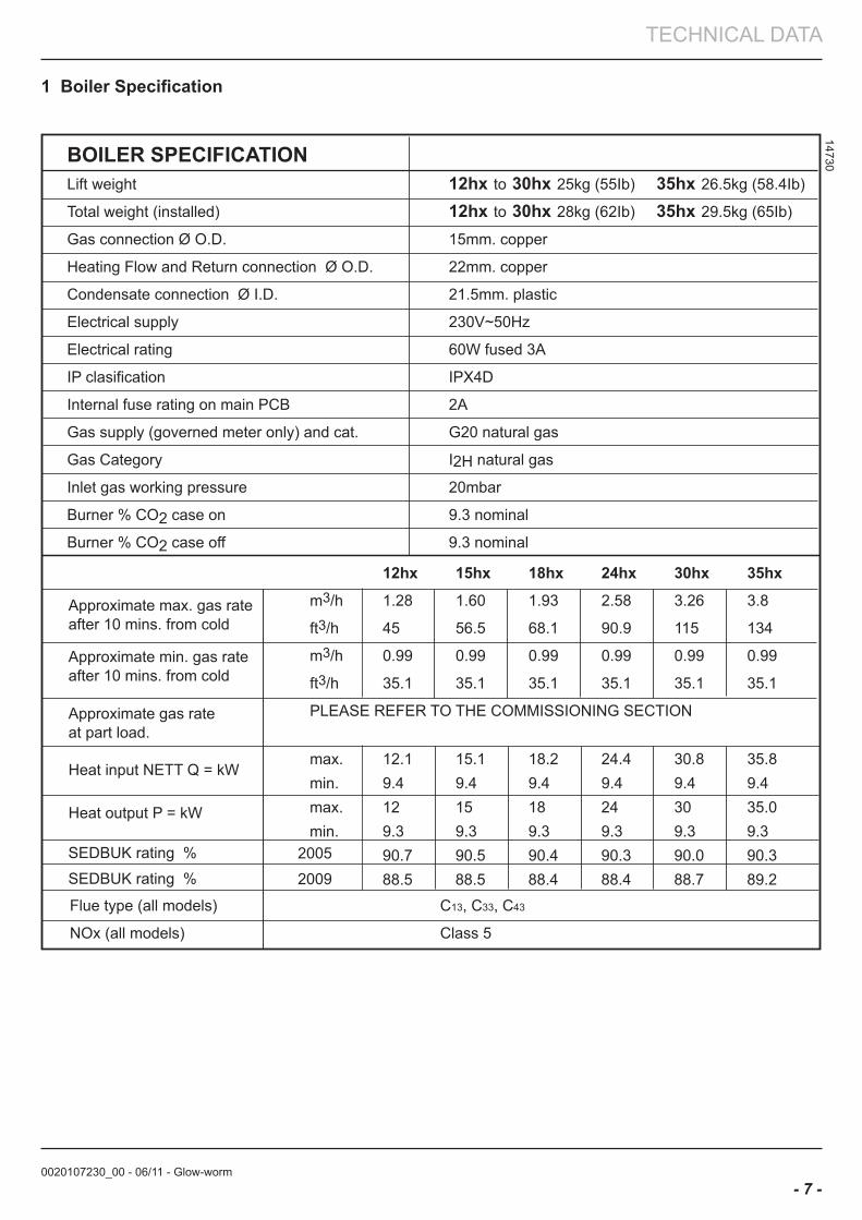
14730BOILER SPECIFICATION Lift weight 12hx to 30hx 25kg (55Ib) 35hx 26.5kg (58.4Ib) Total weight (installed) 12hx to 30hx 28kg (62Ib) 35hx 29.5kg (65Ib) Gas connection Ø O.D. 15mm. copper
Heating Flow and Return connection Ø O.D. 22mm. copper
Condensate connection Ø I.D. 21.5mm. plastic
Electrical supply 230V~50Hz
Electrical rating 60W fused 3A
IP clasification IPX4D
Internal fuse rating on main PCB 2A
Gas supply (governed meter only) and cat. G20 natural gas
Gas Category I2H natural gas
Inlet gas working pressure 20mbar
Burner % CO2 case on 9.3 nominal
Burner % CO2 case off 9.3 nominal
12hx 15hx 18hx 24hx 30hx 35hx
m3/h 1.28 1.60 1.93 2.58 3.26 3.8
ft3/h 45 56.5 68.1 90.9 115 134
m3/h 0.99 0.99 0.99 0.99 0.99 0.99
ft3/h 35.1 35.1 35.1 35.1 35.1 35.1
PLEASE REFER TO THE COMMISSIONING SECTION
max. 12.1 15.1 18.2 24.4 30.8 35.8min. 9.4 9.4 9.4 9.4 9.4 9.4max. 12 15 18 24 30 35.0 min. 9.3 9.3 9.3 9.3 9.3 9.3 90.7 90.5 90.4 90.3 90.0 90.3 88.5 88.5 88.4 88.4 88.7 89.2SEDBUK rating % 2009
Approximate max. gas rate after 10 mins. from cold
Heat input NETT Q = kW
Heat output P = kW
Approximate min. gas rateafter 10 mins. from cold
Approximate gas rateat part load.
SEDBUK rating % 2005
Flue type (all models) C13, C33, C43
NOx (all models) Class 5
1 boiler Specification
0020107230_00 - 06/11 - Glow-worm
INSTALLATION
- 8 -
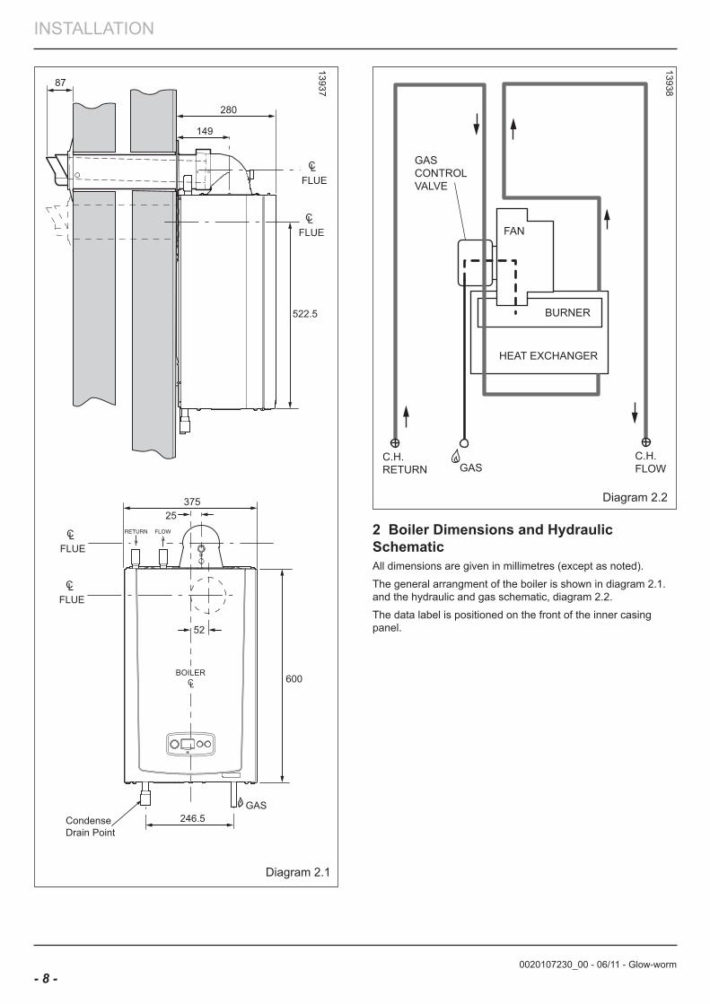
13938
Diagram 2.2
2 boiler Dimensions and Hydraulic SchematicAll dimensions are given in millimetres (except as noted).
The general arrangment of the boiler is shown in diagram 2.1. and the hydraulic and gas schematic, diagram 2.2.
The data label is positioned on the front of the inner casing panel.
13937
Diagram 2.1
0020107230_00 - 06/11 - Glow-worm
INSTALLATION
- 9 -
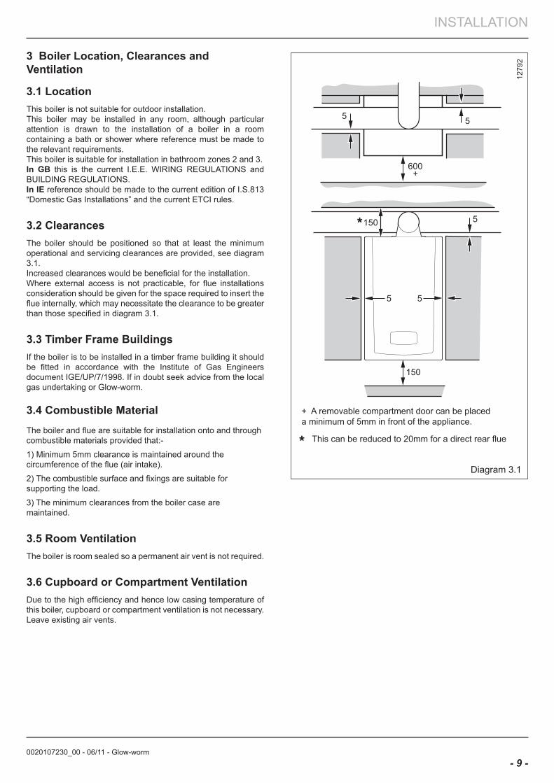
3 boiler location, Clearances and Ventilation
3.1 locationThis boiler is not suitable for outdoor installation.This boiler may be installed in any room, although particular attention is drawn to the installation of a boiler in a room containing a bath or shower where reference must be made to the relevant requirements.This boiler is suitable for installation in bathroom zones 2 and 3. In Gb this is the current I.E.E. WIRING REGULATIONS and BUILDING REGULATIONS.In Ie reference should be made to the current edition of I.S.813 “Domestic Gas Installations” and the current ETCI rules.
3.2 ClearancesThe boiler should be positioned so that at least the minimum operational and servicing clearances are provided, see diagram 3.1.Increased clearances would be beneficial for the installation.Where external access is not practicable, for flue installations consideration should be given for the space required to insert the flue internally, which may necessitate the clearance to be greater than those specified in diagram 3.1.
3.3 Timber frame buildingsIf the boiler is to be installed in a timber frame building it should be fitted in accordance with the Institute of Gas Engineers document IGE/UP/7/1998. If in doubt seek advice from the local gas undertaking or Glow-worm.
3.4 Combustible MaterialThe boiler and flue are suitable for installation onto and through combustible materials provided that:-
1) Minimum 5mm clearance is maintained around the circumference of the flue (air intake).
2) The combustible surface and fixings are suitable for supporting the load.
3) The minimum clearances from the boiler case are maintained.
3.5 Room VentilationThe boiler is room sealed so a permanent air vent is not required.
3.6 Cupboard or Compartment VentilationDue to the high efficiency and hence low casing temperature of this boiler, cupboard or compartment ventilation is not necessary.Leave existing air vents.
1279
2
Diagram 3.1
0020107230_00 - 06/11 - Glow-worm
INSTALLATION
- 10 -
4 evacuation of Combustion Gas
4.1 Regulation
Only flue accessories supplied by Glow-worm must be used.
Different flue outlet configurations can be carried out.
• Consult your supplier for more information about the other possibilities and associated accessories.
44 mm/m
• Standard flue terminal kits have an in-built fall back to the boiler to drain the condensate. These can be fitted level between the appliance and the termination position. All other extended flues must have a fall of at least 44mm/m
The maximum length of the flue outlet is defined according to its type (for example C13).
• Whatever the kind of flue system chosen, observe the minimum distances indicated in the chart below to position the flue terminals.
• To install the flue, refer to the separate flue instruction supplied with your appliance.
• Explain these requirements to the user of the appliance.
a If necessary, you must install terminal protection.
Caution! The connection between the flue elbow and the flue outlet must be sealed.
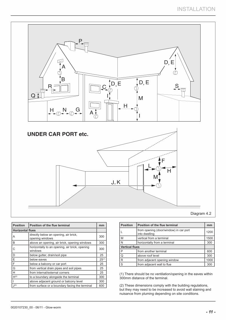
In Gb the minimum acceptable siting dimensions for the terminal from obstructions, other terminals and ventilation openings are shown in diagram overleaf.
In Ie the minimum distances for flue terminal positioning must be those detailed in I.S.813 “Domestic Gas Installations”.
The terminal must be exposed to the external air, allowing free passage of air across it at all times.
Being a condensing boiler some pluming may occur from the flue outlet. This should be taken into consideration when selecting the position for the terminal.
Carports or similar extensions of a roof only, or a roof and one wall, require special consideration with respect to any openings, doors, vents or windows under the roof. Care is required to protect the roof if made of plastic sheeting. If the carport comprises of a roof and two or more walls, seek advice from the local gas supply company before installing the boiler.
If the flue terminal is positioned near a light source insects may enter the flue system. Where safe and practical to do so advise the homeowner to check the flue outlet and clear visible insects from the terminal end.
H* and J* See diagram 4.2. These dimensions comply with the building regulations, but they may need to be increased to avoid wall staining and nuisance from pluming depending on site conditions.
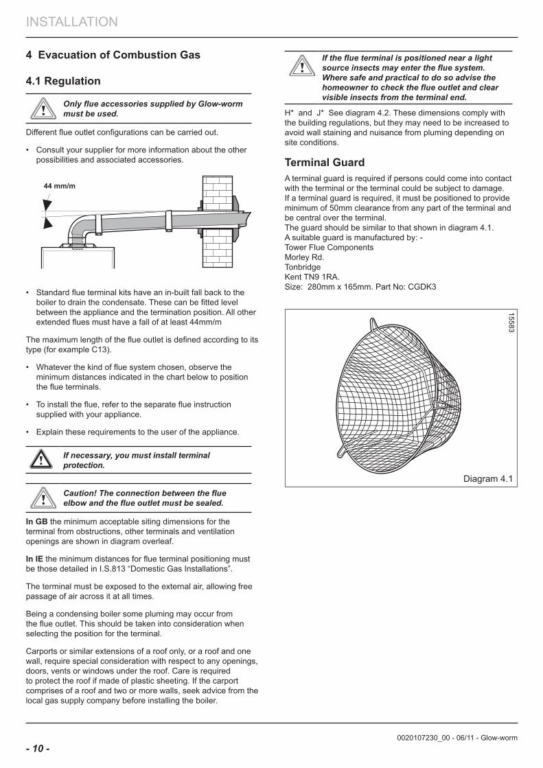
Terminal GuardA terminal guard is required if persons could come into contact with the terminal or the terminal could be subject to damage.If a terminal guard is required, it must be positioned to provide minimum of 50mm clearance from any part of the terminal and be central over the terminal.The guard should be similar to that shown in diagram 4.1.A suitable guard is manufactured by: -Tower Flue ComponentsMorley Rd.TonbridgeKent TN9 1RA.Size: 280mm x 165mm. Part No: CGDK3
Diagram 4.1
15583
0020107230_00 - 06/11 - Glow-worm
INSTALLATION
- 11 -
Position Position of the flue terminal mmHorizontal flues
A directly below an opening, air brick,opening windows 300
B above an opening, air brick, opening windows 300
C horizontally to an opening, air brick, opening windows 300
D below gutter, drain/soil pipe 25E below eaves 25(1)
F below a balcony or car port 25G from vertical drain pipes and soil pipes 25H from internal/external corners 25H(2) to a boundary alongside the terminal 300I above adjacent ground or balcony level 300J(2) from surface or a boundary facing the terminal 600
Position Position of the flue terminal mm
L from opening (door/window) in car portinto dwelling 1200
M vertical from a terminal 1500N horizontally from a terminal 300Vertical fluesP from another terminal 600Q above roof level 300R from adjacent opening window 1000S from adjacent wall to flue 300
(1) There should be no ventilation/opening in the eaves within 300mm distance of the terminal.
(2) These dimensions comply with the building regulations, but they may need to be increased to avoid wall staining and nuisance from pluming depending on site conditions.
Diagram 4.2
0020107230_00 - 06/11 - Glow-worm
INSTALLATION
- 12 -
4.2 flue configuration description
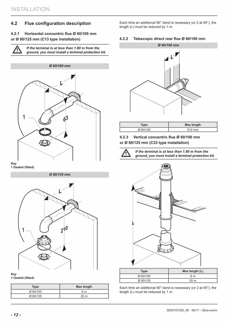
4.2.1 Horizontal concentric flue Ø 60/100 mm or Ø 80/125 mm (C13 type installation)
a If the terminal is at less than 1.80 m from the ground, you must install a terminal protection kit.
Ø 60/100 mm
L
631
Key1 Gasket (fitted)
Ø 80/125 mm
L
1
Key1 Gasket (fitted)
Type Max lengthØ 60/100 8 mØ 80/125 20 m
Type Max lengthØ 60/100 512 mm
4.2.3 Vertical concentric flue Ø 60/100 mm or Ø 80/125 mm (C33 type installation)
a If the terminal is at less than 1.80 m from the ground, you must install a terminal protection kit.
L
Type Max length (l)Ø 60/100 8 mØ 80/125 20 m
Each time an additional 90° bend is necessary (or 2 at 45°), the length (L) must be reduced by 1 m.
L
Each time an additional 90° bend is necessary (or 2 at 45°), the length (L) must be reduced by 1 m.
4.2.2 Telescopic direct rear flue Ø 60/100 mmØ 60/100 mm
0020107230_00 - 06/11 - Glow-worm
INSTALLATION
- 13 -
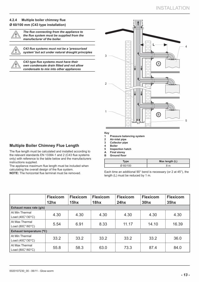
4.2.4 Multiple boiler chimney flue Ø 60/100 mm (C43 type installation)
The flue connecting from the appliance to the flue system must be supplied from the manufacturer of the boiler.
C43 flue systems must not be a 'pressurised system' but act under natural draught principles
C43 type flue systems must have their own condensate drain fitted and not allow condensate to mix into other appliances
Multiple boiler Chimney flue lengthThe flue length must be calculated and installed according to the relevant standards EN 13384-1 and 2 (C43 flue systems only) with reference to the table below and the manufacturers instructions supplied. The appliance maximum flue length must be included when calculating the overall design of the flue system.noTe: The horizontal flue terminal must be removed.
L
B
A
1
2
3
4
5
Key1 Pressure balancing system2 air-inlet pipe 3 Collector pipe4 boiler5 Inspection hatcha final storeyb Ground floor
Type Max length (l)Ø 60/100 8 m
Each time an additional 90° bend is necessary (or 2 at 45°), the length (L) must be reduced by 1 m.
flexicom12hx
flexicom15hx
flexicom18hx
flexicom24hx
flexicom30hx
flexicom35hx
exhaust mass rate (g/s)At Min ThermalLoad (40C°/30°C) 4.30 4.30 4.30 4.30 4.30 4.30
At Max ThermalLoad (80C°/60°C) 5.54 6.91 8.33 11.17 14.10 16.39
exhaust temperature (ºC)At Min ThermalLoad (40C°/30°C) 33.2 33.2 33.2 33.2 33.2 36.0
At Max ThermalLoad (80C°/60°C) 55.8 58.3 63.0 73.3 87.4 84.0
0020107230_00 - 06/11 - Glow-worm
INSTALLATION
- 14 -
0 5 10 15 20 25 30
Flow Rate (litres/min)
24kW
30kW
Pres
sure
Los
s (m
etre
s)
15kW
35kW
5 Water Systems - General
5.1 GeneralThis boiler is designed to provide central heating from a fully pumped open vented or sealed water system and domestic hot water using a fully indirect vented or unvented cylinder.
5.2 Draining PointsDraining taps must be provided at all low points of the system, which will allow the entire system to be drained.Draining taps shall be to the current issue of BS2879.
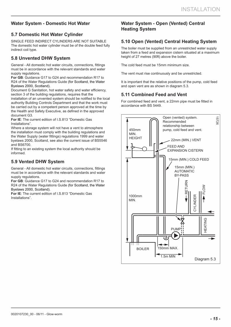
5.3 Pump The pump should be fitted on the flow pipe from the boiler and have isolating valves each side.A variable duty pump should be set to give a temperature difference of no greater than 20oC between the flow and return, with the thermostat set at “MAX”, which is about 80oC, to give a flow rate as given in the table.See chart for pressure loss of the boiler, diagram 5.1.High resistance microbore systems may require a higher duty pump.
5.4 flow RateIf it is necessary to alter the flow rate, the system can be fitted with a lockable balancing valve in the main flow or return pipes shown in diagram 5.4. The flow rate through the boiler must not be allowed to fall below that given in diagram 5.2.
5.5 bypassA system bypass is required and should be fitted at least 1.5 metres away from the boiler, refer to the current issue of the central heating system specifications (CHeSS).
5.6 Water Treatmentexisting system- It is ESSENTIAL that prior to installing the new boiler the system is thoroughly flushed.
new system- For optimum performance after installation, the boiler and its associated central heating system should also be flushed.
Flushing should be carried out in accordance with BS7593: 2006 using a cleanser such as Sentinel X300 or X400, Fernox Restorer or Salamander corrosion guard cleaner.
IMPoRTanT: Ensure all cleanser is removed from the whole system before adding an inhibitor.For long-term corrosion protection, after flushing, an inhibitor should be used, refer to the current issue of BS 5449 and BS 7593 on the use of inhibitors in central heating systems. Examples are Sentinel X100 Fernox Protector or Salamander corrosion guard inhibitor.
Diagram 5.2
14401
Diagram 5.1
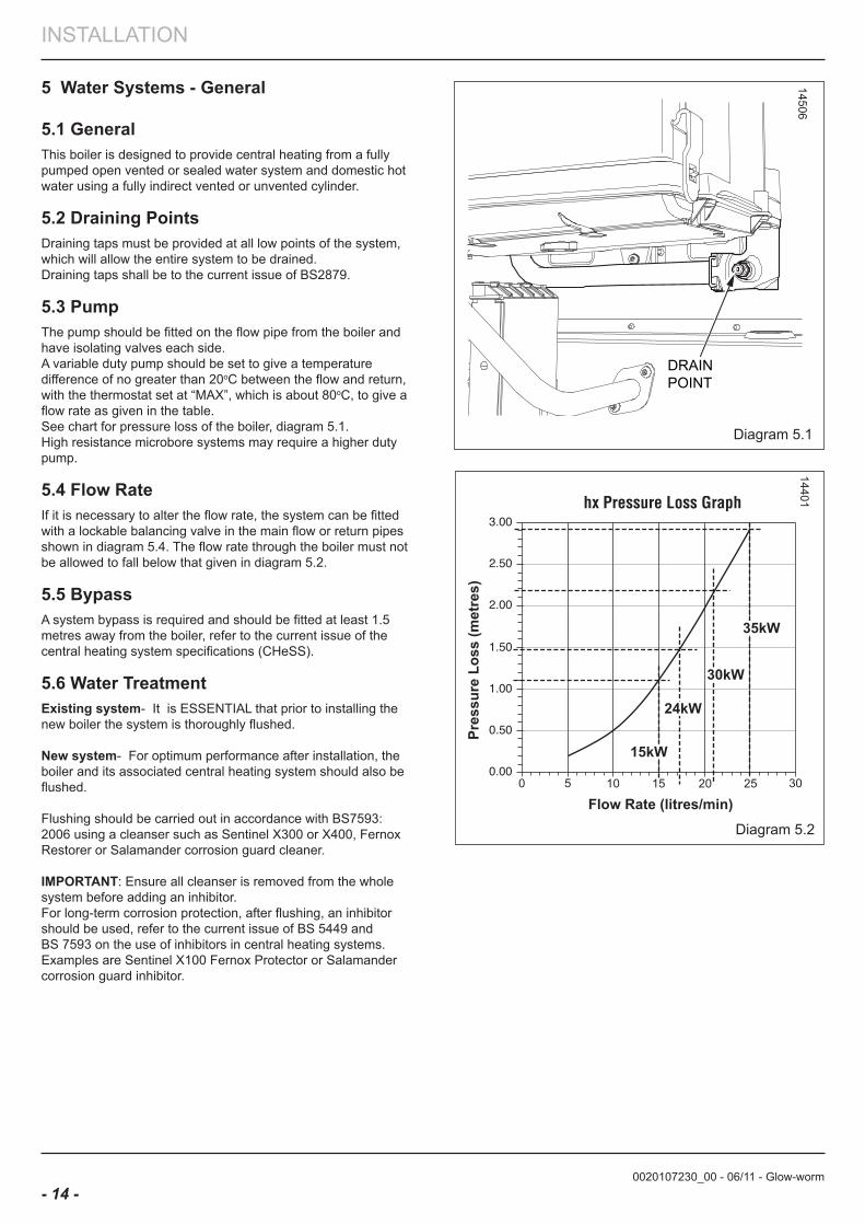
14506
DRAINPOINT
0020107230_00 - 06/11 - Glow-worm
INSTALLATION
- 15 -
Water System - Domestic Hot Water
5.7 Domestic Hot Water CylinderSINGLE FEED INDIRECT CYLINDERS ARE NOT SUITABLEThe domestic hot water cylinder must be of the double feed fully indirect coil type.
5.8 Unvented DHW SystemGeneral - All domestic hot water circuits, connections, fittings must be in accordance with the relevant standards and water supply regulations.for Gb: Guidance G17 to G24 and recommendation R17 to R24 of the Water Regulations Guide (for Scotland, the Water Byelaws 2000, Scotland).Document G Sanitation, hot water safety and water efficiency, section 3 of the building regulations, requires that the installation of an unvented system should be notified to the local authority Building Controls Department and that the work must be carried out by a competent person approved at the time by the Health and Safety Executive, as defined in the approved document G3.for Ie: The current edition of I.S.813 “Domestic Gas Installations”.Where a storage system will not have a vent to atmosphere the installation must comply with the building regulations and the Water Supply (water fittings) regulations 1999 and water byelaws 2000, Scotland, see also the current issue of BS5546 and BS6700.If fitting to an existing system the local authority should be informed.
5.9 Vented DHW SystemGeneral - All domestic hot water circuits, connections, fittings must be in accordance with the relevant standards and water supply regulations.for Gb: Guidance G17 to G24 and recommendation R17 to R24 of the Water Regulations Guide (for Scotland, the Water Byelaws 2000, Scotland).for Ie: The current edition of I.S.813 “Domestic Gas Installations”.
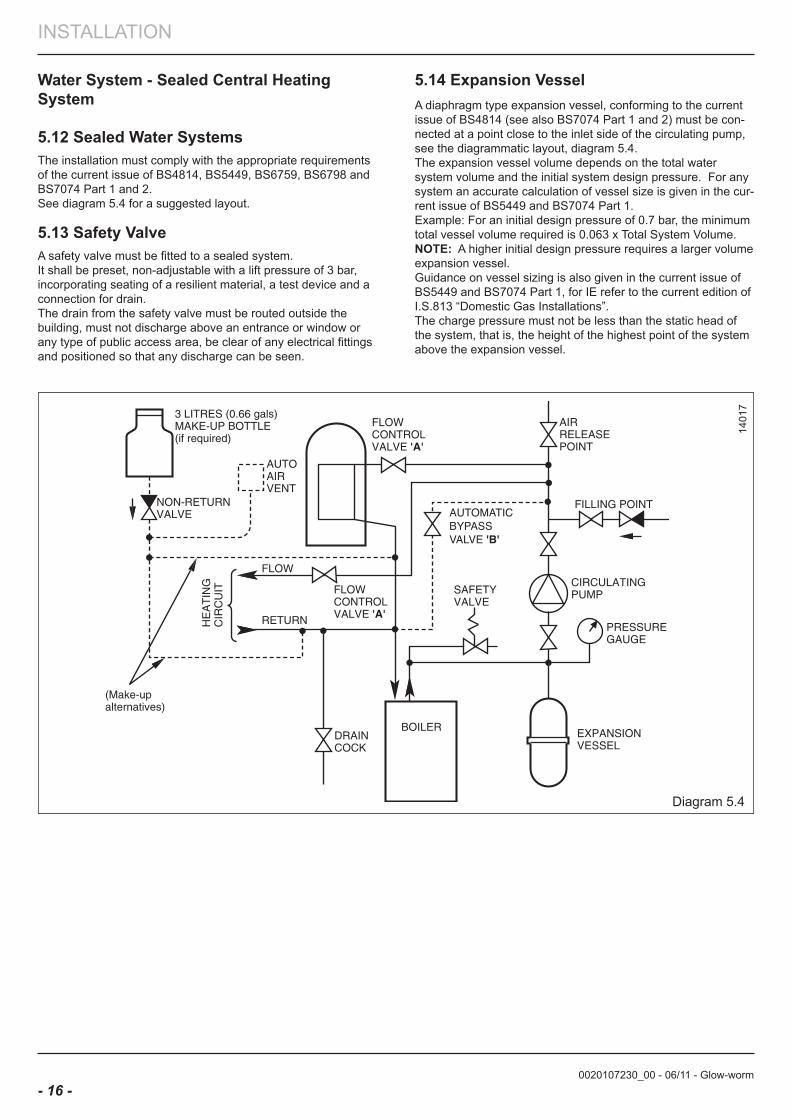
Diagram 5.3
15726
Water System - open (Vented) Central Heating System
5.10 open (Vented) Central Heating SystemThe boiler must be supplied from an unrestricted water supply taken from a feed and expansion cistern situated at a maximum height of 27 metres (90ft) above the boiler.
The cold feed must be 15mm minimum size.
The vent must rise continuously and be unrestricted.
It is important that the relative positions of the pump, cold feed and open vent are as shown in diagram 5.3.
5.11 Combined feed and VentFor combined feed and vent, a 22mm pipe must be fitted in accordance with BS 5449.
0020107230_00 - 06/11 - Glow-worm
INSTALLATION
- 16 -
Water System - Sealed Central Heating System
5.12 Sealed Water SystemsThe installation must comply with the appropriate requirements of the current issue of BS4814, BS5449, BS6759, BS6798 and BS7074 Part 1 and 2.See diagram 5.4 for a suggested layout.
5.13 Safety ValveA safety valve must be fitted to a sealed system.It shall be preset, non-adjustable with a lift pressure of 3 bar, incorporating seating of a resilient material, a test device and a connection for drain.The drain from the safety valve must be routed outside the building, must not discharge above an entrance or window or any type of public access area, be clear of any electrical fittings and positioned so that any discharge can be seen.
Diagram 5.4
1401
7
5.14 expansion VesselA diaphragm type expansion vessel, conforming to the current issue of BS4814 (see also BS7074 Part 1 and 2) must be con-nected at a point close to the inlet side of the circulating pump, see the diagrammatic layout, diagram 5.4.The expansion vessel volume depends on the total water system volume and the initial system design pressure. For any system an accurate calculation of vessel size is given in the cur-rent issue of BS5449 and BS7074 Part 1.Example: For an initial design pressure of 0.7 bar, the minimum total vessel volume required is 0.063 x Total System Volume.noTe: A higher initial design pressure requires a larger volume expansion vessel.Guidance on vessel sizing is also given in the current issue of BS5449 and BS7074 Part 1, for IE refer to the current edition of I.S.813 “Domestic Gas Installations”.The charge pressure must not be less than the static head of the system, that is, the height of the highest point of the system above the expansion vessel.
0020107230_00 - 06/11 - Glow-worm
INSTALLATION
- 17 -
TEMPORARYCONNECTION
HOSEUNION
HOSEUNION
SUPPLYPIPE
CONTROLVALVE
CONTROLVALVE
DOUBLECHECKVALVE
HEATINGCIRCUIT
DRAINPOINT
SUPPLYPIPE
AIR GAP
TUNDISH
CONTROLVALVE
CONTROLVALVE
TYPE CA BACKFLOWPREVENTION DEVICE
BOILER
RETURNFLOW
BOILER
RETURNFLOW
HEATINGCIRCUIT
DRAINPOINT
Method 1
Method 2
Diagram 5.5
11680
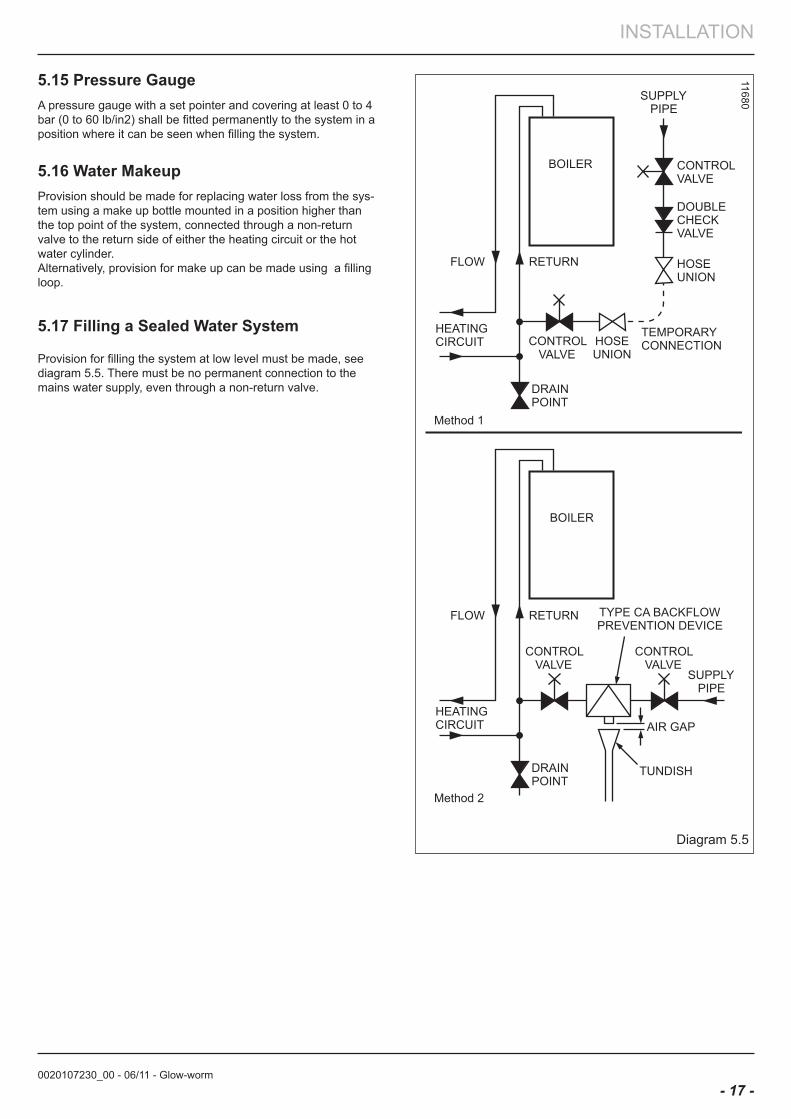
5.15 Pressure GaugeA pressure gauge with a set pointer and covering at least 0 to 4 bar (0 to 60 lb/in2) shall be fitted permanently to the system in a position where it can be seen when filling the system.
5.16 Water MakeupProvision should be made for replacing water loss from the sys-tem using a make up bottle mounted in a position higher than the top point of the system, connected through a non-return valve to the return side of either the heating circuit or the hot water cylinder.Alternatively, provision for make up can be made using a filling loop.
5.17 filling a Sealed Water System
Provision for filling the system at low level must be made, see diagram 5.5. There must be no permanent connection to the mains water supply, even through a non-return valve.
0020107230_00 - 06/11 - Glow-worm
INSTALLATION
- 18 -
6 Installation Preparation
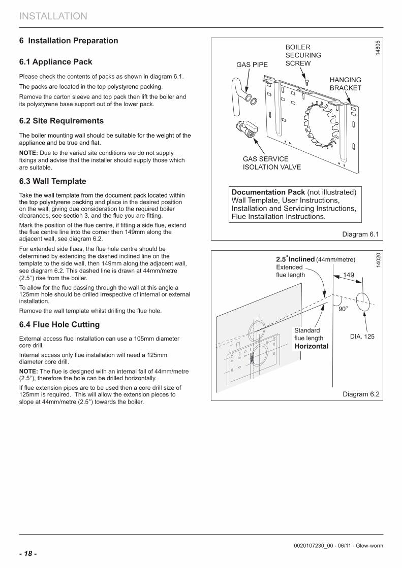
6.1 appliance PackPlease check the contents of packs as shown in diagram 6.1.
The packs are located in the top polystyrene packing.
Remove the carton sleeve and top pack then lift the boiler and its polystyrene base support out of the lower pack.
6.2 Site RequirementsThe boiler mounting wall should be suitable for the weight of the appliance and be true and flat.
noTe: Due to the varied site conditions we do not supply fixings and advise that the installer should supply those which are suitable.
6.3 Wall TemplateTake the wall template from the document pack located within the top polystyrene packing and place in the desired position on the wall, giving due consideration to the required boiler clearances, see section 3, and the flue you are fitting.Mark the position of the flue centre, if fitting a side flue, extend the flue centre line into the corner then 149mm along the adjacent wall, see diagram 6.2.
For extended side flues, the flue hole centre should be determined by extending the dashed inclined line on the template to the side wall, then 149mm along the adjacent wall, see diagram 6.2. This dashed line is drawn at 44mm/metre (2.5°) rise from the boiler.To allow for the flue passing through the wall at this angle a 125mm hole should be drilled irrespective of internal or external installation. Remove the wall template whilst drilling the flue hole.
6.4 flue Hole CuttingExternal access flue installation can use a 105mm diameter core drill.Internal access only flue installation will need a 125mm diameter core drill.noTe: The flue is designed with an internal fall of 44mm/metre (2.5°), therefore the hole can be drilled horizontally.If flue extension pipes are to be used then a core drill size of 125mm is required. This will allow the extension pieces to slope at 44mm/metre (2.5°) towards the boiler.
1402
0
Diagram 6.2
Diagram 6.1
1480
5
Documentation Pack (not illustrated)Wall Template, User Instructions, Installation and Servicing Instructions,Flue Installation Instructions.
BOILER SECURINGSCREW
0020107230_00 - 06/11 - Glow-worm
INSTALLATION
- 19 -
Diagram 7.1
1480
67 boiler fixing
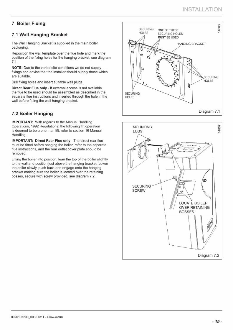
7.1 Wall Hanging bracketThe Wall Hanging Bracket is supplied in the main boiler packaging.
Reposition the wall template over the flue hole and mark the position of the fixing holes for the hanging bracket, see diagram 7.1.
noTe: Due to the varied site conditions we do not supply fixings and advise that the installer should supply those which are suitable.
Drill fixing holes and insert suitable wall plugs.
Direct Rear flue only - If external access is not available the flue to be used should be assembled as described in the separate flue instructions and inserted through the hole in the wall before fitting the wall hanging bracket.
7.2 boiler HangingIMPoRTanT: With regards to the Manual Handling Operations, 1992 Regulations, the following lift operation is deemed to be a one man lift, refer to section 16 Manual Handling.
IMPoRTanT: Direct Rear flue only - The direct rear flue must be fitted before hanging the boiler, refer to the separate flue instructions, and the rear outlet cover plate should be removed.
Lifting the boiler into position, lean the top of the boiler slightly to the wall and position just above the hanging bracket. Lower the boiler slowly, push back and engage onto the hanging bracket making sure the boiler is located over the retaining bosses, secure with screw provided, see diagram 7.2.
Diagram 7.2
1480
7
SECURINGSCREW
0020107230_00 - 06/11 - Glow-worm
INSTALLATION
- 20 -
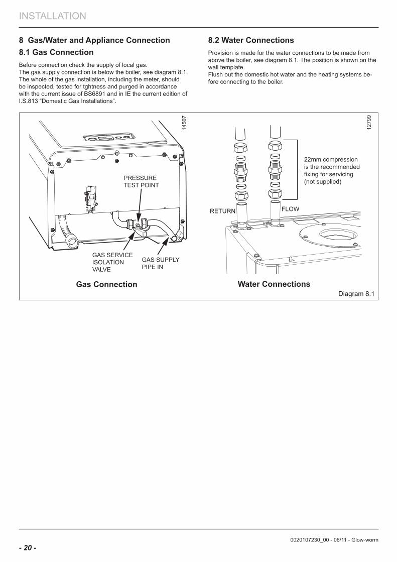
Diagram 8.1
8 Gas/Water and appliance Connection8.1 Gas ConnectionBefore connection check the supply of local gas.The gas supply connection is below the boiler, see diagram 8.1.The whole of the gas installation, including the meter, should be inspected, tested for tghtness and purged in accordance with the current issue of BS6891 and in IE the current edition of I.S.813 “Domestic Gas Installations”.
RETURN FLOW
22mm compressionis the recommendedfixing for servicing(not supplied)
Gas Connection Water Connections
1279
9
1450
7
8.2 Water ConnectionsProvision is made for the water connections to be made from above the boiler, see diagram 8.1. The position is shown on the wall template. Flush out the domestic hot water and the heating systems be-fore connecting to the boiler.
GAS SERVICEISOLATIONVALVE
GAS SUPPLYPIPE IN
PRESSURETEST POINT
0020107230_00 - 06/11 - Glow-worm
INSTALLATION
- 21 -
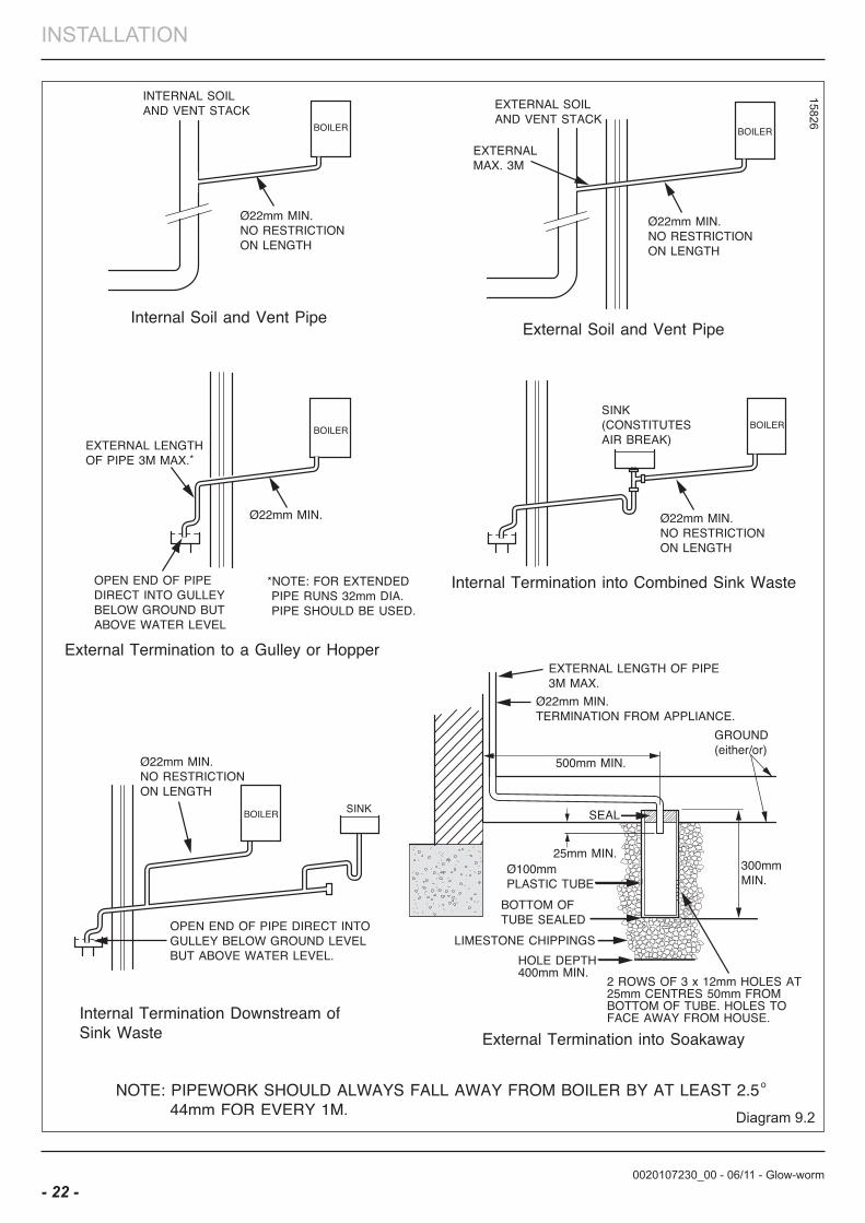
9 Condensate Connections
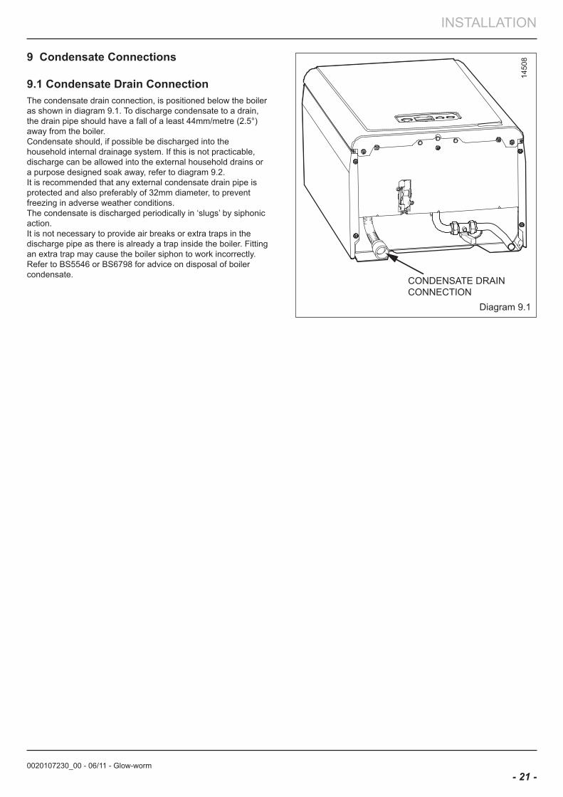
9.1 Condensate Drain ConnectionThe condensate drain connection, is positioned below the boiler as shown in diagram 9.1. To discharge condensate to a drain, the drain pipe should have a fall of a least 44mm/metre (2.5°) away from the boiler.Condensate should, if possible be discharged into the household internal drainage system. If this is not practicable, discharge can be allowed into the external household drains or a purpose designed soak away, refer to diagram 9.2.It is recommended that any external condensate drain pipe is protected and also preferably of 32mm diameter, to prevent freezing in adverse weather conditions.The condensate is discharged periodically in ‘slugs’ by siphonic action.It is not necessary to provide air breaks or extra traps in the discharge pipe as there is already a trap inside the boiler. Fitting an extra trap may cause the boiler siphon to work incorrectly. Refer to BS5546 or BS6798 for advice on disposal of boiler condensate.
1450
8
Diagram 9.1
CONDENSATE DRAINCONNECTION
0020107230_00 - 06/11 - Glow-worm
INSTALLATION
- 22 -
15826
Diagram 9.2
0020107230_00 - 06/11 - Glow-worm
INSTALLATION
- 23 -
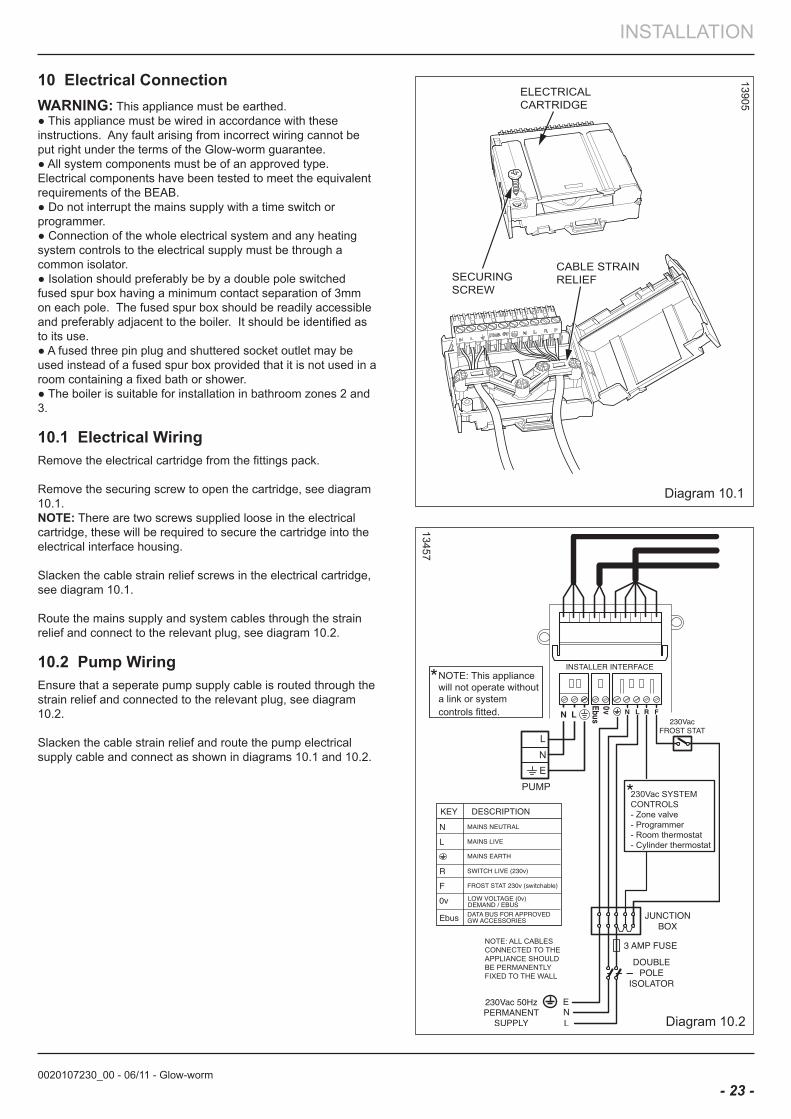
10 electrical ConnectionWaRnInG: This appliance must be earthed. ● This appliance must be wired in accordance with these instructions. Any fault arising from incorrect wiring cannot be put right under the terms of the Glow-worm guarantee.● All system components must be of an approved type.Electrical components have been tested to meet the equivalent requirements of the BEAB.● Do not interrupt the mains supply with a time switch or programmer.● Connection of the whole electrical system and any heating system controls to the electrical supply must be through a common isolator.● Isolation should preferably be by a double pole switched fused spur box having a minimum contact separation of 3mm on each pole. The fused spur box should be readily accessible and preferably adjacent to the boiler. It should be identified as to its use.● A fused three pin plug and shuttered socket outlet may be used instead of a fused spur box provided that it is not used in a room containing a fixed bath or shower.● The boiler is suitable for installation in bathroom zones 2 and 3.
10.1 electrical WiringRemove the electrical cartridge from the fittings pack.
Remove the securing screw to open the cartridge, see diagram 10.1.noTe: There are two screws supplied loose in the electrical cartridge, these will be required to secure the cartridge into the electrical interface housing.
Slacken the cable strain relief screws in the electrical cartridge, see diagram 10.1.
Route the mains supply and system cables through the strain relief and connect to the relevant plug, see diagram 10.2.
10.2 Pump WiringEnsure that a seperate pump supply cable is routed through the strain relief and connected to the relevant plug, see diagram 10.2.
Slacken the cable strain relief and route the pump electrical supply cable and connect as shown in diagrams 10.1 and 10.2.
ELECTRICALCARTRIDGE
CABLE STRAINRELIEFSECURING
SCREW
Diagram 10.1
13905
Diagram 10.2
13457
0020107230_00 - 06/11 - Glow-worm
INSTALLATION
- 24 -
13906
ELECTRICALCARTRIDGE
FIXINGSCREWS
Diagram 10.3
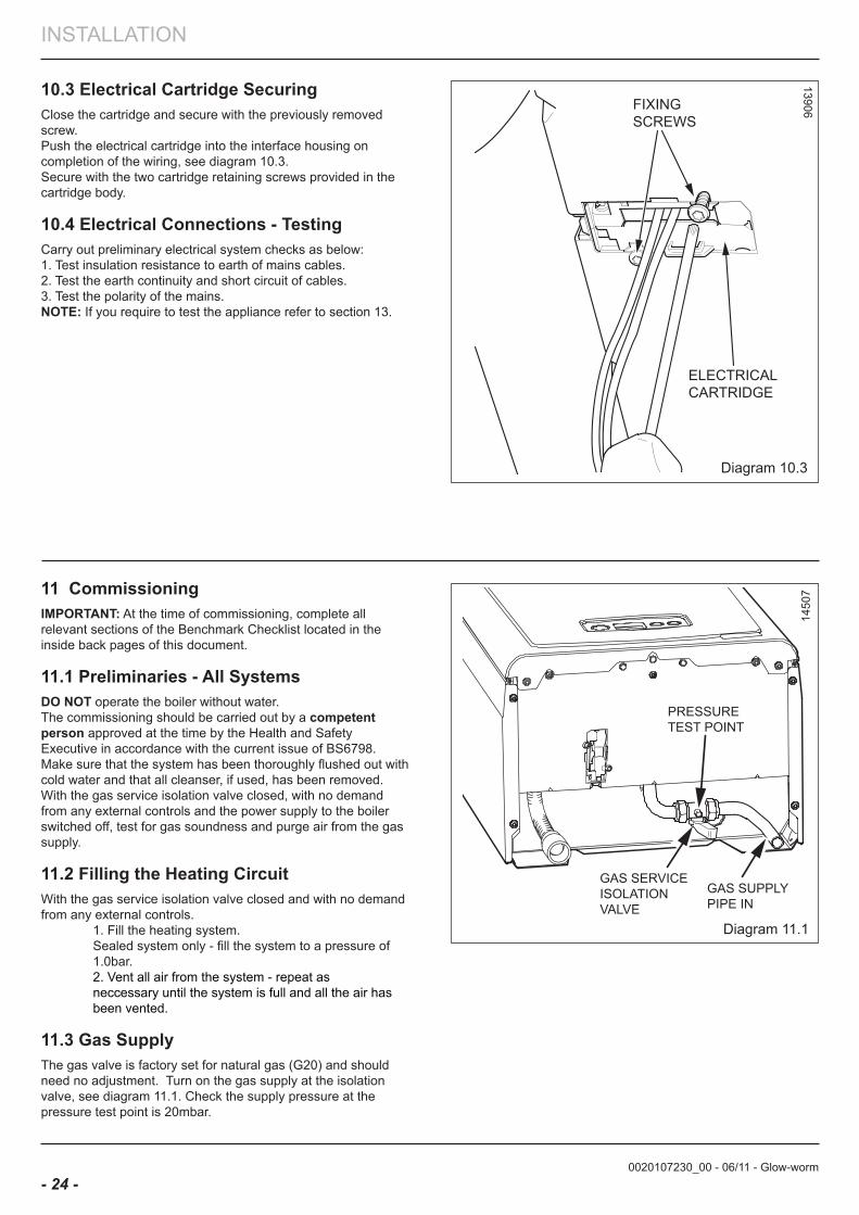
10.3 electrical Cartridge SecuringClose the cartridge and secure with the previously removed screw.Push the electrical cartridge into the interface housing on completion of the wiring, see diagram 10.3. Secure with the two cartridge retaining screws provided in the cartridge body.
10.4 electrical Connections - TestingCarry out preliminary electrical system checks as below:1. Test insulation resistance to earth of mains cables.2. Test the earth continuity and short circuit of cables.3. Test the polarity of the mains.noTe: If you require to test the appliance refer to section 13.
11 CommissioningIMPoRTanT: At the time of commissioning, complete all relevant sections of the Benchmark Checklist located in the inside back pages of this document.
11.1 Preliminaries - all Systems Do noT operate the boiler without water. The commissioning should be carried out by a competent person approved at the time by the Health and Safety Executive in accordance with the current issue of BS6798.Make sure that the system has been thoroughly flushed out with cold water and that all cleanser, if used, has been removed.With the gas service isolation valve closed, with no demand from any external controls and the power supply to the boiler switched off, test for gas soundness and purge air from the gas supply.
11.2 filling the Heating CircuitWith the gas service isolation valve closed and with no demand from any external controls. 1. Fill the heating system. Sealed system only - fill the system to a pressure of 1.0bar. 2. Vent all air from the system - repeat as neccessary until the system is full and all the air has been vented.
11.3 Gas SupplyThe gas valve is factory set for natural gas (G20) and should need no adjustment. Turn on the gas supply at the isolation valve, see diagram 11.1. Check the supply pressure at the pressure test point is 20mbar.
Diagram 11.1
1450
7
GAS SERVICEISOLATIONVALVE
GAS SUPPLYPIPE IN
PRESSURETEST POINT
0020107230_00 - 06/11 - Glow-worm
INSTALLATION
- 25 -
Commissioning should only be carried out by a competent person approved at the time by the Health and Safety Executive.
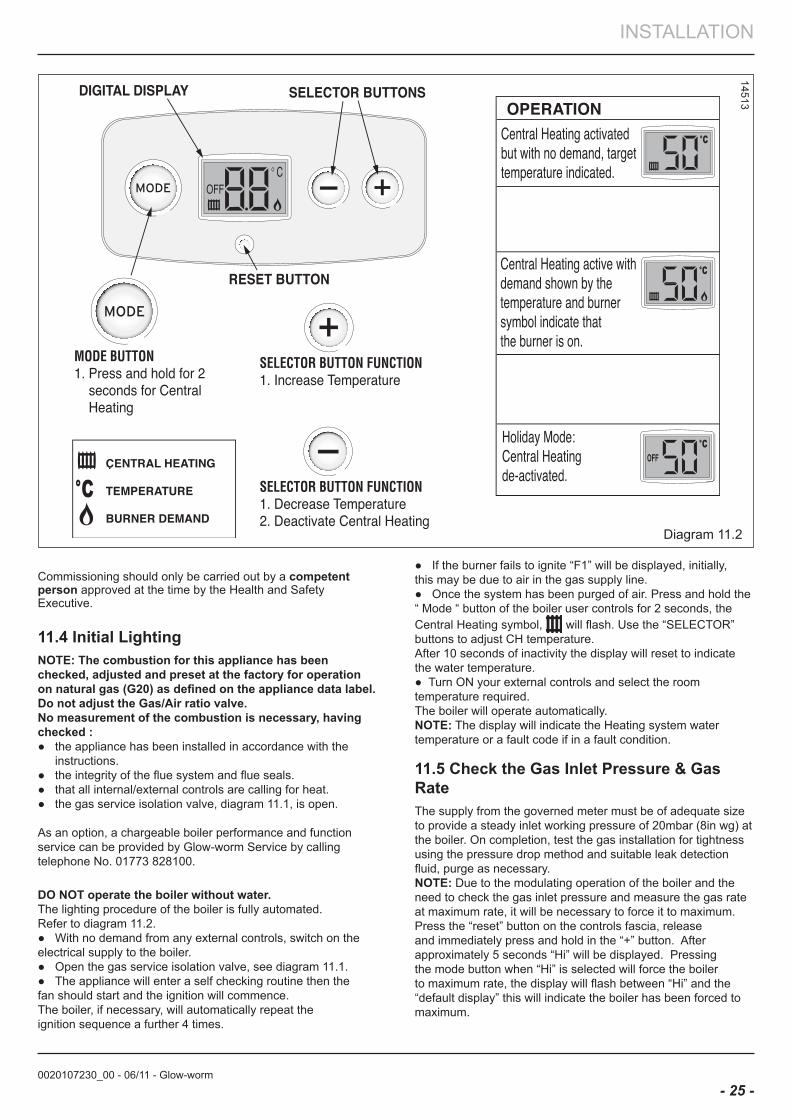
11.4 Initial lightingnoTe: The combustion for this appliance has been checked, adjusted and preset at the factory for operation on natural gas (G20) as defined on the appliance data label.Do not adjust the Gas/air ratio valve. no measurement of the combustion is necessary, having checked :● the appliance has been installed in accordance with the instructions.● the integrity of the flue system and flue seals.● that all internal/external controls are calling for heat.● the gas service isolation valve, diagram 11.1, is open. As an option, a chargeable boiler performance and function service can be provided by Glow-worm Service by calling telephone No. 01773 828100.
Do noT operate the boiler without water. The lighting procedure of the boiler is fully automated.Refer to diagram 11.2.● With no demand from any external controls, switch on the electrical supply to the boiler.● Open the gas service isolation valve, see diagram 11.1. ● The appliance will enter a self checking routine then the fan should start and the ignition will commence.The boiler, if necessary, will automatically repeat the ignition sequence a further 4 times.
Diagram 11.2
14513
● If the burner fails to ignite “F1” will be displayed, initially, this may be due to air in the gas supply line.● Once the system has been purged of air. Press and hold the “ Mode “ button of the boiler user controls for 2 seconds, the Central Heating symbol, will flash. Use the “SELECTOR” buttons to adjust CH temperature. After 10 seconds of inactivity the display will reset to indicate the water temperature. ● Turn ON your external controls and select the room temperature required.The boiler will operate automatically.noTe: The display will indicate the Heating system water temperature or a fault code if in a fault condition.
11.5 Check the Gas Inlet Pressure & Gas Rate The supply from the governed meter must be of adequate size to provide a steady inlet working pressure of 20mbar (8in wg) at the boiler. On completion, test the gas installation for tightness using the pressure drop method and suitable leak detection fluid, purge as necessary.noTe: Due to the modulating operation of the boiler and the need to check the gas inlet pressure and measure the gas rate at maximum rate, it will be necessary to force it to maximum. Press the “reset” button on the controls fascia, release and immediately press and hold in the “+” button. After approximately 5 seconds “Hi” will be displayed. Pressing the mode button when “Hi” is selected will force the boiler to maximum rate, the display will flash between “Hi” and the “default display” this will indicate the boiler has been forced to maximum.
MODE
MODE
0020107230_00 - 06/11 - Glow-worm
INSTALLATION
- 26 -
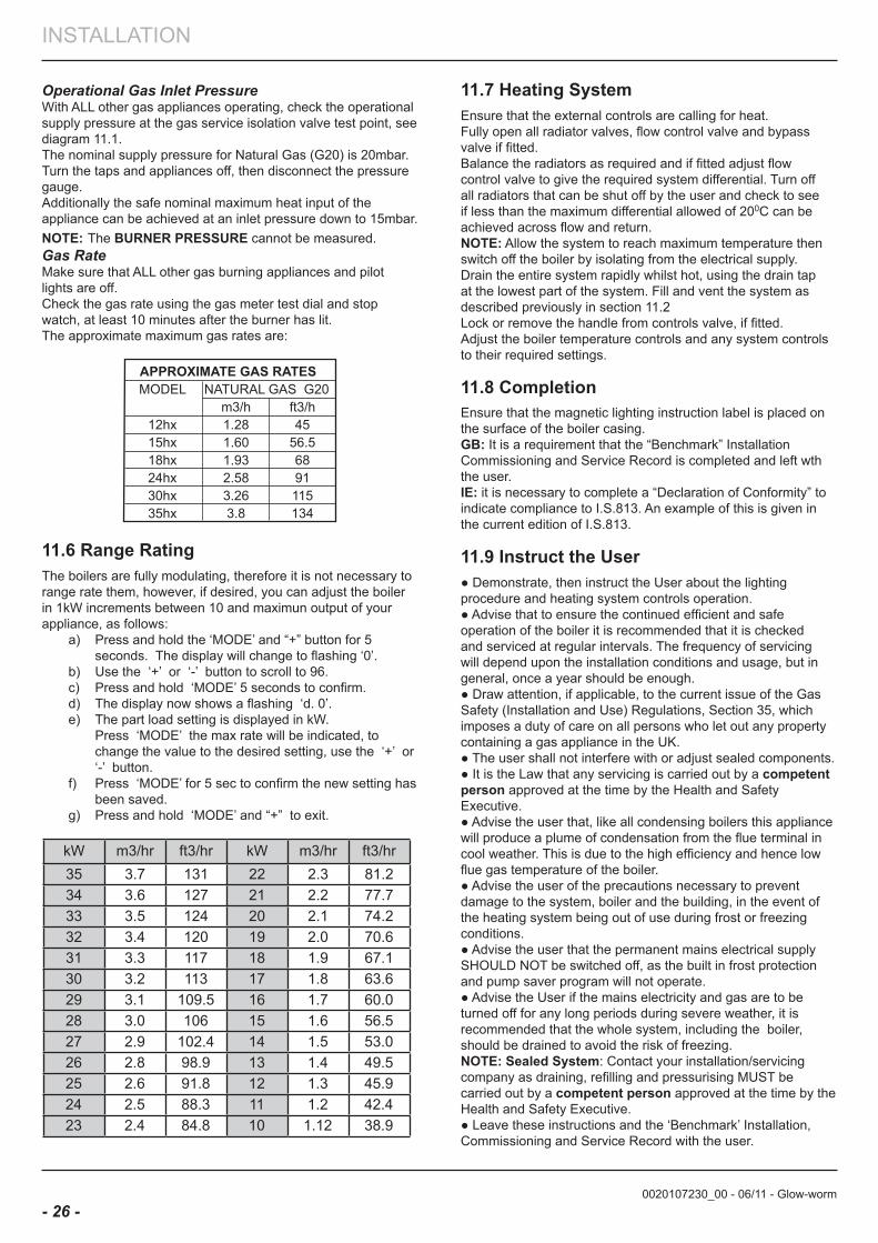
Operational Gas Inlet PressureWith ALL other gas appliances operating, check the operational supply pressure at the gas service isolation valve test point, see diagram 11.1.The nominal supply pressure for Natural Gas (G20) is 20mbar.Turn the taps and appliances off, then disconnect the pressure gauge. Additionally the safe nominal maximum heat input of the appliance can be achieved at an inlet pressure down to 15mbar.noTe: The bURneR PReSSURe cannot be measured. Gas RateMake sure that ALL other gas burning appliances and pilot lights are off. Check the gas rate using the gas meter test dial and stop watch, at least 10 minutes after the burner has lit.The approximate maximum gas rates are:
APPROXIMATE GAS RATES MODEL NATURAL GAS G20 m3/h ft3/h 12hx 1.28 45 15hx 1.60 56.5 18hx 1.93 68 24hx 2.58 91 30hx 3.26 115 35hx 3.8 134
11.6 Range RatingThe boilers are fully modulating, therefore it is not necessary to range rate them, however, if desired, you can adjust the boiler in 1kW increments between 10 and maximun output of your appliance, as follows:
a) Press and hold the ‘MODE’ and “+” button for 5 seconds. The display will change to flashing ‘0’.
b) Use the ‘+’ or ‘-’ button to scroll to 96.c) Press and hold ‘MODE’ 5 seconds to confirm.d) The display now shows a flashing ‘d. 0’. e) The part load setting is displayed in kW. Press ‘MODE’ the max rate will be indicated, to
change the value to the desired setting, use the ‘+’ or ‘-’ button.
f) Press ‘MODE’ for 5 sec to confirm the new setting has been saved.
g) Press and hold ‘MODE’ and “+” to exit.
kW m3/hr ft3/hr kW m3/hr ft3/hr35 3.7 131 22 2.3 81.234 3.6 127 21 2.2 77.733 3.5 124 20 2.1 74.232 3.4 120 19 2.0 70.631 3.3 117 18 1.9 67.130 3.2 113 17 1.8 63.629 3.1 109.5 16 1.7 60.028 3.0 106 15 1.6 56.527 2.9 102.4 14 1.5 53.026 2.8 98.9 13 1.4 49.525 2.6 91.8 12 1.3 45.924 2.5 88.3 11 1.2 42.423 2.4 84.8 10 1.12 38.9
11.7 Heating SystemEnsure that the external controls are calling for heat. Fully open all radiator valves, flow control valve and bypass valve if fitted.Balance the radiators as required and if fitted adjust flow control valve to give the required system differential. Turn off all radiators that can be shut off by the user and check to see if less than the maximum differential allowed of 200C can be achieved across flow and return.noTe: Allow the system to reach maximum temperature then switch off the boiler by isolating from the electrical supply.Drain the entire system rapidly whilst hot, using the drain tap at the lowest part of the system. Fill and vent the system as described previously in section 11.2Lock or remove the handle from controls valve, if fitted.Adjust the boiler temperature controls and any system controls to their required settings.
11.8 CompletionEnsure that the magnetic lighting instruction label is placed on the surface of the boiler casing. Gb: It is a requirement that the “Benchmark” Installation Commissioning and Service Record is completed and left wth the user.Ie: it is necessary to complete a “Declaration of Conformity” to indicate compliance to I.S.813. An example of this is given in the current edition of I.S.813.
11.9 Instruct the User● Demonstrate, then instruct the User about the lighting procedure and heating system controls operation.● Advise that to ensure the continued efficient and safe operation of the boiler it is recommended that it is checked and serviced at regular intervals. The frequency of servicing will depend upon the installation conditions and usage, but in general, once a year should be enough.● Draw attention, if applicable, to the current issue of the Gas Safety (Installation and Use) Regulations, Section 35, which imposes a duty of care on all persons who let out any property containing a gas appliance in the UK.● The user shall not interfere with or adjust sealed components.● It is the Law that any servicing is carried out by a competent person approved at the time by the Health and Safety Executive.● Advise the user that, like all condensing boilers this appliance will produce a plume of condensation from the flue terminal in cool weather. This is due to the high efficiency and hence low flue gas temperature of the boiler.● Advise the user of the precautions necessary to prevent damage to the system, boiler and the building, in the event of the heating system being out of use during frost or freezing conditions.● Advise the user that the permanent mains electrical supply SHOULD NOT be switched off, as the built in frost protection and pump saver program will not operate.● Advise the User if the mains electricity and gas are to be turned off for any long periods during severe weather, it is recommended that the whole system, including the boiler, should be drained to avoid the risk of freezing.noTe: Sealed System: Contact your installation/servicing company as draining, refilling and pressurising MUST be carried out by a competent person approved at the time by the Health and Safety Executive.● Leave these instructions and the ‘Benchmark’ Installation, Commissioning and Service Record with the user.
0020107230_00 - 06/11 - Glow-worm
MAINTENANCE
- 27 -
IMPoRTanT noTeS:1. To ensure the continued efficient and safe operation of the boiler it is recommended that it is checked and serviced at regular
intervals. The frequency of servicing will depend upon the particular installation and usage, but in general once a year should be enough.
2. It is the Law that any servicing is carried out by a competent person approved at the time by the Health and Safety Executive.
3. Before commencing with a service or replacement of parts the boiler should be isolated from the electrical supply and the gas supply should be turned off at the gas isolation valve.
4. When replacing a part on this appliance, use only spare parts that you can be assured conform to the safety and performance specification that we require. Do not use reconditioned or copy parts that have not been clearly authorised by Glow-worm.
5. If any electrical connections have been disconnected and after their connection, checks to the earth continuity, polarity, short circuit and resistance to earth must be repeated using a suitable multimeter, as described in section 13.
6. After servicing, complete the relevant Service Interval Record section of the Benchmark Checklist located in the inside back pages of this document.
12 Servicing
General Inspection
Prior to, during servicing and after any maintenance or changed parts, the following must be checked.● The integrity of the flue system and flue seals.● The integrity of the appliance combustion circuit and relevant seals.● Electrical, gas and water connections.● System pressure.● the combustion performance, refer to the following procedure.● The operational gas inlet pressure and gas rates, refer to the commissioning section paragraph 11.5.Correct any fault before continuing.
CoMPeTenCY To CaRRY oUT THe CHeCK of CoMbUSTIon PeRfoRManCenoTe: BS 6798: 2009 Specification for installation and maintenance of gas-fired boilers of rated input not exceeding 70kW net advises that:● The person carrying out a combustion measurement mustbe assessed as competent in the use of a flue gas analyserand the interpretation of the results.● The flue gas analyser used should be one meeting the requirements of BS7927 or BS-EN50379-3 and be calibrated in accordance with the analyser manufacturers’ requirements.● Competence can be demonstrated by satisfactory completion of the CPA1 ACS assessment, which covers the use of electronic portable combustion gas analysers in accordance with BS 7967, parts 1 to 4.● Ensure that the gas analyser is set to the correct fuelsetting.● Press and hold the “ Mode “ button of the boiler user controls for 2 seconds, the Central Heating symbol, will flash, refer to commissioning section. The boiler should fire automatically.noTe: Safe combustion can only be verified by measuring CO/CO2 ratio. This must not exceed the value shown in the table below.
G20 bURneR % Co2
MoDel CHeCK SeTTInG Co/Co2 ratio
all MoDelS 8.8 to 9.8 9.2 +0.3 - 0.3
0.004
Diagram 12.1
15445
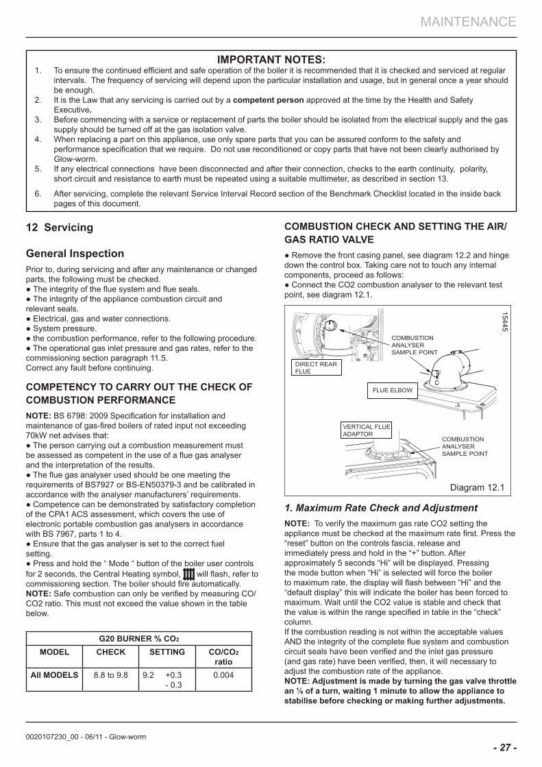
CoMbUSTIon CHeCK anD SeTTInG THe aIR/GaS RaTIo ValVe● Remove the front casing panel, see diagram 12.2 and hingedown the control box. Taking care not to touch any internalcomponents, proceed as follows:● Connect the CO2 combustion analyser to the relevant test point, see diagram 12.1.
1. Maximum Rate Check and AdjustmentnoTe: To verify the maximum gas rate CO2 setting the appliance must be checked at the maximum rate first. Press the “reset” button on the controls fascia, release andimmediately press and hold in the “+” button. After approximately 5 seconds “Hi” will be displayed. Pressing the mode button when “Hi” is selected will force the boiler to maximum rate, the display will flash between “Hi” and the “default display” this will indicate the boiler has been forced to maximum. Wait until the CO2 value is stable and check that the value is within the range specified in table in the “check” column. If the combustion reading is not within the acceptable valuesAND the integrity of the complete flue system and combustioncircuit seals have been verified and the inlet gas pressure(and gas rate) have been verified, then, it will necessary toadjust the combustion rate of the appliance.noTe: adjustment is made by turning the gas valve throttle an ⅛ of a turn, waiting 1 minute to allow the appliance to stabilise before checking or making further adjustments.
0020107230_00 - 06/11 - Glow-worm
MAINTENANCE
- 28 -
Diagram 12.2
14291
Before commencing with a service or replacement of parts.The boiler should be isolated from the electrical and gassupplies.
● Rotate the “throttle”(anti-clockwise to increase), to therequired CO2, refer to diagram 12.4 and the “SETTING” column in the table.● Exit the forced rate function, press the “mode” and “+”buttons simultaneously, this will reset the boiler to the defaultdisplay. Now proceed to check the minimum rate adjustment.
2. Minimum Rate Check and Adjustment● Now check the minimum gas rate CO2 setting: Press and release the “reset” button on the controls fascia, then immediately press and hold in either of the “+” buttons. After approximately 5 seconds “Hi” will be displayed. Pressing the “+” or “-” buttons will toggle between “Hi” and “Lo”. Press the mode button when “Lo” is selected, this will force the boiler to minimum rate and the display will flash “Lo”, indicating the boiler is operating at minimum.● Wait until the CO2 value is stable and check that the value is within the range specified in table in the “check” column.If adjustment is necessary, proceed as follows:noTe: adjustment of the Co2 at minimum rate is verycoarse and should not be adjusted more than an ⅛ of a turn at a time. Wait 1 minute to allow the appliance to stabilise before checking or making further adjustments.● Gradually rotate the “offset adjustment” (anti-clockwise todecrease) to the required CO2, refer to diagram 12.4 and the“SETTING” column in the table.● Exit the minimum rate function, press the “mode” and “+”buttons simultaneously, this will reset the boiler to the defaultdisplay.
3. Re-Check CO2 and check the CO/CO2 combustion ratio.● Re-check the maximum and minimum CO2 values to ensure that they are within the “setting” limits in the table then check the CO/CO2 combustion ratio does not exceed the value in the CO/CO2 column of the table. If the CO/CO2 ratio exceeds the value in the table, a complete servicing of the appliance will be necessary, refer to section 12.1. If the CO2 and the CO/CO2 ratio falls within the tolerances quoted, exit the function press the “mode” and “+” buttons simultaneously, this will reset the boiler to the default display.Remove the analyser probe and replace the cap on thesampling point, replace the controls fascia, inner and frontcasing panels.IMPoRTanT: Remember to replace the sample point cap on completion of the test.
GaS RaTe CHeCKCheck the gas rates as described in the commissioningsection.
CoMPleTIonIf it is not possible to achieve the required results for eitherthe combustion or gas rates, it will be necessary to completea full service of the appliance and then repeat the combustioncheck procedure. If after servicing and adjustment of the appliance the combustion values are still unacceptable and after further remedial work has been carried out, the appliance must be disconnected until the CO/CO2 ratio is acceptable. Advice can be sought from the Glow-worm Technical Helpline.
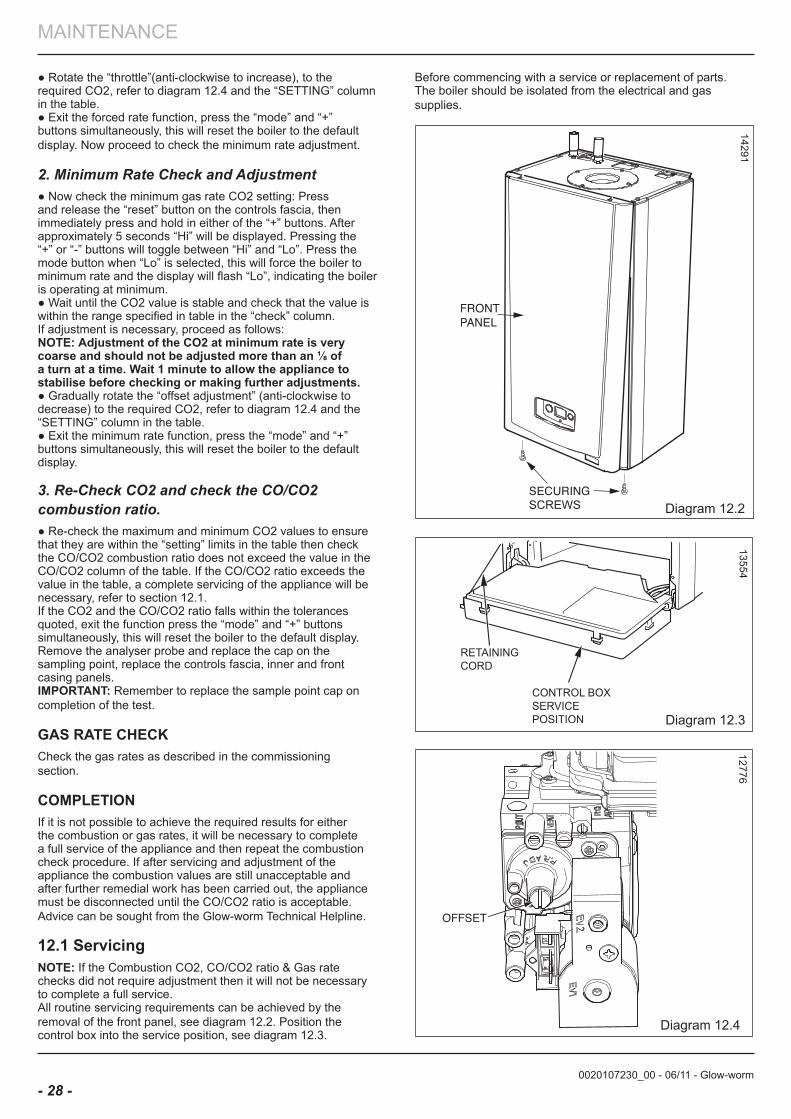
12.1 ServicingnoTe: If the Combustion CO2, CO/CO2 ratio & Gas rate checks did not require adjustment then it will not be necessary to complete a full service.All routine servicing requirements can be achieved by theremoval of the front panel, see diagram 12.2. Position the control box into the service position, see diagram 12.3.
13554
Diagram 12.3
Diagram 12.4
12776
0020107230_00 - 06/11 - Glow-worm
MAINTENANCE
- 29 -
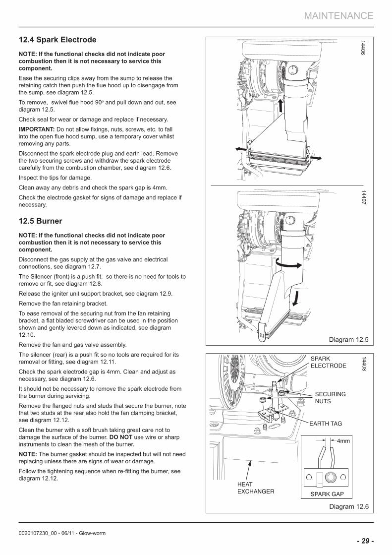
12.4 Spark electrodenoTe: If the functional checks did not indicate poor combustion then it is not necessary to service this component.Ease the securing clips away from the sump to release the retaining catch then push the flue hood up to disengage from the sump, see diagram 12.5.
To remove, swivel flue hood 90o and pull down and out, see diagram 12.5.
Check seal for wear or damage and replace if necessary.
IMPoRTanT: Do not allow fixings, nuts, screws, etc. to fall into the open flue hood sump, use a temporary cover whilst removing any parts.
Disconnect the spark electrode plug and earth lead. Remove the two securing screws and withdraw the spark electrode carefully from the combustion chamber, see diagram 12.6.
Inspect the tips for damage.
Clean away any debris and check the spark gap is 4mm.
Check the electrode gasket for signs of damage and replace if necessary.
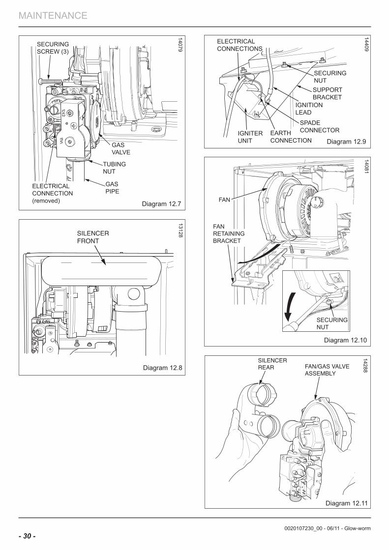
12.5 burnernoTe: If the functional checks did not indicate poor combustion then it is not necessary to service this component.Disconnect the gas supply at the gas valve and electrical connections, see diagram 12.7.
The Silencer (front) is a push fit, so there is no need for tools to remove or fit, see diagram 12.8.
Release the igniter unit support bracket, see diagram 12.9.
Remove the fan retaining bracket.
To ease removal of the securing nut from the fan retaining bracket, a flat bladed screwdriver can be used in the position shown and gently levered down as indicated, see diagram 12.10.
Remove the fan and gas valve assembly.
The silencer (rear) is a push fit so no tools are required for its removal or fitting, see diagram 12.11.
Check the spark electrode gap is 4mm. Clean and adjust as necessary, see diagram 12.6.
It should not be necessary to remove the spark electrode from the burner during servicing.
Remove the flanged nuts and studs that secure the burner, note that two studs at the rear also hold the fan clamping bracket, see diagram 12.12.
Clean the burner with a soft brush taking great care not to damage the surface of the burner. Do noT use wire or sharp instruments to clean the mesh of the burner.
noTe: The burner gasket should be inspected but will not need replacing unless there are signs of wear or damage.
Follow the tightening sequence when re-fitting the burner, see diagram 12.12.
1440614407
Diagram 12.5
Diagram 12.6
14408
0020107230_00 - 06/11 - Glow-worm
MAINTENANCE
- 30 -
GASVALVE
GASPIPE
ELECTRICALCONNECTION(removed)
SECURINGSCREW (3)
TUBINGNUT
Diagram 12.714079
Diagram 12.8
13128FAN
SECURING NUT
FAN RETAINING BRACKET
Diagram 12.11
14288
Diagram 12.10
14081
Diagram 12.9
14409
SECURING NUT SUPPORT BRACKET
IGNITION LEAD
SPADE CONNECTOR IGNITER
UNIT EARTH CONNECTION
ELECTRICAL CONNECTIONS
0020107230_00 - 06/11 - Glow-worm
MAINTENANCE
- 31 -
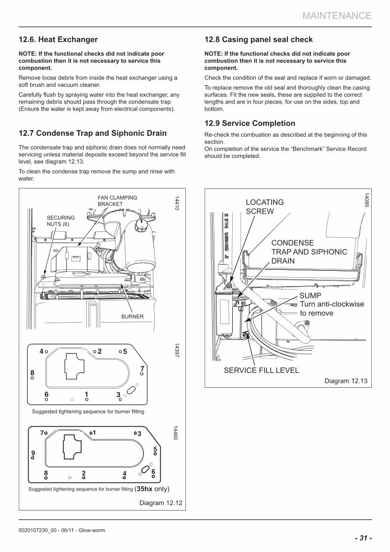
12.6. Heat exchangernoTe: If the functional checks did not indicate poor combustion then it is not necessary to service this component.Remove loose debris from inside the heat exchanger using a soft brush and vacuum cleaner.
Carefully flush by spraying water into the heat exchanger, any remaining debris should pass through the condensate trap (Ensure the water is kept away from electrical components).
12.7 Condense Trap and Siphonic DrainThe condensate trap and siphonic drain does not normally need servicing unless material deposits exceed beyond the service fill level, see diagram 12.13.
To clean the condense trap remove the sump and rinse with water.
Diagram 12.13
14089
SECURING NUTS (6)
BURNER
FAN CLAMPING BRACKET
Diagram 12.12
1441014397
12.8 Casing panel seal checknoTe: If the functional checks did not indicate poor combustion then it is not necessary to service this component.Check the condition of the seal and replace if worn or damaged.
To replace remove the old seal and thoroughly clean the casing surfaces. Fit the new seals, these are supplied to the correct lengths and are in four pieces, for use on the sides, top and bottom.
12.9 Service CompletionRe-check the combustion as described at the beginning of this section.On completion of the service the “Benchmark” Service Record should be completed.
14460
LOCATING SCREW
SERVICE FILL LEVEL
CONDENSETRAP AND SIPHONICDRAIN
SUMPTurn anti-clockwiseto remove
0020107230_00 - 06/11 - Glow-worm
MAINTENANCE
- 32 -
13 fault finding
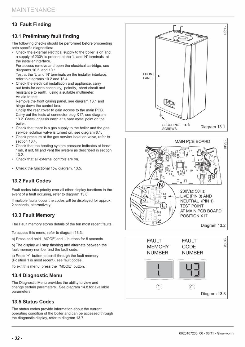
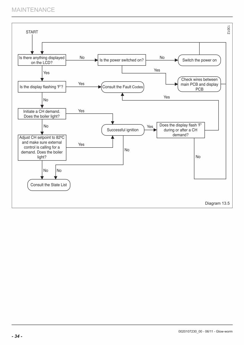
13.1 Preliminary fault findingThe following checks should be performed before proceeding onto specific diagnostics:• Check the external electrical supply to the boiler is on and a supply of 230V is present at the ‘L’ and ‘N’ terminals at the installer interface. For access remove and open the electrical cartridge, see diagrams 10.3. and 10.1. Test at the ‘L’ and ‘N’ terminals on the installer interface, refer to diagrams 10.2 and 13.4.• Check the electrical installation and appliance, carry out tests for earth continuity, polarity, short circuit and resistance to earth, using a suitable multimeter. An aid to test Remove the front casing panel, see diagram 13.1 and hinge down the control box. Unclip the rear cover to gain access to the main PCB. Carry out the tests at connector plug X17, see diagram 13.2. Check chassis earth at a bare metal point on the boiler.• Check that there is a gas supply to the boiler and the gas service isolation valve is turned on, see diagram 8.1. • Check pressure at the gas service isolation valve, refer to section 13.4.• Check that the heating system pressure indicates at least 1mb, if not, fill and vent the system as described in section 13.2.• Check that all external controls are on.
• Check the functional flow diagram, 13.5.
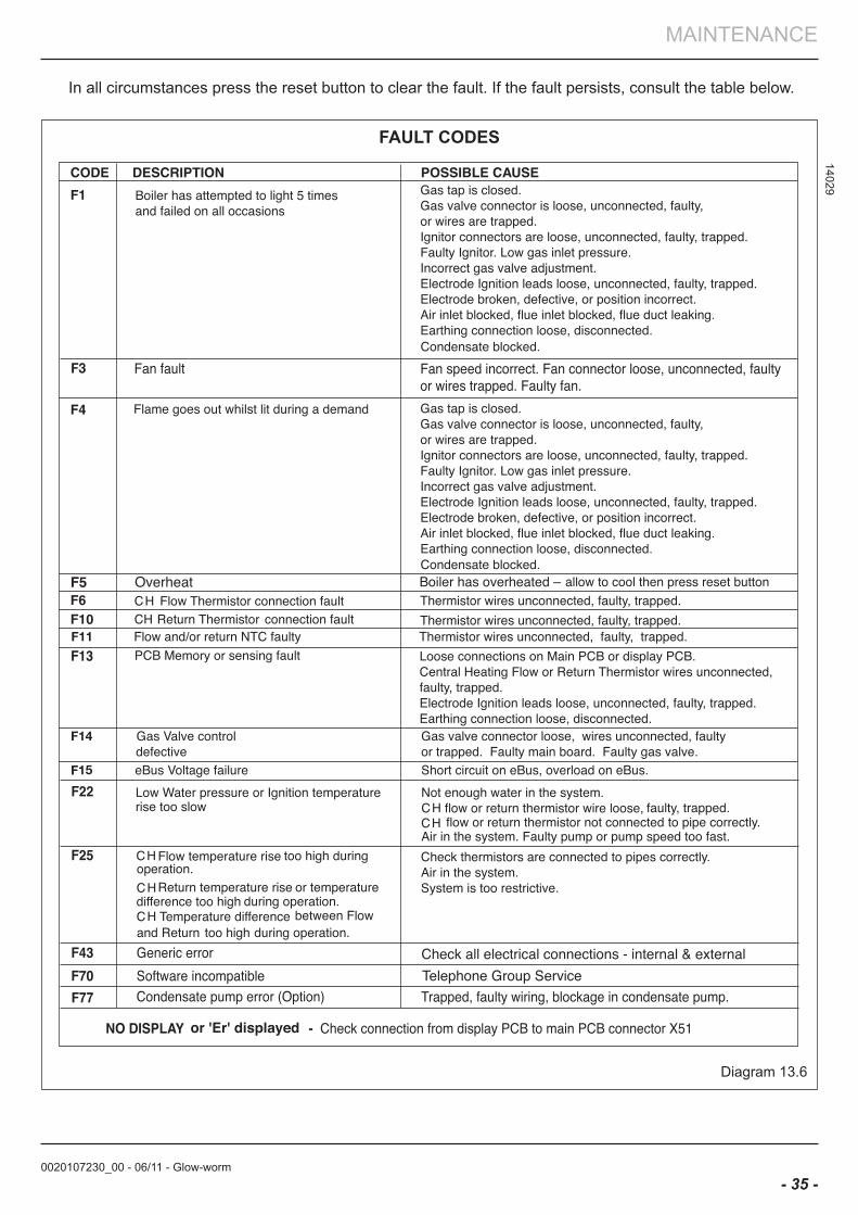
13.2 fault CodesFault codes take priority over all other display functions in the event of a fault occuring, refer to diagram 13.6.
If multiple faults occur the codes will be displayed for approx. 2 seconds, alternatively.
13.3 fault Memory The Fault memory stores details of the ten most recent faults.
To access this menu, refer to diagram 13.3:
a) Press and hold ‘MODE’ and ‘-’ buttons for 5 seconds.
b) The display will stop flashing and alternate between the fault memory number and the fault code.
c) Press ‘+’ button to scroll through the fault memory (Position 1 is most recent), see fault codes.
To exit this menu, press the ‘MODE’ button.
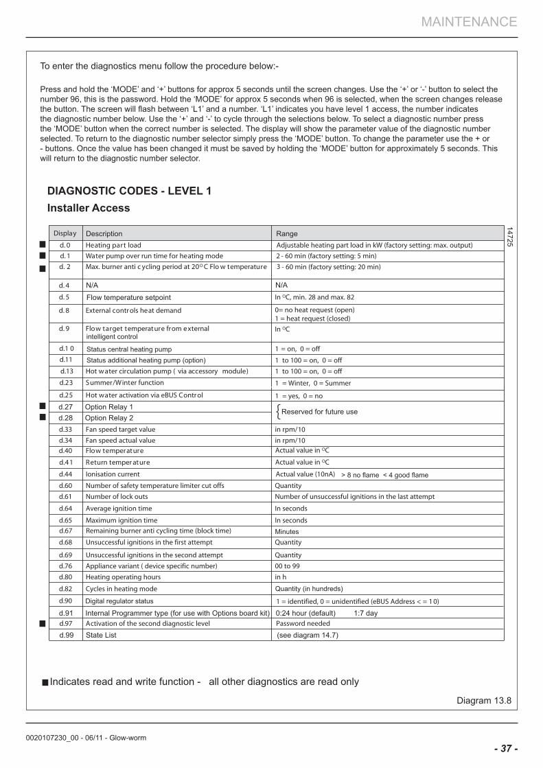
13.4 Diagnostic MenuThe Diagnostic Menu provides the ability to view and change certain parameters. See diagram 14.8 for available parameters.
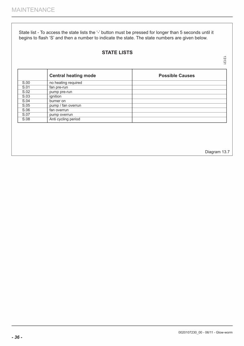
13.5 Status CodesThe status codes provide information about the current operating condition of the boiler and can be accessed through the diagnostic display, refer to diagram 13.7.
14028
Diagram 13.3
Diagram 13.2
1384514291
Diagram 13.1
0020107230_00 - 06/11 - Glow-worm
MAINTENANCE
- 33 -
13917
Diagram 13.4
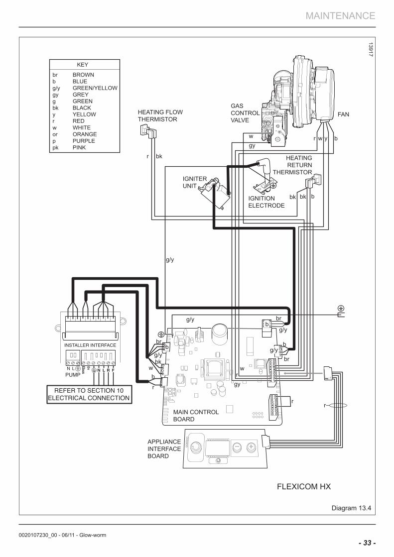
GASCONTROLVALVE
HEATING FLOWTHERMISTOR
HEATINGRETURN
THERMISTOR
FAN
IGNITIONELECTRODE
IGNITERUNIT
MAIN CONTROLBOARD
APPLIANCEINTERFACEBOARD
FLEXICOM HX
g/y
r bk
gyw
bk bk b
r w y b
brb
g/y
wbk
b
r
g/y br
g/yb
rr
br
b
gy
wr
g/y
br BROWNb BLUEg/y GREEN/YELLOW
g GREENgy GREY
bk BLACKy YELLOW
pk PINKp PURPLEor ORANGEw WHITEr RED
KEY
0020107230_00 - 06/11 - Glow-worm
MAINTENANCE
- 34 -
13012
Diagram 13.5
0020107230_00 - 06/11 - Glow-worm
MAINTENANCE
- 35 -
Diagram 13.6
14029
faUlT CoDeS
In all circumstances press the reset button to clear the fault. If the fault persists, consult the table below.
0020107230_00 - 06/11 - Glow-worm
MAINTENANCE
- 36 -
Diagram 13.7
13131
STaTe lISTS
State list - To access the state lists the ‘-’ button must be pressed for longer than 5 seconds until it begins to flash ‘S’ and then a number to indicate the state. The state numbers are given below.
0020107230_00 - 06/11 - Glow-worm
MAINTENANCE
- 37 -
DIaGnoSTIC CoDeS - leVel 1Installer access
14725
Diagram 13.8
d.99 State List (see diagram 14.7)
d.28 Option Relay 2 d.27 Option Relay 1
d.91 Internal Programmer type (for use with Options board kit) 0:24 hour (default) 1:7 day
N/A
Flow temperature setpoint
Description Range
intelligent control
Status additional heating pump (option)Status central heating pump
> 8 no flame < 4 good flame
Minutes
Digital regulator status
Quantity (in hundreds)
N/A
Reserved for future use
To enter the diagnostics menu follow the procedure below:-
Press and hold the ‘MODE’ and ‘+’ buttons for approx 5 seconds until the screen changes. Use the ‘+’ or ‘-’ button to select the number 96, this is the password. Hold the ‘MODE’ for approx 5 seconds when 96 is selected, when the screen changes release the button. The screen will flash between ‘L1’ and a number. ‘L1’ indicates you have level 1 access, the number indicates the diagnostic number below. Use the ‘+’ and ‘-’ to cycle through the selections below. To select a diagnostic number press the ‘MODE’ button when the correct number is selected. The display will show the parameter value of the diagnostic number selected. To return to the diagnostic number selector simply press the ‘MODE’ button. To change the parameter use the + or - buttons. Once the value has been changed it must be saved by holding the ‘MODE’ button for approximately 5 seconds. This will return to the diagnostic number selector.
Indicates read and write function - all other diagnostics are read only
0020107230_00 - 06/11 - Glow-worm
MAINTENANCE
- 38 -
Diagram 14.1
14 Replacement of Parts
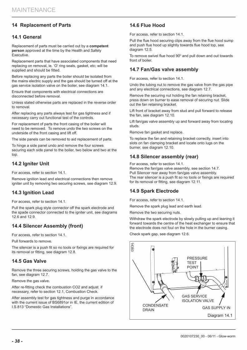
14.1 General Replacement of parts must be carried out by a competent person approved at the time by the Health and Safety Executive.
Replacement parts that have associated components that need replacing on removal, ie. ‘O’ ring seals, gasket, etc; will be supplied and should be fitted.
Before replacing any parts the boiler should be isolated from the mains electric supply and the gas should be turned off at the gas service isolation valve on the boiler, see diagram 14.1.
Ensure that components with electrical connections are disconnected before removal.
Unless stated otherwise parts are replaced in the reverse order to removal.
After replacing any parts always test for gas tightness and if necessary carry out functional test of the controls.
For replacement of parts the front casing of the boiler will need to be removed. To remove undo the two screws on the underside of the front casing and lift off.
The side panels can be removed to aid replacement of parts.
To hinge a side panel undo and remove the four screws securing each side panel to the boiler, two below and two at the top.
14.2 Igniter UnitFor access, refer to section 14.1.
Remove ignition lead and electrical connections then remove igniter unit by removing two securing screws, see diagram 12.9.
14.3 Ignition leadFor access, refer to section 14.1.
Pull the spark plug style connector off the spark electrode and the spade connector connected to the igniter unit, see diagrams 12.6 and 12.9.
14.4 Silencer assembly (front)For access, refer to section 14.1.
Pull forwards to remove.
The silencer is a push fit so no tools or fixings are required for its removal or fitting, see diagram 12.8.
14.5 Gas ValveRemove the three securing screws, holding the gas valve to the fan, see diagram 12.7.
Remove the gas valve.
After re-fitting check the combustion CO2 and adjust if necessary, refer to section 12.1, Combustion Check.
After assembly test for gas tightness and purge in accordance with the current issue of BS6891or in IE, the current edition of I.S.813 “Domestic Gas Installations”.
14383
14.6 flue HoodFor access, refer to section 14.1.
Pull the flue hood securing clips away from the flue hood sump and push flue hood up slightly towards flue hood top, see diagram 12.5.
To remove swivel flue hood 900 and pull down and out towards front of boiler.
14.7 fan/Gas valve assemblyFor access, refer to section 14.1.
Undo the tubing nut to remove the gas valve from the gas pipe and any electrical connections, see diagram 12.7.
Remove the securing nut holding the fan retaining bracket, press down on burner to ease removal of securing nut. Slide out the fan retaining bracket.
Lift front of bracket away from stud and pull forward to release the fan, see diagram 12.10.
Lift fan/gas valve assembly up and forward away from locating studs.
Remove fan gasket and replace.
To replace the fan and retaining bracket correctly, insert into slots on fan clamping bracket and locate onto lugs on the burner, see diagram 12.10.
14.8 Silencer assembly (rear)For access, refer to section 14.1.Remove the fan/gas valve assembly, see section 14.7.Pull Silencer rear away from fan/gas valve assembly. The rear silencer is a push fit so no tools or fixings are required for its removal or fitting, see diagram 12.11.
14.9 Spark electrodeFor access, refer to section 14.1.
Remove the spark plug lead and earth lead.
Remove the two securing nuts.
Withdraw the spark electrode by slowly pulling up and leaning it forward towards the centre of the heat exchanger to ensure that the electrode does not foul on the hole in the burner casing.
Check spark gap, see diagram 12.6.
PRESSURE TEST POINT
GAS SERVICE ISOLATION VALVE
GAS SUPPLY IN CONDENSATE DRAIN
0020107230_00 - 06/11 - Glow-worm
MAINTENANCE
- 39 -
14.10 burnerFor access, refer to section 14.1.
Remove igniter unit, flue hood, fan and gas valve assembly and spark electrode lead, refer to relevant sections.
Remove the flanged nuts and studs that secure the burner, note that two studs at the rear also hold the fan clamping bracket, see diagram 12.10.
noTe: The burner gasket should be inspected but will not need replacing unless there are signs of wear or damage.
IMPoRTanT: Do not allow fixings, nuts, screws, etc. to fall into the open flue hood sump, use a temporary cover whilst removing any parts.
14.11 Condensate TrapFor access, refer to section 14.1.Remove securing screw, see diagram 12.13.Disconnect the flexible condense drain pipe from the external plastic drain pipe beneath the boiler.Carefully pull the condensate trap down and forward so as not to spill its contents. The trap shoud be removed complete with the sealing grommet and flexible condensate drain pipe.
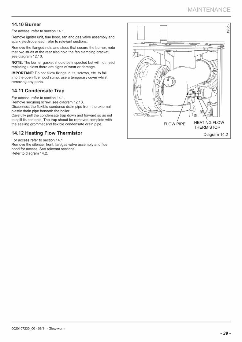
14.12 Heating flow ThermistorFor access refer to section 14.1Remove the silencer front, fan/gas valve assembly and flue hood for access. See relevant sections.Refer to diagram 14.2.
HEATING FLOWTHERMISTOR
FLOW PIPE
Diagram 14.2
12964
0020107230_00 - 06/11 - Glow-worm
MAINTENANCE
- 40 -
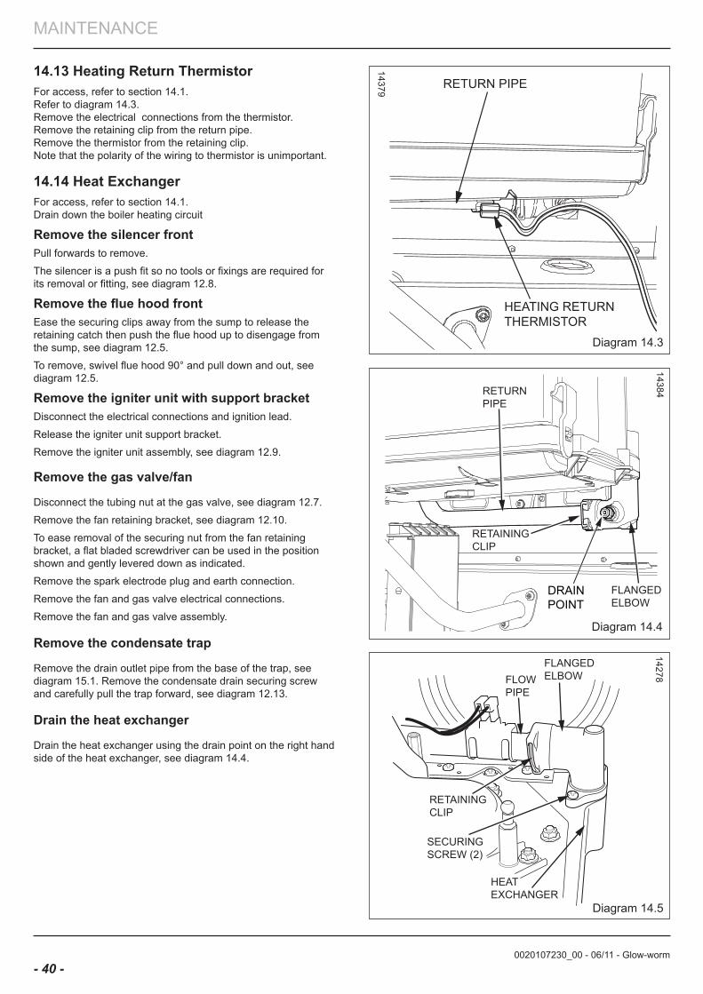
Diagram 14.3
14379
Diagram 14.4
14384
Diagram 14.5
14278
HEATING RETURN THERMISTOR
RETURN PIPE
DRAINPOINT
RETAININGCLIP
RETURNPIPE
FLANGEDELBOW
14.13 Heating Return ThermistorFor access, refer to section 14.1.Refer to diagram 14.3.Remove the electrical connections from the thermistor.Remove the retaining clip from the return pipe.Remove the thermistor from the retaining clip.Note that the polarity of the wiring to thermistor is unimportant.
14.14 Heat exchangerFor access, refer to section 14.1.Drain down the boiler heating circuit
Remove the silencer frontPull forwards to remove.
The silencer is a push fit so no tools or fixings are required for its removal or fitting, see diagram 12.8.
Remove the flue hood frontEase the securing clips away from the sump to release the retaining catch then push the flue hood up to disengage from the sump, see diagram 12.5.
To remove, swivel flue hood 90° and pull down and out, see diagram 12.5.
Remove the igniter unit with support bracket Disconnect the electrical connections and ignition lead.
Release the igniter unit support bracket.
Remove the igniter unit assembly, see diagram 12.9.
Remove the gas valve/fan
Disconnect the tubing nut at the gas valve, see diagram 12.7.
Remove the fan retaining bracket, see diagram 12.10.
To ease removal of the securing nut from the fan retaining bracket, a flat bladed screwdriver can be used in the position shown and gently levered down as indicated.
Remove the spark electrode plug and earth connection.
Remove the fan and gas valve electrical connections.
Remove the fan and gas valve assembly.
Remove the condensate trap
Remove the drain outlet pipe from the base of the trap, see diagram 15.1. Remove the condensate drain securing screw and carefully pull the trap forward, see diagram 12.13.
Drain the heat exchanger
Drain the heat exchanger using the drain point on the right hand side of the heat exchanger, see diagram 14.4.
0020107230_00 - 06/11 - Glow-worm
MAINTENANCE
- 41 -
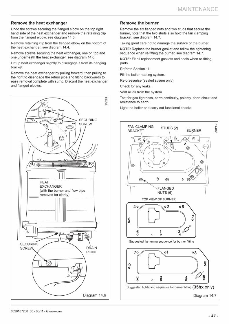
Diagram 14.6
14385
Diagram 14.7
14402
SECURINGSCREW
SECURING SCREW DRAIN
POINT
HEATEXCHANGER (with the burner and flow piperemoved for clarity)
Remove the heat exchangerUndo the screws securing the flanged elbow on the top right hand side of the heat exchanger and remove the retaining clip from the flanged elbow, see diagram 14 5.
Remove retaining clip from the flanged elbow on the bottom of the heat exchanger, see diagram 14.4.
Remove screws securing the heat exchanger, one on top and one underneath the heat exchanger, see diagram 14.6.
Lift up heat exchanger slightly to disengage it from its hanging bracket.
Remove the heat exchanger by pulling forward, then pulling to the right to disengage the return pipe and tilting backwards to ease removal complete with sump. Discard the heat exchanger and flanged elbows.
Remove the burner Remove the six flanged nuts and two studs that secure the burner, note that the two studs also hold the fan clamping bracket, see diagram 14.7.
Taking great care not to damage the surface of the burner.
noTe: Replace the burner gasket and follow the tightening sequence when re-fitting the burner, see diagram 14.7.
noTe: Fit all replacement gaskets and seals when re-fitting parts.
Refer to Section 11.
Fill the boiler heating system.
Re-pressurise (sealed sysem only)
Check for any leaks.
Vent all air from the system.
Test for gas tightness, earth continuity, polarity, short circuit and resistance to earth.
Light the boiler and carry out functional checks.
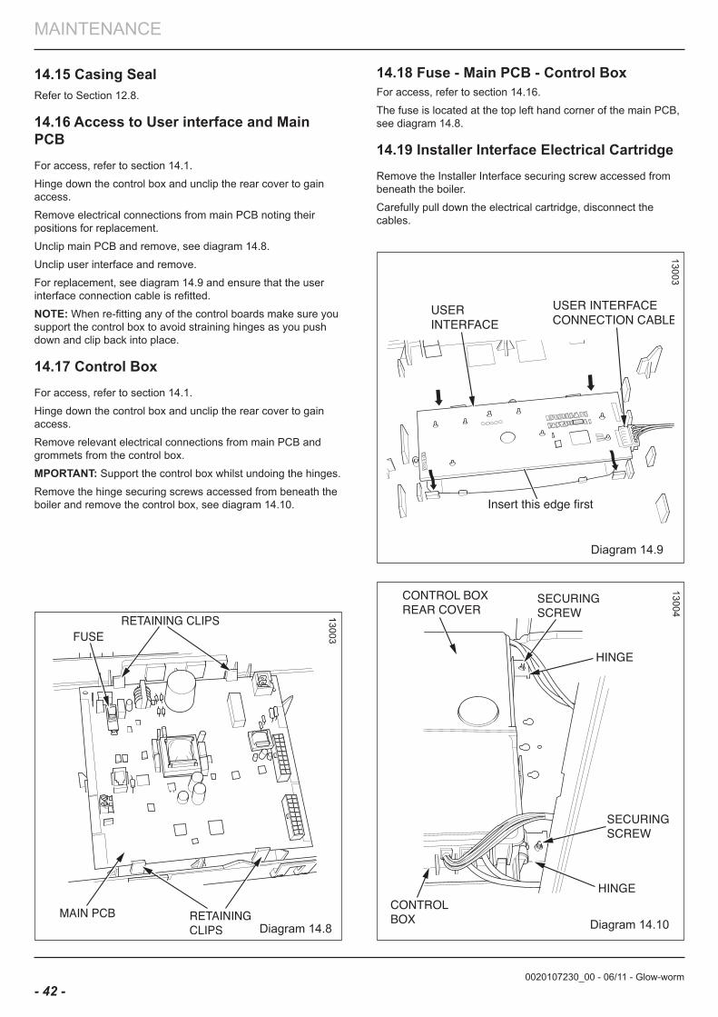
0020107230_00 - 06/11 - Glow-worm
MAINTENANCE
- 42 -
Diagram 14.8
13003
Diagram 14.9
13003
Diagram 14.10
13004
14.15 Casing SealRefer to Section 12.8.
14.16 access to User interface and Main PCbFor access, refer to section 14.1.
Hinge down the control box and unclip the rear cover to gain access.
Remove electrical connections from main PCB noting their positions for replacement.
Unclip main PCB and remove, see diagram 14.8.
Unclip user interface and remove.
For replacement, see diagram 14.9 and ensure that the user interface connection cable is refitted.
noTe: When re-fitting any of the control boards make sure you support the control box to avoid straining hinges as you push down and clip back into place.
14.17 Control boxFor access, refer to section 14.1.
Hinge down the control box and unclip the rear cover to gain access.
Remove relevant electrical connections from main PCB and grommets from the control box.
MPoRTanT: Support the control box whilst undoing the hinges.
Remove the hinge securing screws accessed from beneath the boiler and remove the control box, see diagram 14.10.
14.18 fuse - Main PCb - Control boxFor access, refer to section 14.16.
The fuse is located at the top left hand corner of the main PCB, see diagram 14.8.
14.19 Installer Interface electrical CartridgeRemove the Installer Interface securing screw accessed from beneath the boiler.
Carefully pull down the electrical cartridge, disconnect the cables.
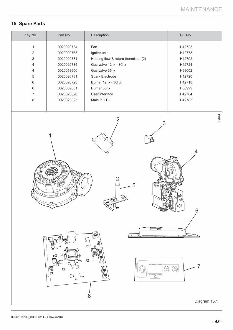
0020107230_00 - 06/11 - Glow-worm
MAINTENANCE
- 43 -
Diagram 15.1
13013
1
23
4
5
6
7
8
Key No. Part No. Description GC No
1 0020020734 Fan H42723
2 0020020763 Igniter unit H42773
3 0020020781 Heating flow & return thermistor (2) H42792
4 0020020735 Gas valve 12hx - 30hx H42724
4 0020059600 Gas valve 35hx H69002
5 0020020731 Spark Electrode H42720
6 0020020728 Burner 12hx - 30hx H42718
6 0020059601 Burner 35hx H68999
7 0020023826 User interface H42784
8 0020023825 Main P.C.B. H42783
15 Spare Parts
0020107230_00 - 06/11 - Glow-worm
MAINTENANCE
- 44 -
16 Manual handlingIMPoRTanT. With regards to the Manual Handling Opera-tions, 1992 Regulations, the following lift operation exceeds the recommended weight for a one man lift.General recommendations when handlingClear the route before attempting the lift.Ensure safe lifting techniques are used – keep back straight – bend us-ing legs. Keep load as close to body as possible. Do not twist – repo-sition feet instead. If 2 persons performing lift, ensure co-ordinated movements during lift. Avoid upper body/top heavy bending - do not lean forward/sideways. Recommend wear suitable cut resistant gloves with good grip to protect against sharp edges and ensure good grip.Always use assistance if required.
Removal of carton from delivery vanRecommend 2 person lift or 1 person with use of sack truck. If 1 person is performing lift, straddle the load, tilt and place carton into po-sition on truck. Recommend secure appliance onto truck with suitable straps. Ensure safe lifting techniques are used – keep back straight – bend using legs. Keep load as close to body as possible. If 2 persons performing lift, ensure co-ordinated movements during lift. Always use assistance if required.Carriage of carton from point of delivery to point of installation – ground floor.Recommend 2 person lift or 1 person with use of sack truck. If 1 person is performing lift, straddle the load, tilt and place carton into position on truck. Recommend secure appliance onto truck with suitable straps. Ensure safe lifting techniques are used – keep back straight – bend using legs. Keep load as close to body as possible. If 2 persons per-forming lift, ensure co-ordinated movements during lift. Clear the route before attempting the lift. If removing boiler from truck straddle the load and tilt forwards to facilitate secure grip. Ensure safe lifting techniques are used – keep back straight – bend using legs. Do not twist – repo-sition feet instead. Take care to avoid trip hazards, slippery or wet surfaces and when climbing steps and stairs. Always use assistance if required.Carriage of carton from point of delivery to point of installation – first or higher floor, cellar.Recommend 2-person lift or 1 person with use of sack truck. If 1 person is performing lift, straddle the load, tilt and place carton into position on truck. Recommend secure appliance onto truck with suitable straps. Ensure safe lifting techniques are used – keep back straight – bend us-ing legs. Keep load as close to body as possible. If 2 persons perform-ing lift, ensure co-ordinated movements during lift. Avoid upper body/top heavy bending - do not lean forward/sideways. Clear the route before attempting the lift. If removing boiler from truck straddle the load and tilt forwards to facilitate secure grip. Ensure safe lifting techniques are used – keep back straight – bend using legs. Do not twist – reposition feet instead. Take care to avoid trip hazards, slippery or wet surfaces and when climbing steps and stairs. Always use assistance if required.Carriage of carton from point of delivery to point of installation – roofspace.Recommend 2-person lift. Ensure co-ordinated movements during lift. Avoid upper body/top heavy bending - do not lean forward/side-ways. Clear the route before attempting the lift. Take care to avoid trip hazards, slippery or wet surfaces and when climbing steps and stairs. When transferring appliance into roofspace, recommend 1 person to be in roofspace to receive the appliance and other person to be below to pass up and support appliance. Ensure safe lifting techniques are used – keep back straight – bend using legs. Keep load as close to body as possible. Always use assistance if required. It is assumed safe access, flooring and adequate lighting are provided in the roof space. It is recommended a risk assessment of the roof space area be carried out before moving the appliance into the area to take into account access, stability of flooring, lighting and other factors, and appropriate measures taken.Unpacking of appliance from carton.Recommend 2 persons unpack appliance from carton. Always keep working area clear. Recommend cut base end of carton and open car-
ton flaps, then tilt boiler forwards from its side onto its base and remove carton by sliding up over the boiler. Ensure safe lifting techniques are used – keep back straight – bend using legs. Keep load as close to body as possible. Always use assistance if required. Dispose of pack-aging in a responsible manner. Recommend wear suitable cut resistant gloves with good grip to protect against sharp edges and ensure good grip when handling appliance outside packaging.Positioning of appliance for final Installation – no obstructions.This appliance is deemed to be a one person lift when removed from the carton. Fit bracket securely onto wall before lifting appliance into position. Obtain firm grip on front and sides of appliance, lift upwards, ensure stable balance achieved and lift upwards to position in place on bracket. Ensure safe lifting techniques are used – keep back straight – bend using legs - when lifting load from floor level. Do not twist – repo-sition feet instead. Keep boiler as close as possible to body throughout lift to minimise strain on back. Ensure co-ordinated movements to en-sure equal spread of weight of load. Always use assistance if required. Recommend wear suitable cut resistant gloves with good grip to protect against sharp edges and ensure good grip when handling appliance. Positioning of appliance for final Installation – above worktop, foreseeable obstructions etc.This appliance is deemed to be a one person lift when removed from the carton. Fit bracket securely onto wall before lifting appliance into posi-tion. Obtain firm grip on front and sides of appliance, lift upwards, onto worktop if practicable. Ensure stable balance achieved and lift upwards to position in place on bracket. If 2 persons positioning onto bracket obtain firm grip at front and sides/base of boiler. Ensure co-ordinated movements during 2 person lifts to ensure equal spread of weight of load. Ensure safe lifting techniques are used – keep back straight – bend using legs - when lifting load from floor level. Do not twist – reposition feet instead. Keep boiler as close as possible to body throughout lift to minimise strain on back. Avoid upper body/top heavy bending - do not lean forward/sideways. Always use assistance if required. Recommend wear suitable cut resistant gloves with good grip to protect against sharp edges and ensure good grip when handling appliance.Positioning of appliance for final Installation – within compartment etc. restricting installation.This appliance is deemed to be a one person lift when removed from the carton. Fit bracket securely onto wall before lifting appliance into posi-tion. Obtain firm grip on front and sides of appliance, lift upwards, onto worktop if practicable. Ensure stable balance achieved and lift upwards to drop into place onto bracket. If 2 persons positioning onto bracket obtain firm grip at front and sides/base of boiler. Ensure co-ordinated movements during 2 person lifts to ensure equal spread of weight of load. If 1 person positioning onto bracket recommend obtain firm grip supporting base of boiler. Ensure safe lifting techniques are used – keep back straight – bend using legs - when lifting load from floor level. Do not twist – reposition feet instead. Keep boiler as close as possible to body throughout lift to minimise strain on back. Always use assistance if required. Recommend wear suitable cut resistant gloves with good grip to protect against sharp edges and ensure good grip when handling appliance. Positioning of appliance for final Installation – in roof space restricting installation.This appliance is deemed to be a one person lift when removed from the carton. Obtain firm grip on front and sides of appliance, lift upwards, ensure stable balance achieved and lift upwards to drop into place onto bracket. If 2 persons positioning onto bracket obtain firm grip at front and sides/base of boiler. Ensure co-ordinated movements during 2 person lifts to ensure equal spread of weight of load. If 1 person positioning onto bracket recommend obtain firm grip supporting base of boiler. Ensure safe lifting techniques are used - keep back straight – bend using legs - when lifting load from floor level. Do not twist – reposition feet instead. Keep boiler as close as possible to body throughout lift to minimise strain on back. Always use assistance if required. Recommend wear suit-able cut resistant gloves with good grip to protect against sharp edges and ensure good grip when handling appliance. It is recommended a risk assessment of the roof space area be carried out before moving the appliance into the area to take into account access, stability of flooring, lighting and other factors, and appropriate measures taken.
0020107230_00 - 06/11 - Glow-worm
MAINTENANCE
- 45 -
15730
17 Declaration of conformity
SERVICE INTERVAL RECORDIt is recommended that your heating system is serviced regularly
and that you complete the appropriate Service Interval Record Below .
Service Provider. Before completing the appropriate Service Interval Record below, please ensure you have carried out the serviceas described in the boiler manufacturer’s instructions. Always use the manufacturer ‘s specified spare part when replacing all controls.
SERVICE 1 Date
Energy Effi ciency Checklist completed? Yes No
Engineer Name
Company Name
Telephone Number
Engineer ID Number
Comments Signature
SERVICE 3 Date
Energy Effi ciency Checklist completed? Yes No
Engineer Name
Company Name
Telephone Number
Engineer ID Number
Comments
Signature
SERVICE 5 Date
Energy Effi ciency Checklist completed? Yes No
Engineer Name
Company Name
Telephone Number
Engineer ID Number
Comments
Signature
SERVICE 7 Date
Energy Effi ciency Checklist completed? Yes No
Engineer Name
Company Name
Telephone Number
Engineer ID Number
Comments
Signature
SERVICE 9 Date
Energy Effi ciency Checklist completed? Yes No
Engineer Name
Company Name
Telephone Number
Engineer ID Number
Comments
Signature
SERVICE 2 Date
Energy Effi ciency Checklist completed? Yes No
Engineer Name
Company Name
Telephone Number
Engineer ID Number
Comments
Signature
SERVICE 4 Date
Energy Effi ciency Checklist completed? Yes No
Engineer Name
Company Name
Telephone Number
Engineer ID Number
Comments
Signature
SERVICE 6 Date
Energy Effi ciency Checklist completed? Yes No
Engineer Name
Company Name
Telephone Number
Engineer ID Number
Comments
Signature
SERVICE 8 Date
Energy Effi ciency Checklist completed? Yes No
Engineer Name
Company Name
Telephone Number
Engineer ID Number
Comments
Signature
SERVICE 10 Date
Energy Effi ciency Checklist completed? Yes No
Engineer Name
Company Name
Telephone Number
Engineer ID Number
Comments
Signature
GLOW-WORM
Nottingham Road, Belper, Derbyshire. DE56 1JT
Because of our constant endeavour for improvement, details may vary slightly from those shown in these instructions.
www.glow-worm.co.uk
Sub
ject
to e
ngin
eerin
g ch
ange
s00
2010
7230
_00
- 06/
11