Embed Size (px)
Citation preview

TECHNICALDATA
TECHNICAL DATA Unit : mm
ww
w.w
oojin
plai
mm
.com
WOOJIN PLAIMM constantly performs research & development for new product lines of machines in order to provide with the best solution to the clients.
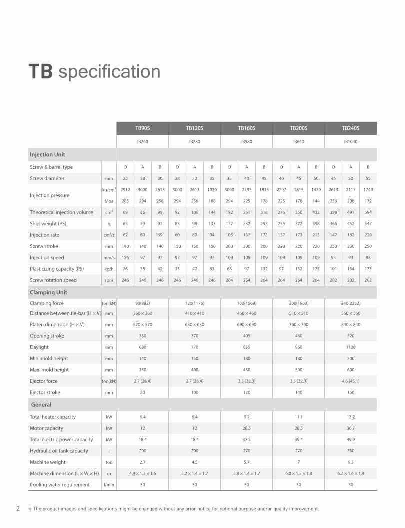
2 ※ The product images and specifications might be changed without any prior notice for optional purpose and/or quality improvement.
TB90S TB120S TB160S TB200S TB240S TB280S TB380S TB480S TB580S TB680S TB880S
IB260 IB280 IB580 IB640 IB1040 IB1320 IB2140 IB2610 IB3280 IB4670 IB6970
Injection Unit
Screw & barrel type O A B O A B O A B O A B O A B O A B O A B O A B O A B O A B O A B
Screw diameter mm 25 28 30 28 30 35 35 40 45 40 45 50 45 50 55 50 55 60 65 70 75 65 70 80 70 80 90 80 90 105 95 105 115
Injection pressurekg/cm² 2912 3000 2613 3000 2613 1920 3000 2297 1815 2297 1815 1470 2613 2117 1749 2394 1979 1663 2020 1741 1517 2020 1741 1333 1939 1484 1173 1877 1483 1090 1687 1381 1151
Mpa 285 294 256 294 256 188 294 225 178 225 178 144 256 208 172 235 194 163 198 171 149 198 171 131 190 146 115 184 145 107 165 135 113
Theoretical injection volume cm³ 69 86 99 92 106 144 192 251 318 276 350 432 398 491 594 550 665 792 1062 1231 1414 1294 1501 1960 1693 2212 2799 2488 3149 4286 4132 5048 6055
Shot weight (PS) g 63 79 91 85 98 133 177 232 293 255 322 398 366 452 547 507 613 730 978 1135 1303 1193 1383 1806 1560 2038 2579 2293 2902 3950 3808 4652 5580
Injection rate cm³/s 62 60 69 60 69 94 105 137 173 137 173 213 147 182 220 197 238 284 283 328 377 283 328 429 503 657 832 638 808 1099 898 1097 1316
Screw stroke mm 140 140 140 150 150 150 200 200 200 220 220 220 250 250 250 280 280 280 320 320 320 390 390 390 440 440 440 495 495 495 583 583 583
Injection speed mm/s 126 97 97 97 97 97 109 109 109 109 109 109 93 93 93 100 100 100 85 85 85 85 85 85 131 131 131 127 127 127 127 127 127
Plasticizing capacity (PS) kg/h 26 35 42 35 42 63 68 97 132 97 132 175 101 134 173 132 170 214 189 230 276 189 230 328 293 371 449 370 447 618 478 595 695
Screw rotation speed rpm 246 246 246 246 246 246 264 264 264 264 264 264 202 202 202 199 199 199 141 141 141 141 141 141 180 160 141 159 141 129 130 124 114
Clamping Unit
Clamping force ton(kN) 90(882) 120(1176) 160(1568) 200(1960) 240(2352) 280(2744) 380(3724) 480(4704) 580(5684) 680(6664) 880(8624)
Distance between tie-bar (H × V) mm 360 × 360 410 × 410 460 × 460 510 × 510 560 × 560 610 × 610 710 × 710 830 × 830 910 × 910 1020 × 1020 1110 × 1110
Platen dimension (H × V) mm 570 × 570 630 × 630 690 × 690 760 × 760 840 × 840 920 × 920 1065 × 1065 1220 × 1220 1340 × 1340 1500 × 1500 1630 × 1630
Opening stroke mm 330 370 405 460 520 570 700 780 850 950 1200
Daylight mm 680 770 855 960 1120 1220 1450 1580 1800 2050 2400
Min. mold height mm 140 150 180 180 200 250 300 350 400 450 500
Max. mold height mm 350 400 450 500 600 650 750 800 950 1100 1200
Ejector force ton(kN) 2.7 (26.4) 2.7 (26.4) 3.3 (32.3) 3.3 (32.3) 4.6 (45.1) 4.6 (45.1) 7 (68.6) 11 (107.8) 15.8 (154.8) 18.6 (182.2) 28.1 (275.3)
Ejector stroke mm 80 100 120 140 150 170 200 200 225 255 255
General
Total heater capacity kW 6.4 6.4 9.2 11.1 13.2 15.5 24.3 24.3 28.2 35.4 48.8
Motor capacity kW 12 12 28.3 28.3 36.7 43 56.3 56.3 93(36.7+56.3) 112.6(56.3+56.3) 142.3(56.3+43+43)
Total electric power capacity kW 18.4 18.4 37.5 39.4 49.9 58.5 80.6 80.6 121.2 148 191.1
Hydraulic oil tank capacity l 200 200 270 270 330 385 535 535 900 1100 1300
Machine weight ton 2.7 4.5 5.7 7 9.5 12.5 18 26 34 47 55
Machine dimension (L × W × H) m 4.9 × 1.3 × 1.6 5.2 × 1.4 × 1.7 5.8 × 1.4 × 1.7 6.0 × 1.5 × 1.8 6.7 × 1.6 × 1.9 7.3 × 1.7 × 2.0 8.2 × 1.8 × 2.1 9.1 × 2.1 × 2.2 10.6 × 2.4 × 2.3 11.7 × 2.6 × 2.4 13.3 × 2.8 × 2.7
Cooling water requirement l/min 30 30 30 30 30 30 60 60 60 60 80
TB specification
3
WOOJINPLAIMM
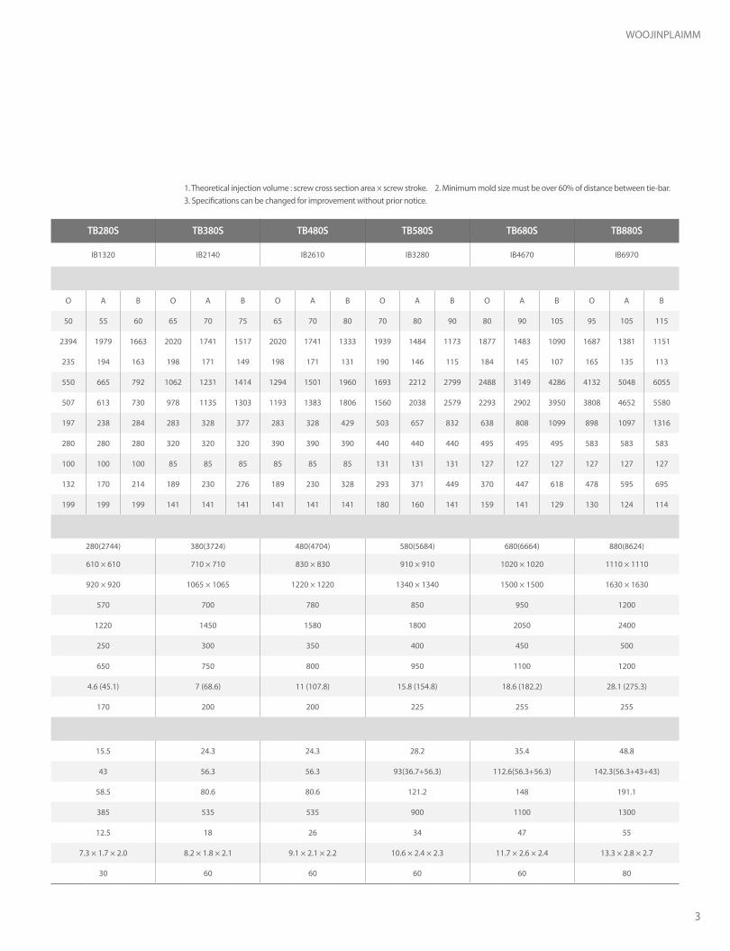
TB90S TB120S TB160S TB200S TB240S TB280S TB380S TB480S TB580S TB680S TB880S
IB260 IB280 IB580 IB640 IB1040 IB1320 IB2140 IB2610 IB3280 IB4670 IB6970
Injection Unit
Screw & barrel type O A B O A B O A B O A B O A B O A B O A B O A B O A B O A B O A B
Screw diameter mm 25 28 30 28 30 35 35 40 45 40 45 50 45 50 55 50 55 60 65 70 75 65 70 80 70 80 90 80 90 105 95 105 115
Injection pressurekg/cm² 2912 3000 2613 3000 2613 1920 3000 2297 1815 2297 1815 1470 2613 2117 1749 2394 1979 1663 2020 1741 1517 2020 1741 1333 1939 1484 1173 1877 1483 1090 1687 1381 1151
Mpa 285 294 256 294 256 188 294 225 178 225 178 144 256 208 172 235 194 163 198 171 149 198 171 131 190 146 115 184 145 107 165 135 113
Theoretical injection volume cm³ 69 86 99 92 106 144 192 251 318 276 350 432 398 491 594 550 665 792 1062 1231 1414 1294 1501 1960 1693 2212 2799 2488 3149 4286 4132 5048 6055
Shot weight (PS) g 63 79 91 85 98 133 177 232 293 255 322 398 366 452 547 507 613 730 978 1135 1303 1193 1383 1806 1560 2038 2579 2293 2902 3950 3808 4652 5580
Injection rate cm³/s 62 60 69 60 69 94 105 137 173 137 173 213 147 182 220 197 238 284 283 328 377 283 328 429 503 657 832 638 808 1099 898 1097 1316
Screw stroke mm 140 140 140 150 150 150 200 200 200 220 220 220 250 250 250 280 280 280 320 320 320 390 390 390 440 440 440 495 495 495 583 583 583
Injection speed mm/s 126 97 97 97 97 97 109 109 109 109 109 109 93 93 93 100 100 100 85 85 85 85 85 85 131 131 131 127 127 127 127 127 127
Plasticizing capacity (PS) kg/h 26 35 42 35 42 63 68 97 132 97 132 175 101 134 173 132 170 214 189 230 276 189 230 328 293 371 449 370 447 618 478 595 695
Screw rotation speed rpm 246 246 246 246 246 246 264 264 264 264 264 264 202 202 202 199 199 199 141 141 141 141 141 141 180 160 141 159 141 129 130 124 114
Clamping Unit
Clamping force ton(kN) 90(882) 120(1176) 160(1568) 200(1960) 240(2352) 280(2744) 380(3724) 480(4704) 580(5684) 680(6664) 880(8624)
Distance between tie-bar (H × V) mm 360 × 360 410 × 410 460 × 460 510 × 510 560 × 560 610 × 610 710 × 710 830 × 830 910 × 910 1020 × 1020 1110 × 1110
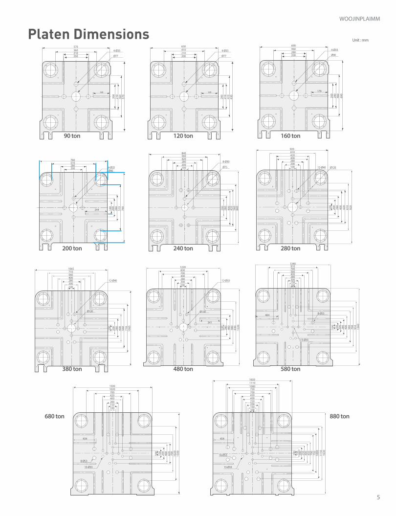
Platen dimension (H × V) mm 570 × 570 630 × 630 690 × 690 760 × 760 840 × 840 920 × 920 1065 × 1065 1220 × 1220 1340 × 1340 1500 × 1500 1630 × 1630
Opening stroke mm 330 370 405 460 520 570 700 780 850 950 1200
Daylight mm 680 770 855 960 1120 1220 1450 1580 1800 2050 2400
Min. mold height mm 140 150 180 180 200 250 300 350 400 450 500
Max. mold height mm 350 400 450 500 600 650 750 800 950 1100 1200
Ejector force ton(kN) 2.7 (26.4) 2.7 (26.4) 3.3 (32.3) 3.3 (32.3) 4.6 (45.1) 4.6 (45.1) 7 (68.6) 11 (107.8) 15.8 (154.8) 18.6 (182.2) 28.1 (275.3)
Ejector stroke mm 80 100 120 140 150 170 200 200 225 255 255
General
Total heater capacity kW 6.4 6.4 9.2 11.1 13.2 15.5 24.3 24.3 28.2 35.4 48.8
Motor capacity kW 12 12 28.3 28.3 36.7 43 56.3 56.3 93(36.7+56.3) 112.6(56.3+56.3) 142.3(56.3+43+43)
Total electric power capacity kW 18.4 18.4 37.5 39.4 49.9 58.5 80.6 80.6 121.2 148 191.1
Hydraulic oil tank capacity l 200 200 270 270 330 385 535 535 900 1100 1300
Machine weight ton 2.7 4.5 5.7 7 9.5 12.5 18 26 34 47 55
Machine dimension (L × W × H) m 4.9 × 1.3 × 1.6 5.2 × 1.4 × 1.7 5.8 × 1.4 × 1.7 6.0 × 1.5 × 1.8 6.7 × 1.6 × 1.9 7.3 × 1.7 × 2.0 8.2 × 1.8 × 2.1 9.1 × 2.1 × 2.2 10.6 × 2.4 × 2.3 11.7 × 2.6 × 2.4 13.3 × 2.8 × 2.7
Cooling water requirement l/min 30 30 30 30 30 30 60 60 60 60 80
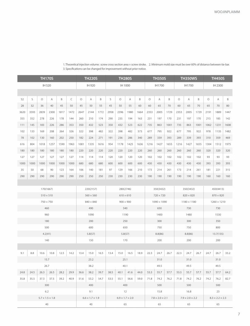
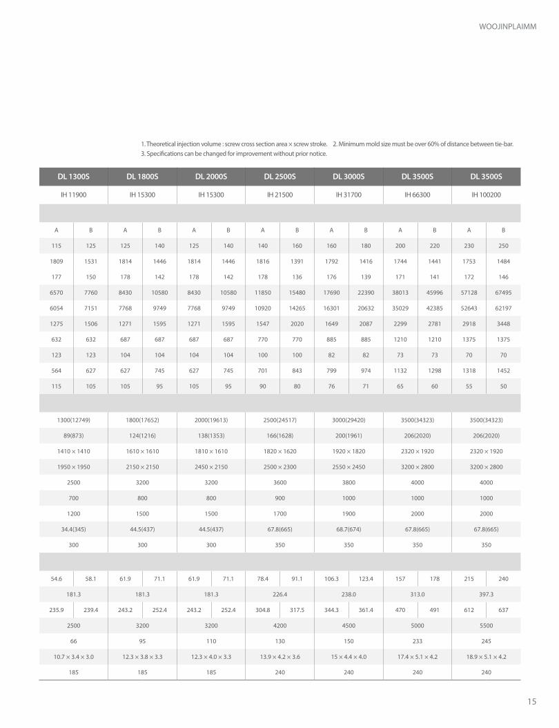
1. Theoretical injection volume : screw cross section area × screw stroke.3. Specifications can be changed for improvement without prior notice.
2. Minimum mold size must be over 60% of distance between tie-bar.

4
A B C D E F G H I J K
TB90S 4200 4860 860 1292 1190 1385 2170 1580 1480 646 646
TB120S 4425 5123 910 1342 1205 1400 2368 1630 1530 671 671
TB160S 4885 5709 950 1392 1225 1428 2624 1691 1585 706 686
TB200S 5025 5953 1000 1482 1275 1478 2873 1760 1665 751 731
TB240S 5640 6645 1084 1526 1348 1578 3285 1870 1778 773 753
TB280S 6135 7262 1170 1612 1360 1610 3612 1927 1825 816 796
TB380S 6895 8130 1340 1748 1375 1620 4255 2032 1920 884 864
TB480S 7790 9024 1440 2012 1373 1618 4739 2105 1993 1073 939
TB580S 9257 10532 1580 2332 1480 1650 5430 2213 2160 1239 1093
TB680S 10292 11680 1680 2511 1520 1710 6068 2315 2280 1329 1182
TB880S 11392 13234 1890 2751 1530 1745 7062 2623 2365 1448 1303
Unit : mm
Automatic extractor installation Hopper installment installation Nozzle dimension
A B C D E F G Ø H I Ø J L M N
TB90S 90 90 57 40 12 100 100 85 12 100 100 25 9
TB120S 105 105 47 40 12 100 100 85 12 100 100 30 9
TB160S 125 125 62 70 14 120 120 95 12 100 100 30 9
TB200S 150 150 62 70 14 120 120 95 12 100 50 30 12.5
TB240S 150 150 70 70 14 120 120 100 12 100 50 40 12.5
TB280S 150 150 68 70 14 120 120 100 12 100 50 40 12.5
TB380S 190 190 67 100 20 127 127 90 12 100 50 45 12.5
TB480S 210 210 67 100 20 127 127 68 12 100 50 40 19
TB580S 210 210 67 150 20 165 165 78 12 100 60 60 19
TB680S 280 280 84 230 20 165 165 88 12 100 60 60 19
TB880S 280 280 100 230 20 165 165 103 12 100 60 80 19
Unit : mm
※ The product images and specifications might be changed without any prior notice for optional purpose and/or quality improvement.
A B 4-M E Tap
C
D
A B 6-M E Tap
C
D
TB 90S ~ 480S
TB 580S ~ 880S
G
F
ØH 4-M I Tap
ØJ
R N
L M
E
G
C A
D
J K
B
FH
I
▼ Automatic extractor installation ▼ Hopper installment installation ▼ Nozzle dimension
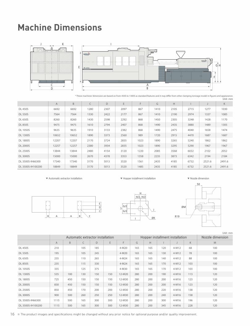
Machine Dimensions
5
WOOJINPLAIMM
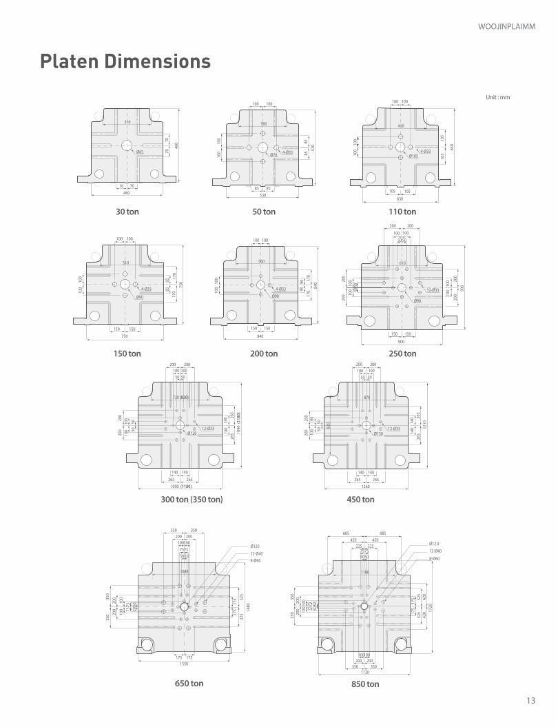
Unit : mmPlaten Dimensions
100
100
5704-Ø33
Ø77
360210200 200
200
210
410
630
210410630
570
360
210
200
4-Ø33
Ø77
690
8-Ø30
Ø75200280420560840
200100
280
420610920
200280510760
4-Ø33Ø90
200
280
510
760
244 140
200
280
420
560
840
400
200
280
420
610
920
400
12-Ø40 Ø120
12-Ø40
Ø120
200100
2804005607101065
200
100
280
400
560
710
1065
200
341
100
280400700830
1220
280
400
560
830
1220
12-Ø33
Ø130
200280400560700910
1340
150100
200
280
400
560
700
910
1340
150
100
4048-Ø53
13-Ø33
100
434
200
420
400
700
1020
1500
150
200
420400
70010201500
150100
13-Ø33
8-Ø53
454
200
400250
450700750
100011101630
150100
13-Ø33
16-Ø53
169
200280460690
200
280
460
4-Ø33
Ø90
179140
100
400
200
400
250
450
700
750
1000
1110
1630
150
100
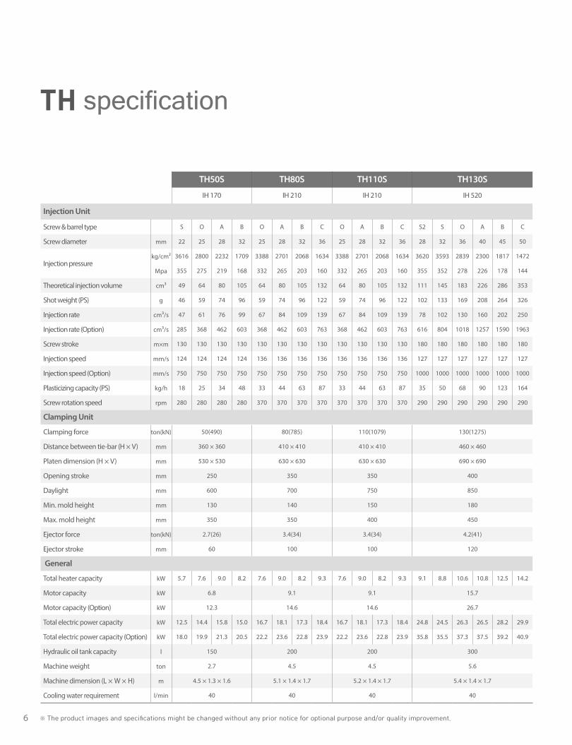
6 ※ The product images and specifications might be changed without any prior notice for optional purpose and/or quality improvement.
TH50S TH80S TH110S TH130S TH170S TH220S TH280S TH350S TH350WS TH450S
IH 170 IH 210 IH 210 IH 520 IH 520 IH 920 IH 1000 IH1700 IH1700 IH 2300
Injection Unit
Screw & barrel type S O A B O A B C O A B C S2 S O A B C S2 S O A B C O A B S O A B O A B O A B O A B
Screw diameter mm 22 25 28 32 25 28 32 36 25 28 32 36 28 32 36 40 45 50 28 32 36 40 45 50 45 50 55 45 50 55 60 60 65 70 60 65 70 65 70 80
Injection pressurekg/cm² 3616 2800 2232 1709 3388 2701 2068 1634 3388 2701 2068 1634 3620 3593 2839 2300 1817 1472 3620 3593 2839 2300 1817 1472 2647 2144 1772 2958 2396 1980 1664 2353 2005 1729 2353 2005 1729 2191 1889 1447
Mpa 355 275 219 168 332 265 203 160 332 265 203 160 355 352 278 226 178 144 355 352 278 226 178 144 260 210 174 290 235 194 163 231 197 170 231 197 170 215 185 142
Theoretical injection volume cm³ 49 64 80 105 64 80 105 132 64 80 105 132 111 145 183 226 286 353 111 145 183 226 286 353 350 432 523 350 432 523 622 735 863 1001 735 863 1001 1062 1231 1608
Shot weight (PS) g 46 59 74 96 59 74 96 122 59 74 96 122 102 133 169 208 264 326 102 133 169 208 264 326 322 398 482 322 398 482 573 677 795 922 677 795 922 978 1135 1482
Injection rate cm³/s 47 61 76 99 67 84 109 139 67 84 109 139 78 102 130 160 202 250 78 102 130 160 202 250 182 224 271 191 236 286 340 289 339 393 289 339 393 310 359 469
Injection rate (Option) cm³/s 285 368 462 603 368 462 603 763 368 462 603 763 616 804 1018 1257 1590 1963 616 804 1018 1257 1590 1963 1081 1335 1616 954 1178 1425 1636 1216 1427 1655 1216 1427 1655 1304 1512 1975
Screw stroke m×m 130 130 130 130 130 130 130 130 130 130 130 130 180 180 180 180 180 180 180 180 180 180 180 180 220 220 220 220 220 220 220 260 260 260 260 260 260 320 320 320
Injection speed mm/s 124 124 124 124 136 136 136 136 136 136 136 136 127 127 127 127 127 127 127 127 127 127 127 127 114 114 114 120 120 120 120 102 102 102 102 102 102 93 93 93
Injection speed (Option) mm/s 750 750 750 750 750 750 750 750 750 750 750 750 1000 1000 1000 1000 1000 1000 1000 1000 1000 1000 1000 1000 680 680 680 600 600 600 600 430 430 430 430 430 430 393 393 393
Plasticizing capacity (PS) kg/h 18 25 34 48 33 44 63 87 33 44 63 87 35 50 68 90 123 164 35 50 68 90 123 164 106 140 181 97 129 166 210 173 214 261 173 214 261 181 221 315
Screw rotation speed rpm 280 280 280 280 370 370 370 370 370 370 370 370 290 290 290 290 290 290 290 290 290 290 290 290 250 250 250 230 230 230 230 190 190 190 190 190 190 160 160 160
Clamping Unit
Clamping force ton(kN) 50(490) 80(785) 110(1079) 130(1275) 170(1667) 220(2157) 280(2746) 350(3432) 350(3432) 450(4413)
Distance between tie-bar (H × V) mm 360 × 360 410 × 410 410 × 410 460 × 460 510 × 510 560 × 560 610 × 610 720 × 720 820 × 820 870 × 820
Platen dimension (H × V) mm 530 × 530 630 × 630 630 × 630 690 × 690 750 × 750 840 × 840 900 × 900 1090 × 1090 1180 × 1180 1260 × 1210
Opening stroke mm 250 350 350 400 460 490 540 650 730 730
Daylight mm 600 700 750 850 960 1090 1190 1400 1480 1530
Min. mold height mm 130 140 150 180 180 200 250 300 300 350
Max. mold height mm 350 350 400 450 500 600 650 750 750 800
Ejector force ton(kN) 2.7(26) 3.4(34) 3.4(34) 4.2(41) 4.2(41) 5.8(57) 5.8(57) 8.8(86) 8.8(86) 13.7(135)
Ejector stroke mm 60 100 100 120 140 150 170 200 200 200
General
Total heater capacity kW 5.7 7.6 9.0 8.2 7.6 9.0 8.2 9.3 7.6 9.0 8.2 9.3 9.1 8.8 10.6 10.8 12.5 14.2 9.1 8.8 10.6 10.8 12.5 14.2 13.4 15.0 16.5 13.4 15.0 16.5 18.9 22.3 24.7 26.7 22.3 24.7 26.7 24.7 26.7 33.2
Motor capacity kW 6.8 9.1 9.1 15.7 15.7 23.2 25.1 31.0 31.0 31.0
Motor capacity (Option) kW 12.3 14.6 14.6 26.7 26.7 38.2 40.1 49.5 49.5 49.5
Total electric power capacity kW 12.5 14.4 15.8 15.0 16.7 18.1 17.3 18.4 16.7 18.1 17.3 18.4 24.8 24.5 26.3 26.5 28.2 29.9 24.8 24.5 26.3 26.5 28.2 29.9 36.6 38.2 39.7 38.5 40.1 41.6 44.0 53.3 55.7 57.7 53.3 55.7 57.7 55.7 57.7 64.2
Total electric power capacity (Option) kW 18.0 19.9 21.3 20.5 22.2 23.6 22.8 23.9 22.2 23.6 22.8 23.9 35.8 35.5 37.3 37.5 39.2 40.9 35.8 35.5 37.3 37.5 39.2 40.9 51.6 53.2 54.7 53.5 55.1 56.6 59.0 71.8 74.2 76.2 71.8 74.2 76.2 74.2 76.2 82.7
Hydraulic oil tank capacity l 150 200 200 300 300 400 400 500 500 500
Machine weight ton 2.7 4.5 4.5 5.6 6.2 9.1 12 15.8 16.8 23
Machine dimension (L × W × H) m 4.5 × 1.3 × 1.6 5.1 × 1.4 × 1.7 5.2 × 1.4 × 1.7 5.4 × 1.4 × 1.7 5.7 × 1.5 × 1.8 6.6 × 1.7 × 1.9 6.9 × 1.7 × 2.0 7.8 × 2.0 × 2.1 7.9 × 2.0 × 2.2 8.3 × 2.2 × 2.3
Cooling water requirement l/min 40 40 40 40 40 40 65 65 65 65
TH specification
7
WOOJINPLAIMM
TH50S TH80S TH110S TH130S TH170S TH220S TH280S TH350S TH350WS TH450S
IH 170 IH 210 IH 210 IH 520 IH 520 IH 920 IH 1000 IH1700 IH1700 IH 2300
Injection Unit
Screw & barrel type S O A B O A B C O A B C S2 S O A B C S2 S O A B C O A B S O A B O A B O A B O A B
Screw diameter mm 22 25 28 32 25 28 32 36 25 28 32 36 28 32 36 40 45 50 28 32 36 40 45 50 45 50 55 45 50 55 60 60 65 70 60 65 70 65 70 80
Injection pressurekg/cm² 3616 2800 2232 1709 3388 2701 2068 1634 3388 2701 2068 1634 3620 3593 2839 2300 1817 1472 3620 3593 2839 2300 1817 1472 2647 2144 1772 2958 2396 1980 1664 2353 2005 1729 2353 2005 1729 2191 1889 1447
Mpa 355 275 219 168 332 265 203 160 332 265 203 160 355 352 278 226 178 144 355 352 278 226 178 144 260 210 174 290 235 194 163 231 197 170 231 197 170 215 185 142
Theoretical injection volume cm³ 49 64 80 105 64 80 105 132 64 80 105 132 111 145 183 226 286 353 111 145 183 226 286 353 350 432 523 350 432 523 622 735 863 1001 735 863 1001 1062 1231 1608
Shot weight (PS) g 46 59 74 96 59 74 96 122 59 74 96 122 102 133 169 208 264 326 102 133 169 208 264 326 322 398 482 322 398 482 573 677 795 922 677 795 922 978 1135 1482
Injection rate cm³/s 47 61 76 99 67 84 109 139 67 84 109 139 78 102 130 160 202 250 78 102 130 160 202 250 182 224 271 191 236 286 340 289 339 393 289 339 393 310 359 469
Injection rate (Option) cm³/s 285 368 462 603 368 462 603 763 368 462 603 763 616 804 1018 1257 1590 1963 616 804 1018 1257 1590 1963 1081 1335 1616 954 1178 1425 1636 1216 1427 1655 1216 1427 1655 1304 1512 1975
Screw stroke m×m 130 130 130 130 130 130 130 130 130 130 130 130 180 180 180 180 180 180 180 180 180 180 180 180 220 220 220 220 220 220 220 260 260 260 260 260 260 320 320 320
Injection speed mm/s 124 124 124 124 136 136 136 136 136 136 136 136 127 127 127 127 127 127 127 127 127 127 127 127 114 114 114 120 120 120 120 102 102 102 102 102 102 93 93 93
Injection speed (Option) mm/s 750 750 750 750 750 750 750 750 750 750 750 750 1000 1000 1000 1000 1000 1000 1000 1000 1000 1000 1000 1000 680 680 680 600 600 600 600 430 430 430 430 430 430 393 393 393
Plasticizing capacity (PS) kg/h 18 25 34 48 33 44 63 87 33 44 63 87 35 50 68 90 123 164 35 50 68 90 123 164 106 140 181 97 129 166 210 173 214 261 173 214 261 181 221 315
Screw rotation speed rpm 280 280 280 280 370 370 370 370 370 370 370 370 290 290 290 290 290 290 290 290 290 290 290 290 250 250 250 230 230 230 230 190 190 190 190 190 190 160 160 160
Clamping Unit
Clamping force ton(kN) 50(490) 80(785) 110(1079) 130(1275) 170(1667) 220(2157) 280(2746) 350(3432) 350(3432) 450(4413)
Distance between tie-bar (H × V) mm 360 × 360 410 × 410 410 × 410 460 × 460 510 × 510 560 × 560 610 × 610 720 × 720 820 × 820 870 × 820
Platen dimension (H × V) mm 530 × 530 630 × 630 630 × 630 690 × 690 750 × 750 840 × 840 900 × 900 1090 × 1090 1180 × 1180 1260 × 1210
Opening stroke mm 250 350 350 400 460 490 540 650 730 730
Daylight mm 600 700 750 850 960 1090 1190 1400 1480 1530
Min. mold height mm 130 140 150 180 180 200 250 300 300 350
Max. mold height mm 350 350 400 450 500 600 650 750 750 800
Ejector force ton(kN) 2.7(26) 3.4(34) 3.4(34) 4.2(41) 4.2(41) 5.8(57) 5.8(57) 8.8(86) 8.8(86) 13.7(135)
Ejector stroke mm 60 100 100 120 140 150 170 200 200 200
General
Total heater capacity kW 5.7 7.6 9.0 8.2 7.6 9.0 8.2 9.3 7.6 9.0 8.2 9.3 9.1 8.8 10.6 10.8 12.5 14.2 9.1 8.8 10.6 10.8 12.5 14.2 13.4 15.0 16.5 13.4 15.0 16.5 18.9 22.3 24.7 26.7 22.3 24.7 26.7 24.7 26.7 33.2
Motor capacity kW 6.8 9.1 9.1 15.7 15.7 23.2 25.1 31.0 31.0 31.0
Motor capacity (Option) kW 12.3 14.6 14.6 26.7 26.7 38.2 40.1 49.5 49.5 49.5
Total electric power capacity kW 12.5 14.4 15.8 15.0 16.7 18.1 17.3 18.4 16.7 18.1 17.3 18.4 24.8 24.5 26.3 26.5 28.2 29.9 24.8 24.5 26.3 26.5 28.2 29.9 36.6 38.2 39.7 38.5 40.1 41.6 44.0 53.3 55.7 57.7 53.3 55.7 57.7 55.7 57.7 64.2
Total electric power capacity (Option) kW 18.0 19.9 21.3 20.5 22.2 23.6 22.8 23.9 22.2 23.6 22.8 23.9 35.8 35.5 37.3 37.5 39.2 40.9 35.8 35.5 37.3 37.5 39.2 40.9 51.6 53.2 54.7 53.5 55.1 56.6 59.0 71.8 74.2 76.2 71.8 74.2 76.2 74.2 76.2 82.7
Hydraulic oil tank capacity l 150 200 200 300 300 400 400 500 500 500
Machine weight ton 2.7 4.5 4.5 5.6 6.2 9.1 12 15.8 16.8 23
Machine dimension (L × W × H) m 4.5 × 1.3 × 1.6 5.1 × 1.4 × 1.7 5.2 × 1.4 × 1.7 5.4 × 1.4 × 1.7 5.7 × 1.5 × 1.8 6.6 × 1.7 × 1.9 6.9 × 1.7 × 2.0 7.8 × 2.0 × 2.1 7.9 × 2.0 × 2.2 8.3 × 2.2 × 2.3
Cooling water requirement l/min 40 40 40 40 40 40 65 65 65 65
1. Theoretical injection volume : screw cross section area × screw stroke.3. Specifications can be changed for improvement without prior notice.
2. Minimum mold size must be over 60% of distance between tie-bar.
8
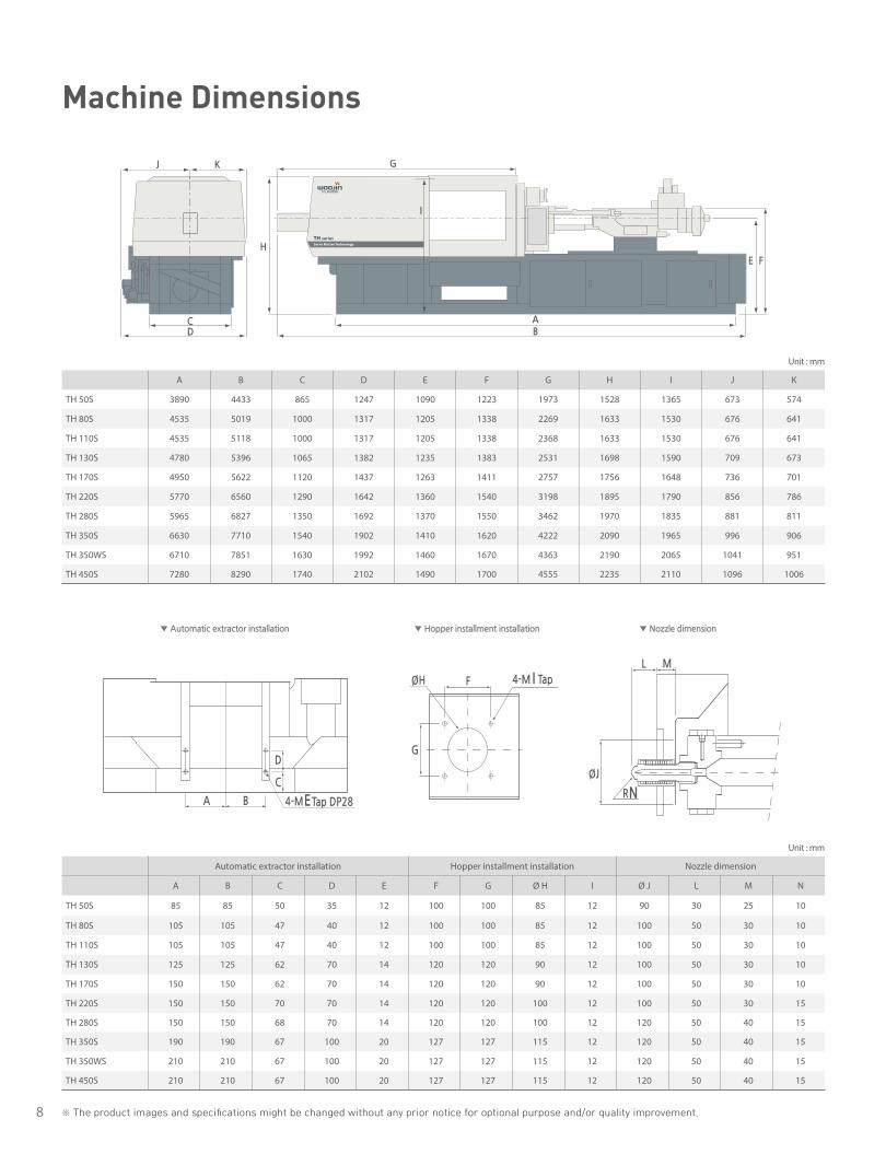
A B C D E F G H I J K
TH 50S 3890 4433 865 1247 1090 1223 1973 1528 1365 673 574
TH 80S 4535 5019 1000 1317 1205 1338 2269 1633 1530 676 641
TH 110S 4535 5118 1000 1317 1205 1338 2368 1633 1530 676 641
TH 130S 4780 5396 1065 1382 1235 1383 2531 1698 1590 709 673
TH 170S 4950 5622 1120 1437 1263 1411 2757 1756 1648 736 701
TH 220S 5770 6560 1290 1642 1360 1540 3198 1895 1790 856 786
TH 280S 5965 6827 1350 1692 1370 1550 3462 1970 1835 881 811
TH 350S 6630 7710 1540 1902 1410 1620 4222 2090 1965 996 906
TH 350WS 6710 7851 1630 1992 1460 1670 4363 2190 2065 1041 951
TH 450S 7280 8290 1740 2102 1490 1700 4555 2235 2110 1096 1006
Unit : mm
Unit : mm
Automatic extractor installation Hopper installment installation Nozzle dimension
A B C D E F G Ø H I Ø J L M N
TH 50S 85 85 50 35 12 100 100 85 12 90 30 25 10
TH 80S 105 105 47 40 12 100 100 85 12 100 50 30 10
TH 110S 105 105 47 40 12 100 100 85 12 100 50 30 10
TH 130S 125 125 62 70 14 120 120 90 12 100 50 30 10
TH 170S 150 150 62 70 14 120 120 90 12 100 50 30 10
TH 220S 150 150 70 70 14 120 120 100 12 100 50 30 15
TH 280S 150 150 68 70 14 120 120 100 12 120 50 40 15
TH 350S 190 190 67 100 20 127 127 115 12 120 50 40 15
TH 350WS 210 210 67 100 20 127 127 115 12 120 50 40 15
TH 450S 210 210 67 100 20 127 127 115 12 120 50 40 15
※ The product images and specifications might be changed without any prior notice for optional purpose and/or quality improvement.
DC
J
I
K
H
E F
AB
G
A B
C
D
4-M E Tap DP28
R N
L M
G
FØH 4-M I Tap
ØJ
A B
C
D
4-M E Tap DP28
R N
L M
G
FØH 4-M I Tap
ØJ
Machine Dimensions
▼ Automatic extractor installation ▼ Hopper installment installation ▼ Nozzle dimension

9
WOOJINPLAIMM
Platen Dimensions
12
51
25
125 125
10
01
00
100100100
150
750
10
0
150
100
10
0
17
085 7
50
69
0
17
0
85
150 150
840
90
90 1
70
17
0
100 100
10
01
00 8
40
10
01
00
20
0
50
5050
50
10
01
00
20
02
00
150 150
9009
00
12
10
100 100
200 200
20
0
14
0 26
5
14
0
26
5
140 140
265 265
50 50
100 100
200 200
50
50
10
01
0020
02
00
14
0 26
5
14
0
26
5
140 140
265 265
50 50
100 100
200 200
50
50
10
01
00
20
02
00
560
870
820
720 (820)
610
510460
12601090 (1180)
10
90
690
85
53
0
85
85
530
85
100100
100
100
360
(118
0)
Ø70 4-Ø33
Ø90
Ø120
4-Ø33
Ø90
4-Ø33
12-Ø30
Ø90
4-Ø40
12-Ø33 12-Ø33Ø120 Ø130
10
5
10
01
00
410
Ø90 4-Ø33 10
5
105105
100 100
63
0
630
10 ※ The product images and specifications might be changed without any prior notice for optional purpose and/or quality improvement.
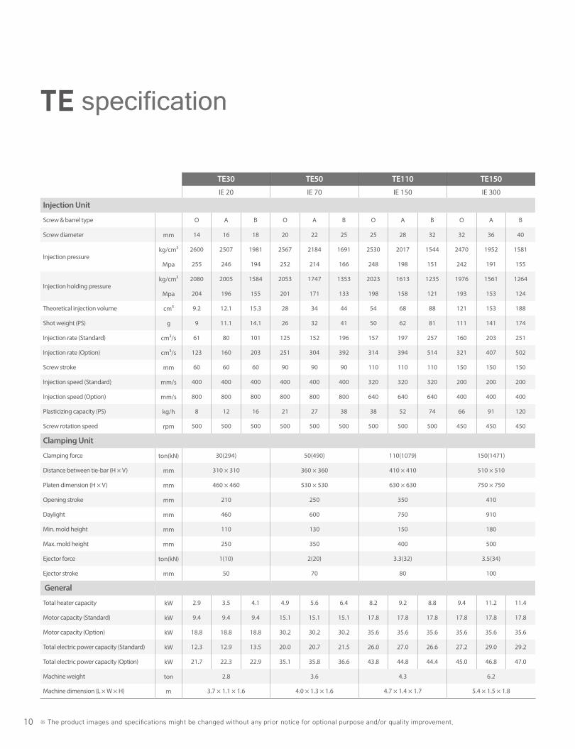
TE specification
TE30 TE50 TE110 TE150 TE200 TE250 TE300 TE350 TE450 TE650 TE850IE 20 IE 70 IE 150 IE 300 IE 400 IE 780 IE 1000 IE 1500 IE 2300 IE 7800 IE 7800
Injection Unit
Screw & barrel type O A B O A B O A B O A B O A B O A B O A B O A B O A B O O A
Screw diameter mm 14 16 18 20 22 25 25 28 32 32 36 40 36 40 45 45 50 55 50 55 60 60 65 70 65 70 80 95 95 105
Injection pressurekg/cm² 2600 2507 1981 2567 2184 1691 2530 2017 1544 2470 1952 1581 2440 1976 1561 2534 2052 1696 2558 2114 1776 2448 2086 1798 2307 1989 1523 2450 2450 2006
Mpa 255 246 194 252 214 166 248 198 151 242 191 155 239 194 153 249 201 166 251 207 174 240 205 176 226 195 149 240 240 197
Injection holding pressurekg/cm² 2080 2005 1584 2053 1747 1353 2023 1613 1235 1976 1561 1264 1951 1580 1249 2027 1642 1357 2046 1691 1421 1958 1669 1438 1846 1591 1218 1960 1960 1605
Mpa 204 196 155 201 171 133 198 158 121 193 153 124 191 155 122 199 161 133 201 166 139 192 164 141 181 156 119 192 192 157
Theoretical injection volume cm³ 9.2 12.1 15.3 28 34 44 54 68 88 121 153 188 163 201 254 318 393 475 432 522 622 735 862 1000 995 1325 1507 3544 3544 4330
Shot weight (PS) g 9 11.1 14.1 26 32 41 50 62 81 111 141 174 150 185 234 293 362 438 398 481 573 677 795 922 917 1063 1389 3225 3225 3940
Injection rate (Standard) cm³/s 61 80 101 125 152 196 157 197 257 160 203 251 162 201 254 239 295 356 295 356 424 424 498 577 498 577 754 1063 1063 1299
Injection rate (Option) cm³/s 123 160 203 251 304 392 314 394 514 321 407 502 325 402 508 477 589 713 589 713 848 848 996 1154
Screw stroke mm 60 60 60 90 90 90 110 110 110 150 150 150 160 160 160 200 200 200 220 220 220 260 260 260 300 300 300 500 500 500
Injection speed (Standard) mm/s 400 400 400 400 400 400 320 320 320 200 200 200 160 160 160 150 150 150 150 150 150 150 150 150 150 150 150 150 150 150
Injection speed (Option) mm/s 800 800 800 800 800 800 640 640 640 400 400 400 320 320 320 300 300 300 300 300 300 300 300 300
Plasticizing capacity (PS) kg/h 8 12 16 21 27 38 38 52 74 66 91 120 81 107 146 137 182 234 151 195 246 212 262 319 219 267 381 370 370 495
Screw rotation speed rpm 500 500 500 500 500 500 500 500 500 450 450 450 400 400 400 300 300 300 250 250 250 215 215 215 180 180 180 138 138 138
Clamping Unit
Clamping force ton(kN) 30(294) 50(490) 110(1079) 150(1471) 200(1961) 250(2452) 300(2942) 350(3432) 450(4413) 650(6374) 850(8336)
Distance between tie-bar (H × V) mm 310 × 310 360 × 360 410 × 410 510 × 510 560 × 560 610 × 610 720 × 720 820 × 820 870 × 820 1080 × 1080 1180 × 1180
Platen dimension (H × V) mm 460 × 460 530 × 530 630 × 630 750 × 750 840 × 840 900 × 900 1090 × 1090 1180 × 1180 1260 × 1210 1550 × 1480 1720 × 1720
Opening stroke mm 210 250 350 410 470 540 630 690 730 950 1200
Daylight mm 460 600 750 910 1070 1190 1380 1440 1530 2050 2400
Min. mold height mm 110 130 150 180 200 250 300 300 350 450 500
Max. mold height mm 250 350 400 500 600 650 750 750 800 1100 1200
Ejector force ton(kN) 1(10) 2(20) 3.3(32) 3.5(34) 3.5(34) 4.5(44) 6(59) 6(59) 10(98) 20(196) 20(196)
Ejector stroke mm 50 70 80 100 120 130 140 140 180 200 200
General
Total heater capacity kW 2.9 3.5 4.1 4.9 5.6 6.4 8.2 9.2 8.8 9.4 11.2 11.4 11.2 11.4 13.0 11.6 15.6 17.1 15.6 17.1 19.5 22.9 25.3 27.3 17.9 20.1 23.6 39.2 39.2 44.1
Motor capacity (Standard) kW 9.4 9.4 9.4 15.1 15.1 15.1 17.8 17.8 17.8 17.8 17.8 17.8 17.8 17.8 17.8 26 26 26 36 36 36 47 47 47 52 52 52 112 112 112
Motor capacity (Option) kW 18.8 18.8 18.8 30.2 30.2 30.2 35.6 35.6 35.6 35.6 35.6 35.6 35.6 35.6 35.6 52 52 52 72 72 72 94 94 94
Total electric power capacity (Standard) kW 12.3 12.9 13.5 20.0 20.7 21.5 26.0 27.0 26.6 27.2 29.0 29.2 29.0 29.2 30.8 37.6 41.6 43.1 51.6 53.1 55.5 69.9 72.3 74.3 69.9 72.1 75.6 151.2 151.2 156.1
Total electric power capacity (Option) kW 21.7 22.3 22.9 35.1 35.8 36.6 43.8 44.8 44.4 45.0 46.8 47.0 46.8 47.0 48.6 63.6 67.6 69.1 87.6 89.1 91.5 116.9 119.3 121.3
Machine weight ton 2.8 3.6 4.3 6.2 8 12 15 18.5 22 50 56
Machine dimension (L × W × H) m 3.7 × 1.1 × 1.6 4.0 × 1.3 × 1.6 4.7 × 1.4 × 1.7 5.4 × 1.5 × 1.8 5.8 × 1.7 × 2.0 6.7 × 1.7 × 2.0 7.6 × 2.0 × 2.2 8.8 × 2.1 × 2.3 9.2 × 2.2 × 2.5 11.4 × 2.5 × 2.5 12.1 × 2.8 × 2.5

11
WOOJINPLAIMM
TE30 TE50 TE110 TE150 TE200 TE250 TE300 TE350 TE450 TE650 TE850IE 20 IE 70 IE 150 IE 300 IE 400 IE 780 IE 1000 IE 1500 IE 2300 IE 7800 IE 7800
Injection Unit
Screw & barrel type O A B O A B O A B O A B O A B O A B O A B O A B O A B O O A
Screw diameter mm 14 16 18 20 22 25 25 28 32 32 36 40 36 40 45 45 50 55 50 55 60 60 65 70 65 70 80 95 95 105
Injection pressurekg/cm² 2600 2507 1981 2567 2184 1691 2530 2017 1544 2470 1952 1581 2440 1976 1561 2534 2052 1696 2558 2114 1776 2448 2086 1798 2307 1989 1523 2450 2450 2006
Mpa 255 246 194 252 214 166 248 198 151 242 191 155 239 194 153 249 201 166 251 207 174 240 205 176 226 195 149 240 240 197
Injection holding pressurekg/cm² 2080 2005 1584 2053 1747 1353 2023 1613 1235 1976 1561 1264 1951 1580 1249 2027 1642 1357 2046 1691 1421 1958 1669 1438 1846 1591 1218 1960 1960 1605
Mpa 204 196 155 201 171 133 198 158 121 193 153 124 191 155 122 199 161 133 201 166 139 192 164 141 181 156 119 192 192 157
Theoretical injection volume cm³ 9.2 12.1 15.3 28 34 44 54 68 88 121 153 188 163 201 254 318 393 475 432 522 622 735 862 1000 995 1325 1507 3544 3544 4330
Shot weight (PS) g 9 11.1 14.1 26 32 41 50 62 81 111 141 174 150 185 234 293 362 438 398 481 573 677 795 922 917 1063 1389 3225 3225 3940
Injection rate (Standard) cm³/s 61 80 101 125 152 196 157 197 257 160 203 251 162 201 254 239 295 356 295 356 424 424 498 577 498 577 754 1063 1063 1299
Injection rate (Option) cm³/s 123 160 203 251 304 392 314 394 514 321 407 502 325 402 508 477 589 713 589 713 848 848 996 1154
Screw stroke mm 60 60 60 90 90 90 110 110 110 150 150 150 160 160 160 200 200 200 220 220 220 260 260 260 300 300 300 500 500 500
Injection speed (Standard) mm/s 400 400 400 400 400 400 320 320 320 200 200 200 160 160 160 150 150 150 150 150 150 150 150 150 150 150 150 150 150 150
Injection speed (Option) mm/s 800 800 800 800 800 800 640 640 640 400 400 400 320 320 320 300 300 300 300 300 300 300 300 300
Plasticizing capacity (PS) kg/h 8 12 16 21 27 38 38 52 74 66 91 120 81 107 146 137 182 234 151 195 246 212 262 319 219 267 381 370 370 495
Screw rotation speed rpm 500 500 500 500 500 500 500 500 500 450 450 450 400 400 400 300 300 300 250 250 250 215 215 215 180 180 180 138 138 138
Clamping Unit
Clamping force ton(kN) 30(294) 50(490) 110(1079) 150(1471) 200(1961) 250(2452) 300(2942) 350(3432) 450(4413) 650(6374) 850(8336)
Distance between tie-bar (H × V) mm 310 × 310 360 × 360 410 × 410 510 × 510 560 × 560 610 × 610 720 × 720 820 × 820 870 × 820 1080 × 1080 1180 × 1180
Platen dimension (H × V) mm 460 × 460 530 × 530 630 × 630 750 × 750 840 × 840 900 × 900 1090 × 1090 1180 × 1180 1260 × 1210 1550 × 1480 1720 × 1720
Opening stroke mm 210 250 350 410 470 540 630 690 730 950 1200
Daylight mm 460 600 750 910 1070 1190 1380 1440 1530 2050 2400
Min. mold height mm 110 130 150 180 200 250 300 300 350 450 500
Max. mold height mm 250 350 400 500 600 650 750 750 800 1100 1200
Ejector force ton(kN) 1(10) 2(20) 3.3(32) 3.5(34) 3.5(34) 4.5(44) 6(59) 6(59) 10(98) 20(196) 20(196)
Ejector stroke mm 50 70 80 100 120 130 140 140 180 200 200
General
Total heater capacity kW 2.9 3.5 4.1 4.9 5.6 6.4 8.2 9.2 8.8 9.4 11.2 11.4 11.2 11.4 13.0 11.6 15.6 17.1 15.6 17.1 19.5 22.9 25.3 27.3 17.9 20.1 23.6 39.2 39.2 44.1
Motor capacity (Standard) kW 9.4 9.4 9.4 15.1 15.1 15.1 17.8 17.8 17.8 17.8 17.8 17.8 17.8 17.8 17.8 26 26 26 36 36 36 47 47 47 52 52 52 112 112 112
Motor capacity (Option) kW 18.8 18.8 18.8 30.2 30.2 30.2 35.6 35.6 35.6 35.6 35.6 35.6 35.6 35.6 35.6 52 52 52 72 72 72 94 94 94
Total electric power capacity (Standard) kW 12.3 12.9 13.5 20.0 20.7 21.5 26.0 27.0 26.6 27.2 29.0 29.2 29.0 29.2 30.8 37.6 41.6 43.1 51.6 53.1 55.5 69.9 72.3 74.3 69.9 72.1 75.6 151.2 151.2 156.1
Total electric power capacity (Option) kW 21.7 22.3 22.9 35.1 35.8 36.6 43.8 44.8 44.4 45.0 46.8 47.0 46.8 47.0 48.6 63.6 67.6 69.1 87.6 89.1 91.5 116.9 119.3 121.3
Machine weight ton 2.8 3.6 4.3 6.2 8 12 15 18.5 22 50 56
Machine dimension (L × W × H) m 3.7 × 1.1 × 1.6 4.0 × 1.3 × 1.6 4.7 × 1.4 × 1.7 5.4 × 1.5 × 1.8 5.8 × 1.7 × 2.0 6.7 × 1.7 × 2.0 7.6 × 2.0 × 2.2 8.8 × 2.1 × 2.3 9.2 × 2.2 × 2.5 11.4 × 2.5 × 2.5 12.1 × 2.8 × 2.5
1. Theoretical injection volume : screw cross section area × screw stroke.3. Specifications can be changed for improvement without prior notice.
2. Minimum mold size must be over 60% of distance between tie-bar.
12
A B
CD
4-M ETap DP28
R N
L M
G
FØH 4-M I Tap
ØJ
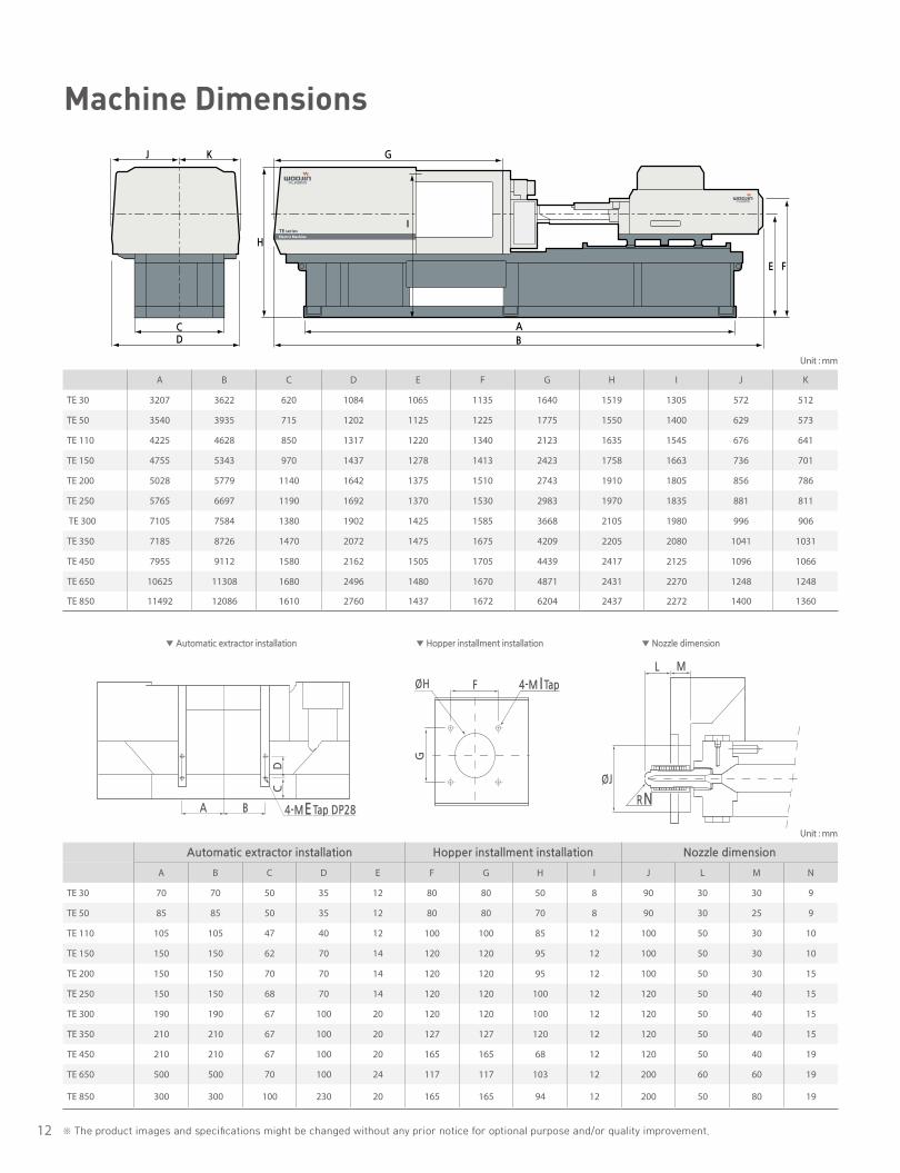
A B C D E F G H I J K
TE 30 3207 3622 620 1084 1065 1135 1640 1519 1305 572 512
TE 50 3540 3935 715 1202 1125 1225 1775 1550 1400 629 573
TE 110 4225 4628 850 1317 1220 1340 2123 1635 1545 676 641
TE 150 4755 5343 970 1437 1278 1413 2423 1758 1663 736 701
TE 200 5028 5779 1140 1642 1375 1510 2743 1910 1805 856 786
TE 250 5765 6697 1190 1692 1370 1530 2983 1970 1835 881 811
TE 300 7105 7584 1380 1902 1425 1585 3668 2105 1980 996 906
TE 350 7185 8726 1470 2072 1475 1675 4209 2205 2080 1041 1031
TE 450 7955 9112 1580 2162 1505 1705 4439 2417 2125 1096 1066
TE 650 10625 11308 1680 2496 1480 1670 4871 2431 2270 1248 1248
TE 850 11492 12086 1610 2760 1437 1672 6204 2437 2272 1400 1360
Unit : mm
Automatic extractor installation Hopper installment installation Nozzle dimension
A B C D E F G H I J L M N
TE 30 70 70 50 35 12 80 80 50 8 90 30 30 9
TE 50 85 85 50 35 12 80 80 70 8 90 30 25 9
TE 110 105 105 47 40 12 100 100 85 12 100 50 30 10
TE 150 150 150 62 70 14 120 120 95 12 100 50 30 10
TE 200 150 150 70 70 14 120 120 95 12 100 50 30 15
TE 250 150 150 68 70 14 120 120 100 12 120 50 40 15
TE 300 190 190 67 100 20 120 120 100 12 120 50 40 15
TE 350 210 210 67 100 20 127 127 120 12 120 50 40 15
TE 450 210 210 67 100 20 165 165 68 12 120 50 40 19
TE 650 500 500 70 100 24 117 117 103 12 200 60 60 19
TE 850 300 300 100 230 20 165 165 94 12 200 50 80 19
Unit : mm
DC
J K
H
E F
A
B
G
I
A B
CD
4-M ETap DP28
R N
L M
G
FØH 4-M I Tap
ØJ
※ The product images and specifications might be changed without any prior notice for optional purpose and/or quality improvement.
Machine Dimensions
▼ Automatic extractor installation ▼ Hopper installment installation ▼ Nozzle dimension
13
WOOJINPLAIMM
Platen Dimensions
70
46070
70
46070
310
Ø65 85
530
85
85530
85
100
100
100100
360
Ø70 4-Ø33
150 150
840
9090 17
017
0
100 100
100
100 84
0
560
Ø90
4-Ø33
100
105
630
100
105
100
100
105
630
105
410
Ø1054-Ø33
100
100
5050
200
50 50
100
100
200
200
150 150
900
900
100 100
200 200
200
610
Ø90
12-Ø33
121014
0 265
140
265
140 140
265 265
50 50100 100
200 200
5050
100
100
200
200
870
1260
Ø13012-Ø33
100
150
750
100
150
100
100
17085
750
170
85
510
Ø90
4-Ø33
140 26
514
026
5
140 140
265 265
50 50100 100
200 200
5050
100
10020
020
0
1090 (1180)
1090
(11
80)
720 (820)
Ø12012-Ø33
75
200 200
75100100
350 350
7575 50
50
200
200
350
350
100
100
175
175
175 175
325
325
1480
5050
1550
505075
225 22575
420 420685 685
200200100100
3503501720
5050
7575
100
100
200
200
350
350
175
175
325
325
420
420
1080
Ø120
12-Ø408-Ø60
Ø12 0
12-Ø40
8-Ø60
1180
1720
820
650 ton

14 ※ The product images and specifications might be changed without any prior notice for optional purpose and/or quality improvement.
DL 450S DL 550S DL 650S DL 850S DL 1050S DL 1300S DL 1800S DL 2000S DL 2500S DL 3000S DL 3500S DL 3500S
IH 2800 IH 4200 IH 5900 IH 8800 IH 8800 IH 11900 IH 15300 IH 15300 IH 21500 IH 31700 IH 66300 IH 100200
Injection Unit
Screw & Barrel Type O A B O A B O A B O A B O A B A B A B A B A B A B A B A B
Screw diameter mm 65 70 80 70 80 90 80 90 105 95 105 115 95 105 115 115 125 125 140 125 140 140 160 160 180 200 220 230 250
Injection pressurekg/cm² 2191 1889 1446 2465 1887 1491 2386 1885 1385 2145 1756 1464 2145 1756 1464 1809 1531 1814 1446 1814 1446 1816 1391 1792 1416 1744 1441 1753 1484
Mpa 215 185 142 242 185 146 234 185 136 210 172 144 210 172 144 177 150 178 142 178 142 178 136 176 139 171 141 172 146
Theorectical injection volume cm³ 1270 1480 1930 1690 2210 2790 2480 3140 4280 4110 5020 6020 4110 5020 6020 6570 7760 8430 10580 8430 10580 11850 15480 17690 22390 38013 45996 57128 67495
Shot weight g 1170 1364 1778 1557 2037 2571 2285 2894 3944 3787 4626 5547 3787 4626 5547 6054 7151 7768 9749 7768 9749 10920 14265 16301 20632 35029 42385 52643 62197
Injection rate(Standard) cm³/s 457 531 693 493 644 815 633 801 1090 844 1031 1236 844 1031 1236 1275 1506 1271 1595 1271 1595 1547 2020 1649 2087 2299 2781 2918 3448
Screw stroke mm 385 385 385 440 440 440 495 495 495 583 583 583 583 583 583 632 632 687 687 687 687 770 770 885 885 1210 1210 1375 1375
Injection speed(standard) mm/s 138 138 138 128 128 128 126 126 126 119 119 119 119 119 119 123 123 104 104 104 104 100 100 82 82 73 73 70 70
Plasticizing capacity kg/h 254 277 342 277 342 394 342 394 495 400 495 564 400 495 564 564 627 627 745 627 745 701 843 799 974 1132 1298 1318 1452
Screw rotation rpm 195 185 165 185 165 145 160 145 125 130 125 115 130 125 115 115 105 105 95 105 95 90 80 76 71 65 60 55 50
Clamping Unit
Clamping force ton(kN) 450(4413) 550(5394) 650(6374) 850(8336) 1050(10297) 1300(12749) 1800(17652) 2000(19613) 2500(24517) 3000(29420) 3500(34323) 3500(34323)
Mold opening force ton(kN) 31(304) 38(373) 45(441) 58(569) 74(726) 89(873) 124(1216) 138(1353) 166(1628) 200(1961) 206(2020) 206(2020)
Distance between tie-bar (H × V) mm 860 × 810 915 × 915 1010 × 1010 1110 × 1110 1410 × 1110 1410 × 1410 1610 × 1610 1810 × 1610 1820 × 1620 1920 × 1820 2320 × 1920 2320 × 1920
Platen size (H × V) mm 1240 × 1190 1330 × 1330 1460 × 1460 1610 × 1610 1950 × 1650 1950 × 1950 2150 × 2150 2450 × 2150 2500 × 2300 2550 × 2450 3200 × 2800 3200 × 2800
Daylight mm 1450 1600 1800 2300 2400 2500 3200 3200 3600 3800 4000 4000
Min. mold height mm 350 400 450 500 600 700 800 800 900 1000 1000 1000
Max. mold height mm 800 950 1100 1200 1200 1200 1500 1500 1700 1900 2000 2000
Ejector force ton(kN) 11.1(109) 16.6(163) 19.8(194) 26.9(264) 26.9(264) 34.4(345) 44.5(437) 44.5(437) 67.8(665) 68.7(674) 67.8(665) 67.8(665)
Ejector stroke mm 200 220 250 250 250 300 300 300 350 350 350 350
General
Total heat capacity kW 18.5 20.7 24.2 23 26.8 30.6 29.4 33.6 39.3 39.7 44.6 49.6 39.7 44.6 49.6 54.6 58.1 61.9 71.1 61.9 71.1 78.4 91.1 106.3 123.4 157 178 215 240
Electric motor power capacity(Standard) kW 78.0 92.4 124.7 137.4 137.4 181.3 181.3 181.3 226.4 238.0 313.0 397.3
Total Electric Power capacity(Standard) kW 96.5 98.7 102.2 115.4 119.2 123 154.1 158.3 164 177.1 182 187 177.1 182 187 235.9 239.4 243.2 252.4 243.2 252.4 304.8 317.5 344.3 361.4 470 491 612 637
Total oil reservoir capacity l 950 1200 1500 1800 1800 2500 3200 3200 4200 4500 5000 5500
Machine weight ton 19 26 32 41 52 66 95 110 130 150 233 245
Machine dimension (L × W × H) m 6.7 × 2.4 × 2.2 7.6 × 2.5 × 2.2 8.3 × 2.6 × 2.4 9.5 × 2.8 × 2.5 9.7 × 3.2 × 2.5 10.7 × 3.4 × 3.0 12.3 × 3.8 × 3.3 12.3 × 4.0 × 3.3 13.9 × 4.2 × 3.6 15 × 4.4 × 4.0 17.4 × 5.1 × 4.2 18.9 × 5.1 × 4.2
Cooling water requirement l/min 130 180 180 180 180 185 185 185 240 240 240 240
DL specification
15
WOOJINPLAIMM
DL 450S DL 550S DL 650S DL 850S DL 1050S DL 1300S DL 1800S DL 2000S DL 2500S DL 3000S DL 3500S DL 3500S
IH 2800 IH 4200 IH 5900 IH 8800 IH 8800 IH 11900 IH 15300 IH 15300 IH 21500 IH 31700 IH 66300 IH 100200
Injection Unit
Screw & Barrel Type O A B O A B O A B O A B O A B A B A B A B A B A B A B A B
Screw diameter mm 65 70 80 70 80 90 80 90 105 95 105 115 95 105 115 115 125 125 140 125 140 140 160 160 180 200 220 230 250
Injection pressurekg/cm² 2191 1889 1446 2465 1887 1491 2386 1885 1385 2145 1756 1464 2145 1756 1464 1809 1531 1814 1446 1814 1446 1816 1391 1792 1416 1744 1441 1753 1484
Mpa 215 185 142 242 185 146 234 185 136 210 172 144 210 172 144 177 150 178 142 178 142 178 136 176 139 171 141 172 146
Theorectical injection volume cm³ 1270 1480 1930 1690 2210 2790 2480 3140 4280 4110 5020 6020 4110 5020 6020 6570 7760 8430 10580 8430 10580 11850 15480 17690 22390 38013 45996 57128 67495
Shot weight g 1170 1364 1778 1557 2037 2571 2285 2894 3944 3787 4626 5547 3787 4626 5547 6054 7151 7768 9749 7768 9749 10920 14265 16301 20632 35029 42385 52643 62197
Injection rate(Standard) cm³/s 457 531 693 493 644 815 633 801 1090 844 1031 1236 844 1031 1236 1275 1506 1271 1595 1271 1595 1547 2020 1649 2087 2299 2781 2918 3448
Screw stroke mm 385 385 385 440 440 440 495 495 495 583 583 583 583 583 583 632 632 687 687 687 687 770 770 885 885 1210 1210 1375 1375
Injection speed(standard) mm/s 138 138 138 128 128 128 126 126 126 119 119 119 119 119 119 123 123 104 104 104 104 100 100 82 82 73 73 70 70
Plasticizing capacity kg/h 254 277 342 277 342 394 342 394 495 400 495 564 400 495 564 564 627 627 745 627 745 701 843 799 974 1132 1298 1318 1452
Screw rotation rpm 195 185 165 185 165 145 160 145 125 130 125 115 130 125 115 115 105 105 95 105 95 90 80 76 71 65 60 55 50
Clamping Unit
Clamping force ton(kN) 450(4413) 550(5394) 650(6374) 850(8336) 1050(10297) 1300(12749) 1800(17652) 2000(19613) 2500(24517) 3000(29420) 3500(34323) 3500(34323)
Mold opening force ton(kN) 31(304) 38(373) 45(441) 58(569) 74(726) 89(873) 124(1216) 138(1353) 166(1628) 200(1961) 206(2020) 206(2020)
Distance between tie-bar (H × V) mm 860 × 810 915 × 915 1010 × 1010 1110 × 1110 1410 × 1110 1410 × 1410 1610 × 1610 1810 × 1610 1820 × 1620 1920 × 1820 2320 × 1920 2320 × 1920
Platen size (H × V) mm 1240 × 1190 1330 × 1330 1460 × 1460 1610 × 1610 1950 × 1650 1950 × 1950 2150 × 2150 2450 × 2150 2500 × 2300 2550 × 2450 3200 × 2800 3200 × 2800
Daylight mm 1450 1600 1800 2300 2400 2500 3200 3200 3600 3800 4000 4000
Min. mold height mm 350 400 450 500 600 700 800 800 900 1000 1000 1000
Max. mold height mm 800 950 1100 1200 1200 1200 1500 1500 1700 1900 2000 2000
Ejector force ton(kN) 11.1(109) 16.6(163) 19.8(194) 26.9(264) 26.9(264) 34.4(345) 44.5(437) 44.5(437) 67.8(665) 68.7(674) 67.8(665) 67.8(665)
Ejector stroke mm 200 220 250 250 250 300 300 300 350 350 350 350
General
Total heat capacity kW 18.5 20.7 24.2 23 26.8 30.6 29.4 33.6 39.3 39.7 44.6 49.6 39.7 44.6 49.6 54.6 58.1 61.9 71.1 61.9 71.1 78.4 91.1 106.3 123.4 157 178 215 240
Electric motor power capacity(Standard) kW 78.0 92.4 124.7 137.4 137.4 181.3 181.3 181.3 226.4 238.0 313.0 397.3
Total Electric Power capacity(Standard) kW 96.5 98.7 102.2 115.4 119.2 123 154.1 158.3 164 177.1 182 187 177.1 182 187 235.9 239.4 243.2 252.4 243.2 252.4 304.8 317.5 344.3 361.4 470 491 612 637
Total oil reservoir capacity l 950 1200 1500 1800 1800 2500 3200 3200 4200 4500 5000 5500
Machine weight ton 19 26 32 41 52 66 95 110 130 150 233 245
Machine dimension (L × W × H) m 6.7 × 2.4 × 2.2 7.6 × 2.5 × 2.2 8.3 × 2.6 × 2.4 9.5 × 2.8 × 2.5 9.7 × 3.2 × 2.5 10.7 × 3.4 × 3.0 12.3 × 3.8 × 3.3 12.3 × 4.0 × 3.3 13.9 × 4.2 × 3.6 15 × 4.4 × 4.0 17.4 × 5.1 × 4.2 18.9 × 5.1 × 4.2
Cooling water requirement l/min 130 180 180 180 180 185 185 185 240 240 240 240
1. Theoretical injection volume : screw cross section area × screw stroke.3. Specifications can be changed for improvement without prior notice.
2. Minimum mold size must be over 60% of distance between tie-bar.
16
R19
50
ØM
I
H/2
H
G/2
G/2G
ØK
H/2
J
AA BB
E
D
C
F R19
50
ØM
I
H/2
H
G/2
G/2G
ØK
H/2
J
AA BB
E
D
C
F R19
50
ØM
I
H/2
H
G/2
G/2G
ØK
H/2
J
AA BB
E
D
C
F
C
KJ I
E
F
G H
ABD
Automatic extractor installation Hopper installment installation Nozzle dimension
A B C D E F G H I J K M
DL 450S 210 105 185 4-M20 165 165 120 4-M12 68 100
DL 550S 195 105 245 4-M20 165 165 130 4-M12 78 100
DL 650S 235 110 265 4-M24 165 165 140 4-M12 88 100
DL 850S 235 115 330 4-M24 165 165 170 4-M12 103 100
DL 1050S 335 125 375 4-M30 165 165 170 4-M12 103 100
DL 1300S 535 100 130 150 150 12-M20 280 200 190 4-M16 113 120
DL 1800S 725 450 150 150 150 12-M30 280 200 200 4-M16 123 120
DL 2000S 830 450 150 150 150 12-M30 280 200 200 4-M16 123 120
DL 2500S 850 450 170 200 200 12-M30 280 200 220 4-M16 138 120
DL 3000S 900 500 260 250 250 12-M30 280 200 240 4-M16 158 120
DL 3500S-IH66300 1115 500 165 300 300 12-M30 280 200 300 4-M16 196 120
DL 3500S-IH100200 1115 500 165 300 300 12-M30 280 200 345 4-M16 228 120
A B C D E F G H I J K
DL 450S 6692 6692 1280 2307 2097 867 1410 2105 2715 1277 1030
DL 550S 7564 7564 1330 2422 2177 867 1410 2190 2974 1337 1085
DL 650S 8260 8260 1430 2598 2292 868 1450 2305 3248 1428 1170
DL 850S 9475 9475 1610 2794 2407 868 1490 2435 3880 1489 1305
DL 1050S 9635 9635 1910 3133 2382 868 1490 2475 4040 1658 1474
DL 1300S 10652 10652 1890 3373 2560 989 1720 2915 4470 1687 1687
DL 1800S 12207 12207 2170 3724 2835 1023 1890 3265 5240 1862 1862
DL 2000S 12257 12257 2380 3934 2835 1023 1890 3295 5290 1967 1967
DL 2500S 13844 13844 2480 4154 3120 1220 2085 3568 6032 2102 2052
DL 3000S 15000 15000 2670 4378 3353 1358 2235 3873 6342 2194 2184
DL 3500S-IH66300 17340 17340 3170 5013 3520 1561 2435 4185 6732 2521.6 2491.6
DL 3500S-IH100200 18849 18849 3170 5013 3520 1485 2435 4185 6732 2521.6 2491.6
* These machines’ dimension are based on from 450S to 1300S as standard features and it may differ from other clamping tonnage model in figures and appearance.
※ The product images and specifications might be changed without any prior notice for optional purpose and/or quality improvement.
Machine Dimensions
▼ Automatic extractor installation ▼ Hopper installment installation ▼ Nozzle dimension
17
WOOJINPLAIMM
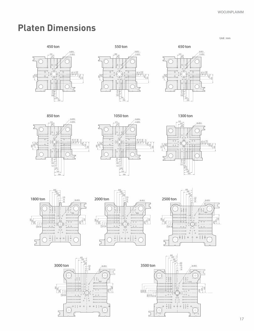
200325
350
50 75 100
125
350
200
180
300
5075100
400
500
125
500
200
16-Ø5312-Ø33
225375
350
50 75 100
125
350
200
180
300
5075100
400
500
125
500
200
16-Ø5312-Ø33
200325
350
50 75 100
200
350200
200
325
5075
100
8-Ø5312-Ø33
350
140280
350
50 75 100
200
200
140
280
5075
100
8-Ø5312-Ø33
200350
525
500
50 75 125
200
35020020
035
0
5075
125
525
500650
350
28-Ø53
200 37
5 550
5075125
20035
0500
7550
125200
350500
650
700
28-Ø53
125250
350
50 75 100
200
350200
125
250
5075
100
8-Ø5312-Ø33
200 37
5 550
5075
125200
350500
650
50125
20035
0500
75
850
28-Ø53
1257550
200 37
5 550
5075125
20035
0500
200350
500650
850
28-Ø53
5075
125200
350500
650
250 42
5 600
50125
20035
0500
75
850
28-Ø53 36-Ø53
5075
125200
350500
650840
5075125
175
200
350
500
250 45
0 650
650
1175
Platen Dimensions
18
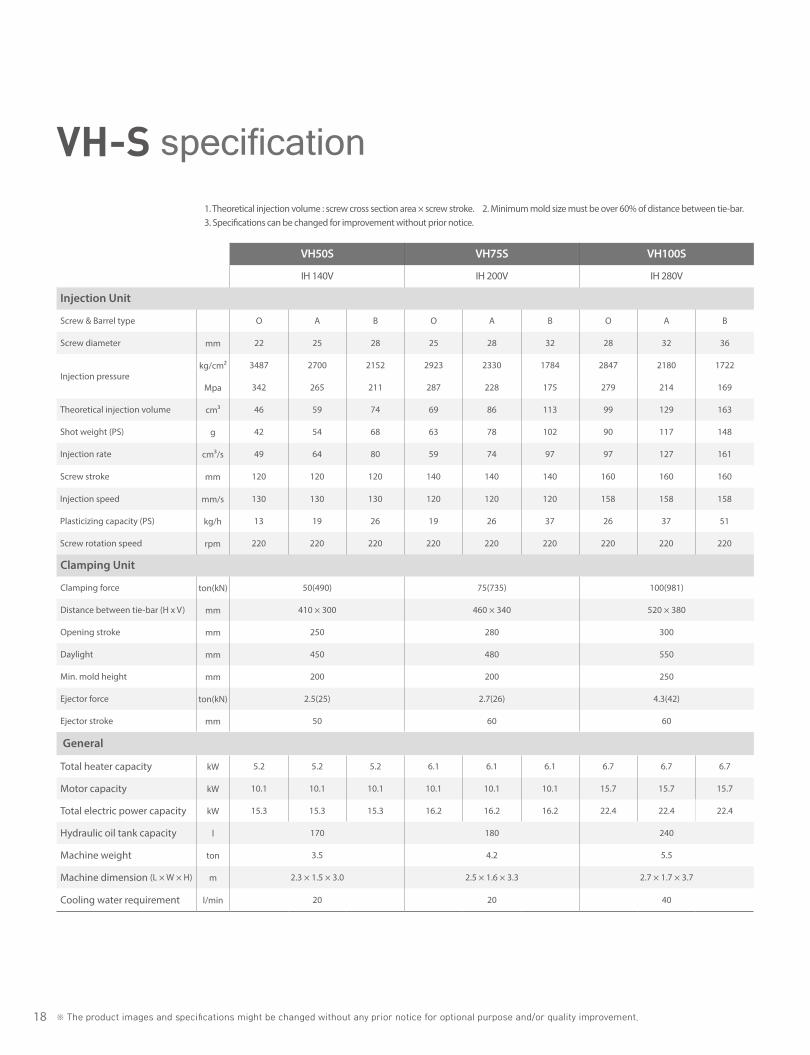
VH50S VH75S VH100S
IH 140V IH 200V IH 280V
Injection Unit
Screw & Barrel type O A B O A B O A B
Screw diameter mm 22 25 28 25 28 32 28 32 36
Injection pressurekg/cm² 3487 2700 2152 2923 2330 1784 2847 2180 1722
Mpa 342 265 211 287 228 175 279 214 169
Theoretical injection volume cm3 46 59 74 69 86 113 99 129 163
Shot weight (PS) g 42 54 68 63 78 102 90 117 148
Injection rate cm³/s 49 64 80 59 74 97 97 127 161
Screw stroke mm 120 120 120 140 140 140 160 160 160
Injection speed mm/s 130 130 130 120 120 120 158 158 158
Plasticizing capacity (PS) kg/h 13 19 26 19 26 37 26 37 51
Screw rotation speed rpm 220 220 220 220 220 220 220 220 220
Clamping Unit
Clamping force ton(kN) 50(490) 75(735) 100(981)
Distance between tie-bar (H x V) mm 410 × 300 460 × 340 520 × 380
Opening stroke mm 250 280 300
Daylight mm 450 480 550
Min. mold height mm 200 200 250
Ejector force ton(kN) 2.5(25) 2.7(26) 4.3(42)
Ejector stroke mm 50 60 60
General
Total heater capacity kW 5.2 5.2 5.2 6.1 6.1 6.1 6.7 6.7 6.7
Motor capacity kW 10.1 10.1 10.1 10.1 10.1 10.1 15.7 15.7 15.7
Total electric power capacity kW 15.3 15.3 15.3 16.2 16.2 16.2 22.4 22.4 22.4
Hydraulic oil tank capacity l 170 180 240
Machine weight ton 3.5 4.2 5.5
Machine dimension (L × W × H) m 2.3 × 1.5 × 3.0 2.5 × 1.6 × 3.3 2.7 × 1.7 × 3.7
Cooling water requirement l/min 20 20 40
※ The product images and specifications might be changed without any prior notice for optional purpose and/or quality improvement.
VH-S specification1. Theoretical injection volume : screw cross section area × screw stroke.3. Specifications can be changed for improvement without prior notice.
2. Minimum mold size must be over 60% of distance between tie-bar.
19
WOOJINPLAIMM
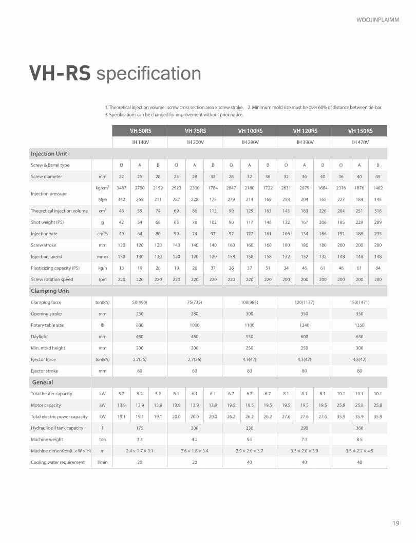
VH 50RS VH 75RS VH 100RS VH 120RS VH 150RS
IH 140V IH 200V IH 280V IH 390V IH 470V
Injection Unit
Screw & Barrel type O A B O A B O A B O A B O A B
Screw diameter mm 22 25 28 25 28 32 28 32 36 32 36 40 36 40 45
Injection pressurekg/cm² 3487 2700 2152 2923 2330 1784 2847 2180 1722 2631 2079 1684 2316 1876 1482
Mpa 342 265 211 287 228 175 279 214 169 258 204 165 227 184 145
Theoretical injection volume cm³ 46 59 74 69 86 113 99 129 163 145 183 226 204 251 318
Shot weight (PS) g 42 54 68 63 78 102 90 117 148 132 167 206 185 229 289
Injection rate cm³/s 49 64 80 59 74 97 97 127 161 106 134 166 151 186 235
Screw stroke mm 120 120 120 140 140 140 160 160 160 180 180 180 200 200 200
Injection speed mm/s 130 130 130 120 120 120 158 158 158 132 132 132 148 148 148
Plasticizing capacity (PS) kg/h 13 19 26 19 26 37 26 37 51 34 46 61 46 61 84
Screw rotation speed rpm 220 220 220 220 220 220 220 220 220 200 200 200 200 200 200
Clamping Unit
Clamping force ton(kN) 50(490) 75(735) 100(981) 120(1177) 150(1471)
Opening stroke mm 250 280 300 350 350
Rotary table size Φ 880 1000 1100 1240 1350
Daylight mm 450 480 550 600 650
Min. mold height mm 200 200 250 250 300
Ejector force ton(kN) 2.7(26) 2.7(26) 4.3(42) 4.3(42) 4.3(42)
Ejector stroke mm 60 60 80 80 80
General
Total heater capacity kW 5.2 5.2 5.2 6.1 6.1 6.1 6.7 6.7 6.7 8.1 8.1 8.1 10.1 10.1 10.1
Motor capacity kW 13.9 13.9 13.9 13.9 13.9 13.9 19.5 19.5 19.5 19.5 19.5 19.5 25.8 25.8 25.8
Total electric power capacity kW 19.1 19.1 19.1 20.0 20.0 20.0 26.2 26.2 26.2 27.6 27.6 27.6 35.9 35.9 35.9
Hydraulic oil tank capacity l 175 200 236 290 368
Machine weight ton 3.5 4.2 5.5 7.3 8.5
Machine dimension(L × W × H) m 2.4 × 1.7 × 3.1 2.6 × 1.8 × 3.4 2.9 × 2.0 × 3.7 3.3 × 2.0 × 3.9 3.5 × 2.2 × 4.5
Cooling water requirement l/min 20 20 40 40 40
VH-RS specification1. Theoretical injection volume : screw cross section area × screw stroke.3. Specifications can be changed for improvement without prior notice.
2. Minimum mold size must be over 60% of distance between tie-bar.

20 ※ The product images and specifications might be changed without any prior notice for optional purpose and/or quality improvement.
VHA-RS specification
VHA50RS VHA75RS VHA100RS VHA120RS VHA150RS VHA200RS
IH 140V IH 200V IH 280V IH 390V IH 470V IH 740V
Injection Unit
Screw & Barrel type O A B O A B O A B O A B O A B O A B
Screw diameter mm 22 25 28 25 28 32 28 32 36 32 36 40 36 40 45 40 45 50
Injection pressurekg/cm² 3487 2700 2152 2923 2330 1784 2847 2180 1722 2631 2079 1684 2316 1876 1482 2695 2129 1725
Mpa 342 265 211 287 228 175 279 214 169 258 204 165 227 184 145 264 209 169
Theoretical injection volume cm³ 46 59 74 69 86 113 99 129 163 145 183 226 204 251 318 276 349 432
Shot weight (PS) g 42 54 68 63 78 102 90 117 148 132 167 206 185 229 289 254 322 398
Injection rate cm³/s 49 64 80 59 74 97 97 127 161 106 134 166 151 186 235 163 207 255
Screw stroke mm 120 120 120 140 140 140 160 160 160 180 180 180 200 200 200 220 220 220
Injection speed mm/s 130 130 130 120 120 120 158 158 158 132 132 132 148 148 148 130 130 130
Plasticizing capacity (PS) kg/h 13 19 26 19 26 37 26 37 51 34 46 61 46 61 84 50 68 90
Screw rotation speed rpm 220 220 220 220 220 220 220 220 220 200 200 200 200 200 200 180 180 180
Clamping Unit
Clamping force ton(kN) 50(490) 75(735) 100(981) 120(1177) 150(1471) 200(1961)
Opening stroke mm 250 250 250 300 300 300
Rotary table size Φ 880 1000 1100 1240 1350 1500
Daylight mm 450 450 500 600 650 650
Min. mold height mm 200 200 250 300 350 350
Ejector force ton(kN) 2.7(26) 2.7(26) 4.3(42) 4.3(42) 4.3(42) 5.4(53)
Ejector stroke mm 60 60 80 80 80 100
General
Total heater capacity kW 5.2 5.2 5.2 6.1 6.1 6.1 6.7 6.7 6.7 8.1 8.1 8.1 10.1 10.1 10.1 12.5 12.5 12.5
Motor capacity kW 13.9 13.9 13.9 13.9 13.9 13.9 19.5 19.5 19.5 19.5 19.5 19.5 25.8 25.8 25.8 27.5 27.5 27.5
Total electric power capacity kW 19.1 19.1 19.1 20.0 20.0 20.0 26.2 26.2 26.2 27.6 27.6 27.6 35.9 35.9 35.9 40 40 40
Hydraulic oil tank capacity l 180 180 250 300 390 450
Machine weight ton 3.5 4.2 5.5 7.3 8.5 12.3
Machine dimension (L × W × H) m 2.7 × 1.6 × 2.9 2.9 × 1.8 × 3.0 3.3 × 1.9 × 3.4 3.3 × 2.0 × 3.8 3.6 × 2.1 × 4.1 3.8 × 2.3 × 4.5
Cooling water requirement l/min 20 20 40 40 40 40
1. Theoretical injection volume : screw cross section area × screw stroke.3. Specifications can be changed for improvement without prior notice.
2. Minimum mold size must be over 60% of distance between tie-bar.
21
WOOJINPLAIMM
GI
H J
C
AB
F
ED
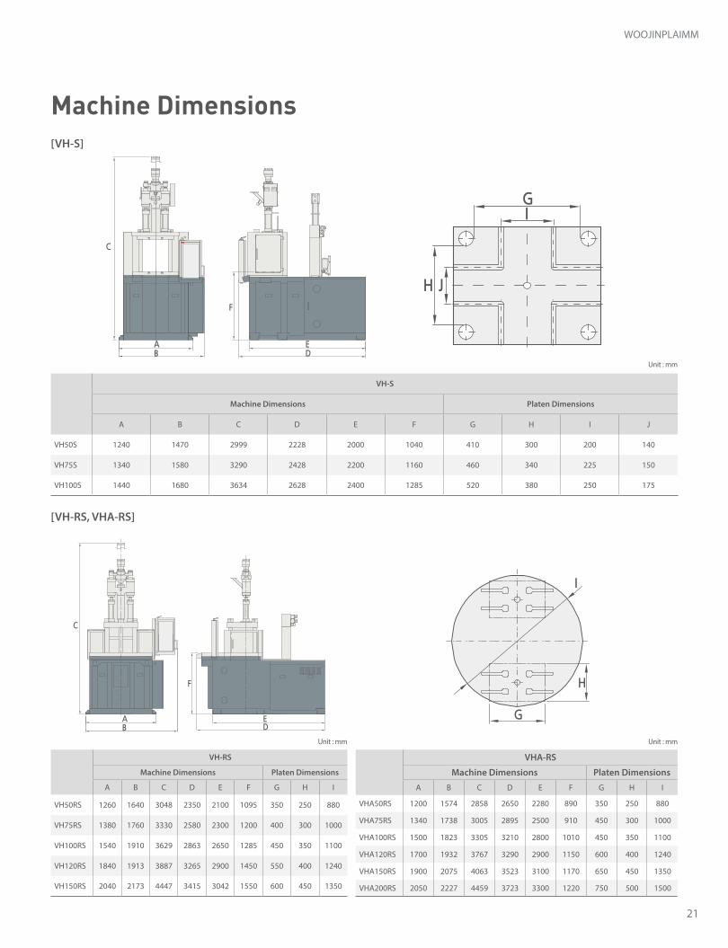
VH-S
Machine Dimensions Platen Dimensions
A B C D E F G H I J
VH50S 1240 1470 2999 2228 2000 1040 410 300 200 140
VH75S 1340 1580 3290 2428 2200 1160 460 340 225 150
VH100S 1440 1680 3634 2628 2400 1285 520 380 250 175
VH-RS
Machine Dimensions Platen Dimensions
A B C D E F G H I
VH50RS 1260 1640 3048 2350 2100 1095 350 250 880
VH75RS 1380 1760 3330 2580 2300 1200 400 300 1000
VH100RS 1540 1910 3629 2863 2650 1285 450 350 1100
VH120RS 1840 1913 3887 3265 2900 1450 550 400 1240
VH150RS 2040 2173 4447 3415 3042 1550 600 450 1350
VHA-RS
Machine Dimensions Platen Dimensions
A B C D E F G H I
VHA50RS 1200 1574 2858 2650 2280 890 350 250 880
VHA75RS 1340 1738 3005 2895 2500 910 450 300 1000
VHA100RS 1500 1823 3305 3210 2800 1010 450 350 1100
VHA120RS 1700 1932 3767 3290 2900 1150 600 400 1240
VHA150RS 1900 2075 4063 3523 3100 1170 650 450 1350
VHA200RS 2050 2227 4459 3723 3300 1220 750 500 1500
G
I
H
C
AB
F
ED
[VH-S]
[VH-RS, VHA-RS]
Machine Dimensions
22 ※ The product images and specifications might be changed without any prior notice for optional purpose and/or quality improvement.
(Table size)
Ø
Ø
Ø
Ø
Ø
Ø
(Table size)
ABD
C
E F
G I
JH
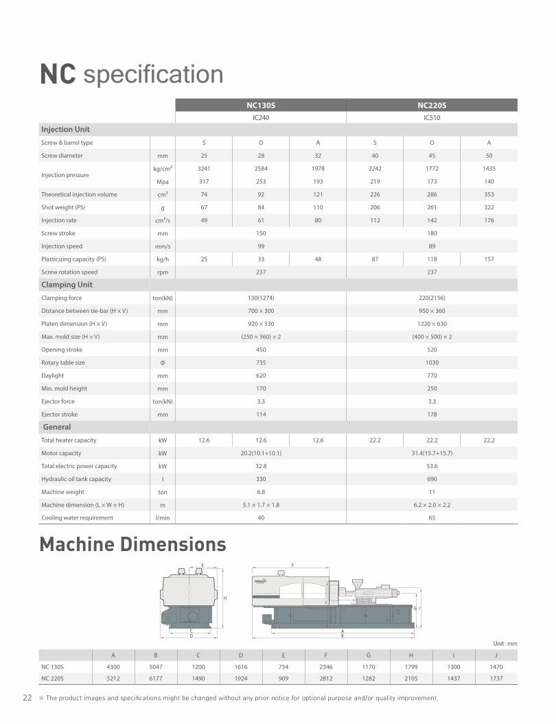
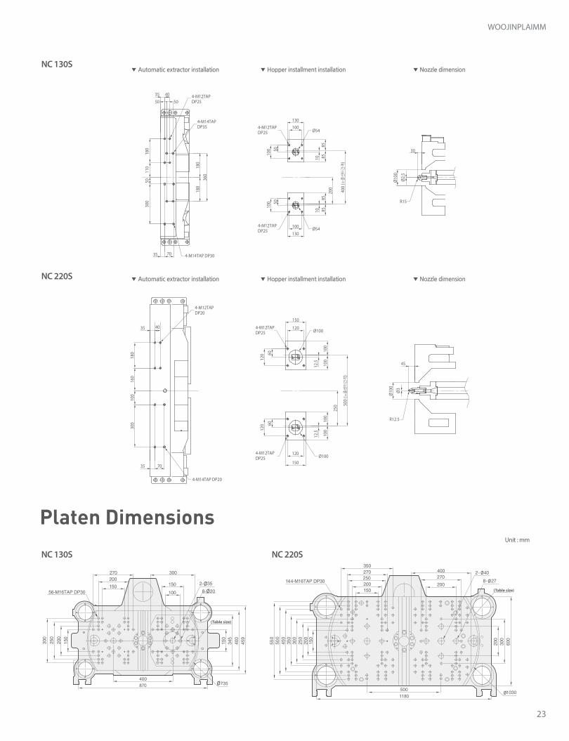
A B C D E F G H I J
NC 130S 4300 5047 1200 1616 754 2346 1170 1799 1300 1470
NC 220S 5212 6177 1490 1924 909 2812 1282 2105 1437 1737
Unit : mm
NC130S NC220SIC240 IC510
Injection Unit
Screw & barrel type S O A S O A
Screw diameter mm 25 28 32 40 45 50
Injection pressurekg/cm2 3241 2584 1978 2242 1772 1435
Mpa 317 253 193 219 173 140
Theoretical injection volume cm³ 74 92 121 226 286 353
Shot weight (PS) g 67 84 110 206 261 322
Injection rate cm³/s 49 61 80 112 142 176
Screw stroke mm 150 180
Injection speed mm/s 99 89
Plasticizing capacity (PS) kg/h 25 33 48 87 118 157
Screw rotation speed rpm 237 237
Clamping Unit
Clamping force ton(kN) 130(1274) 220(2156)
Distance between tie-bar (H × V) mm 700 × 300 950 × 360
Platen dimension (H × V) mm 920 × 530 1220 × 630
Max. mold size (H × V) mm (250 × 360) × 2 (400 × 500) × 2
Opening stroke mm 450 520
Rotary table size Φ 735 1030
Daylight mm 620 770
Min. mold height mm 170 250
Ejector force ton(kN) 3.3 3.3
Ejector stroke mm 114 178
General
Total heater capacity kW 12.6 12.6 12.6 22.2 22.2 22.2
Motor capacity kW 20.2(10.1+10.1) 31.4(15.7+15.7)
Total electric power capacity kW 32.8 53.6
Hydraulic oil tank capacity l 330 690
Machine weight ton 6.8 11
Machine dimension (L × W × H) m 5.1 × 1.7 × 1.8 6.2 × 2.0 × 2.2
Cooling water requirement l/min 40 65
NC specification
Machine Dimensions
23
WOOJINPLAIMM
Unit : mm
Platen Dimensions
▼ Automatic extractor installation
▼ Automatic extractor installation
▼ Hopper installment installation
▼ Hopper installment installation
▼ Nozzle dimension
▼ Nozzle dimension
Ø2.
5
40
130
30
R15
130
100
100
100 50
100 50
10
400
(노즐센터간격
)
200
858510
8585
Ø54
Ø54
Ø100
Ø100
Ø10
0Ø
100
35
150
120
45
R12.5
120
12.5
100
100
12.5
100
100
500
(노즐센터간격
)
250
60
120
120
150
60
180
160
100
300
35
35 70
50
110
5018
0
180
180
360
300
504-M12TAP DP25
4-M12TAP DP20
4-M12TAP DP25
4-M12TAP DP25
4-M12TAP DP25
4-M12TAP DP25
4-M14TAP DP35
35 70 4-M14TAP DP30
4-M14TAP DP20
40
Ø3
(Table size)
Ø
Ø
Ø
Ø
Ø
Ø
(Table size)
ABD
C
E F
G I
JH
(Table size)
Ø
Ø
Ø
Ø
Ø
Ø
(Table size)
ABD
C
E F
G I
JH
24 ※ The product images and specifications might be changed without any prior notice for optional purpose and/or quality improvement.
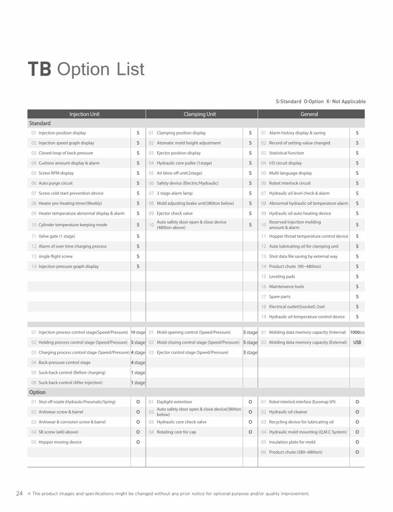
TB Option ListS:Standard O:Option X: Not Applicable
Injection Unit Clamping Unit General
Standard
01 Injection position display S 01 Clamping position display S 01 Alarm history display & saving S
02 Injection speed graph display S 02 Atomatic mold height adjustment S 02 Record of setting-value changed S
03 Closed-loop of back pressure S 03 Ejector position display S 03 Statistical function S
04 Cushion amount display & alarm S 04 Hydraulic core puller (1stage) S 04 I/O circuit display S
05 Screw RPM display S 05 Air blow off unit(2stage) S 05 Multi language display S
06 Auto purge circuit S 06 Safety device (Electric/Hydraulic) S 06 Robot interlock circuit S
07 Screw cold start prevention device S 07 3 stage alarm lamp S 07 Hydraulic oil level check & alarm S
08 Heater pre-heating timer(Weekly) S 08 Mold adjusting brake unit(380ton below) S 08 Abnormal hydraulic oil temperature alarm S
09 Heater temperature abnormal display & alarm S 09 Ejector check valve S 09 Hydraulic oil auto heating device S
10 Cylinder temperature keeping mode S 10 Auto safety door open & close device (480ton above) S 10 Reserved injection molding
amount & alarm S
11 Valve gate (1 stage) S 11 Hopper throat temperature control device S
12 Alarm of over time charging process S 12 Auto lubricating oil for clamping unit S
13 single flight screw S 13 Shot data file saving by external way S
14 Injection pressure graph display S 14 Product chute (90~480ton) S
15 Leveling pads S
16 Maintenance tools S
17 Spare parts S
18 Electrical outlet(5socket)-2set S
19 Hydraulic oil temperature control device S
01 Injection process control stage(Speed/Pressure) 10 stage 01 Mold opening control (Speed/Pressure) 5 stage 01 Molding data memory capacity (Internal) 1000ea
02 Holding process control stage (Speed/Pressure) 5 stage 02 Mold closing control stage (Speed/Pressure) 5 stage 02 Molding data memory capacity (External) USB
03 Charging process control stage (Speed/Pressure) 4 stage 03 Ejector control stage (Speed/Pressure) 3 stage
04 Back-pressure control stage 4 stage
05 Suck-back control (Before charging) 1 stage
06 Suck-back control (After injection) 1 stage
Option
01 Shut-off nozzle (Hydraulic/Pneumatic/Spring) O 01 Daylight extention O 01 Robot interlock interface (Euromap SPI) O
02 Antiwear screw & barrel O 02 Auto safety door open & close device(380ton below) O 02 Hydraulic oil cleaner O
03 Antiwear & corrosion screw & barrel O 03 Hydraulic core check valve O 03 Recycling device for lubricating oil O
04 SB screw (ø40 above) O 04 Rotating core for cap O 04 Hydraulic mold mounting (Q.M.C System) O
05 Hopper moving device O 05 Insulation plate for mold O
06 Product chute (580~680ton) O
25
WOOJINPLAIMM
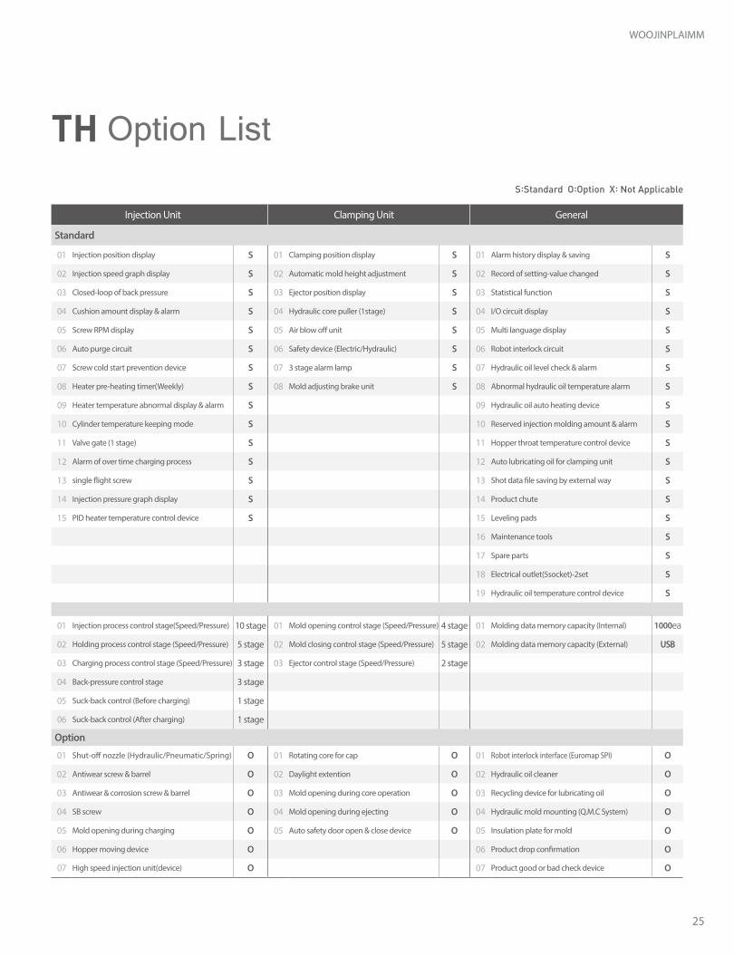
Injection Unit Clamping Unit General
Standard
01 Injection position display S 01 Clamping position display S 01 Alarm history display & saving S
02 Injection speed graph display S 02 Automatic mold height adjustment S 02 Record of setting-value changed S
03 Closed-loop of back pressure S 03 Ejector position display S 03 Statistical function S
04 Cushion amount display & alarm S 04 Hydraulic core puller (1stage) S 04 I/O circuit display S
05 Screw RPM display S 05 Air blow off unit S 05 Multi language display S
06 Auto purge circuit S 06 Safety device (Electric/Hydraulic) S 06 Robot interlock circuit S
07 Screw cold start prevention device S 07 3 stage alarm lamp S 07 Hydraulic oil level check & alarm S
08 Heater pre-heating timer(Weekly) S 08 Mold adjusting brake unit S 08 Abnormal hydraulic oil temperature alarm S
09 Heater temperature abnormal display & alarm S 09 Hydraulic oil auto heating device S
10 Cylinder temperature keeping mode S 10 Reserved injection molding amount & alarm S
11 Valve gate (1 stage) S 11 Hopper throat temperature control device S
12 Alarm of over time charging process S 12 Auto lubricating oil for clamping unit S
13 single flight screw S 13 Shot data file saving by external way S
14 Injection pressure graph display S 14 Product chute S
15 PID heater temperature control device S 15 Leveling pads S
16 Maintenance tools S
17 Spare parts S
18 Electrical outlet(5socket)-2set S
19 Hydraulic oil temperature control device S
01 Injection process control stage(Speed/Pressure) 10 stage 01 Mold opening control stage (Speed/Pressure) 4 stage 01 Molding data memory capacity (Internal) 1000ea
02 Holding process control stage (Speed/Pressure) 5 stage 02 Mold closing control stage (Speed/Pressure) 5 stage 02 Molding data memory capacity (External) USB
03 Charging process control stage (Speed/Pressure) 3 stage 03 Ejector control stage (Speed/Pressure) 2 stage
04 Back-pressure control stage 3 stage
05 Suck-back control (Before charging) 1 stage
06 Suck-back control (After charging) 1 stage
Option
01 Shut-off nozzle (Hydraulic/Pneumatic/Spring) O 01 Rotating core for cap O 01 Robot interlock interface (Euromap SPI) O
02 Antiwear screw & barrel O 02 Daylight extention O 02 Hydraulic oil cleaner O
03 Antiwear & corrosion screw & barrel O 03 Mold opening during core operation O 03 Recycling device for lubricating oil O
04 SB screw O 04 Mold opening during ejecting O 04 Hydraulic mold mounting (Q.M.C System) O
05 Mold opening during charging O 05 Auto safety door open & close device O 05 Insulation plate for mold O
06 Hopper moving device O 06 Product drop confirmation O
07 High speed injection unit(device) O 07 Product good or bad check device O
S:Standard O:Option X: Not Applicable
TH Option List
26 ※ The product images and specifications might be changed without any prior notice for optional purpose and/or quality improvement.
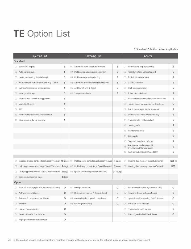
Injection Unit Clamping Unit General
Standard
01 Screw RPM display S 01 Automatic mold height adjustment S 01 Alarm history display & saving S
02 Auto purge circuit S 02 Mold opening during core operation S 02 Record of setting-value changed S
03 Heater pre-heating timer(Weekly) S 03 Mold opening during ejecting S 03 Statistical function(1000) S
04 Heater temperature abnormal display & alarm S 04 Automatic adjustment of clamping force S 04 I/O circuit display S
05 Cylinder temperature keeping mode S 05 Air blow off unit (2 stage) S 05 Multi language display S
06 Valve gate (1 stage) S 06 3 stage alarm lamp S 06 Robot interlock circuit S
07 Alarm of over time charging process S 07 Reserved injection molding amount & alarm S
08 single flight screw S 08 Hopper throat temperature control device S
09 SPC S 09 Auto lubricating oil for clamping unit S
10 PID heater temperature control device S 10 Shot data file saving by external way S
11 Mold opening during charging S 11 Product chute (450ton below) S
12 Leveling pads S
13 Maintenance tools S
14 Spare parts S
15 Electrical outlet(5socket)-2set S
16 Auto grease for clamping unit (injection unit/clamping unit) S
17 Electrical outlet(Single Phase 220V) S
01 Injection process control stage(Speed/Pressure) 10 stage 01 Mold opening control stage (Speed/Pressure) 4 stage 01 Molding data memory capacity (Internal) 1000 ea
02 Holding process control stage (Speed/Pressure) 5 stage 02 Mold closing control stage (Speed/Pressure) 5 stage 02 Molding data memory capacity (External) USB
03 Charging process control stage (Speed/Pressure) 3 stage 03 Ejector control stage (Speed/Pressure) 2+1 stage
04 Back-pressure control stage 3 stage
Option
01 Shut-off nozzle (Hydraulic/Pneumatic/Spring) O 01 Daylight extention O 01 Robot interlock interface (Euromap 67/SPI) O
02 Antiwear screw & barrel O 02 Hydraulic core puller (1 stage/2 stage) O 02 Recycling device for lubricating oil O
03 Antiwear & corrosion screw & barrel O 03 Auto safety door open & close device O 03 Hydraulic mold mounting (Q.M.C System) O
04 SB screw O 04 Rotating core for cap O 04 Insulation plate for mold O
05 Hopper moving device O 05 Product drop confirmation O
06 Heater disconnection detector O 06 Product good or bad check device O
07 High speed injection unit(device) O
S:Standard O:Option X: Not Applicable
TE Option List
27
WOOJINPLAIMM
Injection Unit 450~ 850
1050~ 3500 Clamping Unit 450~
8501050~ 3500 General 450~
8501050~ 3500
Standard
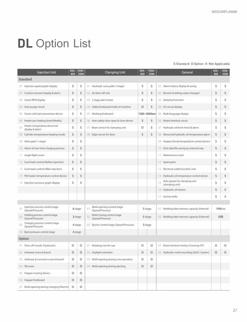
01 Injection speed graph display S S 01 Hydraulic core puller (1stage) S S 01 Alarm history display & saving S S
02 Cushion amount display & alarm S S 02 Air blow off unit S S 02 Record of setting-value changed S S
03 Screw RPM display S S 03 3 stage alarm lamp S S 03 Statistical function S S
04 Auto purge circuit S S 04 Safety footboard inside of machine O S 04 I/O circuit display S S
05 Screw cold start prevention device S S 05 Working footboard 1300~3000ton 05 Multi language display S S
06 Heater pre-heating timer(Weekly) S S 06 Auto safety door open & close device S S 06 Robot interlock circuit S S
07 Heater temperature abnormal display & alarm S S 07 Beam sensor for clamping unit O S 07 Hydraulic oil level check & alarm S S
08 Cylinder temperature keeping mode S S 08 Edge sensor for door S S 08 Abnormal hydraulic oil temperature alarm S S
09 Valve gate (1 stage) S S 09 Hopper throat temperature control device S S
10 Alarm of over time charging process S S 10 Shot data file saving by external way S S
11 single flight screw S S 11 Maintenance tools S S
12 Suck-back control (Before injection) S S 12 Spare parts S S
13 Suck-back control (After injection) S S 13 Electrical outlet(5socket)-2set S S
14 PID heater temperature control device S S 14 Hydraulic oil temperature control device S S
15 Injection pressure graph display S S 15 Auto grease for clamping unit (clamping unit) S S
16 Hydraulic oil cleaner S S
17 Anchor bolts S S
01 Injection process control stage(Speed/Pressure) 6 stage 01 Mold opening control stage
(Speed/Pressure) 5 stage 01 Molding data memory capacity (Internal) 1000 ea
02 Holding process control stage (Speed/Pressure) 3 stage 02 Mold closing control stage
(Speed/Pressure) 5 stage 02 Molding data memory capacity (External) USB
03 Charging process control stage (Speed/Pressure) 4 stage 03 Ejector control stage (Speed/Pressure) 3 stage
04 Back-pressure control stage 4 stage
Option
01 Shut-off nozzle (Hydraulic) O O 01 Rotating core for cap O O 01 Robot interlock interface (Euromap SPI) O O
02 Antiwear screw & barrel O O 02 Daylight extention O O 02 Hydraulic mold mounting (Q.M.C System) O O
03 Antiwear & corrosion screw & barrel O O 03 Mold opening during core operation O O
04 SB screw O O 04 Mold opening during ejecting O O
05 Hopper moving device O O
06 Hopper footboard O O
07 Mold opening during charging (Electric) O O
DL Option ListS:Standard O:Option X: Not Applicable
28 ※ The product images and specifications might be changed without any prior notice for optional purpose and/or quality improvement.
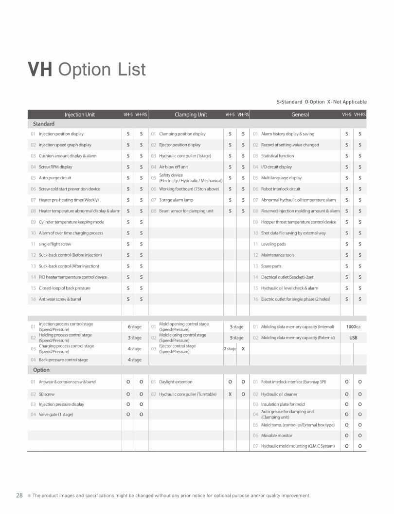
VH Option ListS:Standard O:Option X: Not Applicable
Injection Unit VH-S VH-RS Clamping Unit VH-S VH-RS General VH-S VH-RS
Standard
01 Injection position display S S 01 Clamping position display S S 01 Alarm history display & saving S S
02 Injection speed graph display S S 02 Ejector position display S S 02 Record of setting-value changed S S
03 Cushion amount display & alarm S S 03 Hydraulic core puller (1stage) S S 03 Statistical function S S
04 Screw RPM display S S 04 Air blow off unit S S 04 I/O circuit display S S
05 Auto purge circuit S S 05 Safety device (Electricity / Hydraulic / Mechanical) S S 05 Multi language display S S
06 Screw cold start prevention device S S 06 Working footboard (75ton above) S S 06 Robot interlock circuit S S
07 Heater pre-heating timer(Weekly) S S 07 3 stage alarm lamp S S 07 Abnormal hydraulic oil temperature alarm S S
08 Heater temperature abnormal display & alarm S S 08 Beam sensor for clamping unit S S 08 Reserved injection molding amount & alarm S S
09 Cylinder temperature keeping mode S S 09 Hopper throat temperature control device S S
10 Alarm of over time charging process S S 10 Shot data file saving by external way S S
11 single flight screw S S 11 Leveling pads S S
12 Suck-back control (Before injection) S S 12 Maintenance tools S S
13 Suck-back control (After injection) S S 13 Spare parts S S
14 PID heater temperature control device S S 14 Electrical outlet(5socket)-2set S S
15 Closed-loop of back pressure S S 15 Hydraulic oil level check & alarm S S
16 Antiwear screw & barrel S S 16 Electric outlet for single phase (2 holes) S S
01 Injection process control stage(Speed/Pressure) 6 stage 01 Mold opening control stage
(Speed/Pressure) 5 stage 01 Molding data memory capacity (Internal) 1000ea
02 Holding process control stage (Speed/Pressure) 3 stage 02 Mold closing control stage
(Speed/Pressure) 5 stage 02 Molding data memory capacity (External) USB
03 Charging process control stage (Speed/Pressure) 4 stage 03 Ejector control stage
(Speed/Pressure)2 stage X
04 Back-pressure control stage 4 stage
Option
01 Antiwear & corrosion screw & barrel O O 01 Daylight extention O O 01 Robot interlock interface (Euromap SPI) O O
02 SB screw O O 02 Hydraulic core puller (Turntable) X O 02 Hydraulic oil cleaner O O
03 Injection pressure display O O 03 Insulation plate for mold O O
04 Valve gate (1 stage) O O 04 Auto grease for clamping unit (Clamping unit) O O
05 Mold temp. (controller/External box type) O O
06 Movable monitor O O
07 Hydraulic mold mounting (Q.M.C System) O O
29
WOOJINPLAIMM
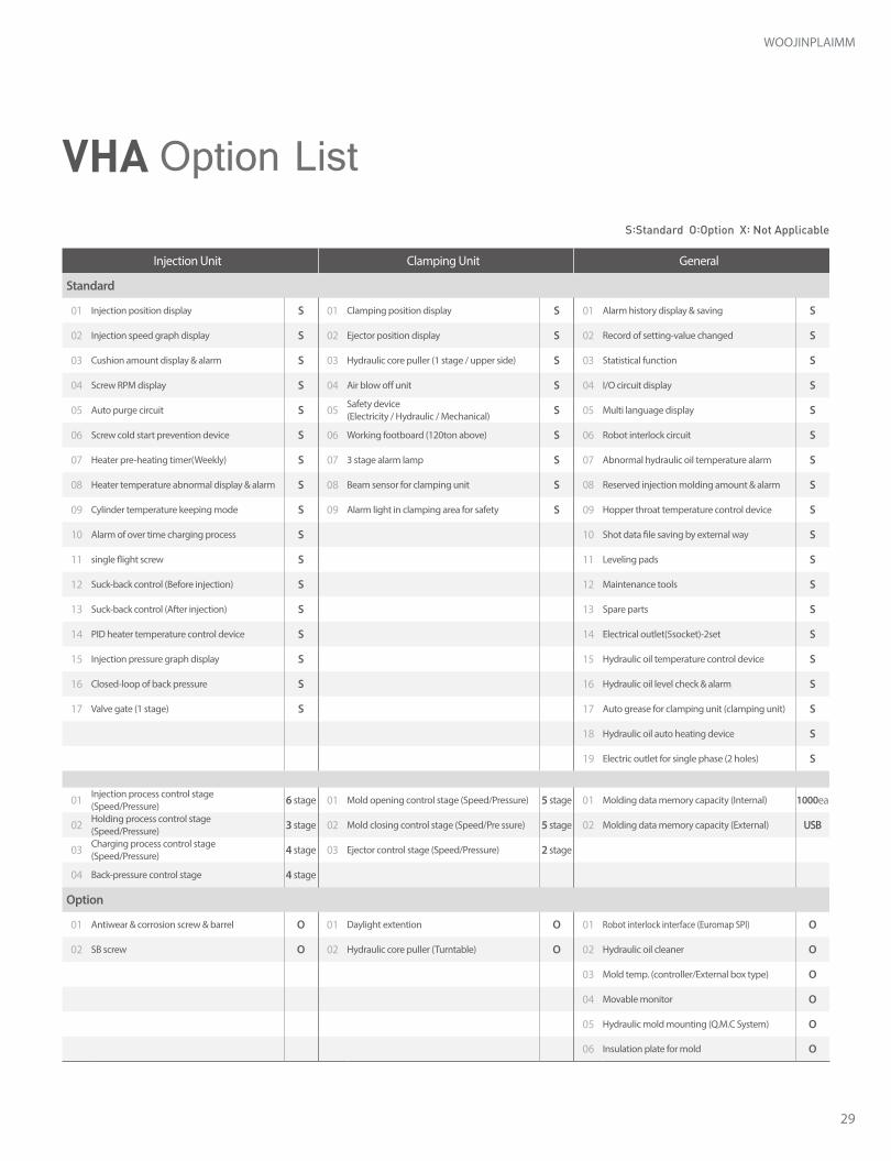
Injection Unit Clamping Unit General
Standard
01 Injection position display S 01 Clamping position display S 01 Alarm history display & saving S
02 Injection speed graph display S 02 Ejector position display S 02 Record of setting-value changed S
03 Cushion amount display & alarm S 03 Hydraulic core puller (1 stage / upper side) S 03 Statistical function S
04 Screw RPM display S 04 Air blow off unit S 04 I/O circuit display S
05 Auto purge circuit S 05 Safety device (Electricity / Hydraulic / Mechanical) S 05 Multi language display S
06 Screw cold start prevention device S 06 Working footboard (120ton above) S 06 Robot interlock circuit S
07 Heater pre-heating timer(Weekly) S 07 3 stage alarm lamp S 07 Abnormal hydraulic oil temperature alarm S
08 Heater temperature abnormal display & alarm S 08 Beam sensor for clamping unit S 08 Reserved injection molding amount & alarm S
09 Cylinder temperature keeping mode S 09 Alarm light in clamping area for safety S 09 Hopper throat temperature control device S
10 Alarm of over time charging process S 10 Shot data file saving by external way S
11 single flight screw S 11 Leveling pads S
12 Suck-back control (Before injection) S 12 Maintenance tools S
13 Suck-back control (After injection) S 13 Spare parts S
14 PID heater temperature control device S 14 Electrical outlet(5socket)-2set S
15 Injection pressure graph display S 15 Hydraulic oil temperature control device S
16 Closed-loop of back pressure S 16 Hydraulic oil level check & alarm S
17 Valve gate (1 stage) S 17 Auto grease for clamping unit (clamping unit) S
18 Hydraulic oil auto heating device S
19 Electric outlet for single phase (2 holes) S
01 Injection process control stage(Speed/Pressure) 6 stage 01 Mold opening control stage (Speed/Pressure) 5 stage 01 Molding data memory capacity (Internal) 1000ea
02 Holding process control stage (Speed/Pressure) 3 stage 02 Mold closing control stage (Speed/Pre ssure) 5 stage 02 Molding data memory capacity (External) USB
03 Charging process control stage (Speed/Pressure) 4 stage 03 Ejector control stage (Speed/Pressure) 2 stage
04 Back-pressure control stage 4 stage
Option
01 Antiwear & corrosion screw & barrel O 01 Daylight extention O 01 Robot interlock interface (Euromap SPI) O
02 SB screw O 02 Hydraulic core puller (Turntable) O 02 Hydraulic oil cleaner O
03 Mold temp. (controller/External box type) O
04 Movable monitor O
05 Hydraulic mold mounting (Q.M.C System) O
06 Insulation plate for mold O
VHA Option ListS:Standard O:Option X: Not Applicable
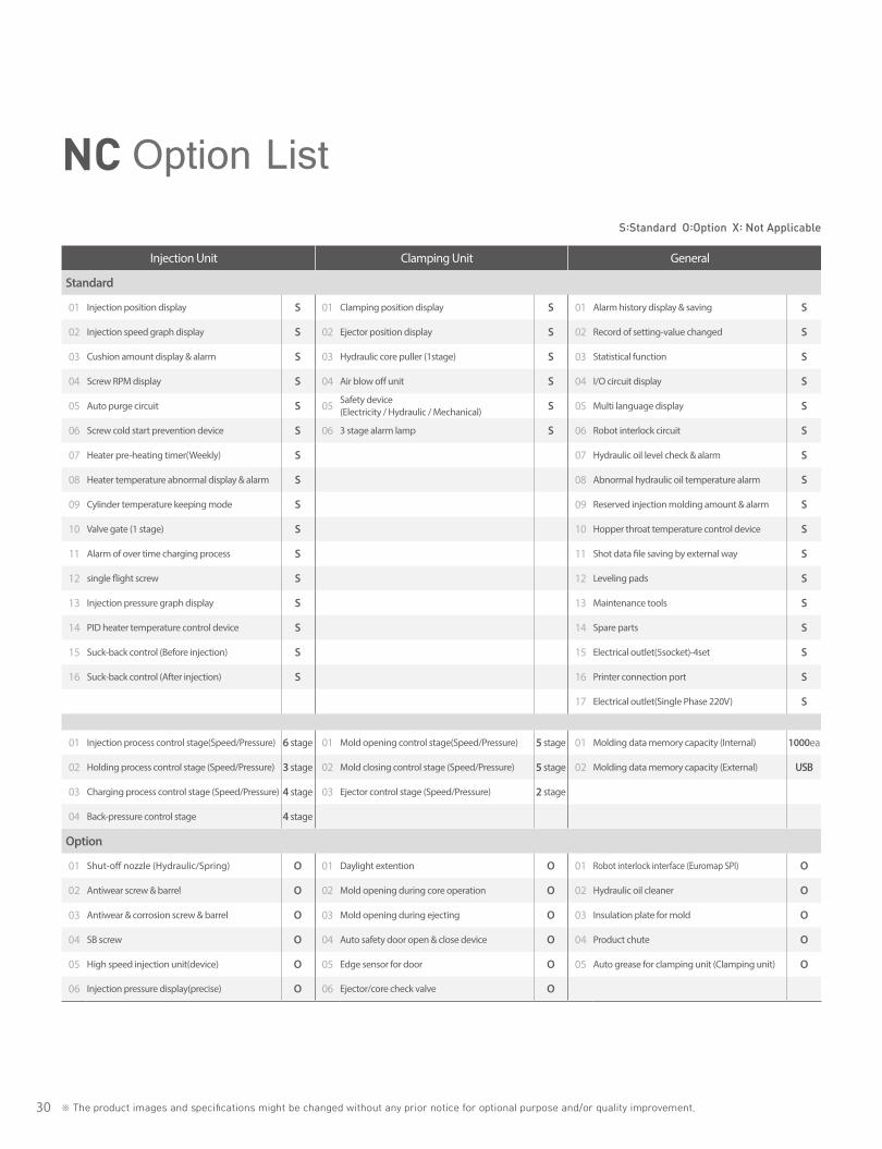
30 ※ The product images and specifications might be changed without any prior notice for optional purpose and/or quality improvement.
NC Option ListS:Standard O:Option X: Not Applicable
Injection Unit Clamping Unit General
Standard
01 Injection position display S 01 Clamping position display S 01 Alarm history display & saving S
02 Injection speed graph display S 02 Ejector position display S 02 Record of setting-value changed S
03 Cushion amount display & alarm S 03 Hydraulic core puller (1stage) S 03 Statistical function S
04 Screw RPM display S 04 Air blow off unit S 04 I/O circuit display S
05 Auto purge circuit S 05 Safety device (Electricity / Hydraulic / Mechanical) S 05 Multi language display S
06 Screw cold start prevention device S 06 3 stage alarm lamp S 06 Robot interlock circuit S
07 Heater pre-heating timer(Weekly) S 07 Hydraulic oil level check & alarm S
08 Heater temperature abnormal display & alarm S 08 Abnormal hydraulic oil temperature alarm S
09 Cylinder temperature keeping mode S 09 Reserved injection molding amount & alarm S
10 Valve gate (1 stage) S 10 Hopper throat temperature control device S
11 Alarm of over time charging process S 11 Shot data file saving by external way S
12 single flight screw S 12 Leveling pads S
13 Injection pressure graph display S 13 Maintenance tools S
14 PID heater temperature control device S 14 Spare parts S
15 Suck-back control (Before injection) S 15 Electrical outlet(5socket)-4set S
16 Suck-back control (After injection) S 16 Printer connection port S
17 Electrical outlet(Single Phase 220V) S
01 Injection process control stage(Speed/Pressure) 6 stage 01 Mold opening control stage(Speed/Pressure) 5 stage 01 Molding data memory capacity (Internal) 1000ea
02 Holding process control stage (Speed/Pressure) 3 stage 02 Mold closing control stage (Speed/Pressure) 5 stage 02 Molding data memory capacity (External) USB
03 Charging process control stage (Speed/Pressure) 4 stage 03 Ejector control stage (Speed/Pressure) 2 stage
04 Back-pressure control stage 4 stage
Option
01 Shut-off nozzle (Hydraulic/Spring) O 01 Daylight extention O 01 Robot interlock interface (Euromap SPI) O
02 Antiwear screw & barrel O 02 Mold opening during core operation O 02 Hydraulic oil cleaner O
03 Antiwear & corrosion screw & barrel O 03 Mold opening during ejecting O 03 Insulation plate for mold O
04 SB screw O 04 Auto safety door open & close device O 04 Product chute O
05 High speed injection unit(device) O 05 Edge sensor for door O 05 Auto grease for clamping unit (Clamping unit) O
06 Injection pressure display(precise) O 06 Ejector/core check valve O

31
WOOJINPLAIMM

2/1.2018Printed in KOREA.WOOJIN
CopyRightⓒ2018, WOOJIN PLAIMM Co.,Ltd
The brochure is protected by copyright.Any utilization, which is not expressly permitted under copyright legislation,requires the previous approval of WOOJIN PLAIMM
The product images and specifications might be changed without any prior notice for optional purpose and/or quality improvement.


![perTormance curves an CR 10 CR 10 [kPa] [m] d tech nical ... 10.pdf · perTormance curves an CR 10 CR 10 [kPa] [m] d tech nical data 1.5 CR, CRI, CRN CR 10 50 Hz ISO 9906:1999 Annex](https://img.pdfslide.us/doc/110x75/5e3d2191ebefda7c2e01de5e/pertormance-curves-an-cr-10-cr-10-kpa-m-d-tech-nical-10pdf-pertormance.jpg)