Embed Size (px)
Citation preview
Zip HydroTapFiltered boiling and chilled water for kitchens and tea rooms
73075 Zip HydroTap ABC10/30FXC73097 Zip HydroTap ABC30/30FXC
73077 Zip HydroTap ABC10/30FC73094 Zip HydroTap ABC30/30FC
73088 Zip HydroTap ABA10FXC73103 Zip HydroTap ABA30FXC
73091 Zip HydroTap ABA10FC73100 Zip HydroTap ABA30FC
73109 Zip HydroTap ABB10FXC73115 Zip HydroTap ABB30FXC
73106 Zip HydroTap ABB10FC73112 Zip HydroTap ABB30FC
73107 Zip HydroTap B1OC73108 Zip HydroTap B3OC
Installation Instructions and Operating Procedures
®

Page 2 of 20 Zip Hydrotap Installation and Operating Instructions - 82871 - July 2003
Zip Hydrotap Installation and Operating Instructions - 82871 - July 2003 Page 3 of 20
Contents
Read These Warnings First . . . . . . . . . . . . . . . . . . . . . . . . . .4
Models covered by these instructions . . . . . . . . . . . . . . . . . .5
Installation Requirements . . . . . . . . . . . . . . . . . . . . . . . . . . .5
Special tools required . . . . . . . . . . . . . . . . . . . . . . . . . . . . . .6
Installation procedure . . . . . . . . . . . . . . . . . . . . . . . . . . . . . .6
Step A - Installing the tap (all models) . . . . . . . . . . . .6
Step B - Installing the undersink unit (all models) . . .7
Step C - Connecting the tap . . . . . . . . . . . . . . . . . . .7
Installation with Tap Font . . . . . . . . . . . . . . . . . . . . . . . . . . . .8
Tap Font Mounting Template . . . . . . . . . . . . . . . . . . . . . . . . .a - d
Step C - Connecting the Tap Continued . . . . . . . . . . .13
Step D - Connecting the Water Supply (all models) . .14
Step E - Testing and commissioning . . . . . . . . . . . . .14
Solving general problems . . . . . . . . . . . . . . . . . . . . .15
Operating the Tap . . . . . . . . . . . . . . . . . . . . . . . . . . . . . . . . .16
Cleaning . . . . . . . . . . . . . . . . . . . . . . . . . . . . . . . . . . . . . . . .17
Replacing the Filter . . . . . . . . . . . . . . . . . . . . . . . . . . . . . . . .17
Setting the Energy Saver Timer . . . . . . . . . . . . . . . . . . . . . . .18
Setting Correct Time . . . . . . . . . . . . . . . . . . . . . . . . .18
Programming Power ON & OFF . . . . . . . . . . . . . . . . .18
Warranty Information . . . . . . . . . . . . . . . . . . . . . . . . . . . . . . .20
Page 4 of 20 Zip Hydrotap Installation and Operating Instructions - 82871 - July 2003
Read These Warnings First
Safety
Do not allow young children, handicapped or infirm persons, to use the ZipHydroTap without supervision
Refrigerant
The Zip HydroTap Chilling unit contains 134A refrigerant under pressure. Nopart of the unit should be exposed to a naked flame. Maintenance ofrefrigeration unit must be carried out by an accredited service provider orqualified refrigeration mechanic.
Qualifications
If any power cord or plug is damaged it must be repaired only by aqualified technician.
To avoid hazards, all installation procedures must be carried out by asuitably qualified tradesperson.
Venting
Sometimes steam and/or boiling water may discharge through the vent atthe rear of the tap shank. If the tap is not installed on a sink, the pipe tothis outlet must be disconnected and plumbed away to a safe locationaccording to local plumbing bylaws and regulations.
Lifting
Take care when lifting the Zip HydroTap undersink unit. Some units mayexceed safe lifting limits. Do not lift without assistance. The weights of theunits are given in the table under Installation Requirements (page 5).
Airflow
Proper air circulation must be provided. The system will operatesatisfactorily only if the recommended air gaps are provided. If this is notpossible, ventilation slots must be cut into the top AND bottom of thecupboard door. Make sure that the ventilation grilles of the undersink unitare not obstructed.
Altitude
At altitudes over 500 metres above sea level, the thermostat temperaturemay require adjustment. Contact your Zip Service Provider.
Filter
For models ABC, ABA and ABB only:
The Zip HydroTap filter timer is preset to nine months to provide trouble-free flow and operation in most installations. Local water quality conditionsmay require an alteration to this time. In areas where the water has a highconcentration of sediment, the preset time may be shortened to avoid poorflow, taste or odour situations. In areas where the water quality is aboveaverage, lengthening the preset time may be desirable, but not essential. Ifany of these changes are needed, contact your Zip Service Provider.
Zip Hydrotap Installation and Operating Instructions - 82871 - July 2003 Page 5 of 20
# Section Heading# Section HeadingThese Installation Instructions cover the entire Zip HydroTap range. Use thechart on the left to identify the model you are using:
Model:ABC = Filtered, boiling and chilled, timerABA = Filtered, boiling and ambientABB = Filtered, boiling onlyB = Boiling only (unfiltered)Boiling Water Capacity:10 = 10 cups 30 = 30 cupsChilled Water Capacity: (ABC only)30 = 30 cupsFiltration: (ABA, ABB and ABC only)FX = Sub micron filter
Models covered by these instructions
Before installing ensure that the following have been provided at theinstallation site:
• Sufficient space in the cupboard to install the undersink unit inaccordance with these Installation Instructions. A table of dimensions isgiven below.
• A water supply connection with isolating valve inside the cupboardwithin reach of the 750 mm flexible connection and positioned so thatthe connection point and the stop cock will not be obstructed when theundersink unit is installed.
• A water supply which can deliver 2 litres per minute flow rate atminimum of 150 kPa flow (dynamic) pressure.
• Power supply 220-240 Volt AC, for connection to the heater via a 10 ampG.P.O.
• Cold water supply with a minimum working pressure of 150 kPa and amaximum working pressure of 1,000 kPa connected via an isolationvalve.
Important:
Do not proceed with the installation if these requirements are not met.
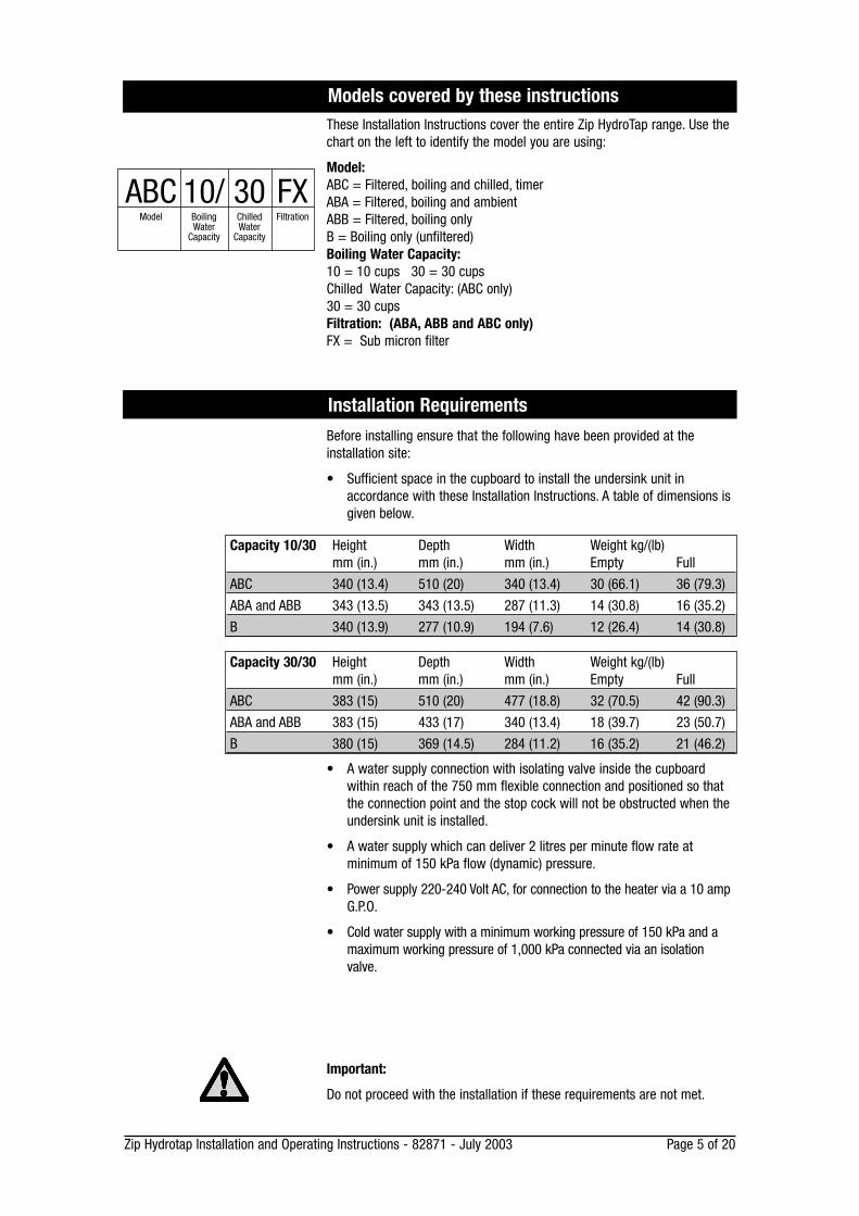
Capacity 10/30 Height Depth Width Weight kg/(lb)mm (in.) mm (in.) mm (in.) Empty Full
ABC 340 (13.4) 510 (20) 340 (13.4) 30 (66.1) 36 (79.3)
ABA and ABB 343 (13.5) 343 (13.5) 287 (11.3) 14 (30.8) 16 (35.2)
B 340 (13.9) 277 (10.9) 194 (7.6) 12 (26.4) 14 (30.8)
Capacity 30/30 Height Depth Width Weight kg/(lb)mm (in.) mm (in.) mm (in.) Empty Full
ABC 383 (15) 510 (20) 477 (18.8) 32 (70.5) 42 (90.3)
ABA and ABB 383 (15) 433 (17) 340 (13.4) 18 (39.7) 23 (50.7)
B 380 (15) 369 (14.5) 284 (11.2) 16 (35.2) 21 (46.2)
Installation Requirements
ABCModel
10/BoilingWater
Capacity
30ChilledWater
Capacity
FXFiltration
Page 6 of 20 Zip Hydrotap Installation and Operating Instructions - 82871 - July 2003
In addition to normal tools, the following will be required:
• 13.5 mm diameter sheet metal hole punch
• 35 mm diameter sheet metal hole punch.
Special tools required
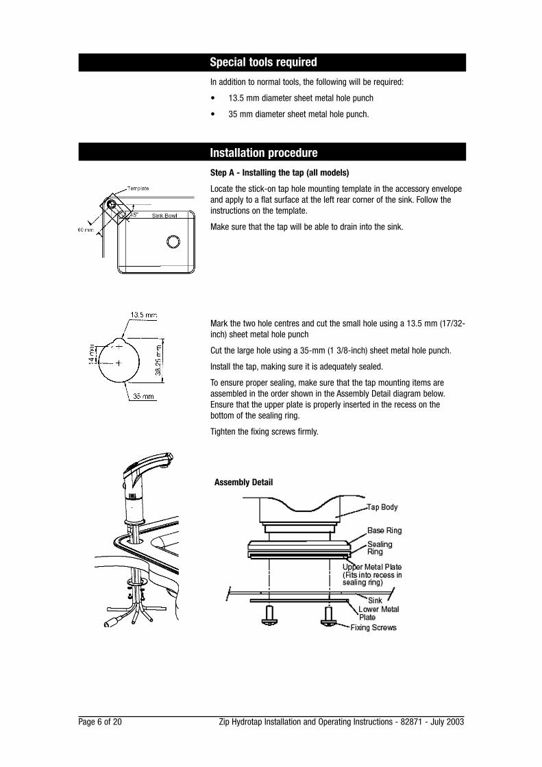
Step A - Installing the tap (all models)
Locate the stick-on tap hole mounting template in the accessory envelopeand apply to a flat surface at the left rear corner of the sink. Follow theinstructions on the template.
Make sure that the tap will be able to drain into the sink.
Mark the two hole centres and cut the small hole using a 13.5 mm (17/32-inch) sheet metal hole punch
Cut the large hole using a 35-mm (1 3/8-inch) sheet metal hole punch.
Install the tap, making sure it is adequately sealed.
To ensure proper sealing, make sure that the tap mounting items areassembled in the order shown in the Assembly Detail diagram below.Ensure that the upper plate is properly inserted in the recess on thebottom of the sealing ring.
Tighten the fixing screws firmly.
Installation procedure
Assembly Detail
Zip Hydrotap Installation and Operating Instructions - 82871 - July 2003 Page 7 of 20
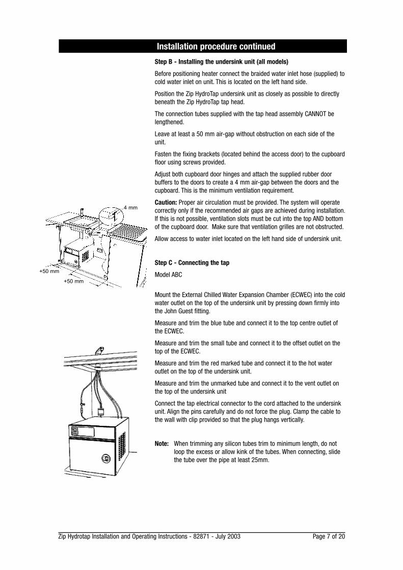
Step B - Installing the undersink unit (all models)
Before positioning heater connect the braided water inlet hose (supplied) tocold water inlet on unit. This is located on the left hand side.
Position the Zip HydroTap undersink unit as closely as possible to directlybeneath the Zip HydroTap tap head.
The connection tubes supplied with the tap head assembly CANNOT belengthened.
Leave at least a 50 mm air-gap without obstruction on each side of theunit.
Fasten the fixing brackets (located behind the access door) to the cupboardfloor using screws provided.
Adjust both cupboard door hinges and attach the supplied rubber doorbuffers to the doors to create a 4 mm air-gap between the doors and thecupboard. This is the minimum ventilation requirement.
Caution: Proper air circulation must be provided. The system will operatecorrectly only if the recommended air gaps are achieved during installation.If this is not possible, ventilation slots must be cut into the top AND bottomof the cupboard door. Make sure that ventilation grilles are not obstructed.
Allow access to water inlet located on the left hand side of undersink unit.
Step C - Connecting the tap
Model ABC
Mount the External Chilled Water Expansion Chamber (ECWEC) into the coldwater outlet on the top of the undersink unit by pressing down firmly intothe John Guest fitting.
Measure and trim the blue tube and connect it to the top centre outlet ofthe ECWEC.
Measure and trim the small tube and connect it to the offset outlet on thetop of the ECWEC.
Measure and trim the red marked tube and connect it to the hot wateroutlet on the top of the undersink unit.
Measure and trim the unmarked tube and connect it to the vent outlet onthe top of the undersink unit
Connect the tap electrical connector to the cord attached to the undersinkunit. Align the pins carefully and do not force the plug. Clamp the cable tothe wall with clip provided so that the plug hangs vertically.
Note: When trimming any silicon tubes trim to minimum length, do notloop the excess or allow kink of the tubes. When connecting, slidethe tube over the pipe at least 25mm.
Installation procedure continued
4 mm
+50 mm
+50 mm
Page 8 of 20 Zip Hydrotap Installation and Operating Instructions - 82871 - July 2003
Installation with Tap Font
Features
The sump built into the Tap-Font drains away to any nearby waste.
Tap - Font also elevates tap outlet to provide 210 mm clearance for pots.
Positioning
Position Tap-Font as close as possible to directly above under-sink unit.
Never extend either the cable or tubing attached to the head assembly.
If possible position tray on bench so the tap is to the rear, then rotate base 45degrees anti-clockwise.
Drilling
Use paper template to drill 57 mm hole, 45 mm hole and 4 screw holes.
For timber bench, drill 3 mm screw holes for timber screws provided.
For granite or similar, drill 6 mm holes for stainless screws provided.
Assembling
Fix clamp plate to bench top using 4 "timber" or "stainless" screws provided.
Remove silicon vent tube from base of tap assembly as shown in diagram.
Pass electrical cable, then tubes, from tap base through pedestal as shown.
Check cable and tubes to ensure all are free, none are twisted or kinked.
Fix the tap head assembly to pedestal using 3 pedestal screws.
Apply sealant to thread on brass tube supplied, screw into pedestal base.
Attach disconnected silicon vent tube to brass vent tube as shown in photo.
Apply a light bead of sealant to the underside edge of the sump tray.
Position the tray so the sump drain outlet lines up with the fixing plate hole.
Swivel tray so pedestal is positioned above largest hole in bench.
Pass all cables and tubes from pedestal through largest hole in bench.
Fit clamp spacer and lock nut on to drain bush and tighten securely.
Clean off any sealant squeezed out around sump tray during clamping.
Connecting
Install the waste clamp in an accessible position on the "sink side" of draintrap and as high as possible above the trap water line.
The waste clamp must never be installed on the "drain side" of draintrap.
To drill access hole into trap, remove nut and olive from clamp fitting andselect drill bit to fit inside diameter of the clamp fitting hole.
Fasten clamp to drain pipe and drill access hole through hole in clamp.
Apply sealant to thread on brass tube supplied and fasten tube to clamp withnut and olive, referred to above.
Apply sealant to similar brass tube and fit to drain bush on sump.
Connect tube on clamp to tube on sump using flexible tubing provided.
Ensure flexible tube has a continuous fall from sump to clamp.
Remove protective coating from stainless steel, wipe clean and fit removabledrip plate. Fit remaining tubes and cable as shown on page 7.
Inserting screw through pedestalto underside of tap.
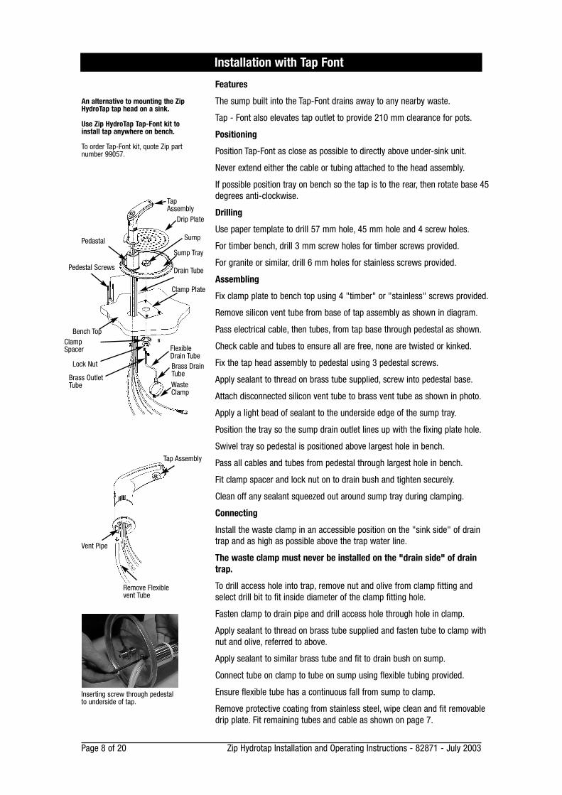
An alternative to mounting the ZipHydroTap tap head on a sink.
Use Zip HydroTap Tap-Font kit toinstall tap anywhere on bench.
To order Tap-Font kit, quote Zip partnumber 99057.
Tap Assembly
Remove Flexiblevent Tube
Vent Pipe
Drip Plate
Brass OutletTube
ClampSpacer
TapAssembly
WasteClamp
Brass DrainTube
Clamp Plate
Bench Top
FlexibleDrain Tube
Lock Nut
Drain Tube
Sump
Sump Tray
Pedestal Screws
Pedastal
Zip Hydrotap Installation and Operating Instructions - 82871 - July 2003 Page a
Detach this paper template and use itto position your Zip Hydrotap Tap-Fonton your kitchen bench.
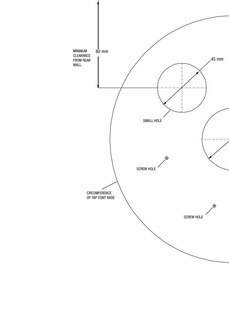
80 mm
45 mm
MINIMUMCLEARANCEFROM REARWALL.
CIRCUMFERENCEOF TAP-FONT BASE
SMALL HOLE
SCREW HOLE
SCREW HOLE
45 mm
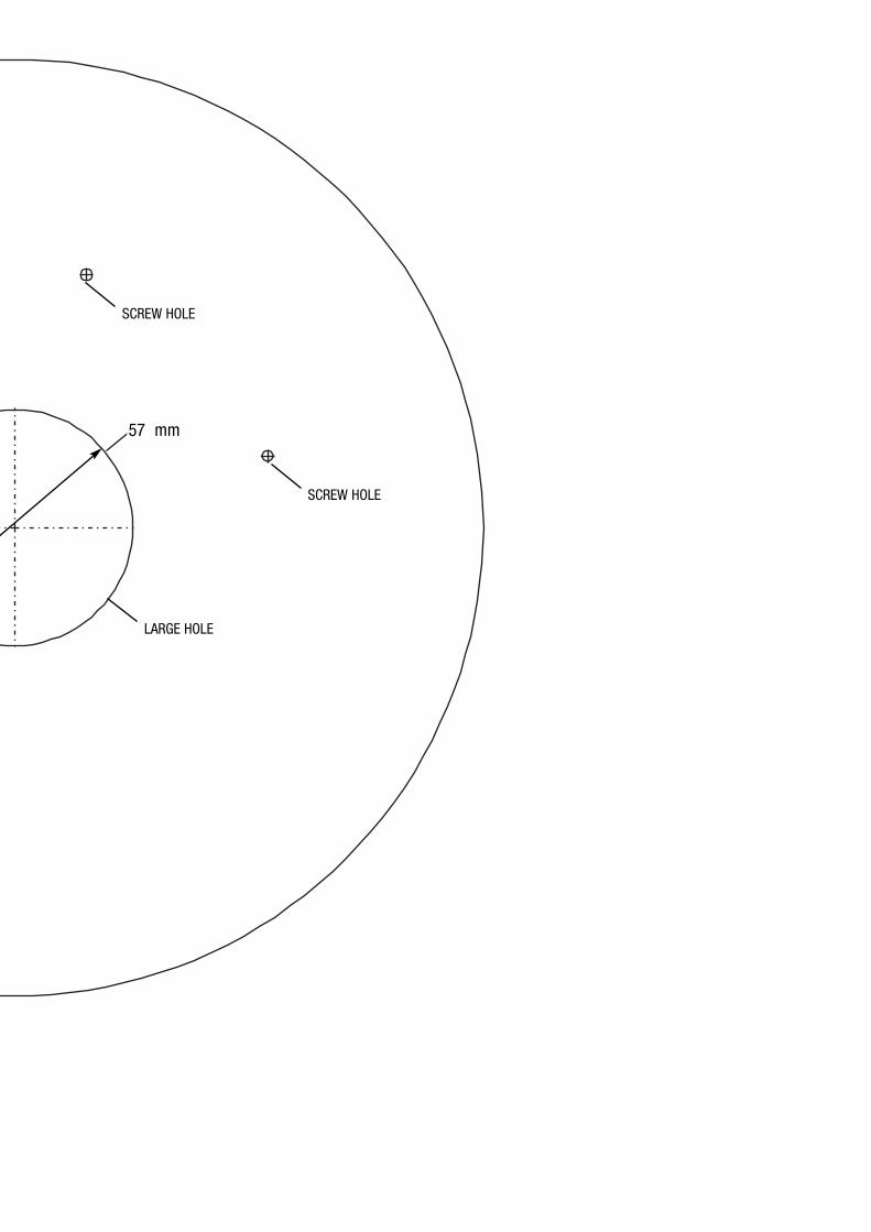
57 mm
SCREW HOLE
SCREW HOLE
LARGE HOLE
Page d Zip Hydrotap Installation and Operating Instructions - 82871 - July 2003
Detach this paper template and use itto position your Zip Hydrotap Tap-Fonton your kitchen bench.
Zip Hydrotap Installation and Operating Instructions - 82871 - July 2003 Page 13 of 20
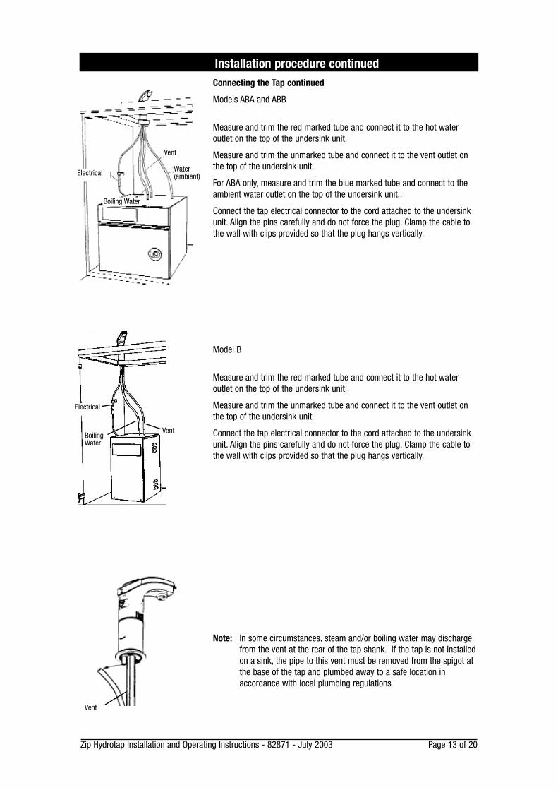
Connecting the Tap continued
Models ABA and ABB
Measure and trim the red marked tube and connect it to the hot wateroutlet on the top of the undersink unit.
Measure and trim the unmarked tube and connect it to the vent outlet onthe top of the undersink unit.
For ABA only, measure and trim the blue marked tube and connect to theambient water outlet on the top of the undersink unit..
Connect the tap electrical connector to the cord attached to the undersinkunit. Align the pins carefully and do not force the plug. Clamp the cable tothe wall with clips provided so that the plug hangs vertically.
Model B
Measure and trim the red marked tube and connect it to the hot wateroutlet on the top of the undersink unit.
Measure and trim the unmarked tube and connect it to the vent outlet onthe top of the undersink unit.
Connect the tap electrical connector to the cord attached to the undersinkunit. Align the pins carefully and do not force the plug. Clamp the cable tothe wall with clips provided so that the plug hangs vertically.
Note: In some circumstances, steam and/or boiling water may dischargefrom the vent at the rear of the tap shank. If the tap is not installedon a sink, the pipe to this vent must be removed from the spigot atthe base of the tap and plumbed away to a safe location inaccordance with local plumbing regulations
Installation procedure continued
Electrical
Vent
Water(ambient)
Boiling Water
Electrical
BoilingWater
Vent
Vent
Page 14 of 20 Zip Hydrotap Installation and Operating Instructions - 82871 - July 2003
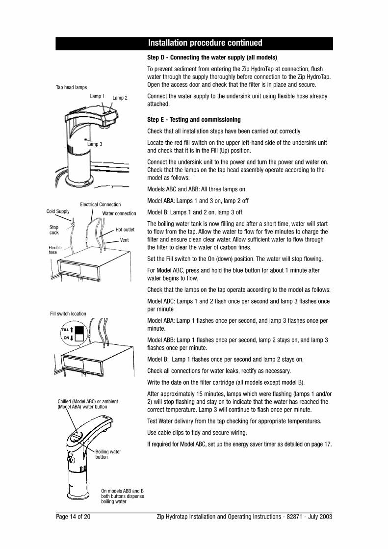
Step D - Connecting the water supply (all models)
To prevent sediment from entering the Zip HydroTap at connection, flushwater through the supply thoroughly before connection to the Zip HydroTap.Open the access door and check that the filter is in place and secure.
Connect the water supply to the undersink unit using flexible hose alreadyattached.
Step E - Testing and commissioning
Check that all installation steps have been carried out correctly
Locate the red fill switch on the upper left-hand side of the undersink unitand check that it is in the Fill (Up) position.
Connect the undersink unit to the power and turn the power and water on.Check that the lamps on the tap head assembly operate according to themodel as follows:
Models ABC and ABB: All three lamps on
Model ABA: Lamps 1 and 3 on, lamp 2 off
Model B: Lamps 1 and 2 on, lamp 3 off
The boiling water tank is now filling and after a short time, water will startto flow from the tap. Allow the water to flow for five minutes to charge thefilter and ensure clean clear water. Allow sufficient water to flow throughthe filter to clear the water of carbon fines.
Set the Fill switch to the On (down) position. The water will stop flowing.
For Model ABC, press and hold the blue button for about 1 minute afterwater begins to flow.
Check that the lamps on the tap operate according to the model as follows:
Model ABC: Lamps 1 and 2 flash once per second and lamp 3 flashes onceper minute
Model ABA: Lamp 1 flashes once per second, and lamp 3 flashes once perminute.
Model ABB: Lamp 1 flashes once per second, lamp 2 stays on, and lamp 3flashes once per minute.
Model B: Lamp 1 flashes once per second and lamp 2 stays on.
Check all connections for water leaks, rectify as necessary.
Write the date on the filter cartridge (all models except model B).
After approximately 15 minutes, lamps which were flashing (lamps 1 and/or2) will stop flashing and stay on to indicate that the water has reached thecorrect temperature. Lamp 3 will continue to flash once per minute.
Test Water delivery from the tap checking for appropriate temperatures.
Use cable clips to tidy and secure wiring.
If required for Model ABC, set up the energy saver timer as detailed on page 17.
Installation procedure continued
Water connection
Stopcock
Flexiblehose
Fill switch location
Tap head lamps
Lamp 3
Lamp 2Lamp 1
Chilled (Model ABC) or ambient (Model ABA) water button
Boiling waterbutton
On models ABB and Bboth buttons dispenseboiling water
Electrical ConnectionCold Supply
Hot outlet
Vent
Page 15 of 20 Zip Hydrotap Installation and Operating Instructions - 82871 - July 2003
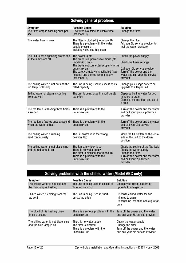
Symptom Possible Cause SolutionThe filter lamp is flashing once per The filter is outside its usable time Change the filtersec (not model B)
The water flow is slow The filter is blocked. (not model B) Change the filterThere is a problem with the water Ask you Zip service provider to supply pressure test the water pressureIsolating valve not fully open
The unit is not dispensing water and The power is off Check the power supplyall the lamps are off The timer is in power save mode (off)
(model ABC only) Check the timer settingsThe tap is not connected properly to theundersink unit Call your Zip service providerThe safety shutdown is activated (tray Turn off the power and the flooded) and the red lamp is faulty water and call your Zip service(not model B) provider
The boiling water is not hot and the The unit is being used in excess of its Change your usage pattern orred lamp is flashing rated capacity upgrade to a larger unit
Boiling water or steam is coming The unit is being used in short bursts Dispense boiling water for two from tap vent too often minutes to drain.
Dispense no less than one up ata time
The red lamp is flashing three times There is a problem with the Turn off the power and the water a second undersink unit and call your your Zip Service
provider
The red lamp flashes once a second There is a problem with the Turn off the power and the waterwhen the water is hot undersink unit and call your Zip service
provider
The boiling water is running The Fill switch is in the wrong Move the Fill switch on the left ohard continuously position (Up) side of the unit to the down
position
The boiling water is not dispensing The Tap safety lock is set Check the setting of the Tap lockand the red lamp is on There is no water supply Check the water supply
The filter is blocked. (not model B) Change the filterThere is a problem with the Turn off the power and the waterundersink unit and call your Zip service
provider
Solving general problems
SymptomThe chilled water is not cold andthe blue lamp is flashing
Chilled water is coming from thetap vent
The blue light is flashing threetimes a second
The chilled water is not dispensingand the blue lamp is on
Possible CauseThe unit is being used in excess ofits rated capacity
The unit is being used in shortbursts too often
There is a serious problem with theundersink unit
There is no water supplyThe filter is blockedThere is a problem with the undersink unit
SolutionChange your usage pattern orupgrade to a larger unit
Dispense chilled water for twominutes to drain.Dispense no less than one cup at attime
Turn off the power and the waterand call your Zip service provider
Check the water supplyChange the filterTurn off the power and the waterand call your Zip service Provider
Solving problems with the chilled water (Model ABC only)
Page 16 of 20 Zip Hydrotap Installation and Operating Instructions - 82871 - July 2003
Operating the Tap
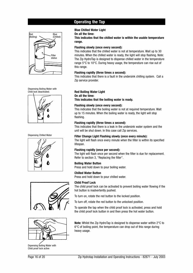
Blue Chilled Water LightOn all the time: This indicates that the chilled water is within the usable temperaturerange.
Flashing slowly (once every second): This indicates that the chilled water is not at temperature. Wait up to 30minutes. When the chilled water is ready, the light will stop flashing. Note:The Zip HydroTap is designed to dispense chilled water in the temperaturerange 5°C to 10°C. During heavy usage, the temperature can rise out ofthis range.
Flashing rapidly (three times a second): This indicates that there is a fault in the undersink chilling system. Call aZip service provider.
Red Boiling Water Light On all the time: This indicates that the boiling water is ready.
Flashing slowly (once every second): This indicates that the boiling water is not at required temperature. Waitup to 15 minutes. When the boiling water is ready, the light will stopflashing.
Flashing rapidly (three times a second): This indicates that there is a leak in the undersink water system and theunit will be shut down. In this case call Zip services.
Filter Change Light Flashing slowly (once every minute): The light will flash once every minute when the filter is within its specifiedlifespan.
Flashing rapidly (once per second): The light will flash once per second when the filter is due for replacement.Refer to section 3, "Replacing the filter".
Boiling Water ButtonPress and hold down to pour boiling water.
Chilled Water ButtonPress and hold down to pour chilled water.
Child Proof LockThe child proof lock can be activated to prevent boiling water flowing if thehot button is inadvertently pushed.
To turn on, rotate the red button to the locked position.
To turn off, rotate the red button to the unlocked position.
To operate the tap when the child proof lock is activated, press and holdthe child proof lock button in and then press the hot water button.
Note: Whilst the Zip HydroTap is designed to dispense water within 2°C to6°C of boiling point, the temperature can drop out of this range duringheavy usage.
Dispensing Boiling Water withChild lock deactivated.
Dspensing Boiling Water withChild proof lock active
Red(Boiling)
Blue(Chilled)
Filterstatus
Dispensing Chilled Water
Zip Hydrotap Installation and Operating Instructions - 82871 - July 2003 Page 17 of 20
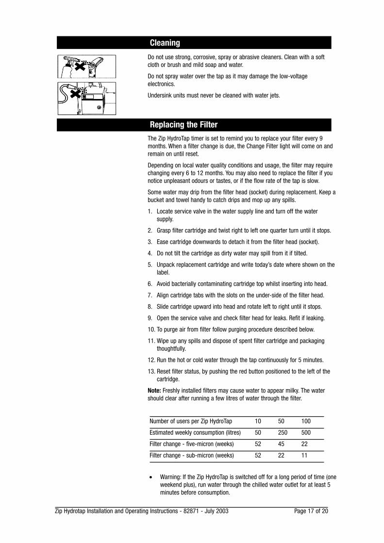
Cleaning
Do not use strong, corrosive, spray or abrasive cleaners. Clean with a softcloth or brush and mild soap and water.
Do not spray water over the tap as it may damage the low-voltage electronics.
Undersink units must never be cleaned with water jets.
The Zip HydroTap timer is set to remind you to replace your filter every 9months. When a filter change is due, the Change Filter light will come on andremain on until reset.
Depending on local water quality conditions and usage, the filter may requirechanging every 6 to 12 months. You may also need to replace the filter if younotice unpleasant odours or tastes, or if the flow rate of the tap is slow.
Some water may drip from the filter head (socket) during replacement. Keep abucket and towel handy to catch drips and mop up any spills.
1. Locate service valve in the water supply line and turn off the watersupply.
2. Grasp filter cartridge and twist right to left one quarter turn until it stops.
3. Ease cartridge downwards to detach it from the filter head (socket).
4. Do not tilt the cartridge as dirty water may spill from it if tilted.
5. Unpack replacement cartridge and write today’s date where shown on thelabel.
6. Avoid bacterially contaminating cartridge top whilst inserting into head.
7. Align cartridge tabs with the slots on the under-side of the filter head.
8. Slide cartridge upward into head and rotate left to right until it stops.
9. Open the service valve and check filter head for leaks. Refit if leaking.
10. To purge air from filter follow purging procedure described below.
11. Wipe up any spills and dispose of spent filter cartridge and packagingthoughtfully.
12. Run the hot or cold water through the tap continuously for 5 minutes.
13. Reset filter status, by pushing the red button positioned to the left of thecartridge.
Note: Freshly installed filters may cause water to appear milky. The watershould clear after running a few litres of water through the filter.
Replacing the Filter
• Warning: If the Zip HydroTap is switched off for a long period of time (oneweekend plus), run water through the chilled water outlet for at least 5minutes before consumption.
Number of users per Zip HydroTap 10 50 100
Estimated weekly consumption (litres) 50 250 500
Filter change - five-micron (weeks) 52 45 22
Filter change - sub-micron (weeks) 52 22 11
Page 18 of 20 Zip Hydrotap Installation and Operating Instructions - 82871 - July 2003
# Section Heading
If you do NOT wish to programme the timer to turn the Zip HydroTap on andoff daily, you may ignore the following instructions.
The Zip HydroTap will operate continuously if you do not programme thetimer at all.
If you do wish to programme the timer to turn the Zip HydroTap on and offdaily, first set the timer to the correct time, then follow the instructions setout below. You can programme the timer to turn the Zip HydroTap on andoff up to 3 times daily.
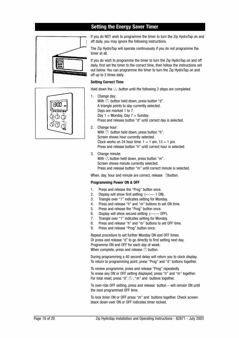
Setting Correct Time
Hold down the button until the following 3 steps are completed.
1. Change day:With button held down, press button “d”.A triangle points to day currently selected.Days are marked 1 to 7.Day 1 = Monday, Day 7 = Sunday.Press and release button “d” until correct day is selected.
2. Change hour:With button held down, press button “h”.Screen shows hour currently selected.Clock works on 24 hour time: 1 = 1 am, 13 = 1 pm.Press and release button “h” until correct hour is selected.
3. Change minute:With button held down, press button “m”.Screen shows minute currently selected.Press and release button “m” until correct minute is selected.
When, day, hour and minute are correct, release button.
Programming Power ON & OFF
1. Press and release the “Prog” button once.2. Display will show first setting: (—:— 1 ON).3. Triangle over “1” indicates setting for Monday.4. Press and release “h” and “m” buttons to set ON time.5. Press and release the “Prog” button once.6. Display will show second setting: (—:— OFF).7. Triangle over “1” indicates setting for Monday.8. Press and release “h” and “m” buttons to set OFF time.9. Press and release “Prog” button once.
Repeat procedure to set further Monday ON and OFF times.Or press and release “d” to go directly to first setting next day.Programme ON and OFF for each day of week.When complete, press and release button.
During programming a 40 second delay will return you to clock display.To return to programming point, press “Prog” and “d” buttons together.
To review programme, press and release “Prog” repeatedly.To erase any ON or OFF setting displayed, press “h” and “m” together.For total reset, press “d”, , “m” and buttons together.
To over-ride OFF setting, press and release button – will remain ON untilthe next programmed OFF time.
To lock timer ON or OFF press “m” and buttons together. Check screen:black down over ON or OFF indicates timer locked.
Setting the Energy Saver Timer
prog.
mhd

Zip Hydrotap Installation and Operating Instructions - 82871 - July 2003 Page 19 of 20
Page 20 of 20 Zip Hydrotap Installation and Operating Instructions - 82871 - July 2003
WarrantyThe Zip appliance you have chosen is precision-built from the finestmaterials available and should give many years of trouble free service.
Certain warranties may be implied by law into your contract with Zip. Thewarranty provided below is additional to these implied warranties andnothing set out below shall limit your statutory rights or rights at law.
Zip Heaters (Aust) Pty Ltd warrants that, should any part fail within 12calendar months of installation, that part will be repaired or replaced freeof charge by Zip or its Distributor or Service Provider, except as set outbelow, provided the appliance is installed and used strictly in accordancewith the instructions supplied, and that failure is not due to accident,misuse, abuse, unsuitable water conditions, or to any alteration,modification or repair by any party not expressly nominated by Zip.
No costs are payable by the customer other than any mileage or travelling-time charges incurred by a Zip Service Provider or the cost of removal,cartage and re-installation of any component of the appliance if it needs tobe returned for repair to Zip or its Distributor.
This warranty does not cover damage resulting from non-operation of theappliance or consequential damage to any other goods, furnishings orproperty.
No warranty applies to the life of any filtration cartridge installed with theappliance as cartridge life may vary according to water quality and the rateof water consumption.
Zip does not exclude, restrict or modify any liability that cannot beexcluded, restricted or modified or which cannot, except to a limited extent,be excluded, restricted or modified as between the owner or user and Zipunder the laws applicable.
Furthermore, this warranty does not displace any statutory warranty, but, tothe extent to which Zip is entitled to do so, the liability of Zip under anystatutory warranty will be limited at Zip's option to the replacement of theappliance or supply of equivalent appliance, the payment of the cost ofreplacing the appliance or acquiring an equivalent appliance, or thepayment of the cost of having the appliance repaired or the repair of theappliance.
Registering Your Purchase
Registering your Zip installation on the Zip website may help to establishdate of installation should it become necessary to service the applianceunder terms of the Zip warranty. To register your installation go towww.zipheaters.com and look under the heading "Warranty".
The standard cup referred to in this publication is 167 ml (6 fl oz).The standard glass is 200 ml (7 fl oz).The terms "Zip" and "HydroTap" are registered trade marks of Zip Heaters (Aust) Pty Ltd.Zip products described in this publication are manufactured under one or more of the followingpatents: AU675601, AU637412, AU635979, GB0422305, GB2065848, US4354049, US5103859,and US5099825. Other patents are in force and patent applications are pending.
Head Office
Zip Heaters (Aust) Pty. Ltd.67 Allingham StreetCondell Park NSW 2200 Postal: Locked Bag 80Bankstown 1885 Australia
Website: www.zipheaters.comFacsimile: (02) 9796 3858Telephone: (02) 9796 3100Free Call: 1 800 638 633


![Background – Operators (1D) · Background (1D) Operators 4 Young Won Lim 3/28/18 zip function zip :: [a] -> [b] -> [(a,b)] zip (a:as) (b:bs) = (a,b) : zip as bs zip _ _ = [] Prelude>](https://img.pdfslide.us/doc/110x75/5f7d53a36176442cad227c24/background-a-operators-1d-background-1d-operators-4-young-won-lim-32818.jpg)


![TAP TAP Basics (Preparing for Success in a TAP School) [PSTS]](https://img.pdfslide.us/doc/110x75/56649eb25503460f94bb9499/tap-tap-basics-preparing-for-success-in-a-tap-school-psts.jpg)