Embed Size (px)
Citation preview

International Journal Of Scientific & Engineering Research, Volume 4, Issue 5, May 2013
ISSN 2229-5518
1
Z – Source Inverter Fed Induction
MotorSelva santhose kumar R, Poonkodi V, Seethalakshmi M, Yamuna A
Abstract- In this paper modelling and simulation of control strategy for Z-source inverter is presented. The performance
of single-phase induction motor is studied with the control of single phase Z-source inverter using Simple boost controller. This
controller senses the motor speed feedback signal and consequently provides the pulse width modulated (PWM) signal that
sets the gate voltage of the inverter, which in turn provides the required voltage for the desired speed. The proposed drive
system is simulated using MATLAB/Simulink. The simulation results were compared with the experimental results.
Index Terms- Induction motor, MATLAB, Pulse width modulation technique, Shoot through state, Simple boost control,
Switching states, Z-source inverter.
—————————— ——————————
1 INTRODUCTION:
Induction motors have many advantages compared to
DC motors and synchronous motors in many aspects,
such as size, efficiency, cost, life span and
maintainability. Low cost and ease of manufacturing
have made the induction motors a good choice for
electric and hybrid vehicles. The simple boost control
PWM technique is used to simulate the single phase Z-
source inverter for induction motor control. The speed
control of such motors can be achieved by controlling
the applied voltage on the motor by the use of power
electronic devices. Z-Source inverter is used for power
control of single phase induction motor as compared to
the traditional voltage source inverter (VSI) and current
source inverter (CSI) inverters. The control strategy of
Z-source inverter is simulated in MATLAB environment
and implemented using Simple Boost Controller. It is
used to sense and control the motor speed. The simple
boost pulse width modulated signals are applied to the
control operation of ZSI.
2.1 EXISTING SYSTEM:
Inverters are the dc to ac converters. The input dc
supply is either in the form of voltage or current is
converted in to variable output ac voltage. The output
ac voltage can be controlled by varying input dc supply
or by varying the gain of the inverter. There are two
types of traditional inverters based on input source used
in industries for variable speed drive and many other
applications; those are
a) Voltage-source inverter
b) Current-source inverter.
In traditional voltage source inverter (VSI), the DC
voltage source connected at the input side across a large
capacitor. DC link voltage produced across this
capacitor feeds the main bridge. The input dc supply
can be a battery or fuel cell stack or diode rectifier,
and/or capacitor. The bridge inverter circuit consists of
four switches; each is composed of a power transistor
and an anti-parallel diode to provide bidirectional
current flow and reverse voltage blocking capability.
In traditional current-source inverter (CSI), the DC
current source is formed by a large dc Inductor fed by a
voltage source such as a battery or fuel-cell stack or
diode rectifier or converter etc. Like VSI bridge inverter
circuit consists of four switches; each is composed of a
switching device with reverse block capability such as a
gate-turn-off thyristor and SCR or a power transistor
with a series diode to provide unidirectional current
flow and bidirectional voltage blocking. For voltage
source inverter and current source inverter the on/off
time the switching devices is controlled by applying
control voltage (PWM) to the control terminal i.e. gate
of the device.
2.2 DISADVANTAGES OF EXISTING
SYSTEM:
Traditionally in most of the industries these voltage-
source inverter and current-source inverter are used in
adjustable speed drives. But these traditional inverters
have many limitations as summarized below:
211
IJSER
International Journal Of Scientific & Engineering Research, Volume 4, Issue 5, May 2013
ISSN 2229-5518
2
1) They are either a buck or a boost converter and
cannot be a buck–boost converter .That is, the output
voltage is either greater or smaller than the input
voltage. The output voltage of voltage source inverter is
always less than input voltage so it is called a buck
inverter; hence additional voltage booster circuit needs
to be added. While for current source inverter the
output voltage is always greater than input voltage so it
is called a boost inverter, hence additional voltage
regulator circuit needs to be added.
2) For VSI and CSI main bridge inverter circuits cannot
be interchangeable. In other words the voltage-source
inverter main circuit cannot be used for the current-
source inverter or vice versa.
3) The shoot-through problem for Voltage source
inverter and open circuit problem for current source
inverter by electromagnetic interference (EMI) noises
reduce the inverter’s reliability. In case of voltage source
inverter both upper and lower transistors should not be
switched on simultaneously, otherwise it would cause
shoot-through, which may damage inverter circuit due
to large current. Hence dead time to block both upper
and lower devices needs to be provided in the V-source
inverter, which causes waveform distortion.
4) In case of current source inverter both upper and
lower transistors should not be switched off
simultaneously, otherwise it would cause open circuit
along the bridge arm, which may damage inverter
circuit due large voltage drop across open circuit. Hence
overlap time where both upper and lower devices
conduct simultaneously needs to be provided for safe
operation, which causes waveform distortion.
3 PROPOSED SYSTEM:
The Z-source inverter is a buck–boost inverter that has a
wide range of obtainable voltage. The traditional VSI
and CSI cannot provide such obtainable voltage. In the
Z-source inverter, the bridge has seven permissible
switching states (vectors) unlike the traditional inverter
bridge that has six switching states. When the load
terminals are shorted through both the upper and lower
devices of any one phase leg (i.e., both devices are gated
on) or two phase legs shoot through zero state occurs.
This shoot-through zero state (or vector) is forbidden in
the traditional V-source inverter, because it would cause
a shoot-through. The Z-source network makes the
shoot-through zero state possible. This shoot-through
zero state provides the unique buck-boost feature to the
inverter. The inverter bridge is equivalent to a short
circuit when the inverter bridge is in the shoot-through
zero state, whereas the inverter bridge becomes an
equivalent current source, when in one of the four
active states. These shoots through states are provided
by simple boost controlled PWM technique.
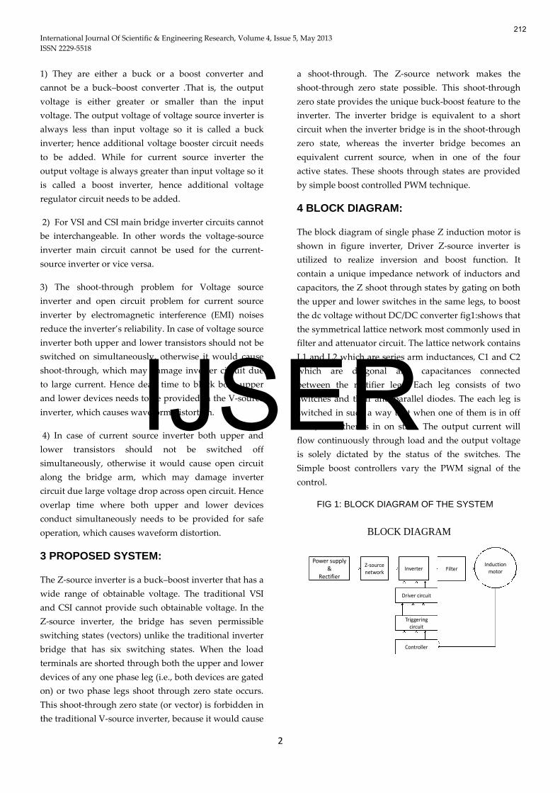
4 BLOCK DIAGRAM:
The block diagram of single phase Z induction motor is
shown in figure inverter, Driver Z-source inverter is
utilized to realize inversion and boost function. It
contain a unique impedance network of inductors and
capacitors, the Z shoot through states by gating on both
the upper and lower switches in the same legs, to boost
the dc voltage without DC/DC converter fig1:shows that
the symmetrical lattice network most commonly used in
filter and attenuator circuit. The lattice network contains
L1 and L2 which are series arm inductances, C1 and C2
which are diagonal arm capacitances connected
between the rectifier legs. Each leg consists of two
switches and their anti parallel diodes. The each leg is
switched in such a way that when one of them is in off
state, the other is in on state. The output current will
flow continuously through load and the output voltage
is solely dictated by the status of the switches. The
Simple boost controllers vary the PWM signal of the
control.
FIG 1: BLOCK DIAGRAM OF THE SYSTEM
BLOCK DIAGRAM
Power supply&
Rectifier
Z-sourcenetwork
Inverter Filter
Controller
Driver circuit
Triggeringcircuit
Inductionmotor
212
IJSER

International Journal Of Scientific & Engineering Research, Volume 4, Issue 5, May 2013
ISSN 2229-5518
3
5 OPERATION OF Z – SOURCE INVERTER:
The Z-source inverter consists of unique impedance
networks which couple the converter main circuit to the
power source, load, or other converter. The impedance
network consists of two inductors and two capacitors
connected to each other as shown in the fig.2 forms the
second order filter network. The values of both inductor
and both capacitor are equal. The two inductors can be
two separate inductors or two inductors inductively
coupled to each other on a single core. For size and cost
reduction film capacitors of desired value and voltage
rating can be selected.
FIG: 2 CIRCUIT DIAGRAM OF ZSI
FIG:3 EQUIVALENT CIRCUIT OF ZSI
We have three operating states in Z source
inverter. They are
1. Active state
2. Zero state
3. Shoot through zero state
The switching states of these operating states are
explained in table: 1
5.1 ACTIVE STATE:
In this mode, the inverter bridge is operating in one of
the four traditional active vectors; the equivalent circuit
is as shown in figure 4.The inverter bridge acts as a
current source viewed from the DC link. Both the
inductors have an identical current value because of the
circuit symmetry. This unique feature widens the line
current conducting intervals, thus reducing harmonic
current.
FIG: 4 ACTIVESTATE
5.2 ZERO STATE:The inverter bridge is operating in one of the two
traditional zero vectors and shorting through either the
upper or lower three device, thus acting as an open
circuit viewed from the Z-source circuit. Again, under
this mode, the inductor carry current, which contributes
to the line current’s harmonic reduction as shown in
below fig 5.
FIG:5 ZERO STATE
5.3 SHOOT THROUGH STATE:The inverter bridge is operating in one of the seven
shoot-through states. The equivalent circuit of the
inverter bridge in this mode is as shown in the below
fig: 6. In this mode, separating the dc link from the ac
line. This shoot-through mode to be used in every
switching cycle during the traditional zero vector period
generated by the PWM control. Depending on how
much a voltage boost is needed, the shoot-through
interval (T0) or its duty cycle (T0/T) is determined. It
can be seen that the shoot-through interval is only a
fraction of the switching cycle.
213
IJSER

International Journal Of Scientific & Engineering Research, Volume 4, Issue 5, May 2013
ISSN 2229-5518
4
FIG: 6 SHOOT THROUGH STATE
Table 1: SWITCHING STATES OF ZSI
6 ANALYSIS OF Z - SOURCE INVERTER:
The dc voltage source Vdc that is applied to the Z
Source inverter through reverse blocking diode D. All
traditional PWM techniques are applicable for Z-Source
inverter. During the shoot-through time (T0) the DC
link voltage Vdcl is boosted to a value greater than
input voltage, hence input diode will be reverse biased
blocking reverse flow of current. The detailed analysis
of Z-source inverter is given below. The average dc-link
voltage across the inverter is given by:
VdcTTVcVdc ))/01((1 (1)
Where,
Vdcl is the average dc link voltage equal to capacitor
voltage Vc, T is a switching period and T0 is shoot-
through time over a switching period.
The peak dc-link voltage across the inverter is expressed
as
BVdcVdcTTTpVdc ))21/((1 (2)
Where,
1)/021/(1)01/( TTTTTB(3)
B is the boost factor resulting from the shoot-through
zero state.
The output peak phase voltage from the inverter
can be expressed as;
2/MVipVacp (4)
Where,
M is the modulation index of PWM waveform,
Vacp is output peak phase voltage z inverter.
Using (2) and (4) peak phase voltage can be expressed
as
2/MBVdcVacp (5)
For the traditional V-source PWM inverter, the output
peak phase voltage is given by
2/MVdcVacp
Where,
Modulation index M is always less than unity
hence in traditional inverter the output voltage is
always less than input dc voltage. Equation (5) shows
that in Z-Source inverter the output voltage can be
stepped up and down by choosing an appropriate
buck–boost factor B.
The buck–boost factor is determined by the modulation
index M and boost factor B. For Z-source inverter the
boost factor is always greater than or equal to unity.
When boost factor is equal to unity the Z source inverter
acts like traditional inverter. The boost factor B as
expressed in (3) can be controlled by varying shoot
through duty cycle T0/T of the inverter PWM input.
7 SIMULATION:The single phase Z-source inverter Matlab /
Simulink model for speed control of induction motor is
shown in figure 6, it has two inductors L1=L2,
capacitors C1=C2. Simple boost control technique is
used for PWM signal. The simulation parameters are: 1)
Z-source network: L1 = L2 = 1mH, C1 = C2 = 1000 µF; 2)
Output filters: Lf = 1000mH, Cf = 5-50 µF; 3) switching
frequency: 10 kHz. Figure 6 shows the AC 165 Vrms
input is rectified using a diode rectifier. The rectified
DC pulsating signal is applied to the Z- source inverter
then the output of the inverter is fed to the auxiliary
winding and the motor's main winding is directly
SWITCHINGSTATES S1 S2 S3 S4
OUTPUTVOLTAGE
Activestates 1 0 0 1 Finite
voltage0 1 1 0
Zero states1 0 1 0 Zero
0 1 0 1
Shootthrough state
1 1 S3 S4 Zero
S1 S2 1 1
1 1 1 1
214
IJSER

International Journal Of Scientific & Engineering Research, Volume 4, Issue 5, May 2013
ISSN 2229-5518
5
connected to the 165 V utility supplies. The reference
value of the magnitude and phase of voltage applied to
the auxiliary winding are computed by the reference
voltage block. By varying the auxiliary winding voltage
magnitude and phase, the torque ripples are alleviated
at all operating points.
FIG 6: SIMULATION DIAGRAM OF ZSI FED
INDUCTION MOTOR
FIG:7SIMULATION DIAGRAM OF SHOOT THROUGH
STATE
FIG 8: MAIN & AUXILIARY WINDING CURRENT
FIG 9: ROTOR SPEED
FIG 10: LOAD&ELECTROMAGNETICTORQUE
FIG 11: MAIN &AUXILLARY VOLTAGE
FIG 12: SHOOT THROUGH STATE
215
IJSER

International Journal Of Scientific & Engineering Research, Volume 4, Issue 5, May 2013
ISSN 2229-5518
6
CONCLUSION:
This paper presents, the theoretical analysis and design
of Z-source inverter is studied. The Z-source inverter
employs a unique impedance network to couple the
inverter main circuit to the power source and thus
providing unique feature. The control methods with the
insertion of shoot-through states of Z-source inverter
have been studied. The proposed scheme under simple
boost control is simulated with the help of
MATLAB/SIMULINK and the simulation results are
obtained for different values of modulation indices. The
simulation results shows that both buck and boost
operations can be obtained in Z-source inverter by
varying Modulation index (M) or Boost factor (B) and
hence we can control the speed of the motor.
8 REFERENCES:
1. P.H. Zope, Prashant Sonare, Avnish Bora & Rashmi
Kalla, “Simulation and Implementation of Control
Strategy for Z-Source Inverter in the Speed control of
Induction Motor” , International Journal of Electrical
engineering and technology, June 2012 .
2. Atul Kushwaha, Mohd. Arif Khan, Atif Iqbal &
Zakir Husain, “Z- Source Inverter Simulation and
Harmonic Study”, Global Journal of advanced Engineering
Technologies, 2012.
3. Vrushali Suresh Neve, P.H. Zope, S.R. Suralkar,
“Analysis and Simulation of Z-Source Inverter Fed to
Single Phase Induction Motor Drive”, International
Journal of Scientific Engineering and Technology, Jan 2013.
4. Fang Zheng Peng, “Z-Source Inverter”, IEEE
Transactions on Industry Applications, March/April 2003.
5. Amol R. Sutar, Satyawan R. Jagtap, Jakirhusen
Tamboli, “Performance Analysis of Z-Source Inverter
Fed Induction Motor Drive”, International Journal of
Scientific & Engineering Research” May 2012.
6. Omar Ellabban, Joeri Van Mierlo, and Philippe
Lataire, “Experimental Study of the Shoot-Through
Boost Control Methods for the Z-Source Inverter”, EPE
Journal, June 2011.
7. S. Thangaprakash1, A. Krishnan, “Comparative
evaluation of modified pulse width modulation
schemes of Z-source inverter for various applications
and demands”, International Journal of Engineering,
Science and Technology, 2010.
8. Kun YU, Fang Lin LUO, Miao ZHU, “Implementation
of Maximum Constant Boost Control of Z-Source
Inverters Based on Space Vector Modulation
Technique”, IEEE Conference on Industrial Electronics and
Applications (ICIEA) , 2012.
9. Miaosen Shen, Jin Wang, Alan Joseph, Fang Z. Peng,
Leon M. Tolbert and Donald J. Adams, “Maximum
Constant Boost Control of the Z-Source Inverter”,
IEEE,2004.
10. Ishtiyaque Ahmad and Dr. R.K Tripathi, “Indirect
Field Oriented Control (IFOC) of Induction Motor Using
SVPWM Fed with Z source Inverter”, IEEE, 2012.
216
IJSER


![INVERTER DRIVES PRODUCT RANGE · 4 YASKAWA Inverter Drives Drive Selector 1 phase 3 phase Applicable motor Max. output [kW] Induction motor (IM) Permanent magnet motor (PM) Enclosure](https://img.pdfslide.us/doc/110x75/6005220642cce874457e0013/inverter-drives-product-4-yaskawa-inverter-drives-drive-selector-1-phase-3-phase.jpg)