Embed Size (px)
Citation preview

Bilz Vibration Technology AGBöblinger Straße 25D-71229 LeonbergTel +49 (0) 71 52 – 30 91-0Fax +49 (0) 71 52 – 30 91-10
©LO
FT-48.de · 03.2016 · 10.000 · W
e reserve the right to
make technical changes and typographical erro
rs.
www.bilz.ag
ENEN
Your expert for vibration insulationand machine setting technology
General catalogue

On the same wavelengthas our customers.
Bilz Vibration Technology AG is acompany that was founded in1985, which mainly deals with theinsulation of vibration and structure-borne noise of machin-ery and equipment. We havetaken a leading position in Europein this very specialized field as asupplier of mechanical and plantengineering to e.g. both the auto -motive and semiconductor indus-try and its suppliers.
Our company history:1985 Founded as BilzSchwingungs technik GmbH
2006 Transformation into a stockcompany and renamed Bilz
Vibration Technology AG
Our product range covers a verywide range of applications. Fromthe insulation of a single presswith insulation pads up to the aircushioning of highly sensitiveequipment in the semiconductorindustry, there is virtually no tech-nical vibration problem for whichwe cannot provide an efficient andcost-effective solution.
We are also always able to respondto different customer requirementsquickly and flexibly due to the highlevel of in-house vertical integra-tion.
2
BELGIUM / LUXEMBOURGSchiltz SA. NV.Chaussee de Gand 1034B-1082 BrusselsTel. + 32 2 4 64 48 45 Fax + 32 2 4 64 48 49 [email protected]
BOSNIA & HERZEGOVINA,KOSOVO, CROATIA, MACEDONIA, MONTENEGRO, SERBIA, SLOVENIAIB Blumenauer KGHauptstrasse 7D-83112 FrasdorfTel. + 49 8052 3 74 Fax + 49 8052 43 55 Mobile + 49 175 1 67 [email protected]
BRAZILHOMMEL-TECH Com. Imp. eExp. Ltda NOVO ENDEREÇO:Avenida Artur de Queirós, 134Bairro Casa BrancaBR-09015-510-Santo André -SP Tel. + 55 11 49 79 53 00 Fax + 55 11 44 36 68 [email protected]
BULGARIANikolay Marinow ET MesstechnikMladost, Bl.45, Vh.12, App.194BG-1784 Sofia Tel. + 359 2 9 74 45 70 Fax + 359 2 8 74 20 [email protected]
CHINABilz (Shanghai) Vibration Technology Co., Ltd.Room 1301, No 525, Chengyin Road Shanghai 200000P.R. ChinaTel. + 86 13 7 74 32 20 [email protected]
DENMARK/ICELANDTP GruppenKorskildelund 4DK-2670 GreveTel. + 45 70 10 09 66Fax + 45 70 10 01 [email protected] www.tp-gruppen.dk
ENGLANDPES (UK) LIMITEDWatling CloseSketchley Meadows Business ParkGB-Hinckley, Leics. LE10 3EZTel. + 44 1455 25 12 51Fax + 44 1455 25 12 52 [email protected]
FINLANDKvalitest Nordic Oy Huutokalliontie 20840800 Vaajakoski, FINLANDTel. + 35 8 4 05 52 98 [email protected]
FRANCE/VIB & TEC – TECHNOLOGIEANTIVIBRATOIRE2 rue de ColmarF-68220 Hésingue Tel. + 33 3 89 69 11 90Fax + 33 3 89 69 04 [email protected]
INDIAMachine House India Pvt. Ltd.W 82 (A) MIDC AMBADNashik, MaharashtraTel. + 91 253 2 38 22 55Fax + 91 253 2 38 60 [email protected]
IRANJ&M Global Trade E.K.Eupener Str. 161-E6050933 CologneGermanyTel. +49 (0) 221 50 60 87 41Fax +49 (0) 221 50 60 87 [email protected]
ISRAEL Baccara Geva Ltd.IL-1891500 Kvutzat GevaTel. + 972 4 653 59 60Fax + 972 4 653 14 [email protected]
ITALYGiquattro Srl.Via Aristotele 24 / 5I-20128 MilanoTel. + 39 2 2 55 31 70 Fax + 39 2 2 57 28 [email protected]
JAPANNabeya Co. Ltd.25 Wakasugicho, GifuZip-Code 500-8743 Tel. + 81 58 273 65 21Fax + 81 58 278 00 22 [email protected]
Metrotec Corporation2-25-35 Ohya-kita,Ebina City, KanagawaPref. 243-0419 Tel. + 81 46 206 00 11Fax + 81 46 206 00 22Mobil: + 81 90 77 23 39 [email protected]
NETHERLANDSOude Reimer BVWillem Barentszweg 216NL-1212 BR HilversumTel. + 31 35 6 46 08 20 Fax + 31 35 6 85 70 [email protected]
POLANDEKKONul. Poziomkowa 1B/13PL-11-041 Olsztyn Mobile + 48 792 88 64 [email protected]
PORTUGAL EQUINOTEC, SA.Av. Villagarcia de Arosa 1120P-4450-300 Matosinhos Tel. + 351 22 9 35 07 55 Fax + 351 22 9 35 10 [email protected]
ROMANIAPATRASCU & GANE ENGINEERING COMPANY S.R.L. Str. Dreptatii nr. 79B, Sector 6, RO-060883 BucurestiTel. + 40 212 22 95 40 Fax + 40 212 22 95 [email protected]
SWEDENSERVITEC NYQVIST ABFjällgatan 49 ASE 504 61 BoråsTel. + 33 22 88 66Fax + 33 22 88 67 Mobile +33 704 41 88 [email protected]
SWITZERLAND VIB & TEC – TECHNOLOGIEANTIVIBRATOIRE15, rue de Saint-LouisF-68220 Hésingue Tel. + 33 3 89 69 11 90Fax + 33 3 89 69 04 [email protected]
SPAINElorbi S.A.Botica Vieja 17Deusto, E-48014 Bilbao Tel. + 34 944 75 34 72 Fax + 34 944 47 38 [email protected]
SOUTH AFRICAFa. Remag (PTY) Ltd.Midrand, Midway ParkP.O. Box 2281ZA-1685 South AfricaTel. + 27 11 315 56 72Fax + 27 11 315 56 [email protected]
SOUTH KOREAYONG BEE TRADING CORPORATIONSaeol bldg., 82-4, Yangjae-dong, Seocho-gu,Seoul 137-130 KoreaTel. + 82 2 5 76 60 22Fax + 82 2 5 76 60 27 [email protected]
SOUTH EAST ASIA(SINGAPORE, THAILAND,MALAYSIA, VIETNAM, IN-DONESIA, PHILIPPINES)Bilz Asia Pacific Pte Ltd.152 Beach RoadGateway East Tower 14-03Singapore 189721Tel. + 65 63 69 61 90Fax + 65 63 69 37 68H/P+ 65 97 30 44 [email protected]
TAIWANJOIN STAR TRADING CO., LTD4th Floor, No. 3, Alley 6, Lane 45, Bao-Xing Rd.Hsin Tien District, New Taipei city 23145, Taiwan R.O.C.Tel. + 886 2 86 67 63 66Fax + 886 2 86 67 36 [email protected]
CZECH REPUBLIC,SLOVAKIAServistek S.R.OGajdosova 103CZ-615 00 BrnoTel. + 420 548 21 63 14Fax + 420 548 22 61 [email protected]
TURKEY MOTEKNO MAKINE SAN. VETIC. LTD. STI.Rihtim Cad. No. 59, Fransiz Geçidi C Blok 33 TR-34425 Karaköy, IstanbulTel. + 90 212 2 93 74 23Fax + 90 212 2 51 46 [email protected]
HUNGARY ROLL-N Ipari Kerekek Kft.Hunor u. 44-46H-1037 Budapest Tel. + 36 (1) 453-01 69Fax + 36 (1) 453-01 70 [email protected]
USA, CANADA, MEXICOBilz Vibration Technology, Inc. Att. Mr. Marc BrowerAtt. Mr. Bill GranchiPo Box 241305Cleveland, Ohio 44124 Tel. + 1 330 4 68 24 59Fax + 1 216 2 74 91 [email protected]
HEADQUARTERS
Bilz Vibration Technology AG
Böblinger Straße 25D-71229 LeonbergTel. +49 71 52 30 91-0Fax +49 71 52 30 91-10
SOUTH & AUSTRIA (POSTALCODE AREA 6)Michael HempelTel. +49 71 52 30 91-13Fax +49 71 52 30 91-10Mobile +49 171 4 22 40 [email protected]
SOUTH-WESTDipl.-Wirt. Ing. (FH) Emilio MorreaTel. +49 71 52 30 91-35Fax +49 71 52 30 91-10Mobile +49 170 2 14 87 [email protected]
SOUTH-EAST & AUSTRIA(WITH THE EXCEPTION OFPOSTAL CODE AREA 6)Dipl.-Ing. (FH) Marijana PetrovicTel. +49 84 53 43 67-10 Fax +49 84 53 43 67-30 Mobile +49 171 7 19 08 [email protected]
CENTRALDipl.-Ing. (FH) Peter DaxerTel. +49 60 31 79 09 23 Fax +49 60 31 79 09 23 Mobile +49 151 25 08 92 [email protected]
EASTFrank RückertTel. +49 35 23 6 32 11Fax +49 35 23 6 25 21Mobile +49 172 3 70 51 [email protected]
WESTDipl.-Ing. ElektrotechnikDipl.-Wirt. Ing. Martin KamannTel. +49 28 35 95 33 88Fax +49 28 35 95 31 74Mobile +49 170 2 01 35 [email protected]
NORTHHelge BöttleTel. +49 441 99 89 04 40Fax +49 441 9 62 02 94 Mobile +49 170 2 45 43 [email protected]
91
Right to make changes is reserved. Current addresses can be found at www.bilz.ag/en
INTERNATIONAL GERMANY

To keep this catalogue as clear aspossible, we have limited ourselvesto the most common variants ofour products.
If you can’t find a solution suitablefor you, please contact us, we’rehere to help!
The Bilz team is available tocompetently answer furtherquestions at any time.
Quality to us means that our products,services and solutions fully meetyour expectations and specifica-tions. And we do not orientourselves to a relative scale.We accept only the very bestquality measured against the mostmodern scientific and technolog-ical knowledge.
Delivery times must be kept as short as possible.Our comprehensive stock inLeonberg makes us a reliablepartner when it comes to punctu-ality and short delivery times.
The prices of our systems and componentsrepresent a fair equivalent value toour innovative strength and serviceprofessionalism. We place greatvalue on retaining this balance andto ensure that this ratio issustained.
Technical competence is achieved through the continuoustraining of our engineers andspecialists who constantly embarkupon new developments and whowork at the cutting edge oftechnology.
Comprehensive service offering on-site problem analysis,design and planning, manufacture,installation and commissioning aswell as after-sales support all froma single source.
A close partnershipand long-term relationships withour customers and suppliers arevery important to us.
3

4
Bilz Vibration Technology AG

5
Quality made in Germany
Worldwide distributionWe are present in almost all parts of the world throughour global distribution network and offer our customerson the spot expert advice, services and of course oursolutions for vibration insulation.
Made in GermanyThe development, design, construction, manufactureand assembly of our products and solutions is central-ized at our headquarters in Leonberg. This enables usto offer you the quality that you expect.
The headquarters of Bilz Vibration Technology AGencompassing management, assembly, qualityassurance and warehousing, are located inLeonberg near Stuttgart.
The family tradition has now been continued forthree generations. Our entrepreneurial thinking ischaracterized by long-term concepts and vision andis not aimed at short-term profit maximization.
As a result, our revenues and number of employeeshas continued to grow steadily since the companywas founded in 1985.

6
When solutions are requiredquality makes the difference.
We have set up a training anddemonstration centre at ourheadquarters. Here we can showour customers all our productsfrom Bilz insulation pads to ourActive Isolation System AIS™ withsix degrees of freedom in aconstructive and pleasant atmos-phere. We regularly hold seminarsand trainings here for ouremployees and customers and forour global network of agencies.
As a customer, you always havethe option of coming along todiscuss and inspect the function-ality, benefits and structure ofvarious Bilz insulating systemsbefore placing an order. Theengineers and technicians at BilzAG are provided with severalmodifiable vibration test benchesto facilitate the continuous devel-
opment and improvement of ourproducts and solutions. Theseenable us to perform exhaustivetesting aimed at improving qualityand realisation of customer-specific designs. The tests can alsobe performed both in the naturalfrequency range of Bilz vibrationinsulators and the frequency rangeof relevant land and building structures. The use of test beds in combina-tion with the latest 3D simulationand calculation programs enablesus to review your particularboundary conditions in advance,guaranteeing the design mostsuitable for the application.

7
Your benefits from Bilz technology and know-how
n Optimum vibration and structure-borne noise insulationn Effective protection of persons, environment and buildingsn Quality improvements through reduced manufacturing
tolerances and increased manufacturing precisionn Increased production throughput by shortening cycle
times in productionn Cost reductions through simplified and flexible machine
installationn Quality and safety through compliance with the latest
standards, directives and guidelinesn DIN ISO 9001n EC Machinery Directiven EC Low Voltage Directiven EC EMC Directive
General 7–9
Insulation pads 10–19
Levelling elements 20–27
Precision levelling wedges 28–38
FAEBI® rubber air springs 39–46
BiAir® membrane air springs 47–49
Level control 50–52
EPPC™ 53–54
Active Isolation System AIS™ 55–63
Room acoustics/sound insulation 64–65
Magnetic field compensation 66–67
Vibration insulated tables 68–74
Indirect insulation 75–87
Measuring instruments 88–89
Contact addresses 90–91
Content

8
General information onvibration technologyDemands on the design and operation of modern machinery and equipment continueto escalate. The technical capabilities of today’s machines in terms of machining speed,dynamic load changes and achievable precision, as well as the key features of thegeometry and the properties of the materials used have grown steadily over recentyears. However, this also increases the need to reduce the transmitted vibrations andstructure-borne noise. This concerns both the emission of vibrations (source insula-tion), for example in metal-working machines, as well as machines being subject tovibrations (receiver insulation), e.g. in measuring machines. The importance ofmeasures to protect people, buildings and the environment also continues to grow.
Damping is the physical property of aninsulator to remove energy of a vibratingsystem. This limits the vibrations to anacceptable level and converts mechanicalenergy into heat.
Insulation means the decoupling ofdisturbance forces and vibrations. Thiseffect always works in both directions,that is from the machine to the environ-ment as well as in the opposite direction.
Source insulation is the vibration-isolated mounting of a machine in orderto reduce its pulse or sinusoidal vibrationforces. This protects objects in theenvironment such as adjacent machines,the building and people from thedisturbing forces.
The special task here is to keep themovement of the now elasticallymounted machine within its operationallimits.
In the case of receiver insulation it isnecessary to protect vibration-sensitiveequipment (e.g. measuring machines)from interfering ground vibrations. The production or characterization ofever smaller components, down to struc-tures consisting of a few atoms ormolecules, make heavy demands onfacilities and their vibration insulation.
Passive vibration isolators exhibitupon excitation an amplification ofthe vibration amplitude in the rangeof the natural frequency. Thisresonance amplification is dependenton the damping characteristics of theisolators.
Active vibration isolators generate a counter-force phase-shifted by 180° through a suitablecontrol; the isolators act as actuators. The resonance amplification in thenatural frequency range of the isola-tors is minimized. An optimum isolating effect isachieved with frequencies above theresonance range.
DEFINITION OF TERMS

9
Vibration control matching
Insulation of periodically excited vibrationsThe effect of vibration insulation depends mainly on the ratio ofthe disturbance frequency or excitation frequency to the naturalfrequency of the insulator (matching ratio), and its damping. With source insulation the excitation frequency is the machinespeed or stroke rates, with receiver insulation disturbing groundvibrations. Generally it can be said that the lower the naturalfrequency of the insulator the better the efficiency of theinsulator, i.e., the larger the ratio of disturbing frequency iscompared to the natural frequency. The resulting graph showsthat an isolating effect only occurs when the value of the harmo-nizing ratio is greater than √¬2. At smaller values an amplification(resonance magnification) of the disturbing force may also occur.
Usually a matching ratio of between 3 and 4 is striven for,whereby 3 is considered the technical lower limit and 4 theeconomic upper limit. A matching ratio larger than 4 cannotnormally be justified from the economic perspectivebecause the material expense would increase above averagecompared to the degree of insulation.
Essential characteristics of shock are its duration, its distri-bution and its intensity.
With shock insulation, the dynamic disturbing pulse,consisting of a high power peak over a short period oftime, generated e.g. by presses, stamps or hammers, ischanged to a longer lasting pulse with smaller forces.
Unlike periodically excited vibrations the isolated systemoscillates at the excited natural frequency of the isolatedsystem and not in accordance with the excitation, forexample, the number of strokes. This can be comparedwith a tuning fork, which always produces a sound of aconstant pitch.
Js = 1 -
fiso Natural frequency of the isolated system
Efficiency of shock insulation
INSULATION OF SHOCK
f fix Natural frequency of the system on its ridged-base foundation.
ffix
fiso
Transmission factor Vs of the vibration insulationwithout damping:
Disturbing or exciting frequency
Natural frequency of the insulator
Matching ratio
The transmission factor Vptaking into account thedamping ratio D is:
VS = 12 2-2 1-
-
VP =1 22D+ 42 2(1 )- 22D+ 4
f distf O
f distf O
=
Undamped steel spring
Matching ratio Ƞ
Tran
smission
factor m
atch
ing VP

10
Insulation padsBilz insulation pads have been used successfully for many years in a variety of indus-tries as an economical solution in the fight against problems caused by vibration andstructure-borne noise. Made from a precisely defined combination of nitrile rubber and cork particlesembedded in a composite of cotton fibres, the physical and mechanical properties ofthis high-quality composite material meet all of the current requirements for variousindustrial applications depending on type of pad. Very good damping properties ensureoptimum deflection and level consistency both under static and under dynamicloading. The material composition used ensures secure anti-slip protection on conventionalindustrial floors. It has high resistance properties particularly to modern cooling lubricants.

11
Avoiding vibration and structure-borne noise problems has alwaysbeen in our focus during the development of Bilz insulating pads.As, depending on the type of machine, the requirements can bevery different because of the dynamic particularities, there arenumerous different types of pads available for almost any vibra-tion problem. Especially noteworthy are the excellent compres-sion set values of our insulation pads. This property is particularlyimportant in vibration-isolated mounting of modern machinesbecause the geometric accuracy must remain unchanged andstable for years.
Structure-borne noiseEffective noise insulation
Ageing resistant Virtually unlimited service life with adherence to load values. Nopermanent changes in shape.
Chemical resistanceExceptionally good resistance to oils, grease, acids and coolingemulsions used in industry.
Temperature resistance-20 °C to +120 °C
Damping propertiesVery high degree of damping of up to 30 %
Mineral oilsCommon water-miscible cooling lubricants, ATF (Automatic Trans-mission Fluid), cooling lubricants, water-miscible anti corrosiveoils, slideway oils, compressed air oils, lubricating oils, heattransfer oils, filter oils, rolling oils, automotive gear oils, brakefluids based on mineral oil
Cleaning agentsHydro-chlorofluorocarbons, benzene, cold cleaner
Cleaning agent (aqueous solutions)Washing and cleaning agents, wetting agents, dilute acids, dilutealkalis, salt solutions
LubricantsGreases for plain and roller bearings, gear greases
Synthetic lubricantsPolyalkylene, carboxylic acid esters, antifreeze
Combustibles and fuelsPetrol, diesel fuel, heating oil, aviation fuel, special fuels
Fire resistant hydraulic fluids Oil-in-water emulsions, water-in-oil emulsions, aqueous polymersolutions
Bilz insulation pads are resistant to the following substances:
Free-standing machinefoundations using Bilz insula-tion pads with low demandson alignment. The unevenfloor is compensated for withpads, etc. The arrangementof the pads is usually apattern of points, not overthe full surface. Number andsize of the required insula-tion pads is given by theweight of the machine andthe existing support surface.
Stable connection to themachine bed using bolt-oninstallation fittings thatremain in place when themachine is lifted. Specificallyfor machines with highdynamic forces (injectionmoulding machines,stamping equipment, etc.).
Bolt-through groundanchoring using insulationpads and insulation washers.The use of insulationwashers prevents vibrationsbeing transmitted throughthe bolt.
Highly effective shock andvibration insulation by Bilzinsulation pad sets.Different Bilz pads arecombined into pad setsoffering significantlyimproved insulation.
FOUR POSSIBLE OPTIONS FOR THE USE OF INSULATION PADS FOR MACHINE INSTALLATION
1 2 3 4

12
1000 mm 500 mm 250 mm 200 mm 150 mm 100 mm 75 mm 50 mm
500 mm
250 mm
150 mm
100 mm
75 mm
50 mm
200 mm
SQUARE
Available standard formats square Special and other formats are individually made on request
SQUARE B4 B0 B6 B5 B50 B32 B32W B30 B30W B13W BS1 BS BN BR7 B8
mm
1000 x 500 01-0202 01-0005 01-0323 01-0260 01-0291 01-0139 01-0175 01-0057 01-0087 01-0038 01-0462 01-0441 01-0371 01-0391 01-0350
500 x 500 01-0223 01-0027 01-0342 01-0280 01-0310 01-0158 01-0194 01-0079 01-0106 01-0051 01-0473 01-0458 01-0384 01-0406 01-0365
500 x 250 01-0222 01-0026 01-0341 01-0279 01-0309 01-0157 01-0193 01-0078 01-0105 01-0050 01-0472 01-0457 01-0383 01-0405 01-0364
250 x 250 01-0217 01-0020 01-0337 01-0274 01-0305 01-0153 01-0189 01-0072 01-0101 01-0048 01-0470 01-0453 01-0380 01-0402 01-0361
250 x 150 01-0216 01-0019 01-0336 01-0273 01-0304 01-0152 01-0188 01-0071 01-0100 01-0047 01-0469 01-0452 01-0379 01-0401 01-0360
200 x 200 01-0214 01-0016 01-0334 01-0271 01-0302 01-0150 01-0186 01-0069 01-0098 01-0046 01-0468 01-0450 01-0378 01-0400 01-0359
200 x 100 01-0213 01-0015 01-0333 01-0270 01-0301 01-0149 01-0185 01-0068 01-0097 01-0045 01-0467 01-0449 01-0377 01-0399 01-0358
150 x 150 01-0210 01-0012 01-0330 01-0267 01-0298 01-0146 01-0182 01-0065 01-0094 01-0043 01-0465 01-0446 01-0375 01-0397 01-0356
150 x 100 01-0209 01-0011 01-0329 01-0266 01-0297 01-0145 01-0181 01-0064 01-0093 01-0042 01-0464 01-0445 01-0374 01-0396 01-0355
150 x 75 01-0211 01-0013 01-0331 01-0268 01-0299 01-0147 01-0183 01-0066 01-0095 01-0044 01-0466 01-0447 01-0376 01-0398 01-0357
100 x 100 01-0204 01-0006 01-0324 01-0261 01-0292 01-0140 01-0176 01-0058 01-0088 01-0039 01-0463 01-0442 01-0372 01-0392 01-0351
100 x 50 01-0205 01-0007 01-0325 01-0262 01-0293 01-0141 01-0177 01-0060 01-0089 01-0040 - - 01-0373 01-0393 01-0352
75 x 75 01-0228 01-0034 01-0346 01-0284 01-0313 01-0162 01-0198 01-0083 01-0110 01-0053 - - 01-0388 01-0409 01-0369
50 x 50 01-0224 01-0029 01-0343 01-0281 01-0311 01-0159 01-0195 01-0080 01-0107 01-0052 - - 01-0385 01-0407 01-0366
Note
n Bilz insulation pads can be cut with any circular or band saw.
n We are happy to supply special sizes on request.
n The specified maximum load is composed of static and dynamic loading of the machine. The best insulation effect is achieved at approximately 80-90 % of the specified maximum load.
n Selected insulation pads can also be supplied with a profile on one side (designated for example B4-1).
n The stated coefficient of friction refers to conventional industrial screed.
n Cutting tolerance is according to DIN 7715/T5, class P3.
n W: Waffle structure designs for compensation of uneven floors (B32W, B30W, B13W)
Right to make technical changes is reserved.
ITEM NUMBERS AND STANDARD SIZES

13
Application B4 B0 B6 B5/B50 B32/B32W B30/B30W B13W
Metal processing Machining centre Drilling machine Boring mill Lathe Lathe, long bed Milling machine Press Saw Guillotine shear Grinding machine Punching/nibbling machine Transfer line
Plastic processing Granulator Mills and boring mill Injection moulding machine
Printing and paper industry Book binding-/printing machine, folder Shearing, packing systems
Measuring and inspection Measuring machines, scales, microscope
Plate sets Foundation
ROUND
O/ 300 mm O/ 238 mm O/ 200 mm O/ 150 mm O/ 110 mm O/ 75 mm O/ 50 mm
ROUND B4 B0 B6 B5 B50 B32 B32W B30 B30W B13W BS1 BS BN BR7 B8
Ø mm
50 01-0220 01-0024 01-0339 01-0277 01-0307 01-0155 01-0191 01-0076 01-0103
75 01-0227 01-0033 01-0345 01-0283 01-0312 01-0161 01-0197 01-0082 01-0109
110 01-0206 01-0008 01-0326 01-0263 01-0294 01-0142 01-0178 01-0061 01-0090
150 01-0208 01-0010 01-0328 01-0265 01-0296 01-0144 01-0180 01-0063 01-0092 These types of pads are available on request.
200 01-0212 01-0014 01-0332 01-0269 01-0300 01-0148 01-0184 01-0067 01-0096
238 01-0215 01-0018 01-0335 01-0272 01-0303 01-0151 01-0187 01-0070 01-0099
300 01-0218 01-0021 01-0338 01-0275 01-0306 01-0154 01-0190 01-0073 01-0102
Available standard formats round
SELECTION OF THE APPROPRIATE TYPE OF PAD

14
PAD TYPE B4(2) DYNAMIC NATURAL FREQUENCY
High universal variant.Can be used for machinetools, plastic machines andprinting machines. Very wellsuited for machines with atendency to “wander”.
Type Load(1) Height Coefficient N/cm2 mm of friction(3)
B4 30-100 15 0.8
PAD TYPE B0 DYNAMIC NATURAL FREQUENCY
Variant without profiles. Verygood level consistency.Specifically for machines withlow intrinsic rigidity such asmachining centres, lathes andgrinding machines, etc.
Type Load(1) Height Coefficient N/cm2 mm of friction(3)
B0 50-200 15 0.6
PAD TYPE B6 DYNAMIC NATURAL FREQUENCY
Variant without profiles.Extremely high loadcapacity with the highestlevel consistency. For veryheavy and long-bedmachines.
Type Load(1) Height Coefficient N/cm2 mm of friction(3)
B6 50-350 15 0,6
Right to make technical changes is reserved.
Load [N/cm2]
vertical
horizontal
vertical
horizontal
vertical
horizontal
Natural frequency [Hz]
Natural frequency [Hz]
Natural frequency [Hz]
Load [N/cm2]
Load [N/cm2]
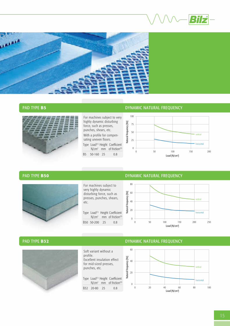
Soft variant without aprofile. Excellent insulation effectfor mid-sized presses,punches, etc.
Type Load(1) Height Coefficient N/cm2 mm of friction(3)
B32 20-80 25 0.8
PAD TYPE B32 DYNAMIC NATURAL FREQUENCY
PAD TYPE B5 DYNAMIC NATURAL FREQUENCY
For machines subject to veryhighly dynamic disturbingforce, such as presses,punches, shears, etc.
With a profile for compen-sating uneven floors.
Type Load(1) Height Coefficient N/cm2 mm of friction(3)
B5 50-160 25 0.8
PAD TYPE B50 DYNAMIC NATURAL FREQUENCY
For machines subject tovery highly dynamicdisturbing force, such aspresses, punches, shears,etc.
Type Load(1) Height Coefficient N/cm2 mm of friction(3)
B50 50-200 25 0.8
15
D
vertical
horizontal
Natural frequency [Hz]
Load [N/cm2]
vertical
horizontalNatural frequency [Hz]
Load [N/cm2]
vertical
horizontal
Natural frequency [Hz]
Load [N/cm2]
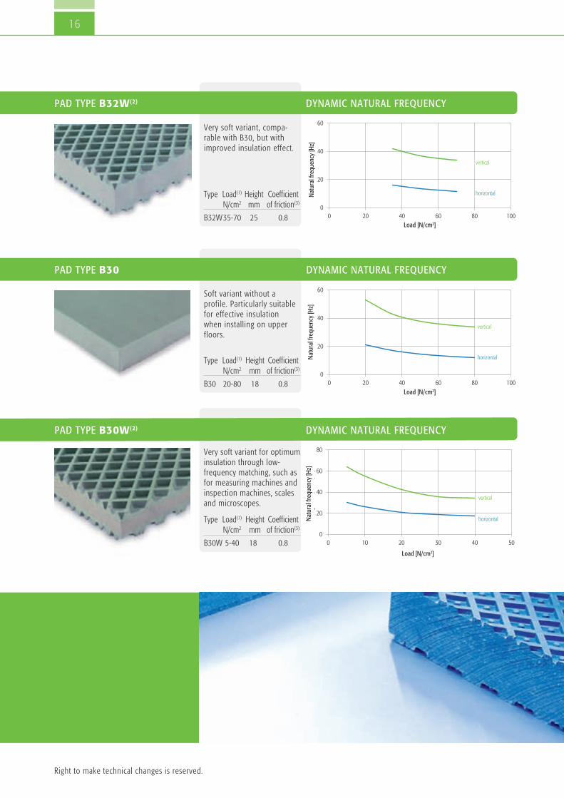
Very soft variant for optimuminsulation through low-frequency matching, such asfor measuring machines andinspection machines, scalesand microscopes.
Type Load(1) Height Coefficient N/cm2 mm of friction(3)
B30W 5-40 18 0.8
Soft variant without aprofile. Particularly suitablefor effective insulationwhen installing on upperfloors.
Type Load(1) Height Coefficient N/cm2 mm of friction(3)
B30 20-80 18 0.8
16
PAD TYPE B32W(2) DYNAMIC NATURAL FREQUENCY
PAD TYPE B30 DYNAMIC NATURAL FREQUENCY
PAD TYPE B30W(2) DYNAMIC NATURAL FREQUENCY
Very soft variant, compa-rable with B30, but withimproved insulation effect.
Type Load(1) Height Coefficient N/cm2 mm of friction(3)
B32W35-70 25 0.8
Right to make technical changes is reserved.
vertical
horizontalNatural frequency [Hz]
Load [N/cm2]
vertical
horizontalNatural frequency [Hz]
Load [N/cm2]
vertical
horizontalNatural frequency [Hz]
Load [N/cm2]

Special variant for thehighest insulation values.Can be stacked up to 5times. Matching up toapproximately 8 Hz. Perfectlysuited as a pad set forfoundation insulation.
Type Load(1) Height Coefficient N/cm2 mm of friction(3)
B13W 5-40 13 0.8
PAD TYPE B13W DYNAMIC NATURAL FREQUENCY
17
Bilz anti-slip and distancepads.No vibration insulation!
Type Load(1) Height Coefficient N/cm2 mm of friction(3)
BS1 10-400 1 0.9
BS 10-400 2 0.9
BN 10-300 5 0.6
BR7 10-160 7 0.8
B 8 5-40 8 0.8
PAD TYPE BS1, BS, BN, BR7(2), B8 ANTI-SLIP PADS
Note
n Bilz insulation pads can be cut with any circular or band saw.
n We are happy to supply special sizes on request.
n (1) The specified maximum load is composed of static and dynamic loading of the machine. The best insulation effect is achieved at approximately 80-90 % of the specified maximum load.
n (2) Can also be supplied with a profile on one side (designated for example B4-1).
n (3) The stated coefficient of friction refers to conventional industrial screed.
n Cutting tolerance is according to DIN 7715/T5, class P3.
vertical
horizontal
Natural frequency [Hz]
Load [N/cm2]

18
Insulation pad setsMultiple layering of Bilz insulation pads can achieve significantly reduced naturalfrequencies and therefore considerably increase the insulation effect compared with asingle layer of insulation pads.
These pad sets are particularly suitable for large machines and sprung foundations.The vibration insulation and damping properties of these insulation pads remainunchanged even after years of dynamic loading.
Bilz insulation pads are resistant against the most common greases, oils, coolants,cleaning agents as well as acids and alkalis.

Horizontal
(Pre) load [N/cm2]
Nat
ural
freq
uenc
y ve
rtic
al [H
z]N
atur
al fr
eque
ncy
horiz
onta
l [H
z]
Length mm 500 250 200 166 150 Width mm
500250200166150
19
Insulation pad setsApplication
n Effective insulation pads for highly dynamic machines andfoundations.
n The permissible load capacity of a pad lies between 5 and40 N/cm2 depending on the application. The number and sizeof the insulating layers and the required distribution of thepad sets is determined specifically for the application by Bilz.
For further information contact us to arrange a personal consultation.
Type Thickness Natural frequency Natural frequency unloaded vertical horizontal mm Hz HzB13W/B8, 2-layer 34 14.5 - 26.5 5.5 - 12.5B13W/B8, 3-layer 55 12.0 - 22.0 4.5 - 10.0B13W/B8, 4-layer 76 10.0 - 18.5 3.5 - 8.0B13W/B8, 5-layer 97 8.0 - 15.0 3.0 - 7.0B13W/B8, 6-layer 118 6.5 - 12.5 2.5 - 6.5
STANDARD SIZES
Vertical
NATURAL FREQUENCY
Foundation pit with Bilz insulation pads laid out
Foundation pit
Concrete block
(Pre) load [N/cm2]
When ordering please state the desiredsize.
Standard Item no. 01-0476
Special sizes Item no. 01-0475
SQUARE
Right to make technical changes is reserved.

20
Levelling elementsBilz levelling elements are used for vibration and structure-borne noise insulatedmachine installation. The maintenance-free machine feet guarantee the simple andprecise levelling of machines and are available in many versatile designs. The sizes and insulation pads are selected according to the application and load. Therange of levelling can be adapted depending on the selected bolt length and theindividual requirements.
General information
n The type of insulation pads used can be found in the type description, e.g. BNSH 80/50 is equipped with B50, BNVS 50/30W with B30W etc.
n The specified maximum load is composed of static and dynamic loading of the machine. The best insulation effect is achieved at approximately 80-90 % of the specified maximum load.
n Details on the properties of the insulation pads used can be found on pages 14-17.
n Permissible temperature range: -20 °C bis +120 °C
n A table for selecting the available bolts can be found on pages 26-27.They are supplied complete with nuts and washers.
n Please contact us if the size, colour, insulation pad mounting, or bolts that you are looking for are not listed. In additionto our standard solutions and colours we also carry numerous special solutions. We are always happy to offer our advice.

BNSHA
BNSH
H
G
21
Series BNSH /BNSHA
Application: Specifically developed for the mounting of injection mouldingmachines, presses, punches etc. Optimum load distribution due to our provenpressure plate design. Very high horizontal stability over the entire levelling range.The BNSHA elements with bolt-on floor plate are particularly suitable for allmachines that tend to wander. The floor anchor is not used as a safeguard againsttipping.Insulation pad properties: B50: Good insulating effect when the machine is installed on natural ground. Very well suited for machines with highly dynamic forces.B32: Very good insulation effect. Specifically developed for mounting on upper
floors or insufficiently stable supporting surfaces. Bolts: For the suitable levelling bolts see Table 2, p. 27.Colour: RAL 7037, dusty grey
D
BNSH / BNSHA
Type Item no. Item no. max. load H H O/ D Adjustment Thread PitchBNSH / BNSH BNSHA N/pc.. BNSH BNSHA rangeBNSHA mm mm mm mm G70/0* 12- 0042 12-0016 5.000 31 36 80 +6 M10 1.2580/50 12- 0047 12- 0020 9.500 43 48 96 +18 M12 1.5120/50 12- 0024 12- 0003 20.000 51 56 133 +18 M16 1.5160/50 12- 0028 12- 0006 40.000 52 57 175 +17 M20 1.5175/50 12- 0032 12- 0009 45.000 56 64 193 +17 M20 1.5200/50 12- 0036 12- 0012 65.000 63 71 229 +16 M24 2.0250/50 12- 0040 12- 0015 90.000 67 75 270 +15 M30 2.0
70/30* 12-0043 12-0017 1.800 34 39 80 +6 M10 1.2580/32 12- 0045 12- 0018 4.800 43 48 96 +18 M12 1.5120/32 12- 0022 12- 0001 9.600 51 56 133 +18 M16 1.5160/32 12- 0026 12- 0004 17.000 52 57 175 +17 M20 1.5175/32 12- 0030 12- 0007 20.800 56 64 193 +17 M20 1.5200/32 12- 0034 12- 0010 29.000 63 71 229 +16 M24 2.0250/32 12- 0038 12- 0013 41.000 67 75 270 +15 M30 2.0
Type L A B C E d mm mm mm mm mm mmBNSHA 70 125 15 75 105 8 5BNSHA 80 140 15 90 120 8 5BNSHA 120 180 15 125 160 13 5BNSHA 160 220 15 170 200 16 5BNSHA 175 260 20 185 230 20 8BNSHA 200 300 20 225 270 20 8BNSHA 250 330 20 265 300 20 8
BNSH BNSHA
Round, without/with bolt-on floor attachment.
BNSHA DIMENSION BASE PLATE
H
G
Ø D
G
Ø D
dH
C
EB
A
AL
Right to make technical changes is reserved.
* Special mounting

22
Series BNV /BNVS
Application: Proven and very effective plate element, preferably for lightto medium heavy machines with matching locating holes in the machinefeet. The BNV/BNVS elements are used where a ridged joint is requiredbetween the machine and the fitting. Any unevenness or angular differ-ences in the floor up to ± 3° can be compensated for using the movablelevelling bolt.
Insulation pad properties: B4: Medium hard pad with good vibration and structure-born
noise insulation. Universal application.
B0: Non profile insulation pad with very high levelling consistency, e.g. for lathes, machining centres etc.
B30W: Soft matching for a very good insulation effect, e.g. for grinding machines, test equipment, measuring machines, etc.
Bolts: For the suitable levelling bolts see Table 1, p. 26Colour: RAL 7037, dusty grey
BNV / BNVS (SQUARE)
Square, without/with flexible levelling bolt
Type BNV / Item no. Item no. max. load L W HBNVS BNV BNVS N/pc. mm mm mm 50/4 08- 0030 10- 0013 2.000 60 60 2280/4 08- 0034 10- 0023 4.700 85 85 24 110/4 08- 0004 10- 0004 12.000 123 123 28115/4 08- 0008 10-0026 11.400 163 88 29150/4 08- 0016 10- 0009 18.000 147 147 32200/4 08- 0020 10-0025 37.000 264 165 3550/0 08- 0028 10- 0011 4.000 60 60 2280/0 08- 0032 10- 0021 9.500 85 85 24110/0 08- 0002 10- 0002 24.000 123 123 28115/0 08- 0006 10-0027 22.800 163 88 29150/0 08- 0014 10- 0007 36.000 147 147 32200/0 08- 0018 10-0028 74.000 264 165 3550/30W 08- 0029 10- 0012 950 60 60 2580/30W 08- 0033 10- 0022 2.300 85 85 27110/30W 08- 0003 10- 0003 5.000 123 123 31115/30W 08- 0007 10-0029 4.500 163 88 32150/30W 08- 0015 10- 0008 7.300 147 147 35200/30W 08- 0019 10-0030 15.000 264 165 38BNVS
BNV
BNVS
L
H
B
L±3°
Right to make technical changes is reserved.

BNR / BNRS (ROUND)
23
Series BNR /BNRSRound, without/with flexible levelling bolt
Type BNR / Item no. Item no. max. load O/ D H BNRS BNR BNRS N/pc. mm mm50/4 09- 0035 11- 0014 1.700 60 2170/4 09-0048 11- 0019 3.600 79 2980/4 09- 0045 11-0023 4.200 85 23110/4 09- 0006 11- 0004 9.100 120 33150/4 09- 0016 11- 0009 17.000 162 29200/4 09- 0025 11-0026 31.000 213 3250/0 09- 0033 11- 0012 3.400 60 2170/0 09-0049 11- 0017 7.200 79 2980/0 09- 0042 11-0024 8.400 85 23110/0 09- 0002 11- 0002 18.200 120 33150/0 09- 0012 11- 0007 34.000 162 29200/0 09- 0021 11-0027 62.000 213 3250/30W 09- 0034 11- 0013 700 60 2470/30W 09-0050 11- 0018 1.400 79 3280/30W 09- 0043 11-0025 1.600 85 26110/30W 09- 0003 11- 0003 3.500 120 36150/30W 09- 0013 11- 0008 6.900 162 32200/30W 09- 0022 11-0028 12.000 213 35
BNRS
BNRS
BNR
Application, Properties and bolts:See type BNV/BNVS
H
Ø D
Ø D
±3°

BNRV
BNRSV
24
Application: Food, luxury food, packaging, chemical and pharmaceuticalindustries as well as clean room applications.
Insulation pad properties: B4: Medium hard pad with good vibration and structure-born
noise insulation. Universal application.
B30W: Soft matching for a very good insulation effect, e.g. for grinding machines, test equipment, measuring machines, etc.
BR7: Anti-slip plate without vibration insulation.Bolts: For suitable levelling bolts with standard thread see Table 1, p. 26.
BNRV / BNRSV
BFE
Series BNRV /BNRSV stainless-steel design
Round, stainless-steel design, without/with flexible levelling bolt
Application: Cost-effective stainless steel design with adequate vibration insulation forthe food, luxury food, packaging, chemical and pharmaceutical industries.Bolts: For suitable levelling bolts with standard thread see Table 3, p. 27.Note: These elements are also available in an electrically conducting design on request.
Series BFE stainless-steel designRound, stainless-steel design, with flexible levelling bolt
Type BNR / Item no. Item n0. max. load O/ D H BNRSV BNRV BNRSV N/pc. mm mm 50/4 30- 0031 30- 0014 1.700 54 2470/4 30- 0035 30- 0018 3.600 76 25110/4 30- 0023 30- 0007 9.100 116 27.5150/4 30- 0027 30- 0011 17.000 156 29.550/30W 30- 0030 30- 0013 700 54 2770/30W 30- 0034 30- 0017 1.400 76 28110/30W 30- 0022 30- 0006 3.500 116 30.5150/30W 30- 0026 30- 0010 6.900 156 32.550/BR7 30- 0032 30- 0016 2.800 54 1670/BR7 30- 0036 30- 0020 5.800 76 17110/BR7 30- 0024 30- 0009 14.500 116 19.5150/BR7 30- 0028 30- 0012 27.500 156 21.5
Type Item no. max. load O/ D HBFE BFE N/pc. mm mm 50 30- 0003 3.000 50 14 80 30- 0004 8.500 80 17 100 30- 0001 20.000 100 19 125 30- 0002 30.000 125 19
BNRSV
H
Ø D
Ø D
±3°
HØ D
Ø D
±7.5°
Right to make technical changes is reserved.

25
Series GMA and BNL
Type Item no. max. load O/ D H Adjustment G LengthBNL BNL N/pc. mm mm range mm80 14-0001 5.000 80 39 +11 M12 x 1.25 120120 14-0002 11.000 120 47 +12 M16 x 1.5 120 160 14-0003 26.000 160 54 +12 M20 x 1.5 170200 14-0004 40.000 200 58 +12 M20 x 1.5 170
Type Item no. O/ A B F M CF L S max. pressure load. max. deflection ThreadGMA mm mm mm mm mm mm mm N/pc. mm G63 13-0003 63 30 9 14 89 110 2.5 2.400 2.0 M878 13-0004 78 30 9 12 110 135 3.0 2.670 2.3 M1092 13-0005 92 35 10 15 123.5 150 3.0 3.150 3.5 M10106 13-0006 106 38 13 19 143 175 4.0 4.500 3.0 M12125 13-0007 125 43 14.5 20 156 192 4.0 7.400 4.0 M16150 13-0008 150 50 14 18 182 218 4.0 13.200 6.0 M16
BNL (round, steel with levelling bolt)
The bolt-on Bilz rubber-metal element offers an effective and robust vibration andstructure-born noise insulation for machines and systems, specifically for use inoutside areas. The universally usable elements are made from high-quality EPDM andgalvanised steel.They offer a very stable machine mount with constant elastic properties from bothforces acting in the horizontal plane and pressure or tensile forces acting in thevertical plane.
Natural frequency: approx. 25 Hz
Application: Stationary and movable use of machines, devices and aggregates, suchas motors, machine tools, timber processing machines, sieves, rolling mills, pumps,compressors, air conditioning and ventilation systems.
Bolts: These elements are supplied without bolts.
GMA (bolt-on rubber-metal element)
Application: Cost-effective levelling element for machines with high vertical and horizontal dynamic forces, adequatevibration and structure-borne noise insulation, pressure plate that can be precisely levelled for optimum weight distribution.
The rubber element is resistant to commercial acids, alkalis and lubricating oils.Bolts: Appropriate levelling bolt each with a nut and washer included.
ØD
G
H

26
Levelling and fixing boltsA large range of different bolts are available for each type oflevelling element. The appropriate bolt in each case can be foundin the following tables.
TABLE 1 BOLTS FOR LEVELLING ELEMENT TYPE BNRS, BNVS AND BNRSV
All bolts are supplied with standard threads. The selection of the type of bolt is made depending on the static and dynamic loading in the particular application. We would be happy to help you in the selection.
Thread assignment for levelling element sizes
BNRS 50 70 80 110 150 200
M10
M12
M16
M18
M20
M24
BNVS 50 80 110 115 150 200
M10
M12
M16
M18
M20
M24
BNRSV 50 70 110 150
M10
M12
M16
M18
M20
M24
Length in mm 70 100 125 150 200 250 300
M10 galvanised 2 x nut/washer 19-0025 19-0020
stainless steel 2 x nut/washer 18-0012 18-0006
M12 galvanised 2 x nut/washer 19-0042 19-0045 19-0048
stainless steel 2 x nut/washer 18-0017 18-0068 18-0020
M16 galvanised 2 x nut/washer 19-0086 19-0092 19-0095 19-0099 19-0102
stainless steel 2 x nut/washer 18-0031 18-0061 18-0034 18-0037 18-0056
M18 galvanised 2 x nut/washer 19-0131 19-0134 19-0137 19-0140 19-0143
M20 galvanised 2 x nut/washer 19-0179 19-0183 19-0186 19-0189 19-0192
stainless steel 2 x nut/washer 18-0042 18-0063 18-0045 18-0048
M24 galvanised 2 x nut/washer 19-0215 19-0224 19-0227 19-0230
stainless steel 2 x nut/washer 18-0053 18-0064 18-0065
Thread Material

TABLE 2 BOLTS FOR LEVELLING ELEMENT TYPE BNSH AND BNSHA
These galvanised bolts are included and are each supplied with 1 nut and washer. Please state the desired length.
Length in mm 80 100 125 150 200 Thread Material Pitch
27
TABLE 3 BOLTS FOR LEVELLING ELEMENT TYPE BFE
All bolts are supplied in stainless steel each with 2 nuts and washers. They come with a standard thread and are suitable for all sizes of element.
Length in mm 50 80 100 120 150 180 200 250 300
M8 stainless steel
M10 stainless steel
M12 stainless steel
M16 stainless steel
M20 stainless steel
M24 stainless steel
M30 stainless steel
Thread Material
Note: Do you need a type of bolt that is not listed in the table? Then please contact us. We are happy to offer a wide selection of special bolts in terms ofsize, thread, material, quality, etc.
M10 galvanised 1.25 19-0283 19-0284
M12 galvanised 1.5 19-0039 19-0032 19-0034 19-0036
M16 galvanised 1.5 19-0079 19-0081 19-0083
M20 galvanised 1.5 19-0156 19-0162 19-0167 19-0172
M24 galvanised 2.0 19-0219 19-0221
M30 galvanised 2.0 19-0242 19-0245

28
Precision levelling wedgesDue to their large contact area Bilz precision levelling wedges (PK) for vibration and struc-ture-born noise insulation offer optimum support and stiffening of the machine bed. They areavailable in a wide range of sizes and dimensions as free-standing, bolt-on to the machine orbolt-through to the foundation design.
29
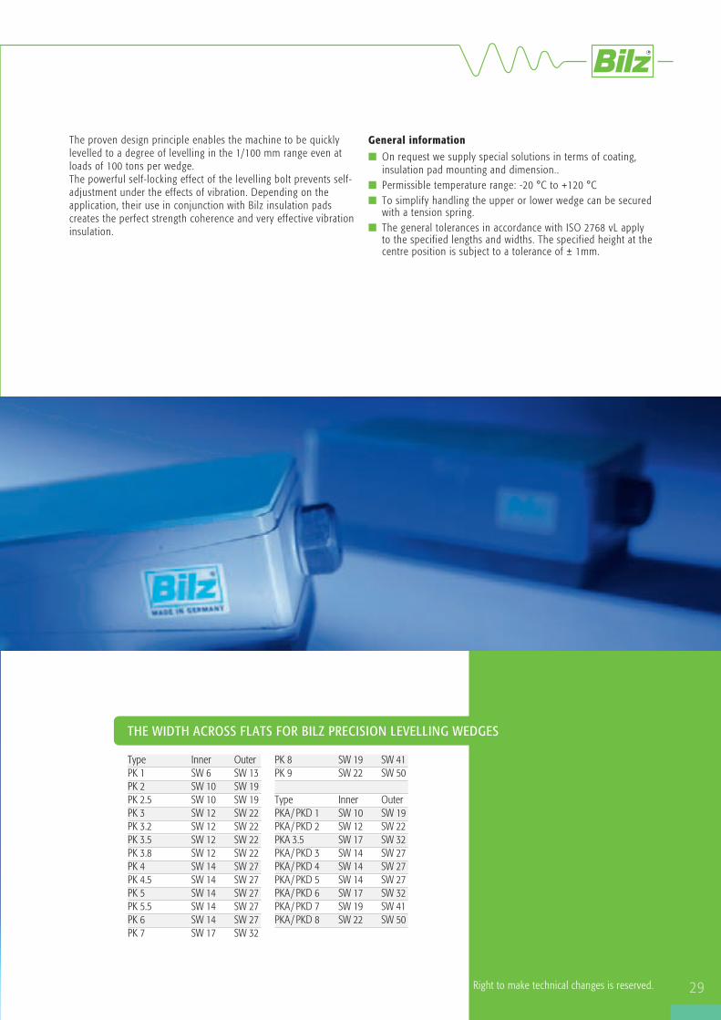
The proven design principle enables the machine to be quicklylevelled to a degree of levelling in the 1/100 mm range even atloads of 100 tons per wedge. The powerful self-locking effect of the levelling bolt prevents self-adjustment under the effects of vibration. Depending on theapplication, their use in conjunction with Bilz insulation padscreates the perfect strength coherence and very effective vibrationinsulation.
THE WIDTH ACROSS FLATS FOR BILZ PRECISION LEVELLING WEDGES
Right to make technical changes is reserved.
General information
n On request we supply special solutions in terms of coating,insulation pad mounting and dimension..
n Permissible temperature range: -20 °C to +120 °Cn To simplify handling the upper or lower wedge can be secured
with a tension spring.n The general tolerances in accordance with ISO 2768 vL apply
to the specified lengths and widths. The specified height at thecentre position is subject to a tolerance of ± 1mm.
PK 8 SW 19 SW 41PK 9 SW 22 SW 50
Type Inner OuterPKA / PKD 1 SW 10 SW 19PKA / PKD 2 SW 12 SW 22PKA 3.5 SW 17 SW 32PKA / PKD 3 SW 14 SW 27PKA / PKD 4 SW 14 SW 27PKA / PKD 5 SW 14 SW 27PKA / PKD 6 SW 17 SW 32PKA / PKD 7 SW 19 SW 41PKA / PKD 8 SW 22 SW 50
Type Inner OuterPK 1 SW 6 SW 13PK 2 SW 10 SW 19PK 2.5 SW 10 SW 19PK 3 SW 12 SW 22PK 3.2 SW 12 SW 22PK 3.5 SW 12 SW 22PK 3.8 SW 12 SW 22PK 4 SW 14 SW 27PK 4.5 SW 14 SW 27PK 5 SW 14 SW 27PK 5.5 SW 14 SW 27PK 6 SW 14 SW 27PK 7 SW 17 SW 32

30
Precision levelling wedge PK Free-standingSpecifically for machines without mounting holes in the machine bed
A-MOUNTING
B-MOUNTING
Universal application formachine tools and injec-tion moulding machines. Very good insulationeffect. Specifically formachines subject to highhorizontal forces. Veryhigh anti-slip effect!TOP FACE: Anti-slip plateBR7-1BOTTOM FACE: Insulation pad B4-1
Special design for CNClathes, grindingmachines, drilling andcutting mills, cuttingcentres, transfer lines.TOP FACE:Anti-slip plate BSBOTTOM FACE:Insulation pad B0
Note
n The specified maximum load is composed of static and dynamicloading of the machine. The best insulation effect is achieved atapproximately 80-90 % of the specified maximum load.
n Details on the properties of the insulation pads used can befound on pages 14-17.
n Please contact us if the size or insulation pad mounting thatyou are looking for is not listed. In addition to our standard solutions and colours we also carrynumerous special solutions. We are always happy to giveadvice.
Type Item no. max. load L B H Adjustment range PK Centre position N/pc. mm mm mm mmPK 1-A 02- 0004 5.400 105 55 59 +4/-5PK 2-A 02- 0011 10.000 150 75 63 +5/-6PK 2.5-A 02-0104 12.000 115 115 67 +4/-5PK 3-A 02- 0025 18.000 200 95 67 +5/-5PK 3/72-A 02- 0019 18.000 200 95 94 +5/-4PK 3.2-A 02-0110 20.000 150 150 68 +5/-6PK 3.5-A 02-0116 26.000 115 250 92 +4/-8PK 3.8-A 02-0122 26.000 170 170 76 +6/-8PK 4-A 02- 0042 38.000 200 200 70 +5/-7PK 4/72-A 02- 0033 38.000 200 200 94 +5/-7PK 4.5-A 02-0128 39.000 180 230 84 +9/-9PK 5-A 02- 0050 48.000 200 250 94 + 10/- 7PK 5.5-A 02-0134 73.000 300 250 106 +10/-8PK 6-A 02- 0057 80.000 250 330 94 + 7/-10PK 7-A 02- 0064 117.500 300 400 95 + 8/-12PK 8-A 02- 0071 195.500 400 500 95 + 8/-14PK 9-A 02- 0078 294.500 500 600 137 +12/-15
Colour: RAL 7037, dusty grey
Type Item no. max. load L B H Adjustment range PK Centre position N/pc. mm mm mm mmPK 1-B 02- 0005 10.000 105 55 54 +4/-5PK 2-B 02- 0012 21.000 150 75 58 +5/-6PK 2.5-B 02-0105 25.000 115 115 62 +4/-5PK 3-B 02- 0026 36.000 200 95 62 +5/-5PK 3/72-B 02- 0020 36.000 200 95 89 +5/-4PK 3.2-B 02-0111 43.000 150 150 63 +5/-6PK 3.5-B 02-0117 55.000 115 250 87 +4/-8PK 3.8-B 02-0123 55.000 170 170 71 +6/-8PK 4-B 02- 0043 77.000 200 200 65 +5/-7PK 4/72-B 02- 0034 77.000 200 200 89 +5/-7PK4.5-B 02-0129 79.500 180 230 79 +9/-9PK 5-B 02- 0051 97.000 200 250 89 + 10/- 7PK 5.5-B 02-0135 144.000 300 250 101 +10/-8PK 6-B 02- 0058 161.000 250 330 89 + 7/-10PK 7-B 02- 0065 236.000 300 400 90 + 8/-12PK 8-B 02- 0072 393.000 400 500 90 + 8/-14PK 9-B 02- 0079 591.000 500 600 132 +12/-15
B
L
H
Right to make technical changes is reserved.

31
C-MOUNTING
D-MOUNTING
Highly effective vibrationinsulation. Especially forinstallation on upperfloors.Please contact us incases of sensitive appli-cations.TOP FACE:Anti-slip plate BSBOTTOM FACE:Insulation pad B32
For machines with highdynamic forces such aspresses, punches, shears.TOP FACE:Anti-slip plate BR7-1BOTTOM FACE:Insulation pad B5
Type Item no. max. load L B H Adjustment range PK Centre position N/pc. mm mm mm mmPK 1-C 02- 0006 4.600 105 55 64 +4/-5PK 2-C 02- 0013 8.700 150 75 68 +5/-6PK 2.5-C 02-0106 10.000 115 115 72 +4/-5PK 3-C 02- 0027 14.600 200 95 72 +5/-5PK 3/72-C 02- 0021 14.600 200 99 99 +5/-4PK 3.2-C 02-0112 17.000 150 150 73 +5/-6PK 3.5-C 02-0118 22.000 115 250 97 +4/-8PK 3.8-C 02-0124 22.000 170 170 81 +6/-8PK 4-C 02- 0044 31.000 200 200 75 +5/-7PK 4/72-C 02- 0035 31.000 200 200 99 +5/-7PK 4.5-C 02-0133 32.000 180 230 89 +9/-9PK 5-C 02- 0052 38.900 200 250 99 + 10/- 7PK 5.5-C 02-0136 58.000 300 250 111 +10/-8PK 6-C 02- 0059 64.500 250 330 99 + 7/-10PK 7-C 02- 0066 94.500 300 400 100 + 8/-12PK 8-C 02- 0073 157.000 400 500 100 + 8/-14PK 9-C 02- 0080 236.000 500 600 142 +12/-15
Type Item no. max. load L B H Adjustment range PK Centre position N/pc. mm mm mm mmPK 1-D 02- 0007 8.700 105 55 69 +4/-5PK 2-D 02- 0014 17.000 150 75 73 +5/-6PK 2.5-D 02-0107 20.000 115 115 77 +4/-5PK 3-D 02- 0028 29.000 200 95 77 +5/-5PK 3/72-D 02- 0022 29.000 200 95 104 +5/-4PK 3.2-D 02-0113 34.500 150 150 78 +5/-6PK 3.5-D 02-0119 44.500 115 250 102 +4/-8PK 3.8-D 02-0125 44.500 170 170 86 +6/-8PK 4-D 02- 0045 62.000 200 200 80 +5/-7PK 4/72-D 02- 0036 62.000 200 200 104 +5/-7PK 4.5-D 02-0130 64.000 180 230 94 +9/-9PK 5-D 02- 0053 77.000 200 250 104 + 10/- 7PK 5.5-D 02-0137 116.000 300 250 116 +10/-8PK 6-D 02- 0060 129.000 250 330 104 + 7/-10PK 7-D 02- 0067 189.000 300 400 105 + 8/-12PK 8-D 02- 0074 314.000 400 500 105 + 8/-14PK 9-D 02- 0081 470.000 500 600 147 +12/-15

32
F-MOUNTING
For extremely high loads.Very good level consis-tency.TOP FACE:Anti-slip plate BSBOTTOM FACE:Insulation pad B6
Type Item no. max. load L B H Adjustment range PK Centre position N/pc. mm mm mm mmPK 1-F 02- 0009 19.000 105 55 54 +4/-5PK 2-F 02- 0016 38.000 150 75 58 +5/-6PK 2.5-F 02-0109 44.500 115 115 62 +4/-5PK 3-F 02- 0030 64.000 200 95 62 +5/-5PK 3/72-F 02- 0024 64.000 200 95 89 +5/-4PK3.2-F 02-0115 75.800 150 150 63 +5/-6PK3.5-F 02-0121 97.000 115 250 87 +4/-8PK3.8-F 02-0127 97.000 170 170 71 +6/-8PK 4-F 02- 0047 135.000 200 200 65 +5/-7PK 4.5-F 02-0132 139.500 180 230 79 +9/-9PK 4/72-F 02- 0039 135.000 200 200 89 +5/-7PK 5-F 02- 0055 170.000 200 250 89 + 10/- 7PK5.5-F 02-0139 253.000 300 250 101 +10/-8PK 6-F 02- 0062 282.000 250 330 89 + 7/-10PK 7-F 02- 0069 414.000 300 400 90 + 8/-12PK 8-F 02- 0076 680.000 400 500 90 + 8/-14PK 9-F 02- 0083 1.035.000 500 600 132 +12/-1
E-MOUNTING
Machines and systemsthat require no vibrationinsulation. Good frictionalengagement due toequipping with anti-slipplates. Very low overallheight. TOP FACE:Anti-slip plate BSBOTTOM FACE:Anti-slip plate BS
Type Item no. max. load L B H Adjustment range PK Centre position N/pc. mm mm mm mmPK 1-E 02- 0008 16.000 105 55 41 +4/-5PK 2-E 02- 0015 32.500 150 75 45 +5/-6PK 2.5-E 02-0108 38.000 115 115 49 +4/-5PK 3-E 02- 0029 54.900 200 95 49 +5/-5PK 3/72-E 02- 0023 54.900 200 95 76 +5/-4PK3.2-E 02-0114 65.000 150 150 50 +5/-6PK3.5-E 02-0120 83.500 115 250 74 +4/-8PK3.8-E 02-0126 83.500 170 170 58 +6/-8PK 4-E 02- 0046 116.400 200 200 52 +5/-7PK 4/72-E 02- 0037 116.400 200 200 76 +5/-7 PK 4.5-E 02-0131 120.000 180 230 66 +9/-9PK 5-E 02- 0054 145.500 200 250 76 + 10/- 7PK5.5-E 02-0138 218.000 300 250 88 +10/-8PK 6-E 02- 0061 242.000 250 330 76 + 7/-10PK 7-E 02- 0068 355.000 300 400 77 + 8/-12PK 8-E 02- 0075 589.500 400 500 77 + 8/-14PK 9-E 02- 0082 887.000 500 600 119 +12/-15
Right to make technical changes is reserved.

PKA 1-0 to PKA 8-0
Lathes, boring mills,grinding machines andmachining centres. TOP FACE:Plain surfaceBOTTOM FACE:Insulation pad BO
Type Item no. max. load L B H d e Internal thread Adjustment PKA Centre position range N/pc. mm mm mm mm mm mmPKA 1-0 03- 0007 25.000 115 115 60 50 24 M16 +3/-3PKA 2-0 03- 0010 43.000 150 150 61 58 23 M18 +4/-4PKA 3-0 03- 0024 77.000 200 200 63 76 27 M20 +4/-6PKA 3/72-0 03- 0020 77.000 200 200 87 76 27 M20 +4/-7PKA 4-0 03- 0028 97.000 200 250 87 95 27 M20 +10/-7PKA 5-0 03- 0033 161.000 250 330 87 125 105 M24 +6/-10PKA 6-0 03- 0037 236.000 300 400 88 150 95 M24 +8/-12PKA 7-0 03- 0040 393.000 400 500 88 200 130 M24 +8/-14PKA 8-0 03- 0043 591.000 500 600 130 255 150 M30 x 2 +12/-15
33
Precision levelling wedge series PKA
Bolt-on Bilz precision levelling wedges PKA are used on machinessubject to high thrust that require a permanent connection to themachine bed, such as injection moulding machines, slottingmachines, extrusion machines etc. The bolt-on levelling wedges remain in position even when themachine is lifted, significantly easing the installation of themachine.
Note
n The type of Insulation pads used can be found in the typedesignation, for example PKA 3-0 is equipped with pad B0, PKA3-4 with B4.
n The specified maximum load is composed of static and dynamicloading of the machine. The best insulation effect is achieved atapproximately 80-90 % of the specified maximum load.
n Details on the properties of the insulation pads used can befound on pages 14-17.
n Please contact us if the size, insulation pad mounting or boldsize that you are looking for is not listed. In addition to ourstandard solutions and colours we also carry numerous specialsolutions. We are always happy to give advice.
Ld
Bee
PKA 1-4 TO PKA 8-4
Plastic injection mouldingmachines, die castingmachines, plaining andslotting machines, coldextrusion machines, etc.Extreme slip resistance. TOP FACE:Plain surfaceBOTTOM FACE:Insulation pad B4
Type Item no. max. load L B H d e Internal thread Adjustment PKA Centre position range N/pc. mm mm mm mm mm mmPKA 1-4 03- 0008 12.000 115 115 60 50 24 M16 +3/-3PKA 2-4 03- 0011 20.000 150 150 61 58 23 M18 +4/-4PKA 3-4 03- 0025 38.000 200 200 63 76 27 M20 +4/-6PKA 3/72-4 03- 0022 38.000 200 200 87 76 27 M20 +4/-7PKA 4-4 03- 0030 48.000 200 250 87 95 27 M20 +10/-7PKA 5-4 03- 0034 80.000 250 330 87 125 105 M24 +6/-10PKA 6-4 03- 0038 117.500 300 400 88 150 95 M24 +8/-12PKA 7-4 03- 0041 195.500 400 500 88 200 130 M24 +8/-14PKA 8-4 03- 0044 294.500 500 600 130 255 150 M30 x 2 +12/-15
Bolts: Suitable bolts and nuts with standard thread can besupplied on request, see table 1, p. 37.
Colour: RAL 7037, dusty grey

Note
n The type of insulation pads used can be found in the typedesignation, for example PKD 3-0 is equipped with pad B0,PKD 3-4 with B4.
n The specified maximum load is composed of static and dynamicloading of the machine. The best insulation effect is achieved atapproximately 80-90 % of the specified maximum load.
n Details on the properties of the insulation pads used can befound on pages 14-17.
n Please contact us if the size, insulation pad mounting or boldsize that you are looking for is not listed. In addition to ourstandard solutions and colours we also carry numerous specialsolutions. We are always happy to give advice.
n Supply is inclusive of an appropriate insulating washer toinsulate the bolt head.
34
Bolt-through Bilz precision levelling wedge PKD are used onmachines that necessarily need to be anchored due tounfavourable centre of gravity proportions. Also for machines thatmust be pushed or pulled when levelling – and for machines withlow intrinsic rigidity.
PKD 1-0 TO PKD 8-0
Boring and cutting mills,machining centres,special machines, longbed lathers, long bedplaining machines.TOP FACE:Plain surfaceBOTTOM FACE: Insulation pad B0
Type Item no. max. load L B H d e Drill hole Adjustment range PK Centre position N/pc. mm mm mm mm mm mmPKD 1-0 04- 0003 25.000 115 115 60 50 24 22 +4/-5PKD 2-0 04- 0005 43.000 150 150 61 58 23 23 +5/-6PKD 3-0 04- 0009 77.000 200 200 63 76 27 26 +3/-7PKD 3/72-0 04- 0007 77.000 200 200 87 76 27 26 +4/-7PKD 4-0 04- 0011 97.000 200 250 87 95 27 26 +10/-7PKD 5-0 04- 0013 161.000 250 330 87 125 105 30 +6/-10PKD 6-0 04- 0015 236.000 300 400 88 150 95 30 +8/-12PKD 7-0 04- 0017 393.000 400 500 88 200 130 35 +8/-14PKD 8-0 04- 0019 591.000 500 600 130 255 150 35 +12/-15
Precision levelling wedge series PKD
Ld
Bolts: Suitable bolts and nuts with standard thread and anchorfor floor anchoring can be supplied on request, see p. 37/38.
Colour: RAL 7037, dusty grey

Note
n The type of insulation pads used can be found in the typedesignation, for example PKD 3-0 is equipped with PKD 3-4with B4.
n The specified maximum load is composed of static and dynamicloading of the machine. The best insulation effect is achieved atapproximately 80-90 % of the specified maximum load.
n Details on the properties of the insulation pads used can befound on pages 14-17.
n Please contact us if the size, insulation pad mounting or boldsize that you are looking for is not listed. In addition to ourstandard solutions and colours we also carry numerous specialsolutions. We are always happy to give advice.
n For type PKDK supply is inclusive of an appropriate insulatingwasher to insulate the bolt head.
35
Precision levelling wedge with spherical seat Series PKAK / PKDKBilz precision levelling wedge PKAK (bolt-on)/ PKDK (bolt-through) with spherical seat to compensate for angle differencesbetween machines and foundations, e.g. non processed machinemounts or uneven floors. Specifically for machines with a longbed and higher demands on geometry.
PKAK / PKDK 1-0 TO PKAK / PKDK 4-0 WITH SPHERICAL SEAT
TOP FACE SPHERICALSEAT: PaintedBOTTOM FACE:Insulation pad B0
Type Item no. max. load L B H O/ D d e Internal Adjustment PK Centre position thread range N/pc. mm mm mm mm mm mm mmPKAK 1-0 05- 0003 25.000 115 115 70 110 50 24 M16 +3/-3PKAK 2-0 05- 0008 43.000 150 150 77 150 58 23 M18 +4/-4PKAK 3-0 05- 0011 77.000 200 200 79 150 76 27 M20 +4/-6PKAK 4-0 05- 0015 97.000 200 250 103 150 95 27 M20 +10/-7 Drill hole
mmPKDK 1-0 06- 0003 25.000 115 115 70 110 50 24 22 +4/-5PKDK 2-0 06- 0006 43.000 150 150 77 150 58 23 23 +5/-6PKDK 3-0 06- 0008 77.000 200 200 79 150 76 26 26 +3/-7PKDK 4-0 06- 0010 97.000 200 250 103 150 95 27 26 +10/-7
Bolts: Suitable bolts and nuts with standard thread and anchorfor floor anchoring (only PKDK) can be supplied on request,see p. 37/38.
Colour: RAL 7037, dusty grey
B
Ø D±3°
e
e
dL
Right to make technical changes is reserved.

Type Item no. max. load L B H d e Internal Adjustment PKA-AL Centre position thread range N/pc. mm mm mm mm mm mmPKA 1-AL 03-0060 19.000 115 115 44 50 24 M16 +3/-3PKA 2-AL 03-0061 32.000 150 150 47 60 24 M18 +3/-5PKA 3-AL 03-0062 57.000 200 200 53 80 27 M20 +4/-5PKA 4-AL 03-0063 72.000 200 250 73 95 27 M20 +9/-5 Item no. Drill hole PKD-AL mmPKD 1-AL 04-0020 19.000 115 115 44 50 24 22 +3/-3PKD 2-AL 04-0021 32.000 150 150 47 60 24 22 +3/-5PKD 3-AL 04-0022 57.000 200 200 53 80 27 26 +4/-5PKD 4-AL 04-0023 72.000 200 250 73 95 27 26 +9/-5
Type Item no. max. load L B H O/ D d e Internal Adjustment PKAK-AL Centre position thread range N/pc. mm mm mm mm mm mm mmPKAK 1-AL 05-0018 19.000 115 115 54 110 50 24 M16 +3/-3PKAK 2-AL 05-0019 32.000 150 150 63 150 60 24 M18 +3/-5PKAK 3-AL 05-0020 57.000 200 200 69 150 80 27 M20 +4/-5PKAK 4-AL 05-0021 72.000 200 250 89 150 95 27 M20 +9/-5 Item no. Drill hole PKDK-AL mmPKDK 1-AL 06-0012 19.000 115 115 54 110 50 24 22 +3/-3PKDK 2-AL 06-0013 32.000 150 150 63 150 60 24 22 +3/-5PKDK 3-AL 06-0014 57.000 200 200 69 150 80 27 26 +4/-5PKDK 4-AL 06-0015 72.000 200 250 89 150 95 27 26 +9/-5
36
Precision levelling wedge PKA(K)-AL / PKD(K)-ALAluminium designs of the series bolt-on and bolt-through
Bilz precision levelling wedges in aluminium design hardanodised (hard coating) are distinguished by their very high layerdensity, high degree of hardness – up to 600 HV and very goodwear properties. The levelling wedge is easy to adjust and particu-larly suitable for EMV applications.
Bolts: Suitable bolts and nuts with standard thread and anchorfor floor anchoring (only PKD-AL and PKDK-AL) can be suppliedon request, see p. 37/38.Colour: Natural colour dark grey
PKA(K)-AL AND PKD(K)-AL
Machines for the foodand luxury food indus-tries, machines for thepackaging, chemical andpharmaceutical indus-tries. We also offerspecial solutions withoutlubricant and for higherloads for applications inclean rooms.
Right to make technical changes is reserved.
Note
n All sizes can be supplied with a stainless steel spherical seat.
n The specified maximum load is composed of static and dynamicloading of the machine.
n Mounting with Bilz insulation pads is also possible (also inEPDM or clean room applications).
n Please contact us if the size, insulation pad mounting or boldsize that you are looking for is not listed. In addition to ourstandard solutions and colours we also carry numerous specialsolutions. We are always happy to give advice.
n General tolerances in accordance with ISO 2768 mK.
B
Ø D±3°
e
e
dL
37
Structure bornenoise insulation inrigidly anchoredmachines andpipe suspensions.
INSULATION WASHERS TO INSULATE THE BOLT HEAD
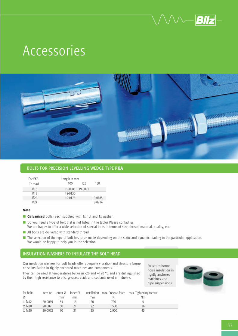
Accessories
Our insulation washers for bolt heads offer adequate vibration and structure bornenoise insulation in rigidly anchored machines and components.
They can be used at temperatures between -20 and +120 °C and are distinguishedby their high resistance to oils, greases, acids and coolants used in industry.
for bolts Item no. outer Ø inner Ø Installation max. Preload force max. Tightening torque Ø mm mm mm N Nm to M12 20-0069 35 13 20 790 5 to M20 20-0071 50 21 22 1.500 16 to M30 20-0072 70 31 25 2.900 45
BOLTS FOR PRECISION LEVELLING WEDGE TYPE PKA
For PKA Length in mm 100 125 150
M16 19-0085 19-0091 M18 19-0130 M20 19-0178 19-0185 M24 19-0214
Thread
Note
n Galvanised bolts; each supplied with 1x nut and 1x washer.
n Do you need a type of bolt that is not listed in the table? Please contact us. We are happy to offer a wide selection of special bolts in terms of size, thread, material, quality, etc.
n All bolts are delivered with standard thread.
n The selection of the type of bolt has to be made depending on the static and dynamic loading in the particular application. We would be happy to help you in the selection.

HORIZONTAL ELEMENTS
EXTENSION FOR LEVELLING WEDGE BOLTS
Size 1Steel angle, Levelling element Type BNVS 115/5, 3 bolts M16 x 150, 2 anchors M16
Size 2Steel angle, Levelling elementType BNVS 115/5, 4 bolts M20 x 150, 3 anchors M20
38
Type Item no. max. a b c d e f g i load N/pc. mm mm mm mm mm mm mm mmSize 1 20-0066 16.500 140 125 45 60 -115 50 25 35 17.5Size 2 20-0067 16.500 160 180 55 60 -140 48 43 37 22
Extension for levelling wedge bolts
We recommend the use of the levelling bolt extension for difficult to access levelling boltsThis facilitates the quick and easy levelling of the machine even where space is limited.
These levelling aids are available if different lengths and width across flats depending on thelevelling wedge being used. Please contact us for further details.
ANCHOR FOR FLOOR ANCHORING
Fischer heavy dutyanchor SL
Fisher reactionanchor R andthreaded rod RG
Fischer anchor bolt FAZ
Our supply range includes Fischer anchors.Other types and manufacturers are available on request.
Right to make technical changes is reserved.
Size 1
Size 2

FAEBI®
Rubber air spring insulatorHighly effective insulation of vibrations, shocks and structure borne noise for machines, apparatus and aggregates.
39
0
2
4
6
8
10
12
14
500 1000 1500 2000 2500 3000
VVeerrttii
kkaallee
EEiigg
eennffrree
qquueenn
zz [[HHzz
]]
LLaasstt [[NN]]
FFAAEEBBII 110000
Standard
Standard + BR-7
Soft
Soft + BR-7
Super Soft
Super Soft + BR-7
0
2
4
6
8
10
12
14
16
2000 3500 5000 6500 8000
VVeerrttii
kkaallee
EEiigg
eennffrree
qquueenn
zz [[HHzz
]]
LLaasstt [[NN]]
FFAAEEBBII 115500
Hart
Standard
Soft
Super Soft
0
1
2
3
4
5
6
7
8
10000 15000 20000 25000 30000
VVeerrttii
kkaallee
EEiigg
eennffrree
qquueenn
zz [[HHzz
]]
LLaasstt [[NN]]
FFAAEEBBII 330000
Hart
Standard
Soft
0123456789
50000 65000 80000 95000 110000 125000
VVeerrttii
kkaallee
EEiigg
eennffrree
qquueenn
zz [[HHzz
]]
LLaasstt [[NN]]
FFAAEEBBII 558800
Super Hart
Hart
Standard
0123456789
10
25000 35000 45000 55000 65000
Verti
kale
Eig
enfre
quen
z [Hz
]
Last [N]
FFAAEEBBII 443300
Hart
Standard
0
2
4
6
8
10
12
4500 7000 9500 12000 14500
VVeerrttii
kkaallee
EEiigg
eennffrree
qquueenn
zz [[HHzz
]]
LLaasstt [[NN]]
FFAAEEBBII 220000
Hart
Standard
Soft
Super Soft
0
2
4
6
8
10
12
14
2000 2500 3000 3500 4000 4500
VVeerrttii
kkaallee
EEiigg
eennffrree
qquueenn
zz [[HHzz
]]
LLaasstt [[NN]]
FFAAEEBBII 112255
Standard
Standard + BR-7
Soft
Soft + BR-7
Super Soft
Super Soft + BR-7
40
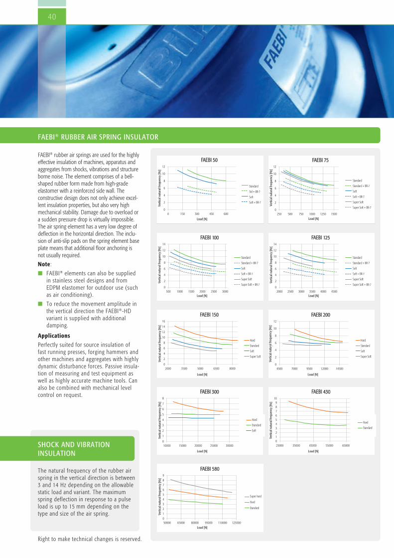
FAEBI® rubber air springs are used for the highlyeffective insulation of machines, apparatus andaggregates from shocks, vibrations and structureborne noise. The element comprises of a bell-shaped rubber form made from high-gradeelastomer with a reinforced side wall. Theconstructive design does not only achieve excel-lent insulation properties, but also very highmechanical stability. Damage due to overload ora sudden pressure drop is virtually impossible.The air spring element has a very low degree ofdeflection in the horizontal direction. The inclu-sion of anti-slip pads on the spring element baseplate means that additional floor anchoring isnot usually required.
Note:
n FAEBI® elements can also be suppliedin stainless steel designs and fromEDPM elastomer for outdoor use (suchas air conditioning).
n To reduce the movement amplitude inthe vertical direction the FAEBI®-HDvariant is supplied with additionaldamping.
Applications
Perfectly suited for source insulation offast running presses, forging hammers andother machines and aggregates with highlydynamic disturbance forces. Passive insula-tion of measuring and test equipment aswell as highly accurate machine tools. Canalso be combined with mechanical levelcontrol on request.
SHOCK AND VIBRATION INSULATION
The natural frequency of the rubber airspring in the vertical direction is between3 and 14 Hz depending on the allowablestatic load and variant. The maximumspring deflection in response to a pulseload is up to 15 mm depending on thetype and size of the air spring.
FAEBI® RUBBER AIR SPRING INSULATOR
Right to make technical changes is reserved.
0
2
4
6
8
10
12
0 150 300 450 600
VVeerrttii
kkaallee
EEiigg
eennffrree
qquueenn
zz [[HHzz
]]
LLaasstt [[NN]]
FFAAEEBBII 5500
Standard
Std + BR-7
Soft
Soft + BR-7
0
2
4
6
8
10
12
250 500 750 1000 1250 1500
VVeerrttii
kkaallee
EEiigg
eennffrree
qquueenn
zz [[HHzz
]]
LLaasstt [[NN]]
FFAAEEBBII 7755
Standard
Standard + BR-7
Soft
Soft + BR-7
Super Soft
Super Soft + BR-7
Super hard
Hard
Standard
Vertical natural frequency [Hz]
Load [N]
Hard
Standard
Soft
Vertical natural frequency [Hz]
Load [N]
Hard
Standard
Soft
Super Soft
Vertical natural frequency [Hz]
Load [N]
Hard
Standard
Soft
Super Soft
Vertical natural frequency [Hz]
Load [N]
Standard
Standard + BR-7
Soft
Soft + BR-7
Super Soft
Super Soft + BR-7
Vertical natural frequency [Hz]
Load [N]
Standard
Standard + BR-7
Soft
Soft + BR-7
Super Soft
Super Soft + BR-7
Vertical natural frequency [Hz]
Load [N]
Standard
Standard + BR-7
Soft
Soft + BR-7
Super Soft
Super Soft + BR-7
Vertical natural frequency [Hz]
Load [N]
Standard
Std + BR-7
Soft
Soft + BR-7
Vertical natural frequency [Hz]
Load [N]
Hard
Standard
Vertical natural frequency [Hz]
Load [N]

A
G
41
SERIES TYPE FAEBI®
Type Variant Item no. Load max.Pressure A ØD H approx. mm H (deflated) Ød h G FAEBI® N/pc. bar mm mm = Working height mm mm mm mmFAEBI® 50 Standard 40-0071 200–600 3 110 80 60 61 35 5 M10 Standard + BR7-1 40-0134 200–500 2.5 110 80 62 68 35 5 M10 Soft 40-0072 100–500 2.5 110 80 60 61 35 5 M10 Soft + BR7-1 40-0135 100–450 2.3 110 80 62 68 35 5 M10FAEBI® 75 Standard 40-0082 400–1.500 3 115 97 63 67 43 5 M12 Standard + BR7-1 40-0136 400–1.350 2.7 115 97 65 74 43 5 M12 Soft 40-0084 350–1.300 2.6 115 97 63 67 43 5 M12 Soft + BR7-1 40-0137 350–1.200 2.4 115 97 65 74 43 5 M12 Super Soft 40-0083 300–1.050 2.1 115 97 63 67 43 5 M12 Super Soft + BR7-1 40-0138 300–1.050 2.1 115 97 65 74 43 5 M12FAEBI® 100 Standard 40-0024 750–3.000 5 135 118 62 65 60 5 M12 Standard + BR7-1 40-0139 750–3.000 5 135 118 64 72 60 5 M12 Soft 40-0026 600–2.600 4.4 135 118 62 65 60 5 M12 Soft + BR7-1 40-0140 600–2.600 4.4 135 118 64 72 60 5 M12 Super Soft 40-0025 550–2.400 4 135 118 62 65 60 5 M12 Super Soft + BR7-1 40-0141 550–2.400 4 135 118 64 72 60 5 M12FAEBI® 125 Standard 40-0033 2.600–4.600 5.5 165 140 93 98 66 5 M16 Standard + BR7-1 40-0142 2.600–4.600 5.5 165 140 95 105 66 5 M16 Soft 40-0035 2.400–4.050 4.9 165 140 93 98 66 5 M16 Soft + BR7-1 40-0143 2.400–4.050 4.9 165 140 95 105 66 5 M16 Super Soft 40-0034 2.200–3.500 4.2 165 140 93 98 66 5 M16 Super Soft + BR7-1 40-0144 2.200–3.500 4.2 165 140 95 105 66 5 M16FAEBI® 150 Hart 40-0043 2.600–8.500 6.4 200 170 91 96 80 8 M16 Standard 40-0037 2.500–8.000 6 200 170 91 96 80 8 M16 Soft 40-0040 2.400–7.000 5.3 200 170 91 96 80 8 M16 Super Soft 40-0038 2.300–6.500 4.9 200 170 91 96 80 8 M16FAEBI® 200 Hart 40-0051 7.000–15.000 6 260 236 91 95 130 8 M16 Standard 40-0046 6.250–15.000 6 260 236 91 95 130 8 M16 Soft 40-0048 6.000–13.000 5.2 260 236 91 95 130 8 M16 Super Soft 40-0047 5.500–11.500 4.6 260 236 91 95 130 8 M16FAEBI® 300 Hart 40-0058 12.000–28.000 6.5 370 340 89 93 200 8 M20 Standard 40-0055 11.500–27.000 6 370 340 89 93 200 8 M20 Soft 40-0056 10.500–25.000 5.6 370 340 89 93 200 8 M20FAEBI® 430 Hart 40-0065 30.000–66.000 6.1 500 480 89 94 315 8 M20 Standard 40-0064 27.500–65.000 6 500 480 89 94 315 8 M20FAEBI® 580 Super Hart 40-0079 54.000–120.000 6.6 680 650 89 91 380 14 M24 Hart 40-0078 52.000–115.000 6.3 680 650 89 91 380 14 M24 Standard 40-0076 51.500–110.000 6 680 650 89 91 380 14 M24
Note
n Ensure that the element is selected so that the maximum load (staticand dynamic load) is not exceeded! For applications with higher dynamics harder variants of the FAEBI®
reduce the deflection of the element. However, the softer theelement is, the better the achievable insulation effect is. Please contact us, we are happy to assist with selecting a suitableelement.
n If the bottom edge of the machine does not completely cover Ø d,we recommend the use of our special protective hood (see Acces-sories p. 46).
n Permissible temperature range: -20 °C to +80 °C
n The elements are attached to the holes provided on the machine using the bolts supplied (see Accessories p. 46).Anchoring to the floor is usually not necessary.
n Screw in the bolt by hand only, do not use a wrench. Also only tighten the nut with low torque.
n The machine is placed on the deflated element, which is then inflated in stages using the standard valve until dimension H(= working height) is reached. The maximum specified air pressure must also not be exceeded!
n Inflation and deflation may only take place under load (observe the maximum permissible pressure).
n Up to +/- 5 mm are available for levelling.
Right to make technical changes is reserved.

42
ADVANTAGES COMPARED TO STEEL SPRINGS
In comparison to steel springs the use of air spring offers manyadvantages when used for vibration insulation:
n Flexible insulation system design: Changes in the static or dynamic loads can be compensated
for by adjusting the air pressure. This can be performed eithermanually or pneumatically (e.g. using Bilz level control)
n Integrated damping, therefore separate damping is not necessary.
n No transmission of structure borne noise
FAEBI® in stainless steel and EPDM-versionfor outside applications
FAEBI® elements in VA and EPDM versions were specifically developed for outside applications. Effortless vibration insulation of systems in the open air such as airconditioning units, compressors, heat exchangers, cold water chillers.
Note:
n Permissible temperature range: -25 °C to +125 °C
n Prices and delivery times on request.
n In addition to our standard solutions listed here we also carrynumerous special solutions. Please contact us, we would behappy to advise you.
n The use of a stainless steel protective hood is recommended foroutside applications.

Type series FAEBI®-HD with adjustable damping
The combined rubber-air spring insulator FAEBI®-HD withadjustable damping comprises of an elastomer metal bonding withreinforced side wall and a two-chamber system. To achieve the greatest possible damping effect the interior of theair spring is divided into two air chambers connected by an airhose (load and damping volume). An adjustable throttle valve isused to set the flow cross section to the desired damping effectfrom the outside. The significantly higher damping effectcompared to a single chamber system (FAEBI®) reduces theresonance amplification substantially and the machine movementsfade noticeably faster. The increased energy substancially absorp-tion also has a positive effect on the manufactured goods and onmachine and tool wear.
Benefits: In comparison to viscous damping air damping isabsolutely free of wear and maintenance-free and the dampingfactor can be easily adjusted from outside.
Note
n Ensure that the element is selected so that the maximum load(static and dynamic load) is not exceeded! For applicationswith higher dynamics harder variants of the FAEBI® reduce thedeflection of the element. However, the softer the element is,the better the achievable insulation effect is. Please contactus, we are happy to assist with selecting a suitable element.
n If the bottom edge of the machine does not completely coverØ d, we recommend the use of our special protective hood(see Accessories p. 46).
n Permissible temperature range: -20 °C to +80 °C
n The elements are attached to the holes provided on themachine using the bolts supplied (see p. 46). Anchoring tothe floor is usually not necessary.
n Screw in the bolt by hand only, do not use an open-endwrench. Also only tighten the nut with low torque.
n The machine is placed on the deflated element, which is theninflated in stages using the standard valve until dimension H(= working height) is reached. The maximum specified airpressure must also not be exceeded!
n Inflation and deflation may only take place under load,observe the maximum permissible pressure.
n Up to +/- 5 mm are available for levelling.
SETTLING BEHAVIOUR FAEBI® SETTLING BEHAVIOUR FAEBI®-HD
Without adjustable damping (single chamber system) With adjustable damping (twin chamber system)
Time in seconds
FAEBI® without adjustable damping
Vibr
atio
n ac
cele
ratio
n in
G
0.1
0.08
0.06
0.04
0.02
0
-0.02
-0.04
-0.06
-0.08
-0.1
0.5 1 1.5 2 1.5 2
Time in seconds
FAEBI® with adjustable damping
Vibr
atio
n ac
cele
ratio
n in
G
0.1
0.08
0.06
0.04
0.02
0
-0.02
-0.04
-0.06
-0.08
-0.1
2 0.5 1 1.5 2
43

F
44
FAEBI®-HD
Type Variant Item no. Load max.Pressure A Ø D H approx. mm = H (deflated) Ø d h G N/pc. bar mm mm Working height mm mm mm mmFAEBI® 200-HD Hart 40-0054 7.000 –15.000 6 260 236 89 90 130 8 M16 Standard 40-0053 6.250 –15.000 6 260 236 89 90 130 8 M16FAEBI® 300-HD Hart 40-0063 14.000 – 29.500 6.5 370 340 89 94 200 8 M20 Standard 40-0061 11.500 – 27.000 6 370 340 89 93 200 8 M20FAEBI® 430-HD Hart 40-0070 30.000 – 66.000 6.1 500 480 91 97 315 8 M20 Standard 40-0067 27.500 – 65.000 6 500 480 91 96 315 8 M20FAEBI® 580-HD Super Hart 40-0081 60.000 – 115.000 6.9 680 650 126 135 380 14 M24 Hart 40-0145 56.000 – 108.000 6.5 680 650 126 133 380 14 M24 Standard 40-0080 47.000 – 100.000 6 680 650 126 130 380 14 M24
NATURAL FREQUENCIES FAEBI® 200-HD TO 580-HD
FAEBI® 200-HD
02468
1012141618
5000 7000 9000 11000 13000 15000 17000
VVeerrttii
kkaallee
EEiigg
eennffrree
qquueenn
zz [[HHzz
]]
LLaasstt [[NN]]
FFAAEEBBII 220000--HHDD
0
2
4
6
8
10
12
14
16
10000 15000 20000 25000 30000
VVeerrttii
kkaallee
EEiigg
eennffrree
qquueenn
zz [[HHzz
]]
LLaasstt [[NN]]
FFAAEEBBII 330000--HHDD
0
2
4
6
8
10
12
14
16
25000 35000 45000 55000 65000
VVeerrttii
kkaallee
EEiigg
eennffrree
qquueenn
zz [[HHzz
]]
LLaasstt [[NN]]
FFAAEEBBII 443300--HHDD
0
1
2
3
4
5
6
7
8
45000 60000 75000 90000 105000 120000
VVeerrttii
kkaallee
EEiigg
eennffrree
qquueenn
zz [[HHzz
]]
LLaasstt [[NN]]
FFAAEEBBII 558800--HHDD
Super Hart
H
Hart
S
Standard
FAEBI® 300-HD FAEBI® 430-HD FAEBI® 580-HD
Right to make technical changes is reserved.
Bypass for adjustabledamping
Fillingvalve Top chamber
Bottom chamber
Vertical natural frequency [Hz]
Load [N]
Vertical natural frequency [Hz]
Load [N]
Vertical natural frequency [Hz]
Load [N]
Vertical natural frequency [Hz]
Load [N]

The mechanical-pneumatic level control (MPN) with our robustproportional valve LVC represents a simple but effective solutionfor preventing skew positions resulting from load changes. Aplunger continuously probes the level and the position of theplunger is transmitted to a slide valve. The air spring is eitherpressurized or the internal pressure is vented in accordance withthe position of the plunger. The adjustable target level ismaintained within an accuracy of ± 1/10 mm. In principle three control valves are used, that optionally have anupstream air maintenance unit for conditioning the pneumatic airsupply, limiting the system pressure to 6 bar, removing accumu-lated condensate and filtering out solid particles (rust and dust).
For further details see the catalogue page 52.
The Bilz pressure control is the ideal addition to applications thatdoes not need automatic level control.
Instead of filling the air springs manually, they are connected to aconstant compressed air supply. The working height of theindividual insulators can each be individually set with onepressure regulator.
Applications
n Applications with a constant centre of gravity during theproduction/testing process (no moving machine components,workpieces, etc., steady masses).
n Difficult to access systems, where the manual checking of airpressure in the air springs is impeded.
Advantages of FAEBI® pressure control
n Simple and precise setting of the required pressure for eachair spring or control group.
n Maintenance free
n Manometer for continuous pressure indication
n Upstream particle filter and water trap
n Can be configured for any number of air springs or controlgroups
FAEBI® MPN-LCV
PRESSURE CONTROL FOR FAEBI® AND FAEBI®-HD
FAEBI® AND FAEBI®-HDwith mechanical-pneumaticlevel control (MPN-LCV)
Air maintenance unit Compressed air supply(max. 10 bar)
Control valve
Air spring
45
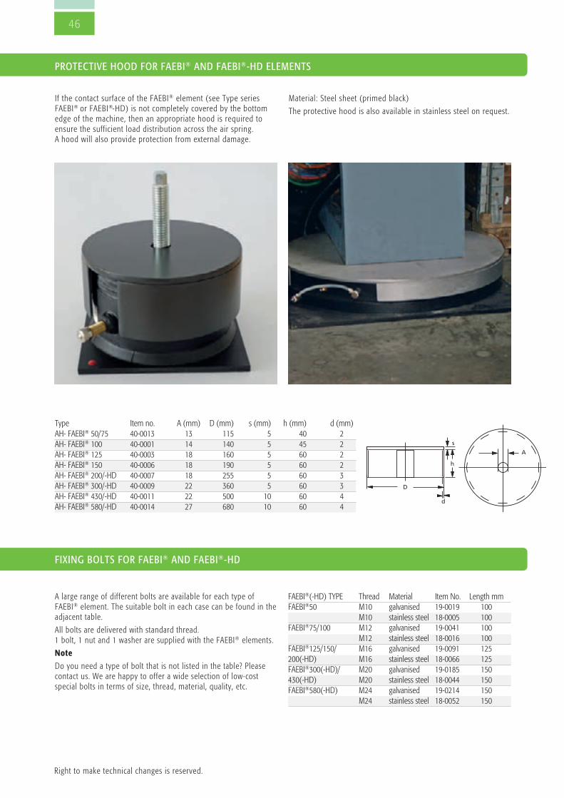
46
Right to make technical changes is reserved.
FIXING BOLTS FOR FAEBI® AND FAEBI®-HD
If the contact surface of the FAEBI® element (see Type seriesFAEBI® or FAEBI®-HD) is not completely covered by the bottomedge of the machine, then an appropriate hood is required toensure the sufficient load distribution across the air spring.A hood will also provide protection from external damage.
A large range of different bolts are available for each type ofFAEBI® element. The suitable bolt in each case can be found in theadjacent table.
All bolts are delivered with standard thread. 1 bolt, 1 nut and 1 washer are supplied with the FAEBI® elements.
Note
Do you need a type of bolt that is not listed in the table? Pleasecontact us. We are happy to offer a wide selection of low-costspecial bolts in terms of size, thread, material, quality, etc.
Type Item no. A (mm) D (mm) s (mm) h (mm) d (mm)AH- FAEBI® 50/75 40-0013 13 115 5 40 2AH- FAEBI® 100 40-0001 14 140 5 45 2AH- FAEBI® 125 40-0003 18 160 5 60 2AH- FAEBI® 150 40-0006 18 190 5 60 2AH- FAEBI® 200/-HD 40-0007 18 255 5 60 3AH- FAEBI® 300/-HD 40-0009 22 360 5 60 3AH- FAEBI® 430/-HD 40-0011 22 500 10 60 4AH- FAEBI® 580/-HD 40-0014 27 680 10 60 4
A
D
d
s
h
Material: Steel sheet (primed black)
The protective hood is also available in stainless steel on request.
FAEBI®(-HD) TYPE Thread Material Item No. Length mmFAEBI®50 M10 galvanised 19-0019 100 M10 stainless steel 18-0005 100FAEBI®75/100 M12 galvanised 19-0041 100 M12 stainless steel 18-0016 100FAEBI®125/150/ M16 galvanised 19-0091 125200(-HD) M16 stainless steel 18-0066 125FAEBI®300(-HD)/ M20 galvanised 19-0185 150 430(-HD) M20 stainless steel 18-0044 150FAEBI®580(-HD) M24 galvanised 19-0214 150 M24 stainless steel 18-0052 150
PROTECTIVE HOOD FOR FAEBI® AND FAEBI®-HD ELEMENTS

47
BiAir®
Membrane air spring insulatorLow-frequency Bilz BiAir® membrane air spring with precisely adjustable damping foreffective vibration insulation of sensitive measurement and testing equipment, precisefinishing machines, laser equipment and optical and electronic instruments as well asvehicle, engine and gearbox test beds, etc.

48
n Highly effective vibration insulation of
n sensitive measurement and testing equipment,
n precise finishing machines,
n laser equipment as well as optical and electronic instruments.
n Vibration insulated bearings for vehicle, engine andgearbox test beds
n Foundation insulation
Advantages compared to conventional steel springsThe use of Bilz BiAir® air spring insulators with active levelcontrol constantly maintains the correct level of machines orfoundations. The level control and adjustment is completelyautomatic! The pressure in the air springs is appropriately adjusted by in-or deflating in response to load changes. This keeps theinsulating effect constant in every case. Unlike steel springs air springs do not transmit structure-bornesound.
The BiAir® membrane air spring insulator is made of turned orcast aluminium. The air space is enclosed by thin-walled flexibleand pressure-resistant rolling membrane. A piston sits on top ofthe membrane and is pressed into the air space.
This design allows a highly-effective insulation against vibration. Inorder to simultaneously achieve a high degree of damping, the airspace within the insulator is divided into two chambers connectedwith an air tube (load/damping volume). An adjustable throttlevalve is used to set the flow cross section to the desired dampingeffect from the outside. The friction in the air flow generated bythe throttle valve can create a damping effect of up to 15 %.
Damage to the rolling membrane due to overpressure is virtuallyexcluded through the use of additional safety valves or a mechan-ical piston stroke limit.
With/without insulation
BiAir® MEMBRANE AIR SPRING INSULATOR WITH ADJUSTABLE DAMPING
Frequency [Hz]
Without insulation
With insulation
a in [mm/s
2]

49
Note:
n BiAir® membrane air springs are available in the following materials depending on size
n BiAir®-ED: Cast aluminium, powder coatedRAL similar to 7037 dusty grey
n BiAir®-ED-AL: Aluminium (naturally anodized)
n with a nose for mounting valves (MPN) or displacement sensors are available with the hose connection on the left (NL) or on the right (NR).
TYPE SERIES BiAir®-ED-AL IN ANODIZED ALUMINIUM
TYPE SERIES BiAir®-ED/-HE/-HE-MAX IN CAST ALUMINIUM
* Natural frequency vertical approximately 3.0 Hz, horizontal approximately 3.5 Hz** When selecting the size of air spring please select an air pressure of 4 bar.
* For the sizes 1 to 3 of series ED/HE-MAX the ØA is the same as ØC (piston diameter)
** When selecting the size of air spring please select an air pressure of 4 bar.
Aluminium BiAir®-ED-AL A B C Working height H
+/- travel
max. load N**
at an air pressure ofType without lug NR NL mm mm mm mm 4 bar 6 bar0.125* 50-0002 - - 76 72 72 77 +/-2.0 390 5800.15* 50-0005 - - 76 72 72 77 +/-2.0 670 1.0000.25* 50-0129 50-0135 50-0136 120 182 110 87 +/-2.5 1.130 1.7000.5 50-0130 50-0137 50-0138 130 198 129 100 +/-2.5 2.670 4.0001 50-0131 50-0139 50-0140 200 275 200 100 +/-3.5 6.330 9.5001.5 50-0146 50-0147 50-0148 230 305 230 100 +/-3.5 10.170 15.2602 50-0133 50-0141 50-0144 260 350 260 100 +/-2.5 14.200 21.3002.5 50-0134 50-0142 50-0143 300 390 300 100 +/-3.0 19.670 29.500
Item no. ØA B ØC Working height H in mm +/-travel
max. load N**
at an air pressure of
Type BiAir®-ED BiAir®-ED/HE BiAir®-ED/HE-MAX mm mm mm BiAir®-ED ED/HE ED/
HE-MAX mm 4 bar 6 bar
0.5 50-0012 50-0145 - 120 216 129 157 307 - +/- 2.5 2.670 4.0001 50-0026 50-0027 50-0035 172* 288 200 157 307 509 +/- 2.5 6.330 9.5001.5 50-0020 50-0021 50-0025 212* 305 230 157 307 509 +/- 3.5 10.170 15.2602 50-0045 50-0046 50-0054 226* 335 260 157 307 509 +/- 2.5 14.200 21.3002.5 50-0036 50-0037 50-0044 271* 378 300 157 307 509 +/- 3.0 19.670 29.5003 50-0055 50-0056 50-0062 348* 467 382 157 307 509 +/- 2.5 34.130 51.2004 50-0064 50-0065 50-0066 490 605 530 157 307 509 +/- 2.75 65.730 98.6005 50-0072 - 50-0073 747 875 798 157 - 509 +/- 3.5 155.730 233.600
Intermediate plate
Load volume
Damping volume
Membrane
Nose
Transport protection
Position sensor/control valve
Throttle valve for adjustable damping
Natural frequency vertical approximately 2.5 Hz, horizontal approximately 2.8 Hz.
Natural frequencies vertical BiAir®-ED approx. 2.5 HzBiAir®-ED-HE approx. 1.7 HzBiAir®-ED-HE-MAX approx. 1.2 Hz
Natural frequencies horizontal BiAir®-ED approx. 2.8 HzBiAir®-ED-HE approx. 2.8 HzBiAir®-ED-HE-MAX approx. 2.8 Hz
Note
n The maximum permissible movement amplitude in the horizontal plane is between approximately 1 to 2 mm depending on the sizeof the air spring.
n In addition to the standard solutions listed here we also offer numerous air springs with a larger stroke and lower naturalfrequency.
n Powder coated air springs are also available in other RAL colours on request.
n Permissible temperature range: -20 °C to +80 °C
n If you have any questions please contact us, we would be happy to advise you.
Right to make technical changes is reserved.
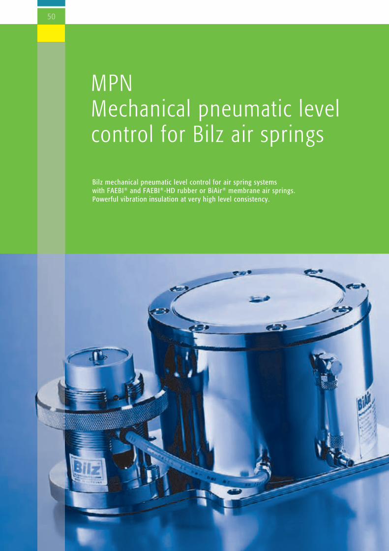
50
MPN Mechanical pneumatic levelcontrol for Bilz air springs
Bilz mechanical pneumatic level control for air spring systems with FAEBI® and FAEBI®-HD rubber or BiAir® membrane air springs.Powerful vibration insulation at very high level consistency.

51
MPN-LCV MPN-PVM
Mechanical pneumatic level control MPNBilz level control systems are significant components in theoptimum function of vibration insulation using FAEBI® andFAEBI®-HD rubber or BiAir® membrane air springs. Theyprevent impermissible and undesired deflection of the insulatorsor an out-of-level condition of the machine that can be causedby load changes on an air spring mounted machine or system.Rapidly adding or venting air enables the air pressure withinthe air spring to be matched to the respective load, automati-cally controlling the height of the individual air springs. Thisenables the highest degree of stability and effective insulationeven with changes in the centre of gravity.
Valve functions
The level is continuously sensed using the plunger. The position of the plunger is directly applied to the slide valveand the air spring is either pressurized or vented. The target levelis adjusted by turning the knurled adjustment ring. The heightand level of the machine is adjusted using three valves.
Design
At least three air springs are controlled (Fig. 1). If more insula-tors are required due to reasons of design or load, the systemmust still be worked in three controlled groups, as otherwisethe system is statically overdetermined. This is achieved byusing multiple insulators in parallel as a group (Fig.2). An additional air maintenance unit is installed upstream of thecontrol valves to prepare the compressed air. See also Page 52.
Fig. 1
Group
Fig. 2
Air maintenanceunit Air maintenance unit
Air spring
Very robust galvanised proportional valve. Level accuracy isapproximately ± 1/10 mm. Suitable for Bilz FAEBI®, FAEBI®-HD and BiAir® air spring insulators.
Available in the following versions:- MPN-LCV: Item no. 61-0012 Standard version of the LCV with hard metal discs
- MPN-LCV-KURZ-Pad-A: Item no. 61-0054 Shortened version of the LCV with plunger insulation pad
High-precision yellow chromed proportional valve.Repeatability is ± 1/100 mm. Suitable for Bilz BiAir® air springinsulators.
Available in the following versions:- MPN-PVM: Item no. 61-0010 Standard version of the PVM with carbide washers
- MPN-PVM-KURZ-Pad-A: Item no. 61-0058 Shortened version of the PVM with stem insulation pad
Note
n Supplied as a complete set which includes the 3 control valves and all necessary hose lines and connectors. All componentsare also individually available as spare parts.
n In addition to the standard solutions listed here we also hold special versions with regard to material, flow, accuracy andrestoring force.
n On the LCV variant the air flow can be reduced using the throttle valve should the control system tend to overshoot.The PVM variant can also be fitted with a throttle valve as an option.
n If you have any questions please contact us, we would be happy to advise you.
Item no. 61-0012 Item no. 61-0010
Controlvalve

52
PLUNGER INSULATION PAD ANTI-TRAPPING PROTECTION
To reduce the vibrations and disturbances transmitted throughthe valve plunger we offer a specially matched stem insulationpad.
The plunger insulation pad is an additional insulation disc thatis inserted between the valve plunger and the machine thatreduces disturbances that would otherwise be transmittedthrough the valve plunger. This facilitates improved insulationof sensitive machinery, particularly where the load is low.
The plunger insulation is normally ordered with the appropriatelevel control, see p. 51. The additional installation height mustbe taken into account. Shortened valves must be used whenusing with the BiAir® membrane air spring.
Item no. for individual ordering: 61-0026
Anti-trapping protection reduces the risk of trapping in thevicinity of the valve or sensor plunger.
The anti-trapping protection can be plugged onto the hardmetal disc and can therefore be retrofitted to existing systems.The anti-trapping protection can be removed without damagefor maintenance work.
The anti-trapping protection is compatible with PVM and LCV valves, and also with the AIS™ and EPPC™ electronicsystems
Item no. for individual ordering: 50-0092
Air maintenance units with pressureregulators
The air maintenance units are used to setthe optimum system pressure and preparethe compressed air for the air spring system.The integrated compressed air preparationsystem traps incidental condensate andcleans the compressed air of particles suchas rust and dust.
WFD-M: Item no. 61-0045 Version with filter, matched for use
with MPN-LCV
WFD-M-PVM: Item no. 61-0048 Version with fine filter, matched for
use with MPN-PVM
WFD-M-PVM-ÖL-FILTER: Item no. 61-0049 Version with ultra fine filter,
matched for use with MPN-PVMwith contaminated/oily air* WFD-M WFD-M-PVM WFD-M-PVM-ÖL-FILTER
Noten For the operation of the pneumatic elements a compressed air
quality in accordance with ISO 8573-1:2010 must be given:In combination with MPN-PVM: Air class 2.4.2; below 15 °C: Air class 2.3.3 In combination with MPN-LCV: Air class 3.4.3
n If you have any questions please contact us, we would behappy to advise you.
* Must be checked against the air class.
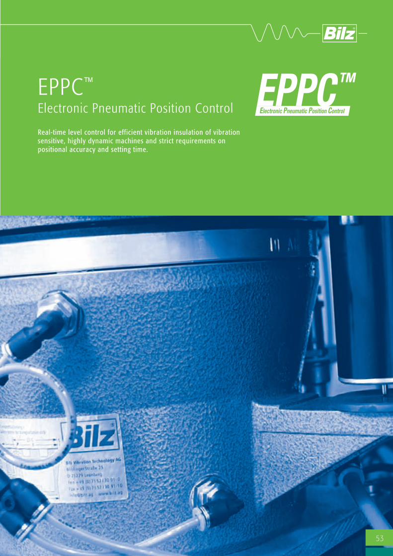
53
Real-time level control for efficient vibration insulation of vibrationsensitive, highly dynamic machines and strict requirements onpositional accuracy and setting time.
EPPC™
Electronic Pneumatic Position Control

54
ELECTRONIC PNEUMATIC POSITION CONTROL EPPCTM
Applications:
n High-precision machines
n Vibration-sensitive and highly dynamicmeasuring machines
n Microscopes
n Test and production machines in thesemiconductor industry
EPPC™ real-time level control achieves anoptimum production accuracy of +/- 8 µmand a significant reduction of the deflectionand settling times in response to dynamicload changes
EPPC™ can be combined with three to six airspring control groups and control up to sixdegrees of freedom. Bilz offer a wide rangeof different size air springs for system design.
The high-performance electronics (14 bit ADconverter, 16-bit signal processor) and
EPPC™ System properties
n Real-time control of up to six degrees offreedom
n Optimum positional accuracy (+/-8 µm)
n Individually adjustable system parameters (such as damping)
n Short deflection and settling times inresponse to load changes
n One high-performance servo valve and onedisplacement sensor per degree of freedom
n Optimized connecting system using CAN bustechnology
n Intelligent browser-based user interface forsetting, diagnostics and monitoring, connec-tion via Ethernet, remote maintenancepossible
n Operator state display, (for example, ready,working position, motion complete, error)
n Digital I/O interface for external control andmonitoring
n Optimized pneumatic design
n Noiseless control using high-resolution signalprocessing and servo valve technology
n Robust and proven air spring technology, canbe combined with Bilz standard air springs
n No disturbing heat generation, magnetic fieldfluctuations or high power consumption as isthe case with electro-magnetic actuators
compressed air valves are mounted directlyto the respective air springs, enabling virtuallynoise-free control without losses due to apressure drop in the hose connections. Theuse of CAN Bus technology ensures thesimplest electrical cabling and makes itpossible to install the control unit up to 20 maway.
In comparison to conventional mechanical-pneumatic level control systems (for exampleBilz MPN) the settling time can be signifi-cantly reduced using EPPC™.
Please watch our EPPC™ video!
Theoretical MPN vibration curve compared with EPPC™. At a deflection of -80 µm the MPN reaches a stableposition within a tolerance of +/-15 µm after 0.75 seconds. With EPPC™ the deflection time is reduced by 45 % to0.4 seconds.
Time [s]
Deflection (m
m)

55
Active IsolationSystem AIS™
n Active electronic-pneumatic vibrationinsulation with up to 6 controlleddegrees of freedom.
n Air springs work as passive air springsand as actuators
n Highly efficient vibration insulationwithout resonance peaks
n Optimum positional accuracy in thevertical direction and horizontal plane
n Minimum deflection and settling time inresponse to machine load changes
n Very powerful real-time controln PLC, CAN bus and one controller andone highly dynamic proportional valveper degree of freedom
n Each controller has a microprocessorand integrated high resolution sensorsfor position, pressure, and acceleration
n User-friendly, intelligentWinSNI/WebVisu-Software for commis-sioning and diagnostics
n Simple digital switching capabilitybetween scanning mode (during sensi-tive machine operations) and loadingmode (in response to machine loadchanges)
n No feed forward signal requiredn No disturbing heat generation, magneticfield fluctuations or high powerconsumption as is the case with electro-magnetic actuators
Active electronic-pneumatic vibration insulation system withpowerful real-time control for the highest demands on effectiveinsulation, deflection and constant level.

56
TRANSMISSION FUNCTION AISTM
VIBRATION CRITERIA VC
Optimum vibration insulation system for highly dynamicmeasuring and testing machines, laser high-resolution micro-scopes as well as inspection and production machines in thesemiconductor industry.AIS™ is used when the insulation effect and reaction times ofconventional passive air spring insulators and a customarylevel control system are not sufficient.
APPLICATION AREA
n Protection of vibration-sensitive machinery from floorvibrations.
n Minimization of structure borne vibration within a system.These are caused by load changes or movements of themachine.
n Settling time reduction.AIS™ enables the highly efficient, vibration insulatedinstallation of highly dynamic machines without loss ofperformance or cycle time.
TASKS
Membrane air spring BiAir®/-ED/HE-MAX
COMPASS PRO Wafer Inspection Machine Electron microscope on a vibrationinsulating platform
AIS™ on Bilz measuring and test bed
Frequency [Hz]
Transm
ission (db)

RS232
Ethernet
CAN-Bus
E/A
Valve
Controller
SPC-LC
Pneumatic hose
PLC
Software WinSNI/WebVisu
BiAir®
air spring
HAB®
air spring
Active Isolation System AISTM
The Bilz AIS™ system is comprised of a PLC, CAN bus, 16-bit statecontroller, highly dynamic proportional valves, the BiAir®
membrane air spring and the HAB™ horizontal air spring. A widerange of different sizes of valves and air springs for system designare availableOne controller and one valve are assigned to one air spring orone group of air springs. AIS™ works with at least threecontrolled groups of air springs and can be used with up to 6degrees of freedom. The controllers are linked with the PLC viaCAN bus. A PC can be linked via a series RS-232 or Ethernet interface forcommissioning and diagnostic purposes. The controller ismechanically coupled with the air spring insulator or to themachine in the direction of the force. Integrated on eachcontroller is a microprocessor, a displacement measuring systemfor position feedback (resolution 0.2 µm), as well as anaccelerometer (resolution 8 µg) and a pressure sensor (resolu-tion 0.2 mbar). The signal sensor sampling rate is 4 kHz. As notonly the higher-level control, but also each controller is equippedwith a microprocessor and highly dynamic proportional valves are
used, we can consider the system to be a powerful real-timecontrol and an elaborate feed forward control from the machinemanufacturer can be omitted.
The PLC also provides digital inputs and outputs, such as ready,pressure monitoring, position and tension, switching betweenscanning/loading mode, emergency stop. The user friendlyswitching capability between scanning and loading mode offers theadvantage of parameterizing the insulation system for machine loadchanges so that it achieves the greatest rigidity, fastest responseand accurate positioning and during machine operations so that itresponds very gently and not aggressively.
SYSTEM DESIGN
57

58
CONTROLLER SPC-LC
Position sensor(resolution 0.2 µm)
RS232 Diagnosticsand updates
Accelerometer (resolution 8 µg)
Microprocessor
CAN Bus (1 MBaud)
Pressure sensor (resolution 0.2 mbar)
Proportional valveMPYE
Dimensions: W / H / D / 483 x 177 x 384 mmDimensions: W / H / D / 483 x 133 x 270 mm
Airsupply
LED status indicatorEthernet interface(Web visualisationlink).
Power supplyswitch
AirBoxinterface
Switch formanual control of the
system
CAN bus interface
Digital I/O interface
Acknowledge error
RS232 interface(WinSNI link)
RS 232 interface(control via external machine control)
Airbearing
Deflate Valvehorizontal
Valvevertical
CONTROLLER 19” PLC AND AIR SUPPLY 19” AirBox
ARRANGEMENT OF THE AISTM SYSTEM FOR AIR SPRINGS AND CONTROLLERS WITH 6 DEGREES OF FREEDOM
Controller 3vertical
Controller 6horizontal
Controller 4horizontal
Controller 5horizontal
Vertical airspringBiAir®
1-ED/HEVertical airspringBiAir®
1-ED/HE
Verticalair springBiAir®
1-ED/HE
Horizontal air spring HABTM 1000
Horizontal air spring HABTM 1000
Horizontal air spring HABTM 1000
Controller 1vertical
Controller 2vertical
1
2
3
4
5
6
45°45°
90°
Application example:Electron microscope on a vibra-tion insulating platform
Right to make technical changes is reserved.
PLC mode switchwith LED indicator
3 position selector switch inflation/deflation/I-O-Mode

59
HABTM
Horizontal air springsHorizontal vibration insulation with AIS TM systems with 6 degrees of freedom.

60
Pneumatic horizontal vibration insulator each comprising of acylindrical upper housing section and lower housing section. The two cylindrical side walls form an annular gap into which theair tubes are inserted and which act against the radially directedrelative movements between the upper and lower sections. Thenecessary horizontal force depending on the machine type or thenatural frequency of the air hoses can be adjusted using thevariable air pressure. A special air bearing is used to carry the vertical load resting onthe upper section and to prevent frictional forces in the horizontalplane
The advantages compared to conventional air springsystems
n Application specific adjustable natural frequency
n Damping in the horizontal plane
n No uncontrolled frictional effects (such as slip-stick effects)
n In combination with AIS™:n No resonance peaksn Above average dampingn Minimum settling timen High positional accuracy
Product description
HABTM HORIZONTAL AIR SPRING
Larger sizes available on request!
Type Item no. Ø A Ø B H Levelling max. vertical max. horizontal Adjustable bolt load capacity force absorption horizontal at 5.5 bar at 1 bar natural frequency mm mm mm N N HzHABTM 280 53-0055 200 180 101 M10 x 1.5 3400 150 1.1 – 1.9HABTM 660 53-0084 250 230 118 M10 x 1.5 7200 380 1.1 – 1.9HABTM 1000 53-0023 300 276 159 M12 x 1.5 11000 490 1.1 – 1.9HABTM 1000-HL 53-0025 300 276 159 M12 x 1.5 14000 490 1.1 – 1.9HABTM 24000 53-0039 350 326 172 M16 x 1.5 23500 700 1.1 – 1.9HABTM 38000 53-0069 422 398 187 M16 x 1.5 38000 1100 1.1 – 1.9
Levelling screwAir bearing
Air hose
Transport /centring screw
Right to make technical changes is reserved.
Patents: German patent no. 102 49 647.1 – German patent no. 102 49 647
Noten In addition to our standard solutions listed here we also supply
numerous special solutions. Please contact us, we would be happy to advise you.
(2x) Air hose Air bearing
Granite Air gap approx. 3 µm

61
Active vibration insulation in 6 degrees of freedom offering the best possible insulation effect
Active Isolation System AISTM
High Performance
FUNCTION ADVANTAGES
With an elastic machine mount on vertical air springs (suchas Bilz BiAir ®-ED) the insulated mass is carried on a volumeof air enclosed by a membrane in the interior of theinsulator. Because of the elastic properties of this air springmembrane the insulator has free movement in the verticalplane, and also a limited movement in the horizontal plane.
For extremely sensitive and high-precision applications, whichmust be mounted with 6 degrees of freedom, these slighthorizontal elastic properties can have undesired influence onthe work results.
In this case the HAB horizontal air spring is used purely as anair bearing to reduce frictional effects; the required horizontalcounter forces are generated by additional BiAir®elements.These additional BiAir® elements are fitted rotated 90° andreplace the air hoses of the regular HAB™ air springs (see theHorizontal air springs section ).
n Best possible insulation properties specifically for applica-tions with critical limit curves in the low frequency range.
n For applications with higher horizontal dynamics signifi-cantly higher counter forces can be realized by theadditional BiAir® air springs than with standard AIS with 6degrees of freedom.

Noise and vibration insulation ofresearch laboratories
The illustration showssome of the most impor-tant measures forreducing externaldisturbing influences inthe “noise-free labs” ofBinnig and RohrerNanotechnology Centersof IBM and ETH inZurich.
62

63
The manufacture and characterising of ever smaller components,down to structures comprising of only a few molecules or atoms,make the highest demands on vibration insulation to protect thevibration-sensitive systems.
In order to precisely perform sensitive experiments and measure-ments in the nanometre range (1 nanometre = one millionth of amillimetre), the external disturbing influences such as tempera-ture, humidity and air pressure fluctuations, noise, electromag-netic fields or floor vibrations must be kept to an absoluteminimum level.
Globally respected as a competent partner, Bilz have specializedin solutions such as laboratory insulation (foundation block orplatform insulators) or the direct insulation of highly sensitivemachines (installation of insulation systems in machinery/plant.)
Passive membrane air springs, air springs or active vibrationinsulator systems are used for high-quality vibration insulation.
Depending on the customer’s wishes Bilz also creates thecomplete foundation block or platform design, or providessupport in the design and constructive integration of the insula-tion in the machine.
We are very proud to have equipped the most modern researchlaboratories in the world with noise and vibration insulation,these include the “Precision laboratories MPI Stuttgart” or the“Noise-free lab” of the Binnig and Rohrer Nanotechnology Centre(IBM /ETH Zurich).
In the field of semiconductors renowned companies such asApplied Materials, Visotec and Zeiss are among our most esteemedcustomers.
Experimentation room with 4.2 m clear room height and acoustic insulation materials (supplied and installed by Bilz). Source: Binnig and Rohrer Nanotechnology Center (IBM Research, Zurich).
Result of vibration measurements on a foundation block insulated with Bilzmembrane air springs.
Active vibration insulation AIS™ High Performance by Bilz, which suspends the glassfibre reinforced plastic armoured foundation block weighing 75 tons on air cushions.

64
Room acoustics and technical noise protectionBilz acoustic elements enable optimized room acoustics and airborne noise insulationin office and industrial buildings, laboratories and test cells.
Our high-quality solutions for absorbing noise energy are distinguished by maximumnoise insulation and minimisation of the associated sound pressure levels and theresulting resonance period.

NOTE:
Bilz acoustic elements are availablein various versions to matchindividual requirements such as wallelements, ceiling sails, enclosures,etc. Our delivery range also includesimpact resistant, non-flammable(material class A2 according toDIN 4102) to suit the particular appli-cation.
The material can also be colour dyedor covered with printable fabric onrequest.
65
When a sound wave strikes a body it is partially absorbed andpartially reflected depending on the hardness and porosity of thematerial. The ratio between the occurring and absorbed soundenergy is therefore the sound absorption coefficient, whichusually lies between 0 (complete reflection) and 1 (completeabsorption).
The sound absorption EA therefore indicates the process ofreducing sound energy Eo in particular (but not necessarily) byconversion into heat.
The distinction from dissipation ED is that this exclusively refers tothe conversion into energy other than sound, in particular heat.
Variable and cost-effective acoustic solutions usingBilz surface elements. Very easily retrofitted.
For further information about our products and installation services please call to arrange a personal consultation.
Source: Binnig and Rohrer NanotechnologyCenter (IBM Research, Zurich).
Bilz absorber foam element. Excellent insulation proper-ties due to its distinctive profiling
Surface S
Absorption
Sound energy
Reflection
Dissipation
Transmission
E0
EA
ED
E1
ER

66
Effective and reliable shielding from low frequency magnetic fields for highly sensitivedevices and applications such as electron microscopes, nanotechnology and biomag-netic examinations.
Disturbing influences are extensively neutralised with opposing fields with reversedpolarity. Cable loops are laid around the work area to be protected and opposing fieldsare generated in real time using magnetic field compensation devices that continuouslymeasure the actual electromagnetic value. This method is an effective and cost-efficient alternative to expensive magnetic fieldshielding, for example with metal.
Magnetic field compensation

67
Besides natural magnetic fields that exist everywhere in theuniverse, the majority of problems encountered when operatingsensitive devices arise from low-frequency magnetic fields thatare caused by human activities, such as those emanating fromelectrical power cables, railways vehicles, elevators, etc. Thesefields occur as soon as electricity flows through a conductor.Without suitable shielding, they expand outwards in a circularform and are quite capable of passing through most materialsunhindered. Magnetic field compensation has established itself as the mostcost-effective solution. With this method the magnetic field iscontinuously measured and a compensation device, whichincludes the necessary control electronics and power amplifier forthe direct connection of compensation coils, generates anopposing field. The compensation coils can be made of coiledcables that are laid at the edges of the laboratory, or as acomplete solution integrated in a self-supporting aluminiumframe.
Applications
n Image enhancement in electron microscopy (REM and TEM)
n Biomagnetic applications
n Compensation of mains frequencies (50/60 Hz) and harmonicwaves
n Suppression of slow and stepped magnetic fields caused byvehicles, moving magnetic objects, elevators, etc.
n A special version for MRI applications is available
REM image without (above) and with (below) magnetic fieldcompensation
Integrated coil frame from Bilz for magnetic field compensation
n 3 axis automatic real-time compensation of low frequency magneticfield disturbance
n Frequency range DC to 1.000 Hz (1kHz)
n Fluxgate magnetic field sensor with sub Nano Tesla resolution
n Controller mode: AC, DC, AD+DC
n 40 db typical suppression of 50 Hz disturbance
n Compensation coil connection capability
n Measured value and alarm display
For further information about our products and installation services please call to arrange a personal consultation.
Bilz magnetic fieldcompensation system
Bilz magnetic field compensation using room coils

68
Vibration insulated tablesIndividually tailored to your requirements.

69
Applications
n Vibration-sensitive measuring and testing equipment
n Laser equipment
n Optical and electronic instruments
n Scales
n Medical instruments
Technology
The Bilz laboratory table LTH is a vibration insulated work placeand can be used for all applications where vibrations and/orchanges in level cause sustained disturbances to the experiment orwork.Disturbing vibrations from the environment are isolated by meansof highly effective membrane air spring insulators and the solidhard stone plate.At the same time the mechanical-pneumatic level control automati-cally ensures that the level is retained to an accuracy of up to±1/100 mm even with load changes.The maintenance unit for compressed-air conditioning is included.
LTH laboratory tableParticularly robust and resistant
Product properties
n Adjustable table feet
n Ridged, welded steel subframe
n BiAir® membrane air spring (vertical natural frequency approximately 3 Hz) between the subframe and table top
n Magnetic-pneumatic level control (level accuracy ± 1/100 mm or ± 1/10 mm, depending on the valve used)
n Table top made from hard stone with a ground finish
n Painting as desired by the customer
n Standard colour: RAL 9005
Dimensions LTH 60-50 LTH 80-60 LTH 100-63 LTH 90-75 LTH 100-80 LTH 100-100 LTH 120-80 LTH 150-100 LTH 200-100Width [mm] 600 800 1.000 900 1.000 1.000 1.200 1.500 2.000Depth [mm] 500 600 630 750 800 1.000 800 1.000 1.000Thickness (hard stone) [mm]100 120 100 100 140 160 160 190 220Working height [mm] 760 760 760 760 760 760 760 760 760max. Load [N] 2.500 2.500 3.000 3.600 7.000 7.000 7.000 18.000 28.000
LTH LABORATORY TABLE STANDARD SIZES.
Further dimensions are available on request
Right to make technical changes is reserved.

70
Applications
n Construction of laser optical systems and interferometers
n Special microscopes
Technology
Work places from Bilz are distinguished by their excellent qualityand functionality. Optical work places should offer optimumrigidity and damping with low density. Bilz LTO honeycomb tops are optimised in regard to theirdamping response so that the usual high resonance amplitude inthe higher frequency range are attenuated by the tables in the HDseries by their natural damping.
LTO optical table Excellent quality and functionality
Product properties
n As LTH (see page 69)
n Optical table tops:– HD steel honeycomb core with high natural damping, cover plate without thread insert– HDT as HD, but with thread inserts
n Variants: Standard, clean room (base plate in stainless steel)
n Also available with BiAir® OC or BiAir® PAS as an option (see p. 72/73)
Dimensions LTO 60-50 LTO 90-60 LTO 120-60 LTO 150-90 LTO 200-100 LTO 240-120 LTO 300-150Width [mm] 600 900 1.200 1.500 2.000 2.400 3.000Depth [mm] 500 600 600 900 1.000 1.200 1.500Thickness [mm] 100 100 100 150 200 200 300Working height [mm] 760 760 760 760 760 760 760max. load [N] 1.500 2.000 3.000 5.000 5.000 7.500 7.500
LTO OPTICAL TABLE STANDARD SIZES
Description of the table tops:
Cover plate: Stainless steel 3 mm, magnetic or non-magnetic, anti-reflective.
Base plate: Steel sheet 3 mm
Clamping hole grid: 25 mm (standard)
Core: HD/HDT: Steel honeycomb made ofgalvanised 0.5 mm steel sheet, preci-sion formed, bonded with specificallymatched resin
Thread inserts (HDT): Floating mounted threaded inserts M6,closed sleeves prevent any contact withthe table core. Capability to displacethe clamping screws by 0.5 mm whilstsimultaneously inclining by ±3°.Maximum depth of thread 30 mm.
Further dimensions are available on request.
Right to make technical changes is reserved.

71
Compile the equipment features for the optimum laboratory table for your application:
Individual design
n Additional holes/threads in the table top and the subframe
n Special sizes on request
n Can be equipped with metal guide rails on request
Subframe
Levelling elements and rollers are available in various different designs and sizes.
BiAir® FAEBI®
Options
Different frames in standard or special sizes
Cover hood
Holders for
Profiles and bracketsfor additional components
Powder coating in RAL colors
Levelling elements
Set of rolls
Wooden plate:
• Differents sizes
• Cutout
• Rounded corners
Differents materials (wood,metal) and colors for:• Doors• Base plates/inserted plates• Housing
monitor, keyboard,mouse
Arm rest
Insulatorsn Level control (mechanical or electronic)n Accessories (e.g. compressed-air control)n Insulators perfectly integrated in the subframe

7272
Applications
n Vibration-sensitivemeasuring and testingequipment e.g. atomic forcemicroscopes (AFM), inter-ferometer
Technology
Due to their increased air volume the newly-developed BiAir® OCair springs achieve a reduced natural frequency of approximately2 Hz in the vertical plane. The laboratory tables with BiAir®OC airsprings are suitable for applications with lower dynamics thatrequire an excellent insulation effect.
LTH-Laboratory tables with BiAir® OCProduct properties
n As LTH (see page 69)
n Table top from hard stone with ground finish
n Design with membrane air spring insulators BiAir® OC between table top and subframe
n Also available with optical tops as an option (see page 70)
Dimensions LTH 60-50-OC LTH 80-60-OC LTH 100-63-OC LTH 90-75-OC LTH 100-80-OC LTH 100-100-OC LTH 120-80-OCWidth (mm) 600 800 1.000 900 1.000 1.000 1.200Depth (mm) 500 600 630 750 800 1.000 800Thickness Hard stone (mm) 100 120 100 100 140 160 160Working height (mm) 760 760 760 760 760 760 760max. load [N] 2.500 2.500 3.200 3.200 7.000 7.000 7.000
LTH LABORATORY TABLES WITH BIAIR® OC STANDARD SIZES
OC = one chamber
Right to make technical changes is reserved.

73
Applications
n Vibration-sensitive measuring and testing equipmente.g. atomic force microscopes (AFM), interferometers
Technology
Newly developed pendulum suspended BiAir® PAS air springsachieve a reduced vertical natural frequency due to theirincreased air volume and also have reduced natural frequency inthe horizontal plane due to their pendulum suspension arrange-ment. This enables the laboratory table with pendulum air springs toreach a natural frequency of approximately 2 Hz in the verticalplane and approximately 1.2 Hz in the horizontal plane. Thelaboratory table with pendulum air springs is suitable for applica-tions with low dynamics and higher requirements for vibrationinsulation in both the vertical and horizontal planes.
LTH-Laboratory tables with BiAir® PASProduct properties
n As LTH (see page 69)
n Table top from hard stone with ground finish
n Design with pendulum suspended membrane air spring insulators BiAir® between table top and subframe
n Also available with optical tops as an option (see page 70)
Dimensions LTH 60-50-PAS LTH 80-60-PAS LTH 100-63-PAS LTH 90-75-PAS LTH 100-80-PAS LTH 100-100-PAS LTH 120-80-PASWidth (mm) 600 800 1.000 900 1.000 1.000 1.200Depth (mm) 500 600 630 750 800 1.000 800Thickness Hard stone (mm) 100 120 100 100 140 160 160Working height (mm) 760 760 760 760 760 760 760max. Load [N] 2.500 2.500 3.200 3.200 7.000 7.000 7.000
LTH LABORATORY TABLES WITH BIAIR® PAS STANDARD SIZES
Subframe of a laboratory table with BiAir® PASand LCV level control
PAS = pendulum air spring

74
BILZ-VITAP® Vibration insulating table platformProduct properties
n Portable, robust, powder coated metal housing with integratedBilz rubber air springs FAEBI® or optionally with Bilzmembrane air springs BiAir®; colour: RAL 7037, dusty grey
n Equipped with very simple through to very convenient Bilzlevel control systems
n A ground-finished hard stone plate lies on the insulators as asupport base and solid base mass
n Available with and without a connection to an externalcompressed air supply
Applications
n For very light and very small measuring or test equipment
n Weight range up to 200 kg
n Optical devices, optical microscopes, microscopes with a CCDcamera, inspection microscopes, small surface roughness androundness measuring equipment, hardness testers, analyticalbalances, applications in industrial production environments,laboratories and measuring rooms up to clean rooms. Alsosuitable for the portable use of these measuring devices.
VITAP®-F VITAP®-FP VITAP®-BM
With long-term tried and testedBilz FAEBI® rubber air springswith non-return valve.Integrated hand pump,no compressed air supplynecessary.
With long-term tried andtested Bilz FAEBI® rubber airprecision pressure control forconvenient height adjustment. Connection to an externalcompressed air supply.
With highly efficient Bilz BiAir®
membrane air springs and withmechanical-pneumatic levelcontrol (MPN) with automaticlevel compensation in responseto load changes. Connection toan external compressed airsupply.
Item no.. Dimensions mm Dimensions mm Height Load capacity Natural frequency Compressed air Platform box Installation surface mm N Hz supplyVITAP®-F 50-40 56-0008 540 x 440 500 x 400 95 600 4.5 – 6 autonomous/air pumpVITAP®-F 60-50 56-0009 640 x 540 600 x 500 95 1.300 4.5 – 6 autonomous/air pumpVITAP®-FP 50-40 56-0010 540 x 440 500 x 400 95 600 4.5 – 6 4 bar/air pressure networkVITAP®-FP 60-50 56-0011 640 x 540 600 x 500 95 1.300 4.5 – 6 4 bar/air pressure networkVITAP®-BM 50-40a 56-0006 540 x 440 500 x 400 95 750 1.8 – 3 6 bar/air pressure networkVITAP®-BM 50-40b 56-0005 540 x 440 500 x 400 95 1.500 1.8 – 3 6 bar/air pressure networkVITAP®-BM 60-50a 56-0002 640 x 540 600 x 500 95 1.500 1.8 – 3 6 bar/air pressure networkVITAP®-BM 60-50b 56-0003 640 x 540 600 x 500 95 2.000 1.8 – 3 6 bar/air pressure network
TECHNICAL DATA VITAP®-F, VITAP®-FP, VITAP®-BM
Right to make technical changes is reserved.

75
Indirect insulationElastic mounting of machines with insufficient intrinsic rigidity.
Enhanced insulating effect and reduced vibration amplitudes throughadditional mass and lowering of the centre of gravity.
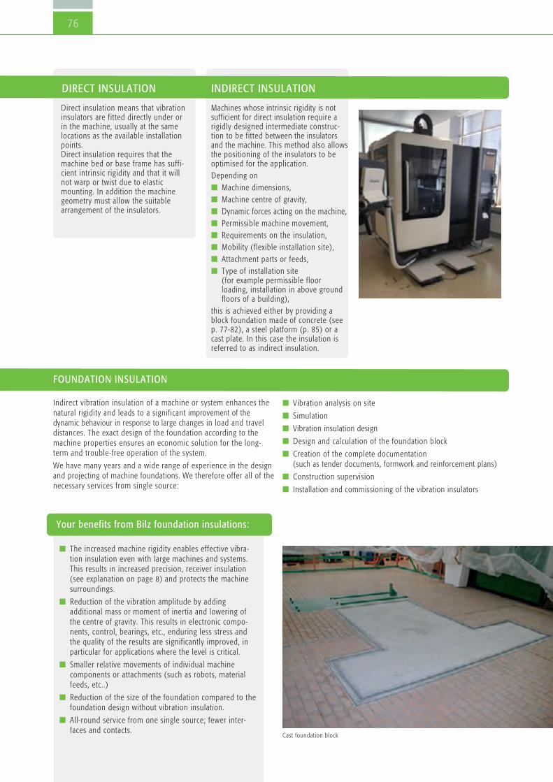
76
FOUNDATION INSULATION
Your benefits from Bilz foundation insulations:
Indirect vibration insulation of a machine or system enhances thenatural rigidity and leads to a significant improvement of thedynamic behaviour in response to large changes in load and traveldistances. The exact design of the foundation according to themachine properties ensures an economic solution for the long-term and trouble-free operation of the system.
We have many years and a wide range of experience in the designand projecting of machine foundations. We therefore offer all of thenecessary services from single source:
n The increased machine rigidity enables effective vibra-tion insulation even with large machines and systems.This results in increased precision, receiver insulation(see explanation on page 8) and protects the machinesurroundings.
n Reduction of the vibration amplitude by addingadditional mass or moment of inertia and lowering ofthe centre of gravity. This results in electronic compo-nents, control, bearings, etc., enduring less stress andthe quality of the results are significantly improved, inparticular for applications where the level is critical.
n Smaller relative movements of individual machinecomponents or attachments (such as robots, materialfeeds, etc..)
n Reduction of the size of the foundation compared to thefoundation design without vibration insulation.
n All-round service from one single source; fewer inter-faces and contacts.
Direct insulation means that vibrationinsulators are fitted directly under orin the machine, usually at the samelocations as the available installationpoints. Direct insulation requires that themachine bed or base frame has suffi-cient intrinsic rigidity and that it willnot warp or twist due to elasticmounting. In addition the machinegeometry must allow the suitablearrangement of the insulators.
Machines whose intrinsic rigidity is notsufficient for direct insulation require arigidly designed intermediate construc-tion to be fitted between the insulatorsand the machine. This method also allowsthe positioning of the insulators to beoptimised for the application.Depending onn Machine dimensions, n Machine centre of gravity, n Dynamic forces acting on the machine,n Permissible machine movement,n Requirements on the insulation,n Mobility (flexible installation site),n Attachment parts or feeds,n Type of installation site
(for example permissible floorloading, installation in above groundfloors of a building),
this is achieved either by providing ablock foundation made of concrete (seep. 77-82), a steel platform (p. 85) or acast plate. In this case the insulation isreferred to as indirect insulation.
n Vibration analysis on site
n Simulation
n Vibration insulation design
n Design and calculation of the foundation block
n Creation of the complete documentation(such as tender documents, formwork and reinforcement plans)
n Construction supervision
n Installation and commissioning of the vibration insulators
Cast foundation block
DIRECT INSULATION INDIRECT INSULATION

77
1 Foundation pit (side wall)2 Mineral fibre and cover plate (lost framework) 3 Foundation block 4 PVC foil cover 5 Bilz insulation pads (set of pads)6 Foundation pit (base)
Insulation pads are perfectly suitablefor the vibration insulation of foundations
1
2
4 2
5
6
3
Vibration foundationwith insulation pad setsApplication example:Foundation insulation with insulation pads and lost formwork
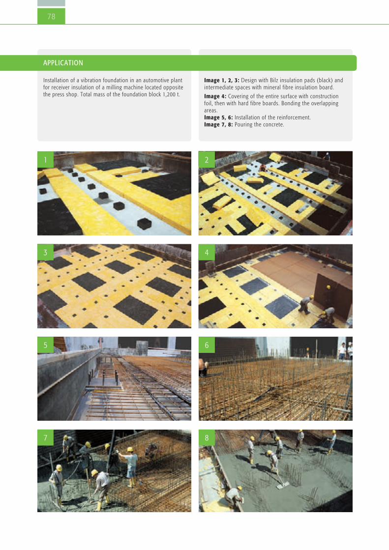
78
APPLICATION
Installation of a vibration foundation in an automotive plantfor receiver insulation of a milling machine located oppositethe press shop. Total mass of the foundation block 1,200 t.
Image 1, 2, 3: Design with Bilz insulation pads (black) andintermediate spaces with mineral fibre insulation board.
Image 4: Covering of the entire surface with constructionfoil, then with hard fibre boards. Bonding the overlappingareas. Image 5, 6: Installation of the reinforcement. Image 7, 8: Pouring the concrete.
1 2
3 4
5 6
7 8

79
Vibration foundationwith FAEBI®
Bilz scope of supply and services
8 x Bilz FAEBI® 580 HD with mechanical-pneumatic level controlMPN-LCV
Planning services
n Creation of the foundation
n Static calculations
n Formwork and reinforcement plans
n Steel and steel bending schedule
Requirements
n A maximum of 3 weeks loss of production.
n Special shape 5 corner
n Tight space conditions and entry to the inspection channelthrough the foundation block
n Extremely small permissible horizontal movements of themachine
n Reliable source insulation for suppressing the disturbing vibra-tions in the adjacent building, 2. floor, from 10 Hz.
Application example:
Foundation insulation with FAEBI® rubber air springs and level control.Implementation with pre-cast concrete slabs.

80
APPLICATION
Punching machine, machine weight including the tool andaccessories approximately 23 t, dynamic forces verticalapprox. 60 kN, horizontal approx. 30 kN, foundation blockapprox. 5.1 x 3.5 x 1.0 m, weight approx. 40 t.

81
The foundation insulation using low-frequency BiAir® membraneair springs enables an optimum insulation effect. Unlike with the use of pad sets or steel springs the adjustablelevel of the foundation block automatically resets itself inresponse to load changes through the level control.
Bilz scope of supply and services
8 x Bilz membrane air springs BiAir® 4-ED with mechanical-pneumatic level control MPN-LCV.
Particular general conditions
The processing accuracy required of the roller grinding machinecannot be met due to disturbing influences from adjacentmachines and an overhead crane rail. Large travel distances andtools weighing up to 10t cause large load changes that necessitatethe use of a fast, mechanical-pneumatic level control with a levelaccuracy of ± 0.1 mm.
Vibration foundationwith BiAir®
Application example:
Foundation insulation with BiAir® membrane air springs and level control. Implementation with pre-cast concrete slab.

82
APPLICATION
Gear grinding machine GLEASON PFAUTER P 1200 G, machine weight incl. tool up to 25 t, foundation block approx. 5.2 x 1.9 x 0.7 m, approx. 20 t

83
Static and dynamic calculations / reinforcementplans / FEM analysis
Foundationblock naturalmodes FEM image (example), shown greatly exaggerated

84
Foundation insulation with insulation padsDesign plan (example)
Block bending under the influence of alternating loads FEM image (example)

n Frequency analysis and vibration measurement
n Simulations
n Design, manufacture, delivery, assembly and commissioning of total vibration insulation systems
n Manufacture, supply and installation of cast platforms
n Manufacture, delivery and installation of cast plates
85
Vibration insulation platforms
Basic platform Platform for minimum installation heightand for systems with a very high centre ofgravity
Platform for low installation height and forsystems with a high centre of gravity
Many applications require indirect insulation due to the require-ments for effective insulation and level control or due to insuffi-cient intrinsic rigidity. If foundation insulation is not possible ase.g.
n installation is on the elevated floors of a building,
n the site of installation is of restricted space,
n the site of installation should be flexible (mobility),
then mounting the machine to a vibration insulated platform is aproven solution.
Usually either welded steel constructions or cast plates are used.Depending on the design of the platform the base of the machineis additionally extended and the centre of gravity is lowered byadding mass or the position of the insulators, which significantlyenhances the stability of the overall system. In this way machineswith a high centre of gravity and/or small base area can also bemounted to very low frequency and therefore soft insulators.
DESIGN EXAMPLES
SERVICES
Platform for integration in double/clean room floors withadditional mass for the reduction of vibration peaks

Low-frequency vibration insulation for demanding and highlydynamic applications
86
Test beds

87
Vibration insulation of test beds Parallel to the ever increasing demands on test beds and testsystems for the automotive industry over recent years, thesystems for vibration insulation have also been developing at thesame pace.
Vibration foundations for special test beds
n Engine test beds
n Articulated test beds
n Formula-1-test beds (BMW,
Mercedes, Ferrari, Toyota, Renault)
n Gearbox test beds
n Acoustic test beds
n Rolling road test beds
n Shaker
n Sliding table
n Cylinder test beds
n Special test beds
n Hydropulser
n Road simulation test beds
n Frequency analysis and vibrationmeasurement
n Simulations
n Design, manufacture, delivery,assembly and commissioning ofvibration insulation systems
n Design, supply and installation ofcast iron plates
n Production of static and reinforce-ment plans for foundation pits and–blocks
n Preparation of tender documents,price comparison, cost estimation
n Construction supervision
APPLICATION EXAMPLES
SERVICES
Convenient and powerful air spring systems with level controlhave proven themselves ideal for very advantageous solutionconcepts. For the vibration insulation of test beds and aggregateswith particularly high dynamic forces an additional seismic massin the form of a concrete foundation is also needed, see p.76.
Vibration insulation caststeel platform
Vibration insulation concrete block or steel platform
For further information contact us to arrange a personal consultation.

88
Measurement and vibration analysisMeasurement of vibrations and shocks using state of the art instruments –FFT Analyser and analysis software
Due to our decades of experience in the fieldof vibration technology and isolation, weguarantee you technically and economicallyreliable problem solutions. The on sitemeasurement and analysis of vibrationemissions and immissions is an essential partof our consulting services with regard tovibration and vibration insulation. Based onthe measurement results, we develop vibra-tion technical measures to comply withlegally prescribed limits.
The assessment of periodic and non-periodicvibrations in the frequency range from 1 Hzto 80 Hz is e.g. based on the DIN 4150“Vibrations in buildings; Effects on persons inbuildings”. Requirements and referencevalues are stated herein, in general theconsiderable disturbance of people indomestic properties and similar premises isto be avoided in order to comply with theseregulations.
Procedure
In the first step the maximum value of thevibration levels for the three directionalcomponents x, y and z are determined.The largest of these three values KBFmaxis compared with the reference values Au andAo according to Table 1
n If KBFmax is less than or equal to the(lower) reference value of Au, then therequirements of this standard are met.
n If KBFmax is more than the (upper) refer-ence value of Au, then the requirements ofthis standard are not met.
n For short-term impacts and those that donot occur often, the requirement of thestandard is met if KBFmax is less than orequal to Ao.
Another current example of the requirementfor a vibration analysis is the storage of high-precision 3D-measurement machines, as wellas other testing, measuring or grindingmachines. Typically measurements must becarried out by such machines at the plannedsite, to ensure that existing ground vibrationsdo not exceed the permitted values (see Chart1). To do this, the vibration acceleration is
determined within a given frequencyspectrum (1–100 Hz), as a simple sum valuemeasurement would provide insufficientinformation about the exact environmentalconditions. The analysis of the accelerationtime signals is carried out using a fast-fourier-analyser, which indicates the correspondingmeasurement value (vibration acceleration ing) for each frequency of the spectrum. If thedisturbances (vibration interference) are outof the permissible range, the appropriateinsulation can be determined with the help ofour PC calculation program.
Very accurate vibration analysis in the lowerfrequency range are carried out with highlysensitive Geophones. Vibration speeds frombelow 0.01 μm/s in the range from 0.2 to30 Hz can be recorded with the Geophones.Extremely precise measurements of vibrationare necessary for an optimal and customer-specific design, particularly in the semicon-ductor and Nanotech industry as well as forhigh-precision 3D-measurement machines.
Assignment

89
daytime nightime
Permissible range
(0.1
KB ac
cord
ing to
VDI 2
057)
(0.2
KB ac
cord
ing to
VDI 2
057)
Line Impact site Au Ao Ar Au Ao Ar1 Impact sites, in whose vicinity only commercial facilities and where appropriate are housed 0.4 6 0.2 0.3 0.6 0.15 with the exception of where the owner and manager of operations, as well as supervisory and stand-by persons are housed (see Industrial estates § 9 BauNVO))2 Impact sites, in whose vicinity mainly commercial 0.3 6 0.15 0.2 0.4 0.1 facilities are housed (see Industrial estates § 8 BauNVO) 3 Impact sites, where neither predominantly commercial facilities 0.2 5 0.1 0.1 0.2 0.15 nor predominantly domestic property are housed (see Core areas § 7 BauNVO, mixed areas § 6 BauNVO, village areas § 5 BauNVO) 4 Impact sites, in whose vicinity predominantly or exclusively domestic property 0.15 3 0.07 0.1 0.2 0.3 is housed (see Pure residential areas § 3 BauNVO, General residential areas § 4 BauNVO, Small housing estates § 2 BauNVO)5 Particularly vulnerable impact sites, for example in hospitals, sanatoriums, 0.1 3 0.05 0.1 0.15 0.07 in so far as the are situated in those areas specially designated for them.
In brackets the areas of the Federal Land Utilisation Ordinance = BauNVO are specified, usually represented by the designations under line 1 to 4.A schematic equation is not possible because the designations under line 1 to 4 are only made after the grounds have been established to protect against exposure to vibration, the zoning ofthe area in the BauNVO takes into account however also other planning requirements.
in domestic property and similar premises
REFERENCE VALUES A FOR THE ASSESSMENT OF VIBRATION EMISSIONS
Table 1: Limit values DIN 4150
Chart 1: Example CMM limit curve Chart 2: Vibration Criteria VC
FFT Analyser Geophone
Vibration acceleration in g
Acceleration values in this range require vibration insulation
Vibration acceleration in m/s -2 Frequency (Hz)

90
Company headquartersand sales partners
90

On the same wavelengthas our customers.
Bilz Vibration Technology AG is acompany that was founded in1985, which mainly deals with theinsulation of vibration and structure-borne noise of machin-ery and equipment. We havetaken a leading position in Europein this very specialized field as asupplier of mechanical and plantengineering to e.g. both the auto -motive and semiconductor indus-try and its suppliers.
Our company history:1985 Founded as BilzSchwingungs technik GmbH
2006 Transformation into a stockcompany and renamed Bilz
Vibration Technology AG
Our product range covers a verywide range of applications. Fromthe insulation of a single presswith insulation pads up to the aircushioning of highly sensitiveequipment in the semiconductorindustry, there is virtually no tech-nical vibration problem for whichwe cannot provide an efficient andcost-effective solution.
We are also always able to respondto different customer requirementsquickly and flexibly due to the highlevel of in-house vertical integra-tion.
2
BELGIUM / LUXEMBOURGSchiltz SA. NV.Chaussee de Gand 1034B-1082 BrusselsTel. + 32 2 4 64 48 45 Fax + 32 2 4 64 48 49 [email protected]
BOSNIA & HERZEGOVINA,KOSOVO, CROATIA, MACEDONIA, MONTENEGRO, SERBIA, SLOVENIAIB Blumenauer KGHauptstrasse 7D-83112 FrasdorfTel. + 49 8052 3 74 Fax + 49 8052 43 55 Mobile + 49 175 1 67 [email protected]
BRAZILHOMMEL-TECH Com. Imp. eExp. Ltda NOVO ENDEREÇO:Avenida Artur de Queirós, 134Bairro Casa BrancaBR-09015-510-Santo André -SP Tel. + 55 11 49 79 53 00 Fax + 55 11 44 36 68 [email protected]
BULGARIANikolay Marinow ET MesstechnikMladost, Bl.45, Vh.12, App.194BG-1784 Sofia Tel. + 359 2 9 74 45 70 Fax + 359 2 8 74 20 [email protected]
CHINABilz (Shanghai) Vibration Technology Co., Ltd.Room 1301, No 525, Chengyin Road Shanghai 200000P.R. ChinaTel. + 86 13 7 74 32 20 [email protected]
DENMARK/ICELANDTP GruppenKorskildelund 4DK-2670 GreveTel. + 45 70 10 09 66Fax + 45 70 10 01 [email protected] www.tp-gruppen.dk
ENGLANDPES (UK) LIMITEDWatling CloseSketchley Meadows Business ParkGB-Hinckley, Leics. LE10 3EZTel. + 44 1455 25 12 51Fax + 44 1455 25 12 52 [email protected]
FINLANDKvalitest Nordic Oy Huutokalliontie 20840800 Vaajakoski, FINLANDTel. + 35 8 4 05 52 98 [email protected]
FRANCE/VIB & TEC – TECHNOLOGIEANTIVIBRATOIRE2 rue de ColmarF-68220 Hésingue Tel. + 33 3 89 69 11 90Fax + 33 3 89 69 04 [email protected]
INDIAMachine House India Pvt. Ltd.W 82 (A) MIDC AMBADNashik, MaharashtraTel. + 91 253 2 38 22 55Fax + 91 253 2 38 60 [email protected]
IRANJ&M Global Trade E.K.Eupener Str. 161-E6050933 CologneGermanyTel. +49 (0) 221 50 60 87 41Fax +49 (0) 221 50 60 87 [email protected]
ISRAEL Baccara Geva Ltd.IL-1891500 Kvutzat GevaTel. + 972 4 653 59 60Fax + 972 4 653 14 [email protected]
ITALYGiquattro Srl.Via Aristotele 24 / 5I-20128 MilanoTel. + 39 2 2 55 31 70 Fax + 39 2 2 57 28 [email protected]
JAPANNabeya Co. Ltd.25 Wakasugicho, GifuZip-Code 500-8743 Tel. + 81 58 273 65 21Fax + 81 58 278 00 22 [email protected]
Metrotec Corporation2-25-35 Ohya-kita,Ebina City, KanagawaPref. 243-0419 Tel. + 81 46 206 00 11Fax + 81 46 206 00 22Mobil: + 81 90 77 23 39 [email protected]
NETHERLANDSOude Reimer BVWillem Barentszweg 216NL-1212 BR HilversumTel. + 31 35 6 46 08 20 Fax + 31 35 6 85 70 [email protected]
POLANDEKKONul. Poziomkowa 1B/13PL-11-041 Olsztyn Mobile + 48 792 88 64 [email protected]
PORTUGAL EQUINOTEC, SA.Av. Villagarcia de Arosa 1120P-4450-300 Matosinhos Tel. + 351 22 9 35 07 55 Fax + 351 22 9 35 10 [email protected]
ROMANIAPATRASCU & GANE ENGINEERING COMPANY S.R.L. Str. Dreptatii nr. 79B, Sector 6, RO-060883 BucurestiTel. + 40 212 22 95 40 Fax + 40 212 22 95 [email protected]
SWEDENSERVITEC NYQVIST ABFjällgatan 49 ASE 504 61 BoråsTel. + 33 22 88 66Fax + 33 22 88 67 Mobile +33 704 41 88 [email protected]
SWITZERLAND VIB & TEC – TECHNOLOGIEANTIVIBRATOIRE15, rue de Saint-LouisF-68220 Hésingue Tel. + 33 3 89 69 11 90Fax + 33 3 89 69 04 [email protected]
SPAINElorbi S.A.Botica Vieja 17Deusto, E-48014 Bilbao Tel. + 34 944 75 34 72 Fax + 34 944 47 38 [email protected]
SOUTH AFRICAFa. Remag (PTY) Ltd.Midrand, Midway ParkP.O. Box 2281ZA-1685 South AfricaTel. + 27 11 315 56 72Fax + 27 11 315 56 [email protected]
SOUTH KOREAYONG BEE TRADING CORPORATIONSaeol bldg., 82-4, Yangjae-dong, Seocho-gu,Seoul 137-130 KoreaTel. + 82 2 5 76 60 22Fax + 82 2 5 76 60 27 [email protected]
SOUTH EAST ASIA(SINGAPORE, THAILAND,MALAYSIA, VIETNAM, IN-DONESIA, PHILIPPINES)Bilz Asia Pacific Pte Ltd.152 Beach RoadGateway East Tower 14-03Singapore 189721Tel. + 65 63 69 61 90Fax + 65 63 69 37 68H/P+ 65 97 30 44 [email protected]
TAIWANJOIN STAR TRADING CO., LTD4th Floor, No. 3, Alley 6, Lane 45, Bao-Xing Rd.Hsin Tien District, New Taipei city 23145, Taiwan R.O.C.Tel. + 886 2 86 67 63 66Fax + 886 2 86 67 36 [email protected]
CZECH REPUBLIC,SLOVAKIAServistek S.R.OGajdosova 103CZ-615 00 BrnoTel. + 420 548 21 63 14Fax + 420 548 22 61 [email protected]
TURKEY MOTEKNO MAKINE SAN. VETIC. LTD. STI.Rihtim Cad. No. 59, Fransiz Geçidi C Blok 33 TR-34425 Karaköy, IstanbulTel. + 90 212 2 93 74 23Fax + 90 212 2 51 46 [email protected]
HUNGARY ROLL-N Ipari Kerekek Kft.Hunor u. 44-46H-1037 Budapest Tel. + 36 (1) 453-01 69Fax + 36 (1) 453-01 70 [email protected]
USA, CANADA, MEXICOBilz Vibration Technology, Inc. Att. Mr. Marc BrowerAtt. Mr. Bill GranchiPo Box 241305Cleveland, Ohio 44124 Tel. + 1 330 4 68 24 59Fax + 1 216 2 74 91 [email protected]
HEADQUARTERS
Bilz Vibration Technology AG
Böblinger Straße 25D-71229 LeonbergTel. +49 71 52 30 91-0Fax +49 71 52 30 91-10
SOUTH & AUSTRIA (POSTALCODE AREA 6)Michael HempelTel. +49 71 52 30 91-13Fax +49 71 52 30 91-10Mobile +49 171 4 22 40 [email protected]
SOUTH-WESTDipl.-Wirt. Ing. (FH) Emilio MorreaTel. +49 71 52 30 91-35Fax +49 71 52 30 91-10Mobile +49 170 2 14 87 [email protected]
SOUTH-EAST & AUSTRIA(WITH THE EXCEPTION OFPOSTAL CODE AREA 6)Dipl.-Ing. (FH) Marijana PetrovicTel. +49 84 53 43 67-10 Fax +49 84 53 43 67-30 Mobile +49 171 7 19 08 [email protected]
CENTRALDipl.-Ing. (FH) Peter DaxerTel. +49 60 31 79 09 23 Fax +49 60 31 79 09 23 Mobile +49 151 25 08 92 [email protected]
EASTFrank RückertTel. +49 35 23 6 32 11Fax +49 35 23 6 25 21Mobile +49 172 3 70 51 [email protected]
WESTDipl.-Ing. ElektrotechnikDipl.-Wirt. Ing. Martin KamannTel. +49 28 35 95 33 88Fax +49 28 35 95 31 74Mobile +49 170 2 01 35 [email protected]
NORTHHelge BöttleTel. +49 441 99 89 04 40Fax +49 441 9 62 02 94 Mobile +49 170 2 45 43 [email protected]
91
Right to make changes is reserved. Current addresses can be found at www.bilz.ag/en
INTERNATIONAL GERMANY
Bilz Vibration Technology AGBöblinger Straße 25D-71229 LeonbergTel +49 (0) 71 52 – 30 91-0Fax +49 (0) 71 52 – 30 91-10
©LO
FT-48.de · 03.2016 · 10.000 · W
e reserve the right to
make technical changes and typographical erro
rs.
www.bilz.ag
ENEN
Your expert for vibration insulationand machine setting technology
General catalogue