Embed Size (px)
Citation preview

Carlos H. Reyes - Senior Consultant James T. Nelson - Vice President
Carlos H. Reyes - Senior Consultant James T. Nelson - Vice President
Wilson, Ihrig & Associates, Inc.Oakland, California
www.wiai.com
Evaluation of Vibration Mitigation Measures to Control Groundborne Noise from Underground Transit
TRB W#171

2
OutlineOutline
IntroductionBrief review of the projection modelResults of the analysis and preliminary recommendationsReview of the additional analysis using a theoretical modelConclusions
IntroductionBrief review of the projection modelResults of the analysis and preliminary recommendationsReview of the additional analysis using a theoretical modelConclusions

3
IntroductionIntroduction
Silicon Valley Rapid Transit Project (SVRTP)Extension from Fremont to San José, CAHeavy rail SystemCurrently finishing RDEIRWIA participate during Preliminary Engineering (PE)PE ended during summer of 2006 26 Km extension projectConstruction cost of $4.7 Billion (2005 dollar)
Silicon Valley Rapid Transit Project (SVRTP)Extension from Fremont to San José, CAHeavy rail SystemCurrently finishing RDEIRWIA participate during Preliminary Engineering (PE)PE ended during summer of 2006 26 Km extension projectConstruction cost of $4.7 Billion (2005 dollar)
4
8.6 Km undergroundDouble bored tunnel (6,900 m) Cut and cover (at 3 stations - 990 m)
Design speed: 72 Km/h and 105 Km/h Base alignment + 2 options at Coyote Creek
8.6 Km undergroundDouble bored tunnel (6,900 m) Cut and cover (at 3 stations - 990 m)
Design speed: 72 Km/h and 105 Km/h Base alignment + 2 options at Coyote Creek
5
Project TimelineProject Timeline
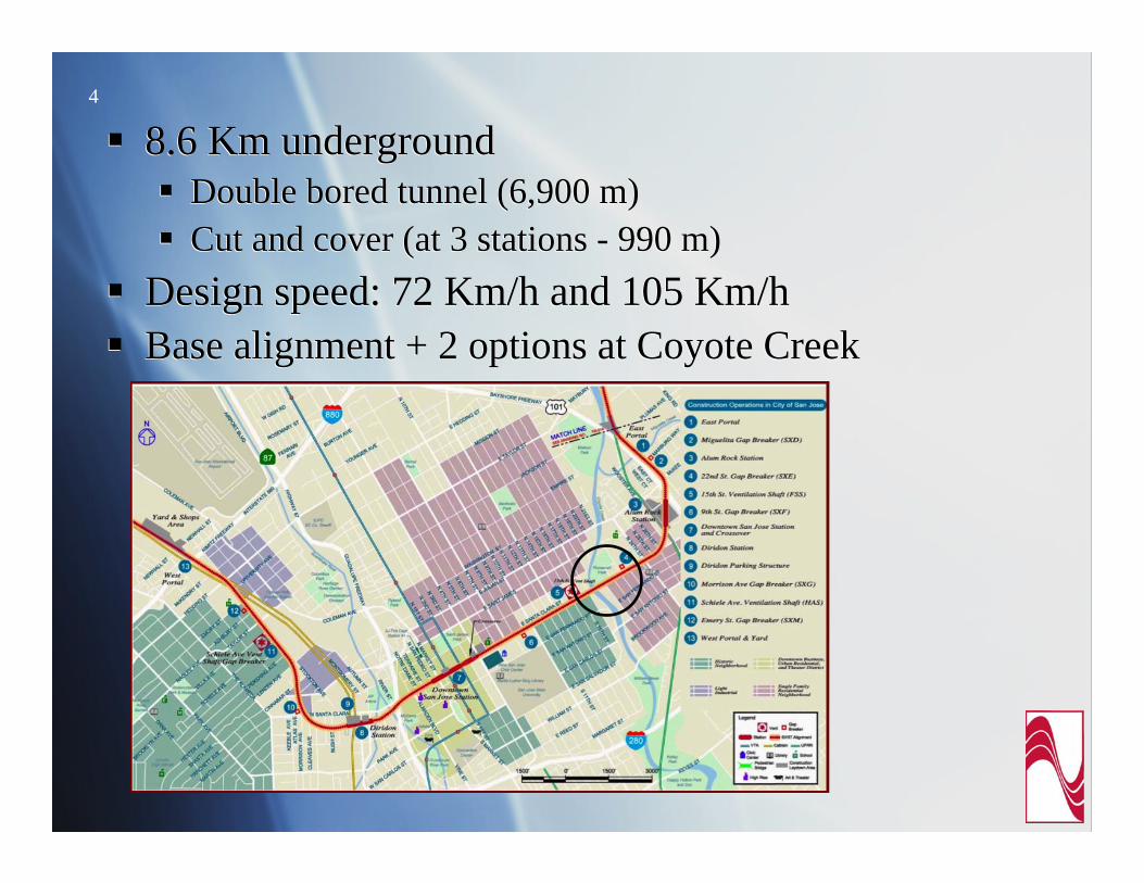
Preliminary evaluation of impacts and mitigation options
Mitigation options considered:Highly resilient direct fixation fastener (HRDF)Rail suspension fastener (RSF)Isolated slab track (IST)Floating slab track (FST)
Additional study of mitigation optionsResiliently supported tie (RST)High attenuation RST (HARST)
6
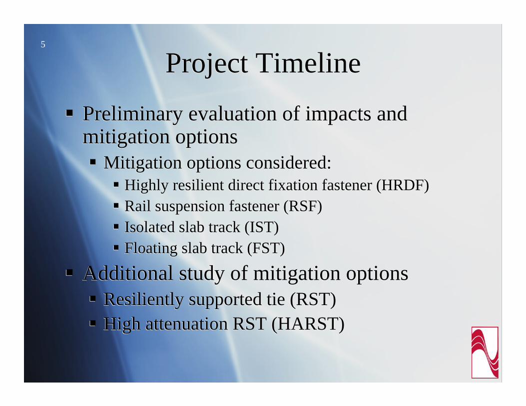
Projection ModelProjection ModelMethodology follows the FTA procedure for detailed analysisVibration: three main components plus adjustments
Groundborne noise
Methodology follows the FTA procedure for detailed analysisVibration: three main components plus adjustments
Groundborne noiseLv = Lfd + TM lineal + Cbuilding+ Adjust. + Design Factor
LA = Lv + Krad + KA-wt
7
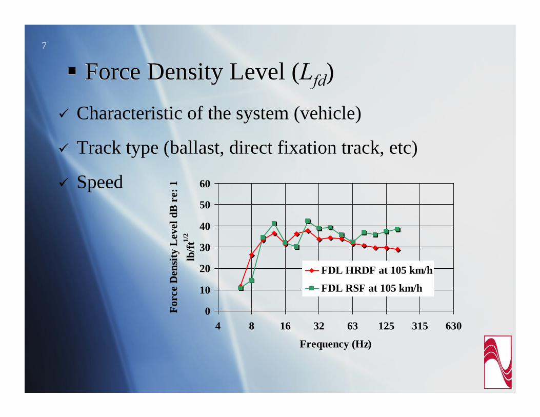
Force Density Level (Lfd)Force Density Level (Lfd)Characteristic of the system (vehicle)
Track type (ballast, direct fixation track, etc)
Speed
0
10
20
30
40
50
60
4 8 16 32 63 125 315 630
Frequency (Hz)
Forc
e D
ensi
ty L
evel
dB
re:
1
lb/ft
1/2
FDL HRDF at 105 km/h
FDL RSF at 105 km/h
8
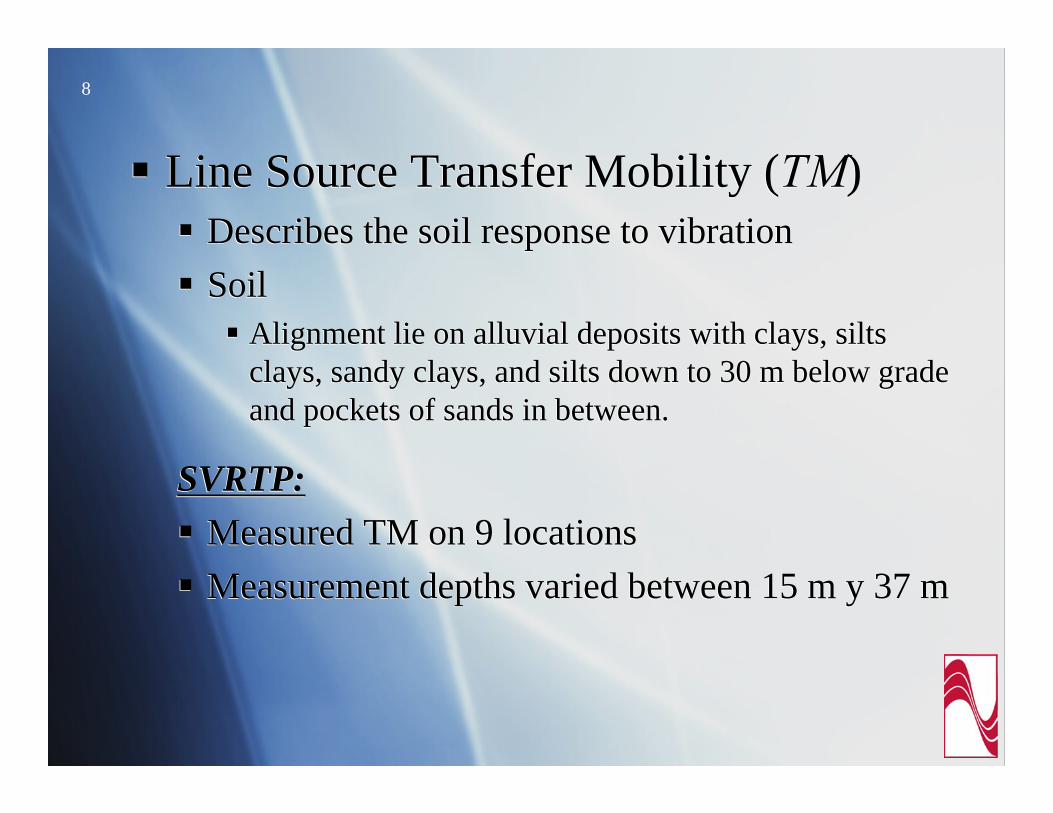
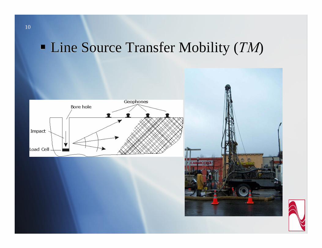
Line Source Transfer Mobility (TM)Describes the soil response to vibrationSoil
Alignment lie on alluvial deposits with clays, silts clays, sandy clays, and silts down to 30 m below grade and pockets of sands in between.
SVRTP:Measured TM on 9 locationsMeasurement depths varied between 15 m y 37 m
Line Source Transfer Mobility (TM)Describes the soil response to vibrationSoil
Alignment lie on alluvial deposits with clays, silts clays, sandy clays, and silts down to 30 m below grade and pockets of sands in between.
SVRTP:Measured TM on 9 locationsMeasurement depths varied between 15 m y 37 m

9
Line Source Transfer Mobility (TM)Borehole LocationLine Source Transfer Mobility (TM)Borehole Location
10
Line Source Transfer Mobility (TM)Line Source Transfer Mobility (TM)

11
Building Vibration Response (Cbuilding)Foundation coupling lossFloor resonance (amplification)
Building Vibration Response (Cbuilding)Foundation coupling lossFloor resonance (amplification)
-20
-10
0
10
20
4 8 16 31.5 63 125 250 500Frequency (Hz)
Rel
ativ
e V
ibra
tion
Lev
el -
dB
Single-Family 1st FloorSingle-Family 2nd FloorMulti-Family 2nd FloorTownHome 2nd Floor
12
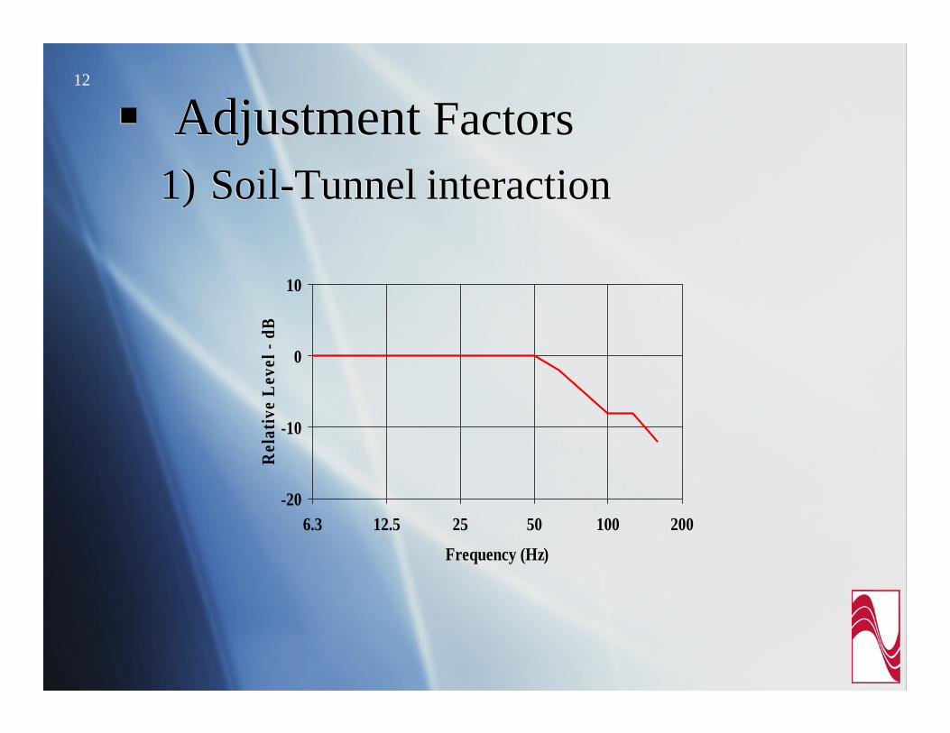
Adjustment Factors1) Soil-Tunnel interaction Adjustment Factors
1) Soil-Tunnel interaction
-20
-10
0
10
6.3 12.5 25 50 100 200
Frequency (Hz)
Rel
ativ
e L
evel
- dB
13
0
2
4
6
8
10
12
0 20 40 60 80 100Distance (m)
Rel
ativ
e V
ibra
tion
Lev
el -
VdB
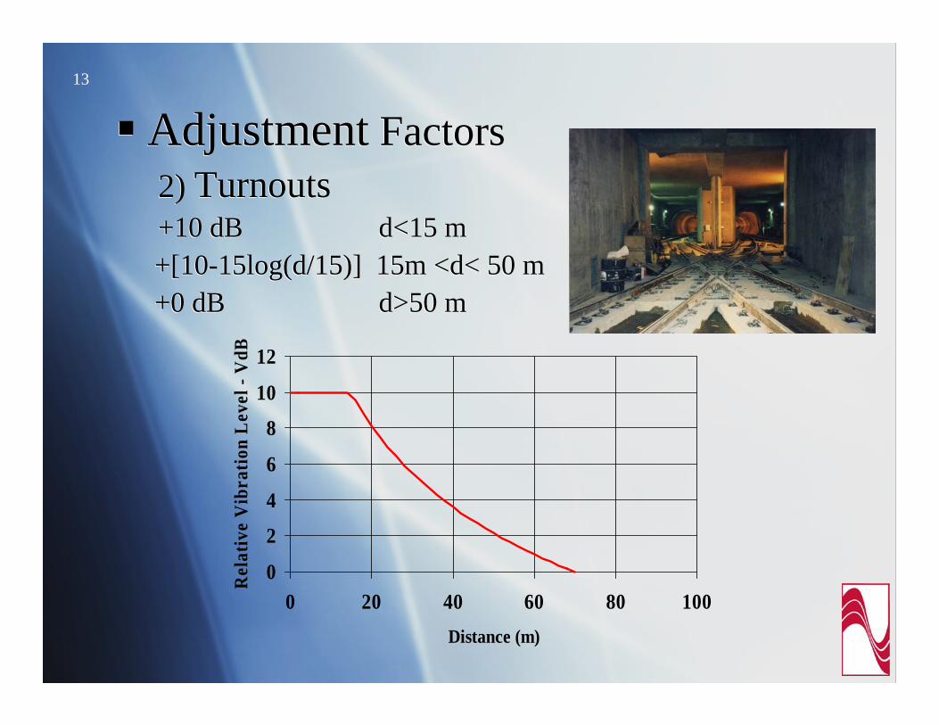
Adjustment Factors2) Turnouts+10 dB d<15 m+[10-15log(d/15)] 15m <d< 50 m+0 dB d>50 m
Adjustment Factors2) Turnouts+10 dB d<15 m+[10-15log(d/15)] 15m <d< 50 m+0 dB d>50 m

14
Vibration CriteriaVibration Criteria

15
Groundborne Noise CriteriaGroundborne Noise Criteria
Special Buildings
25 dBA25 dBAConcert Halls, TV Studios & Rec. Studios
48 dBA43 dBA40 dBACategory 3
38 dBA30 dBAAuditoriums
45 dBA35 dBATheaters
43 dBA38 dBA35 dBACategory 2
N/AN/AN/ACategory1
Infrequent Events
Occasional Events
Frequent Events
Land Use Category

16
Analysis ResultsAnalysis ResultsGroundborne vibration levels below criteriaGroundborne vibration levels below criteria
1020
3040
50
60
70
80
4 8 16 31.5 63 125Frequency (Hz)
Vib
ratio
n V
eloc
ity L
evel
- R
e 10
μin
Multifamily 2nd levelSingle Family raised floor 1 storyFire Station
No Vib. mitigationmeasures necessary

17
Analysis Results (cont…)Analysis Results (cont…)48 buildings (132 individual units) with potential for groundborne noise impact48 buildings (132 individual units) with potential for groundborne noise impact
0
10
20
30
40
50
60
6.3 10 16 25 40 63 100 160 250Frecuency (Hz
Multifamily 2nd levelFire StationSingle Family raised floor 1sto
18
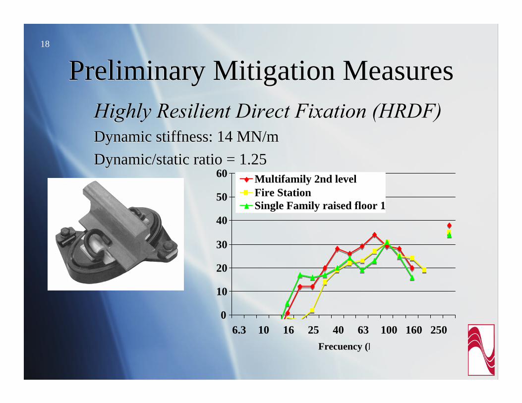
Preliminary Mitigation MeasuresPreliminary Mitigation MeasuresHighly Resilient Direct Fixation (HRDF)Dynamic stiffness: 14 MN/m Dynamic/static ratio = 1.25
Highly Resilient Direct Fixation (HRDF)Dynamic stiffness: 14 MN/m Dynamic/static ratio = 1.25
0
10
20
30
40
50
60
6.3 10 16 25 40 63 100 160 250Frecuency (H
Multifamily 2nd levelFire StationSingle Family raised floor 1
19
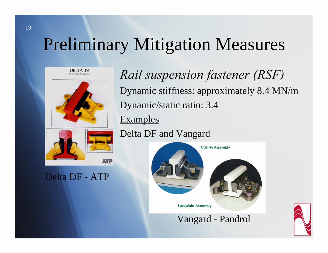
Preliminary Mitigation MeasuresPreliminary Mitigation MeasuresRail suspension fastener (RSF)Dynamic stiffness: approximately 8.4 MN/mDynamic/static ratio: 3.4 ExamplesDelta DF and Vangard
Rail suspension fastener (RSF)Dynamic stiffness: approximately 8.4 MN/mDynamic/static ratio: 3.4 ExamplesDelta DF and Vangard
Delta DF - ATP
Vangard - Pandrol

20
Preliminary Mitigation MeasuresPreliminary Mitigation MeasuresRail suspension fastener (RSF)(cont.)Rail suspension fastener (RSF)(cont.)
0
10
20
30
40
50
60
6.3 10 16 25 40 63 100 160 250Frecuency (H
Multifamily 2nd levelFire StationSingle Family raised floor 1st

21
Preliminary Recommendations on Vibration Mitigation
Preliminary Recommendations on Vibration Mitigation
22
Additional Mitigation Measures Evaluated
Additional Mitigation Measures Evaluated
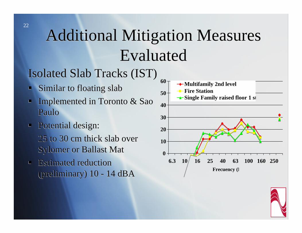
Isolated Slab Tracks (IST)Similar to floating slabImplemented in Toronto & Sao PauloPotential design:25 to 30 cm thick slab over Sylomer or Ballast MatEstimated reduction(preliminary) 10 - 14 dBA
Isolated Slab Tracks (IST)Similar to floating slabImplemented in Toronto & Sao PauloPotential design:25 to 30 cm thick slab over Sylomer or Ballast MatEstimated reduction(preliminary) 10 - 14 dBA
0
10
20
30
40
50
60
6.3 10 16 25 40 63 100 160 250Frecuency (H
Multifamily 2nd levelFire StationSingle Family raised floor 1 st

23
Additional Mitigation Measures Evaluated
Additional Mitigation Measures Evaluated
High Attenuation RST developed for Metro Hong Kong
High Attenuation RST developed for Metro Hong Kong
Wider block
Thicker Pad
Wider block
Thicker Pad

24 BART adopted resiliently supported half-tie (RST) as their design standard
Additional study was needed to evaluate a rail support track that:
Complies with their standard (RST), andReduce groundborne noise impacts
BART adopted resiliently supported half-tie (RST) as their design standard
Additional study was needed to evaluate a rail support track that:
Complies with their standard (RST), andReduce groundborne noise impacts
Concrete block
Rubber boot
Block:640mm x 260mm x 200 mm
Boot 12 mm thickness

25
Additional Parametric StudyAdditional Parametric StudyGoal: To determine if a single track system could mitigate ALL groundborne noise impacts
Numerical model:Discrete rail support Vehicle ModelParallel impedance modelTunnel invert forces
Goal: To determine if a single track system could mitigate ALL groundborne noise impacts
Numerical model:Discrete rail support Vehicle ModelParallel impedance modelTunnel invert forces

26
Additional Parametric StudyAdditional Parametric StudyTrack Support Systems Evaluated:
RST Original (pad stiffness 98 MN/m, mass block 82 kg) RST STD (“finned boot”, pad stiffness 44 MN/m, mass block 82 kg)HARST (High Attenuation RST, pad stiffness 22 MN/m, mass block 109 kg)HARST_SP (softer pad, pad stiffness 11 MN/m, block mass 109 kg)HRDF (pad stiffness 14 MN/m)
Track Support Systems Evaluated:RST Original (pad stiffness 98 MN/m, mass block 82 kg) RST STD (“finned boot”, pad stiffness 44 MN/m, mass block 82 kg)HARST (High Attenuation RST, pad stiffness 22 MN/m, mass block 109 kg)HARST_SP (softer pad, pad stiffness 11 MN/m, block mass 109 kg)HRDF (pad stiffness 14 MN/m)

27
ModelsModelsDiscrete Rail Support
Exact solutions of the Bernoulli-Euler model for discretely supported beamsIdeal spring-mass system
Truck ModelTruck represented by a 22 DOF system of wheel, axle, inertia block, motor, gear box, break and 1/2 car body
Discrete Rail SupportExact solutions of the Bernoulli-Euler model for discretely supported beamsIdeal spring-mass system
Truck ModelTruck represented by a 22 DOF system of wheel, axle, inertia block, motor, gear box, break and 1/2 car body
28
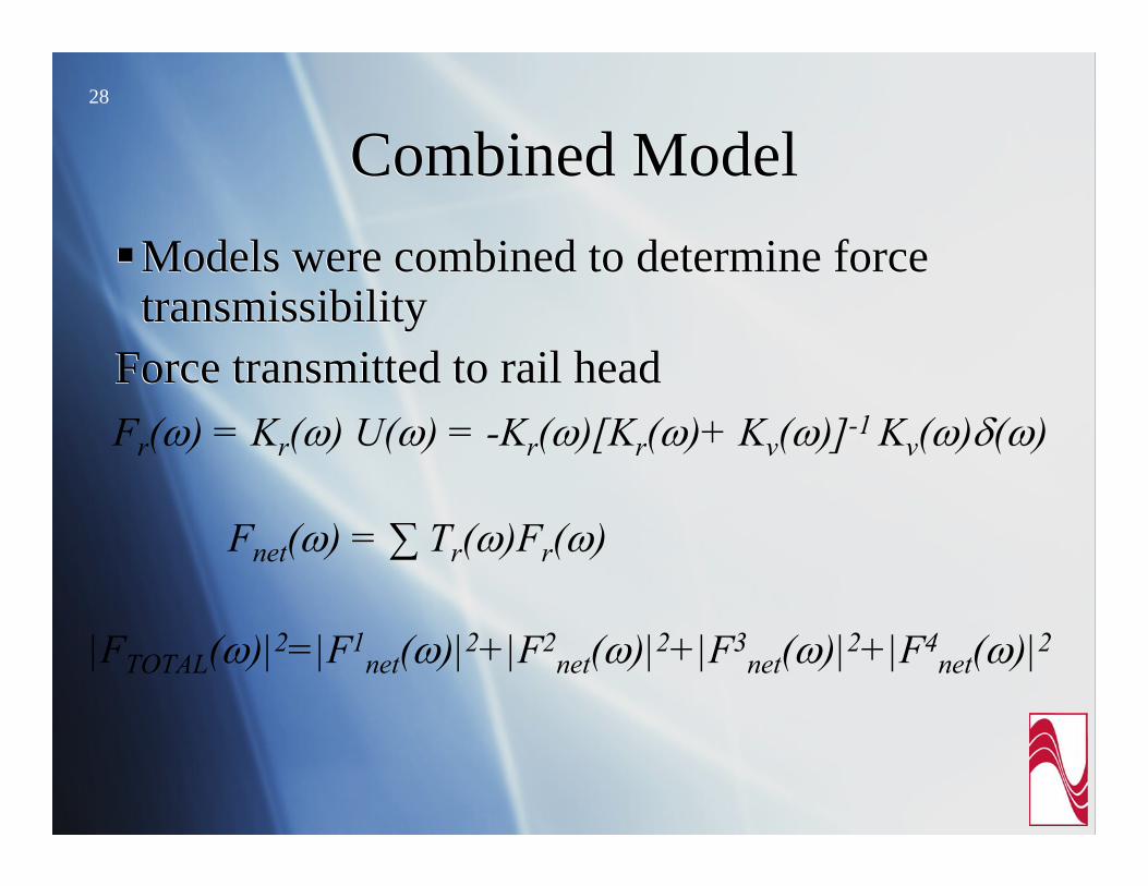
Combined Model Combined Model Models were combined to determine force transmissibility
Force transmitted to rail head
Models were combined to determine force transmissibility
Force transmitted to rail headFr(ω) = Kr(ω) U(ω) = -Kr(ω)[Kr(ω)+ Kv(ω)]-1 Kv(ω)δ(ω)
Fnet(ω) = ∑ Tr(ω)Fr(ω)
|FTOTAL(ω)|2=|F1net(ω)|2+|F2
net(ω)|2+|F3net(ω)|2+|F4
net(ω)|2

29
Model SchematicModel Schematic
Complete SimplifiedComplete Simplified
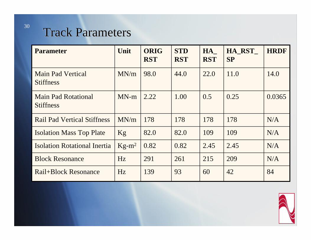
30Track ParametersTrack Parameters
84426093139HzRail+Block Resonance
N/A209215261291HzBlock Resonance
N/A2.452.450.820.82Kg-m2Isolation Rotational Inertia
N/A10910982.082.0KgIsolation Mass Top Plate
N/A178178178178MN/mRail Pad Vertical Stiffness
0.03650.250.51.002.22MN-mMain Pad Rotational Stiffness
14.011.022.044.098.0MN/mMain Pad Vertical Stiffness
HRDFHA_RST_SP
HA_RST
STD RST
ORIG RST
UnitParameter

31
Expected Reduction LevelsExpected Reduction LevelsResults of the simplified model (re: ORIG_RST)Results of the simplified model (re: ORIG_RST)
-30
-20
-10
0
10
4 8 16 31. 63 125 250 500Frecuency (Hz)
RST_STDHARSTHARST_SPHRDF

32 ConclusionsConclusionsA combination of highly resilient direct fixation fastener and rail suspension fasteners could be a viable solution to eliminate groundborne noise impacts.The parametric analysis indicates that high attenuation resiliently supported track with softer boot and pad HARST_SP could be a uniform solution for the project. However, before adoption by the Project, results will be validated with field measurements.
A combination of highly resilient direct fixation fastener and rail suspension fasteners could be a viable solution to eliminate groundborne noise impacts.The parametric analysis indicates that high attenuation resiliently supported track with softer boot and pad HARST_SP could be a uniform solution for the project. However, before adoption by the Project, results will be validated with field measurements.

33
AcknowledgeAcknowledge
Bay Area Rapid Transit (BART)HMM/BechtelBay Area Rapid Transit (BART)HMM/Bechtel