Embed Size (px)
DESCRIPTION
Â
Citation preview
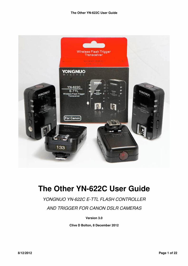
The Other YN-622C User Guide
8/12/2012 Page 1 of 22
The Other YN-622C User Guide YONGNUO YN-622C E-TTL FLASH CONTROLLER
AND TRIGGER FOR CANON DSLR CAMERAS
Version 3.0
Clive D Bolton, 8 December 2012
The Other YN-622C User Guide
8/12/2012 Page 2 of 22
INTRODUCTION What we know gets in the way of what we could know. I have used Canon’s Flash Control menus for 5 years, appreciating being able to control remote flashes from the camera. Well, sort of. Canon has been using an optical pulse “wireless” command system for off-camera flashes, which works within a limited set of conditions. Pixel released their King triggers to remove this limit, but their development was truncated. However, kudos to Pixel for pioneering this category of trigger/controller. Now we have the Yongnuo YN-622C which seems to fulfil the promise of a full implementation of Canon flash technologies over a radio link. It seems that Yongnuo has not only achieved this objective, but has added a wide range of triggering and photographer-friendly capabilities. Yongnuo have a range of hot-shoe flashes, with a reputation for unreliability. The design engineer for this device looks like single-handedly rescuing the brand. The YN-622C is a transceiver type radio device designed to go between a camera and one or more off-camera flashes, to provide:
• E-TTL, FEC & HSS off-camera triggering • Radio control of off-camera flashes from camera flash control menus • General-purpose triggering
There is much (unnecessary) debate about the merit of TTL flash exposure versus Manual power levels. Each method has its place, and photographers who understand the technologies can get predictable results. The YN-622C is a tool for both approaches. One part of Canon’s E-TTL is often misunderstood – Ratios. It is more than setting an FEC or EV adjustment on two flash groups. That still leaves distance, height, angle, relative powers, uneven ambient etc that can make a substantial difference. Canon’s ratio evaluates the actual contribution to the image of each group of flashes, and sets the level accordingly. It is much more accurate than the EV method. The YN-622C implements the genuine Canon technology in the camera. The YN-622C does not provide for firmware updates by the user. Canon Wireless Master/Slave is not available, being replaced by the 622 procedures. The transceiver buttons are hard to find by touch, and are sensitive to accidentally changed settings. Only flashes in group C can be disabled remotely. It is not a significant list of drawbacks. An examination of the case and internal components reveals a high-quality assembly. The case appears firm. I anticipate a good life expectancy. Because the YN-622C is designed primarily to implement Canon technologies, a thorough knowledge of both camera and flash manuals is helpful. Each camera model has its own variations. My verdict: versatile, complex, well-made, suitable for many jobs, and low-priced. Buy it. The author has no association with the manufacturer other than as a paying customer. Some additional samples were received; thanks, Yongnuo. The main testing equipment was EOS 50D and 7D; Speedlites 580EX II, 430EX II and 550EX; Yongnuo YN-266C triggers; Pixel Soldier as a radio shutter release.
The Other YN-622C User Guide
8/12/2012 Page 3 of 22
CONTENTS Introduction Contents Glossary Camera compatibility Type A – Camera menu Control Type B – Flash button Control Type C - Sync Only Flash compatibility Class 1 – Camera-set ETTL and Manual Class 2 – Camera-set ETTL, flash Manual Class 3 – Camera-set ETTL, no manual Class 4 - Sync Only Class 5 - Studio Strobes Getting Started Transmitter on Type A Camera Remote Flashes On-Top Flash PC-sync Flash Factory Reset Testing lighting setup Using a Light Meter First Shots YN Remote & Mix Modes Remote Control Mix Control More creative scenarios Canon Flash Control Menus E-TTL Mode Type A cameras Type B cameras Ratio Flash Exposure Compensation FEC Flash Exposure Lock FEL Flash Exposure Bracketing FEB
Manual Mode Remote Manual On-flash Manual Multi Mode (Stroboscopic) Shutter Sync Modes First Curtain Second Curtain Fast-Shutter Sync Simple Trigger Camera Features Ambient-only Shot High-speed Continuous Shooting Live View Modelling Light Flash features Flash zoom / coverage LCD Display Pilot Indicator 622 Features AF-assist beam Sleep Wakeup Status Indicator Group Indicators Using Type B Cameras Using Type C Cameras Suggestions Trouble Shooting Other Resources Specifications
Glossary Hot-shoe, Hot-foot, Cold-shoe: The hot-shoe is the accessory fitting on top of camera and transceiver. The hot-foot goes into the hot-shoe, e.g. bottom of a flash or transceiver. A cold-shoe holds a hot-foot without making contact with the pins. Transmitter (TX, Controller): The transceiver when mounted on the camera hot-shoe. (Transceiver will still act as a Receiver to another transceiver on the same channel.) Receiver (RX, Slave): The transceiver when used to connect a flash by hot-shoe or by a PC-sync cable. Remote Flash: A flash connected to a Receiver, by hot-shoe or by cable. On-top flash: A hot-shoe flash mounted on the Transmitter. It has some special features. 622: a convenient abbreviation for a YN-622C Transceiver.

The Other YN-622C User Guide
8/12/2012 Page 4 of 22
CAMERA COMPATIBILITY
Type A Camera – Camera Menu Control (2007 and on) Provides remote control of flash settings on class 1 flashes: Flash Mode (E-TTL with FEC, Manual with global level); Shutter Sync (1st curtain, 2nd curtain, HSS/Supersync); Firing groups (E-TTL Ratios, Manual levels); Zoom control; Channels.
• 1D III, 1Ds III, 1D IV (ID X not yet tested) • 5D II, 5D III, 7D (6D not yet tested.) • 40D, 50D, 60D • 450D XSi, 500D T1i, 550D T2i, 600D T3i, 650D T4i • 1000D XS, 1100D T3 • EOS-M
Provides as above except for Firing Groups (E-TTL or Manual) and Channels. • G12, G15, G1X, SX20 IS, SX30 IS, SX40 HS, SX50 HS
Type B Camera – Flash Button Control (prior to 2007) ETTL with FEC, Manual output levels, HSS and Supersync.
• 1D, 1D II (A bug with 1D series was fixed in September 2012) • 5D • 10D, 20D, 30D • 300D D-Rebel, 350D XT, 400D XTi
Type C Camera - Sync only Standard hot-shoe - Synchronised Fire!
• Supports single-contact hot-shoe cameras. • Includes many Nikon and other standard ISO hot-shoe cameras.
FLASH COMPATIBILITY Most flashes with a standard hot-shoe are “compatible” - they can be triggered synchronously. (The 622 is rated at only 6 volts on the trigger contact of its hot-shoe. The PC-sync connection can withstand 300 volts.) But the YN-622 is bought for its control abilities with a type A camera. A bit of relevant Speedlite history -
1. There was an Accessory shoe on camera to mount a device, and a centre-pin contact to fire the flash. All settings made on-flash. The camera did not know what they were.
2. More pins were added, and TTL, A-TTL, E-TTL and E-TTL II were developed as the key flash technology. The camera became more aware of flash settings. Settings still on-flash.
3. Canon implemented an off-camera system using a Master flash to drive one or more slaves using light-pulse coding. The camera was taught to read the flash settings, and act accordingly. FEC was added to the camera. There was no provision on the camera for setting Manual output levels, so there was no need to implement a path in the flash's hot-foot. Settings still on-flash.
4. A better interface was required, and in-camera. Canon designed the flash control menus so that for the first time, ALL settings could be read from itself rather than the flash. This meant major design requirements for the flashes. All flash settings needed to be digital. (e.g. The Wireless switch Off/Master/Slave had to go - the 3-position could not be moved digitally, and must not be allowed to indicate a setting that was not in force.) A path through the flash hot-foot to the processor had to be created which could set, not just read the flash settings. Settings could now be made either on-camera, or on-flash for legacy flashes.
So, the only flashes which can be controlled by flash menus are ones that have the required communication through the hot-foot. (The light-pulse receiver system is not involved.)

The Other YN-622C User Guide
8/12/2012 Page 5 of 22
Class 1 – Camera-set E-TTL and Manual Levels Using Flash Control menus: Flash mode (ETTL, M, Multi); Zoom; Sync mode (1st, 2nd, HSS); ETTL functions (FEC, FEB and Ratio); Remote Manual levels. Brand HSS No HSS Canon 430EX II, 580EX II, 600EX-RT Nissin Di866 II Yongnuo YN-568EX YN-465, YN-467, YN-467 II, YN468,
YN-468 II, YN-565 II, YN-565EX
Class 2 – Camera-set E-TTL; Flash-set Manual Levels Set on flash: Flash mode (ETTL, M, Multi); Zoom; Manual levels Using Flash Control menus: Sync mode (1st, 2nd, HSS); ETTL (FEC, FEB, FEL and Ratio). Brand HSS No HSS Canon 430EX, 550EX, 580EX Metz 48 AF-1, 58 AF-2 Nissin Di866 Di622 II Sigma EF 530 DG Super EF 500 DG Super Sunpak PZ42X
Class 3 – Camera-set E-TTL; Manual Levels not provided Brand HSS No HSS Canon 220EX, 270EX II, 320EX, 380EX, 420EX
Class 4 – No E-TTL provided; Flash-set Manual Levels; Sync Only Synchronised up to 1/8000S (Supersync), limited by camera and strobe, otherwise synchronised to maximum 1/250s.
• Includes various hot-shoe flashes, including single-contact flashes. • A hotshoe- mounted flash with only the centre pin effective will receive only a 1st-curtain
sync signal. • A flash connected by a PC-sync cable (including through a PC to Hot-shoe adapter) will
receive a 1st-curtain, 2nd-curtain or pre-shutter sync signal. Brand Model Canon 540EZ (updates LCD info.) MeiKe 940 Vivitar 285, 285HV IF trigger voltage is below 12 volts Yongnuo YN460, YN460-II, YN560, YN560-II, YN560EX
Class 5 - Studio Strobes Actual feedback by users on Supersync, gleaned from online sources: No = no usable light contributed to image. Usable = some usable light contributed with some settings, probably with significant gradient. Ok = Usable light over most appropriate settings to 1/8000th, minor gradient.
• Alien Bee 400 – no; AB 800 – usable; AB 1600 – ok. • Bowens Travelite – no. • Einstein E640 – no. • Elinchrom D-Lite 2 – no. • Jinbei Discovery 1200w, Jinbei Digital Pioneer III 600w – ok. • Mettle 600 – usable. • Calumet Genesis 300B - ok
The Other YN-622C User Guide
8/12/2012 Page 6 of 22
GETTING STARTED Important
• Keep transceivers dry and out of explosive situations. • Turn off power on camera, transceivers and flashes before connecting. • Check that all equipment is installed correctly in the hot-shoe. • Batteries – camera, flash, 622s – are critical. Recharge or replace as required. • Transceiver settings are saved automatically, including channel, lighting group, flash firing
mode and AF-assist firing. Some E-TTL parameters will not be saved, such as group fire ratio.
Transmitter on Type A Camera Install a 622 on the camera’s hot-shoe:
• Back the locking ring up to the transmitter case to withdraw the locking pin. • Mount the 622 in the camera’s hot-shoe. Press the foot firmly forward to ensure all contacts
are made securely. • Clamp the locking ring onto the hot-shoe. The locking pin will engage. • Press half-shutter or open External Flash control menu to activate as a transmitter.
Set up transmitter using camera menus: Keep the transmitter in Remote Control mode (the default mode). Flashes will comply with the settings in the camera’s Flash control / External flash function menu.
• Set Flash firing to Enable. • Select External flash function setting and set desired flash mode, zoom setting etc. • Enable wireless function and set firing group, fire ratio or flash output. (If the Wireless
function is disabled, the firing group consists of All (A+B+C), and all groups of flashes use the same global settings.
• Set a channel for the transmitter (CH1-CH4 only).using the Wireless function menu.
Remote Flashes Install each flash on the hot-shoe of a Receiver:
• Loosen the locking ring or lever on the flash to withdraw the locking pin. • Mount the flash on the 622. Press the foot firmly forward to ensure all contacts are secure. • Tighten the flash’s locking ring or lever. • Mount the 622 direct on a mini stand, or on a light stand using a cold-shoe adapter.
Turn on Receiver and set Channel and Group:
• Slide Receiver power switch to [ON]. The channel and group indicators light briefly. The Status indicator turns steady red. The flash may fire once when turning the 622 on or off.
• Set Receiver to the same channel as the Transmitter, using [CH SET]. The channel indicator will light for several seconds to indicate the current channel. Quickly press [CH SET] again to change the channel.
• Set the lighting group (A, B or C) for each flash using [GP SET] to produce the desired lighting control.
Turn Flash on
• Check that each flash indicates ready. • Press Pilot/Test on the flash.
The Other YN-622C User Guide
8/12/2012 Page 7 of 22
On-Top Flash A flash can be installed on the transmitter on top of the camera. It behaves much like a Remote flash, but there are differences:
• Supports E-TTL, Manual levels and Multi (stroboscopic) modes. • The On-top flash output settings follow Group A settings. • The On-top flash has no channel. It is effectively direct-connected to the camera. • The zoom setting is not controlled by the camera menu. It must be separately set on-flash
as auto or as a manual level. The zoom setting of the On-top flash can be different than off-camera flashes. E.g. Set the On-top flash zoom to Auto, so that it zooms with the lens. Using the camera flash control menu, set Manual zoom 24mm – 105mm so that off-camera flashes keep a constant setting.
• It may provide an AF-assist beam additional to the Transmitter’s AF-assist beam, if that is enabled.
PC-sync Flash First curtain, Second Curtain and Fast Shutter (Supersync) syncs are available.
Factory Reset If a transceiver seems erratic:
• Disconnect the 622 then turn it on. • Hold down [CH SET] plus [GP SET] at the same time. • The Status indicator will wink red-green alternately 3 times, then stay red. • Release the buttons. Factory defaults will be set.
Testing the Lighting Setup The setup can be tested to ensure that all devices are powered up and that the communication is working. In addition, actual lighting outputs can be metered if manual levels are being used.
• The [Test] button can awaken the flashes and test whether they can be triggered. • The test works through both hot-shoe and PC-sync cable. • If the flash does not wake, manually awaken it. • Use the PC-sync port to connect a flash which does not have the awakening function. • All 622s (in transmitter or receiver mode) on the same channel as the test unit will be
addressed, and those flashes in the “Test Group” will be fired. • An on-top flash will also fire if the 622 transmitter’s Lighting group is included in the test
group. • All the indicators go out when flash fires. • The Testing group is not the same as the Lighting group, or the Firing group which controls
ratios and levels. • To select a testing group, hold down [Test] and repeatedly press [GP SET] to cycle through
the seven testing groups. • To test all flashes, select All (A+B+C). • When the desired testing group is shown, release [Test]. The flashes in the selected group
will fire a test flash.
The Other YN-622C User Guide
8/12/2012 Page 8 of 22
Using a Light Meter • Set Manual levels (or Multi), either by Flash Control menus or by on-flash settings. • The test fire will be at the level as it is displayed on the LCD of the flash. • The test button will not change the setting of the flash. • If Remote control is being used, first press half-shutter to ensure that settings are applied • E-TTL will produce a pre-flash, which may confuse the light meter. • Trigger with any 622 on the same channel. It may be a hand-held one.
First Shots With the 622 transmitter in Remote Control mode, press [MENU] on the camera, and select Flash Control / External flash function setting.
• The 622 transmitter’s Status indicator will flash yellow and its CH and GP indicators will flash green to indicate transmitting. The 622 Receivers will flash red and its CH and GP indicators will flash green. They will stay in a live update state until the menu session ends.
• Select E-TTL II as flash mode. • When the off-camera flash settings match the camera’s menu, the AF-assist beam of the
receiver will wink twice to show that the change is successful. If the parameter which has been changed isn’t supported by the flash (such as hi-speed sync), this function will be abnormal.
• Half-shutter to focus, and on the flash screen the aperture and effective range etc. will be displayed.
• The AF-assist beam of the transmitter may assist focusing. • Ensure that the subject is in the effective flash range, and fully press shutter button to
shoot. • Enable the Wireless function menu to enable firing group control.
The Other YN-622C User Guide
8/12/2012 Page 9 of 22
YN REMOTE & MIX MODES The YN-622C can work in either of two modes – Remote or Mix. In Remote mode, the Type A camera’s flash control menus take priority over most on-flash settings. In Mix mode, the on-flash settings take priority. E-TTL and Manual can be mixed.
Remote Control Mode • The camera’s Flash Control menu settings take priority, and enforce settings on Class 1
flashes. • This is the Factory default mode. • The last-used setting is remembered during power-down. • Requires a Type A camera for Manual settings. • Channel indicator does not stay lit.
Examples: Camera + 622 + 580EXII (622 in Remote Mode; flash is in Group A enforced). Two remote 622 + 430EXII.
• Set Remote 622s to Group B. Set menu item Flash Mode to ETTL, with FEC if needed. Set Wireless/Firing Group to A:B. Set Fire Ratio to 1:3. The camera will call for pre-flash, evaluate power levels required, and produce a normal exposure from the two Group B flashes, with fill from the on-top flash. FEC and Ratio can be controlled from camera.
• Set one remote 622 to Group B and the other to Group C. Set Flash Mode to Manual. Set Wireless/Firing Group to A:B C. Set Group Outputs for A-1/32, B-1/8 and C-1/4. Use B as main, C as background, A as on-camera fill. Group outputs can be set and adjusted remotely as required.
Mix Control Mode Creative lighting scenarios can be implemented by switching the 622 system to Mix mode.
• Type A and B cameras may be used. • All Classes of flash may be used. • E-TTL / Manual / Multi flash modes may be mixed. • Flash settings take priority. Settings are made manually on each flash • To invoke Mix mode, hold down [CH SET] on the transmitter for 3-4 seconds until the
channel indicator winks 3 times. It will then stay lit. • To cancel Mix mode (the channel indicator will be lit), hold down [CH SET] on the
transmitter for 3-4 seconds until the channel indicator winks 3 times It will then be extinguished.
• The Remote/Mix setting is remembered by the individual unit on power-down. • Do not try to set or un-set Mix mode using the buttons on receivers. • The Flash mode of the transmitter will be locked in E-TTL mode. • Set each flash (including an on-top flash) to desired flash modes, E-TTL, Manual or Multi.
The settings of the flash take priority. • The camera can set only FEC, FEB, Ratio and Shutter sync. • If the shutter sync is set by the camera menu, the on-flash setting is ignored. A type B
camera defaults to hi-speed sync. • The camera’s zoom setting is disabled. • Any flash set to E-TTL will emit a preflash. If its mode is Manual or Multi, it won't.
The Other YN-622C User Guide
8/12/2012 Page 10 of 22
More Creative Scenarios Augmented ambient Indoor event photographers may use flashes high on light-stands and set to bounce light off the ceiling, or to provide hair- or rim-light. An on-top flash provides on-axis fill/main light for subject. Basic setup
• Camera menu set to Firing Group A:B C • Transmitter set to Mix mode. CH indicator shows steady green. • Receiver’s lighting groups set to B and C. • On-top Class 1 or 2 flash set on-flash to ETTL mode. • Remote Class 1 flashes set on-flash to Manual at say 1/8th power.
Remotely adjusting augmenting flashes in Mix mode
• Transmitter changed to Remote mode. • Select camera menu Manual mode and adjust output levels for B and C. • Transmitter changed back to Mix mode. • On-top flash re-set on-flash to ETTL mode.
Second shooter A second shooter can share the augmenting flashes. Either camera will trigger all 622s on the same channel, both on-top and off-camera flashes. Your on-top flash will zoom and fire in response to the other camera, Using the Walkabout two-channel technique may be useful also, when sharing flashes. Walk-About (APOAZ technique)
• On-top flash in ETTL and flashes in Manual to augment. • To be able to turn off triggering of augmenting lights, set remote 622s to say Channel 2. • Set Transmitter to CH 2 to use remote lights, and on-top flash will still fire. • Set Transmitter to CH 1 to use only on-top flash.
Remote mode with Class 2 or 3 flashes (Dan Kinzie technique) Instead of using Class 1 flashes in the basic setup above, use Class 2 or 3 flashes like the YN-560.
• Transmitter set to Remote mode. • Camera menu set to E-TTL mode. • The 560s set on-flash to a manual power level. • The on-top flash will adopt menu settings and produce an FEC-controlled exposure • The YN-560s will be triggered at their set levels, and will not respond to menu settings. • The maximum sync speed may be 1/250S. • Using a PC-sync cable with Class 1, 2 or 3 flashes and Class 4 Studio strobes can also be
used this way. • Class 1 flashes can be used on-shoe by buffering it from the remote control signals by
using a trigger-only (2-wire) adapter hot-shoe. Class 4 strobes with Independent Remote Control (David Ward technique)
• Place a 622 on the camera, with an on-top hot-shoe flash. • Place a 622 nearby and mount another type of trigger controller, like the Cybersync
Commander. • Mount strobes, e.g. Einsteins, on stands for augmented ambient or rim light. Connect a
Cybersync receiver to each. • The Cybersync provides easy remote control of strobes for adjusting power, turning on and
off etc, and the 622 provides triggering of the strobes and full control of any 622-mounted hot-shoe flashes.
The Other YN-622C User Guide
8/12/2012 Page 11 of 22
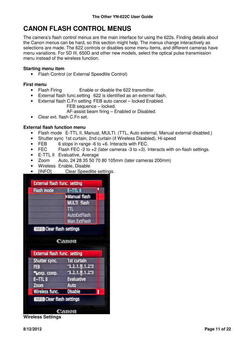
CANON FLASH CONTROL MENUS The camera’s flash control menus are the main interface for using the 622s. Finding details about the Canon menus can be hard, so this section might help. The menus change interactively as selections are made. The 622 controls or disables some menu items, and different cameras have menu variations. For 5D III, 650D and other new models, select the optical pulse transmission menu instead of the wireless function. Starting menu item
• Flash Control (or External Speedlite Control) First menu
• Flash Firing Enable or disable the 622 transmitter. • External flash func.setting 622 is identified as an external flash. • External flash C.Fn setting FEB auto cancel – locked Enabled. FEB sequence – locked. AF-assist beam firing – Enabled or Disabled. • Clear ext. flash C.Fn set.
External flash function menu
• Flash mode E-TTL II, Manual, MULTI. (TTL, Auto external, Manual external disabled.) • Shutter sync 1st curtain, 2nd curtain (if Wireless Disabled), Hi-speed • FEB 6 stops in range -6 to +6. Interacts with FEC. • FEC Flash FEC -2 to +2 (later cameras -3 to +3). Interacts with on-flash settings. • E-TTL II Evaluative, Average • Zoom Auto, 24 28 35 50 70 80 105mm (later cameras 200mm) • Wireless Enable, Disable • [INFO] Clear Speedlite settings.
Wireless Settings
The Other YN-622C User Guide
8/12/2012 Page 12 of 22
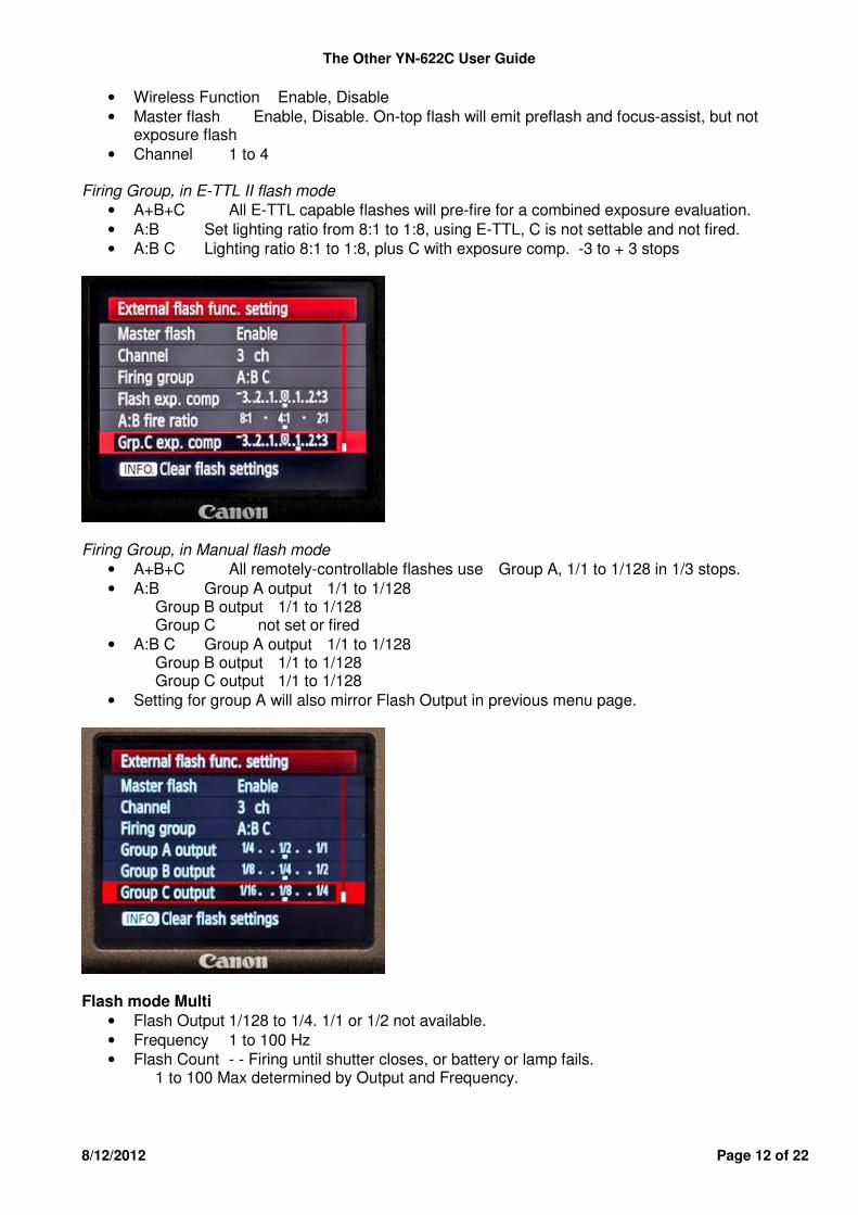
• Wireless Function Enable, Disable • Master flash Enable, Disable. On-top flash will emit preflash and focus-assist, but not
exposure flash • Channel 1 to 4
Firing Group, in E-TTL II flash mode
• A+B+C All E-TTL capable flashes will pre-fire for a combined exposure evaluation. • A:B Set lighting ratio from 8:1 to 1:8, using E-TTL, C is not settable and not fired. • A:B C Lighting ratio 8:1 to 1:8, plus C with exposure comp. -3 to + 3 stops
Firing Group, in Manual flash mode
• A+B+C All remotely-controllable flashes use Group A, 1/1 to 1/128 in 1/3 stops. • A:B Group A output 1/1 to 1/128
Group B output 1/1 to 1/128 Group C not set or fired
• A:B C Group A output 1/1 to 1/128 Group B output 1/1 to 1/128 Group C output 1/1 to 1/128
• Setting for group A will also mirror Flash Output in previous menu page.
Flash mode Multi
• Flash Output 1/128 to 1/4. 1/1 or 1/2 not available. • Frequency 1 to 100 Hz • Flash Count - - Firing until shutter closes, or battery or lamp fails.
1 to 100 Max determined by Output and Frequency.

The Other YN-622C User Guide
8/12/2012 Page 13 of 22
E-TTL MODE Automatic Adjustable Metering
Type A cameras Camera menus or buttons
• All (global), A:B (ratio), A:B C (ratio + FEC) • FEC +/- 2 stops, with on-flash FEC settings adding to the result. • E-TTL modes Evaluative or Average • E-TTL Flashes emit a pre-flash
Type B cameras Camera buttons
• All (global), no Canon ratio. • FEC +/- 2 stops, with additive on-flash FEC setting • E-TTL modes Evaluative or Average • E-TTL Flashes emit a pre-flash
Ratio Canon’s lighting ratio becomes available through the Firing Group settings, when Wireless mode is enabled. This is the true professional multi-preflash “effective reflected light” ratio, not an approximation.
• Ensure that the light output requirements are within the capability of the flashes, possibly by increasing ISO, changing distance to subject, etc.
• Flashes with different maximum outputs can be mixed. A:B Firing Group
• Set the lighting ratio from 8:1 to 1:8 (in 1/2-stop increments) • A “normal” subject exposure will be calculated. • This total exposure can be adjusted by the over-all FEC setting. • The effective reflected light from group A flashes (including on-top flash) and group B
flashes will be evaluated by the camera and transmitted to the flashes by the 622. • Group C does not fire.
A:B C Firing Group
• Set A:B ratio as above. • Set an FEC (-, 0 or +) for flashes in Group C.
Flash Exposure Compensation (FEC) The over-all flash exposure can be adjusted using the camera button, camera flash control menu, and the on-flash setting.
• FEC can be set in 1/3-stop increments within � 2 or � 3, depending on camera. • The total compensation is the flash FEC setting plus the camera menu setting. For
example, if the camera menu is set to -2, and the flash is set to +1, then exposure compensation will be -1.
Flash Exposure Lock (FEL) • Canon FEL is implemented.
The Other YN-622C User Guide
8/12/2012 Page 14 of 22
Flash Exposure Bracketing (FEB) • Set FEB in 1/3-stop increments within � 2 or � 3. • The zero point for FEB is adjusted by the global FEC setting. • The sequence of FEB is fixed at 0 � - � +, even when the on-flash setting is different. • The FEB function will be automatically cancelled after three shots are taken. • An E-TTL flash which does not support FEB can also be used.
MANUAL MODE
Remote Manual Levels Type A camera menus can remotely control Mk II Speedlites and YN flashes.
• All (global), groups A and B, or A, B and C. • Power levels 1/1 to 1/128, by Group • E-TTL Flashes do not emit a pre-flash
All Flashes (Global setting)
• Set Flash Mode to Manual. • Set Flash Output as required, 1/128 to 1/1 power level, in 1/3-stop increments. • Either, Set Wireless function to Disable, or Enable with Firing Group A+B+C.
Two and three lighting groups
• Set Flash Mode to Manual. • Ignore Flash Output: it will repeat group A setting. • Set Wireless function to Enable. • Set Firing Group to A:B (C will not fire) or A:B C. • Set each Group Output as required, 1/128 to 1/1 power level, in 1/3-stop increments. • On-top flash will fire at group A level, if Master Flash is enabled.
On-Flash Manual Levels Type A, B or C cameras can trigger flashes where the output level has been set on-flash.
• Flash connected by PC-sync cable. • Power levels set on individual flash. • E-TTL Flashes do not emit a pre-flash
The Other YN-622C User Guide
8/12/2012 Page 15 of 22
MULTI (STROBOSCOPIC) MODE Usage is similar to Remote Manual and On-flash Manual. Stroboscopic mode is particularly effective with a highly-reflective subject against a dark background. Consider using a tripod, remote switch and external battery pack.
• Set Flash Mode to Multi. • Set desired Flash output, Frequency and Flash count, as provided by the camera. • Flash Count x Hz = minimum shutter duration. • Limit rapid use and allow at least 15 minutes rest between frequent bursts. • E-TTL Flashes do not emit a pre-flash
SHUTTER SYNC MODES
First Curtain (Front Curtain) • The “normal” flash sync. • ETTL, Manual and Multi Flash modes
Second Curtain (Rear Curtain) The flash fires right before the shutter closes, giving the appearance of forward motion.
• A long shutter speed or bulb needs to be used. • If “Wireless flash” is enabled, Second curtain sync will be disabled by the camera. • ETTL and Manual Flash modes are available, including off-camera.
Fast-Shutter Sync High-Speed (HSS or FP)
• ETTL and Manual Flash modes, syncs with all shutter speeds up to 1/8000th Sec • The camera must support HSS. • If the hot-shoe flash does not support HSS, the max sync speed is 1/250S or less.
Supersync (Flash Burn) • Works with many hot-shoe and studio flashes, up to 1/8000th Sec • Connection only through PC-sync port. A PC-sync cord required. • Max. 300v trigger voltage. • Set camera’s shutter sync as Hi-speed sync. • Use manual exposure or shutter-priority mode • For type C camera, the max PC sync speed is 1/250s or less. • A flash on the hot shoe and another connected to the PC-sync port can be used at the
same time.
Simple Trigger • Single-contact camera & single-contact flash triggering (max sync speed is 1/250s)
The Other YN-622C User Guide
8/12/2012 Page 16 of 22
CAMERA FEATURES
Ambient-only shot • Turn transmitter off. 622 settings are remembered when powered up again. • Or, use type A camera menu Flash Firing – Disable.
High-speed Continuous Shooting • Trigger keeps up with camera. (Tested at 6.5 fps.) • A Flash battery pack is recommended for maintaining flash output consistency.
Live View • Silent Mode must not be enabled, as Canon then prevents flash from firing.
Modelling Light • Works as designed. All flashes fire, including on-top flash.
FLASH FEATURES
Flash Zoom (Flash Coverage) Canon provided a flash head zoom to provide lighting just wide enough to cover the lens’s field of view. Consider the zoom as a light modifier, for efficiency or artistic reasons, or because the flashes may be off-camera and lens zoom is irrelevant. The 622 provides more flexibility than Canon’s implementation. This may be affected by Canon’s rules - Wide panel extended: 14mm; Head in Bounce on Auto: --mm; Head in Bounce on Manual: as set; Auto-adjust for sensor size enabled. Zoom Lock An individual flash under remote control can have its zoom setting locked so that it is not controlled by the camera’s zoom menu setting.
• Hold down [CH SET] on a 622 Receiver for several seconds until the channel indicator stays lit. (This is the same as setting mix control on a transmitter.)
• Adjust the flash zoom setting with the flash control panel (automatic or manual). • Hold down [CH SET] for several seconds to cancel. The channel indicator will go out.
Zoom and Remote Control
• Remote Control – camera zoom settings apply. Auto; Manual 24 to 105mm (or 200mm). • With automatic setting, focal length of the flash may change with lens focal length. • With manual setting, focal length of the flash supports manual setting within 24-105MM.
Zoom and Mix Control
• The camera’s zoom menu setting is disabled. • Set each flash’s zoom setting on-flash – Auto, Manual 24 to 105mm (or 200mm).
LCD display • Flash zoom, focal length, ISO, shutter speed, FE Lock, HSS indicators change with
settings.
Pilot Indicator • Individual test fire works.
The Other YN-622C User Guide
8/12/2012 Page 17 of 22
622 FEATURES
AF-Assist Beam When using Autofocus under low-light, the AF-assist beam can be emitted automatically to make it easier to autofocus.
• The 622 acting as Transmitter will emit the beam when required by the camera. • An on-top flash which has an AF-assist beam function can also emit at the same time. • Neither a 622 Receiver nor an off-camera flash on the receiver will emit the beam. • The LED laser provides a bright, clear pattern with a good range. There is no health risk. • The AF-assist beam can be enabled or disabled in a 622 mounted on the camera by using
the camera’s “External flash C.Fn settings”. The setting is saved automatically in the 622. • When a 622 is mounted on a camera, the camera menu will conform to that 622’s AF-beam
setting.
Sleep Wakeup • On ½ shutter or [Test]. • Flash must be mounted on hot-shoe, not PC-sync cord. • Flash must have a wake-up facility.
Status Indicator • Power-up/self-test/initializing - red flash for several seconds, plus selected CH and GP
indicators. • Standby - steady red. • Battery low – on startup or half-shutter; Status will rapidly wink Red/Green, and the CH and
GP indicators will dimly wink also. If the voltage is too low, the 622 will turn off automatically.
• 622 Transmitter communicating – green wink. • 622 Receiver communicating – red wink.
Group Indicators Lighting Groups
• Each 622 belongs to one lighting group, A, B or C. The default is A. • The assigned lighting group is remembered on power-down. • The assigned lighting group is indicated briefly on start-up, and when [GP] is pressed. • This behaviour includes a 622 mounted on the camera. • An on-top flash has no group indication. It is deemed to be in group A, and uses A’s
settings. Testing Groups
• Press [Test] and [GP] to display the groups that will be fired during a test (A, B, C, AB, AC, BC, ABC). The default is ABC – all.
• An on-top flash will be included in its 622’s lighting group, which may be group A, B or C. Firing Group
• The Firing group is set using the camera’s External Flash settings. • When a 622 is activated as a transmitter (pressing half-shutter, or opening External flash
menu), the group indicators will wink, indicating not the Lighting group but the Wireless Firing group set in the menus.
None Wireless disabled (stand-alone mode) A LED Wireless enabled, Firing group A+B+C B LED Wireless enabled, Firing group A:B C LED Wireless enabled, Firing group A:B C

The Other YN-622C User Guide
8/12/2012 Page 18 of 22
USING TYPE B CAMERAS As there is no flash control menu, some functions will be restricted.
• Install a 622 in the camera’s hot-shoe, so that it auto-selects Transmitter mode. • Enable Mix control mode on the transmitter. ([CH SET] for several seconds.) • Use [CH SET] to set the communication channel. • Press half-shutter. The Status indicator winks green. Press [GP SET] to set firing groups to
be used. • Set the required flash mode (E-TTL, Manual, Multi) using the flash’s control panel. • E-TTL mode supports automatic flash, including FEC and FEB. It defaults to hi-speed sync. • Manual (M) mode requires flash output to be manually set on-flash. It defaults to hi-speed
sync. • Multi mode requires several parameters to be set on-flash.
USING TYPE C CAMERAS Manually set the Flash Output
• Set the Transmitting group(s) for the 622 transmitter. Hold down [Test] and repeatedly press [GP SET] to cycle through the seven groups. When the desired group is shown, release [Test]. This is the same procedure as selecting a testing group for the [Test] button.
• Set the Flash mode to Manual (M) using the flash’s control panel. • Does not support hi-speed sync or other E-TTL functions. • Max speed sync is 1/250s or less.
SUGGESTIONS Batteries Alkaline batteries start at 1.5 volts and hold their voltage until the very end. Rechargeables at 1.2 volts are already 20% down, and approaching the threshold for the 622. Alkaline characteristics are well suited to this type of device, with a 60-hour standby time. (NiMH batteries are great as flash batteries, being capable of a rapid discharge into the capacitor.) Battery Orientation Flashes are often used in low light. It can be hard to read the embossed polarity markers at the bottom of the recess. Use a silver marker pen to highlight the two [+] markers. Camera’s Custom Menu Set up the Flash Control menu as a Custom Menu item, and make the Custom Menu the first one up. Supersync Images Supersync images may benefit from the application of the Gradient tool in post-processing. Wireless Mode Setting Keep this setting at Enabled, and disable it only when 2nd curtain sync is required. (5D II and IIII, and possibly others, change the sync timing if Wireless is Disabled.)
The Other YN-622C User Guide
8/12/2012 Page 19 of 22
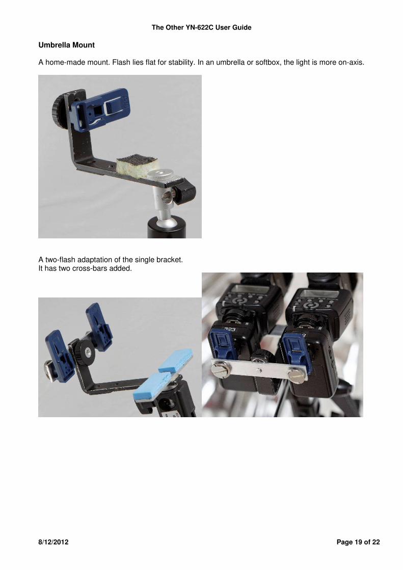
Umbrella Mount A home-made mount. Flash lies flat for stability. In an umbrella or softbox, the light is more on-axis.
A two-flash adaptation of the single bracket. It has two cross-bars added.
The Other YN-622C User Guide
8/12/2012 Page 20 of 22
TROUBLE SHOOTING Full-power flash
• This can happen if the shutter release is fully pressed before the system has aligned every component. The Fire! command can over-ride any setting up in progress.
• On startup or on any major adjustment to remote flashes, press half-shutter and release to force system updating.
Erratic Behaviour
• Unmount all equipment, then re-mount ensuring the hot-foot is pressed fully in. • Replace the batteries in the 622s, preferably with Alkaline ones. Make no assumptions. • Reset the 622s to factory default settings. (Hold [CH SET] and [GP Set] until the Status
indicator flashes red/green three times, then release. • Reset your Speedlite. Instal the Speedlite directly on a type A camera, and reset the flash
using the menus “Flash Control / Ext Flash Function settings / Clear Speedlites Settings” and "Flash Control / Clear External Flash C.Fn settings", which re-set most main and C.Fn settings.
• Reset the factory settings of the camera. Fails to power on or automatically shuts down
• The batteries are installed incorrectly or are exhausted. The device will power down automatically before the battery is fully depleted to avoid being over-discharged.
• Install fully charged batteries according to the battery compartment indicators. • Battery level low indicator – on startup or half-shutter; Status will rapidly wink Red/Green,
and the CH and GP indicators will dimly wink also. If the voltage is too low, the 622 will turn off automatically..
The flash does not fire
• Ensure the batteries of all devices are fully charged, and flash is recycling in time. • Check the connection between the 622 and camera, and 622 and flash. • Ensure that the indicators show matching channels and lighting groups. • Check that flash is not disabled by its overheating protection, is not in continuous zoom
adjustment, or in sleep status. • Use the Pilot button to test the flash.
Can't access the external flash function menu
• The transmitter is not installed correctly. Re-seat. • The contacts of the hot shoe are dirty. Clean both sets of contacts, including the rails • The battery is exhausted. Replace.
The on-top flash doesn't fire
• Enable the Master Flash firing in the wireless menu setting. Can't set the flash zoom via camera menu
• When the Mixed Control mode has been set in the transmitter, or zoom locking has been set in the receiver, zoom can't be set via camera menu.
• The Zoom setting of the on-top flash needs to be set separately. Unable to set channel 5, 6, 7 via camera menu
• The camera can only set channels 1 to 4. Set other channels using [CH SET]..
The Other YN-622C User Guide
8/12/2012 Page 21 of 22
E-TTL underexposure or overexposure: • Suggest enabling wireless flash function when using E-TTL flash mode, and adjust the
position of the flash, use FEC/FEL function, check flash’s effective range. • It may overexpose when E-TTL and manual flash are used at the same time; the manual
flash suits being used as a backlight. Can’t disable selected firing groups With canon cameras, you can only disable group C by selecting "firing group" to A:B. Group A/B is always fired no matter whether you select "ALL", "A:B", "A:B:C" or disable Wireless function. Aperture, distance are not displayed on the flash when half pressing the shutter
• Set compatible flash mode/shutter sync with the flash on the transmitter. Flashes are emitting an unwanted pre-flash
• If the flash’s mode is E-TTL, it will emit a preflash. If the flash’s mode is Manual or Multi, it won't.
OTHER RESOURCES Getting the Most from Speedlites Pt 1 (10 pages), Syl Arena, Canon Europe http://cpn.canon-europe.com/content/education/technical/getting_the_most_from_speedlites.do Two excellent books: Speedliter’s Handbook: Learning to Craft Light with Canon Speedlites, Syl Arena, Peachpit Press Mastering Canon EOS Flash Photography, N K Guy, Rocky Nook Large thread on POTN: http://photography-on-the.net/forum/showthread.php?t=1212530 Thread on Talk Photography: http://www.talkphotography.co.uk/forums/showthread.php?t=435002 Yongnuo’s Company Store on eBay: http://stores.ebay.com/hkyongnuophotoequipment Dan Kinzie’s video review: http://youtu.be/NTUuFGTHskY Elv’s Review: http://flashhavoc.com/yn622c_review/ Sven Bluege’s review http://www.svenbluege.de/blog/reviews/138-review-yongnuo-yn-622 User Manual online: https://docs.google.com/open?id=0B77OmmGIg0gMYTNTWEhIOXZNYlU Current version of this document https://docs.google.com/open?id=0B77OmmGIg0gMVFpqNkpBYXBHajA Deutshe translation of this document by J. Wahl https://docs.google.com/open?id=0B__QoUj_xlYSNUpQdnhFbE91LTA
The Other YN-622C User Guide
8/12/2012 Page 22 of 22
SPECIFICATIONS Standard Pack
• 2 x Transceivers, auto-switching between transmitter/controller and receiver/slave • Quick Start Guide • User Manual • Some resellers may offer single or multiple units.
Transceiver Dimensions • 90 x 53 x 25mm (39mm incl. hot-foot). • 79gm without batteries
Electrical • Batteries: each unit requires 2x AA batteries (1.5v Alkaline or 1.2v NiMH) • Standby time: 60 hours. • 6 volts maximum safe trigger voltage on hot-shoe centre pin • 300 volts maximum safe trigger voltage on PC-sync port • Digital FSK 2.4GHz radio transceiver. Range 100m (300ft), 7 channels.
Connectors • Hot Foot with locking ring and pin, for connecting to camera as transmitter • Hot Shoe for mounting hot-shoe flash, including on transmitter • PC-Sync screwlock socket, sync out only (1st, 2nd, Supersync)
Controls • Power switch Off/On • CH Set Button 7 channels 1, 2, 3, 4 (1+2), 5 (1+3), 6 (2+3), 7 (1+2+3) • GP Set Button group A, B, C, AB, AC, BC, ABC on Transmitter; Group A, B or C on
Receiver • Test Button - press to awaken flash; release to fire test flash. GP changes group being
tested. • Includes testing via PC port.
Indicators • Status LED: Red – standby; Green operating; send/receive data. • 3x Channel LEDs: communicating, indicating channel • 3x Group LEDs: communicating, indicating group
Other fittings • Red AF-Assist beam, enabled only on Transmitter. Strong cross-hatched pattern. • Battery cover • Eyelet for attaching a safety lanyard
Provide-your-own extras • Batteries, safety lanyard, PC-sync cord, mini-stand, light-stand cold-shoe
This document is copyright C D Bolton 2012 and all moral rights are asserted. It may be shared and quoted freely, but not altered. Many thanks to those who provided information incorporated in it. All registered trademarks in this user guide are the property of their respective owners. Specifications and functions may change without notice.