Embed Size (px)
Citation preview
TOYOTA AVALON 2009 - XM SATELLITE RADIO Preparation
Page 1 of 14 pages Issue: B 11/18/08
Part Number: Mounting Kit: PT546-07090 Tuner Assy: 86180-0W031
NOTE: Part number of this accessory may not be the same as the part number shown.
Tuner Assy Kit Contents (86180-0W031) Item # Quantity Reqd. Description 1 1 Tuner assy, stereo component
Mounting Kit Contents (PT546-07090) Item # Quantity Reqd. Description 1 1 Wire, to radio installation 2 2 Bracket 3 1 Antenna 4 1 XM Satellite Radio Brochure
Hardware Bag Contents-1 (PT546-07090) Item # Quantity Reqd. Description 1 9 Cushion Tape 2 11 Lock Tie
Hardware Bag Contents-2 (PT546-07090) Item # Quantity Reqd. Description 1 2 Nut 2 4 Screw (M5 x 8)
Additional Items Required For Installation Item # Quantity Reqd. Description 1 2 3
Conflicts iPod Interface, Sirius Satellite Radio
Recommended Tools Personal & Vehicle Protection
Notes
Safety Goggles Seat Covers Floor Protectors Protective Tape Masking Tape
Special Tools Notes None Installation Tools Notes Ratchet Extension Sockets 10 mm,14 mm Screwdriver Philips, #2 Nylon Panel Removal Tool e.g. Panel Pry Tool #1
Toyota SST # 00002-06001-01 Utility Knife Torque Wrench 4.1 N-m (3lbf-ft), 18 N-m
(13lbf-ft), 5 N-m (3.75lbf-ft)Side Cutter Needle nose pliers Special Chemicals Notes Cleaner 3M™ Prep Sol-70
General Applicability
Recommended Sequence of Application Item # Accessory 1
*Mandatory
Vehicle Service Parts (may be required for reassembly) Item # Quantity Reqd. Description 1
Legend
STOP: Damage to the vehicle may occur. Do not proceed until process has been complied with. OPERATOR SAFETY: Use caution to avoid risk of injury. CAUTION: A process that must be carefully observed in order to reduce the risk of damage to the accessory/vehicle and to ensure a quality installation.TOOLS & EQUIPMENT: Used in Figures calls out the specific tools and equipment recommended for this process. REVISION MARK: This mark highlights a change in installation with respect to previous issue. SAFETY TORQUE: This mark indicates that torque is related to safety.

TOYOTA AVALON 2009 - XM SATELLITE RADIO Preparation
Page 2 of 14 pages Issue: B 11/18/08
Parts Description of Tuner Assembly:
Parts Description of Mounting kit (PT546-07090):
Item # Parts Name Qty 1 WIRE, TO RADIO INSTALLATION 1 2 CUSHION TAPE 9 3 LOCK TIE 11 4 BRACKET 2 5 NUT 2 6 SCREWS (M5 x 8) 4
Item # Parts Name Parts No. Qty 1 Tuner 86180-0W031 1

TOYOTA AVALON 2009 - XM SATELLITE RADIO Procedure
Page 3 of 14 pages Issue: B 11/18/08
Care must be taken when installing this accessory to ensure damage does not occur to the vehicle. The installation of this accessory should follow approved guidelines to ensure a quality installation. These guidelines can be found in the "Accessory Installation Practices" document. This document covers such items as:
• Vehicle Protection (use of covers and blankets, cleaning chemicals, etc.). • Safety (eye protection, rechecking torque procedure, etc.). • Vehicle Disassembly/Reassembly (panel removal, part storage, etc.). • Electrical Component Disassembly/Reassembly (battery disconnection, connector removal, etc.).
Please see your Toyota dealer for a copy of this document.
1. Vehicle Disassembly.
(a) Remove the negative battery cable. (Fig. 1-1)
(1) Protect fender before starting.
(2) For vehicles equipped with automatic transmission, place in park and set the parking brake prior to disconnecting the battery.
(3) Do not touch the positive terminal with any tool when removing cable.
(b) Remove the trunk mat. (Fig. 1-2)
(c) Remove the trunk side trim (R). (Fig. 1-3)
(1) Remove the clips and pull the side trim in the direction of the arrow.
Negative Battery Cable
Fig. 1-1 10 mm Socket
Fig. 1-2
Fig. 1-3
Front Trunk Side Trim (R)
Clips (x2)
Panel Removal Tool
Trunk Mat

TOYOTA AVALON 2009 - XM SATELLITE RADIO Procedure
Page 4 of 14 pages Issue: B 11/18/08
(d) Rear seat removal.
(1) Pull up on the rear seat (passenger side) to disengage the seat. (Fig. 1-4)
(2) Use a box to support (prop up) the rear seat cushion (passenger side.)
(e) Remove rear passenger side doorsill. (Fig. 1-5)
NOTE: If a clip remains on the vehicle, remove it and replace it into the plastic doorsill cover.
(f) Remove the front passenger side doorsill (Fig. 1-6)
Fig. 1-4
Seat Release
Fig. 1-5
Panel Removal Tool
Clips
Claws
Panel Removal Tool
Fig. 1-6 Clips
Claws
Claws (×2)

TOYOTA AVALON 2009 - XM SATELLITE RADIO Procedure
Page 5 of 14 pages Issue: B 11/18/08
(g) Remove the “B” pillar trim (R) (Fig. 1-7).
(1) Peel off the front and rear weather strip.
(2) Pull the trim in the direction of the arrow, and remove the clips and claws.
(h) Remove cowl cover. (Fig. 1-8)
(1) Remove the plastic nut
(2) Pull on the cover in the direction shown to remove.
Plastic Nut
Panel Removal ToolFig. 1-8
Clips x 2
Cowl Cover
Fig. 1-7
Panel Removal Tool
“B” Pillar Trim (R)
Front
Clips (×2)
Weather Strip

TOYOTA AVALON 2009 - XM SATELLITE RADIO Procedure
Page 6 of 14 pages Issue: B 11/18/08
(i) Remove the glove box. (Fig. 1-9)
(1) Remove the plastic cover
(2) Open the glove box.
(3) Remove 4 screws and 1 bolt.
(4) Pull the glove box straight out to remove.
(j) Remove the dash and headunit.
(1) Remove the trim piece to the left of the steering wheel. (Fig 1-10)
(2) Remove the trim piece around the steering wheel. (Fig 1-11)
(3) Remove the head unit trim piece (Fig. 1-12)
(4) Disconnect any connectors.
NOTE: Needle nose pliers will be needed to disconnect these connectors.
Fig. 1-10
Panel Removal Tool
Clips
Fig. 1-11
Panel Removal Tool
Clips (x3)
Fig. 1-9
Phillips Screwdriver 10mm socket
Phillips screw x4 Bolt
Plastic Cover
Fig. 1-12
Panel Removal Tool Needle Nose Pliers
Clips (x3)

TOYOTA AVALON 2009 - XM SATELLITE RADIO Procedure
Page 7 of 14 pages Issue: B 11/18/08
(5) Remove the head unit. (Fig. 1-16)
(6) Disconnect the head unit connectors.
NOTE: During re-installation, bolts 1 and 2 are to be secured first.
2. Installation of the Receiver.
(a) Route the receiver cable through the glove box area as shown in the figure. (Fig. 2-1)
(b) For vehicles with tape deck or other AVC-LAN, connect the receiver cable to the radio harnesses. (Fig. 2-2).
(c) Wrap cushion tape around the connector connection. (Fig. 2-3)
Fig. 2-1 Run the receiver cable on the upper side of these brackets.
Fig. 2-2
Fig.2-3 Cushion tape
Fig. 1-16 Socket 10mm
Bolts (x4)
1
2
3
4
AVC-LAN Tape Deck Harness

TOYOTA AVALON 2009 - XM SATELLITE RADIO Procedure
Page 8 of 14 pages Issue: B 11/18/08
(d) Secure the receiver cable to the existing cable bundle in the head unit area with one lock tie. (Fig. 2-4)
(e) Secure the receiver cable in the glove box area with two lock ties as shown. (Fig. 2-5)
(f) Cover the bracket on the right side of the glove box with cushion tape. (Fig. 2-6)
(g) Secure the receiver cable in the right corner of the glove box area with three lock ties. (Fig. 2-6)
(h) Route the receiver cable through the existing harness clamps as shown. (Fig. 2-7)
Fig. 2-7
Existing Clamps Receiver Cable
Fig. 2-4
Lock Tie
Fig. 2-5
Lock Tie (x2)
Fig. 2-6
Lock Tie (x3)
Receiver Cable
Cushion Tape

TOYOTA AVALON 2009 - XM SATELLITE RADIO Procedure
Page 9 of 14 pages Issue: B 11/18/08
(i) Route the receiver cable through the existing cables as shown. (Fig. 2-8)
(j) Secure the receiver cable with lock ties. (Fig. 2-8)
(k) Route the cable underneath the bracket shown and secure with lock ties. (Fig. 2-9)
(l) Route the cable as shown. (Fig. 2-10)
(m) Confirm the cable has been routed through the appropriate hole in the trunk. (Fig. 2-11)
Fig. 2-8
Lock Tie Pass between this harness and this pillar.
Tuner Cable
Lock Tie
Fig. 2-9 Lock Tie (x3)
Fig. 2-11
Hole for routing
Front
Fig. 2-10
Front
Cable route

TOYOTA AVALON 2009 - XM SATELLITE RADIO Procedure
Page 10 of 14 pages Issue: B 11/18/08
(n) Secure the receiver cable to the car frame in the back seat area using cushion tape. (Fig. 2-12)
(o) Route the receiver cable as shown, and fix with cushion tape. (Fig. 2-13)
3. Install the Satellite Radio Receiver.
(a) Install the mounting brackets onto the receiver. (Fig. 3-1)
(b) Attach antenna to receiver.
(1) Plug antenna connector into receiver; provided in kit & installed per above instructions. (Fig. 3-2)
(2) Plug receiver cable into receiver; bright green cable near the tuner mount location. (Fig. 3-2)
Bolts x 4
Fig. 3-1
Phillips Screwdriver
Fig. 2-12
Front
Fig. 3-2 Antenna Cable
Receiver Cable
Fig. 2-13
Cushion Tape
Receiver Cable
Trunk Compartment
Front
TOYOTA AVALON 2009 - XM SATELLITE RADIO Procedure
Page 11 of 14 pages Issue: B 11/18/08
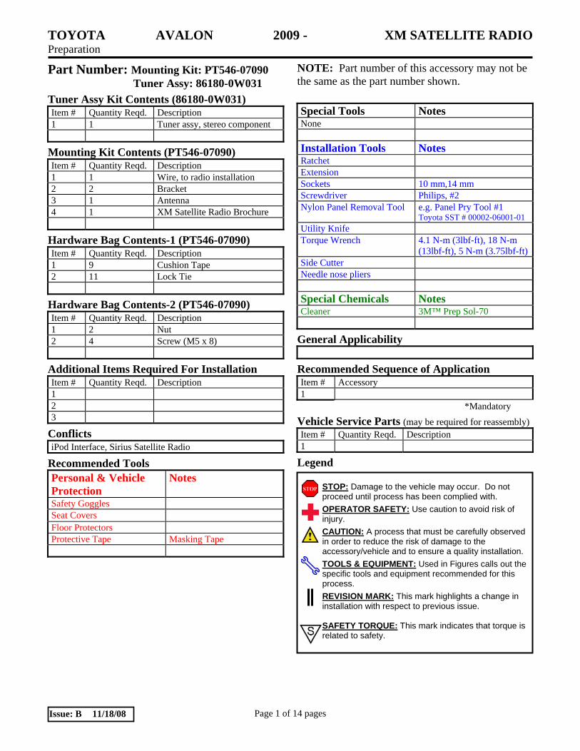
(c) Install the receiver on the right side of the luggage compartment using nuts. Orient the tuner so the receiver connectors are facing downward as shown. Torque the nuts to 5 N-m (45 lbf-in). (Fig. 3-3)
(d) Clean the cushion tape mounting area.
(e) If there is excessive slack, bundle the excess using another cushion tape. (Fig. 3-4)
(f) Determine the area where the receiver cable rubs the rear inner fender. Place cushion tape in that area. (Fig. 3-4)
(g) Secure the antenna cable connection to the receiver as shown. (Fig.3-4)
4. Reinstall the Radio/Player Head Unit.
(a) Connect the satellite tuner cable and connectors into the rear of the head unit.
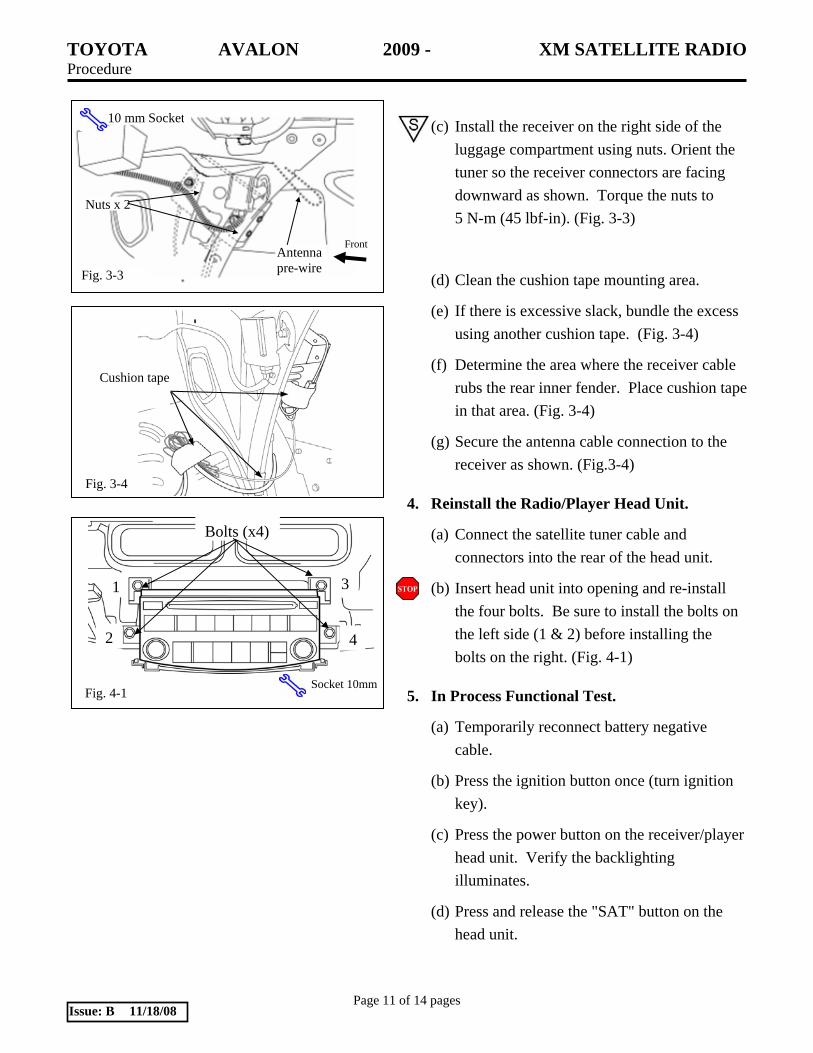
(b) Insert head unit into opening and re-install the four bolts. Be sure to install the bolts on the left side (1 & 2) before installing the bolts on the right. (Fig. 4-1)
5. In Process Functional Test.
(a) Temporarily reconnect battery negative cable.
(b) Press the ignition button once (turn ignition key).
(c) Press the power button on the receiver/player head unit. Verify the backlighting illuminates.
(d) Press and release the "SAT" button on the head unit.
Front
Nuts x 2
Fig. 3-3
10 mm Socket
Cushion tape
Fig. 3-4
Antenna pre-wire
Socket 10mm
Bolts (x4)
1
2
3
4
Fig. 4-1

TOYOTA AVALON 2009 - XM SATELLITE RADIO Procedure
Page 12 of 14 pages Issue: B 11/18/08
(1) Verify that a satellite channel is received, or a "NO SIGNAL" message appears on the display.
NOTE: If "ANTENNA" appears (flashing) on the display – then the antenna cable is disconnected from the satellite tuner.
NOTE: If the head unit will not tune or go into satellite mode – then the tuner cable is disconnected from the satellite tuner.
(e) Disconnect battery negative cable.
6. Complete the Reassembly of the Vehicle.
(a) Reinstall glove box.
(b) Reinstall console panel.
(1) Reconnect any disconnected connectors.
(c) Reinstall trim pieces around steering column.
(1) Reconnect any disconnected connectors.
(d) Reinstall cowl cover.
(e) Reinstall B-pillar column cover and weather strip.
(f) Reinstall front doorsill.
(g) Reinstall rear doorsill.
(h) Reinstall rear passenger seat.
NOTE: Torque the seat back bolt to 18 N-m. (13 lbf-ft)
(i) Reinstall trunk trim piece and trunk mat.
(j) Verify the panels fit together properly with no uneven gaps between them.

TOYOTA AVALON 2009 - XM SATELLITE RADIO Procedure
Page 13 of 14 pages Issue: B 11/18/08
7. Reconnect Battery Cable.
(a) Reconnect the vehicle’s negative battery cable. (Fig. 7-1)
(1) Position the negative terminal at the original factory position.
(2) Tighten the nut with 4.1 N-m (36 lbf-in) of torque.
(3) Be careful not to touch the positive battery terminal.
(b) Clean up and remove any trash.
(c) Place the owner "XM Satellite Radio" brochure in the glove box.
(d) Reset the power windows.
(1) Turn ignition key to ON position.
(2) Push down the power window switches of each door, and lower the windows halfway.
(3) Pull up the switches until the windows close and hold switches up for a further one (1) second (minimum.)
(e) Reset the power moon roof.
(1) Push and hold moon roof switch to close side until moon roof closes. Hold for a further 2 seconds.
Negative Battery Cable
Fig. 7-1
Torque Wrench, 10mm Socket

TOYOTA AVALON 2006 - XM SATELLITE RADIO Checklist - these points MUST be checked to ensure a quality installation.
Check: Look For:
Page 14 of 14 pages Issue: B 11/18/08
Accessory Function Checks
Satellite Radio Tuner.
Receiver/player Assembly.
Vehicle Function Checks
Hazard Switch.
Rear Seat Recliner
HVAC.
Rear Sun Screen
Trunk Lid Lock
IP Dimmer Control
Outside Mirrors
Ignition
Rear Passenger Seat.
Rear Passenger Seat Back.
SRS Warning Light.
Passenger's Seat Belt Reminder Light.
*Verify the proper operation of the Satellite Radio Tuner.
*Verify the proper operation of the Receiver/player Assembly
*(Refer to the receiver assembly and radio owner's manuals.)
Proper operation of the hazard switch.
Rear seat reclines and returns
Proper operation of the air conditioning
system.
Functioning rear sun screen
Functioning trunk lid lock
Functioning IP illuminator dimmer
Functioning outside mirrors
Functioning ignition
Removed seat is securely fastened.
Seat in upright position and seat back lock
mechanism secured.
SRS warning light illuminates for
approximately 6 seconds with the ignition
ON, and then goes out.
Proper operation of the passenger's seat belt
reminder light.