Embed Size (px)
Citation preview
TOYOTA COROLLA 2008 - INTERFACE KIT FOR IPOD Preparation
Page 1 of 17 pages DIOIssue B: 5/23/08
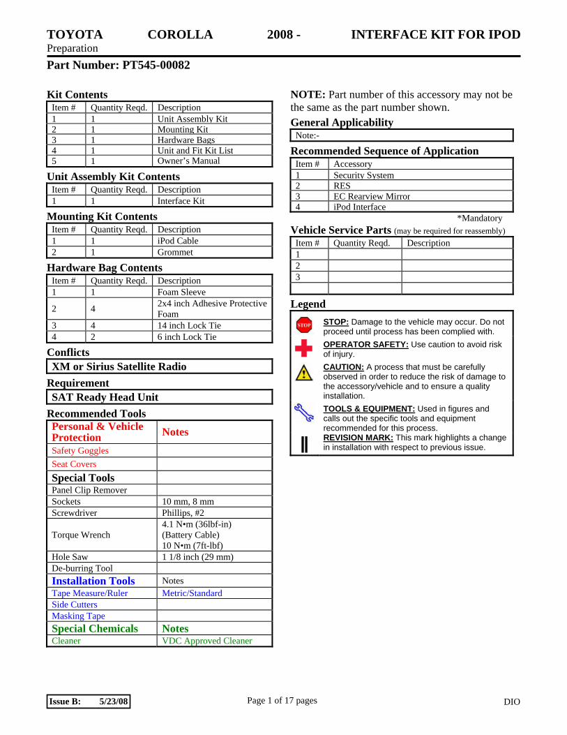
Part Number: PT545-00082
Kit Contents Item # Quantity Reqd. Description 1 1 Unit Assembly Kit 2 1 Mounting Kit 3 1 Hardware Bags 4 1 Unit and Fit Kit List5 1 Owner’s Manual
Unit Assembly Kit Contents Item # Quantity Reqd. Description 1 1 Interface Kit
Mounting Kit Contents Item # Quantity Reqd. Description 1 1 iPod Cable 2 1 Grommet
Hardware Bag Contents Item # Quantity Reqd. Description 1 1 Foam Sleeve
2 4 2x4 inch Adhesive Protective Foam
3 4 14 inch Lock Tie 4 2 6 inch Lock Tie
Conflicts XM or Sirius Satellite Radio
Requirement SAT Ready Head Unit
Recommended Tools Personal & Vehicle Protection Notes Safety Goggles Seat Covers Special Tools Panel Clip Remover Sockets 10 mm, 8 mm Screwdriver Phillips, #2
Torque Wrench 4.1 N•m (36lbf-in) (Battery Cable) 10 N•m (7ft-lbf)
Hole Saw 1 1/8 inch (29 mm) De-burring Tool Installation Tools Notes Tape Measure/Ruler Metric/Standard Side Cutters Masking Tape Special Chemicals Notes Cleaner VDC Approved Cleaner
NOTE: Part number of this accessory may not be the same as the part number shown. General Applicability
Note:-
Recommended Sequence of Application Item # Accessory 1 Security System2 RES3 EC Rearview Mirror 4 iPod Interface
*Mandatory Vehicle Service Parts (may be required for reassembly)
Item # Quantity Reqd. Description 1 2 3
Legend STOP: Damage to the vehicle may occur. Do not
proceed until process has been complied with. OPERATOR SAFETY: Use caution to avoid risk
of injury. CAUTION: A process that must be carefully
observed in order to reduce the risk of damage to the accessory/vehicle and to ensure a quality installation.
TOOLS & EQUIPMENT: Used in figures and calls out the specific tools and equipment recommended for this process.
REVISION MARK: This mark highlights a change in installation with respect to previous issue.
TOYOTA COROLLA 2008 - INTERFACE KIT FOR IPOD Preparation
Page 2 of 17 pages DIOIssue B: 5/23/08
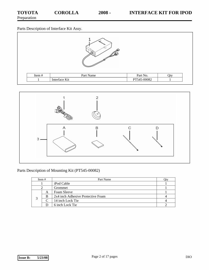
Parts Description of Interface Kit Assy.
Item # Part Name Part No. Qty 1 Interface Kit PT545-00082 1
Parts Description of Mounting Kit (PT545-00082)
Item # Part Name Qty 1 iPod Cable 1 2 Grommet 1
A Foam Sleeve 1 B 2x4 inch Adhesive Protective Foam 4 C 14 inch Lock Tie 4 3
D 6 inch Lock Tie 2
1
TOYOTA COROLLA 2008 - INTERFACE KIT FOR IPOD Procedure
Page 3 of 17 pages DIOIssue B: 5/23/08
Care must be taken when installing this accessory to ensure that damage does not occur to the vehicle. The installation of this accessory should follow approved guidelines to ensure a quality installation. These guidelines can be found in the Accessory Installation Practices document. The Accessory Installation Practices document covers such items as:
• Vehicle Protection (use of covers and blankets, cleaning chemicals, etc.). • Safety (eye protection, rechecking torque procedure, etc.). • Vehicle Disassembly/Reassembly (panel removal, part storage, etc.). • Electrical Component Disassembly/Reassembly (battery disconnection, connector removal, etc.).
Please see your Toyota dealer for a copy of the Accessory Installation Practices document.
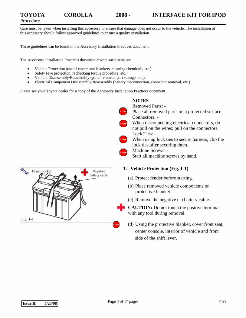
NOTES Removed Parts: - Place all removed parts on a protected surface. Connectors: - When disconnecting electrical connectors, do not pull on the wires; pull on the connectors. Lock Ties: - When using lock ties to secure harness, clip the lock ties after securing them. Machine Screws: - Start all machine screws by hand.
1. Vehicle Protection (Fig. 1-1)
(a) Protect fender before starting.
(b) Place removed vehicle components on protective blanket.
(c) Remove the negative (–) battery cable.
CAUTION: Do not touch the positive terminal with any tool during removal.
(d) Using the protective blanket, cover front seat, center console, interior of vehicle and front side of the shift lever.
STOP
STOP
STOP
STOP
TOYOTA COROLLA 2008 - INTERFACE KIT FOR IPOD Procedure
Page 4 of 17 pages DIOIssue B: 5/23/08
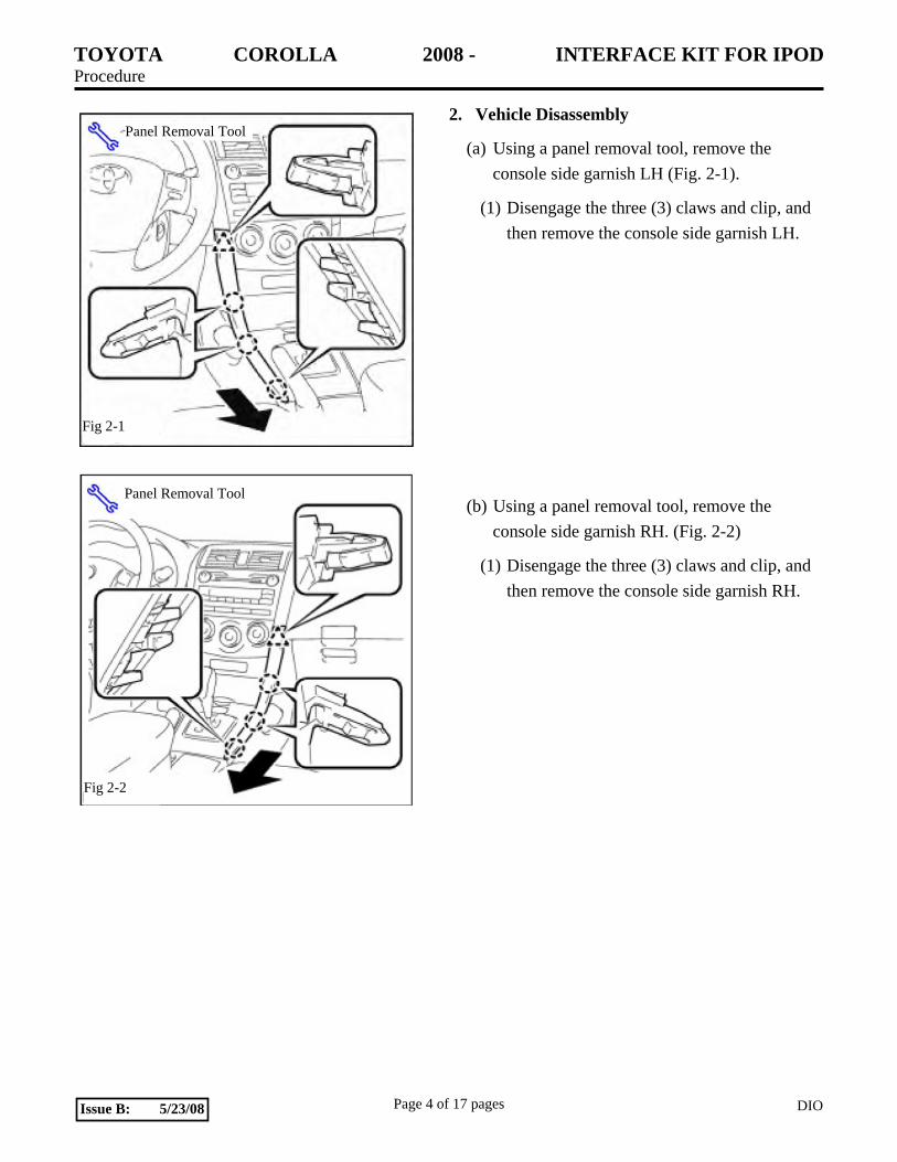
2. Vehicle Disassembly
(a) Using a panel removal tool, remove the console side garnish LH (Fig. 2-1).
(1) Disengage the three (3) claws and clip, and then remove the console side garnish LH.
(b) Using a panel removal tool, remove the console side garnish RH. (Fig. 2-2)
(1) Disengage the three (3) claws and clip, and then remove the console side garnish RH.
Fig 2-1
Panel Removal Tool
Fig 2-2
Panel Removal Tool
TOYOTA COROLLA 2008 - INTERFACE KIT FOR IPOD Procedure
Page 5 of 17 pages DIOIssue B: 5/23/08
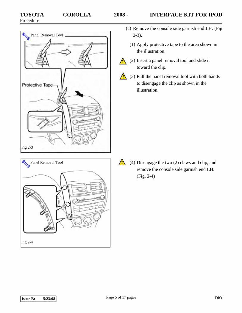
(c) Remove the console side garnish end LH. (Fig. 2-3).
(1) Apply protective tape to the area shown in the illustration.
(2) Insert a panel removal tool and slide it toward the clip.
(3) Pull the panel removal tool with both hands to disengage the clip as shown in the illustration.
(4) Disengage the two (2) claws and clip, and remove the console side garnish end LH. (Fig. 2-4)
Fig 2-3
Panel Removal Tool
Fig 2-4
Panel Removal Tool
TOYOTA COROLLA 2008 - INTERFACE KIT FOR IPOD Procedure
Page 6 of 17 pages DIOIssue B: 5/23/08
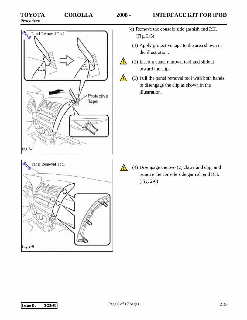
(d) Remove the console side garnish end RH. (Fig. 2-5)
(1) Apply protective tape to the area shown in the illustration.
(2) Insert a panel removal tool and slide it toward the clip.
(3) Pull the panel removal tool with both hands to disengage the clip as shown in the illustration.
(4) Disengage the two (2) claws and clip, and remove the console side garnish end RH. (Fig. 2-6)
Fig 2-5
Panel Removal Tool
Fig 2-6
Panel Removal Tool
TOYOTA COROLLA 2008 - INTERFACE KIT FOR IPOD Procedure
Page 7 of 17 pages DIOIssue B: 5/23/08
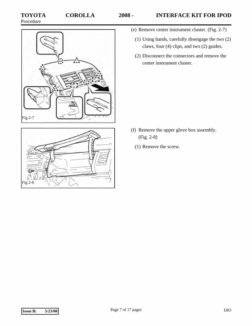
(e) Remove center instrument cluster. (Fig. 2-7)
(1) Using hands, carefully disengage the two (2) claws, four (4) clips, and two (2) guides.
(2) Disconnect the connectors and remove the center instrument cluster.
(f) Remove the upper glove box assembly. (Fig. 2-8)
(1) Remove the screw.
Fig 2-7
Fig 2-8
TOYOTA COROLLA 2008 - INTERFACE KIT FOR IPOD Procedure
Page 8 of 17 pages DIOIssue B: 5/23/08
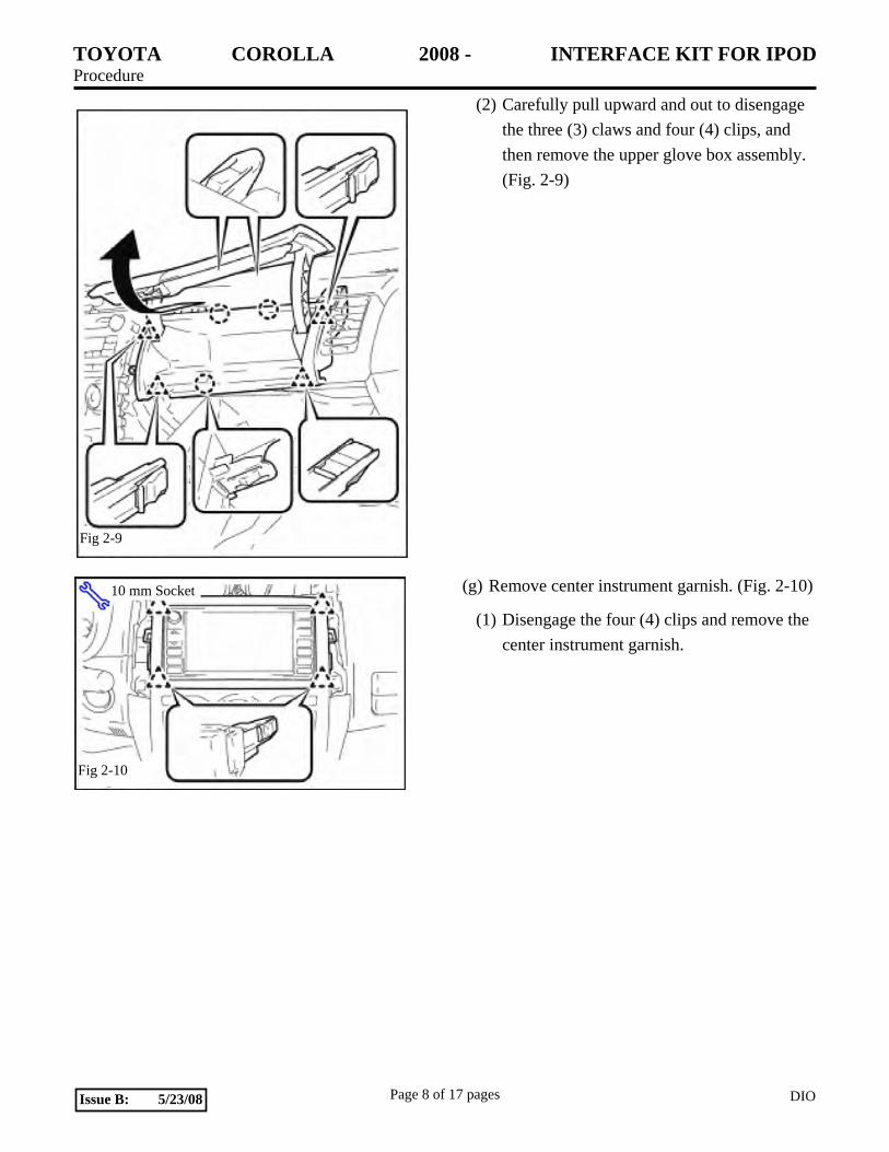
(2) Carefully pull upward and out to disengage the three (3) claws and four (4) clips, and then remove the upper glove box assembly. (Fig. 2-9)
(g) Remove center instrument garnish. (Fig. 2-10)
(1) Disengage the four (4) clips and remove the center instrument garnish.
Fig 2-9
Fig 2-10
10 mm Socket
TOYOTA COROLLA 2008 - INTERFACE KIT FOR IPOD Procedure
Page 9 of 17 pages DIOIssue B: 5/23/08
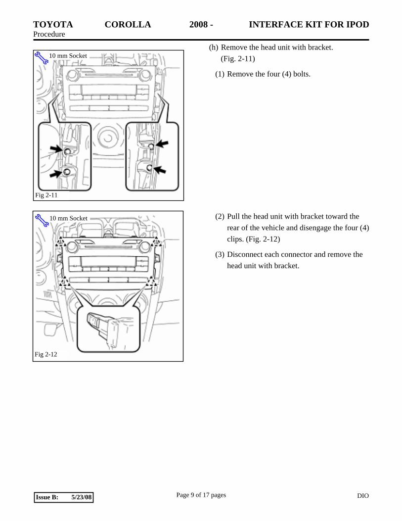
(h) Remove the head unit with bracket. (Fig. 2-11)
(1) Remove the four (4) bolts.
(2) Pull the head unit with bracket toward the rear of the vehicle and disengage the four (4) clips. (Fig. 2-12)
(3) Disconnect each connector and remove the head unit with bracket.
Fig 2-11
10 mm Socket
Fig 2-12
10 mm Socket
TOYOTA COROLLA 2008 - INTERFACE KIT FOR IPOD Procedure
Page 10 of 17 pages DIOIssue B: 5/23/08
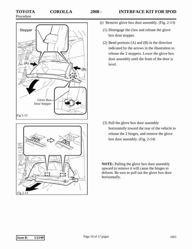
(i) Remove glove box door assembly. (Fig. 2-13)
(1) Disengage the claw and release the glove box door stopper.
(2) Bend portions (A) and (B) in the direction indicated by the arrows in the illustration to release the 2 stoppers. Lower the glove box door assembly until the front of the door is level.
(3) Pull the glove box door assembly horizontally toward the rear of the vehicle to release the 2 hinges, and remove the glove box door assembly. (Fig. 2-14)
NOTE: Pulling the glove box door assembly upward to remove it will cause the hinges to deform. Be sure to pull out the glove box door horizontally.
Fig 2-13
Glove Box Door Stopper
Fig 2-14
TOYOTA COROLLA 2008 - INTERFACE KIT FOR IPOD Procedure
Page 11 of 17 pages DIOIssue B: 5/23/08
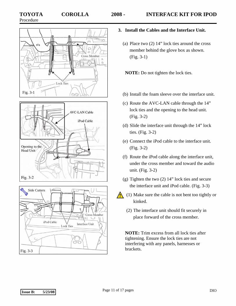
3. Install the Cables and the Interface Unit.
(a) Place two (2) 14” lock ties around the cross
member behind the glove box as shown. (Fig. 3-1)
NOTE: Do not tighten the lock ties.
(b) Install the foam sleeve over the interface unit.
(c) Route the AVC-LAN cable through the 14” lock ties and the opening to the head unit. (Fig. 3-2)
(d) Slide the interface unit through the 14” lock ties. (Fig. 3-2)
(e) Connect the iPod cable to the interface unit. (Fig. 3-2)
(f) Route the iPod cable along the interface unit, under the cross member and toward the audio unit. (Fig. 3-2)
(g) Tighten the two (2) 14” lock ties and secure the interface unit and iPod cable. (Fig. 3-3)
(1) Make sure the cable is not bent too tightly or kinked.
(2) The interface unit should fit securely in place forward of the cross member.
NOTE: Trim excess from all lock ties after tightening. Ensure the lock ties are not interfering with any panels, harnesses or brackets.
Fig. 3-1
Fig. 3-3
Side Cutters
TOYOTA COROLLA 2008 - INTERFACE KIT FOR IPOD Procedure
Page 12 of 17 pages DIOIssue B: 5/23/08
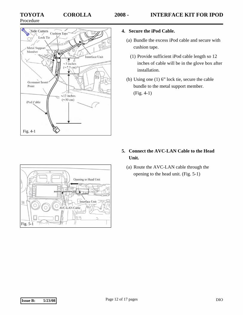
4. Secure the iPod Cable.
(a) Bundle the excess iPod cable and secure with cushion tape.
(1) Provide sufficient iPod cable length so 12 inches of cable will be in the glove box after installation.
(b) Using one (1) 6” lock tie, secure the cable bundle to the metal support member. (Fig. 4-1)
5. Connect the AVC-LAN Cable to the Head Unit.
(a) Route the AVC-LAN cable through the opening to the head unit. (Fig. 5-1)
Fig. 5-1
Fig. 4-1
Side Cutters
TOYOTA COROLLA 2008 - INTERFACE KIT FOR IPOD Procedure
Page 13 of 17 pages DIOIssue B: 5/23/08
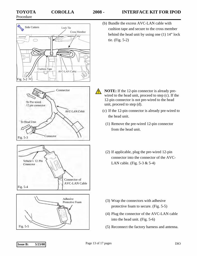
(b) Bundle the excess AVC-LAN cable with cushion tape and secure to the cross member behind the head unit by using one (1) 14” lock tie. (Fig. 5-2)
NOTE: If the 12-pin connector is already pre-wired to the head unit, proceed to step (c). If the 12-pin connector is not pre-wired to the head unit, proceed to step (d).
(c) If the 12-pin connector is already pre-wired to the head unit.
(1) Remove the pre-wired 12-pin connector from the head unit.
(2) If applicable, plug the pre-wired 12-pin connector into the connector of the AVC-LAN cable. (Fig. 5-3 & 5-4)
(3) Wrap the connectors with adhesive protective foam to secure. (Fig. 5-5)
(4) Plug the connector of the AVC-LAN cable into the head unit. (Fig. 5-6)
(5) Reconnect the factory harness and antenna.
Fig. 5-5
Connector
Fig. 5-3
Fig. 5-4
Connector of AVC-LAN Cable
Fig. 5-2
Side Cutters
TOYOTA COROLLA 2008 - INTERFACE KIT FOR IPOD Procedure
Page 14 of 17 pages DIOIssue B: 5/23/08
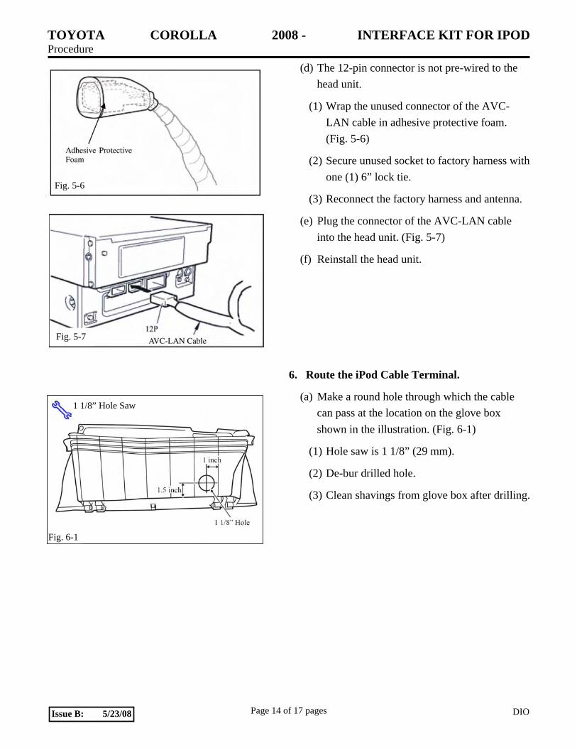
(d) The 12-pin connector is not pre-wired to the head unit.
(1) Wrap the unused connector of the AVC-LAN cable in adhesive protective foam. (Fig. 5-6)
(2) Secure unused socket to factory harness with one (1) 6” lock tie.
(3) Reconnect the factory harness and antenna.
(e) Plug the connector of the AVC-LAN cable into the head unit. (Fig. 5-7)
(f) Reinstall the head unit.
6. Route the iPod Cable Terminal.
(a) Make a round hole through which the cable can pass at the location on the glove box shown in the illustration. (Fig. 6-1)
(1) Hole saw is 1 1/8” (29 mm).
(2) De-bur drilled hole.
(3) Clean shavings from glove box after drilling.
Fig. 5-6
Fig. 5-7
1 1/8” Hole Saw
Fig. 6-1
TOYOTA COROLLA 2008 - INTERFACE KIT FOR IPOD Procedure
Page 15 of 17 pages DIOIssue B: 5/23/08
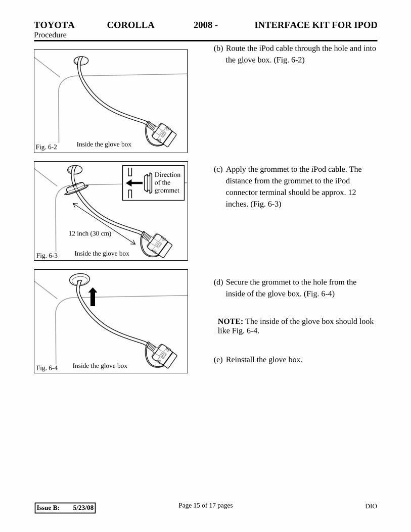
(b) Route the iPod cable through the hole and into the glove box. (Fig. 6-2)
(c) Apply the grommet to the iPod cable. The distance from the grommet to the iPod connector terminal should be approx. 12 inches. (Fig. 6-3)
(d) Secure the grommet to the hole from the inside of the glove box. (Fig. 6-4)
NOTE: The inside of the glove box should look like Fig. 6-4.
(e) Reinstall the glove box.
Fig. 6-2 Inside the glove box
Fig. 6-3 Inside the glove box
12 inch (30 cm)
Fig. 6-4 Inside the glove box
TOYOTA COROLLA 2008 - INTERFACE KIT FOR IPOD Procedure
Page 16 of 17 pages DIOIssue B: 5/23/08
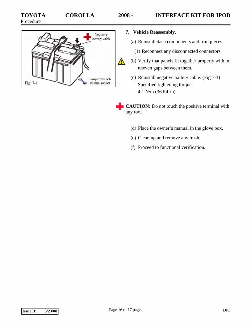
7. Vehicle Reassembly.
(a) Reinstall dash components and trim pieces.
(1) Reconnect any disconnected connectors.
(b) Verify that panels fit together properly with no uneven gaps between them.
(c) Reinstall negative battery cable. (Fig 7-1) Specified tightening torque: 4.1 N·m (36 lbf-in)
CAUTION: Do not touch the positive terminal with any tool.
(d) Place the owner’s manual in the glove box.
(e) Clean up and remove any trash.
(f) Proceed to functional verification.
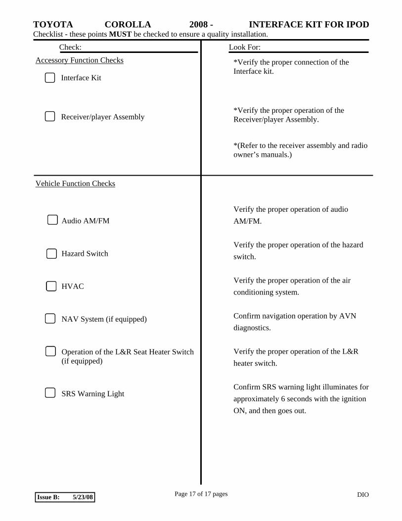
TOYOTA COROLLA 2008 - INTERFACE KIT FOR IPOD Checklist - these points MUST be checked to ensure a quality installation.
Check: Look For:
Page 17 of 17 pages DIOIssue B: 5/23/08
Accessory Function Checks
Interface Kit
Receiver/player Assembly
Vehicle Function Checks
Audio AM/FM
Hazard Switch
HVAC
NAV System (if equipped)
Operation of the L&R Seat Heater Switch (if equipped)
SRS Warning Light
*Verify the proper connection of the Interface kit.
*Verify the proper operation of the Receiver/player Assembly.
*(Refer to the receiver assembly and radio owner’s manuals.)
Verify the proper operation of audio AM/FM.
Verify the proper operation of the hazard switch.
Verify the proper operation of the air conditioning system.
Confirm navigation operation by AVN diagnostics.
Verify the proper operation of the L&R heater switch.
Confirm SRS warning light illuminates for approximately 6 seconds with the ignition ON, and then goes out.


![ISSB Water Tank Consruction Manual 120908 FINAL[1]](https://img.pdfslide.us/doc/110x75/543d24b8afaf9fa00a8b4569/issb-water-tank-consruction-manual-120908-final1.jpg)