Embed Size (px)
Citation preview

TOYOTA SIENNA 2011 - XM SATELLITE RADIO Preparation
Page 1 of 16 pages Issue: B 02/01/10
Part Number: Mounting Kit PT546-08100 Tuner Assy 86180-0W032
NOTE: Part number of this accessory may not be the same as the part number shown.
Tuner Assembly Kit Contents (86180-0W032) Item # Quantity Reqd. Description
1 1 Tuner Assy, Stereo Component
Mounting Kit Contents (PT546-08100) Item # Quantity Reqd. Description
1 1 Wire, To Radio Installation 2 1 Cord ( Antenna Extension ) 3 1 Ground Cable 4 2 Tuner Bracket 5 2 Base Bracket 6 1 Template
(to locate base bracket) 7 4 Cushion ( Butyl ) 8 3 Hardware Bags 9 1 XM Satellite Radio Brochure
Hardware Bag Contents – 1 (PT546-08100) Item # Quantity Reqd. Description
1 4 Bolt ( M5 L8 ) 2 4 Nut ( M6 )
Hardware Bag Contents – 2 (PT546-08100) Item # Quantity Reqd. Description
1 3 Cushion Tape 2 10 Lock Tie
Hardware Bag Contents – 3 (PT546-08100) Item # Quantity Reqd. Description
1 5 Seal ( Sheet Tape) 2 13 Lock Tie
Additional Items Required For Installation Item # Quantity Reqd. Description
Conflicts Ipod
Requirements XM satellite ready base grade audio
Vehicle Service Parts (may be required for reassembly) Item # Quantity Reqd. Description
Recommended Tools Personal & Vehicle Protection
Notes
Safety Goggles Seat Covers Floor Protectors
Special Tools Notes Arch (Carpet) Punch 5/16” Hole Diameter Seat Brace Tool Installation Tools Notes Ratchet Extensions Sockets 10 mm, 12 mm, 14 mm Torque Wrench 4.1 N•m (36 lbf•in): Battery Cable,
37 N•m (27 lbf•ft): Front Seat 42 N•m (31 lbf•ft): Seat Belt
Screwdriver Phillips, #2 Panel Removal Tool e.g. Panel Pry Tool #1
Toyota SST # 00002-06001-01 Masking Tape (2” wide) Mallet Electrical Tape Side Cutter Special Chemicals Notes Cleaner VDC approved cleaner.
General Applicability
Recommended Sequence of Application Item # Accessory
1 V4 RES w/o Smart 2 Blue Logic
3 XM *Mandatory
Legend
STOP: Damage to the vehicle may occur. Do not proceed until process has been complied with.
OPERATOR SAFETY: Use caution to avoid risk of injury.
CAUTION: A process that must be carefully observed in order to reduce the risk of damage to the accessory/vehicle and to ensure a quality installation.
TOOLS & EQUIPMENT: Used in Figures calls out the specific tools and equipment recommended for this process.
REVISION MARK: This mark highlights a change in installation with respect to previous issue.
SAFETY TORQUE: This mark indicates that torque is related to safety.
TOYOTA SIENNA 2011- XM SATELLITE RADIO Preparation
Page 2 of 16 pages Issue: B 02/01/10
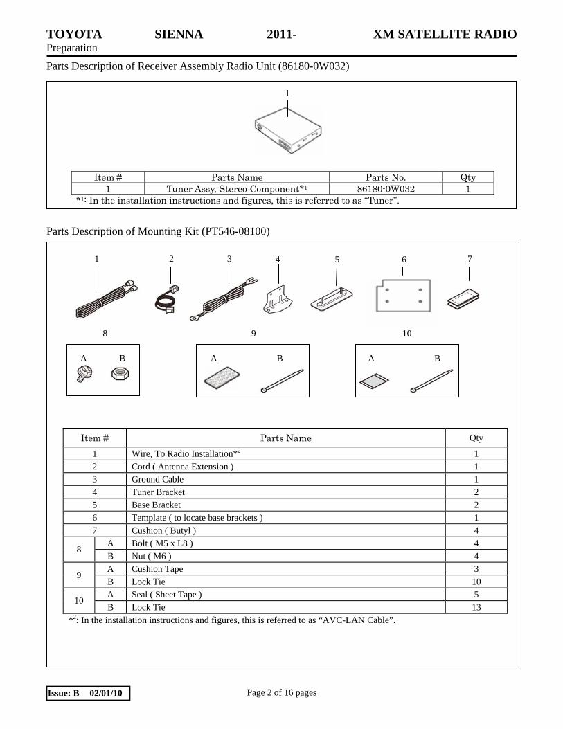
Parts Description of Receiver Assembly Radio Unit (86180-0W032) Parts Description of Mounting Kit (PT546-08100)
Item # Parts Name Qty
1 Wire, To Radio Installation*2 1
2 Cord ( Antenna Extension ) 1 3 Ground Cable 1
4 Tuner Bracket 2
5 Base Bracket 2 6 Template ( to locate base brackets ) 1
7 Cushion ( Butyl ) 4
A Bolt ( M5 x L8 ) 4 8
B Nut ( M6 ) 4
A Cushion Tape 3 9
B Lock Tie 10 A Seal ( Sheet Tape ) 5
10 B Lock Tie 13
*2: In the installation instructions and figures, this is referred to as “AVC-LAN Cable”.
Item # Parts Name Parts No. Qty 1 Tuner Assy, Stereo Component*1 86180-0W032 1
*1: In the installation instructions and figures, this is referred to as “Tuner”.
1
32 1 4 5 6 7
A B A A
8 9 10
B B

TOYOTA SIENNA 2011 - XM SATELLITE RADIO Procedure
Page 3 of 16 pages Issue: B 02/01/10
Care must be taken when installing this accessory to ensure damage does not occur to the vehicle. The installation of this accessory should follow approved guidelines to ensure a quality installation. These guidelines can be found in the "Accessory Installation Practices" document. This document covers such items as:-
Vehicle Protection (use of covers and blankets, cleaning chemicals, etc.). Safety (eye protection, rechecking torque procedure, etc.). Vehicle Disassembly/Reassembly (panel removal, part storage, etc.). Electrical Component Disassembly/Reassembly (battery disconnection, connector removal, etc.).
Please see your Toyota dealer for a copy of this document.
NOTES
Removed Parts: - Place all removed parts on a protected surface.
Connectors: - When disconnecting connectors, do not pull on the wires; pull on the connectors.
Lock Ties: - When using lock ties to secure harness, clip the lock ties after securing them.
Machine Screws: - Start all machine screws by hand.
When disconnecting a yellow connector for
the SRS airbag, wait 90 seconds or more after
disconnecting the negative battery cable before
performing the next task.
1. Disassembly of Vehicle
(a) Tape fuel door closed to prevent door from
opening during lower IP removal process.
(b) Open tail gate, and side doors.
(c) Remove the negative battery cable. (Fig. 1-1)
Fig. 1-1
Negative Battery cable
10 mm Socket

TOYOTA SIENNA 2011 - XM SATELLITE RADIO Procedure
Page 4 of 16 pages Issue: B 02/01/10
Fig. 1-4
Clip x 6
Belt buckle
(d) Remove the rear threshold trim plate.
(Fig. 1-2)
(1) Remove 3 bolts and cargo tie down
hardware.
(2) Disengage 6 clips and remove panel.
(e) Fold the drivers’ side rear seat into the
storage area using the handle and strap.
(Fig. 1-3)
(f) Remove the upper tail gate trim. (Fig. 1-4)
(1) Disengage 6 clips, and rotate belt buckle
so that it can pass through the panel
opening.
(g) Remove seat belt and luggage hook.
(Fig. 1-5)
(1) Press center pin of hook to disengage.
(2) Cover seat belt mounting brackets with
protective cover to prevent scratching.
Nylon pry tool
Fig. 1-5
Seat belt anchor
Hook
14 mm socket
Fig. 1-3
Fig. 1-2
Clip x 6
Nylon pry tool 10mm socket
Bolts x 3
Clip release point Clip release point

TOYOTA SIENNA 2011 - XM SATELLITE RADIO Procedure
Page 5 of 16 pages Issue: B 02/01/10
Clip x 4
Fig. 1-6
(h) Remove driver side, middle door scuff plate.
(Fig. 1-6)
(1) Disengage the 4 clips on the scuff plate.
(i) Remove large rear driver side trim piece.
(Fig. 1-7)
(1) Remove circular sensor and unplug wire
harness if applicable.
(2) Disengage clips and claws to remove
panel.
Panels 1 & 2 are fused together do not
attempt to separate them. Panel 3 can be
separated from the other panels.
(3) Pull back panel, pass seat belt through
openings, and disconnect any wiring
before removing panel.
(j) Remove the front scuff plate. (Fig. 1-8)
(1) Disengage the 4 clips to remove the front
driver side scuff plate. Follow the
revised front scuff plate removal process
(V2, V4, V5).
1
2
3
Fig. 1-7
Clip x 11 Claw x 9
Sensor
Nylon pry tool
Nylon pry tool
Fig. 1-8
Clip x 4 Nylon pry tool

TOYOTA SIENNA 2011 - XM SATELLITE RADIO Procedure
Page 6 of 16 pages Issue: B 02/01/10
(k) Remove the driver side cowl trim board.
(Fig. 1-9)
(1) Remove the plastic nut.
(l) Remove driver side lower dash panel.
(Fig. 1-10)
(1) Remove the 2 10mm bolts on the bottom
corners of the panel.
(2) Disengage the 10 clips to remove the
lower dash piece.
(3) Disconnect any electrical wire harnesses.
(4) Disconnect the fuel cap and hood release
latches.
Fig. 1-10
Hood & Gas latches
Nylon pry tool 10mm Socket
Clip x 10
Bolt x 2
Electrical connections
Fig. 1-9
Nylon pry tool
Plastic Nut
Clip x 2
Cowl Side Trim Board

TOYOTA SIENNA 2011 - XM SATELLITE RADIO Procedure
Page 7 of 16 pages Issue: B 02/01/10
(m) Remove the passenger side dash trim.
(1) Disengage the 8 clips and disconnect any
electrical connections to remove the
wood grain dash piece. (Fig. 1-11)
(2) Remove shift lever panel. (Fig 1-12)
(1) Unscrew knob.
(2) Disengage 4 clips.
(3) Disconnect wire harness, and remove
panel.
(4) Move shift lever to L.
(3) Remove HVAC control panel. (Fig 1-13)
(1) Disengage 6 clips, disconnect any
wire harness connections, and remove
control panel.
(4) Apply protective tape to dash overhang at
left upper corner of radio head unit.
(Fig. 1-14)
Fig. 1-11
Nylon pry tool Clip x 8
Clip x 4
Fig. 1-12
Nylon pry tool
Clip x 6
Fig. 1-13
Nylon pry tool
Fig. 1-14
Protective Tape

TOYOTA SIENNA 2011 - XM SATELLITE RADIO Procedure
Page 8 of 16 pages Issue: B 02/01/10
(n) Remove radio assembly. (Fig. 1-15)
(1) Remove the bolts located below the L &
R sides of the radio.
(2) Disengage the 5 clips and 2 claws.
(3) Pull out the radio / vent assy.
(4) Disconnect radio harness connections.
(5) Vent covers will remain on radio.
2. Antenna Extension Installation
(a) Connect extension cable. (Fig 2-1)
(1) Locate antenna connection above head
liner in tail gate area.
(2) Remove antenna clip from roof hole,
disconnect antenna, disconnect holder
from clip and discard empty connector.
(3) Clip new extension cable holder onto the
antenna clip.
(4) Connect the vehicle antenna, and return
the clip to the roof panel hole.
(b) Route extension cable to the left and secure
to top of the head liner with 5 sheet tapes
where indicated. (Fig. 2-2)
Fig. 2-2
Sheet tape x 5 Extension cable connector
Fig. 1-15
Nylon pry tool 10mm socket
Clip x 5 Claw x 2
Bolt x 4 (2 on each side)
Antenna clip
Nylon pry tool, electrical tape,
Fig 2-1
Extension cable

TOYOTA SIENNA 2011 - XM SATELLITE RADIO Procedure
Page 9 of 16 pages Issue: B 02/01/10
(c) Route antenna extension cable along
corrugated wire harness, and secure with 4
lock ties. (Fig. 2-3)
Route extension cable behind any brackets or
mechanism located in this area.
(d) Secure extension cable to existing vehicle
harness with an additional 5 lock ties as
shown. (Fig. 2-4)
(e) Route extension cable along vehicle harness,
and secure with 3 lock ties. (Fig. 2-5)
(1) Route cable under black bracket, and
between the black and white wire tubes.
(2) Pass extension cable through white clips
to follow existing harness.
Fig. 2-3 Lock tie x 4
Fig. 2-4 Lock tie x 5
Lock tie installed during previous step
Fig. 2-5
Under black bracket, & between 2 wire tubes
Lock tie x 3

TOYOTA SIENNA 2011 - XM SATELLITE RADIO Procedure
Page 10 of 16 pages Issue: B 02/01/10
(f) Route the antenna extension cable under the
B pillar trim using a feeder tool, and secure
with 1 lock tie. (Fig. 2-6)
3. AVC-LAN Harness Installation
(a) Wrap the socket portion of the AVC-LAN
cable with cushion tape to secure the socket
to the main part of the harness.
(b) Secure the new harness to existing radio
wiring with 2 lock ties. Use vehicle wiring to
estimate length and route wire towards driver
side lower dash area. (Fig. 3-1)
(c) Route AVC-LAN cable along top side of
knee bolster air bag, towards cowl panel, and
secure with 2 lock ties & 2 cushion tapes.
Cushion tape should not be visible when the
vehicle is assembled. (Fig. 3-2)
(1) Apply cushion tape to top side of air bag
module to secure cable.
Fig. 2-6 Lock tie x 1
Fig. 3-1
Lock tie x 2 Cushion tape x 1
Plug Socket
Fig. 3-2
Cushion tape x 2 (Top side of air bag module)
Lock tie x 2

TOYOTA SIENNA 2011 - XM SATELLITE RADIO Procedure
Page 11 of 16 pages Issue: B 02/01/10
(d) Install ground wire hook behind existing bolt
in cowl area.
(e) Secure both AVC-LAN cable and ground
wire with an additional 2 lock ties. (Fig. 3-3)
(f) Route AVC-LAN cable and ground wire
along driver door, and secure both with 2
lock ties. (Fig. 3-4)
(1) Include the antenna extension cable in the
second lock tie.
(g) Remove the three (3) white plastic carpet
clips to allow wire harnesses to pass
underneath the carpet. (Fig. 3-5)
AVC-LAN cable
GND wire
Fig. 3-3 Lock tie x 2
Lock tie installed in previous step
10 mm socket
Lock tie x 2 Ant Cable
Lock tie installed in previous step
Fig. 3-4
White plastic carpet clips Fig. 3-5

TOYOTA SIENNA 2011 - XM SATELLITE RADIO Procedure
Page 12 of 16 pages Issue: B 02/01/10
Fig. 4-2
(h) Lean back driver seat. (Fig. 3-6)
(1) Open plastic access panels to expose 2
forward seat bolts, and remove bolts.
(2) Repeat process for 2 bolts on the back
side of the driver seat.
(3) Insert seat brace tool, and lean seat back
slightly.
(4) Disconnect white wire harness clip, lean
seat back, and rest on the center seat.
4. Tuner Install
(a) Align template cutout with carpet cutout to
position template under driver seat. (Fig. 4-1)
(b) Transfer the 4 hole locations to the carpet,
remove the template, and then use a carpet
punch to create 4 holes.
Always dry fit before installing or cutting.
(c) Install 8 butyl cushions to the base brackets
as shown. (Fig. 4-2)
Template
Alignment feature Fig. 4-1
Fig. 3-6 14mm socket
Seat bolts x 2
Base Brackets
Front
InboardCushion x 2
Cushion x 6 (Triple Stack)
4mm
5mm
A
B

TOYOTA SIENNA 2011 - XM SATELLITE RADIO Procedure
Page 13 of 16 pages Issue: B 02/01/10
(d) Lift carpet, and pass secure antenna
extension, AVC-LAN, ground cables through
the carpet cutout. The AVC-LAN, ground
cable, and antenna extension cable should be
routed under the “E-Brake” cable and fuel
door release cable.
(e) Lock tie the AVC-LAN, ground cable, and
antenna extension together with a lock tie.
(Fig. 4-3)
(f) Insert base brackets through cut holes,
remove the release paper, and press the
carpet down to install the base brackets.
(g) Lift the carpet, and verify the brackets are
properly mounted.
(h) Install tuner brackets and attach ground wire
to tuner. (Fig. 4-4)
(i) Install tuner assembly over base brackets,
and secure with supplied nuts.
(j) Plug in AVC-LAN & Antenna extension
cables; then bundle excess, secure with a
lock tie, and tuck under carpet through carpet
cutout. Insure XM harness is inboard of
vehicle seat harness. (Fig. 4-5)
L-bracket x 2
Bolt x 4
Ground wire
Screwdriver
Fig. 4-4
Tuner
Front
Fig. 4-3
Base bracket x 2
Lock tie
A B

TOYOTA SIENNA 2011 - XM SATELLITE RADIO Procedure
Page 14 of 16 pages Issue: B 02/01/10
5. In Process Functional Test.
(a) Temporarily reconnect negative battery
cable.
(b) Press the engine switch to "ACC" position.
(c) Press the power button on the receiver/player
head unit.
(d) Press and release the "SAT" button on the
head unit.
(1) Verify that a satellite channel is received,
or a "NO SIGNAL" message appears on
the display.
NOTE: If "ANTENNA" appears (flashing) on the display - then the antenna cable is disconnected from the satellite tuner.
NOTE: If the head unit will not tune or go into satellite mode - then the tuner cable is disconnected from the satellite tuner.
(e) Disconnect negative battery cable.
TOYOTA SIENNA 2011 - XM SATELLITE RADIO Procedure
Page 15 of 16 pages Issue: B 02/01/10
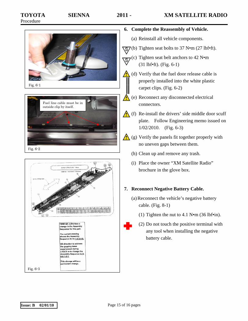
6. Complete the Reassembly of Vehicle.
(a) Reinstall all vehicle components.
(b) Tighten seat bolts to 37 N•m (27 lbf•ft).
(c) Tighten seat belt anchors to 42 N•m
(31 lbf•ft). (Fig. 6-1)
(d) Verify that the fuel door release cable is
properly installed into the white plastic
carpet clips. (Fig. 6-2)
(e) Reconnect any disconnected electrical
connectors.
(f) Re-install the drivers’ side middle door scuff
plate. Follow Engineering memo issued on
1/02/2010. (Fig. 6-3)
(g) Verify the panels fit together properly with
no uneven gaps between them.
(h) Clean up and remove any trash.
(i) Place the owner “XM Satellite Radio”
brochure in the glove box.
7. Reconnect Negative Battery Cable.
(a) Reconnect the vehicle’s negative battery
cable. (Fig. 8-1)
(1) Tighten the nut to 4.1 N•m (36 lbf•in).
(2) Do not touch the positive terminal with
any tool when installing the negative
battery cable.
Fig. 6-3
Fig. 6-1
Fuel line cable must be in outside clip by itself.
Fig. 6-2

TOYOTA SIENNA 2010 - XM SATELLITE RADIO Checklist - these points MUST be checked to ensure a quality installation.
Check: Look For:
Page 16 of 16 pages Issue: B 02/01/10
Accessory Function Checks
Satellite Radio Tuner
Receiver/player Assembly
Vehicle Function Checks
Driver’s seat belt reminder light
Removed seat
Proper operations of the removed seat lock
mechanism
SRS warning light
Lower dash functions
Hood release and fuel door levers
HVAC
Shifter light
Dash controls
Verify the proper operation of the satellite radio
tuner.
Verify the proper operation of the
receiver/player assembly.
(Refer to the receiver assy and radio owner's manuals.)
Verify the proper operation of the driver’s seat
belt reminder light.
Verify the removed seat is securely fastened.
Verify the proper operation of the removed seat
lock mechanism.
Verify the proper operation of the SRS warning
light.
Verify the proper operation of all lower dash
panel switches and controls.
Verify the proper operation of the hood release
& fuel door levers.
Verify the proper operation of HVAC controls.
Verify the proper function of the light on shifter panel.
Verify the proper operation of any other disconnected dash controls.