Embed Size (px)
Citation preview

Multi-Robot Cooperative Sensing and Localization 207
Multi-Robot Cooperative Sensing and Localization
Kai-Tai Song, Chi-Yi Tsai and Cheng-Hsien Chiu Huang
X
Multi-Robot Cooperative Sensing and Localization
Kai-Tai Song, Chi-Yi Tsai and Cheng-Hsien Chiu Huang
Institute of Electrical and Control Engineering, National Chiao Tung University 1001 Ta Hsueh Road, Hsinchu, Taiwan 300, ROC
E-mail: [email protected]; [email protected]; [email protected]
Abstract This chapter describes a method for mobile robot localization design based on multi-robot cooperative sensing. A multi-robot cooperative localization system is presented. The system utilizes visual detection and sensor data fusion techniques to achieve mobile robot localization. The visual detection system employs a stereo vision module for both observing other robots and obtaining environmental information. Each mobile robot is able to recognize its teammates by using onboard vision system. The localization error is reduced through the proposed sensor fusion algorithm. The cooperative localization algorithm consists of two stages: serial fusion and parallel fusion. Serial fusion aims to identify the positional uncertainty of an observed robot while parallel fusion reduces its positional error based on Kalman filtering. The multi-robot cooperative localization system has been realized through the client-server architecture. Experimental results are presented to validate the effectiveness of the proposed algorithms. Keywords: multi-robot system, mobile robot localization, cooperative localization, sensor data fusion, Kalman filtering.
1. Introduction
In recent years, multi-robot systems and distributed autonomous robotic systems have become important research areas in autonomous robotics (Parker, 1998), (Weigel et al., 2002). There are increasing interests in cooperative localization and map-building using a robot team. Traditionally, robot localization and map-building are resolved by a single robot equipped with various perception sensors (Gamini Dissanayake et al., 2001), (Nieto et al., 2002), (Nieto et al., 2003). However, a single mobile robot equipped with several types of sensors will consume much power and is more expensive to construct. A multi-robot system can overcome these drawbacks through cooperative sensing from simpler sensors and map-building will become more efficient by fusing results from each mobile robot. Many efforts have been put to cooperative localization of mobile robots. Several researchers utilize multi-robot cooperative sensing techniques to achieve cooperative localization (Fox et
10
www.intechopen.com

Robot Localization and Map Building208
al., 1998), (Zhang et al., 2000). A Monte Carlo Localization (MCL) algorithm was developed to localize two robots equipped with laser range finders (Thrun et al., 2001). The presented method gathers environmental data fast and can localize individual robot using a laser scanner. A cooperative localization and mapping method was proposed for two robots to localize themselves and for map-building (Rekleitis et al. 2003). The key idea is that one robot carries a target to act as a landmark, and the other equipped with a laser range finder and a camera observes the former for position correction. A Kalman filter based approach was presented to simultaneous localization of a group of robots by sensing the team members and combining position information from all teammates (Roumeliotis & Bekey, 2002). The hypothesis of this method is that the robots can communicate with their teammates and measure their respective poses. A collaborative landmark localization method was presented for multiple robots equipped with vision systems to localize themselves by estimating fixed landmarks (Stroupe & Balch, 2002). The fixed landmarks are established beforehand and the robot needs to record the landmark positions. However, when the number of robots increases to more than two, information from laser scanner will not be able to distinguish each robot. Vision-based systems have been widely exploited as a robotic perception sensor. They are also useful for distinguishing individual robot and handling the case of more than two robots. A vision-based cooperative mapping and localization method employed stereo vision to build a grid map and localize robots by features in grid map such as corners (Jennings et al., 1999). The key idea is to find corners in a grid map and compare these corners with a-priori landmarks at known positions. Hence, an accurate reference map of the environment is required in the method. A multi-robot MCL approach was presented to achieve the localization of a robot team with improved accuracy (Fox et al., 1999). The results show that the robots can localize themselves faster and with higher accuracy. However, although the MCL algorithm can be used for cooperative localization, it requires transmission of relatively large amount of information. On the other hand, a Kalman filtering approach can reduce not only the transmission of information but also the complexity of computing positional uncertainty. But a drawback of this approach is that the accuracy of the localization results will be decreased compared with the MCL methods. A distributed sensing method was developed based on Kalman filtering to improve the target localization (Stroupe & Martin, 2001). However, this method was only developed for recognizing and localizing a specific target. In a multi-robot cooperation system, it is desirable for each robot to recognize all of its teammates in cooperative localization. An effective algorithm is needed to fuse the observed information and reduce the sensing uncertainty. Furtherore, when a robot team consists of more than two teammates, the problem of communication, cooperation and recognition among teammates will become increasingly important. In this chapter, we developed a multi-robot cooperative localization scheme exploiting a stereo vision system. This scheme does not restrict the number of robot in a robot team and can collect all observational information of the environment form each robot. We establish a client-server architecture using wireless LAN to integrate the local sensory data from each robot (a client) to a server. The server stores the current position of each robot in order to reduce the transmission of information between robot teammates. The proposed multi-robot cooperative localization algorithm aims to estimate the optimal position and reduce the positional uncertainty of the observed robot collaboratively through Kalman filtering. The localization method consists of two stages, serial fusion and parallel
fusion. The serial fusion is to identify the positional uncertainty of an observed robot, and the parallel fusion takes into account all of the other robots that observe other robots to reduce its positional uncertainty. Recursively, the sensory information by multiple robots can be merged using serial fusion and parallel fusion to obtain the optimal position with minimum positional uncertainty of the observed robot. It is clear that the computation of the proposed fusion algorithms is decentralized. The stereo vision system can be exploited to construct a two-dimensional (2D) map of the environment collaboratively by multiple robots. In the current study, however, the development of map-building algorithm is not emphasized. We will show map-building results in the experimental section only. In the following sections, the presentation will focus on the design and theoretical analysis of the proposed multi-robot cooperative data fusion algorithms for localization purpose. The rest of this chapter is organized as follows. Section 2 describes the overall system architecture of the proposed multi-robot cooperative sensing system. In Section 3, the multi-robot cooperative localization scheme will be presented based on sensor data fusion technique. Section 4 presents the derivations of the Kalman filter recursive fusion formulas to obtain the fusion results. Section 5 gives some interesting experimental results of the proposed method. Finally, Section 6 summarizes the contribution of this work.
2. System Architecture
The presented multi-robot cooperative localization system is shown in Fig 1. The left block represents the environment. The middle part shows blocks of multiple robots; each of it is a client. Each robot captures environmental imagery using an on-board stereo camera module. Image processing algorithms are developed to observe environmental features (such as corners, edges and disparity map, etc.) and the robot’s teammates from the acquired image. Stereo vision techniques are provided to find the depth information of the environment and the distance between each robot. Each robot transforms the local environmental data to a line representation through the line segment block. The upper-right block represents a server for storing the map of the environment and the current Gaussian parameters of each robot’s position. In the server, all detected lines are fused through the line data fusion block, and an environmental map is maintained as line segments. The robot server receives processed local environmental data and integrates all sensory data from each robot. Each robot utilizes odometry to calculate its Gaussian parameters of current position and updates the corresponding parameters stored in the server. Gaussian parameters of the robot are represented by its current position and the corresponding positional uncertainty. When a robot observes other robots, the serial fusion block (explained later in Section 4) estimates the other robot’s position and positional uncertainty. The parallel fusion block (see Section 4) fuses via Kalman filtering the results from individual serial fusion to obtain a unique and more accurate representation. Note that if a robot does not observe other robots in its sensing region, the serial and parallel fusion processes will not be enabled. In this case, the robot only estimates and updates position and positional uncertainty of itself by odemetry. Moreover, the serial and parallel fusions are realized in each robot. In other words, the observed robot receives the serial fusion results from other robots and performs parallel fusion by itself. Therefore, the proposed multi-robot cooperative localization algorithm is decentralized. In the following sections, we will focus the discussion on the design of the presented multi-robot cooperative localization algorithm only.
www.intechopen.com

Multi-Robot Cooperative Sensing and Localization 209
al., 1998), (Zhang et al., 2000). A Monte Carlo Localization (MCL) algorithm was developed to localize two robots equipped with laser range finders (Thrun et al., 2001). The presented method gathers environmental data fast and can localize individual robot using a laser scanner. A cooperative localization and mapping method was proposed for two robots to localize themselves and for map-building (Rekleitis et al. 2003). The key idea is that one robot carries a target to act as a landmark, and the other equipped with a laser range finder and a camera observes the former for position correction. A Kalman filter based approach was presented to simultaneous localization of a group of robots by sensing the team members and combining position information from all teammates (Roumeliotis & Bekey, 2002). The hypothesis of this method is that the robots can communicate with their teammates and measure their respective poses. A collaborative landmark localization method was presented for multiple robots equipped with vision systems to localize themselves by estimating fixed landmarks (Stroupe & Balch, 2002). The fixed landmarks are established beforehand and the robot needs to record the landmark positions. However, when the number of robots increases to more than two, information from laser scanner will not be able to distinguish each robot. Vision-based systems have been widely exploited as a robotic perception sensor. They are also useful for distinguishing individual robot and handling the case of more than two robots. A vision-based cooperative mapping and localization method employed stereo vision to build a grid map and localize robots by features in grid map such as corners (Jennings et al., 1999). The key idea is to find corners in a grid map and compare these corners with a-priori landmarks at known positions. Hence, an accurate reference map of the environment is required in the method. A multi-robot MCL approach was presented to achieve the localization of a robot team with improved accuracy (Fox et al., 1999). The results show that the robots can localize themselves faster and with higher accuracy. However, although the MCL algorithm can be used for cooperative localization, it requires transmission of relatively large amount of information. On the other hand, a Kalman filtering approach can reduce not only the transmission of information but also the complexity of computing positional uncertainty. But a drawback of this approach is that the accuracy of the localization results will be decreased compared with the MCL methods. A distributed sensing method was developed based on Kalman filtering to improve the target localization (Stroupe & Martin, 2001). However, this method was only developed for recognizing and localizing a specific target. In a multi-robot cooperation system, it is desirable for each robot to recognize all of its teammates in cooperative localization. An effective algorithm is needed to fuse the observed information and reduce the sensing uncertainty. Furtherore, when a robot team consists of more than two teammates, the problem of communication, cooperation and recognition among teammates will become increasingly important. In this chapter, we developed a multi-robot cooperative localization scheme exploiting a stereo vision system. This scheme does not restrict the number of robot in a robot team and can collect all observational information of the environment form each robot. We establish a client-server architecture using wireless LAN to integrate the local sensory data from each robot (a client) to a server. The server stores the current position of each robot in order to reduce the transmission of information between robot teammates. The proposed multi-robot cooperative localization algorithm aims to estimate the optimal position and reduce the positional uncertainty of the observed robot collaboratively through Kalman filtering. The localization method consists of two stages, serial fusion and parallel
fusion. The serial fusion is to identify the positional uncertainty of an observed robot, and the parallel fusion takes into account all of the other robots that observe other robots to reduce its positional uncertainty. Recursively, the sensory information by multiple robots can be merged using serial fusion and parallel fusion to obtain the optimal position with minimum positional uncertainty of the observed robot. It is clear that the computation of the proposed fusion algorithms is decentralized. The stereo vision system can be exploited to construct a two-dimensional (2D) map of the environment collaboratively by multiple robots. In the current study, however, the development of map-building algorithm is not emphasized. We will show map-building results in the experimental section only. In the following sections, the presentation will focus on the design and theoretical analysis of the proposed multi-robot cooperative data fusion algorithms for localization purpose. The rest of this chapter is organized as follows. Section 2 describes the overall system architecture of the proposed multi-robot cooperative sensing system. In Section 3, the multi-robot cooperative localization scheme will be presented based on sensor data fusion technique. Section 4 presents the derivations of the Kalman filter recursive fusion formulas to obtain the fusion results. Section 5 gives some interesting experimental results of the proposed method. Finally, Section 6 summarizes the contribution of this work.
2. System Architecture
The presented multi-robot cooperative localization system is shown in Fig 1. The left block represents the environment. The middle part shows blocks of multiple robots; each of it is a client. Each robot captures environmental imagery using an on-board stereo camera module. Image processing algorithms are developed to observe environmental features (such as corners, edges and disparity map, etc.) and the robot’s teammates from the acquired image. Stereo vision techniques are provided to find the depth information of the environment and the distance between each robot. Each robot transforms the local environmental data to a line representation through the line segment block. The upper-right block represents a server for storing the map of the environment and the current Gaussian parameters of each robot’s position. In the server, all detected lines are fused through the line data fusion block, and an environmental map is maintained as line segments. The robot server receives processed local environmental data and integrates all sensory data from each robot. Each robot utilizes odometry to calculate its Gaussian parameters of current position and updates the corresponding parameters stored in the server. Gaussian parameters of the robot are represented by its current position and the corresponding positional uncertainty. When a robot observes other robots, the serial fusion block (explained later in Section 4) estimates the other robot’s position and positional uncertainty. The parallel fusion block (see Section 4) fuses via Kalman filtering the results from individual serial fusion to obtain a unique and more accurate representation. Note that if a robot does not observe other robots in its sensing region, the serial and parallel fusion processes will not be enabled. In this case, the robot only estimates and updates position and positional uncertainty of itself by odemetry. Moreover, the serial and parallel fusions are realized in each robot. In other words, the observed robot receives the serial fusion results from other robots and performs parallel fusion by itself. Therefore, the proposed multi-robot cooperative localization algorithm is decentralized. In the following sections, we will focus the discussion on the design of the presented multi-robot cooperative localization algorithm only.
www.intechopen.com

Robot Localization and Map Building210
Fig. 1. System architecture of multi-robot cooperative localization design. Remark 1: The main advantage of the discussed multi-robot cooperative localization scheme is that the computation of the localization algorithm is decentralized. However, if the Gaussian parameters of each robot are also decentralized stored in each robot, there will be a large amount of information transmission between all robot teammates due to updating their Gaussian parameters. Because information transmission is also an important factor in multi-robot systems, the external server is helpful to store the Gaussian parameters of each robot and reduce the amount of information transmission. Although the external server seems to be the disadvantage of the presented method, it helps to reduce the information transmission between robot teammates. Another drawback of the presented method is the assumption of Gaussian distribution uncertainty. Thus, in the case of multimodal distribution uncertainty, the proposed method only can provide a suboptimal solution based on a weighted least-square criterion (see Section 4.2). However, this shortcoming can be improved by extending this work by accommodating particle filters.
3. Multi-Robot Cooperative Localization Scheme
Suppose that the robot positional uncertainty can be described by Gaussian distribution, this section presents a method to reduce motion uncertainties of each robot in a robot team. Fig. 2 shows the block diagram of a recursive multi-robot localization system. MRi denotes the current position of robot i, and CRi is the corresponding positional covariance matrix. Assume that the robot j is observed by robot i, where n ji,1 and ji , then the estimated position MEij and the corresponding covariance matrix CEij can be generated by robot i through its on-board sensor. After merging (MRi ,CRi) and (MEij ,CEij) by serial fusion, the measured position and corresponding covariance matrix of robot j, (MRij ,CRij), can be
obtained. The parallel fusion works to merge the current position and corresponding covariance matrix of robot j, (MRj ,CRj), with all serial fusion results occurring to robot j to obtain updated parameters of robot j, (M’Rj ,C’Rj). In the next section, we will show that the updated covariance matrix C’Rj can be minimized step-by-step through parallel fusion. It is easy to see that we separate the multi-robot cooperative localization algorithm into two stages. The first stage is serial fusion, and the second stage is parallel fusion. Table 1 tabulates the purpose and performer of serial and parallel fusions. The performer of serial fusion is the observing robot which observes another robot, and the purpose is to measure the position and the corresponding positional uncertainty of the observed robot. On the other hand, the performer of parallel fusion is the observed robot, which is observed by its teammates. The purpose is to update the current position and reduce positional uncertainty of the observed robot. Therefore, when a robot moves and observes other robots in its sensing region, serial and parallel fusions will recursively occur to localize and reduce positional uncertainties of all robots of the robot team.
Parameter B
us
Fig. 2. Block diagram of recursive multi-robot localization.
www.intechopen.com

Multi-Robot Cooperative Sensing and Localization 211
Fig. 1. System architecture of multi-robot cooperative localization design. Remark 1: The main advantage of the discussed multi-robot cooperative localization scheme is that the computation of the localization algorithm is decentralized. However, if the Gaussian parameters of each robot are also decentralized stored in each robot, there will be a large amount of information transmission between all robot teammates due to updating their Gaussian parameters. Because information transmission is also an important factor in multi-robot systems, the external server is helpful to store the Gaussian parameters of each robot and reduce the amount of information transmission. Although the external server seems to be the disadvantage of the presented method, it helps to reduce the information transmission between robot teammates. Another drawback of the presented method is the assumption of Gaussian distribution uncertainty. Thus, in the case of multimodal distribution uncertainty, the proposed method only can provide a suboptimal solution based on a weighted least-square criterion (see Section 4.2). However, this shortcoming can be improved by extending this work by accommodating particle filters.
3. Multi-Robot Cooperative Localization Scheme
Suppose that the robot positional uncertainty can be described by Gaussian distribution, this section presents a method to reduce motion uncertainties of each robot in a robot team. Fig. 2 shows the block diagram of a recursive multi-robot localization system. MRi denotes the current position of robot i, and CRi is the corresponding positional covariance matrix. Assume that the robot j is observed by robot i, where n ji,1 and ji , then the estimated position MEij and the corresponding covariance matrix CEij can be generated by robot i through its on-board sensor. After merging (MRi ,CRi) and (MEij ,CEij) by serial fusion, the measured position and corresponding covariance matrix of robot j, (MRij ,CRij), can be
obtained. The parallel fusion works to merge the current position and corresponding covariance matrix of robot j, (MRj ,CRj), with all serial fusion results occurring to robot j to obtain updated parameters of robot j, (M’Rj ,C’Rj). In the next section, we will show that the updated covariance matrix C’Rj can be minimized step-by-step through parallel fusion. It is easy to see that we separate the multi-robot cooperative localization algorithm into two stages. The first stage is serial fusion, and the second stage is parallel fusion. Table 1 tabulates the purpose and performer of serial and parallel fusions. The performer of serial fusion is the observing robot which observes another robot, and the purpose is to measure the position and the corresponding positional uncertainty of the observed robot. On the other hand, the performer of parallel fusion is the observed robot, which is observed by its teammates. The purpose is to update the current position and reduce positional uncertainty of the observed robot. Therefore, when a robot moves and observes other robots in its sensing region, serial and parallel fusions will recursively occur to localize and reduce positional uncertainties of all robots of the robot team.
Parameter B
us
Fig. 2. Block diagram of recursive multi-robot localization.
www.intechopen.com

Robot Localization and Map Building212
Purpose Performer Serial
Fusion Measure the position and the corresponding positional uncertainty of the observed robot.
Observing Robot
Parallel Fusion
Merge the current position and positional uncertainty of the observed robot with all serial fusion results to update the current position and reduce the positional uncertainty of the observed robot.
Observed Robot
Table 1. Purpose and performer of serial and parallel fusions.
4. Proposed Data Fusion Algorithms
In this section, a spatial uncertainty estimation method (Smith & Cheeseman, 1986) is extended to develop serial and parallel data fusion algorithms for the application of multi-robot cooperative localization. Moreover, we will also show that the parallel data fusion algorithm guarantees to provide the minimum updated covariance matrix solution via recursively Kalman filtering.
Fig. 3. Relative coordinates of two robots.
4.1 Serial fusion The purpose of serial fusion is to measure the position and positional uncertainty of an observed robot in world coordinate. As shown in Fig. 3, a robot location is described by three parameters ),,( rrr yx in world coordinate frame, where rx and ry are the X
and Y coordinates of the robot, r is the orientation angle of the robot. The shaded part of
Fig. 3 indicates the sensing region of robot 1. ex and ey denote the relative position of
robot 2 as observed by robot 1. If the relative orientation of robot 2, e , is observed by robot 1, then the observed position and orientation of robot 2 can be estimated as:
rererEijRi yxxMMfx sincos),( , (1)
rererEijRi yxyMMgy cossin),( , (2)
erEijRi MMh ),( , (3)
where TrrrRi yxM ][ and T
eeeEij yxM ][ . In this presentation, the
method to observe the relative position and orientation angle between robot 1 and robot 2 will not be discussed for simplicity.
Let TRij yxM ][ and T
Rij yxM ][ denote the ideal and the
measured position of the observed robot, respectively; TTEij
TRi MMM ][ and
TTEij
TRi MMM ][ denote the ideal and the measured system parameters, respectively.
By combining equations (1)-(3) into one and expanding it to a Taylor form, the following result can be obtained:
),(
1000cossin0sincos
MMJM
MMM
Rij
Eijrr
rr
RiRij
(4)
where J is the Jocabian matrix of RijM such that
1001000cossinsincos100sincoscossin01
),(),(),(
rrrere
rrrere
EijRi
EijRi
EijRi
yxyx
MMhMMgMMf
MJ
.
Based on (4), the covariance matrix of the measured position of observed robot, RijC , is
given by
TTTRijRijRijRijRij JMMMMEJMMMMEC ]))([(]))([( ,(5)
Because parameters RiM and EijM are obtained from different sensor systems and
uncorrelated, the covariance matrix ]))([( TMMMME becomes such that
www.intechopen.com

Multi-Robot Cooperative Sensing and Localization 213
Purpose Performer Serial
Fusion Measure the position and the corresponding positional uncertainty of the observed robot.
Observing Robot
Parallel Fusion
Merge the current position and positional uncertainty of the observed robot with all serial fusion results to update the current position and reduce the positional uncertainty of the observed robot.
Observed Robot
Table 1. Purpose and performer of serial and parallel fusions.
4. Proposed Data Fusion Algorithms
In this section, a spatial uncertainty estimation method (Smith & Cheeseman, 1986) is extended to develop serial and parallel data fusion algorithms for the application of multi-robot cooperative localization. Moreover, we will also show that the parallel data fusion algorithm guarantees to provide the minimum updated covariance matrix solution via recursively Kalman filtering.
Fig. 3. Relative coordinates of two robots.
4.1 Serial fusion The purpose of serial fusion is to measure the position and positional uncertainty of an observed robot in world coordinate. As shown in Fig. 3, a robot location is described by three parameters ),,( rrr yx in world coordinate frame, where rx and ry are the X
and Y coordinates of the robot, r is the orientation angle of the robot. The shaded part of
Fig. 3 indicates the sensing region of robot 1. ex and ey denote the relative position of
robot 2 as observed by robot 1. If the relative orientation of robot 2, e , is observed by robot 1, then the observed position and orientation of robot 2 can be estimated as:
rererEijRi yxxMMfx sincos),( , (1)
rererEijRi yxyMMgy cossin),( , (2)
erEijRi MMh ),( , (3)
where TrrrRi yxM ][ and T
eeeEij yxM ][ . In this presentation, the
method to observe the relative position and orientation angle between robot 1 and robot 2 will not be discussed for simplicity.
Let TRij yxM ][ and T
Rij yxM ][ denote the ideal and the
measured position of the observed robot, respectively; TTEij
TRi MMM ][ and
TTEij
TRi MMM ][ denote the ideal and the measured system parameters, respectively.
By combining equations (1)-(3) into one and expanding it to a Taylor form, the following result can be obtained:
),(
1000cossin0sincos
MMJM
MMM
Rij
Eijrr
rr
RiRij
(4)
where J is the Jocabian matrix of RijM such that
1001000cossinsincos100sincoscossin01
),(),(),(
rrrere
rrrere
EijRi
EijRi
EijRi
yxyx
MMhMMgMMf
MJ
.
Based on (4), the covariance matrix of the measured position of observed robot, RijC , is
given by
TTTRijRijRijRijRij JMMMMEJMMMMEC ]))([(]))([( ,(5)
Because parameters RiM and EijM are obtained from different sensor systems and
uncorrelated, the covariance matrix ]))([( TMMMME becomes such that
www.intechopen.com

Robot Localization and Map Building214
Eij
RiT
CC
MMMME33
33]))([(0
0, (6)
where ]))([( TRiRiRiRiRi MMMMEC and
]))([( TEijEijEijEijEij MMMMEC are the covariance matrices of the current
position of observing robot and the relative position measured by stereo vision system, respectively; nm0 is a m-by-n zero matrix. Based on equations (1)-(6), the serial fusion algorithm to measure the position and positional uncertainty of an observed robot in world coordinate system is summarized as follows: Measured Position:
Eijrr
rr
Ri
EijRi
EijRi
EijRi
Rij MMMMhMMgMMf
M
1000cossin0sincos
),(),(),(
, (7)
Measured Positional Uncertainty:
T
Eij
RiRij J
CC
JC
33
33
00
. (8)
Fig. 4. Serial fusion occurs for robot 1, 3 and 4 as each of them observes robot 2.
Figure 4 illustrates the steps of serial fusion for multi-robot localization. In Fig. 4, robot 2 is observed by robot 1, robot 3 and robot 4 at the time instant k . Thus the serial fusion of robot 2 occurs for robot 1, 3, and 4 respectively. For example, the global position and uncertainty of robot 1 kRR CM ),( 11 and the estimated position and uncertainty of robot 2
from robot 1 kEE CM ),( 1212 can be merged to obtain the position and uncertainty of
robot 2 in world coordinate system, kRR CM ),( 1212 . In the same way, another two
positions and uncertainties of robot 2 as observed by robot 3 and robot 4, kRR CM ),( 3232
and kRR CM ),( 4242 , can also be obtained respectively.
4.2 Parallel fusion Parallel fusion aims to estimate the optimal position and reduce the positional uncertainty of an observed robot using Kalman filtering. The fusion processing includes two steps. The
first step is to estimate the optimal position of an observed robot *RjM by minimizing a
weighted least-square criterion:
)()()()()( 11 MMCMMMMCMMMJ RijRijT
RijRjRjT
Rj . (9)
More specifically, the first step of parallel fusion algorithm is to find the optimal position that minimizes the performance criterion (9) such that
)(minarg* MJMMRj (10)
By taking the derivative of (9) with respect to M, the necessary condition of local optimal solution of (10) can be obtained as follows
0)()( 11 Rij
TRijRj
TRj CMMCMM . (11)
From (11), the local optimal solution of (10) is given by
)()(
)()(
)()(
1111
1111
11111111*
RijRjRjRijRjRij
RjRijRijRijRjRj
RijRijRijRjRjRjRijRjRj
MMCCCM
MMCCCM
MCCCMCCCM
(12)
Let 1111 )( RijRijRjij CCCK and 1111 )( RjRijRjj CCCK denote Kalman gain
matrices, expression (12) is simplified such that
www.intechopen.com

Multi-Robot Cooperative Sensing and Localization 215
Eij
RiT
CC
MMMME33
33]))([(0
0, (6)
where ]))([( TRiRiRiRiRi MMMMEC and
]))([( TEijEijEijEijEij MMMMEC are the covariance matrices of the current
position of observing robot and the relative position measured by stereo vision system, respectively; nm0 is a m-by-n zero matrix. Based on equations (1)-(6), the serial fusion algorithm to measure the position and positional uncertainty of an observed robot in world coordinate system is summarized as follows: Measured Position:
Eijrr
rr
Ri
EijRi
EijRi
EijRi
Rij MMMMhMMgMMf
M
1000cossin0sincos
),(),(),(
, (7)
Measured Positional Uncertainty:
T
Eij
RiRij J
CC
JC
33
33
00
. (8)
Fig. 4. Serial fusion occurs for robot 1, 3 and 4 as each of them observes robot 2.
Figure 4 illustrates the steps of serial fusion for multi-robot localization. In Fig. 4, robot 2 is observed by robot 1, robot 3 and robot 4 at the time instant k . Thus the serial fusion of robot 2 occurs for robot 1, 3, and 4 respectively. For example, the global position and uncertainty of robot 1 kRR CM ),( 11 and the estimated position and uncertainty of robot 2
from robot 1 kEE CM ),( 1212 can be merged to obtain the position and uncertainty of
robot 2 in world coordinate system, kRR CM ),( 1212 . In the same way, another two
positions and uncertainties of robot 2 as observed by robot 3 and robot 4, kRR CM ),( 3232
and kRR CM ),( 4242 , can also be obtained respectively.
4.2 Parallel fusion Parallel fusion aims to estimate the optimal position and reduce the positional uncertainty of an observed robot using Kalman filtering. The fusion processing includes two steps. The
first step is to estimate the optimal position of an observed robot *RjM by minimizing a
weighted least-square criterion:
)()()()()( 11 MMCMMMMCMMMJ RijRijT
RijRjRjT
Rj . (9)
More specifically, the first step of parallel fusion algorithm is to find the optimal position that minimizes the performance criterion (9) such that
)(minarg* MJMMRj (10)
By taking the derivative of (9) with respect to M, the necessary condition of local optimal solution of (10) can be obtained as follows
0)()( 11 Rij
TRijRj
TRj CMMCMM . (11)
From (11), the local optimal solution of (10) is given by
)()(
)()(
)()(
1111
1111
11111111*
RijRjRjRijRjRij
RjRijRijRijRjRj
RijRijRijRjRjRjRijRjRj
MMCCCM
MMCCCM
MCCCMCCCM
(12)
Let 1111 )( RijRijRjij CCCK and 1111 )( RjRijRjj CCCK denote Kalman gain
matrices, expression (12) is simplified such that
www.intechopen.com

Robot Localization and Map Building216
)()(*RijRjjRijRjRijijRjRj MMKMMMKMM . (13)
Therefore, expression (13) provides the optimal fusion result for the positional estimation of parallel fusion algorithm based on the performance criterion (9). The second step of parallel fusion is to minimize the covariance matrix of the updated position of the observed robot:
]))([( *** TRjRjRjRjRj MMMMEC . (14)
Substituting (13) into (14), we can obtain the following two results
,
})]())][((){[(*
TijRjij
TijRijijRjij
TijRjRj
TRjRijijRjRjRjRijijRjRjRj
KCKKCKCKKCC
MMKMMMMKMMEC
(15)
.
})]())][((){[(*
TjRijj
TjRjjRijj
TjRijRij
TRijRjjRijRjRijRjjRijRjRj
KCKKCKCKKCC
MMKMMMMKMMEC
(16)
From (15), the minimum covariance matrix can be obtained by taking the derivative of (15) with respect to Kij and setting to zero such that
0)(22* RijRjijRjij
Rj CCKCdKdC
. (17)
Solving (17) for Kij gives
11111 )()( RijRijRjRijRjRjij CCCCCCK . (18)
Expression (18) is the Kalman gain equation. Substituting (18) into (15), the minimum covariance matrix becomes
RjijRjijRjTijRjRjij
TijRjRjRj CKICKCKCCKKCCC )(* . (19)
Using the same procedure discussed above, similar result also can be obtained from (16) such that
11111 )()( RjRijRjRijRjRijj CCCCCCK , (20)
RijjRijjRijRj CKICKCC )(* . (21)
Based on equations (13) and (18)-(21), the parallel fusion algorithm to estimate the optimal position and minimum positional uncertainty of an observed robot in world coordinate system is summarized as follows:
Kalman Gain Matrix:
11111 )()( RijRijRjRijRjRjij CCCCCCK , (22)
Updated Position:
)(*RjRijijRjRj MMKMM , (23)
Updated Covariance Matrix:
RjijRjijRjRj CKICKCC )(* . (24)
Or, Kalman Gain Matrix:
11111 )()( RjRijRjRijRjRijj CCCCCCK , (25)
Updated Position:
)(*RijRjjRijRj MMKMM , (26)
Updated Covariance Matrix:
RijjRijjRijRj CKICKCC )(* . (27)
The symbol “ ” is employed to represent the parallel fusion operation. For instance, we can simplify the presentation of parallel fusion equations (22)-(24) as:
RijRjRj MMM * , (28)
RijRjRj CCC * (29)
Similarly, the presentation of parallel fusion equations (25)-(27) can be simplified as:
RjRijRj MMM * , (30)
RjRijRj CCC* (31)
Compare equations (28)-(29) with (30)-(31), it is clear that the parallel fusion operation has
commutative property. Moreover, because of 1)( RijRjRijij CCCKI and
www.intechopen.com

Multi-Robot Cooperative Sensing and Localization 217
)()(*RijRjjRijRjRijijRjRj MMKMMMKMM . (13)
Therefore, expression (13) provides the optimal fusion result for the positional estimation of parallel fusion algorithm based on the performance criterion (9). The second step of parallel fusion is to minimize the covariance matrix of the updated position of the observed robot:
]))([( *** TRjRjRjRjRj MMMMEC . (14)
Substituting (13) into (14), we can obtain the following two results
,
})]())][((){[(*
TijRjij
TijRijijRjij
TijRjRj
TRjRijijRjRjRjRijijRjRjRj
KCKKCKCKKCC
MMKMMMMKMMEC
(15)
.
})]())][((){[(*
TjRijj
TjRjjRijj
TjRijRij
TRijRjjRijRjRijRjjRijRjRj
KCKKCKCKKCC
MMKMMMMKMMEC
(16)
From (15), the minimum covariance matrix can be obtained by taking the derivative of (15) with respect to Kij and setting to zero such that
0)(22* RijRjijRjij
Rj CCKCdKdC
. (17)
Solving (17) for Kij gives
11111 )()( RijRijRjRijRjRjij CCCCCCK . (18)
Expression (18) is the Kalman gain equation. Substituting (18) into (15), the minimum covariance matrix becomes
RjijRjijRjTijRjRjij
TijRjRjRj CKICKCKCCKKCCC )(* . (19)
Using the same procedure discussed above, similar result also can be obtained from (16) such that
11111 )()( RjRijRjRijRjRijj CCCCCCK , (20)
RijjRijjRijRj CKICKCC )(* . (21)
Based on equations (13) and (18)-(21), the parallel fusion algorithm to estimate the optimal position and minimum positional uncertainty of an observed robot in world coordinate system is summarized as follows:
Kalman Gain Matrix:
11111 )()( RijRijRjRijRjRjij CCCCCCK , (22)
Updated Position:
)(*RjRijijRjRj MMKMM , (23)
Updated Covariance Matrix:
RjijRjijRjRj CKICKCC )(* . (24)
Or, Kalman Gain Matrix:
11111 )()( RjRijRjRijRjRijj CCCCCCK , (25)
Updated Position:
)(*RijRjjRijRj MMKMM , (26)
Updated Covariance Matrix:
RijjRijjRijRj CKICKCC )(* . (27)
The symbol “ ” is employed to represent the parallel fusion operation. For instance, we can simplify the presentation of parallel fusion equations (22)-(24) as:
RijRjRj MMM * , (28)
RijRjRj CCC * (29)
Similarly, the presentation of parallel fusion equations (25)-(27) can be simplified as:
RjRijRj MMM * , (30)
RjRijRj CCC* (31)
Compare equations (28)-(29) with (30)-(31), it is clear that the parallel fusion operation has
commutative property. Moreover, because of 1)( RijRjRijij CCCKI and
www.intechopen.com
Robot Localization and Map Building218
1)( RijRjRjj CCCKI , the updated covariance matrix becomes
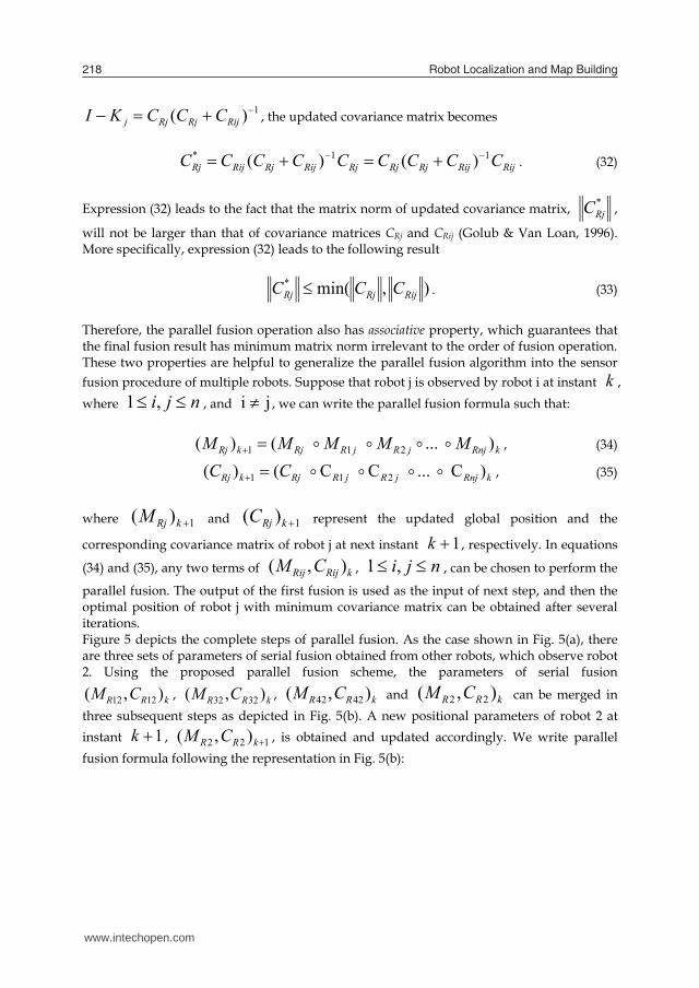
RijRijRjRjRjRijRjRijRj CCCCCCCCC 11* )()( . (32)
Expression (32) leads to the fact that the matrix norm of updated covariance matrix, *RjC ,
will not be larger than that of covariance matrices CRj and CRij (Golub & Van Loan, 1996). More specifically, expression (32) leads to the following result
),min(*RijRjRj CCC . (33)
Therefore, the parallel fusion operation also has associative property, which guarantees that the final fusion result has minimum matrix norm irrelevant to the order of fusion operation. These two properties are helpful to generalize the parallel fusion algorithm into the sensor fusion procedure of multiple robots. Suppose that robot j is observed by robot i at instant k , where nji ,1 , and ji , we can write the parallel fusion formula such that: kRnjjRjRRjkRj MMMMM )...()( 211 , (34)
kRnjjRjRRjkRj CC )C...CC()( 211 , (35)
where 1)( kRjM and 1)( kRjC represent the updated global position and the
corresponding covariance matrix of robot j at next instant 1k , respectively. In equations
(34) and (35), any two terms of kRijRij CM ),( , nji ,1 , can be chosen to perform the
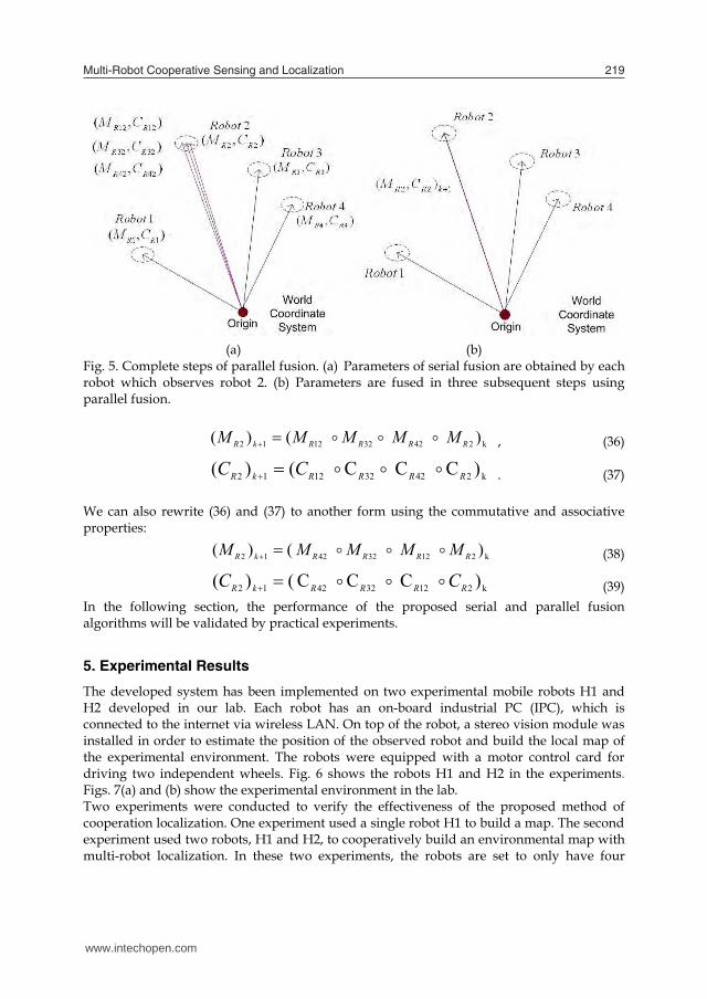
parallel fusion. The output of the first fusion is used as the input of next step, and then the optimal position of robot j with minimum covariance matrix can be obtained after several iterations. Figure 5 depicts the complete steps of parallel fusion. As the case shown in Fig. 5(a), there are three sets of parameters of serial fusion obtained from other robots, which observe robot 2. Using the proposed parallel fusion scheme, the parameters of serial fusion
kRR CM ),( 1212 , kRR CM ),( 3232 , kRR CM ),( 4242 and kRR CM ),( 22 can be merged in three subsequent steps as depicted in Fig. 5(b). A new positional parameters of robot 2 at instant 1k , 122 ),( kRR CM , is obtained and updated accordingly. We write parallel fusion formula following the representation in Fig. 5(b):
(a) (b)
Fig. 5. Complete steps of parallel fusion. (a) Parameters of serial fusion are obtained by each robot which observes robot 2. (b) Parameters are fused in three subsequent steps using parallel fusion.
)()( k242321212 RRRRkR MMMMM , (36)
)CCC()( k242321212 RRRRkR CC . (37) We can also rewrite (36) and (37) to another form using the commutative and associative properties:
)()( k212324212 RRRRkR MMMMM (38)
)CCC()( k212324212 RRRRkR CC (39) In the following section, the performance of the proposed serial and parallel fusion algorithms will be validated by practical experiments.
5. Experimental Results
The developed system has been implemented on two experimental mobile robots H1 and H2 developed in our lab. Each robot has an on-board industrial PC (IPC), which is connected to the internet via wireless LAN. On top of the robot, a stereo vision module was installed in order to estimate the position of the observed robot and build the local map of the experimental environment. The robots were equipped with a motor control card for driving two independent wheels. Fig. 6 shows the robots H1 and H2 in the experiments. Figs. 7(a) and (b) show the experimental environment in the lab. Two experiments were conducted to verify the effectiveness of the proposed method of cooperation localization. One experiment used a single robot H1 to build a map. The second experiment used two robots, H1 and H2, to cooperatively build an environmental map with multi-robot localization. In these two experiments, the robots are set to only have four
www.intechopen.com
Multi-Robot Cooperative Sensing and Localization 219
1)( RijRjRjj CCCKI , the updated covariance matrix becomes
RijRijRjRjRjRijRjRijRj CCCCCCCCC 11* )()( . (32)
Expression (32) leads to the fact that the matrix norm of updated covariance matrix, *RjC ,
will not be larger than that of covariance matrices CRj and CRij (Golub & Van Loan, 1996). More specifically, expression (32) leads to the following result
),min(*RijRjRj CCC . (33)
Therefore, the parallel fusion operation also has associative property, which guarantees that the final fusion result has minimum matrix norm irrelevant to the order of fusion operation. These two properties are helpful to generalize the parallel fusion algorithm into the sensor fusion procedure of multiple robots. Suppose that robot j is observed by robot i at instant k , where nji ,1 , and ji , we can write the parallel fusion formula such that: kRnjjRjRRjkRj MMMMM )...()( 211 , (34)
kRnjjRjRRjkRj CC )C...CC()( 211 , (35)
where 1)( kRjM and 1)( kRjC represent the updated global position and the
corresponding covariance matrix of robot j at next instant 1k , respectively. In equations
(34) and (35), any two terms of kRijRij CM ),( , nji ,1 , can be chosen to perform the
parallel fusion. The output of the first fusion is used as the input of next step, and then the optimal position of robot j with minimum covariance matrix can be obtained after several iterations. Figure 5 depicts the complete steps of parallel fusion. As the case shown in Fig. 5(a), there are three sets of parameters of serial fusion obtained from other robots, which observe robot 2. Using the proposed parallel fusion scheme, the parameters of serial fusion
kRR CM ),( 1212 , kRR CM ),( 3232 , kRR CM ),( 4242 and kRR CM ),( 22 can be merged in three subsequent steps as depicted in Fig. 5(b). A new positional parameters of robot 2 at instant 1k , 122 ),( kRR CM , is obtained and updated accordingly. We write parallel fusion formula following the representation in Fig. 5(b):
(a) (b)
Fig. 5. Complete steps of parallel fusion. (a) Parameters of serial fusion are obtained by each robot which observes robot 2. (b) Parameters are fused in three subsequent steps using parallel fusion.
)()( k242321212 RRRRkR MMMMM , (36)
)CCC()( k242321212 RRRRkR CC . (37) We can also rewrite (36) and (37) to another form using the commutative and associative properties:
)()( k212324212 RRRRkR MMMMM (38)
)CCC()( k212324212 RRRRkR CC (39) In the following section, the performance of the proposed serial and parallel fusion algorithms will be validated by practical experiments.
5. Experimental Results
The developed system has been implemented on two experimental mobile robots H1 and H2 developed in our lab. Each robot has an on-board industrial PC (IPC), which is connected to the internet via wireless LAN. On top of the robot, a stereo vision module was installed in order to estimate the position of the observed robot and build the local map of the experimental environment. The robots were equipped with a motor control card for driving two independent wheels. Fig. 6 shows the robots H1 and H2 in the experiments. Figs. 7(a) and (b) show the experimental environment in the lab. Two experiments were conducted to verify the effectiveness of the proposed method of cooperation localization. One experiment used a single robot H1 to build a map. The second experiment used two robots, H1 and H2, to cooperatively build an environmental map with multi-robot localization. In these two experiments, the robots are set to only have four
www.intechopen.com

Robot Localization and Map Building220
orientation angles: 0o, 90o, 180o, and 270o. Therefore, the orientation of the robot can be supposed to be known without uncertainty. This assumption leads a simplified implementation of the proposed algorithm, which does not consider the information of robot orientation. For instance, expressions (7) and (8) can be simplified such that
Eij
rr
rrRi
EijRi
EijRiRij MM
MMgMMf
yx
M
cossinsincos
),(),(
, (40)
T
Eij
RiRij J
CC
JC
22
22
00
, (41)
with
r
rRi y
xM ,
e
eEij y
xM , and
rr
rrJ
cossin10sincos01
.
However, the performance and convergence of the proposed algorithm will not be influenced. In the following, these two experimental results are compared and discussed.
1
2
3
4
5
Fig. 6. Front view of robots H1 and H2. H1 on the left is with a blue ball and H2 with a red ball. Both robots are equipped with (1) a blue or red color ball, (2) stereo vision module with two CMOS cameras, (3) motion control module, (4) wireless LAN card, (5) on-board IPC.
(a) (b)
Fig. 7. Experimental environment. Remark 2: The covariance matrices CRi and CEij in (41) are calibrated by practical testing for each robot. In the experiments, the covariance matrices for each robot are calibrated by
Robot H1:
0.02480
00.0596)(1
)1(1
kR
kR CC and
0.05320
00.043012EC ,
Robot H2:
0.05130
00.0478)(2
)1(2
kR
kR CC and
0.07930
00.059521EC ,
where )(kRiC denotes the positional covariance matrix of robot Ri at time step k and will be
accumulated step-by-step when the robot travels due to the odometry measurement noise. Experiment 1: Single robot localization and map-building In this part, robot H1 was commanded to build a map of the environment alone. The localization of the robot is using the information from odometry only such that
rkr
kr
kr vxx cos)()()1( , and r
kr
kr
kr vyy sin)()()1( , (42)
where )(krv is the linear velocity of the robot at time step k. The linear velocity is calculated
by counting encoder signals from two driving wheels. Because of
}270,180,90,0{ r , the angular velocity of the robot can be ignored in the experiments.
www.intechopen.com

Multi-Robot Cooperative Sensing and Localization 221
orientation angles: 0o, 90o, 180o, and 270o. Therefore, the orientation of the robot can be supposed to be known without uncertainty. This assumption leads a simplified implementation of the proposed algorithm, which does not consider the information of robot orientation. For instance, expressions (7) and (8) can be simplified such that
Eij
rr
rrRi
EijRi
EijRiRij MM
MMgMMf
yx
M
cossinsincos
),(),(
, (40)
T
Eij
RiRij J
CC
JC
22
22
00
, (41)
with
r
rRi y
xM ,
e
eEij y
xM , and
rr
rrJ
cossin10sincos01
.
However, the performance and convergence of the proposed algorithm will not be influenced. In the following, these two experimental results are compared and discussed.
1
2
3
4
5
Fig. 6. Front view of robots H1 and H2. H1 on the left is with a blue ball and H2 with a red ball. Both robots are equipped with (1) a blue or red color ball, (2) stereo vision module with two CMOS cameras, (3) motion control module, (4) wireless LAN card, (5) on-board IPC.
(a) (b)
Fig. 7. Experimental environment. Remark 2: The covariance matrices CRi and CEij in (41) are calibrated by practical testing for each robot. In the experiments, the covariance matrices for each robot are calibrated by
Robot H1:
0.02480
00.0596)(1
)1(1
kR
kR CC and
0.05320
00.043012EC ,
Robot H2:
0.05130
00.0478)(2
)1(2
kR
kR CC and
0.07930
00.059521EC ,
where )(kRiC denotes the positional covariance matrix of robot Ri at time step k and will be
accumulated step-by-step when the robot travels due to the odometry measurement noise. Experiment 1: Single robot localization and map-building In this part, robot H1 was commanded to build a map of the environment alone. The localization of the robot is using the information from odometry only such that
rkr
kr
kr vxx cos)()()1( , and r
kr
kr
kr vyy sin)()()1( , (42)
where )(krv is the linear velocity of the robot at time step k. The linear velocity is calculated
by counting encoder signals from two driving wheels. Because of
}270,180,90,0{ r , the angular velocity of the robot can be ignored in the experiments.
www.intechopen.com

Robot Localization and Map Building222
Fig. 8 shows the experimental results. In Fig. 8, the dotted lines represent actual environmental shape. Solid lines show the map established by the robot H1. Six positions A, B, C, D, E and F were recorded as the robot moved around the environment. Table 2 shows the position parameters of H1 of these points. In Table 2, it is observed that as H1 moves through point A to F subsequently, the standard deviations of x and y coordinates become larger and larger. This means that H1 is getting lost of its position estimation because the accumulated error from dead reckoning. From Table 2, we also see that the standard deviations of from A to F are increasing. This implies the error between the actual and estimated positions becomes larger as the robot travels further. Experiment 2: Cooperative visual localization and map-building In this part, robots H1 and H2 worked together to cooperatively localize each other and built a map of the environment. Fig. 9 shows the experimental results. In Fig. 9(a), seven positions of H1 were recorded. In Fig. 9(b), five positions of H2 were recorded. The black points are the recorded trajectory of H1 and H2, respectively. The dotted lines are actual environmental shape. Solid lines represent the maps established by H1 and H2 respectively. In this experiment, H1 was observed by H2 at point D of H1. The robot H2 was observed by H1 at points C and E of H2.
Fig. 8. Map-building result of single robot H1. The position estimation results of H1 and H2 in experiment 2 are shown in Table 3 and 4, respectively. From Table 3, we see that when H1 moved through point A, B and C subsequently, the standard deviations of x and y coordinates increase. However, when H1 moved to point D and was observed by H2, parallel fusion of H1 occurred. So the position uncertainty of robot H1 and the error between actual and estimated position became smaller as expected. The similar results also can be confirmed for robot H2. As shown in Table 4, since H2 was observed by H1 at points C and E, the position uncertainty and the positional error were reduced at point C and E as expected.
Table 2. Position parameters of H1 in experiment1.
Fig. 9. Map-building results in experiment 2: (a) by H1 (b) by H2.
Table 3. Position parameters of H1 in experiment 2.
www.intechopen.com

Multi-Robot Cooperative Sensing and Localization 223
Fig. 8 shows the experimental results. In Fig. 8, the dotted lines represent actual environmental shape. Solid lines show the map established by the robot H1. Six positions A, B, C, D, E and F were recorded as the robot moved around the environment. Table 2 shows the position parameters of H1 of these points. In Table 2, it is observed that as H1 moves through point A to F subsequently, the standard deviations of x and y coordinates become larger and larger. This means that H1 is getting lost of its position estimation because the accumulated error from dead reckoning. From Table 2, we also see that the standard deviations of from A to F are increasing. This implies the error between the actual and estimated positions becomes larger as the robot travels further. Experiment 2: Cooperative visual localization and map-building In this part, robots H1 and H2 worked together to cooperatively localize each other and built a map of the environment. Fig. 9 shows the experimental results. In Fig. 9(a), seven positions of H1 were recorded. In Fig. 9(b), five positions of H2 were recorded. The black points are the recorded trajectory of H1 and H2, respectively. The dotted lines are actual environmental shape. Solid lines represent the maps established by H1 and H2 respectively. In this experiment, H1 was observed by H2 at point D of H1. The robot H2 was observed by H1 at points C and E of H2.
Fig. 8. Map-building result of single robot H1. The position estimation results of H1 and H2 in experiment 2 are shown in Table 3 and 4, respectively. From Table 3, we see that when H1 moved through point A, B and C subsequently, the standard deviations of x and y coordinates increase. However, when H1 moved to point D and was observed by H2, parallel fusion of H1 occurred. So the position uncertainty of robot H1 and the error between actual and estimated position became smaller as expected. The similar results also can be confirmed for robot H2. As shown in Table 4, since H2 was observed by H1 at points C and E, the position uncertainty and the positional error were reduced at point C and E as expected.
Table 2. Position parameters of H1 in experiment1.
Fig. 9. Map-building results in experiment 2: (a) by H1 (b) by H2.
Table 3. Position parameters of H1 in experiment 2.
www.intechopen.com

Robot Localization and Map Building224
Table 4. Position parameters of H2 in experiment 2.
Fig. 10. Cooperative map-building result of H1 and H2. Therefore, the experimental results validate that the proposed cooperative localization algorithm effectively reduces the position error of each robot in the cooperative robotic system. Fig. 10 shows the integrated result of Fig. 9 constructed in the robot server through cooperation of robots H1 and H2. In Fig. 10, the gray lines represent actual environmental shape. Solid lines represent the global map established by robot H1 and H2 collaboratively. Because the position error of each robot was reduced by the cooperative localization, the error of the map also became smaller compared with the case in Fig. 8 without sensor fusion.
6. Conclusions
In this chapter, we presented a multi-robot cooperative localization scheme which does not restrict the number of robots in the system and guarantees the optimal fusion results with minimum covariance matrix. In this scheme, each robot is equipped with a stereo vision
system to recognize the individual robot and find important features in environment. This is advantageous compared to a robotic system with sonar or laser sensors, where the robots have practical limitations in recognizing more than two robot-teammates. From practical experiments, we observe that parallel fusion can effectively reduce robot positional uncertainty as expected. Using serial and parallel fusion, one can increase the accuracy of robot localization and reduce the errors in map-building. In the future, we will first extend the experiments to a more complex environment with more robots. Theoretical improvements will also be investigated, such as the information transmission issue between each robot teammate, and how often the robots need to observe each other.
7. Acknowledgnent This work was partly supported by the National Science Council of Taiwan, ROC under grant NSC 96-2628-E-009-162 and NSC 94-2218-E-009-008.
8. References
Fox, D.; Burgard, W.; Thrun, S. & Cremers, A.B. (1998). Position estimation for mobile robots in dynamic environments. Proceedings of Fifteenth National Conference on Artificial Intelligence, Madison, Wisconsin, pp. 983-988
Fox, D.; Burgard, W.; Kruppa, H. & Thrun, S. (1999). Collaborative multi-robot localization. Proceedings of German Conference on Artificial Intelligence, Bonn, Germany, pp. 255-266
Gamini Dissanayake, M. W. M.; Newman, P.; Clark, S.; Durrant-Whyte, H. F. & Csorba, M. (2001). A solution to the simultaneous localization and map-building (SLAM) problem. IEEE Transactions on Robotics and Automation, Vol. 17, No. , pp. 229-241
Golub, G. H. & Van Loan, C. F. (1996). Matrix computations – third edition, Baltimore: The Johns Hopkins University Press
Jennings, C.; Murray, D. & Little, J. J. (1999). Cooperative robot localization with vision-based mapping. Proceedings of IEEE International Conference on Robotics and Automation, Detroit, USA, pp. 2659-2665
Nieto, J.; Guivant, J.; Nebot, E. & Thrun, S. (2002). FastSLAM: A factored solution to the simultaneous localization and mapping problem. Proceedings of Eighteenth National Conference on Artificial Intelligence, Alberta, Canada, pp. 593-598
Nieto, J.; Guivant, J.; Nebot, E. & Thrun, S. (2003). Real time data association for FastSLAM. Proceedings of IEEE International Conference on Robotics and Automation, Taipei, Taiwan, pp. 412-418
Parker, L. E. (1998). ALLIANCE: An architecture for fault tolerant multirobot cooperation. IEEE Transactions on Robotics and Automation, Vol. 14, No. 2, pp. 220-240
Rekleitis, I. M.; Dudek, G. & Milios, E. (2003). Probabilistic cooperative localization and mapping in practice. Proceedings of IEEE International Conference on Robotics and Automation, Taipei, Taiwan, pp. 1907-1912
Roumeliotis, S. I. & Bekey, G. A. (2002). Distributed multi-robot localization. IEEE Transactions on Robotics and Automation, Vol. 18, No. 5, pp. 781-795
Smith, R. C. & Cheeseman, P. (1986). On the representation and estimation of spatial uncertainty. The International Journal of Robotics Research, Vol. 5, No. 4, pp. 56-68
www.intechopen.com

Multi-Robot Cooperative Sensing and Localization 225
Table 4. Position parameters of H2 in experiment 2.
Fig. 10. Cooperative map-building result of H1 and H2. Therefore, the experimental results validate that the proposed cooperative localization algorithm effectively reduces the position error of each robot in the cooperative robotic system. Fig. 10 shows the integrated result of Fig. 9 constructed in the robot server through cooperation of robots H1 and H2. In Fig. 10, the gray lines represent actual environmental shape. Solid lines represent the global map established by robot H1 and H2 collaboratively. Because the position error of each robot was reduced by the cooperative localization, the error of the map also became smaller compared with the case in Fig. 8 without sensor fusion.
6. Conclusions
In this chapter, we presented a multi-robot cooperative localization scheme which does not restrict the number of robots in the system and guarantees the optimal fusion results with minimum covariance matrix. In this scheme, each robot is equipped with a stereo vision
system to recognize the individual robot and find important features in environment. This is advantageous compared to a robotic system with sonar or laser sensors, where the robots have practical limitations in recognizing more than two robot-teammates. From practical experiments, we observe that parallel fusion can effectively reduce robot positional uncertainty as expected. Using serial and parallel fusion, one can increase the accuracy of robot localization and reduce the errors in map-building. In the future, we will first extend the experiments to a more complex environment with more robots. Theoretical improvements will also be investigated, such as the information transmission issue between each robot teammate, and how often the robots need to observe each other.
7. Acknowledgnent This work was partly supported by the National Science Council of Taiwan, ROC under grant NSC 96-2628-E-009-162 and NSC 94-2218-E-009-008.
8. References
Fox, D.; Burgard, W.; Thrun, S. & Cremers, A.B. (1998). Position estimation for mobile robots in dynamic environments. Proceedings of Fifteenth National Conference on Artificial Intelligence, Madison, Wisconsin, pp. 983-988
Fox, D.; Burgard, W.; Kruppa, H. & Thrun, S. (1999). Collaborative multi-robot localization. Proceedings of German Conference on Artificial Intelligence, Bonn, Germany, pp. 255-266
Gamini Dissanayake, M. W. M.; Newman, P.; Clark, S.; Durrant-Whyte, H. F. & Csorba, M. (2001). A solution to the simultaneous localization and map-building (SLAM) problem. IEEE Transactions on Robotics and Automation, Vol. 17, No. , pp. 229-241
Golub, G. H. & Van Loan, C. F. (1996). Matrix computations – third edition, Baltimore: The Johns Hopkins University Press
Jennings, C.; Murray, D. & Little, J. J. (1999). Cooperative robot localization with vision-based mapping. Proceedings of IEEE International Conference on Robotics and Automation, Detroit, USA, pp. 2659-2665
Nieto, J.; Guivant, J.; Nebot, E. & Thrun, S. (2002). FastSLAM: A factored solution to the simultaneous localization and mapping problem. Proceedings of Eighteenth National Conference on Artificial Intelligence, Alberta, Canada, pp. 593-598
Nieto, J.; Guivant, J.; Nebot, E. & Thrun, S. (2003). Real time data association for FastSLAM. Proceedings of IEEE International Conference on Robotics and Automation, Taipei, Taiwan, pp. 412-418
Parker, L. E. (1998). ALLIANCE: An architecture for fault tolerant multirobot cooperation. IEEE Transactions on Robotics and Automation, Vol. 14, No. 2, pp. 220-240
Rekleitis, I. M.; Dudek, G. & Milios, E. (2003). Probabilistic cooperative localization and mapping in practice. Proceedings of IEEE International Conference on Robotics and Automation, Taipei, Taiwan, pp. 1907-1912
Roumeliotis, S. I. & Bekey, G. A. (2002). Distributed multi-robot localization. IEEE Transactions on Robotics and Automation, Vol. 18, No. 5, pp. 781-795
Smith, R. C. & Cheeseman, P. (1986). On the representation and estimation of spatial uncertainty. The International Journal of Robotics Research, Vol. 5, No. 4, pp. 56-68
www.intechopen.com
Robot Localization and Map Building226
Stroupe, A. W. & Balch, T. (2002). Collaborative probabilistic constraint-based landmark localization. Proceedings of IEEE/RSJ International Conference on Intelligent Robots and Systems, Switzerland, pp. 447-453
Stroupe, A. W. & Martin, C. (2001). Distributed sensor fusion for object position estimation by multi-robot systems. Proceedings of IEEE International Conference on Robotics and Automation, Seoul, Korea, pp. 1092-1098
Thrun, S.; Fox, D.; Burgard, W. & Dellaert, F. (2001). Robust monte carlo localization for mobile robots, Artificial Intelligence, Vol. 128, No. 1-2, pp. 99-141
Weigel, T.; Gutmann, J.-S.; Dietl, M.; Kleiner A. & Nebel, B. (2002). CS Freiguring: Coordinating robots for successful soccer playing. IEEE Transactions on Robotics and Automation, Vol. 18, No. 5, pp. 685-699
Zhang, L. & Ghosh, B. K. (2000). Line segment based map building and localization using 2D laser rangefinder. Proceedings of IEEE International Conference on Robotics and Automation, San Francisco, USA, pp. 2538-2543
www.intechopen.com

Robot Localization and Map BuildingEdited by Hanafiah Yussof
ISBN 978-953-7619-83-1Hard cover, 578 pagesPublisher InTechPublished online 01, March, 2010Published in print edition March, 2010
InTech EuropeUniversity Campus STeP Ri Slavka Krautzeka 83/A 51000 Rijeka, Croatia Phone: +385 (51) 770 447 Fax: +385 (51) 686 166www.intechopen.com
InTech ChinaUnit 405, Office Block, Hotel Equatorial Shanghai No.65, Yan An Road (West), Shanghai, 200040, China
Phone: +86-21-62489820 Fax: +86-21-62489821
Localization and mapping are the essence of successful navigation in mobile platform technology. Localizationis a fundamental task in order to achieve high levels of autonomy in robot navigation and robustness in vehiclepositioning. Robot localization and mapping is commonly related to cartography, combining science, techniqueand computation to build a trajectory map that reality can be modelled in ways that communicate spatialinformation effectively. This book describes comprehensive introduction, theories and applications related tolocalization, positioning and map building in mobile robot and autonomous vehicle platforms. It is organized intwenty seven chapters. Each chapter is rich with different degrees of details and approaches, supported byunique and actual resources that make it possible for readers to explore and learn the up to date knowledge inrobot navigation technology. Understanding the theory and principles described in this book requires amultidisciplinary background of robotics, nonlinear system, sensor network, network engineering, computerscience, physics, etc.
How to referenceIn order to correctly reference this scholarly work, feel free to copy and paste the following:
Kai-Tai Song, Chi-Yi Tsai and Cheng-Hsien Chiu Huang (2010). Multi-Robot Cooperative Sensin andLocalization, Robot Localization and Map Building, Hanafiah Yussof (Ed.), ISBN: 978-953-7619-83-1, InTech,Available from: http://www.intechopen.com/books/robot-localization-and-map-building/multi-robot-cooperative-sensin-and-localization

© 2010 The Author(s). Licensee IntechOpen. This chapter is distributedunder the terms of the Creative Commons Attribution-NonCommercial-ShareAlike-3.0 License, which permits use, distribution and reproduction fornon-commercial purposes, provided the original is properly cited andderivative works building on this content are distributed under the samelicense.