Embed Size (px)
Citation preview
EPJ Appl. Metamat. 7, 8 (2020)© P. Bora et al., published by EDP Sciences, 2020https://doi.org/10.1051/epjam/2020008
Available online at:epjam.edp-open.org
RESEARCH ARTICLE
X-band metamaterial absorbers based on reduced grapheneoxide-silicon carbide-linear low density polyethylene compositePankaj Bora1, Utpal Jyoti Mahanta2, Jayanta Kumar Sarmah3, and Jyoti Prasad Gogoi1,*
1 Department of Physics, Kaziranga University, Jorhat 785006, India2 Department of Physics, Sibsagar College, Sivasagar 785665, India3 Department of Chemistry, Kaziranga University, Jorhat 785006, India
* e-mail: j
This is anO
Received: 13 October 2020 / Accepted: 30 November 2020
Abstract.Graphene oxide obtained by Hummer’s method is used to synthesize reduced graphene oxide (RGO)using chemical and thermal treatment method. Flexible composites of RGO-Silicon carbide (SiC)-Low densitypolyethylene (LLDPE) in different wt.% ratios of fillers are characterized for complex permittivity andpermeability in X-band. Ametamaterial design of ring shapedwith four stripe structure is designed on developedsubstrate as well as standard FR4 substrate and simulated using EM simulator, CST Microwave Studio.Simulated results showed shifting of resonant peak frequency from C-band frequency for FR4 substrate toX-band for developed substrates signifying a role of microwave constitutive properties of the dielectric spacer.The fabricated metamaterial structure on RGO-SiC-LLDPE composite of thickness 0.7mm shows a S11 ∼�25 dB at 10.7GHz with maximum absorption of 96.7%. Thus, the developed meta-material design showing apotential application in microwave applications.
Keywords: Reduced graphene oxide / silicon carbide / meta material / microwave absorber
1 Introduction
Simultaneous operation of microwave components in highfrequencies wireless communication system experiencedelectromagnetic interference (EMI) and demands micro-wave absorber to ascertain electromagnetic compatibilityissues [1]. Conventional conductor backed microwaveabsorbers (MA) depends on its electromagnetic constitu-tive parameters viz. complex permittivity er(v) andpermeability mr(v), and thickness (d) and the performanceefficiency is estimated by reflection loss (RLc) usingtransmission line model [2] and expressed as
RLc ¼ 20log Zin vð Þ�377Zin vð Þþ377
������ where Zin vð Þ ¼ hi
Zi�1þhitanh gidihiþZi�1tanhgidi
is
the input impedance. The challenges in conventional MAare adequate absorption ∼�10 dB within limited thicknessand specific absorption properties of selective absorbingmaterial fulfilling impedance matching to free space [3].Meta-material absorber (MMA) due to their exoticelectromagnetic properties derived from its unit cellgeometric configuration finds wide applications in millime-ter [4], the microwave [5,6], and the THz [7] regimes.Conventional MMA are composed of a tri-layer systemconsist of a metallic top layer periodically patterned in
penAccess article distributed under the terms of the CreativeComwhich permits unrestricted use, distribution, and reproduction
various shape viz. ring, cross, patch etc., a continuousmetallic plates bottom layer and a dielectric spacerbetween them and the absorption mechanism is thecoupling between the incident EM field and EM fieldinduced by resonators as demonstrated by Landy et al. [5].Meta-material structure described as effective mediumparameters er (eff) (v) and mr (eff) (v) facilating surfaceimpedance matching to free space as Z vð Þ ¼
ffiffiffiffiffiffiffiffiffiffiffiffiffimr effð Þm0
er effð Þe0
q
and its reflectivity jS11 vð Þj ¼ Z vð Þ�Z0
Z vð ÞþZ0
������ ! 0 and thereby
increasing the absorptivity A (v) as indicated by therelation A (v)= 1� |S11 (v) |
2� |S21 (v) |2= 1� |S11 (v) |
2,since transmission is not allowed by back metallic plane.Further, the dielectric spacer contribute the dielectric lossto dissipate the EM wave energy absorbed [5] andincreasing the dielectric thickness (d) increase the absorp-tion bandwidth (B) expressed [8] asB≅ 4R0
vdjmr�erjwhereR0 isthe lowest possible reflectivity. Extensive work has beenperformed on development of multiband and broadbandMMA with changing MM’s design, employing ultrathinresistive spacer sheets and MM design [9–17]. Mostly, thereported research on MMA are rigid dielectric substrateslike FR4, silicon wafers and rigid metallic (Cu) back layers[18–27] and emphasize on meta material unit cell designwith limited study on the role of dielectric spacer propertieson microwave absorption. A flexible meta-material
monsAttribution License (https://creativecommons.org/licenses/by/4.0),in any medium, provided the original work is properly cited.
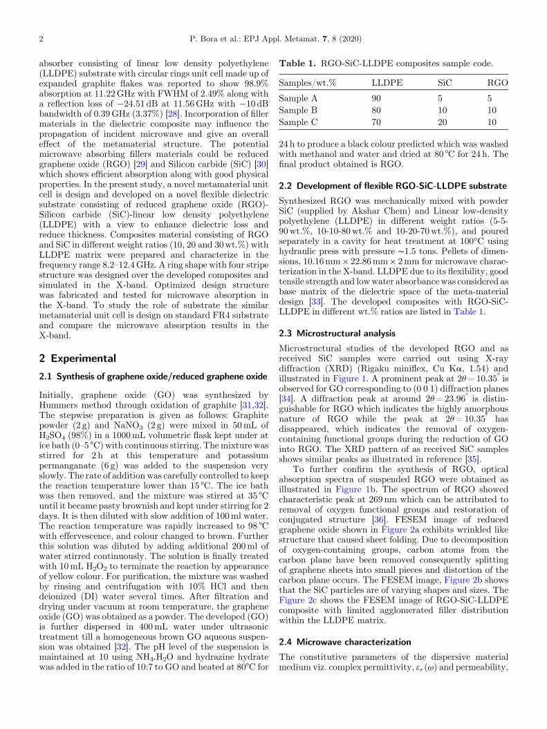
Table 1. RGO-SiC-LLDPE composites sample code.
Samples/wt.% LLDPE SiC RGO
Sample A 90 5 5Sample B 80 10 10Sample C 70 20 10
2 P. Bora et al.: EPJ Appl. Metamat. 7, 8 (2020)
absorber consisting of linear low density polyethylene(LLDPE) substrate with circular rings unit cell made up ofexpanded graphite flakes was reported to show 98.9%absorption at 11.22GHz with FWHM of 2.49% along witha reflection loss of �24.51 dB at 11.56GHz with �10 dBbandwidth of 0.39GHz (3.37%) [28]. Incorporation of fillermaterials in the dielectric composite may influence thepropagation of incident microwave and give an overalleffect of the metamaterial structure. The potentialmicrowave absorbing fillers materials could be reducedgraphene oxide (RGO) [29] and Silicon carbide (SiC) [30]which shows efficient absorption along with good physicalproperties. In the present study, a novel metamaterial unitcell is design and developed on a novel flexible dielectricsubstrate consisting of reduced graphene oxide (RGO)-Silicon carbide (SiC)-linear low density polyethylene(LLDPE) with a view to enhance dielectric loss andreduce thickness. Composites material consisting of RGOand SiC in different weight ratios (10, 20 and 30wt.%) withLLDPE matrix were prepared and characterize in thefrequency range 8.2–12.4GHz. A ring shape with four stripestructure was designed over the developed composites andsimulated in the X-band. Optimized design structurewas fabricated and tested for microwave absorption inthe X-band. To study the role of substrate the similarmetamaterial unit cell is design on standard FR4 substrateand compare the microwave absorption results in theX-band.
2 Experimental
2.1 Synthesis of graphene oxide/reduced graphene oxide
Initially, graphene oxide (GO) was synthesized byHummers method through oxidation of graphite [31,32].The stepwise preparation is given as follows: Graphitepowder (2 g) and NaNO3 (2 g) were mixed in 50mL ofH2SO4 (98%) in a 1000mL volumetric flask kept under atice bath (0–5 °C)with continuous stirring. Themixture wasstirred for 2 h at this temperature and potassiumpermanganate (6 g) was added to the suspension veryslowly. The rate of addition was carefully controlled to keepthe reaction temperature lower than 15 °C. The ice bathwas then removed, and the mixture was stirred at 35 °Cuntil it became pasty brownish and kept under stirring for 2days. It is then diluted with slow addition of 100ml water.The reaction temperature was rapidly increased to 98 °Cwith effervescence, and colour changed to brown. Furtherthis solution was diluted by adding additional 200ml ofwater stirred continuously. The solution is finally treatedwith 10mL H2O2 to terminate the reaction by appearanceof yellow colour. For purification, the mixture was washedby rinsing and centrifugation with 10% HCl and thendeionized (DI) water several times. After filtration anddrying under vacuum at room temperature, the grapheneoxide (GO) was obtained as a powder. The developed (GO)is further dispersed in 400mL water under ultrasonictreatment till a homogeneous brown GO aqueous suspen-sion was obtained [32]. The pH level of the suspension ismaintained at 10 using NH3.H2O and hydrazine hydratewas added in the ratio of 10:7 to GO and heated at 80°C for
24 h to produce a black colour predicted which was washedwith methanol and water and dried at 80 °C for 24 h. Thefinal product obtained is RGO.
2.2 Development of flexible RGO-SiC-LLDPE substrate
Synthesized RGO was mechanically mixed with powderSiC (supplied by Akshar Chem) and Linear low-densitypolyethylene (LLDPE) in different weight ratios (5-5-90wt.%, 10-10-80wt.% and 10-20-70wt.%), and pouredseparately in a cavity for heat treatment at 100°C usinghydraulic press with pressure ∼1.5 tons. Pellets of dimen-sions, 10.16mm� 22.86mm� 2mm for microwave charac-terization in the X-band. LLDPE due to its flexibility, goodtensile strength and lowwater absorbancewas considered asbase matrix of the dielectric space of the meta-materialdesign [33]. The developed composites with RGO-SiC-LLDPE in different wt.% ratios are listed in Table 1.
2.3 Microstructural analysis
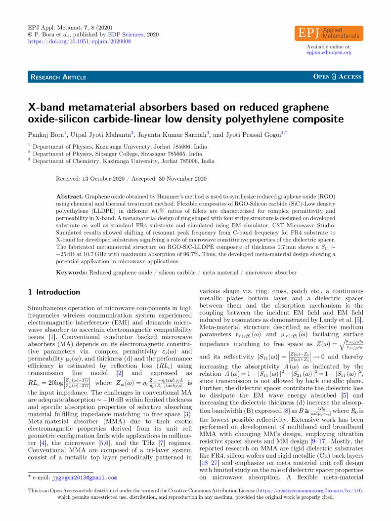
Microstructural studies of the developed RGO and asreceived SiC samples were carried out using X-raydiffraction (XRD) (Rigaku miniflex, Cu Ka, 1.54) andillustrated in Figure 1. A prominent peak at 2u=10.35° isobserved for GO corresponding to (0 0 1) diffraction planes[34]. A diffraction peak at around 2u=23.96° is distin-guishable for RGO which indicates the highly amorphousnature of RGO while the peak at 2u=10.35° hasdisappeared, which indicates the removal of oxygen-containing functional groups during the reduction of GOinto RGO. The XRD pattern of as received SiC samplesshows similar peaks as illustrated in reference [35].
To further confirm the synthesis of RGO, opticalabsorption spectra of suspended RGO were obtained asillustrated in Figure 1b. The spectrum of RGO showedcharacteristic peak at 269 nm which can be attributed toremoval of oxygen functional groups and restoration ofconjugated structure [36]. FESEM image of reducedgraphene oxide shown in Figure 2a exhibits wrinkled likestructure that caused sheet folding. Due to decompositionof oxygen-containing groups, carbon atoms from thecarbon plane have been removed consequently splittingof graphene sheets into small pieces and distortion of thecarbon plane occurs. The FESEM image, Figure 2b showsthat the SiC particles are of varying shapes and sizes. TheFigure 2c shows the FESEM image of RGO-SiC-LLDPEcomposite with limited agglomerated filler distributionwithin the LLDPE matrix.
2.4 Microwave characterization
The constitutive parameters of the dispersive materialmedium viz. complex permittivity, er (v) and permeability,
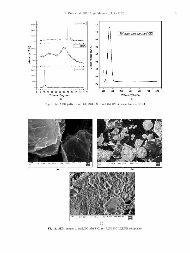
Fig. 1. (a) XRD patterns of GO, RGO, SiC and (b) UV–Vis spectrum of RGO.
Fig. 2. SEM images of (a)RGO, (b) SiC, (c) RGO-SiC-LLDPE composite.
P. Bora et al.: EPJ Appl. Metamat. 7, 8 (2020) 3
Fig. 3. Complex permittivity of RGO-SiC-LLDPE composite; (a) real permittivity and (b) imaginary permittivity.
4 P. Bora et al.: EPJ Appl. Metamat. 7, 8 (2020)
mr (v) determine the propagation of the electromagneticwave through the medium and in designing meta-materialstructure the substrate may take part a major role inmicrowave absorption. Measurement of er (v) and mr (v)values of the developed composites samples (A, B C) werecarried out using Nicolson and Ross [37] method employingAgilent 85071E material measurement software compati-ble with Agilent E8362C VNA in the X-band, as shown inFigure 3. The composites are found to be non-magnetic asindicated by (mr (v)= 1� j.0). As observed fromFigures 3aand 3b, er
/(v) and er//(v) values enhance over the X-band
with increase in filler concentrations (RGO-SiC) in thecomposite. The values of er
/(v) Figure 3a increase from 2.0for the composite sample A (RGO-SiC, 10%) to 3.7 for thecomposites sample C (RGO-SiC, 20–10%) at 8.2GHz.Figure 3a also indicates that the er
/(v) values for thecomposites sample A(RGO-SiC, 10%) and B (RGO-SiC,20%) with lower concentration of fillers are almostfrequency independent in the entire range of X-band.However, there is a declining trend in the values of real partof permittivity er
/(v) of the sample C with higher amountof filler (RGO-SiC, 20–10%) from 3.7 (8.2GHz) to 2.5 at12.4GHz with frequency. Similar trend has been observedin Figure 3b for the values of imaginary part of permittivityer//(v), the er
//(v) values for the composite samples A andB with lower concentration of fillers exhibit more or lessfrequency independent character in the frequency range8.2–12.4GHz. However with fillers concentration in thesamples, er
//(v) values rise from 0.1 (sample A (RGO-SiC,10%)) to 0.5 (sampleC (RGO-SiC, 20–10%)) at 8.2GHz.Similar to er
/(v) values, the er//(v) values of sample C too
exhibits frequency dispersive behavior with an unsteadydeclining trend with frequencies, the values fall from 0.5 at8.2GHz to 0.19 at 12.4GHz along with resonance peakvalues 0.7 at 10GHz and 1.0 at 11GHz. Since permittivityof a dielectric medium is a measure of the polarizability,hence, samples with higher amount of (RGO-SiC) in theLLDPE matrix may enhance the conductivity anddielectric polarization which in turn promotes the complexpermittivity values. The real part of the complex
permittivity of the samples A–C related to energy absorbedcan be mainly ascribed to the orientational and interfacialpolarization and the presence of the bound charges andspace charge polarization effect in heterogeneous compo-sites (RGO-SiC) filler in the samples are expected to beresponsible for enhancement of this part of the complexpermittivity. Because of the high electron conductivityproperty of RGO [38], free electrons can travel freely withinit and accumulate at the RGO-SiC interface, theheterogeneous RGO-SiC composite systems thus buildup boundary-layer capacitors which generates the interfa-cial polarization [39]. The imaginary part er
// (v) of thecomplex permittivity responsible for the dissipation of EMenergy in the form of heat (relaxation and ohmic loss) alsoincreases with fillers concentration in the samples, whichcan be attributed to the improvement in electricconductivity of the samples with higher amount of rGO.Both the polarizations orientational and interfacial leads tothe energy loss mechanism of irradiated radiation due toformation of huge dipoles with the associated relaxationphenomenon [40]. As the dipole density and theirorientation determine the polarizability of the compositematerial which in turn depends on the fillers concentration,so increase in frequency of the applied field results dipolerelaxation because the large number dipoles present in thesample C unable to match their reorienting frequency withthat of applied electric field in order to resist the oscillatingfield and as a result, complex permittivity of sample Cdeclines with increasing frequency as in Figures 3a and 3b.Also interfacial polarization provides good support at lowerfrequency [40], with increase in frequency of applied fieldthe tendency for the interfacial polarization [41] is alsoexpected to be decreased resulting in decrease inpolarizability and hence permittivity and loss factor.Because of high conductivity and polarization at RGO-SiCinterfaces make it possible for electron transfer process [38]through dipole–dipole interactions by allowing electronhopping and transferring between the fillers and matrix,which also assists for microwave absorption. The frequencyresponse plot of permittivity of Figures 3a and 3b indicates
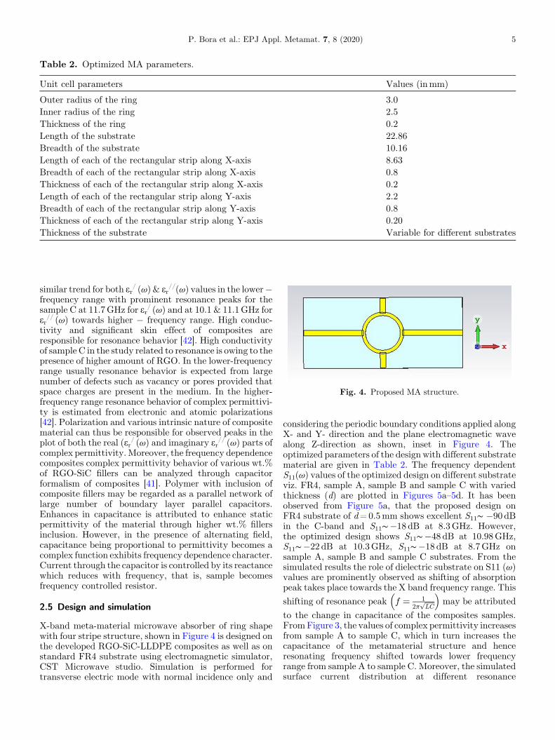
Fig. 4. Proposed MA structure.
Table 2. Optimized MA parameters.
Unit cell parameters Values (inmm)
Outer radius of the ring 3.0Inner radius of the ring 2.5Thickness of the ring 0.2Length of the substrate 22.86Breadth of the substrate 10.16Length of each of the rectangular strip along X-axis 8.63Breadth of each of the rectangular strip along X-axis 0.8Thickness of each of the rectangular strip along X-axis 0.2Length of each of the rectangular strip along Y-axis 2.2Breadth of each of the rectangular strip along Y-axis 0.8Thickness of each of the rectangular strip along Y-axis 0.20Thickness of the substrate Variable for different substrates
P. Bora et al.: EPJ Appl. Metamat. 7, 8 (2020) 5
similar trend for both er/ (v) & er
//(v) values in the lower�frequency range with prominent resonance peaks for thesample C at 11.7GHz for er
/ (v) and at 10.1 & 11.1GHz forer// (v) towards higher � frequency range. High conduc-
tivity and significant skin effect of composites areresponsible for resonance behavior [42]. High conductivityof sample C in the study related to resonance is owing to thepresence of higher amount of RGO. In the lower-frequencyrange usually resonance behavior is expected from largenumber of defects such as vacancy or pores provided thatspace charges are present in the medium. In the higher-frequency range resonance behavior of complex permittivi-ty is estimated from electronic and atomic polarizations[42]. Polarization and various intrinsic nature of compositematerial can thus be responsible for observed peaks in theplot of both the real (er
/ (v) and imaginary er// (v) parts of
complex permittivity.Moreover, the frequency dependencecomposites complex permittivity behavior of various wt.%of RGO-SiC fillers can be analyzed through capacitorformalism of composites [41]. Polymer with inclusion ofcomposite fillers may be regarded as a parallel network oflarge number of boundary layer parallel capacitors.Enhances in capacitance is attributed to enhance staticpermittivity of the material through higher wt.% fillersinclusion. However, in the presence of alternating field,capacitance being proportional to permittivity becomes acomplex function exhibits frequency dependence character.Current through the capacitor is controlled by its reactancewhich reduces with frequency, that is, sample becomesfrequency controlled resistor.
2.5 Design and simulation
X-band meta-material microwave absorber of ring shapewith four stripe structure, shown in Figure 4 is designed onthe developed RGO-SiC-LLDPE composites as well as onstandard FR4 substrate using electromagnetic simulator,CST Microwave studio. Simulation is performed fortransverse electric mode with normal incidence only and
considering the periodic boundary conditions applied alongX- and Y- direction and the plane electromagnetic wavealong Z-direction as shown, inset in Figure 4. Theoptimized parameters of the design with different substratematerial are given in Table 2. The frequency dependentS11(v) values of the optimized design on different substrateviz. FR4, sample A, sample B and sample C with variedthickness (d) are plotted in Figures 5a–5d. It has beenobserved from Figure 5a, that the proposed design onFR4 substrate of d=0.5mm shows excellent S11∼ �90 dBin the C-band and S11∼�18 dB at 8.3GHz. However,the optimized design shows S11∼�48 dB at 10.98GHz,S11∼�22 dB at 10.3GHz, S11∼�18 dB at 8.7GHz onsample A, sample B and sample C substrates. From thesimulated results the role of dielectric substrate on S11 (v)values are prominently observed as shifting of absorptionpeak takes place towards the X band frequency range. This
shifting of resonance peak f ¼ 12p
ffiffiffiffiffiLC
p� �
may be attributed
to the change in capacitance of the composites samples.FromFigure 3, the values of complex permittivity increasesfrom sample A to sample C, which in turn increases thecapacitance of the metamaterial structure and henceresonating frequency shifted towards lower frequencyrange from sample A to sample C. Moreover, the simulatedsurface current distribution at different resonance
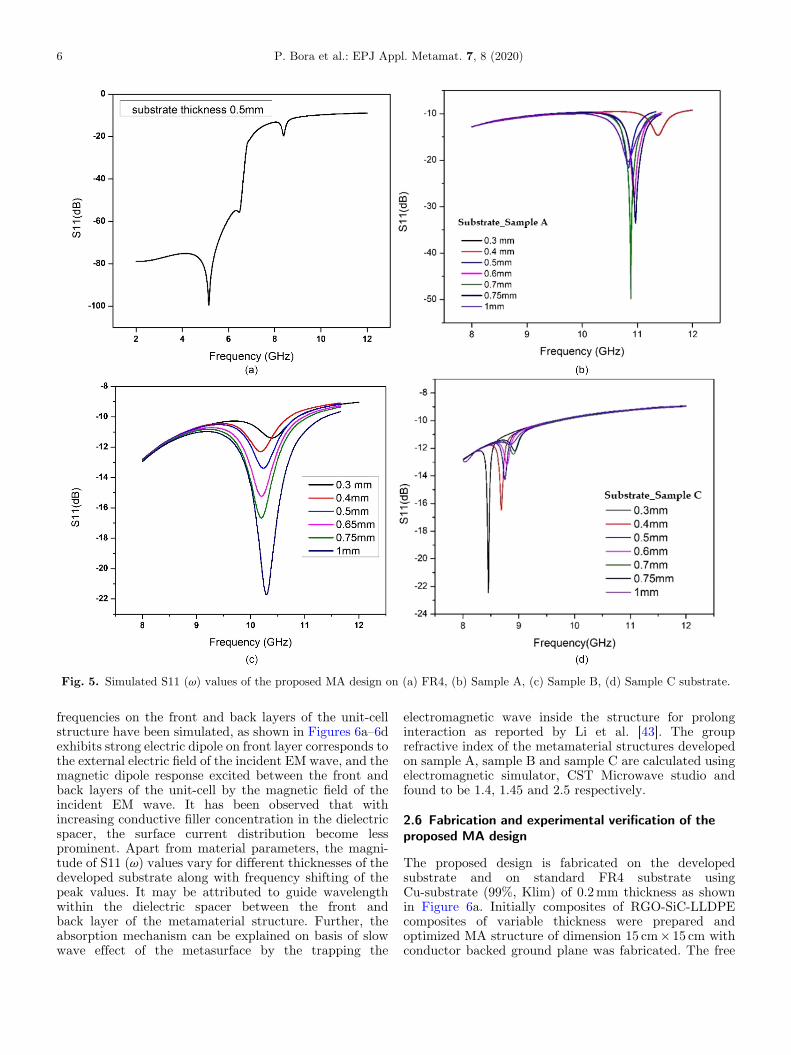
Fig. 5. Simulated S11 (v) values of the proposed MA design on (a) FR4, (b) Sample A, (c) Sample B, (d) Sample C substrate.
6 P. Bora et al.: EPJ Appl. Metamat. 7, 8 (2020)
frequencies on the front and back layers of the unit-cellstructure have been simulated, as shown in Figures 6a–6dexhibits strong electric dipole on front layer corresponds tothe external electric field of the incident EM wave, and themagnetic dipole response excited between the front andback layers of the unit-cell by the magnetic field of theincident EM wave. It has been observed that withincreasing conductive filler concentration in the dielectricspacer, the surface current distribution become lessprominent. Apart from material parameters, the magni-tude of S11 (v) values vary for different thicknesses of thedeveloped substrate along with frequency shifting of thepeak values. It may be attributed to guide wavelengthwithin the dielectric spacer between the front andback layer of the metamaterial structure. Further, theabsorption mechanism can be explained on basis of slowwave effect of the metasurface by the trapping the
electromagnetic wave inside the structure for prolonginteraction as reported by Li et al. [43]. The grouprefractive index of the metamaterial structures developedon sample A, sample B and sample C are calculated usingelectromagnetic simulator, CST Microwave studio andfound to be 1.4, 1.45 and 2.5 respectively.
2.6 Fabrication and experimental verification of theproposed MA design
The proposed design is fabricated on the developedsubstrate and on standard FR4 substrate usingCu-substrate (99%, Klim) of 0.2mm thickness as shownin Figure 6a. Initially composites of RGO-SiC-LLDPEcomposites of variable thickness were prepared andoptimized MA structure of dimension 15 cm� 15 cm withconductor backed ground plane was fabricated. The free
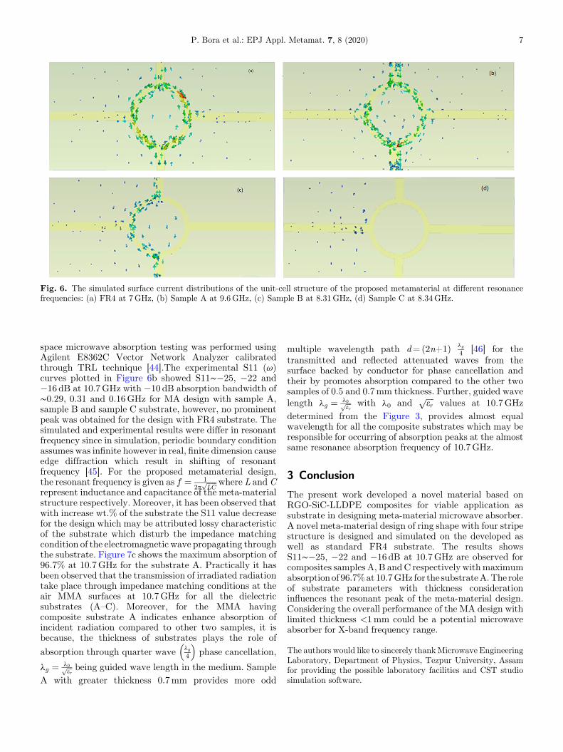
Fig. 6. The simulated surface current distributions of the unit-cell structure of the proposed metamaterial at different resonancefrequencies: (a) FR4 at 7GHz, (b) Sample A at 9.6GHz, (c) Sample B at 8.31GHz, (d) Sample C at 8.34GHz.
P. Bora et al.: EPJ Appl. Metamat. 7, 8 (2020) 7
space microwave absorption testing was performed usingAgilent E8362C Vector Network Analyzer calibratedthrough TRL technique [44].The experimental S11 (v)curves plotted in Figure 6b showed S11∼�25, �22 and�16 dB at 10.7GHz with �10 dB absorption bandwidth of∼0.29, 0.31 and 0.16GHz for MA design with sample A,sample B and sample C substrate, however, no prominentpeak was obtained for the design with FR4 substrate. Thesimulated and experimental results were differ in resonantfrequency since in simulation, periodic boundary conditionassumes was infinite however in real, finite dimension causeedge diffraction which result in shifting of resonantfrequency [45]. For the proposed metamaterial design,the resonant frequency is given as f ¼ 1
2pffiffiffiffiffiLC
p where L andCrepresent inductance and capacitance of the meta-materialstructure respectively. Moreover, it has been observed thatwith increase wt.% of the substrate the S11 value decreasefor the design which may be attributed lossy characteristicof the substrate which disturb the impedance matchingcondition of the electromagnetic wave propagating throughthe substrate. Figure 7c shows the maximum absorption of96.7% at 10.7GHz for the substrate A. Practically it hasbeen observed that the transmission of irradiated radiationtake place through impedance matching conditions at theair MMA surfaces at 10.7GHz for all the dielectricsubstrates (A–C). Moreover, for the MMA havingcomposite substrate A indicates enhance absorption ofincident radiation compared to other two samples, it isbecause, the thickness of substrates plays the role of
absorption through quarter wave lg4
� �phase cancellation,
lg ¼ l0ffiffiffier
p being guided wave length in the medium. SampleA with greater thickness 0.7mm provides more odd
multiple wavelength path d=(2n+1) lg4 [46] for the
transmitted and reflected attenuated waves from thesurface backed by conductor for phase cancellation andtheir by promotes absorption compared to the other twosamples of 0.5 and 0.7mm thickness. Further, guided wavelength lg ¼ l0ffiffiffi
erp with l0 and
ffiffiffiffier
pvalues at 10.7GHz
determined from the Figure 3, provides almost equalwavelength for all the composite substrates which may beresponsible for occurring of absorption peaks at the almostsame resonance absorption frequency of 10.7GHz.
3 Conclusion
The present work developed a novel material based onRGO-SiC-LLDPE composites for viable application assubstrate in designing meta-material microwave absorber.A novel meta-material design of ring shape with four stripestructure is designed and simulated on the developed aswell as standard FR4 substrate. The results showsS11∼�25, �22 and �16 dB at 10.7GHz are observed forcomposites samples A, B andC respectively withmaximumabsorptionof 96.7%at10.7GHz for the substrateA.The roleof substrate parameters with thickness considerationinfluences the resonant peak of the meta-material design.Considering the overall performance of the MA design withlimited thickness <1mm could be a potential microwaveabsorber for X-band frequency range.
The authors would like to sincerely thankMicrowave EngineeringLaboratory, Department of Physics, Tezpur University, Assamfor providing the possible laboratory facilities and CST studiosimulation software.
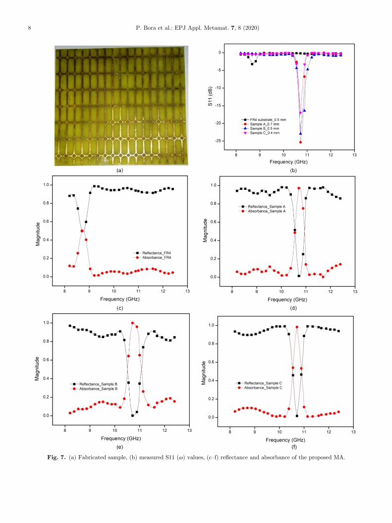
Fig. 7. (a) Fabricated sample, (b) measured S11 (v) values, (c–f) reflectance and absorbance of the proposed MA.
8 P. Bora et al.: EPJ Appl. Metamat. 7, 8 (2020)
P. Bora et al.: EPJ Appl. Metamat. 7, 8 (2020) 9
References
1. X.C. Tong, Advanced materials and design for electromag-netic interference shielding (CRC Press, Taylor and Francis,New York, 2009)
2. F. Qin, C. Brosseau, J. Appl. Phys. 111, 061301 (2012)3. C.M. Watts, X. Liu, W.J. Padilla, Adv. Mater. 24,
OP98 (2012)4. P.K. Singh, K.A. Korolev, M.N. Afsar, S. Sonkusale, Appl.
Phys. Lett. 99, 261101m (2011)5. N.I. Landy, S. Sajuyigbe, J.J. Mock, D.R. Smith, W.J.
Padilla, Phys. Rev. Lett. 100, 207402 (2008)6. B. Zhu, C. Huang, Y. Feng, J. Zhao, T. Jiang, Prog.
Electromagn. Res. B 24, 121 (2010)7. C.M. Bingham, H. Tao, X. Liu, R.D. Averitt, X. Zhang, W.J.
Padilla, Opt. Express 16, 18565 (2008)8. G.T. Ruck, D.E. Barrick, W.D. Stuart, Radar Cross Section
Handbook (Plenum, New York, 1970)9. J.W. Park, P.V. Tuong, J.Y. Rhee, K.W. Kim, W.H. Jang,
E.H. Choi, L.Y. Chen, Y.P. Lee, Opt. Express 21, 9691(2013)
10. Y.J. Yoo, Y.J. Kim, P.V. Tuong, J.Y. Rhee, K.W.Kim,W.H.Jang, Y.H. Kim, H. Cheong, Y.P. Lee, Opt. Express 21,32484 (2013)
11. F. Ding, Y. Cui, X. Ge, Y. Jin, S. He, Appl. Phys. Lett. 100,103506 (2012)
12. Y.J. Kim, Y.J. Yoo, K.W. Kim, J.Y. Rhee, Y.H. Kim, Y.P.Lee, Opt. Express 23, 3861 (2015)
13. Y.J. Kim et al., J. Phys. D Appl. Phys. 49, 435102 (2016)14. R. Pelluri, B. Appasani, Prog. Electromagn. Res. Lett. 69, 59
(2017)15. T.H. Nguyen et al., Adv. Nat. Sci. Nanosci. Nanotechnol. 5,
025013 (2014)16. R. Yahiaoui, H.H. Ouslimani, J. Appl. Phys. 122, 093104
(2017)17. T.S. Tuan, N.T.Q. Hoa, AIP Adv. 9, 055321 (2019)18. S. Bhattacharyya, S. Ghosh, K.V. Srivastava, J. Appl. Phys.
114, 094514 (2013)19. W. Wang, M. Yan, Y. Pang, J. Wang, H. Ma, S. Qua, H.
Chen, C. Xu, M. Feng, Appl. Phys. A 118, 443 (2015)20. W.G. Dong, L.M. Hai, H.X. Wei, K.L. Hua, C.L. Li, C.Z.
Quan, Chin. Phys. B 23, 017802 (2013)21. L. Li, Y. Yang, C. Liang, J. Appl. Phys. 110, 063702 (2011)22. O. Ayop, M.K.A. Rahim, N.A. Murad, H.A. Majid, Appl.
Phys. A 117, 651 (2014)
23. R. Pelluri, B. Appasani, Prog. Electromagn. Res. Lett. 69, 59(2017)
24. B.S. Tung, B.X. Khuyen, Y.J. Kim, V.D. Lam, K.W. Kim,Y.P. Lee, Sci. Rep. 7, 11507 (2017)
25. G. Sen, M. Kumar, S.k.N. Islam, S. Das, Wave RandomComplex Media 29, 153 (2019)
26. D. Sood, C.C. Tripathi, J. Microwave, Optoelectron.Electromagn. Appl. 16, 514 (2017)
27. K. Kumari, N. Mishra, R.K. Chaudhary, Microw. Opt.Technol. Lett. 59, 2664 (2017)
28. D. Borah, N.S. Bhattacharyya, J. Electron. Mater. 46,226 (2017)
29. C. Wang, X. Han, P. Xu, X. Zhang, Y. Du, Appl. Phys. Lett.98, 072906 (2011)
30. H.J. Yang, J. Yuan, Y. Li, Z.L. Hou, H.B. Jin, X.Y. Fang,M.S. Cao, Solid State Commun. 163, 1 (2013)
31. W.S. Hummers, R.E. Offeman, J. Am. Chem. Soc. 80, 1339(1958)
32. N. Cao, Y. Zhang, J. Nanomater. 2015, 168125 (2015)33. P.J. Gogoi, S. Bhattacharyya, N.S. Bhattacharyya, J.
Electron. Mater. 44, 1071 (2015)34. D.Y. Pan, S. Wang, B. Zhao, M.H. Wu, H.J. Zhang, Y.
Wang, Z. Jiao, Chem. Mater. 21, 3136 (2009)35. A.L. Ortiz, F. Sanchez-Bajo, F.L. Cumbrera, F. Guiberteau,
Mater. Lett. 49, 137 (2001)36. S. Sunderrajan, L.R.Miranda, G. Pennathur, Prep. Biochem.
Biotechnol. 48, 343 (2018)37. A.M. Nicolson, G. Ross, IEEE Trans. Instrum. Meas. 19, 377
(1970)38. Y. Zhang, S. Gao, H. Xing, J. Alloy. Compd. 777, 544 (2019)39. X.F. Zhang, P.F. Guan, X.L. Dong, Appl. Phys. Lett. 96,
223111 (2010)40. U.J Mahanta, J.P Gogoi, D. Borah, N.S. Bhattacharyya,
IEEE Trans. Dielectr. Electr. Insul. 26, 194 (2019)41. U.J. Mahanta, N.S. Bhattacharyya, I. Hussain, P.J. Gogoi,
J.P. Gogoi, J. Phys. Chem. Solids 127, 202 (2019)42. Y. Li, R. Wang, F. Qi, C. Wang, Appl. Surf. Sci. 254, 4708
(2008)43. Z. Li, B. Li, Q. Zhao, J. Zhou, AIP Adv. 10, 045311 (2020)44. G.F. Engen, C.A. Hoer, IEEE. Trans. Microw. Theory Tech.
27, 987 (1979)45. X. Huang, H. Yang, S. Yu, J. Wang, M. Li, Q. Ye, J. Appl.
Phys. 113, 213516 (2013)46. L. Zhang, H. Zhu, Y. Song, Y. Zhang, Y. Huang, Mater. Sci.
Eng. B 153, 78 (2008)
Cite this article as: Pankaj Bora, Utpal Jyoti Mahanta, Jayanta Kumar Sarmah, Jyoti Prasad Gogoi, X-band metamaterialabsorbers based on reduced graphene oxide-silicon carbide-linear low density polyethylene composite, EPJ Appl. Metamat. 7, 8(2020)


![Review Article A Review of Computational Electromagnetic ...et al. [ ] used metamaterial made up of periodic graphene microribbon arrays for terahertz plasmon excitations and demonstrated](https://img.pdfslide.us/doc/110x75/60bf77d5262f570c1e13764b/review-article-a-review-of-computational-electromagnetic-et-al-used-metamaterial.jpg)