Embed Size (px)
Citation preview
WP white paper
Guidelines for Meeting IEC 60730 Class B Requirements with FM3 MCUsSelf-Test Library Implementations
2
ContentsO
1. Introduction .....................................................................................................................................3
Fujitsu FM3 Microcontrollers and Code Library ....................................................................................3
2. IEC 60730 Self-Test Library Structure ................................................................................................3
2.2. Self-Test Library: Structure of Test Routines ..................................................................................4
2.2.1 CPU Test and Fow Chart ...........................................................................................................4
2.2.2 CPU Register Test ....................................................................................................................4
2.2.3 Clock Tests ..............................................................................................................................5
2.2.4. Interrupt Test .........................................................................................................................6
2.2.5. ROM/Flash checksum integrity check .....................................................................................6
2.2.6. RAM Test (using checkerboard) and Flow Chart ......................................................................8
2.2.7. IO Peripheral Tests .................................................................................................................8
3.3. Fujitsu Self-Test Library Deliverables: ...........................................................................................9
3. Conclusion .....................................................................................................................................10
3
1. IntroductionOFujitsu ARM Cortex – FM3 family microcontrollers (MCUs) offer a variety of integrated functional safety features that suit home appliances, white goods and other motor-control applications. Fujitsu also provides an extensive library of safety-related software routines to make these features easier to use. Because these software routines are compliant with International Electro-Technical Commission (IEC) safety standards, using the routines greatly simplifies IEC certification for the final product.
This application note gives an overview of the use of Fujitsu FM3 microcontrollers and code libraries to comply with the standards. The focus of this paper is on the library of self-test routines that address IEC 60730 Class B requirements.
Fujitsu FM3 Microcontrollers and Code LibraryAll the members of Fujitsu’s wide-ranging MCU family incorporate standard ARM CPU core, tools and features, so future programming can build on a steady foundation. By using the de facto industry standard ARM core, Fujitsu offers easier migration of code across product lines and from one product generation to the next.
The high-performance 32-bit architecture of Fujitsu’s ARM Cortex microcontrollers provides the computational power necessary for high-energy-efficiency motor control, while the devices also offer a versatile range of on-chip peripherals. The FM3 family includes Basic, High-Performance and Low-Leakage groups of MCUs that are well suited to applications such as air conditioners, washing machines, induction cookers and refrigerator compressors.
Supporting these hardware enhancements is a new version of the FM3 firmware library — pre-coded digital power and motor-specific algorithms available free from Fujitsu. The Fujitsu library minimizes code development time and provides a way to immediately use the MCU’s on-chip safety features rather than expensive external devices. The library supports assembly and C mixed coding on IAR and Keil Compiler IDE platforms.
2. IEC 60730 Self-Test Library StructureOThe Fujitsu self-test library (STL) for the 32-bit ARM Cortex – FM3 Family covers IEC 60730 and IEC60335 requirements. These libraries use a standard application programming interface (API) between the system hardware and the application software.
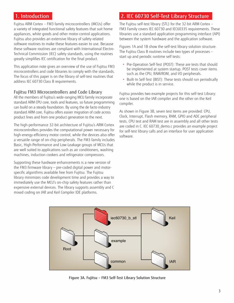
Figures 1A and 1B show the self-test library solution structure. The Fujitsu Class B routines include two types of processes — start up and periodic runtime self tests:
• Pre-Operation Self-Test (POST): These are tests that should be implemented at system startup. POST tests cover items such as the CPU, RAM/ROM, and I/O peripherals.
• Built-In Self-Test (BIST): These tests should run periodically while the product is in service.
Fujitsu provides two example projects for this self-test Library: one is based on the IAR compiler and the other on the Keil compiler.
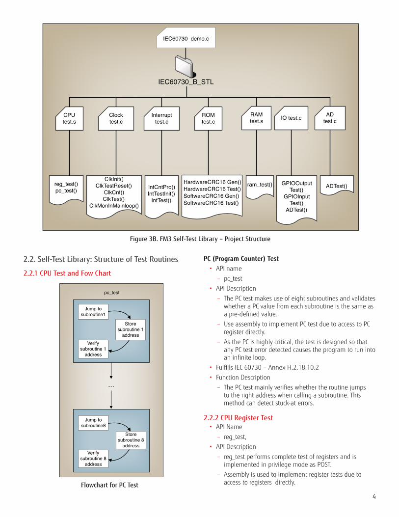
As shown in Figure 3B, seven test items are provided: CPU, Clock, Interrupt, Flash memory, RAM, GPIO and ADC peripheral tests. CPU test and RAM test are in assembly and all other tests are coded in C. IEC 60730_demo.c provides an example project for self-test library calls and an interface for user application software.
iec60730_b_stl
IAR
Keil
Root
example
common
Figure 3A. Fujitsu – FM3 Self-Test Library Solution Structure
4
2.2. Self-Test Library: Structure of Test Routines
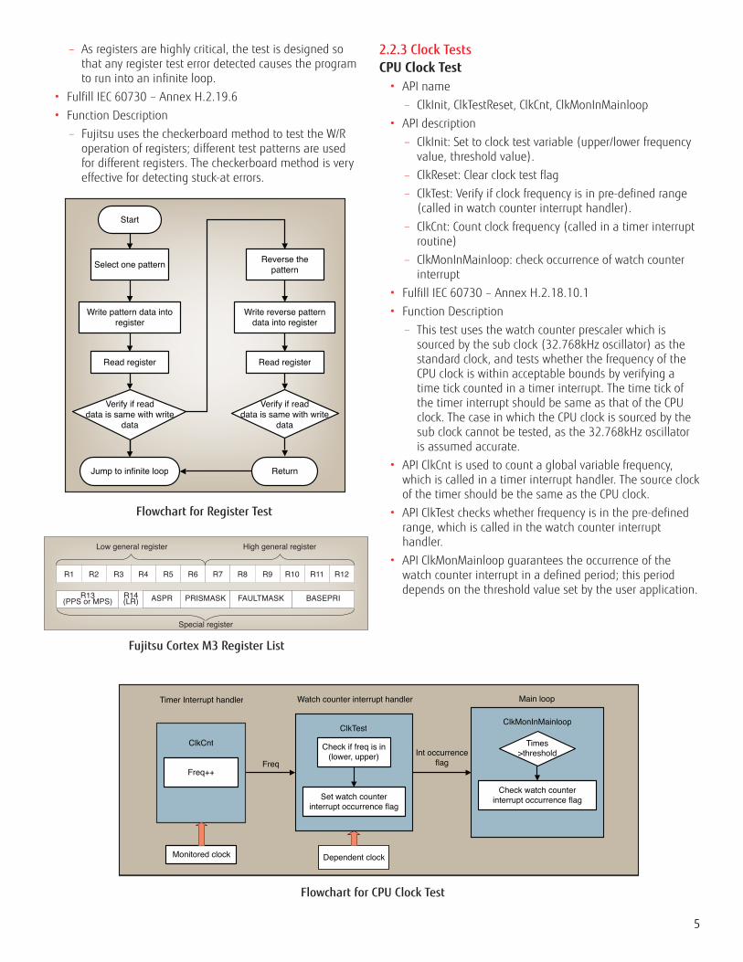
2.2.1 CPU Test and Fow Chart
Flowchart for PC Test
PC (Program Counter) Test• API name
– pc_test
• API Description
– The PC test makes use of eight subroutines and validates whether a PC value from each subroutine is the same as a pre-defined value.
– Use assembly to implement PC test due to access to PC register directly.
– As the PC is highly critical, the test is designed so that any PC test error detected causes the program to run into an infinite loop.
• Fulfills IEC 60730 – Annex H.2.18.10.2
• Function Description
– The PC test mainly verifies whether the routine jumps to the right address when calling a subroutine. This method can detect stuck-at errors.
2.2.2 CPU Register Test• API Name
– reg_test,
• API Description
– reg_test performs complete test of registers and is implemented in privilege mode as POST.
– Assembly is used to implement register tests due to access to registers directly.
IEC60730_B_STL
CPU test.s
Clock test.c
Interrupt test.c
RAM test.s
ROM test.c IO test.c
reg_test()pc_test()
ClkInit()ClkTestReset()
ClkCnt()ClkTest()
ClkMonInMainloop()
IntCntPro()IntTestInit()
IntTest()
HardwareCRC16 Gen()HardwareCRC16 Test()SoftwareCRC16 Gen()SoftwareCRC16 Test()
ram_test() GPIOOutputTest()
GPIOInputTest()
ADTest()
AD test.c
ADTest()
IEC60730_demo.c
Figure 3B. FM3 Self-Test Library – Project Structure
Jump to subroutine1
Store subroutine 1
addressVerify
subroutine 1 address
...
Jump to subroutine8
Store subroutine 8
addressVerify
subroutine 8 address
pc_test
5
– As registers are highly critical, the test is designed so that any register test error detected causes the program to run into an infinite loop.
• Fulfill IEC 60730 – Annex H.2.19.6
• Function Description
– Fujitsu uses the checkerboard method to test the W/R operation of registers; different test patterns are used for different registers. The checkerboard method is very effective for detecting stuck-at errors.
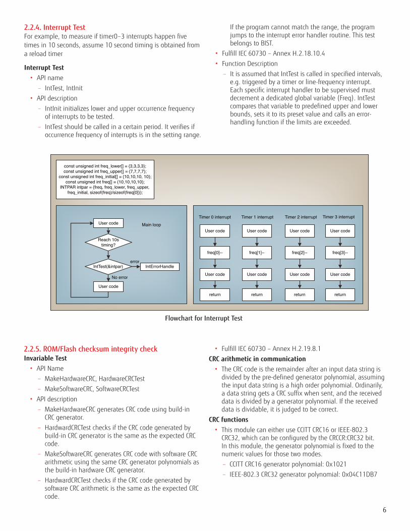
Flowchart for Register Test
2.2.3 Clock TestsCPU Clock Test• API name
– ClkInit, ClkTestReset, ClkCnt, ClkMonInMainloop
• API description
– ClkInit: Set to clock test variable (upper/lower frequency value, threshold value).
– ClkReset: Clear clock test flag
– ClkTest: Verify if clock frequency is in pre-defined range (called in watch counter interrupt handler).
– ClkCnt: Count clock frequency (called in a timer interrupt routine)
– ClkMonInMainloop: check occurrence of watch counter interrupt
• Fulfill IEC 60730 – Annex H.2.18.10.1
• Function Description
– This test uses the watch counter prescaler which is sourced by the sub clock (32.768kHz oscillator) as the standard clock, and tests whether the frequency of the CPU clock is within acceptable bounds by verifying a time tick counted in a timer interrupt. The time tick of the timer interrupt should be same as that of the CPU clock. The case in which the CPU clock is sourced by the sub clock cannot be tested, as the 32.768kHz oscillator is assumed accurate.
• API ClkCnt is used to count a global variable frequency, which is called in a timer interrupt handler. The source clock of the timer should be the same as the CPU clock.
• API ClkTest checks whether frequency is in the pre-defined range, which is called in the watch counter interrupt handler.
• API ClkMonMainloop guarantees the occurrence of the watch counter interrupt in a defined period; this period depends on the threshold value set by the user application.
Select one pattern
Write pattern data into register
Read register
Verify if read data is same with write
data
Start
Jump to infinite loop
Reverse the pattern
Write reverse pattern data into register
Read register
Verify if read data is same with write
data
Return
R1
R13(PPS or MPS)
R14(LR) ASPR PRISMASK
Low general register
Special register
High general register
FAULTMASK BASEPRI
R2 R3 R4 R9 R10 R11 R12R5 R6 R7 R8
Fujitsu Cortex M3 Register List
Freq++
ClkCnt
Set watch counter interrupt occurrence flag
ClkTest
Check watch counter interrupt occurrence flag
ClkMonInMainloop
FreqInt occurrence
flag
Timer Interrupt handler Watch counter interrupt handler Main loop
Monitored clock Dependent clock
Check if freq is in (lower, upper)
Times >threshold
Flowchart for CPU Clock Test
6
2.2.4. Interrupt TestFor example, to measure if timer0–3 interrupts happen five times in 10 seconds, assume 10 second timing is obtained from a reload timer
Interrupt Test• API name
– IntTest, IntInit
• API description
– IntInit initializes lower and upper occurrence frequency of interrupts to be tested.
– IntTest should be called in a certain period. It verifies if occurrence frequency of interrupts is in the setting range.
If the program cannot match the range, the program jumps to the interrupt error handler routine. This test belongs to BIST.
• Fulfill IEC 60730 – Annex H.2.18.10.4
• Function Description
– It is assumed that IntTest is called in specified intervals, e.g. triggered by a timer or line-frequency interrupt. Each specific interrupt handler to be supervised must decrement a dedicated global variable (Freq). IntTest compares that variable to predefined upper and lower bounds, sets it to its preset value and calls an error-handling function if the limits are exceeded.
Flowchart for Interrupt Test
const unsigned int freq_lower[] = {3,3,3,3};const unsigned int freq_upper[] = {7,7,7,7};
const unsigned int freq_initial[] = {10,10,10, 10};const unsigned int freq[] = {10,10,10,10};
INTPAR intpar = {freq, freq_lower, freq_upper, freq_initial, sizeof(freq)/sizeof(freq[0])};
User code
Reach 10s timing?
User code
IntErrorHandle
freq[0]-- freq[1]-- freq[2]-- freq[3]--
User code User code User code User code
User code User code User code User code
error
No error
Main loopTimer 0 interrupt Timer 1 interrupt Timer 2 interrupt
return return return return
Timer 3 interrupt
IntTest(&intpar)
2.2.5. ROM/Flash checksum integrity checkInvariable Test• API Name
– MakeHardwareCRC, HardwareCRCTest
– MakeSoftwareCRC, SoftwareCRCTest
• API description
– MakeHardwareCRC generates CRC code using build-in CRC generator.
– HardwardCRCTest checks if the CRC code generated by build-in CRC generator is the same as the expected CRC code.
– MakeSoftwareCRC generates CRC code with software CRC arithmetic using the same CRC generator polynomials as the build-in hardware CRC generator.
– HardwardCRCTest checks if the CRC code generated by software CRC arithmetic is the same as the expected CRC code.
• Fulfill IEC 60730 – Annex H.2.19.8.1
CRC arithmetic in communication • The CRC code is the remainder after an input data string is
divided by the pre-defined generator polynomial, assuming the input data string is a high order polynomial. Ordinarily, a data string gets a CRC suffix when sent, and the received data is divided by a generator polynomial. If the received data is dividable, it is judged to be correct.
CRC functions• This module can either use CCITT CRC16 or IEEE-802.3
CRC32, which can be configured by the CRCCR:CRC32 bit. In this module, the generator polynomial is fixed to the numeric values for those two modes.
– CCITT CRC16 generator polynomial: 0x1021
– IEEE-802.3 CRC32 generator polynomial: 0x04C11DB7
7
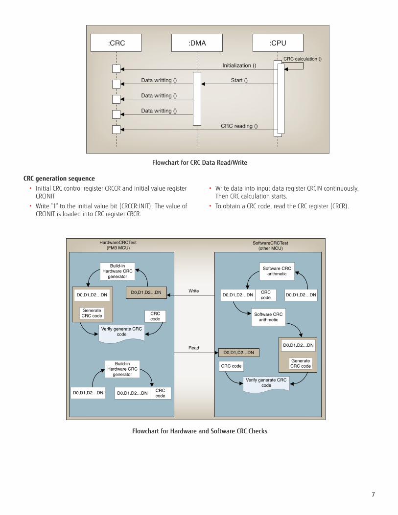
CRC generation sequence • Initial CRC control register CRCCR and initial value register
CRCINIT
• Write “1” to the initial value bit (CRCCR:INIT). The value of CRCINIT is loaded into CRC register CRCR.
• Write data into input data register CRCIN continuously. Then CRC calculation starts.
• To obtain a CRC code, read the CRC register (CRCR).
Build-in Hardware CRC
generator
D0,D1,D2…DN D0,D1,D2…DN
CRC code
Software CRC arithmetic
D0,D1,D2…DND0,D1,D2…DN CRC code
Generate CRC code
Verify generate CRC code
Build-in Hardware CRC
generator
D0,D1,D2…DN D0,D1,D2…DN CRC code
Write
D0,D1,D2…DND0,D1,D2…DN
CRC codeGenerate CRC code
Verify generate CRC code
Software CRC arithmetic
Read
HardwareCRCTest (FM3 MCU)
SoftwareCRCTest(other MCU)
Flowchart for Hardware and Software CRC Checks
:CRC
Data writting ()
Data writting ()
Data writting ()
CRC reading ()
Start ()
Initialization ()CRC calculation ()
:DMA :CPU
Flowchart for CRC Data Read/Write
8
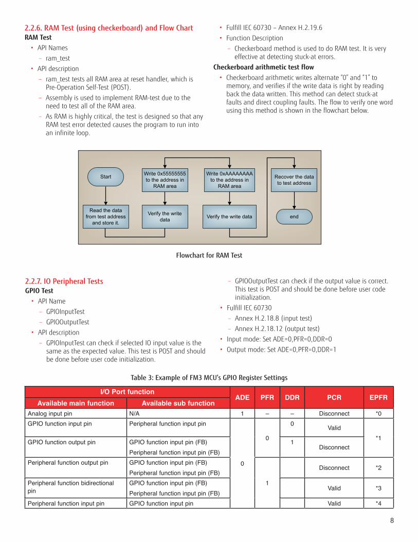
2.2.6. RAM Test (using checkerboard) and Flow ChartRAM Test• API Names
– ram_test
• API description
– ram_test tests all RAM area at reset handler, which is Pre-Operation Self-Test (POST).
– Assembly is used to implement RAM-test due to the need to test all of the RAM area.
– As RAM is highly critical, the test is designed so that any RAM test error detected causes the program to run into an infinite loop.
• Fulfill IEC 60730 – Annex H.2.19.6
• Function Description
– Checkerboard method is used to do RAM test. It is very effective at detecting stuck-at errors.
Checkerboard arithmetic test flow• Checkerboard arithmetic writes alternate “0” and “1” to
memory, and verifies if the write data is right by reading back the data written. This method can detect stuck-at faults and direct coupling faults. The flow to verify one word using this method is shown in the flowchart below.
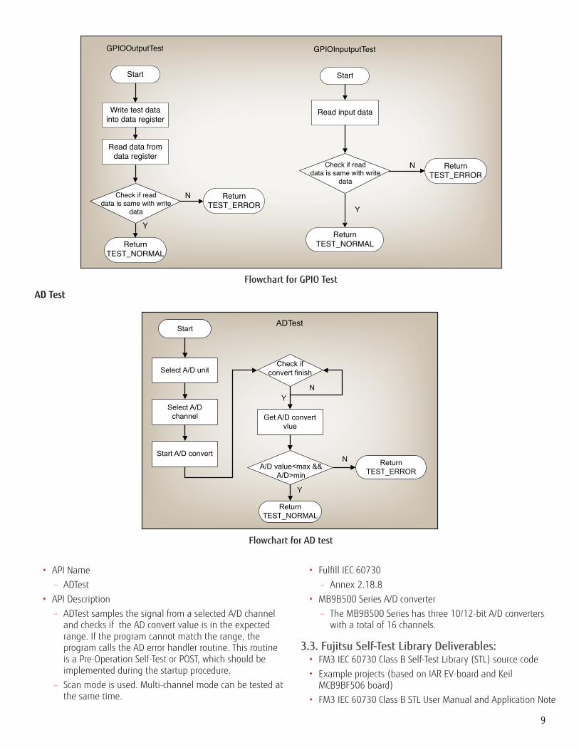
2.2.7. IO Peripheral TestsGPIO Test• API Name
– GPIOInputTest
– GPIOOutputTest
• API description
– GPIOInputTest can check if selected IO input value is the same as the expected value. This test is POST and should be done before user code initialization.
– GPIOOutputTest can check if the output value is correct. This test is POST and should be done before user code initialization.
• Fulfill IEC 60730
– Annex H.2.18.8 (input test)
– Annex H.2.18.12 (output test)
• Input mode: Set ADE=0,PFR=0,DDR=0
• Output mode: Set ADE=0,PFR=0,DDR=1
Flowchart for RAM Test
Start Write 0x55555555 to the address in
RAM area
Verify the write data
Write 0xAAAAAAAA to the address in
RAM area
Read the data from test address
and store it. Verify the write data
Recover the data to test address
end
I/O Port functionADE PFR DDR PCR EPFR
Available main function Available sub functionAnalog input pin N/A 1 – – Disconnect *0GPIO function input pin Peripheral function input pin
0
0
0 Valid*1GPIO function output pin GPIO function input pin (FB)
Peripheral function input pin (FB)1
Disconnect
Peripheral function output pin GPIO function input pin (FB)Peripheral function input pin (FB)
1
Disconnect *2
Peripheral function bidirectional pin
GPIO function input pin (FB)Peripheral function input pin (FB)
Valid *3
Peripheral function input pin GPIO function input pin Valid *4
Table 3: Example of FM3 MCU’s GPIO Register Settings
9
Start
Write test data into data register
Read data from data register
Return TEST_NORMAL
Return TEST_ERROR
N
GPIOOutputTest
Y
Read input data
ReturnTEST_NORMAL
ReturnTEST_ERROR
Y
N
Start
GPIOInputputTest
Check if read data is same with write
data
Check if read data is same with write
data
Flowchart for GPIO Test
Start
Select A/D unit
Select A/D channel
Start A/D convert
Check if convert finish
Get A/D convert vlue
ReturnTEST_NORMAL
Return TEST_ERROR
YN
Y
N
ADTest
A/D value<max &&A/D>min
Flowchart for AD test
AD Test
• API Name
– ADTest
• API Description
– ADTest samples the signal from a selected A/D channel and checks if the AD convert value is in the expected range. If the program cannot match the range, the program calls the AD error handler routine. This routine is a Pre-Operation Self-Test or POST, which should be implemented during the startup procedure.
– Scan mode is used. Multi-channel mode can be tested at the same time.
• Fulfill IEC 60730
– Annex 2.18.8
• MB9B500 Series A/D converter
– The MB9B500 Series has three 10/12-bit A/D converters with a total of 16 channels.
3.3. Fujitsu Self-Test Library Deliverables:• FM3 IEC 60730 Class B Self-Test Library (STL) source code
• Example projects (based on IAR EV-board and Keil MCB9BF506 board)
• FM3 IEC 60730 Class B STL User Manual and Application Note
3. ConclusionOThe introduction of IEC/UL 60730 into the design of white goods and other appliances will add a new level of safety for consumers. By taking advantage of Fujitsu’s FM3 Family MCUs, design teams can comply with the regulations while maintaining or reducing electronic system cost. Use of these MCUs and the Self-Test Library enables teams to create a strong system-level development platform and achieve superior performance, fast time to market and energy efficiency.
FUjITSU SEMICONDUCTOR AMERICA, INC.Corporate Headquarters1250 E. Arques Avenue, M/S 333, Sunnyvale, CA 94085-5401Tel: (800) 866-8608 Fax: (408) 737-5999E-mail: [email protected] | Website: http://us.fujitsu.com/semi
8
©2011 Fujitsu Semiconductor America, Inc.All company and product names are trademarks or registered trademarks of their respective owners.
Printed in the U.S.A. MCU-WP-21400-04/2011


![Atmel AVR1610: Guide to IEC 60730 Class B …ww1.microchip.com/downloads/en/AppNotes/doc42008.pdfAtmel AVR1610: Guide to IEC 60730 Class B Compliance with XMEGA [APPLICATION NOTE]](https://img.pdfslide.us/doc/110x75/5abf9f6d7f8b9add5f8deb78/atmel-avr1610-guide-to-iec-60730-class-b-ww1-avr1610-guide-to-iec-60730-class.jpg)