Embed Size (px)
Citation preview
OD-2045 Ed 1.02.0 20171-0112-18
Except for IECEE members and mandated persons, no part of this publication may be reproduced or utilized in any form or by any means, electronic or mechanical, including photocopying and microfilm, without permission in writing from the publisher IECEE Secretariat, 3, rue de Varembé, Geneva, Switzerland, Telefax : +41 22 919 0300, e-mail : [email protected]
IECEE OD-2045 Ed. 12.0
OPERATIONAL & RULING DOCUMENTS
Guideline Document & Work Instruction for testing purposes on how to
implement the Annex R of IEC 60335-1 and
Annex H of IEC 60730-1
IEC System for Conformity Testing and Certification of Electrotechnical equipment and Components
OD-2045 Ed 1.02.0 2/33 20171-0112-18
CONTENTS
Introduction .................................................................................................................................. 4 1. Objectives of this Guide ............................................................................................................... 5 2. Procedure for identification of clauses of IEC 60335 to be considered ......................................... 6 3. General procedure to detect and identify the software that requires special measures ................ 7 4. Addendum to the TRF’s of IEC 60335 series to include the minimum information required to 5.
identify the safety requirements applicable to the software and hardware. .......................................... 8 Examples for the software detection and identification ............................................................... 10 6. Process of Audit Trail, Items & Evaluation for Data Exchange Among NCB’s and CBTL’s ......... 17 7. Process to identify the SW and the way to reflect it in the TRF .................................................. 20 8. Process of audit and evaluation of the SW allows to fulfils the Table R1 or R2 .......................... 23 9.
Process to evaluate the software related safety independently of functional software and the 10.way to proceed when changes are done on it. .................................................................................. 32

IEC System for Conformity Testing and Certification of Electrotechnical equipment and Components
OD-2045 Ed 1.02.0 3/33 20171-0112-18
FOREWORD
Document Owner
CTL WG 5 “SOFTWARE EVALUATION”
History of changes
Revision Date Brief summary of changes
2017-12-18 Updated version including A1 and A2 of IEC 60335-1 5ªed and some interpretations from MT23 and IEC TC61
2011-01-18 Initial version
Effective date Target revision Next maintenance due date 2018-06-05 2021-06-05
IEC System for Conformity Testing and Certification of Electrotechnical equipment and Components
OD-2045 Ed 1.02.0 4/33 20171-0112-18
Introduction 1.
The use of electronic controls in appliances covered by IEC 60335 series promotedimplies important modifications in the standard to cover the safety aspects that reflects the differentiationsdifference between the requirements to be applied to the electromechanical and electronic controls in appliances require. An obvious difference is in the operation and construction of an electronic control. in comparison with an electromechanical control. The electromechanical components have only physical elements which, for example, are movable contacts to open or close a circuit, or may have a static response to electric signals, which change the circuit operation. ItsNormally the reliability of an electromechanical control can be evaluated by endurance tests, normally according to specific component standards, as it is reflected in Clause 24 of IEC 60335. In an electronic componentcontrol there is a hardware construction done with discrete electronic components and usually has a software to controlmanage the operation of the component. control. Even if the construction and principles of operation are different, the component standards can include thea way to evaluate the control operation reliability of the electronic control operation in the same way that does thatapplies for electromechanical components. But if the electronic control operates in an appliance, this is only possible only when the electronic control is clearly classified eitherused for a specific discrete function (timer, thermostat, switch, etc) and if it has a separate and clearly defined role for functional or afor protection purposes (i.e thermostat, or thermal cut-out).
The main problem for considering the component standard During the evaluation enough for of the compliance of appliances with IEC 60335 requirements some problems were identified with electronic controls integrated into an appliance. Using the same approach as for electromechanical controls during the safety assessment of the appliance is related with the fact that the appliance, it can be shown that the evaluation of the control according to its component standard may not be sufficient: - The electronic control usually integrate many functions and protections needed for the appliance
and it iswhich are not always easy to separate inidentify with the control the discreteindividual components that performor parts of the control performing the different tasks that are the base ofin relation with the safety analysis of the appliance, either in normal operation (Cl 11), or abnormal conditions (Cl 19). .
- By other hand, dependingDepending on the construction and functions of the appliance in which
it is integrated, the same electronic control may provide a normal operationoperating function in one of them and protectionappliance, or provide a protective function in other similar appliance, or even both functions in abnormalanother appliance.
- Cl 19 of IEC60335 and other clauses (i.e Cl 20, Cl 22, Cl 24) in Part 2’s require an specific evaluation and tests when the appliance incorporate electronic parts and controls. The compliance of these tests strongly depends on the construction and functionality of the appliance with its input and output signals. An electronic control tested separately (e.g. on a workbench), can not properly cover these conditions unless the inputs and outputs signals in the electronic circuit are simulated or evaluated in the same way that these signals are present in the real appliance under the same conditions in other, or even both of the.
- The above functions in a third appliance constructionhas an additional challenge in the case of 19.11.4, electromagnetic phenomena tests (EMP tests), in which the appliance physical construction (enclosure, wiring distribution, earthing and grounding, connection to the supply, filters, etc) clearly affect to the coupling of EMP signals in the appliance circuits and consequently on the inputs and outputs signals on the electronic circuits in addition to those direct effect on the electronic construction itself.
IEC System for Conformity Testing and Certification of Electrotechnical equipment and Components
OD-2045 Ed 1.02.0 5/33 20171-0112-18
For that reason it is necessary to perform an analysis of the electronic control and its functionality in each appliance an analysis of the electronic control and its functionality infor each of the conditions of the test requirement ofrequired in IEC 60335. This analysis is the previousfirst step to determine the requirements to be assigned to the control. and its functions. The analysis consequently will determine the test to be performed in the whole appliance according to clauseClauses 19, 20, 22, 24 etc, considering the different conditions applicable to the functional controls and protectionprotective parts or controls.
ByOn the other hand, thea previous analysis may reduce the tests to be performed because sometimes the control, or a part of it, provides the same appliance protection in more than one of the test of Cl 19.required and there is no need to repeat the same test in the same appliance. In other cases the reduction of, the same functions in similar appliances with the same construction may reduce the tests is, due to the consideration that the control plays the same role and then some of them are onlytest applicable to PECPEC’s (protective electronic circuits) and not to functional electronic circuits. Consequently for that purpose it is necessary to perform the analysis before starting thecould be covered in another tests. already done in other appliance.
Finally, in the same way that an analysis is necessary for the identification of the parts of the control that performs the safety functions, the test report shall include this information for certification traceability purposes. Consequently it is necessary to specify the tables, list of documents and the list of the relevant control parts, to be added to TRF.
With these objectives and according the conclusions of the CTL Software Workshops held in 2009 and 2010, the following rules for certification traceability, under IECEE system, applies:
As NCB A. Issuing the TR. Additional information to provide:
The part of the hardware that actuate in each test (table Cl 19) The part of the software that actuate in each test (table Cl 19) The different versions of the software that may be covered in the analysis. The reference of the documents that are used in the software evaluation to comply with the
Annex R list of measures. The identification code for the software
As NCB B. Using the TR issued by NCB A. What information to require:
Complete TR with the information proposed previously and clear identification of the hardware and software controls covered in the TR that will be used in the new application.
General drawings, samples marked with the control identification, software identification, or any other relevant document necessary, in order to check the traceability of the hardware and software, but not the software documents evaluated by NCB A.
Objectives of this Guide 2.TheWith the above considerations, the main objectives of this Guide are the following:
a) Procedure for identification of clauses of IEC 60335 to be considered in electronic controls using software for safety purposes.
b) General procedures to detect and identify the software that require special measures to control fault/error conditions specified in table R of IEC 60335.
c) Documents and information to be provided for the relevant audit of the SW measures and the way in which this documentation is identified in the TRF.
d) The way to identify the SW and the way to reflect it in the TRF including the versions and modifications of it.
e) The way in which the process of audit and evaluation of the SW allows to fulfils the Table R1 or R2.
IEC System for Conformity Testing and Certification of Electrotechnical equipment and Components
OD-2045 Ed 1.02.0 6/33 20171-0112-18
f) Addendum to the TRF’s of IEC 60335 series to include the minimum information required to identify the safety requirements applicable to the software and hardware.
g) Examples for the application of this guideline.
Procedure for identification of clauses of IEC 60335 to be considered 3.In IEC 60335-1 ed 4.2 software measures are only required for PEC’s, which according the definition in 3.9.3 are those electronic controls that prevent hazardous situation under abnormal operation conditions. In IEC 60335-1 Ed 5.2, protective electronic circuits (PEC´s) are referred only to Cl 19 compliance, but additionally protective SW and/or HW failures may be requested in some Part 2´s in some clauses (Cl 20, Cl 22, Cl 24 and others). For all of these conditions the procedure described in this guide is still applicable, but considering that the tests do not necessary include the same test sequence in all clauses. Considering that Cl 19 represents the test specifications that coversCl 19 of IEC 60335 cover the abnormal operation conditions, only during the test of this clause the electronic circuit need to be analysed, but it shall be noted that even if there are and irrespective of specific sub-clauses (19.11.1 and 19.11.2) for testing hardware failures on electronic components, all Cl 19 sub clauses appliestests still apply to check the electronic circuits whenif operate on these tests. Consequently any electronic circuit that needs to operate to ensure the compliance during the correspondingany Cl 19 sub-clause tests. became a PEC. ItOn the other hand, it is necessary to consider the difference between the testtests in Cl 19.11.2 and the other 19 sub-clauses. tests in other Cl 19 sub-clauses. During the analysis of an electronic control, it shall be noted that there is a difference between short-circuiting an electronic control compared to short-circuiting an electronic component of the control as required by Cl 19.11.2. When a 19 sub-clause (, other than 19.11.2, but including 19.10X in Part’sof any Part 2), requires to faila failure in a control that operateactuate in normal operation conditions, for a specific function (i.e thermostat, timer, pressure relief, etc), it shall be considered that the control shall be short-circuited, or rendered inoperative as a whole (note 5 of(Cl 19.1). When doing an analysis of an electronic control, it shall ), only for the correspondent function to be noted that it is differentchecked in the test and not to short-circuit the control than to short-circuitwhole electronic componentscontrol. Sometimes is not easy to render inoperative a function in a control, keeping operative other functions and protections of this control and the controlway in which is covered by 19.11.2. The reason to require failures in the normal operating controls as a wholethis can be achieved (SW simulation, locking actuators, others) is not specified in the standard, because it is considered that any condition that make the correspondent function of the electronic control inoperative, can be used to reproduce the failure. It shall be noted that there are no separate requirements for functional electronic controls in the standard to achieve the reliability needed for a safe use. Therefore the electronic component failures covered in 19.11.2 do not cover all possible failure conditions that may be expected and covered in the other Cl 19 sub-clauses. of the functional electronic controls. In the other sidethis sense it is important to note that the specific requirements for PEC’s are underline that Cl 19.11.3 (electronic component failureadditional failures), Cl 19.11.4 (EMP) and Cl 22.46 (SW protection) that gives higher confidence level than the required foronly applies to PEC’s and not to functional operating controls. At this point it should be noted thatBut not all parts or components of the electronic circuits or components , which actuate during clauseCl 19 test hastests, have to meetcomply with the requirements for PEC’s. Only when a part of the electronic control is necessary for the compliance
IEC System for Conformity Testing and Certification of Electrotechnical equipment and Components
OD-2045 Ed 1.02.0 7/33 20171-0112-18
withto meet the relevant Cl 19 sub-clause compliance criteria it shall be considered as PEC and subjected to the test for it. In the other sense, the above considerations do not imply that PEC’s may be considered as a “fail safe” part of the control. The same part in a control can be used and considered as functional during a certain abnormal operation condition test and can be used as a PEC in another abnormal operation condition in other test and this do not imply that the failures required to be done in the first case are not needed because the part are considered fail safe when was evaluated as a PEC in other test conditions. Functional controls (controls operating in Cl 11 or in normal use) or controls used as protecting means (according to Part 2 Cl 20, 21, 22 or 24) are considered always to fail according the relevant clauses referred in IEC 60335. PEC is only evaluated as a safe control when operate as a protection against the relevant Cl 19 conditions.
General procedure to detect and identify the software that requires special 4.measures
In IEC 60335-1 it is recognised that an electronic control may have functional parts and PEC’s (note of 3.9.3) and then a procedure to detect which parts are one or the other is basic for the exercise., a procedure is necessary for the compliance evaluation, detecting the parts that are functional and the parts that are PEC’s. In order to have a systematic process for this analysis, each requirement of Cl 19 shall be evaluated in the appliance considering the role of the electronic control when the relevant abnormal operation is simulated.
In order to have a systematic process for it, each requirement of Cl 19 shall be evaluated analysing the behaviour of the appliance when the relevant failure in the control is simulated. At this stage when a functional electronic control (or the functional part of the electronic control) is involved, the consideration of all the possible feasible inputs or outputs of this part of the control that may affect the compliance criteria is necessary for the analysis. It shall be noted that, in general, the test of Cl 19 has to be performed in allstarted from normal operation conditions of the appliance, (Cl 11 conditions), but do not includeincluding the “off” or “stand-by” conditions,”, even if these conditionsfunctions are performedprovided by the same electronic control whichthat actuate in normal operation (see DSH-722). Only 19.11.4 test shall be done in “off” or “stand-by” conditions, unless otherwise is required in a specific Part 2 (i.e 19.11.2 of Part 2-6 for hobs).. By other hand this, 19.11.4 test has to be performed when aan electronic disconnection is provided, regardless if there is an electromechanical switch in series (see DSH-713) When, according to the analysis, the compliance with each requirementany of the Cl 19 requirements relies on an electronic circuit, or on a part of it, it is thenthis electronic circuit (or the relevant part of it) is considered a PEC for this test and then subjected to the subsequent testtests and evaluations required in the standard. When software detects a Cl 19 abnormal operation condition of an appliance and with their associated hardware is the only (indispensable) protection that allows the appliance to comply with the requirements of the standard, then this part of the software becomes a PEC software that requires software protection according to 22.46. The hardware failures in a PEC itself are covered by 19.11.3, in which requires to repeat the 19.X tests with one electronic component failure in the PEC´s as in 19.11.2. Taking into account that PEC’s operate after an abnormal operation conditions in an appliance, it shall be expected that the failures in the PEC can be produced before its actuation. Consequently the order in which the test of 19.11.3 shall be done is to start with the 19.11.2 test in the PEC and after it to repeat the 19.X test which is protected by this PEC (see DSH-721). Additionally it shall be remarked that the compliance criteria of 19.11.3 is are those required in 19.13, regardless the particular compliance criteria of the correspondent 19.X test.
IEC System for Conformity Testing and Certification of Electrotechnical equipment and Components
OD-2045 Ed 1.02.0 8/33 20171-0112-18
The above considerations do. This does not imply that PEC’s itself shall be necessarily a separate electronic control, or a specific part of it, because it is not forbidden the use of software as a PEC. When the failurephysical part of the functionalwhole electronic control is monitored only by separate software which detects the failure and leave the appliance in a safe mode, then the software itself becomes a PEC. Additionally, software may be used for monitoring the possible failures of PEC’s. In this aspect and according to 19.11.3 testing specification, a PEC electronic component failure shall be done first and afterthereafter, the relevant 19.X test protected by this PEC isneeds to be performed, but if there is. In cases where a software thatand hardware detect the PEC failure and subsequently leave the appliance inoperative after that, then it would be not possible after to applyin a safe condition, the relevant 19.X test, unless both tests (appliance does meet the requirement of 19.11.3 and 19.X) are done simultaneously, conditions which are not likely to be produced at the same time in practise (see DSH-721). There are no special requirements for the above PEC protection measures of the software that protect PEC failures, but the analysis of the different failures does not need to be evaluated as in Cl 19.11.2 apply to PEC’s as part of electronic circuit and sometimes the software protecting PEC´s shall be software B22.46. WithIn the same way with respect to EMP, it shall be considered that test of 19.11.4 hasis to be performed in the appliance after the actuation of the PEC infor each 19.X test, but notagain excluding the appliance conditions after PEC failurefailures considered in 19.11.3. With all of these considerations, the mode of operation of the control, the fault conditions applied and the different parts of the electronic circuit involved may be subjected to different requirements in the standard depending on their role in the appliance safety and consequently, to understand and explain the compliance of the appliance with the standard requirements, it is neededwill be necessary to include in the test reports a clear information about the role and situation of the control with respect to the appliance standard compliance, that has to be included in the test reports.
Addendum to the TRF’s of IEC 60335 series to include the minimum information 5.required to identify the safety requirements applicable to the software and hardware.
In order to specify the conditions in which Cl 19 is fulfilled in an appliance tested according IEC 60335 and in which the electronic control is necessary for the compliance, the following tables shall be included in the tables annexed to IEC 60335 TRF’s. When more than one operating condition may apply in the same sub-clause the relevant line shall be duplicated. For clauses other than Cl 19, in some parts 2 aligned with IEC 60335-1, the following tables may be used adding new files and referring the applicable tests in the relevant columns. For IEC 60730-1 applied to controls to be incorporated in appliances under the scope of IEC 60335 series, the following tables can be filled without reference to the clause number and describing in the second column the circuits and operating conditions designed by the control manufacturer as protective circuits, including the consequential test performed to cover the requirements in IEC 60335.
IEC System for Conformity Testing and Certification of Electrotechnical equipment and Components
OD-2045 Ed 1.02.0 9/33 20171-0112-18
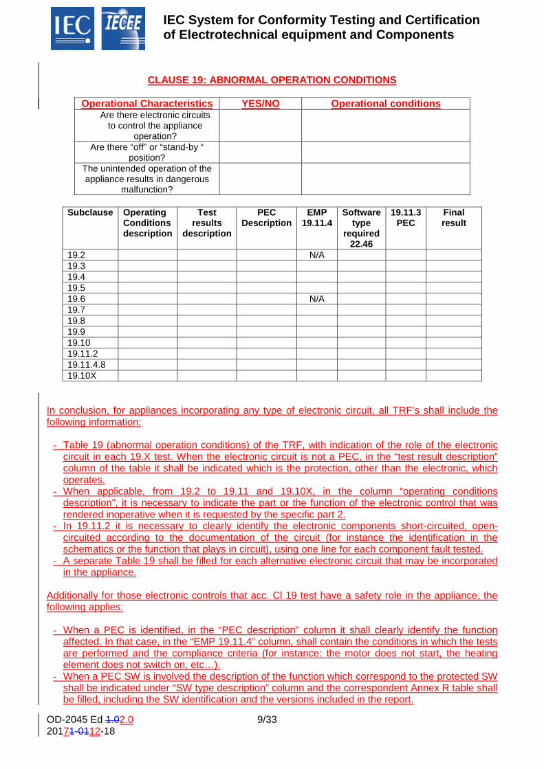
CLAUSE 19: ABNORMAL OPERATION CONDITIONS
Operational Characteristics YES/NO Operational conditions
Are there electronic circuits to control the appliance
operation?
Are there “off” or “stand-by “ position?
The unintended operation of the appliance results in dangerous
malfunction?
Subclause Operating
Conditions description
Test results
description
PEC Description
EMP 19.11.4
Software type
required 22.46
19.11.3 PEC
Final result
19.2 N/A 19.3 19.4 19.5 19.6 N/A 19.7 19.8 19.9 19.10 19.11.2 19.11.4.8 19.10X
In conclusion, for appliances incorporating any type of electronic circuit, all TRF’s shall include the following information:
- Table 19 (abnormal operation conditions) of the TRF, with indication of the role of the electronic
circuit in each 19.X test. When the electronic circuit is not a PEC, in the “test result description” column of the table it shall be indicated which is the protection, other than the electronic, which operates.
- When applicable, from 19.2 to 19.11 and 19.10X, in the column “operating conditions description”, it is necessary to indicate the part or the function of the electronic control that was rendered inoperative when it is requested by the specific part 2.
- In 19.11.2 it is necessary to clearly identify the electronic components short-circuited, open-circuited according to the documentation of the circuit (for instance the identification in the schematics or the function that plays in circuit), using one line for each component fault tested.
- A separate Table 19 shall be filled for each alternative electronic circuit that may be incorporated in the appliance.
Additionally for those electronic controls that acc. Cl 19 test have a safety role in the appliance, the following applies:
- When a PEC is identified, in the “PEC description” column it shall clearly identify the function
affected. In that case, in the “EMP 19.11.4” column, shall contain the conditions in which the tests are performed and the compliance criteria (for instance: the motor does not start, the heating element does not switch on, etc…).
- When a PEC SW is involved the description of the function which correspond to the protected SW shall be indicated under “SW type description” column and the correspondent Annex R table shall be filled, including the SW identification and the versions included in the report.
IEC System for Conformity Testing and Certification of Electrotechnical equipment and Components
OD-2045 Ed 1.02.0 10/33 20171-0112-18
- The identification of the documents used in the HW and SW analysis (Reference number of the document or reference of the schematics) and the date of issue or version of the documents shall be indicated in the correspondent Annex R item.
The EMP tests or the SW analysis that can be considered covered by another test reports issued from a valid (recognised) CBTL shall be reflected in the relevant Table 19 column (“EMP 19.11.4”) or in the relevant TRF Annex (Annex R1 or R2) with the correspondent Test Report Number. Note: an additional annex can be used to provide the above information.
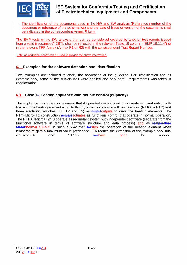
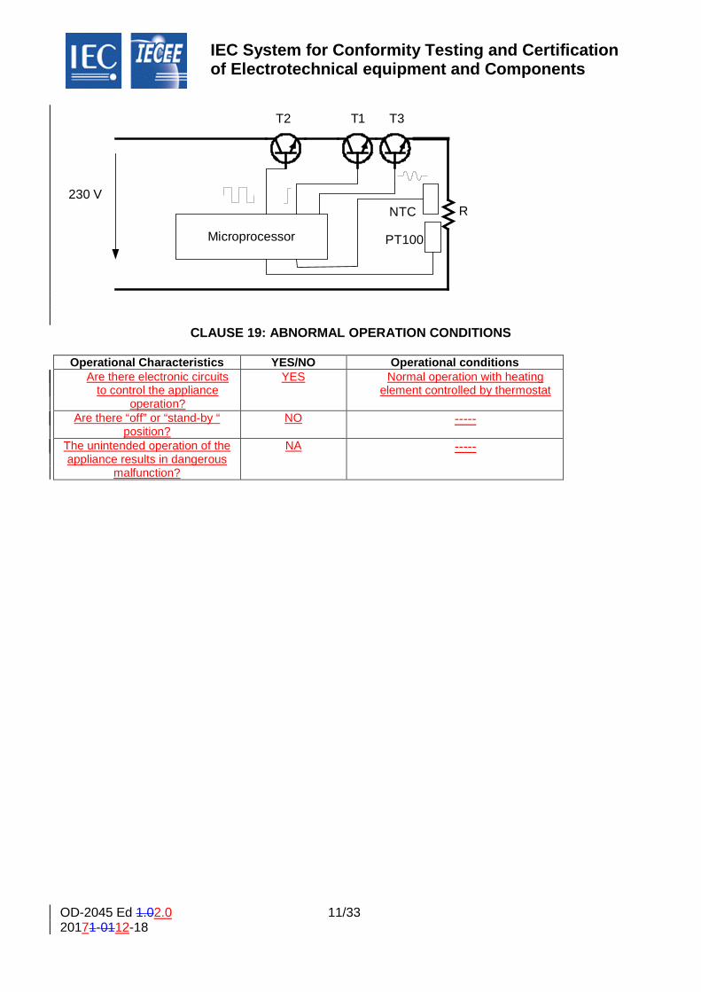
Examples for the software detection and identification 6. Two examples are included to clarify the application of the guideline. For simplification and as example only, some of the sub-clauses were applied and only part 1 requirements was taken in consideration 6.1 Case 1:. Heating appliance with double control (duplicity) The appliance has a heating element that if operated uncontrolled may create an overheating with fire risk. The heating element is controlled by a microprocessor with two sensors (PT100 y NTC) and three electronic switches (T1, T2 and T3) as outputoutputs to drive the heating elements. The NTC+Micro+T1 construction actuateactuates as functional control that operate in normal operation. The PT100+Micro+T2/T3 operate as redundant system with independent software (separate from the functional software in terms of software structure and data process) and as temperature limiterthermal cut-out, in such a way that cutstop the operation of the heating element when temperature gets a maximum value predefined. To reduce the extension of the example only sub-clauses19.4 and 19.11.2 willhave been be applied.
IEC System for Conformity Testing and Certification of Electrotechnical equipment and Components
OD-2045 Ed 1.02.0 11/33 20171-0112-18
CLAUSE 19: ABNORMAL OPERATION CONDITIONS
Operational Characteristics YES/NO Operational conditions Are there electronic circuits
to control the appliance operation?
YES Normal operation with heating element controlled by thermostat
Are there “off” or “stand-by “ position?
NO -----
The unintended operation of the appliance results in dangerous
malfunction?
NA -----
Microprocessor
NTC
PT100
230 VR
T1T2 T3
IEC System for Conformity Testing and Certification of Electrotechnical equipment and Components
OD-2045 Ed 1.02.0 12/33 © IEC – IECEE 20181 20171-0112-18
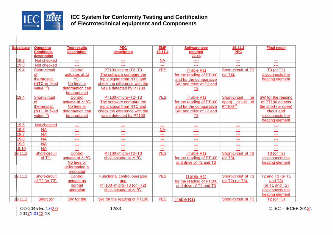
Subclause Operating Conditions description
Test results description
PEC description
EMP 19.11.4
Software type required
22.46
19.11.3 PEC
Final result
19.2 Not checked --- --- NA ---- --- --- 19.3 Not checked --- --- --- --- --- --- 19.4 Short-circuit
of thermostat. (NTC in fixed value (1))
Control actuates at ∆t
ºC. No fires or
deformation can be produced
PT100+micro+T2+T3 The software compare the input signal from NTC and
check the difference with the value detected by PT100
YES (Table R1) for the reading of PT100 and for the comparative SW and drive of T2 and
T3
Short-circuit of T2 (or T3).
T3 (or T2) disconnects the heating element
19.4 Short-circuit of thermostat. (NTC in fixed value (1))
Control actuate at ∆t ºC.
No fires or deformation can
be produced
PT100+micro+T2+T3 The software compare the input signal from NTC and
check the difference with the value detected by PT100
YES (Table R1) for the reading of PT100 and for the comparative SW and drive of T2 and
T3
Short-circuit (or open) circuit of PT100(2)
SW for the reading of PT100 detects
the short (or open) circuit and
disconnects the heating element
19.5 Not checked --- --- --- --- --- --- 19.6 NA --- --- NA ---- --- --- 19.7 NA --- --- --- --- --- --- 19.8 NA --- --- --- --- --- --- 19.9 NA --- --- --- --- --- --- 19.10 NA --- --- --- --- --- ---
19.11.2 Short-circuit of T1.
Control actuate at ∆t ºC.
No fires or deformation is
produced
PT100+micro+T2+T3 shall actuate at ∆t ºC.
YES (Table R1) for the reading of PT100 and drive of T2 and T3
Short-circuit of T2 (or T3).
T3 (or T2) disconnects the heating element
19.11.2 Short-circuit of T2 (or T3).
Control actuate as
normal operation
Functional control operates and
PT100+micro+T3 (or +T2) shall actuate at ∆t ºC.
YES (Table R1) for the reading of PT100 and drive of T2 and T3
Short-circuit of T1 (or T2) (or T3).
T2 and T3 (or T1 and T3)
(or T1 and T2) disconnects the heating element
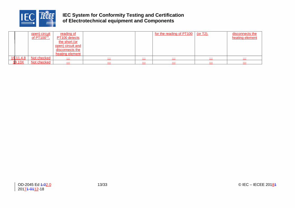
19.11.2 Short (or SW for the SW for the reading of PT100 YES (Table R1) Short-circuit of T3 T2 (or T3)
IEC System for Conformity Testing and Certification of Electrotechnical equipment and Components
OD-2045 Ed 1.02.0 13/33 © IEC – IECEE 20181 20171-0112-18
open) circuit of PT100(3).
reading of PT100 detects the short (or
open) circuit and disconnects the heating element
for the reading of PT100
(or T2).
disconnects the heating element
19.11.4.8 Not checked --- --- --- --- --- --- 19.10X Not checked --- --- --- --- --- ---
IEC System for Conformity Testing and Certification of Electrotechnical equipment and Components
OD-2045 Ed 1.02.0 14/33 20171-0112-18
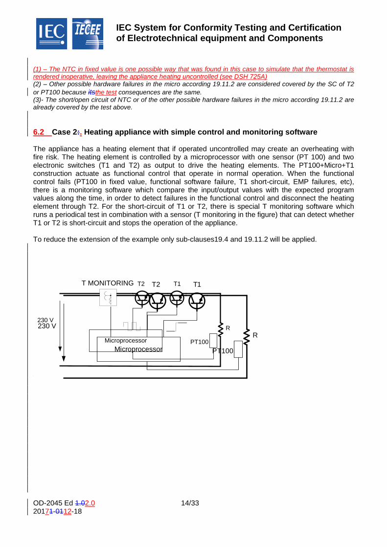
(1) – The NTC in fixed value is one possible way that was found in this case to simulate that the thermostat is rendered inoperative, leaving the appliance heating uncontrolled (see DSH 725A) (2) – Other possible hardware failures in the micro according 19.11.2 are considered covered by the SC of T2 or PT100 because itsthe test consequences are the same. (3)- The short/open circuit of NTC or of the other possible hardware failures in the micro according 19.11.2 are already covered by the test above. 6.2 Case 2:. Heating appliance with simple control and monitoring software The appliance has a heating element that if operated uncontrolled may create an overheating with fire risk. The heating element is controlled by a microprocessor with one sensor (PT 100) and two electronic switches (T1 and T2) as output to drive the heating elements. The PT100+Micro+T1 construction actuate as functional control that operate in normal operation. When the functional control fails (PT100 in fixed value, functional software failure, T1 short-circuit, EMP failures, etc), there is a monitoring software which compare the input/output values with the expected program values along the time, in order to detect failures in the functional control and disconnect the heating element through T2. For the short-circuit of T1 or T2, there is special T monitoring software which runs a periodical test in combination with a sensor (T monitoring in the figure) that can detect whether T1 or T2 is short-circuit and stops the operation of the appliance. To reduce the extension of the example only sub-clauses19.4 and 19.11.2 will be applied.
MicroprocessorMicroprocessor
PTPT
100100
230 230
VV R
R
T T1 1T T2 2T MONITORING

IEC System for Conformity Testing and Certification of Electrotechnical equipment and Components
OD-2045 Ed 1.02.0 15/33 20171-0112-18
CLAUSE 19: ABNORMAL OPERATION CONDITIONS
Operational Characteristics YES/NO Operational conditions Are there electronic circuits
to control the appliance operation?
YES
Normal operation with heating element controlled by
thermostat Are there “off” or “stand-by “
position? NO ----
The unintended operation of the appliance results in dangerous
malfunction?
N/A -----

IEC System for Conformity Testing and Certification of Electrotechnical equipment and Components
OD-2045 Ed 1.02.0 16/33 © IEC – IECEE 20181 20171-0112-18
Subclause Operating
Conditions description
Test results description
PEC Description
EMP 19.11.4
Software type required 22.46
19.11.3 PEC
Final result
19.2 Not checked --- --- NA ---- --- --- 19.3 Not checked --- --- --- --- --- --- 19.4 Short-circuit
of thermostat. (PT100 in fixed value (1))
Control detects an incorrect ∆t ºC/time. No fires or deformation is produced
The software compare the input/outputs signals and check the difference with the predefined ∆tºC/time values
YES (table R1) for the reading of PT100 and for the ∆tºC/time monitoring and drive of T1/T2
Short-circuit of T1 or T2 (2)
T monitoring system stops the operation of the appliance. No further Cl 19 test are possible after it
19.5 Not checked --- --- --- --- --- --- 19.6 NA --- --- NA ---- --- --- 19.7 NA --- --- --- --- --- --- 19.8 NA --- --- --- --- --- --- 19.9 NA --- --- --- --- --- --- 19.10 NA --- --- --- --- --- --- 19.11.2 Short-circuit
of T1 or T2.
T monitoring system Stops the operation of the appliance
T monitoring The software periodically open T1 and T2 and check if heating element is in operation (i.e current detection)
YES (table R1) for the reading of T monitoring and for the T1 and T2 checking and driving
Short-circuit of T2 or T1.
T monitoring system stops the operation of the appliance. No further Cl 19 test are possible after it
19.11.2 Short/open circuit of PT100(2).
SW for the reading of PT100 detects the short/open circuit and disconnects the heating element
SW for the reading of PT100
YES (table R1) for the reading of PT100 and drive of T1 and T2
Short-circuit of T1 or T2.
T monitoring system Stops the operation of the appliance. No further Cl 19 test are possible after it
19.11.4.8 Not checked --- --- --- --- --- --- 19.10X Not checked --- --- --- --- --- ---
1) – The NTC in fixed value is the better way that was found in this case to simulate that the thermostat is rendered inoperative, leaving the appliance heating uncontrolled (2) – Other possible hardware failures in the micro according 19.11.2 are considered covered by the SC of T2 because its consequences are the same
OD-2045 Ed 1.02.0 17/33 20171-0112-18
6. Process of Audit Trail, Items & Evaluation for Data Exchange Among NCB’s and 7.CBTL’s
The general processprocces shall include the following phases:
• Project definition: o Concept of operation o Requirements and architecturearquitecture o Detailed design
• Implementation • Project test and integration
o Integration test and verification o System verification and validation o Operation and maintenance
For each phase the following items could be documented and used to define the information that needs to be gathered by NCB A and conveyed to NCB B, with documentation references from the original certification that are traceable throughoutthroughtout the lifecycle and demonstrate the objective evidence gather during the audit of the manufacturer’smanufacturers software and processes.
7.1 Concept of Operation / Safety Requirements specifications: The specification of the software safety requirements shall include: (IEC 60335-1 ed5 R.3.2)
• a description of each safety related function to be implemented, including its response time(s)
• functions related to the application • including their related software faults required to be controlled; • functions related to the detection, • annunciation and management of software or hardware faults; • a description of interfaces between software and hardware; • a description of interfaces between any safety and non-safety related functions; • a description of any compiler used to generate the object code from the source code,
including details of any compiler switch settings used such as library function options, memory model, optimization, SRAM details, clock rate and chip details;
• a description of any linker used to link the object code to executable library routines.
Technique / Measure: • Semi-formal methods • Logical/functional block diagrams • Sequence diagrams • Finite state machines/state transition diagrams • Decision/truth tables

OD-2045 Ed 1.02.0 18/33 20171-0112-18
7.2 Hard- and Software architecture
• interactions between hardware and software • partitioning into modules and their allocation to the specified safety functions; • hierarchy and call structure of the modules (control flow); • interrupt handling; • data flow and restrictions on data access; • architecture and storage of data; • time-based dependencies of sequences and data.
Technique / Measure: • Data flow diagrams
7.3 Module design and coding Software module design and coding shall be implemented in a way that is traceable to the software architecture and requirements. The module design shall specify:
• function(s), • interfaces to other modules, • data.
Defensive programming (IEC 61508-7, Sub-clause Subclause C.2.5) is recommended (e.g. range checks, check for division by 0, plausibility checks).
Technique / Measure:
• Limited size of software modules IEC 61508-7, C.2.9 • Information hiding / encapsulation IEC 61508-7, C.2.8 • One entry / one exit point in subroutines and functions IEC 61508-7, C.2.9 • Fully defined interface IEC 61508-7, C.2.9
6.17.4 Software code shall be structured. • keep the number of possible paths through a software module small, and the relation between
the input and output parameters as simple as possible; • avoid complicated branching and, in particular, avoid unconditional jumps (GOTO) in higher level
languages; • where possible, relate loop constraints and branching to input parameters; • avoid using complex calculations as the basis of branching and loop decisions.
Technique / Measure: • Use of coding standard (see NOTE) IEC 61508-7, C.2.6.2 • No use of dynamic objects and variables (see NOTE) IEC 61508-7, C.2.6.3 • Limited use of interrupts IEC 61508-7, C.2.6.5 • Limited use of pointers IEC 61508-7, C.2.6.6 • Limited use of recursion IEC 61508-7, C.2.6.7 • No unconditional jumps in programs in higher level languages IEC 61508-7, C.2.6.2
Note: NOTE
OD-2045 Ed 1.02.0 19/33 20171-0112-18
Dynamic objects and/or variables are allowed if a compiler is used which ensures that sufficient memory for all dynamic objects and/or variables will be allocated before runtime, or which inserts runtime checks for the correct online allocation of memory. 6.27.5 Audit Trail and Evidence of Compliance for NCB Information Exchange In following the above requirements, an audit trail of both actual data and document references may be provided as the basis for exchange of information between the original certifier (NCB A) and the secondary certifier (NCB B) accepting data via the IECEE SBCB Scheme: 6.2.17.5.1 The following details should be captured in the original certification report (per
the above mentioned requirements of IEC 60335): • a description of each safety related function to be implemented, including its response
time(s) • functions related to the application including their related software faults required to be
controlled; • functions related to the detection, annunciation and management of software or
hardware faults; • a description of interfaces between software and hardware; • a description of interfaces between any safety and non-safety related functions;
6.2.27.5.2 7.5. The following items should be captured briefly (make, model, version) in
the report and details may be captured via manufacturer’s documentation reference(s): • a description of any compiler used to generate the object code from the source code,
including details of any compiler switch settings used such as library function options, memory model, optimization, SRAM details, clock rate and chip details;
• a description of any linker used to link the object code to executable library routines. 6.2.37.5.3 7.5. The following items should be captured in the original certification report
(per above requirements) supported by references to the manufacturer’s documentation for specific details: • Semi-formal methods • Logical/functional block diagrams • Sequence diagrams • Finite state machines/state transition diagrams • Decision/truth tables
7.5.4 7.5. The following should be documented in the report and the specific Technique /
Measure referenced in the report via reference to manufacturer’smanufacturer’s documentation of data flows: • interactions between hardware and software • partitioning into modules and their allocation to the specified safety functions; • hierarchy and call structure of the modules (control flow); • interrupt handling; • data flow and restrictions on data access; • architecture and storage of data; • time-based dependencies of sequences and data.
6.2.47.5.5 The following may be demonstrated by providing excerpts of safety related
code modules during the information exchange between NCB’s or via NCB B’s
OD-2045 Ed 1.02.0 20/33 20171-0112-18
contact with the manufacturer (comparable to the situation where NCB B requests a product sample from the manufacturer): • interactions between hardware and software • partitioning into modules and their allocation to the specified safety functions; • hierarchy and call structure of the modules (control flow); • interrupt handling; • data flow and restrictions on data access; • architecture and storage of data; • time-based dependencies of sequences and data.
6.2.57.5.6 7.5. The elements of item 1 (above) should be traceable to the test plan for the product / software in that specific test cases, expected results, and actual results of testing should be identified and reflected in the report (via manufacturer’s test report reference) establishing that all safety-related functions have been tested under normal and abnormal conditions for relevant failure mode and stress conditions (e.g. single bit faults, DC fault, etc…)
6.2.67.5.7 5.7 The items 1-6 above should establish a level of confidence from
documented audit trail evidence that all safety relevant portions of the code have been evaluated by NCB A for the following attributes: • keep the number of possible paths through a software module small, and the relation
between the input and output parameters as simple as possible; • avoid complicated branching and, in particular, avoid unconditional jumps (GOTO) in higher
level languages; • where possible, relate loop constraints and branching to input parameters; • avoid using complex calculations as the basis of branching and loop decisions.
Technique / Measure:
• Use of coding standard (see Note) NOTE) IEC 61508-7, C.2.6.2 • No use of dynamic objects and variables (see NoteNOTE) IEC 61508-7, C.2.6.3 • Limited use of interrupts IEC 61508-7, C.2.6.5 • Limited use of pointers IEC 61508-7, C.2.6.6 • Limited use of recursion IEC 61508-7, C.2.6.7 • No unconditional jumps in programs in higher level languages IEC 61508-7, C.2.6.2
Note:
NOTE: Dynamic objects and/or variables are allowed if a compiler is used which ensures that sufficient memory for all dynamic objects and/or variables will be allocated before runtime, or which inserts runtime checks for the correct online allocation of memory.
7. Process to identify the SW and the way to reflect it in the TRF 8. 8.1 Software designation Definitions for the purpose of this chapter of the guide: Software designation: Name given by the programmer to the software included in a programmable system which allows its traceability through the documentation required by the applicable standards. In order to obtain that traceability the Software designation shall have the following properties:
OD-2045 Ed 1.02.0 21/33 20171-0112-18
• The designation must be unique, in such a way that modifications of the software imply
modification of the designation. • In order to track software modifications, a document with a dated historic register (see notes
below) must be kept updated by the manufacturer.
OD-2045 Ed 1.02.0 22/33 20171-0112-18
Notes:
- A product may include several programmable systems which can include different software. Each shall have its own designation. For instance, an induction hob may have a user interface with a microcontroller and an electronic power control with another microcontroller. Each microcontroller shall have its own designation.
- A possible format of a dated historic register referred above may be a document including a table with a row for each modified version of the software. The table should include at least the essence of the following columns: “software designation”, “date of issue” and “summary of the changes from previous versions”.
- Different products of a family covered in a test report may include software with small functional differences. The uniqueness of the designation, imply that each variation must have a different designation. The designation system used by the manufacturer should cover the variations and the modifications in such a way that the evolution of the software may be tracked in the historic register
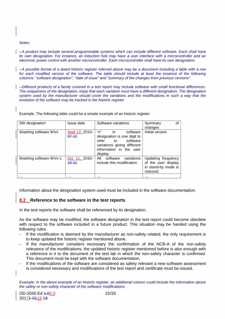
Example: The following table could be a simple example of an historic register
SW designation Issue date Software variations Summary of
changes Washing software WVx Sept 12, 2010-
07-12 “x” in software designation is one digit to refer to software variations giving different information in the user display.
Initial version
Washing software WVx-1 Oct 11, 2010-10-11
All software variations include this modification
Updating frequency of the user display in stand-by mode is reduced.
… … … …
Information about the designation system used must be included in the software documentation. 8.2 Reference to the software in the test reports In the test reports the software shall be referenced by its designation. As the software may be modified, the software designation in the test report could become obsolete with respect to the software included in a future product. This situation may be handed using the following rules: − If the modification is deemed by the manufacturer as non-safety related, the only requirement is
to keep updated the historic register mentioned above. − If the manufacturer considers necessary the confirmation of the NCB-A of the non-safety
relevance of the modifications, the updated historic register mentioned before is also enough with a reference in it to the document of the test lab in which the non-safety character is confirmed. This document must be kept with the software documentation.
− If the modifications of the software are considered as safety relevant a new software assessment is considered necessary and modifications of the test report and certificate must be issued.
Example: In the above example of an historic register, an additional column could include the information above the safety or non-safety character of the software modifications.
OD-2045 Ed 1.02.0 23/33 20171-0112-18
NCB-B can ask to the manufacturer for the historic register mentioned above to check that the product to be certified is covered by the software version initially certified, taking into account the rules above. 8.3 Evidence of identity of the software in a product In a product, the software cannot be identified in the same way that can be done with a physical component. To address this situation it is advisable ( to be changed for mandatory for certification?)after modification of the standard) that the product havehas provisions to give information about the software included in it. The information provided should allow tracking the software designation in its documentation and in the test report.
Examples: Products that have visual displays could show the software designation (or some associated code explained in the documentation) during some time after switch-on. In products which have also a user interface, this information can be showed after using a certain key combination or other operations. Physical labels in the hardware are also possible.
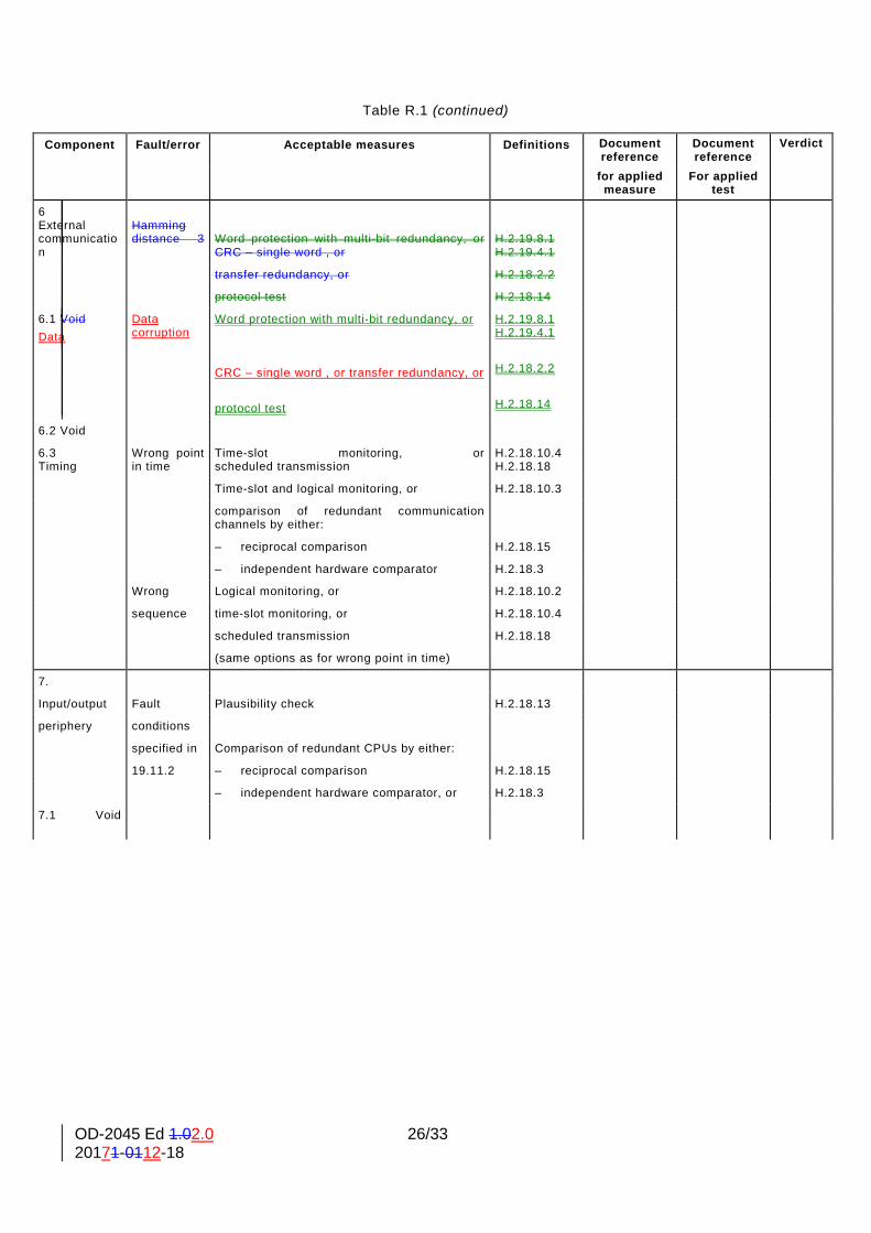
8. Process of audit and evaluation of the SW allows to fulfils the Table R1 or R2 9. According to requirements of sub-clausesubclause R.3.2.2.1 the architecture for techniques and measures to control fault/errors shall be specified by the manufacturer and checked by NCB A. Acceptable techniques for the specification are described in R.3.2.2.1. The requirements of R.2.2.5 and R.2.2.6 defines that the source code of the applied measures has to be inspected by the NCB A. We recommend that this will be carried out together with the software developer (software development team). In the test report shall be introduced the relevant document reference, in which the chosen measures are described. . In the column Verdict NCB A shall state which measures were applied. Furthermore the sub-clausesubclause R.2.2.5 requiresrequire the testing of the source code. To fulfil this requirement, the software tester (software test team) of the manufacturer shall define suitable test cases. The test cases have to be carried out and documented together with the test plan accordingly. A description of the test environment (Debugger, Emulator, Simulator, Test equipment) shall be included. Afterwards relevant tests shall be repeated together with NCB A by spot checks. In the column column “Document reference for applied tests” shall be introduced the document reference for the applied test cases, test data and test environment. For the more detailed description in the test report IEC60335_1m, the following tables shall be added. With a document reference a better confidence for NCB B can be provided. Details about the content of the documents shall not be requested by NCB B.
OD-2045 Ed 1.02.0 24/33 20171-0112-18
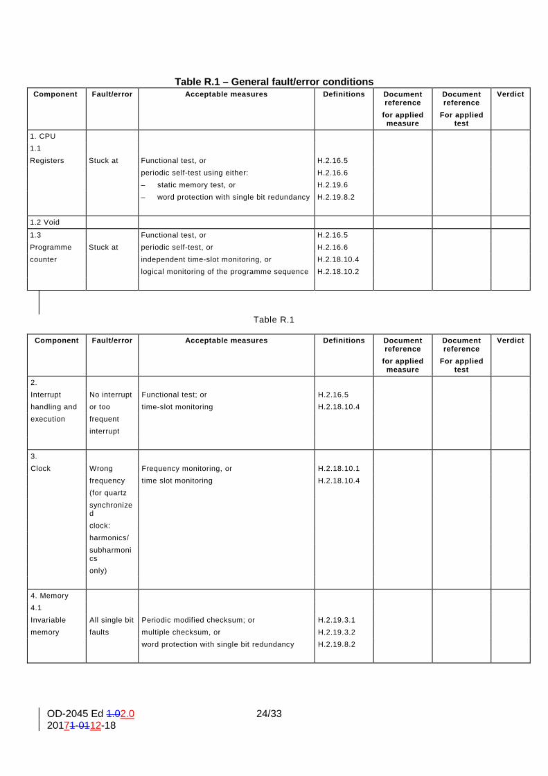
Table R.1 – General fault/error conditions
Component Fault/error Acceptable measures Definitions Document reference
Document reference
Verdict
for applied measure
For applied test
1. CPU 1.1 Registers Stuck at Functional test, or H.2.16.5 periodic self-test using either: H.2.16.6 – static memory test, or H.2.19.6 – word protection with single bit redundancy H.2.19.8.2
1.2 Void
1.3 Functional test, or H.2.16.5 Programme Stuck at periodic self-test, or H.2.16.6 counter independent time-slot monitoring, or H.2.18.10.4 logical monitoring of the programme sequence H.2.18.10.2
Table R.1
Component Fault/error Acceptable measures Definitions Document reference
Document reference
Verdict
for applied measure
For applied test
2. Interrupt No interrupt Functional test; or H.2.16.5 handling and or too time-slot monitoring H.2.18.10.4 execution frequent interrupt
3. Clock Wrong Frequency monitoring, or H.2.18.10.1 frequency time slot monitoring H.2.18.10.4 (for quartz synchronize
d
clock: harmonics/ subharmoni
cs
only)
4. Memory 4.1 Invariable All single bit Periodic modified checksum; or H.2.19.3.1 memory faults multiple checksum, or H.2.19.3.2 word protection with single bit redundancy H.2.19.8.2
OD-2045 Ed 1.02.0 25/33 20171-0112-18
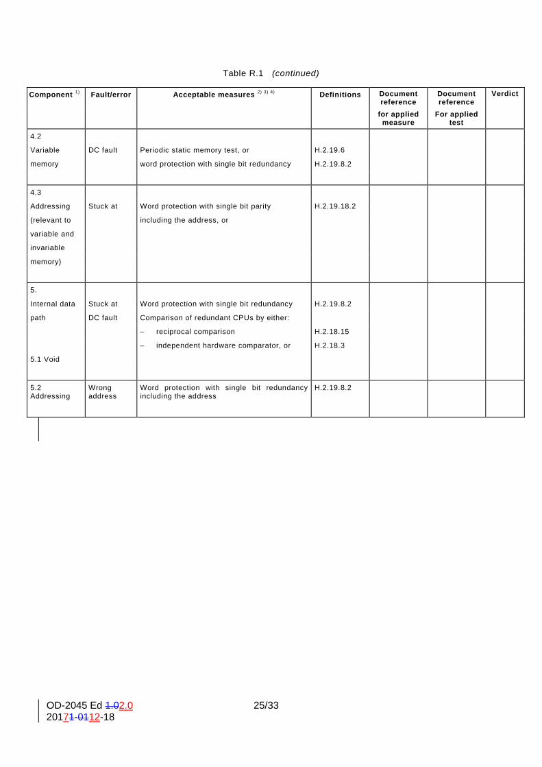
Table R.1 (continued)
Component 1) Fault/error Acceptable measures 2) 3) 4) Definitions Document reference
Document reference
Verdict
for applied measure
For applied test
4.2
Variable DC fault Periodic static memory test, or H.2.19.6
memory word protection with single bit redundancy H.2.19.8.2
4.3
Addressing Stuck at Word protection with single bit parity H.2.19.18.2
(relevant to including the address, or
variable and
invariable
memory)
5.
Internal data Stuck at Word protection with single bit redundancy H.2.19.8.2
path DC fault Comparison of redundant CPUs by either:
– reciprocal comparison H.2.18.15
– independent hardware comparator, or H.2.18.3
5.1 Void
5.2 Addressing
Wrong address
Word protection with single bit redundancy including the address
H.2.19.8.2
OD-2045 Ed 1.02.0 26/33 20171-0112-18
Table R.1 (continued)
Component Fault/error Acceptable measures Definitions Document reference
Document reference
Verdict
for applied measure
For applied test
6 External communication
Hamming distance 3
Word protection with multi-bit redundancy, or CRC – single word , or
H.2.19.8.1 H.2.19.4.1
transfer redundancy, or H.2.18.2.2
protocol test H.2.18.14
6.1 Void Data
Data corruption
Word protection with multi-bit redundancy, or CRC – single word , or transfer redundancy, or protocol test
H.2.19.8.1 H.2.19.4.1 H.2.18.2.2 H.2.18.14
6.2 Void
6.3 Timing
Wrong point in time
Time-slot monitoring, or scheduled transmission
H.2.18.10.4 H.2.18.18
Time-slot and logical monitoring, or H.2.18.10.3
comparison of redundant communication channels by either:
– reciprocal comparison H.2.18.15
– independent hardware comparator H.2.18.3
Wrong Logical monitoring, or H.2.18.10.2
sequence time-slot monitoring, or H.2.18.10.4
scheduled transmission H.2.18.18
(same options as for wrong point in time)
7.
Input/output Fault Plausibility check H.2.18.13
periphery conditions
specified in Comparison of redundant CPUs by either:
19.11.2 – reciprocal comparison H.2.18.15
– independent hardware comparator, or H.2.18.3
7.1 Void
OD-2045 Ed 1.02.0 27/33 20171-0112-18
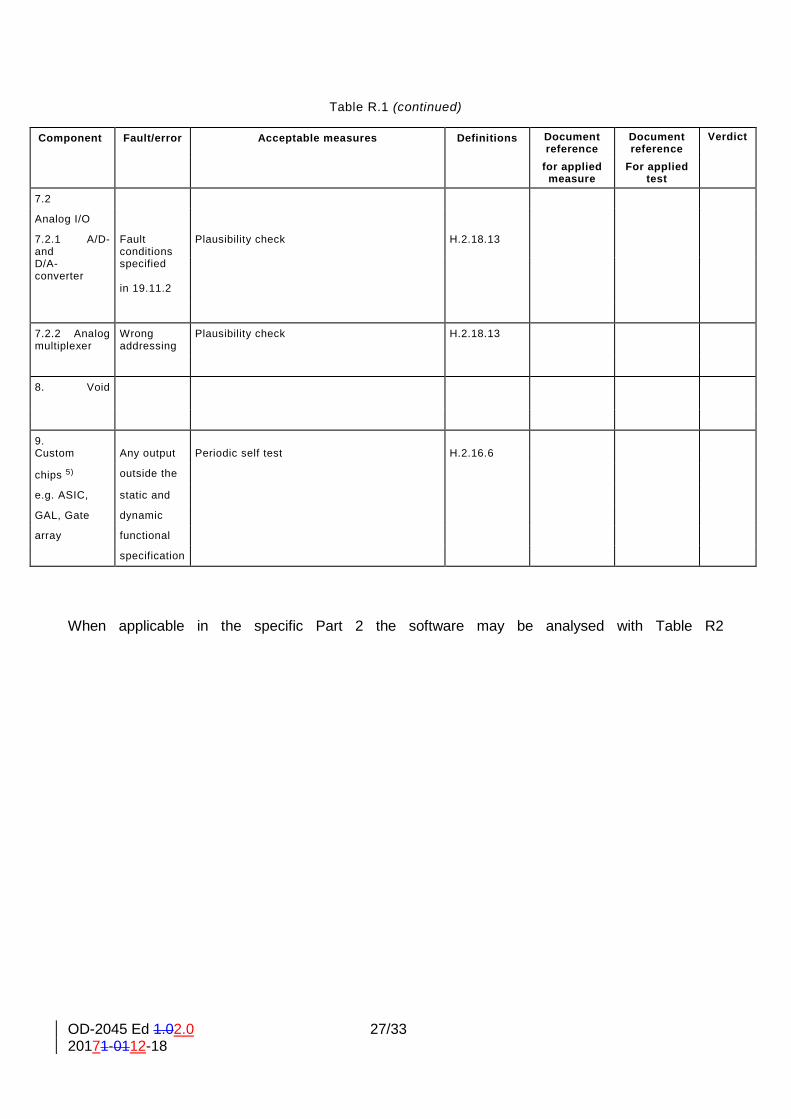
Table R.1 (continued)
Component Fault/error Acceptable measures Definitions Document reference
Document reference
Verdict
for applied measure
For applied test
7.2
Analog I/O
7.2.1 A/D- and
Fault conditions
Plausibility check H.2.18.13
D/A- converter
specified
in 19.11.2
7.2.2 Analog multiplexer
Wrong addressing
Plausibility check H.2.18.13
8. Void
9. Custom
Any output
Periodic self test
H.2.16.6
chips 5) outside the
e.g. ASIC, static and
GAL, Gate dynamic
array functional
specification
When applicable in the specific Part 2 the software may be analysed with Table R2
OD-2045 Ed 1.02.0 28/33 20171-0112-18
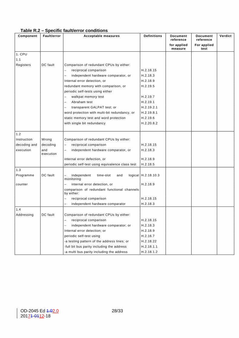
Table R.2 – Specific fault/error conditions Component Fault/error Acceptable measures Definitions Document
reference Document reference
Verdict
for applied measure
For applied test
1. CPU 1.1 Registers DC fault Comparison of redundant CPUs by either: – reciprocal comparison H.2.18.15 – independent hardware comparator, or H.2.18.3 Internal error detection, or H.2.18.9 redundant memory with comparison, or H.2.19.5 periodic self-tests using either – walkpat memory test H.2.19.7 – Abraham test H.2.19.1 – transparent GALPAT test; or H.2.19.2.1 word protection with multi-bit redundancy, or H.2.19.8.1 static memory test and word protection H.2.19.6 with single bit redundancy H.2.20.8.2
1.2 Instruction Wrong Comparison of redundant CPUs by either: decoding and decoding – reciprocal comparison H.2.18.15 execution and
execution – independent hardware comparator, or H.2.18.3
internal error defection, or H.2.18.9 periodic self-test using equivalence class test H.2.18.5
1.3 Programme DC fault – independent time-slot and logical
monitoring H.2.18.10.3
counter – internal error detection, or H.2.18.9 comparison of redundant functional channels
by either:
– reciprocal comparison H.2.18.15 – independent hardware comparator H.2.18.3
1.4 Addressing DC fault Comparison of redundant CPUs by either: – reciprocal comparison H.2.18.15 – independent hardware comparator; or H.2.18.3 Internal error detection; or H.2.18.9 periodic self-test using H.2.16.7 -a testing pattern of the address lines; or H.2.18.22 -full bit bus parity including the address H.2.18.1.1 -a multi bus parity including the address H.2.18.1.2
OD-2045 Ed 1.02.0 29/33 20171-0112-18
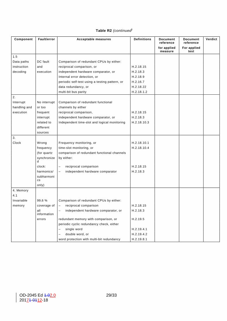
Table R2 (continued)
Component Fault/error Acceptable measures Definitions Document reference
Document reference
Verdict
for applied measure
For applied test
1.5 Data paths DC fault Comparison of redundant CPUs by either: instruction and reciprocal comparison, or H.2.18.15 decoding execution independent hardware comparator, or H.2.18.3 Internal error detection, or H.2.18.9 periodic self-test using a testing pattern, or H.2.16.7 data redundancy, or H.2.18.22 multi-bit bus parity H.2.18.1.2
2. Interrupt No interrupt Comparison of redundant functional handling and or too channels by either execution frequent reciprocal comparison, H.2.18.15 interrupt independent hardware comparator, or H.2.18.3 related to Independent time-slot and logical monitoring H.2.18.10.3 different sources
3. Clock Wrong Frequency monitoring, or H.2.18.10.1 frequency time-slot monitoring, or H.2.18.10.4 (for quartz comparison of redundant functional channels synchronize
d by either:
clock: – reciprocal comparison H.2.18.15 harmonics/ – independent hardware comparator H.2.18.3 subharmoni
cs
only)
4. Memory 4.1 Invariable 99,6 % Comparison of redundant CPUs by either: memory coverage of – reciprocal comparison H.2.18.15 all
information – independent hardware comparator, or H.2.18.3
errors redundant memory with comparison, or H.2.19.5 periodic cyclic redundancy check, either – single word H.2.19.4.1 – double word, or H.2.19.4.2 word protection with multi-bit redundancy H.2.19.8.1
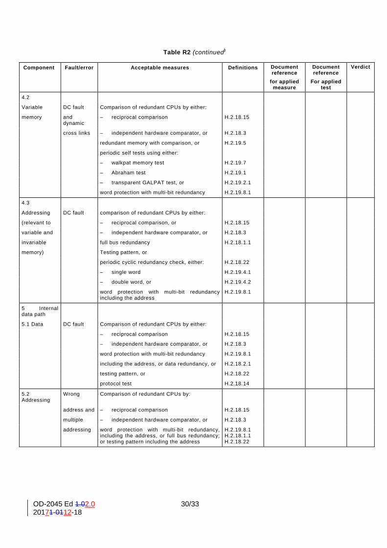
OD-2045 Ed 1.02.0 30/33 20171-0112-18
Table R2 (continued)
Component Fault/error Acceptable measures Definitions Document reference
Document reference
Verdict
for applied measure
For applied test
4.2
Variable DC fault Comparison of redundant CPUs by either:
memory and dynamic
– reciprocal comparison H.2.18.15
cross links – independent hardware comparator, or H.2.18.3
redundant memory with comparison, or H.2.19.5
periodic self tests using either:
– walkpat memory test H.2.19.7
– Abraham test H.2.19.1
– transparent GALPAT test, or H.2.19.2.1
word protection with multi-bit redundancy H.2.19.8.1
4.3
Addressing DC fault comparison of redundant CPUs by either:
(relevant to – reciprocal comparison, or H.2.18.15
variable and – independent hardware comparator, or H.2.18.3
invariable full bus redundancy H.2.18.1.1
memory) Testing pattern, or
periodic cyclic redundancy check, either: H.2.18.22
– single word H.2.19.4.1
– double word, or H.2.19.4.2
word protection with multi-bit redundancy including the address
H.2.19.8.1
5 Internal data path
5.1 Data DC fault Comparison of redundant CPUs by either:
– reciprocal comparison H.2.18.15
– independent hardware comparator, or H.2.18.3
word protection with multi-bit redundancy H.2.19.8.1
including the address, or data redundancy, or H.2.18.2.1
testing pattern, or H.2.18.22
protocol test H.2.18.14
5.2 Addressing
Wrong Comparison of redundant CPUs by:
address and – reciprocal comparison H.2.18.15
multiple – independent hardware comparator, or H.2.18.3
addressing word protection with multi-bit redundancy, including the address, or full bus redundancy; or testing pattern including the address
H.2.19.8.1 H.2.18.1.1 H.2.18.22
OD-2045 Ed 1.02.0 31/33 20171-0112-18
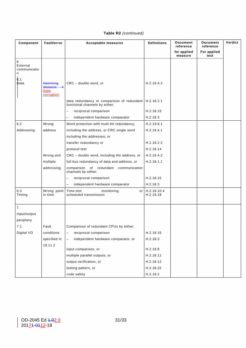
Table R2 (continued)
Component Fault/error Acceptable measures Definitions Document reference
Document reference
Verdict
for applied measure
For applied test
6 External communication
6.1 Data
Hamming distance 4 Data corruption
CRC – double word, or
H.2.19.4.2
data redundancy or comparison of redundant functional channels by either:
H.2.18.2.1
– reciprocal comparison H.2.18.15
– independent hardware comparator H.2.18.3
6.2 Wrong Word protection with multi-bit redundancy, H.2.19.8.1
Addressing address including the address, or CRC single word H.2.19.4.1
including the addresses, or
transfer redundancy or H.2.18.2.2
protocol test H.2.18.14
Wrong and CRC – double word, including the address, or H.2.19.4.2
multiple full bus redundancy of data and address, or H.2.18.1.1
addressing comparison of redundant communication channels by either:
– reciprocal comparison H.2.18.15
– independent hardware comparator H.2.18.3
6.3 Timing
Wrong point in time
Time-slot monitoring, or scheduled transmission
H.2.18.10.4 H.2.18.18
7.
Input/output
periphery
7.1 Fault Comparison of redundant CPUs by either:
Digital I/O conditions – reciprocal comparison H.2.18.15
specified in – independent hardware comparator, or H.2.18.3
19.11.2 input comparison, or
H.2.18.8
multiple parallel outputs; or H.2.18.11
output verification, or H.2.18.12
testing pattern, or H.2.18.22
code safety H.2.18.2

OD-2045 Ed 1.02.0 32/33 20171-0112-18
Table R2 (concluded)
Component Fault/error Acceptable measures Definitions Document reference
Document reference
Verdict
for applied measure
For applied test
7.2
Analog I/O
7.2.1 A/D- and
Fault conditions
D/A- convertor
specified Comparison of redundant CPUs by either:
In 19.11.2 – reciprocal comparison H.2.18.15
– independent hardware comparator, or H.2.18.3
input comparison, or H.2.18.8
multiple parallel outputs, or H.2.18.11
output verification, or H.2.18.12
testing pattern H.2.18.22
7.2.2 Analog multiplexer
Wrong addressing
Comparison of redundant CPUs by either:
– reciprocal comparison H.2.18.15
– independent hardware comparator, or H.2.18.3
input comparison or H.2.18.8
testing pattern H.2.18.22
8. Monitoring
Any output
Tested monitoring, or
H.2.18.21
devices and outside the redundant monitoring and comparison, or H.2.18.17
comparators static and error recognizing means H.2.18.6
dynamic
functional
specification
9. Custom
Any output
Periodic self-test and monitoring, or H.2.16.7
chips 5) outside the dual channel (diverse) with comparison, or H.2.16.2
e.g. ASIC, static and error recognizing means H.2.18.6
GAL, Gate dynamic
array functional
specification
9. Process to evaluate the software related safety independently of functional 10.
software and the way to proceed when changes are done on it. The software safety related and functional software shall be separated to avoid that functional part causes malfunction to safety related segments. With modular approach is easy to divide safety from functional code avoiding to insert safety and functional part of the software in the same module. Modular approach rule for the design and coding software requests that a software module should have a single well-defined task or function to fulfil (not all software design follow this rule).
OD-2045 Ed 1.02.0 33/33 20171-0112-18
Separation of safety and functional modules shall be implemented at data exchange, also. Functional and safety part of the software can exchange data each other but all safety related data must be managed directly from safety code which make available the information required to functional part and not the opposite. When is necessary to operate changes to safety software is very important that concepts explainexplained before are respected. In this way software changes can be managed by manufacturer and validate more easily. When manufacturer decide to make changes, at the beginning, shall provide documentation to describe modification. Information required should be:
• Detailed description of the modification • Impact of the modification related to the entire safety software with modified modules list with
new module versions • Source code comparison before/after modification • New software version, date of release and sign (checksum, CRC)
About source code comparison is possible to use software tools that make the comparison faster (text comparison). From this tools are possible to check source code changing and comments inside line, also. From documentation analysis can result:
• modifications are related to a specifically module or part of the program • modifications are related to several modules or parts of the program
If modifications are related to case 1 only affected module or part of the program have to be revalidated and the related function must be tested. If modifications are related to case 2 every affected module, or parts of the program have to be revalidated and related functions shall be tested. In case modified modules (or parts of the program) have more than one function, the impact of the modification shall indicate if functionsfunction inside the module are linked than all functions must be tested.