Embed Size (px)
Citation preview
I N D U C T O R S
VLF252010MT
VLF252012MT
VLF252015MT
VLF302510MT
VLF302512MT
VLF302515MT
VLF403210MT
VLF403212MT
VLF403215MT
VLF504010MT
VLF504012MT
VLF504015MT
May 2013
Inductors for Power Circuits Wound Ferrite
VLF-Mseries
(1/52)
I N D U C T O R S
001-01 / 20130516 / e531_vlf.fm
REMINDERS FOR USING THESE PRODUCTSBefore using these products, be sure to request the delivery specifications.
SAFETY REMINDERSPlease pay sufficient attention to the warnings for safe designing when using these products.
The storage period is less than 12 months. Be sure to follow the storage conditions (Temperature: 5 to 40°C, Humidity: 10 to 75% RH
or less).
If the storage period elapses, the soldering of the terminal electrodes may deteriorate.
Do not use or store in locations where there are conditions such as gas corrosion (salt, acid, alkali, etc.).
Before soldering, be sure to preheat components.
The preheating temperature should be set so that the temperature difference between the solder temperature and chip temperature
does not exceed 150°C.
Soldering corrections after mounting should be within the range of the conditions determined in the specifications.
If overheated, a short circuit, performance deterioration, or lifespan shortening may occur.
When embedding a printed circuit board where a chip is mounted to a set, be sure that residual stress is not given to the chip due to
the overall distortion of the printed circuit board and partial distortion such as at screw tightening portions.
Self heating (temperature increase) occurs when the power is turned ON, so the tolerance should be sufficient for the set thermal
design.
Carefully lay out the coil for the circuit board design of the non-magnetic shield type.
A malfunction may occur due to magnetic interference.
Use a wrist band to discharge static electricity in your body through the grounding wire.
Do not expose the products to magnets or magnetic fields.
Do not use for a purpose outside of the contents regulated in the delivery specifications.
The products listed on this catalog are intended for use in general electronic equipment (AV equipment, telecommunications
equipment, home appliances, amusement equipment, computer equipment, personal equipment, office equipment, measurement
equipment, industrial robots) under a normal operation and use condition.
The products are not designed or warranted to meet the requirements of the applications listed below, whose performance and/or
quality require a more stringent level of safety or reliability, or whose failure, malfunction or trouble could cause serious damage to
society, person or property.
If you intend to use the products in the applications listed below or if you have special requirements exceeding the range or conditions
set forth in the each catalog, please contact us.
(1) Aerospace/Aviation equipment
(2) Transportation equipment (cars, electric trains, ships, etc.)
(3) Medical equipment
(4) Power-generation control equipment
(5) Atomic energy-related equipment
(6) Seabed equipment
(7) Transportation control equipment
(8) Public information-processing equipment
(9) Military equipment
(10) Electric heating apparatus, burning equipment
(11) Disaster prevention/crime prevention equipment
(12) Safety equipment
(13) Other applications that are not considered general-purpose
applications
When designing your equipment even for general-purpose applications, you are kindly requested to take into consideration securing
protection circuit/device or providing backup circuits in your equipment.
REMINDERS
(2/52)
I N D U C T O R S
001-01 / 20130516 / e531_vlf.fm
• All specifications are subject to change without notice.
Inductors for Power CircuitsWound Ferrite
FEATURES
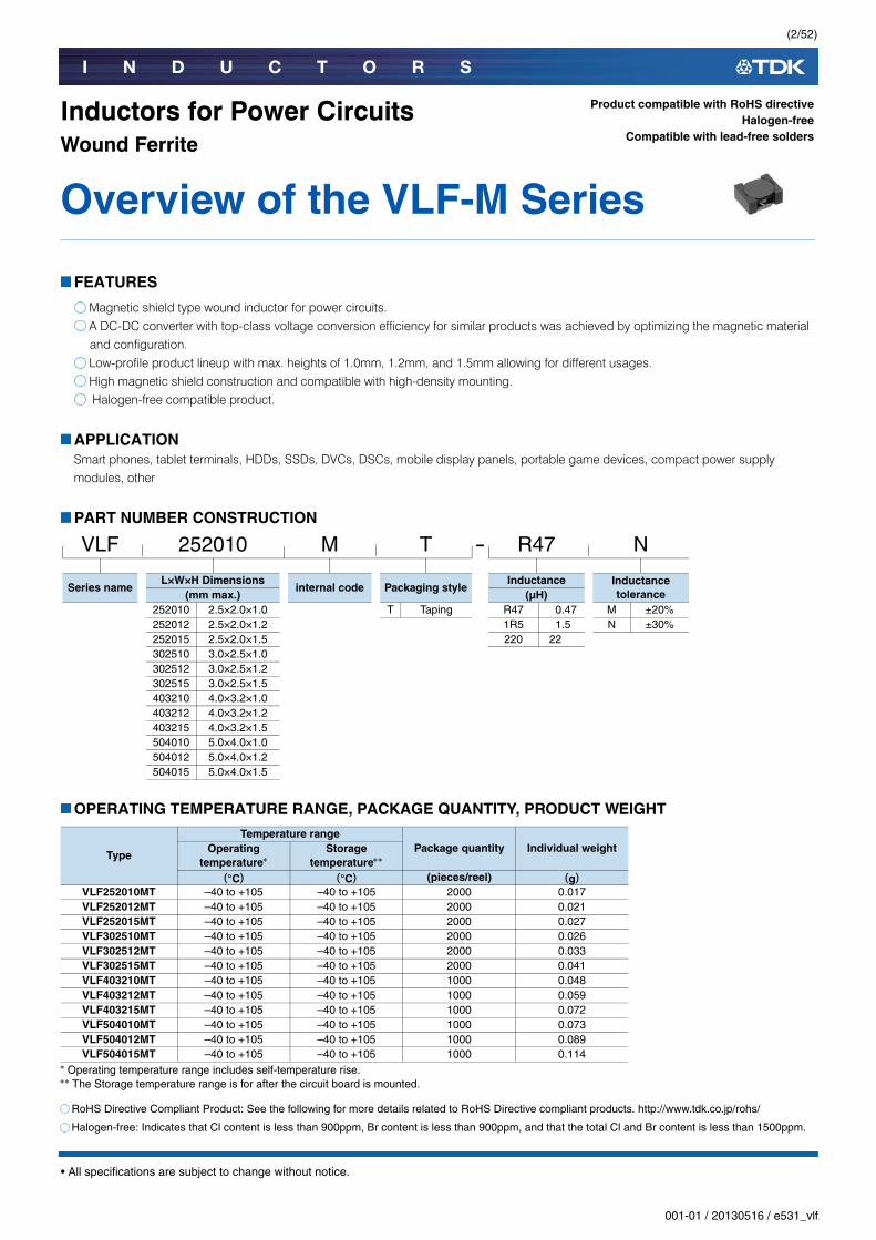
Magnetic shield type wound inductor for power circuits.A DC-DC converter with top-class voltage conversion efficiency for similar products was achieved by optimizing the magnetic material and configuration.Low-profile product lineup with max. heights of 1.0mm, 1.2mm, and 1.5mm allowing for different usages.High magnetic shield construction and compatible with high-density mounting. Halogen-free compatible product.
APPLICATIONSmart phones, tablet terminals, HDDs, SSDs, DVCs, DSCs, mobile display panels, portable game devices, compact power supply modules, other
PART NUMBER CONSTRUCTION
OPERATING TEMPERATURE RANGE, PACKAGE QUANTITY, PRODUCT WEIGHT
Operating temperature range includes self-temperature rise.The Storage temperature range is for after the circuit board is mounted.
Overview of the VLF-M Series
VLF 252010 M T - R47 N
Series nameL×W×H Dimensions
internal code Packaging styleInductance Inductance
tolerance(mm max.) (µH)252010 2.5×2.0×1.0 T Taping R47 0.47 M ±20%252012 2.5×2.0×1.2 1R5 1.5 N ±30%252015 2.5×2.0×1.5 220 22302510 3.0×2.5×1.0302512 3.0×2.5×1.2302515 3.0×2.5×1.5403210 4.0×3.2×1.0403212 4.0×3.2×1.2403215 4.0×3.2×1.5504010 5.0×4.0×1.0504012 5.0×4.0×1.2504015 5.0×4.0×1.5
Type
Temperature rangePackage quantity Individual weightOperating
temperatureStorage
temperature
(°C) (°C) (pieces/reel) (g)VLF252010MT –40 to +105 –40 to +105 2000 0.017VLF252012MT –40 to +105 –40 to +105 2000 0.021VLF252015MT –40 to +105 –40 to +105 2000 0.027VLF302510MT –40 to +105 –40 to +105 2000 0.026VLF302512MT –40 to +105 –40 to +105 2000 0.033VLF302515MT –40 to +105 –40 to +105 2000 0.041VLF403210MT –40 to +105 –40 to +105 1000 0.048VLF403212MT –40 to +105 –40 to +105 1000 0.059VLF403215MT –40 to +105 –40 to +105 1000 0.072VLF504010MT –40 to +105 –40 to +105 1000 0.073VLF504012MT –40 to +105 –40 to +105 1000 0.089VLF504015MT –40 to +105 –40 to +105 1000 0.114
Product compatible with RoHS directiveHalogen-free
Compatible with lead-free solders
RoHS Directive Compliant Product: See the following for more details related to RoHS Directive compliant products. http://www.tdk.co.jp/rohs/
Halogen-free: Indicates that Cl content is less than 900ppm, Br content is less than 900ppm, and that the total Cl and Br content is less than 1500ppm.
(3/52)
I N D U C T O R S
001-01 / 20130516 / e531_vlf.fm
• All specifications are subject to change without notice.
Overview of the VLF-M Series
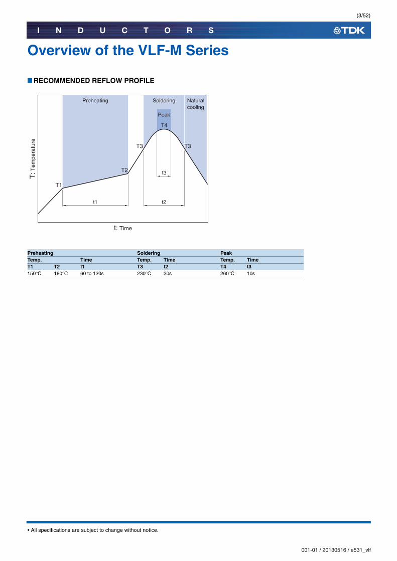
RECOMMENDED REFLOW PROFILE
Preheating Soldering PeakTemp. Time Temp. Time Temp. TimeT1 T2 t1 T3 t2 T4 t3150°C 180°C 60 to 120s 230°C 30s 260°C 10s
Naturalcooling
t3
t1
Preheating
t2
Soldering
T3 T3
T4
T2
T1
t: Time
Peak
T: T
empe
ratu
re

(4/52)
I N D U C T O R S
001-01 / 20130516 / e531_vlf.fm
• All specifications are subject to change without notice.
VLF-M series
VLF252010MT TypeSHAPE & DIMENSIONS
RECOMMENDED LAND PATTERN
2.5±
0.2
1.0m
ax.
2.0±0.2
(0.55)
( 0.8
5)
(0.55)(0.6)
Dimensions in mm
Dimensions in mm0.75 0.75
1.3
0.6
(5/52)
I N D U C T O R S
001-01 / 20130516 / e531_vlf.fm
• All specifications are subject to change without notice.
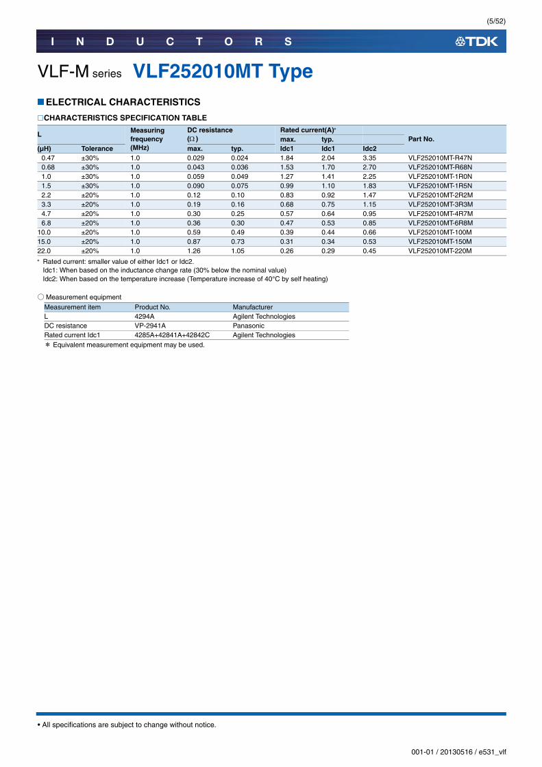
VLF-M series VLF252010MT TypeELECTRICAL CHARACTERISTICS
CHARACTERISTICS SPECIFICATION TABLE
Rated current: smaller value of either Idc1 or Idc2.Idc1: When based on the inductance change rate (30% below the nominal value)Idc2: When based on the temperature increase (Temperature increase of 40°C by self heating)
○Measurement equipment
* Equivalent measurement equipment may be used.
L Measuring frequency(MHz)
DC resistance ( )
Rated current(A)
Part No.max. typ.(µH) Tolerance max. typ. Idc1 Idc1 Idc2
0.47 ±30% 1.0 0.029 0.024 1.84 2.04 3.35 VLF252010MT-R47N0.68 ±30% 1.0 0.043 0.036 1.53 1.70 2.70 VLF252010MT-R68N1.0 ±30% 1.0 0.059 0.049 1.27 1.41 2.25 VLF252010MT-1R0N1.5 ±30% 1.0 0.090 0.075 0.99 1.10 1.83 VLF252010MT-1R5N2.2 ±20% 1.0 0.12 0.10 0.83 0.92 1.47 VLF252010MT-2R2M3.3 ±20% 1.0 0.19 0.16 0.68 0.75 1.15 VLF252010MT-3R3M4.7 ±20% 1.0 0.30 0.25 0.57 0.64 0.95 VLF252010MT-4R7M6.8 ±20% 1.0 0.36 0.30 0.47 0.53 0.85 VLF252010MT-6R8M
10.0 ±20% 1.0 0.59 0.49 0.39 0.44 0.66 VLF252010MT-100M15.0 ±20% 1.0 0.87 0.73 0.31 0.34 0.53 VLF252010MT-150M22.0 ±20% 1.0 1.26 1.05 0.26 0.29 0.45 VLF252010MT-220M
Measurement item Product No. ManufacturerL 4294A Agilent TechnologiesDC resistance VP-2941A PanasonicRated current Idc1 4285A+42841A+42842C Agilent Technologies
(6/52)
I N D U C T O R S
001-01 / 20130516 / e531_vlf.fm
• All specifications are subject to change without notice.
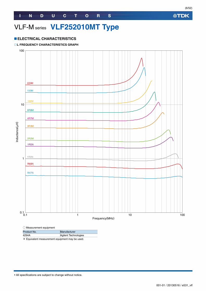
VLF-M series VLF252010MT TypeELECTRICAL CHARACTERISTICS
L FREQUENCY CHARACTERISTICS GRAPH
○Measurement equipment
* Equivalent measurement equipment may be used.
0.1
1
10
100
0.1 1 10 100
Indu
ctan
ce( µ
H)
Frequency(MHz)
3R3M
2R2M
1R5N
1R0N
R68N
R47N
100M
6R8M
4R7M
220M
150M
Product No. Manufacturer4294A Agilent Technologies

(7/52)
I N D U C T O R S
001-01 / 20130516 / e531_vlf.fm
• All specifications are subject to change without notice.
VLF-M series VLF252010MT TypeELECTRICAL CHARACTERISTICS
INDUCTANCE VS. DC BIAS CHARACTERISTICS GRAPH
○Measurement equipment
* Equivalent measurement equipment may be used.
DC current(A)
0.00 0.5 1 1.5 2 2.5
25
20
15
10
5
Indu
ctan
ce( μ
H)
3R3M
2R2M
1R5N1R0N
R68NR47N
100M
6R8M
4R7M
220M
150M
Product No. Manufacturer4285A+42841A+42842C Agilent Technologies

(8/52)
I N D U C T O R S
001-01 / 20130516 / e531_vlf.fm
• All specifications are subject to change without notice.
VLF-M series
VLF252012MT TypeSHAPE & DIMENSIONS
RECOMMENDED LAND PATTERN
2.5±
0.2
1.2m
ax.
2.0±0.2
(0.55)
( 0.8
5)
(0.55)(0.6)
Dimensions in mm
Dimensions in mm0.75 0.75
1.3
0.6
(9/52)
I N D U C T O R S
001-01 / 20130516 / e531_vlf.fm
• All specifications are subject to change without notice.
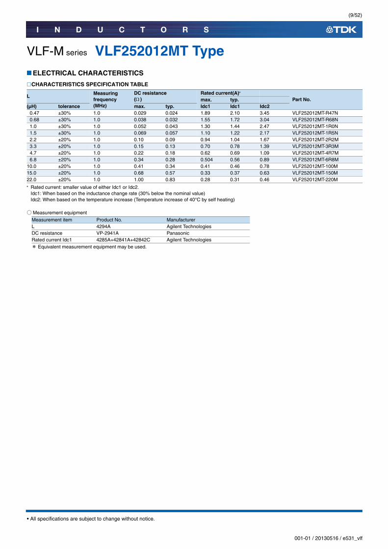
VLF-M series VLF252012MT TypeELECTRICAL CHARACTERISTICS
CHARACTERISTICS SPECIFICATION TABLE
Rated current: smaller value of either Idc1 or Idc2.Idc1: When based on the inductance change rate (30% below the nominal value)Idc2: When based on the temperature increase (Temperature increase of 40°C by self heating)
○Measurement equipment
* Equivalent measurement equipment may be used.
L Measuring frequency(MHz)
DC resistance ( )
Rated current(A)
Part No.max. typ.(µH) tolerance max. typ. Idc1 Idc1 Idc2
0.47 ±30% 1.0 0.029 0.024 1.89 2.10 3.45 VLF252012MT-R47N0.68 ±30% 1.0 0.038 0.032 1.55 1.72 3.04 VLF252012MT-R68N1.0 ±30% 1.0 0.052 0.043 1.30 1.44 2.47 VLF252012MT-1R0N1.5 ±30% 1.0 0.069 0.057 1.10 1.22 2.17 VLF252012MT-1R5N2.2 ±20% 1.0 0.10 0.09 0.94 1.04 1.67 VLF252012MT-2R2M3.3 ±20% 1.0 0.15 0.13 0.70 0.78 1.39 VLF252012MT-3R3M4.7 ±20% 1.0 0.22 0.18 0.62 0.69 1.09 VLF252012MT-4R7M6.8 ±20% 1.0 0.34 0.28 0.504 0.56 0.89 VLF252012MT-6R8M
10.0 ±20% 1.0 0.41 0.34 0.41 0.46 0.78 VLF252012MT-100M15.0 ±20% 1.0 0.68 0.57 0.33 0.37 0.63 VLF252012MT-150M22.0 ±20% 1.0 1.00 0.83 0.28 0.31 0.46 VLF252012MT-220M
Measurement item Product No. ManufacturerL 4294A Agilent TechnologiesDC resistance VP-2941A PanasonicRated current Idc1 4285A+42841A+42842C Agilent Technologies
(10/52)
I N D U C T O R S
001-01 / 20130516 / e531_vlf.fm
• All specifications are subject to change without notice.
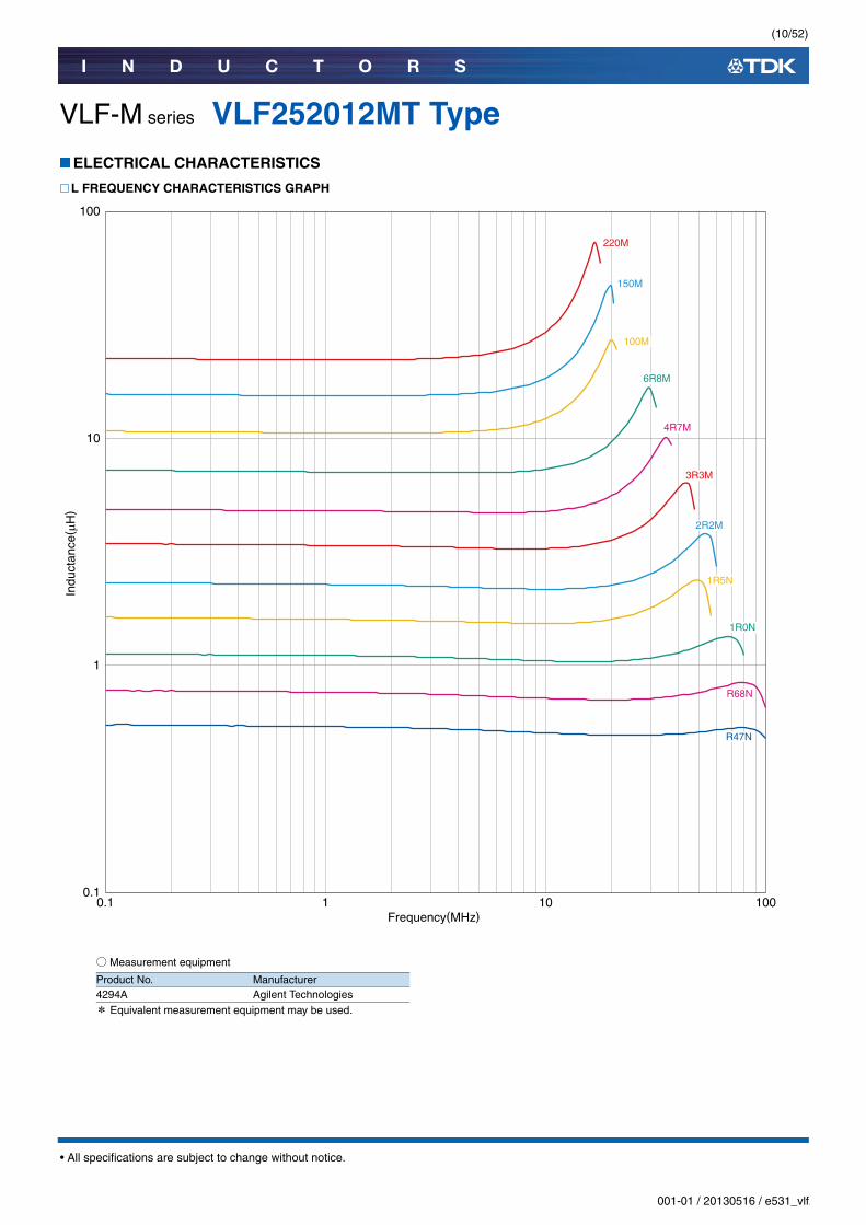
VLF-M series VLF252012MT TypeELECTRICAL CHARACTERISTICS
L FREQUENCY CHARACTERISTICS GRAPH
○Measurement equipment
* Equivalent measurement equipment may be used.
0.1
1
10
100
0.1 1 10 100
Indu
ctan
ce( µ
H)
Frequency(MHz)
3R3M
2R2M
1R5N
1R0N
R68N
R47N
100M
6R8M
4R7M
220M
150M
Product No. Manufacturer4294A Agilent Technologies

(11/52)
I N D U C T O R S
001-01 / 20130516 / e531_vlf.fm
• All specifications are subject to change without notice.
VLF-M series VLF252012MT TypeELECTRICAL CHARACTERISTICS
INDUCTANCE VS. DC BIAS CHARACTERISTICS GRAPH
○Measurement equipment
* Equivalent measurement equipment may be used.
0 0.5 1 1.5 2 2.5DC current(A)
Indu
ctan
ce( μ
H)
0
25
20
15
10
5
3R3M2R2M
1R5N 1R0N R68N
R47N
100M
6R8M
4R7M
220M
150M
Product No. Manufacturer4285A+42841A+42842C Agilent Technologies

(12/52)
I N D U C T O R S
001-01 / 20130516 / e531_vlf.fm
• All specifications are subject to change without notice.
VLF-M series
VLF252015MT TypeSHAPE & DIMENSIONS
RECOMMENDED LAND PATTERN
2.5±
0.2
1.5m
ax.
2.0±0.2
(0.55)
( 0.8
5)
(0.55)(0.6)
Dimensions in mm
Dimensions in mm0.75 0.75
1.3
0.6
(13/52)
I N D U C T O R S
001-01 / 20130516 / e531_vlf.fm
• All specifications are subject to change without notice.
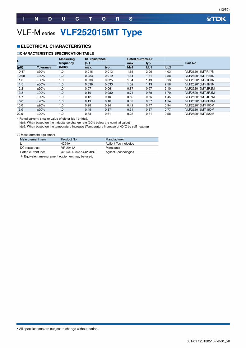
VLF-M series VLF252015MT TypeELECTRICAL CHARACTERISTICS
CHARACTERISTICS SPECIFICATION TABLE
Rated current: smaller value of either Idc1 or Idc2.Idc1: When based on the inductance change rate (30% below the nominal value)Idc2: When based on the temperature increase (Temperature increase of 40°C by self heating)
○Measurement equipment
* Equivalent measurement equipment may be used.
L Measuring frequency(MHz)
DC resistance ( )
Rated current(A)
Part No.max. typ.(µH) Tolerance max. typ. Idc1 Idc1 Idc2
0.47 ±30% 1.0 0.016 0.013 1.85 2.06 4.03 VLF252015MT-R47N0.68 ±30% 1.0 0.023 0.019 1.54 1.71 3.38 VLF252015MT-R68N1.0 ±30% 1.0 0.030 0.025 1.34 1.49 3.13 VLF252015MT-1R0N1.5 ±30% 1.0 0.039 0.033 1.02 1.13 2.58 VLF252015MT-1R5N2.2 ±20% 1.0 0.07 0.06 0.87 0.97 2.10 VLF252015MT-2R2M3.3 ±20% 1.0 0.10 0.080 0.71 0.79 1.70 VLF252015MT-3R3M4.7 ±20% 1.0 0.12 0.10 0.59 0.66 1.45 VLF252015MT-4R7M6.8 ±20% 1.0 0.19 0.16 0.52 0.57 1.14 VLF252015MT-6R8M
10.0 ±20% 1.0 0.28 0.24 0.42 0.47 0.94 VLF252015MT-100M15.0 ±20% 1.0 0.45 0.37 0.34 0.37 0.77 VLF252015MT-150M22.0 ±20% 1.0 0.73 0.61 0.28 0.31 0.58 VLF252015MT-220M
Measurement item Product No. ManufacturerL 4294A Agilent TechnologiesDC resistance VP-2941A PanasonicRated current Idc1 4285A+42841A+42842C Agilent Technologies
(14/52)
I N D U C T O R S
001-01 / 20130516 / e531_vlf.fm
• All specifications are subject to change without notice.
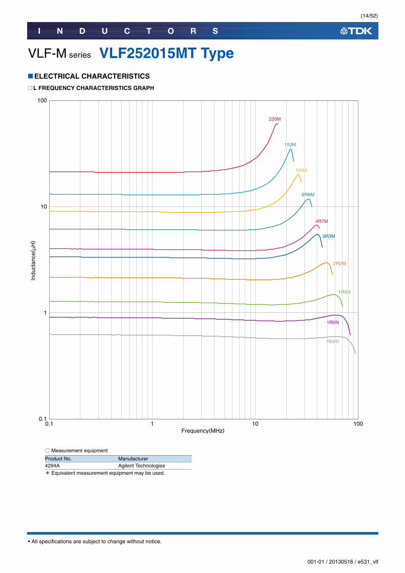
VLF-M series VLF252015MT TypeELECTRICAL CHARACTERISTICS
L FREQUENCY CHARACTERISTICS GRAPH
○Measurement equipment
* Equivalent measurement equipment may be used.
0.1
1
10
100
0.1 1 10 100
Indu
ctan
ce( µ
H)
Frequency(MHz)
100M
6R8M
4R7M
3R3M
220M
150M
2R2M
1R5N
1R0N
R68N
Product No. Manufacturer4294A Agilent Technologies
(15/52)
I N D U C T O R S
001-01 / 20130516 / e531_vlf.fm
• All specifications are subject to change without notice.
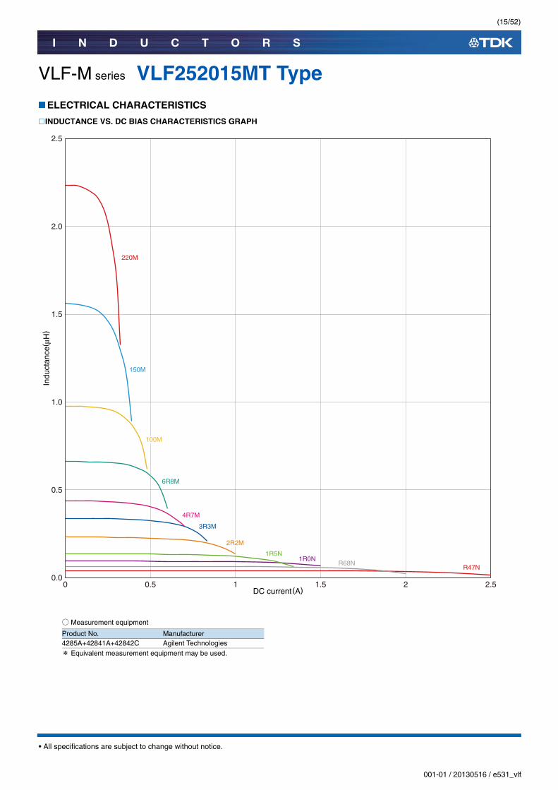
VLF-M series VLF252015MT TypeELECTRICAL CHARACTERISTICS
INDUCTANCE VS. DC BIAS CHARACTERISTICS GRAPH
○Measurement equipment
* Equivalent measurement equipment may be used.
0.0
2.5
2.0
1.5
1.0
0.5
Indu
ctan
ce( μ
H)
0 0.5 1 1.5 2 2.5DC current(A)
3R3M
100M
6R8M
4R7M
220M
150M
2R2M
1R5N1R0N
R68NR47N
Product No. Manufacturer4285A+42841A+42842C Agilent Technologies

(16/52)
I N D U C T O R S
001-01 / 20130516 / e531_vlf.fm
• All specifications are subject to change without notice.
VLF-M series
VLF302510MT TypeSHAPE & DIMENSIONS
RECOMMENDED LAND PATTERN
(0.7) (0.7)(0.8)
3.0±
0.2
1.0m
ax.
2.5±0.2
( 1.0
)Dimensions in mm
Dimensions in mm0.9 0.90.8
1.45
(17/52)
I N D U C T O R S
001-01 / 20130516 / e531_vlf.fm
• All specifications are subject to change without notice.
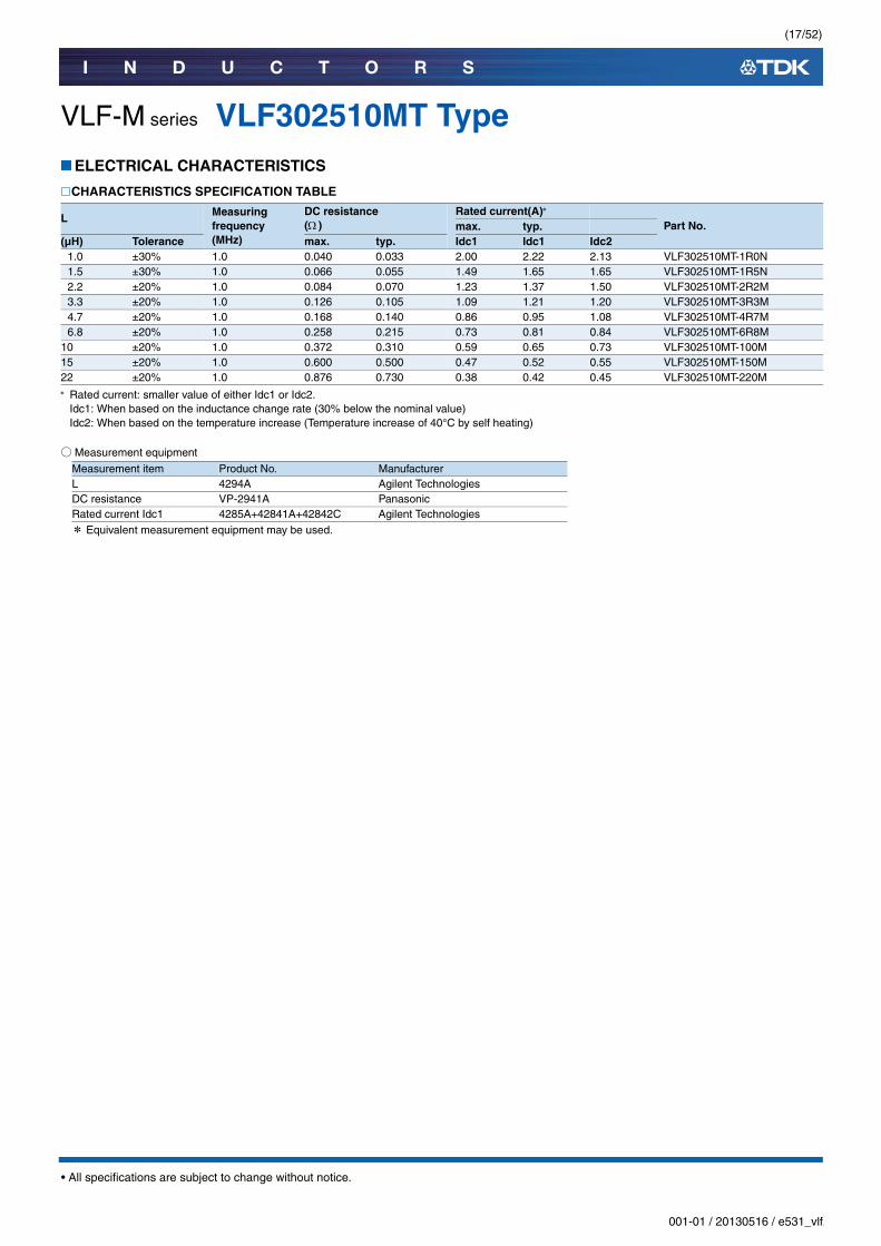
VLF-M series VLF302510MT TypeELECTRICAL CHARACTERISTICS
CHARACTERISTICS SPECIFICATION TABLE
Rated current: smaller value of either Idc1 or Idc2.Idc1: When based on the inductance change rate (30% below the nominal value)Idc2: When based on the temperature increase (Temperature increase of 40°C by self heating)
○Measurement equipment
* Equivalent measurement equipment may be used.
L Measuring frequency(MHz)
DC resistance ( )
Rated current(A)
Part No.max. typ.(µH) Tolerance max. typ. Idc1 Idc1 Idc2
1.0 ±30% 1.0 0.040 0.033 2.00 2.22 2.13 VLF302510MT-1R0N1.5 ±30% 1.0 0.066 0.055 1.49 1.65 1.65 VLF302510MT-1R5N2.2 ±20% 1.0 0.084 0.070 1.23 1.37 1.50 VLF302510MT-2R2M3.3 ±20% 1.0 0.126 0.105 1.09 1.21 1.20 VLF302510MT-3R3M4.7 ±20% 1.0 0.168 0.140 0.86 0.95 1.08 VLF302510MT-4R7M6.8 ±20% 1.0 0.258 0.215 0.73 0.81 0.84 VLF302510MT-6R8M
10 ±20% 1.0 0.372 0.310 0.59 0.65 0.73 VLF302510MT-100M15 ±20% 1.0 0.600 0.500 0.47 0.52 0.55 VLF302510MT-150M22 ±20% 1.0 0.876 0.730 0.38 0.42 0.45 VLF302510MT-220M
Measurement item Product No. ManufacturerL 4294A Agilent TechnologiesDC resistance VP-2941A PanasonicRated current Idc1 4285A+42841A+42842C Agilent Technologies
(18/52)
I N D U C T O R S
001-01 / 20130516 / e531_vlf.fm
• All specifications are subject to change without notice.
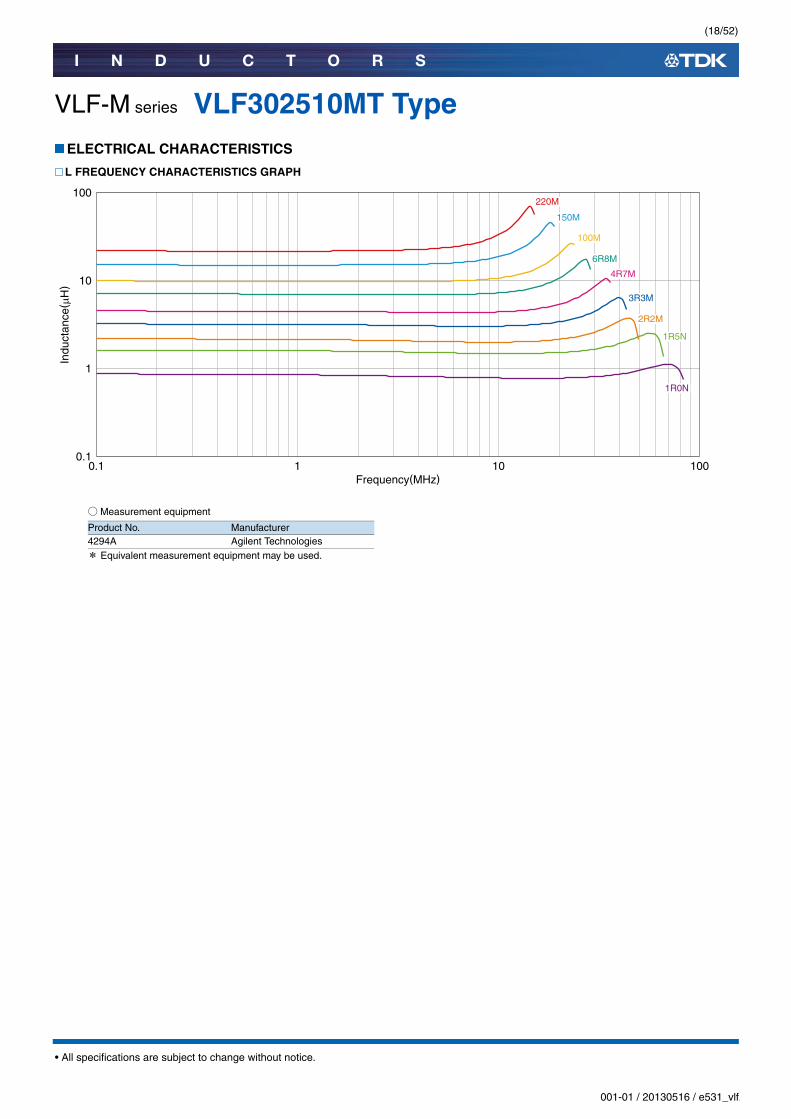
VLF-M series VLF302510MT TypeELECTRICAL CHARACTERISTICS
L FREQUENCY CHARACTERISTICS GRAPH
○Measurement equipment
* Equivalent measurement equipment may be used.
0.1
1
10
100
0.1 1 10 100
Indu
ctan
ce( µ
H)
Frequency(MHz)
3R3M
2R2M
1R5N
1R0N
100M
6R8M
4R7M
220M
150M
Product No. Manufacturer4294A Agilent Technologies
(19/52)
I N D U C T O R S
001-01 / 20130516 / e531_vlf.fm
• All specifications are subject to change without notice.
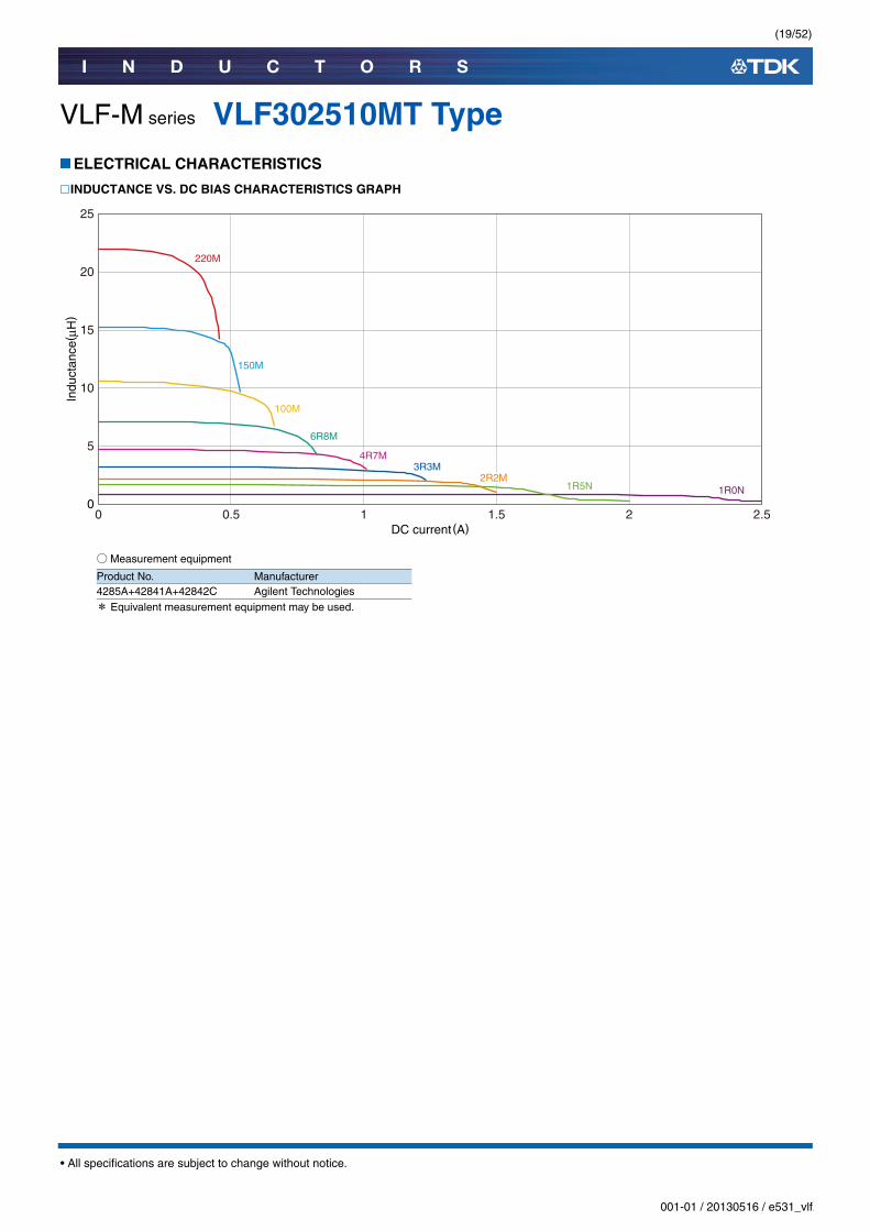
VLF-M series VLF302510MT TypeELECTRICAL CHARACTERISTICS
INDUCTANCE VS. DC BIAS CHARACTERISTICS GRAPH
○Measurement equipment
* Equivalent measurement equipment may be used.
0 0.5 1 1.5 2 2.5DC current(A)
0
5
10
15
20
25
Indu
ctan
ce( μ
H)
100M
6R8M
4R7M3R3M
2R2M1R5N 1R0N
220M
150M
Product No. Manufacturer4285A+42841A+42842C Agilent Technologies

(20/52)
I N D U C T O R S
001-01 / 20130516 / e531_vlf.fm
• All specifications are subject to change without notice.
VLF-M series
VLF302512MT TypeSHAPE & DIMENSIONS
RECOMMENDED LAND PATTERN
(0.7) (0.7)(0.8)
3.0±
0.2
1.2m
ax.
2.5±0.2
( 1.0
)Dimensions in mm
Dimensions in mm0.9 0.90.8
1.45

(21/52)
I N D U C T O R S
001-01 / 20130516 / e531_vlf.fm
• All specifications are subject to change without notice.
VLF-M series VLF302512MT TypeELECTRICAL CHARACTERISTICS
CHARACTERISTICS SPECIFICATION TABLE
Rated current: smaller value of either Idc1 or Idc2.Idc1: When based on the inductance change rate (30% below the nominal value)Idc2: When based on the temperature increase (Temperature increase of 40°C by self heating)
○Measurement equipment
* Equivalent measurement equipment may be used.
L Measuring frequency(MHz)
DC resistance ( )
Rated current(A)
Part No.max. typ.(µH) tolerance max. typ. Idc1 Idc1 Idc2
1.0 ±30% 1.0 0.037 0.031 1.91 2.12 2.77 VLF302512MT-1R0N1.5 ±30% 1.0 0.044 0.037 1.67 1.85 2.54 VLF302512MT-1R5N2.2 ±20% 1.0 0.066 0.055 1.26 1.40 1.95 VLF302512MT-2R2M3.3 ±20% 1.0 0.108 0.090 1.08 1.20 1.63 VLF302512MT-3R3M4.7 ±20% 1.0 0.136 0.113 0.97 1.08 1.42 VLF302512MT-4R7M6.8 ±20% 1.0 0.194 0.162 0.78 0.84 1.21 VLF302512MT-6R8M
10 ±20% 1.0 0.299 0.249 0.62 0.69 0.95 VLF302512MT-100M15 ±20% 1.0 0.448 0.373 0.51 0.57 0.80 VLF302512MT-150M22 ±20% 1.0 0.700 0.583 0.43 0.47 0.64 VLF302512MT-220M
Measurement item Product No. ManufacturerL 4294A Agilent TechnologiesDC resistance VP-2941A PanasonicRated current Idc1 4285A+42841A+42842C Agilent Technologies

(22/52)
I N D U C T O R S
001-01 / 20130516 / e531_vlf.fm
• All specifications are subject to change without notice.
VLF-M series VLF302512MT TypeELECTRICAL CHARACTERISTICS
L FREQUENCY CHARACTERISTICS GRAPH
○Measurement equipment
* Equivalent measurement equipment may be used.
0.1
1
10
100
0.1 1 10 100
Indu
ctan
ce( µ
H)
Frequency(MHz)
100M
6R8M
4R7M
3R3M
2R2M
1R5N
1R0N
220M
150M
Product No. Manufacturer4294A Agilent Technologies

(23/52)
I N D U C T O R S
001-01 / 20130516 / e531_vlf.fm
• All specifications are subject to change without notice.
VLF-M series VLF302512MT TypeELECTRICAL CHARACTERISTICS
INDUCTANCE VS. DC BIAS CHARACTERISTICS GRAPH
○Measurement equipment
* Equivalent measurement equipment may be used.
0 0.5 1 1.5 2 2.5DC current(A)
0
5
10
15
20
25
Indu
ctan
ce( μ
H)
100M
6R8M
4R7M3R3M
2R2M1R5N
1R0N
220M
150M
Product No. Manufacturer4285A+42841A+42842C Agilent Technologies
(24/52)
I N D U C T O R S
001-01 / 20130516 / e531_vlf.fm
• All specifications are subject to change without notice.
VLF-M series
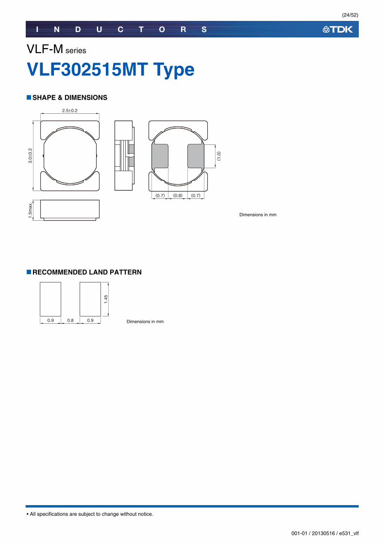
VLF302515MT TypeSHAPE & DIMENSIONS
RECOMMENDED LAND PATTERN
(0.7) (0.7)(0.8)
3.0±
0.2
1.5m
ax.
2.5±0.2
( 1.0
)Dimensions in mm
Dimensions in mm0.9 0.90.8
1.45
(25/52)
I N D U C T O R S
001-01 / 20130516 / e531_vlf.fm
• All specifications are subject to change without notice.
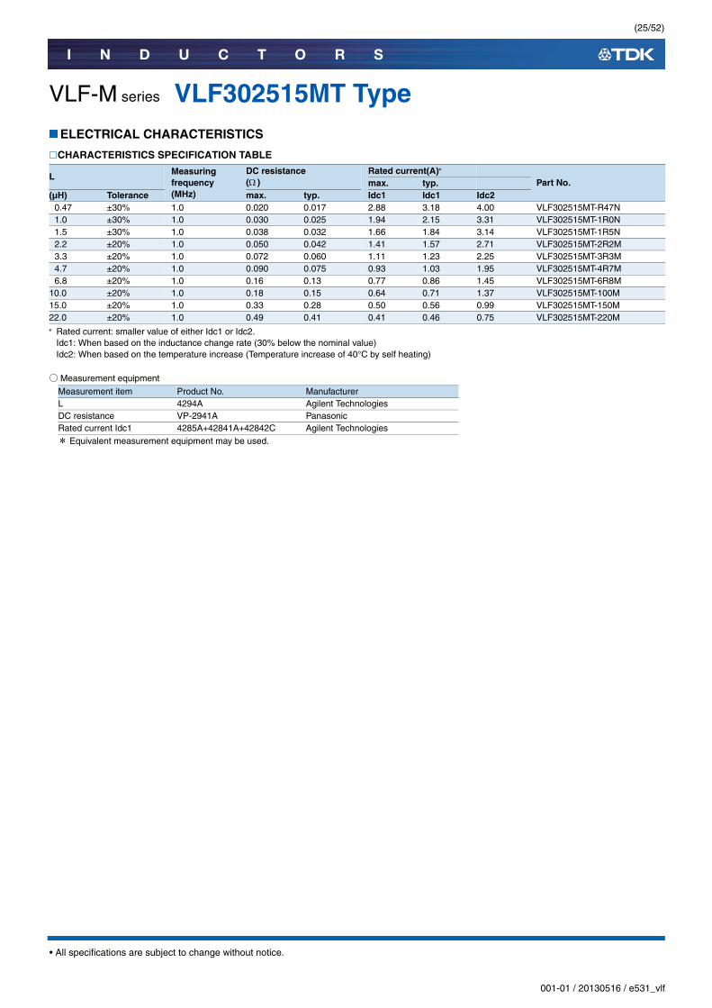
VLF-M series VLF302515MT TypeELECTRICAL CHARACTERISTICS
CHARACTERISTICS SPECIFICATION TABLE
Rated current: smaller value of either Idc1 or Idc2.Idc1: When based on the inductance change rate (30% below the nominal value)Idc2: When based on the temperature increase (Temperature increase of 40°C by self heating)
○Measurement equipment
* Equivalent measurement equipment may be used.
L Measuring frequency(MHz)
DC resistance ( )
Rated current(A)
Part No.max. typ.(µH) Tolerance max. typ. Idc1 Idc1 Idc2
0.47 ±30% 1.0 0.020 0.017 2.88 3.18 4.00 VLF302515MT-R47N1.0 ±30% 1.0 0.030 0.025 1.94 2.15 3.31 VLF302515MT-1R0N1.5 ±30% 1.0 0.038 0.032 1.66 1.84 3.14 VLF302515MT-1R5N2.2 ±20% 1.0 0.050 0.042 1.41 1.57 2.71 VLF302515MT-2R2M3.3 ±20% 1.0 0.072 0.060 1.11 1.23 2.25 VLF302515MT-3R3M4.7 ±20% 1.0 0.090 0.075 0.93 1.03 1.95 VLF302515MT-4R7M6.8 ±20% 1.0 0.16 0.13 0.77 0.86 1.45 VLF302515MT-6R8M
10.0 ±20% 1.0 0.18 0.15 0.64 0.71 1.37 VLF302515MT-100M15.0 ±20% 1.0 0.33 0.28 0.50 0.56 0.99 VLF302515MT-150M22.0 ±20% 1.0 0.49 0.41 0.41 0.46 0.75 VLF302515MT-220M
Measurement item Product No. ManufacturerL 4294A Agilent TechnologiesDC resistance VP-2941A PanasonicRated current Idc1 4285A+42841A+42842C Agilent Technologies

(26/52)
I N D U C T O R S
001-01 / 20130516 / e531_vlf.fm
• All specifications are subject to change without notice.
VLF-M series VLF302515MT TypeELECTRICAL CHARACTERISTICS
L FREQUENCY CHARACTERISTICS GRAPH
○Measurement equipment
* Equivalent measurement equipment may be used.
0.1
1
10
100
0.1 1 10 100
Indu
ctan
ce( µ
H)
Frequency(MHz)
100M
6R8M
4R7M
3R3M
2R2M
1R5N
1R0N
220M
150M
Product No. Manufacturer4294A Agilent Technologies
(27/52)
I N D U C T O R S
001-01 / 20130516 / e531_vlf.fm
• All specifications are subject to change without notice.
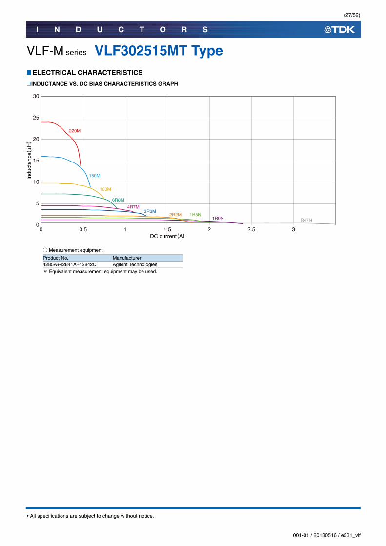
VLF-M series VLF302515MT TypeELECTRICAL CHARACTERISTICS
INDUCTANCE VS. DC BIAS CHARACTERISTICS GRAPH
○Measurement equipment
* Equivalent measurement equipment may be used.
0
30
20
10
15
25
5
Indu
ctan
ce( μ
H)
0 1 2 30.5 1.5 2.5DC current(A)
3R3M2R2M 1R5N
1R0N
100M
6R8M
4R7M
220M
150M
R47N
Product No. Manufacturer4285A+42841A+42842C Agilent Technologies
(28/52)
I N D U C T O R S
001-01 / 20130516 / e531_vlf.fm
• All specifications are subject to change without notice.
VLF-M series
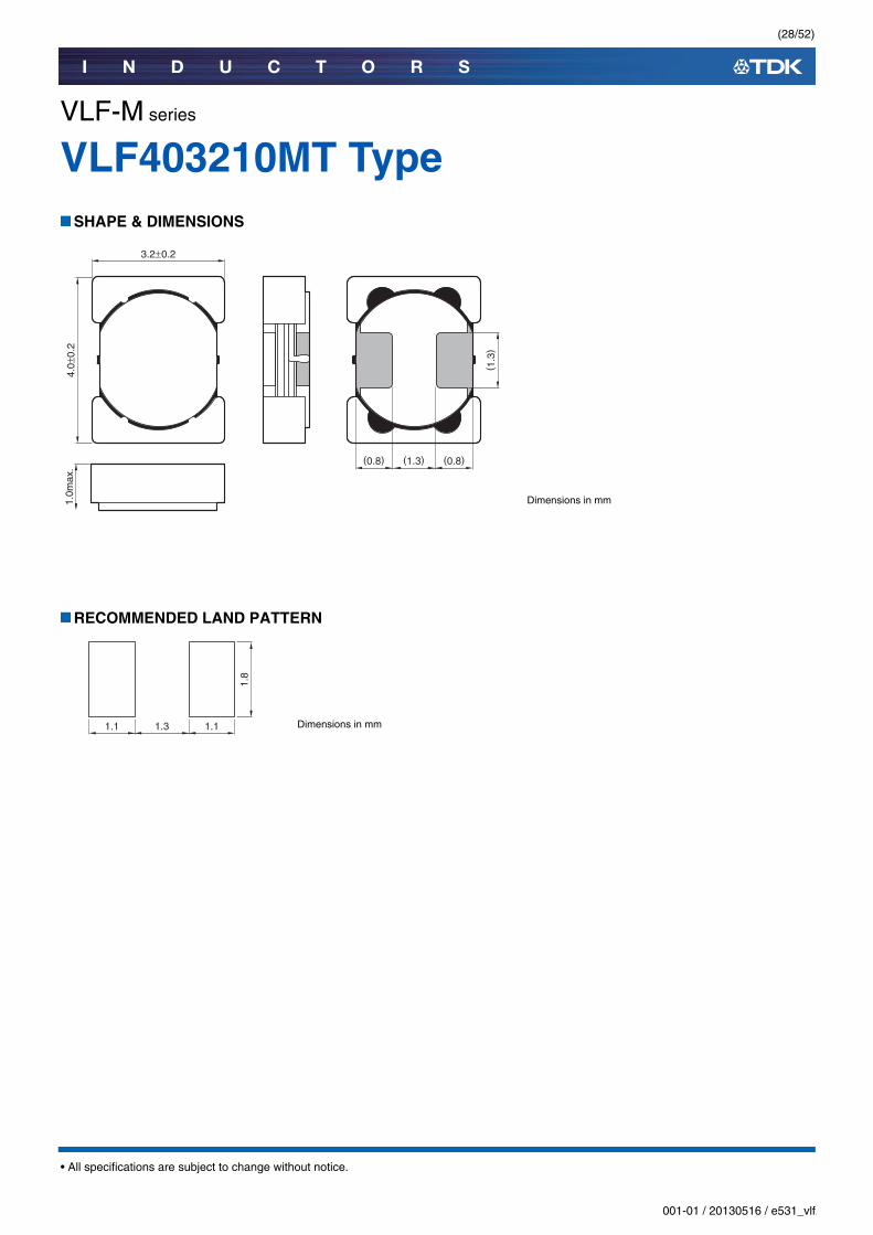
VLF403210MT TypeSHAPE & DIMENSIONS
RECOMMENDED LAND PATTERN
(0.8) (0.8)(1.3)
4.0±
0.2
1.0m
ax.
3.2±0.2
( 1.3
)Dimensions in mm
Dimensions in mm1.1 1.11.3
1.8

(29/52)
I N D U C T O R S
001-01 / 20130516 / e531_vlf.fm
• All specifications are subject to change without notice.
VLF-M series VLF403210MT TypeELECTRICAL CHARACTERISTICS
CHARACTERISTICS SPECIFICATION TABLE
Rated current: smaller value of either Idc1 or Idc2.Idc1: When based on the inductance change rate (30% below the nominal value)Idc2: When based on the temperature increase (Temperature increase of 40°C by self heating)
○Measurement equipment
* Equivalent measurement equipment may be used.
L Measuring frequency(MHz)
DC resistance ( )
Rated current(A)
Part No.max. typ.(µH) tolerance max. typ. Idc1 Idc1 Idc2
1.0 ±30% 1.0 0.032 0.026 2.23 2.48 3.44 VLF403210MT-1R0N1.5 ±30% 1.0 0.043 0.036 1.85 2.06 2.96 VLF403210MT-1R5N2.2 ±20% 1.0 0.066 0.055 1.59 1.77 2.33 VLF403210MT-2R2M3.3 ±20% 1.0 0.098 0.082 1.19 1.32 1.95 VLF403210MT-3R3M4.7 ±20% 1.0 0.14 0.12 1.09 1.21 1.61 VLF403210MT-4R7M6.8 ±20% 1.0 0.22 0.18 0.84 0.93 1.24 VLF403210MT-6R8M
10.0 ±20% 1.0 0.31 0.26 0.70 0.78 1.04 VLF403210MT-100M15.0 ±20% 1.0 0.49 0.40 0.59 0.66 0.83 VLF403210MT-150M22.0 ±20% 1.0 0.72 0.60 0.46 0.51 0.68 VLF403210MT-220M
Measurement item Product No. ManufacturerL 4294A Agilent TechnologiesDC resistance VP-2941A PanasonicRated current Idc1 4285A+42841A+42842C Agilent Technologies

(30/52)
I N D U C T O R S
001-01 / 20130516 / e531_vlf.fm
• All specifications are subject to change without notice.
VLF-M series VLF403210MT TypeELECTRICAL CHARACTERISTICS
L FREQUENCY CHARACTERISTICS GRAPH
○Measurement equipment
* Equivalent measurement equipment may be used.
0.1
1
10
100
0.1 1 10 100
Indu
ctan
ce( µ
H)
Frequency(MHz)
100M
6R8M
4R7M
3R3M
2R2M
1R5N
1R0N
220M
150M
Product No. Manufacturer4294A Agilent Technologies

(31/52)
I N D U C T O R S
001-01 / 20130516 / e531_vlf.fm
• All specifications are subject to change without notice.
VLF-M series VLF403210MT TypeELECTRICAL CHARACTERISTICS
INDUCTANCE VS. DC BIAS CHARACTERISTICS GRAPH
○Measurement equipment
* Equivalent measurement equipment may be used.
0 0.5 1 1.5 2 32.5DC current(A)
0
25
20
15
10
5
Indu
ctan
ce( μ
H)
100M
6R8M
4R7M3R3M 2R2M
1R5N 1R0N
220M
150M
Product No. Manufacturer4285A+42841A+42842C Agilent Technologies
(32/52)
I N D U C T O R S
001-01 / 20130516 / e531_vlf.fm
• All specifications are subject to change without notice.
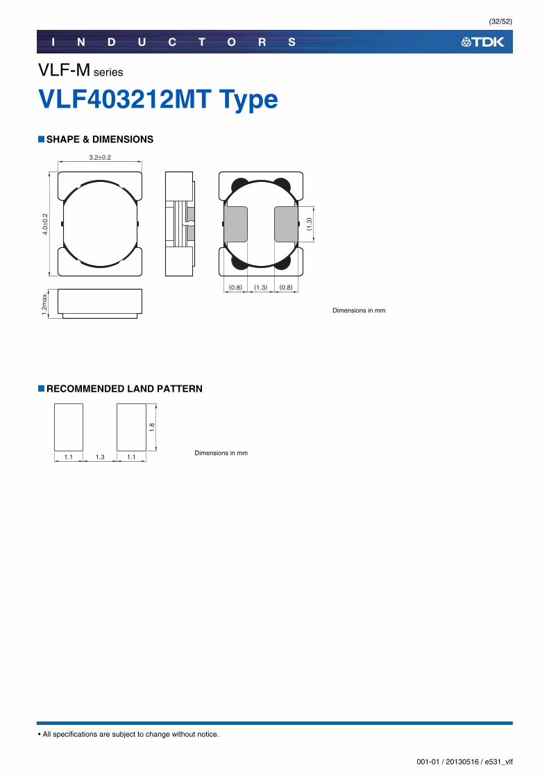
VLF-M series
VLF403212MT TypeSHAPE & DIMENSIONS
RECOMMENDED LAND PATTERN
1.2m
ax.
(0.8) (0.8)(1.3)
4.0±
0.2
3.2±0.2
( 1.3
)Dimensions in mm
Dimensions in mm1.1 1.11.3
1.8
(33/52)
I N D U C T O R S
001-01 / 20130516 / e531_vlf.fm
• All specifications are subject to change without notice.
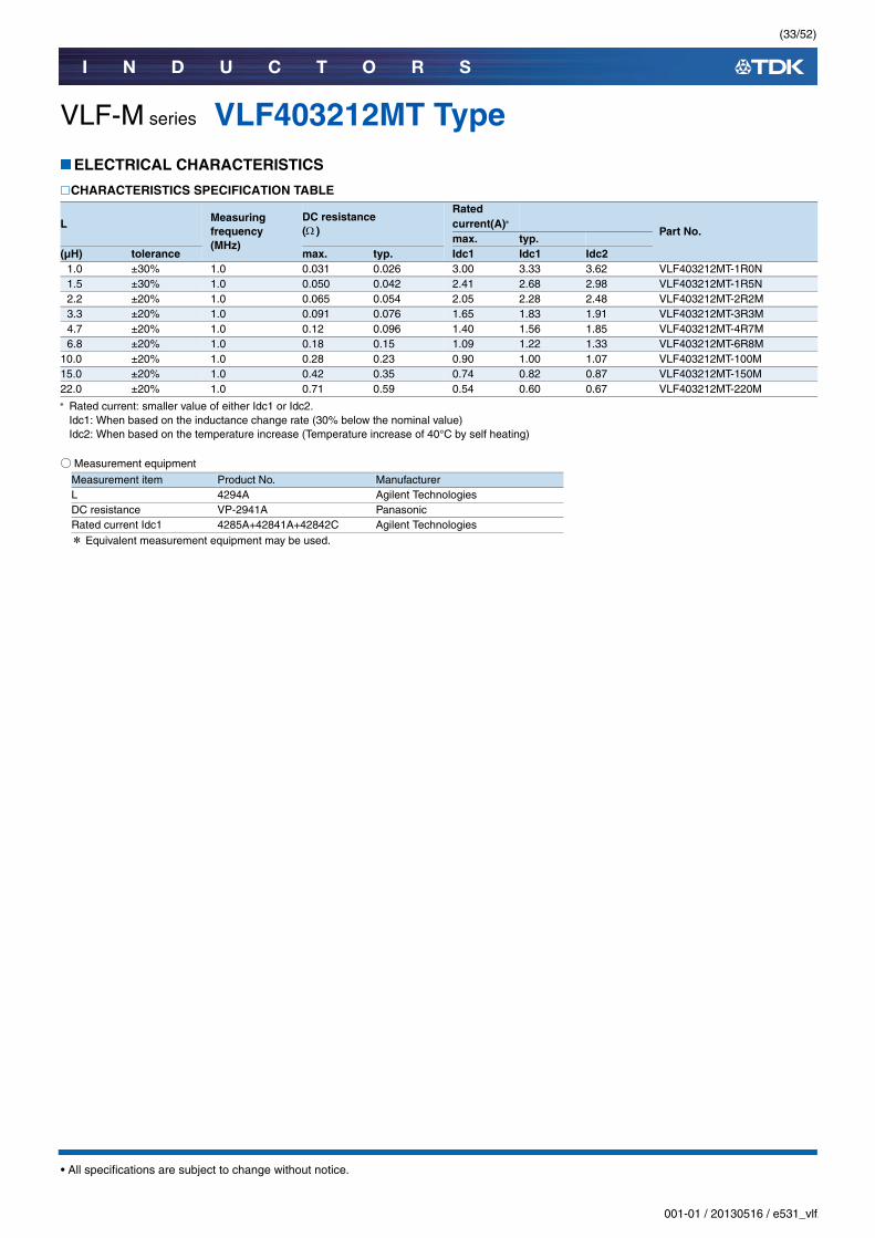
VLF-M series VLF403212MT TypeELECTRICAL CHARACTERISTICS
CHARACTERISTICS SPECIFICATION TABLE
Rated current: smaller value of either Idc1 or Idc2.Idc1: When based on the inductance change rate (30% below the nominal value)Idc2: When based on the temperature increase (Temperature increase of 40°C by self heating)
○Measurement equipment
* Equivalent measurement equipment may be used.
L Measuring frequency(MHz)
DC resistance ( )
Rated current(A)
Part No.max. typ.
(µH) tolerance max. typ. Idc1 Idc1 Idc21.0 ±30% 1.0 0.031 0.026 3.00 3.33 3.62 VLF403212MT-1R0N1.5 ±30% 1.0 0.050 0.042 2.41 2.68 2.98 VLF403212MT-1R5N2.2 ±20% 1.0 0.065 0.054 2.05 2.28 2.48 VLF403212MT-2R2M3.3 ±20% 1.0 0.091 0.076 1.65 1.83 1.91 VLF403212MT-3R3M4.7 ±20% 1.0 0.12 0.096 1.40 1.56 1.85 VLF403212MT-4R7M6.8 ±20% 1.0 0.18 0.15 1.09 1.22 1.33 VLF403212MT-6R8M
10.0 ±20% 1.0 0.28 0.23 0.90 1.00 1.07 VLF403212MT-100M15.0 ±20% 1.0 0.42 0.35 0.74 0.82 0.87 VLF403212MT-150M22.0 ±20% 1.0 0.71 0.59 0.54 0.60 0.67 VLF403212MT-220M
Measurement item Product No. ManufacturerL 4294A Agilent TechnologiesDC resistance VP-2941A PanasonicRated current Idc1 4285A+42841A+42842C Agilent Technologies

(34/52)
I N D U C T O R S
001-01 / 20130516 / e531_vlf.fm
• All specifications are subject to change without notice.
VLF-M series VLF403212MT TypeELECTRICAL CHARACTERISTICS
L FREQUENCY CHARACTERISTICS GRAPH
○Measurement equipment
* Equivalent measurement equipment may be used.
0.1
1
10
100
0.1 1 10 100
Indu
ctan
ce( µ
H)
Frequency(MHz)
100M
6R8M
4R7M
3R3M
2R2M
1R5N
1R0N
220M
150M
Product No. Manufacturer4294A Agilent Technologies

(35/52)
I N D U C T O R S
001-01 / 20130516 / e531_vlf.fm
• All specifications are subject to change without notice.
VLF-M series VLF403212MT TypeELECTRICAL CHARACTERISTICS
INDUCTANCE VS. DC BIAS CHARACTERISTICS GRAPH
○Measurement equipment
* Equivalent measurement equipment may be used.
0 1 2 3 40
25
20
15
10
5
DC current(A)
Indu
ctan
ce( μ
H)
100M
6R8M
4R7M3R3M 2R2M
1R5N1R0N
220M
150M
Product No. Manufacturer4285A+42841A+42842C Agilent Technologies

(36/52)
I N D U C T O R S
001-01 / 20130516 / e531_vlf.fm
• All specifications are subject to change without notice.
VLF-M series
VLF403215MT TypeSHAPE & DIMENSIONS
RECOMMENDED LAND PATTERN
1.5m
ax.
(0.8) (0.8)(1.3)
4.0±
0.2
3.2±0.2
( 1.3
)Dimensions in mm
Dimensions in mm1.1 1.11.3
1.8

(37/52)
I N D U C T O R S
001-01 / 20130516 / e531_vlf.fm
• All specifications are subject to change without notice.
VLF-M series VLF403215MT TypeELECTRICAL CHARACTERISTICS
CHARACTERISTICS SPECIFICATION TABLE
Rated current: smaller value of either Idc1 or Idc2.Idc1: When based on the inductance change rate (30% below the nominal value)Idc2: When based on the temperature increase (Temperature increase of 40°C by self heating)
○Measurement equipment
* Equivalent measurement equipment may be used.
L Measuring frequency(MHz)
DC resistance ( )
Rated current(A)
Part No.max. typ.(µH) Tolerance max. typ. Idc1 Idc1 Idc2
1.0 ±30% 1.0 0.031 0.026 3.01 3.34 3.56 VLF403215MT-1R0N1.5 ±30% 1.0 0.036 0.030 2.46 2.73 3.38 VLF403215MT-1R5N2.2 ±20% 1.0 0.043 0.036 2.03 2.25 3.14 VLF403215MT-2R2M3.3 ±20% 1.0 0.062 0.051 1.65 1.83 2.65 VLF403215MT-3R3M4.7 ±20% 1.0 0.087 0.073 1.39 1.54 2.13 VLF403215MT-4R7M6.8 ±20% 1.0 0.13 0.11 1.14 1.27 1.68 VLF403215MT-6R8M
10.0 ±20% 1.0 0.18 0.15 1.00 1.09 1.44 VLF403215MT-100M15.0 ±20% 1.0 0.26 0.22 0.78 0.87 1.19 VLF403215MT-150M22.0 ±20% 1.0 0.38 0.32 0.65 0.72 0.95 VLF403215MT-220M
Measurement item Product No. ManufacturerL 4294A Agilent TechnologiesDC resistance VP-2941A PanasonicRated current Idc1 4285A+42841A+42842C Agilent Technologies
(38/52)
I N D U C T O R S
001-01 / 20130516 / e531_vlf.fm
• All specifications are subject to change without notice.
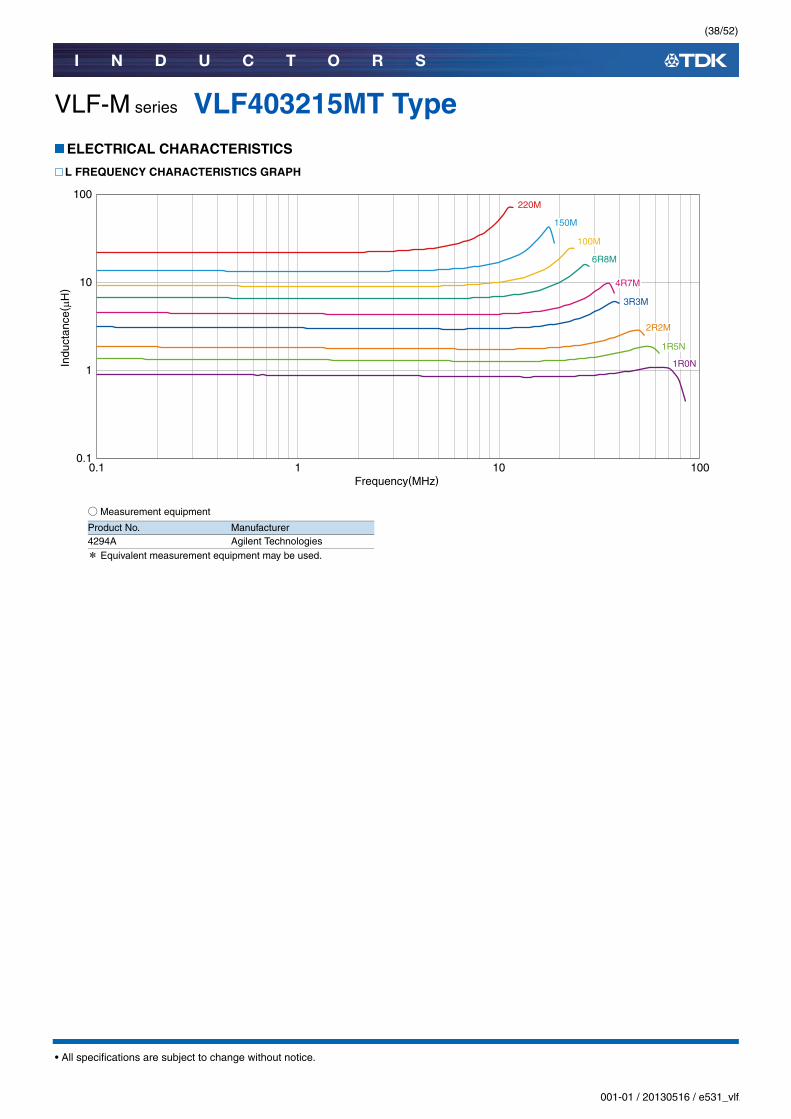
VLF-M series VLF403215MT TypeELECTRICAL CHARACTERISTICS
L FREQUENCY CHARACTERISTICS GRAPH
○Measurement equipment
* Equivalent measurement equipment may be used.
0.1
1
10
100
0.1 1 10 100
Indu
ctan
ce( µ
H)
Frequency(MHz)
100M
6R8M
4R7M
3R3M
2R2M
1R5N
1R0N
220M
150M
Product No. Manufacturer4294A Agilent Technologies

(39/52)
I N D U C T O R S
001-01 / 20130516 / e531_vlf.fm
• All specifications are subject to change without notice.
VLF-M series VLF403215MT TypeELECTRICAL CHARACTERISTICS
INDUCTANCE VS. DC BIAS CHARACTERISTICS GRAPH
○Measurement equipment
* Equivalent measurement equipment may be used.
0
25
20
15
10
5
0 1 2 3 4DC current(A)
Indu
ctan
ce( μ
H)
100M
6R8M
4R7M3R3M
2R2M 1R5N1R0N
220M
150M
Product No. Manufacturer4285A+42841A+42842C Agilent Technologies
(40/52)
I N D U C T O R S
001-01 / 20130516 / e531_vlf.fm
• All specifications are subject to change without notice.
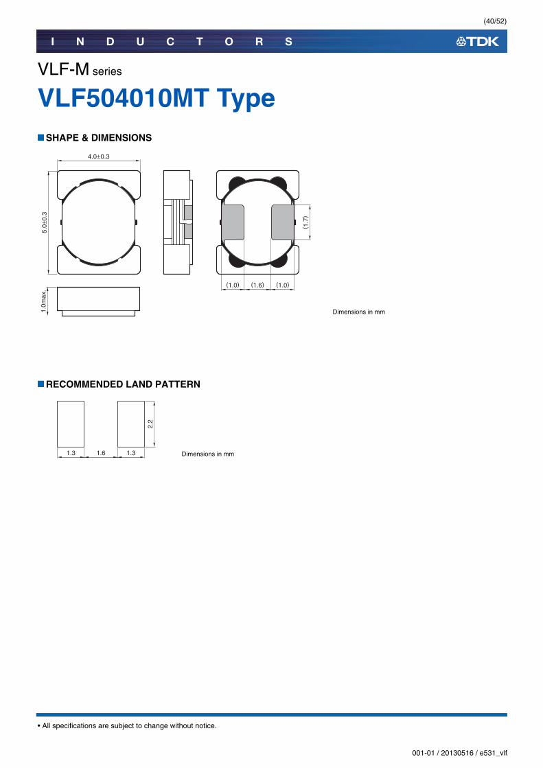
VLF-M series
VLF504010MT TypeSHAPE & DIMENSIONS
RECOMMENDED LAND PATTERN
(1.0) (1.0)(1.6)
5.0±
0.3
1.0m
ax.
4.0±0.3
( 1.7
)Dimensions in mm
Dimensions in mm1.3 1.3
2.2
1.6

(41/52)
I N D U C T O R S
001-01 / 20130516 / e531_vlf.fm
• All specifications are subject to change without notice.
VLF-M series VLF504010MT TypeELECTRICAL CHARACTERISTICS
CHARACTERISTICS SPECIFICATION TABLE
Rated current: smaller value of either Idc1 or Idc2.Idc1: When based on the inductance change rate (30% below the nominal value)Idc2: When based on the temperature increase (Temperature increase of 40°C by self heating)
○Measurement equipment
* Equivalent measurement equipment may be used.
L Measuring frequency(MHz)
DC resistance ( )
Rated current(A)
Part No.max. typ.(µH) tolerance max. typ. Idc1 Idc1 Idc2
0.68 ±30% 1.0 0.030 0.025 3.40 3.78 3.71 VLF504010MT-R68N1.0 ±30% 1.0 0.037 0.031 2.66 2.95 3.08 VLF504010MT-1R0N1.5 ±30% 1.0 0.044 0.037 2.30 2.56 2.86 VLF504010MT-1R5N2.2 ±20% 1.0 0.054 0.045 1.92 2.14 2.65 VLF504010MT-2R2M3.3 ±20% 1.0 0.091 0.076 1.58 1.75 2.10 VLF504010MT-3R3M4.7 ±20% 1.0 0.12 0.10 1.32 1.47 1.77 VLF504010MT-4R7M6.8 ±20% 1.0 0.19 0.16 1.09 1.21 1.40 VLF504010MT-6R8M
10.0 ±20% 1.0 0.25 0.21 0.90 1.00 1.21 VLF504010MT-100M15.0 ±20% 1.0 0.40 0.33 0.74 0.83 0.98 VLF504010MT-150M22.0 ±20% 1.0 0.60 0.50 0.61 0.68 0.78 VLF504010MT-220M
Measurement item Product No. ManufacturerL 4294A Agilent TechnologiesDC resistance VP-2941A PanasonicRated current Idc1 4285A+42841A+42842C Agilent Technologies
(42/52)
I N D U C T O R S
001-01 / 20130516 / e531_vlf.fm
• All specifications are subject to change without notice.
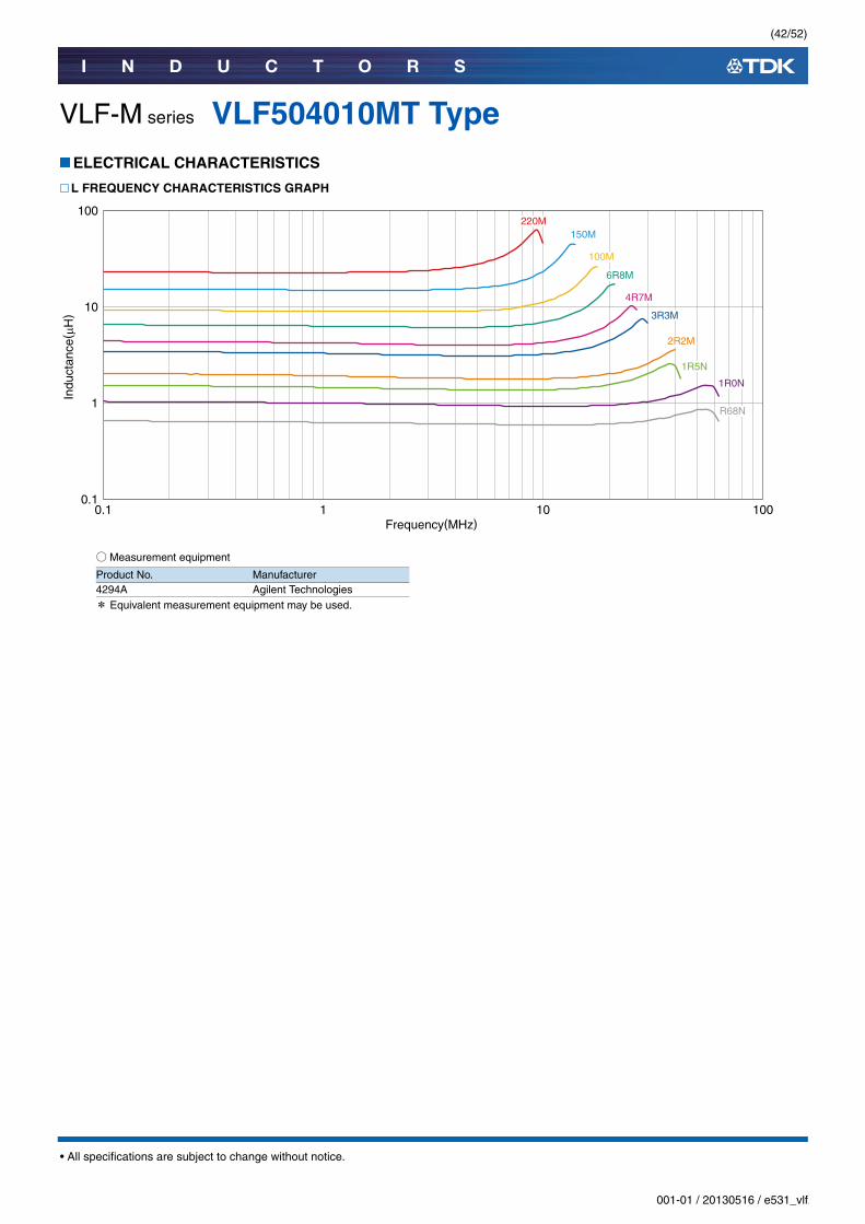
VLF-M series VLF504010MT TypeELECTRICAL CHARACTERISTICS
L FREQUENCY CHARACTERISTICS GRAPH
○Measurement equipment
* Equivalent measurement equipment may be used.
0.1
1
10
100
0.1 1 10 100
Indu
ctan
ce( µ
H)
Frequency(MHz)
3R3M
2R2M
1R5N
1R0N
R68N
100M
6R8M
4R7M
220M150M
Product No. Manufacturer4294A Agilent Technologies

(43/52)
I N D U C T O R S
001-01 / 20130516 / e531_vlf.fm
• All specifications are subject to change without notice.
VLF-M series VLF504010MT TypeELECTRICAL CHARACTERISTICS
INDUCTANCE VS. DC BIAS CHARACTERISTICS GRAPH
○Measurement equipment
* Equivalent measurement equipment may be used.
0 1 2 3 4DC current(A)
0
25
20
15
10
5
Indu
ctan
ce( μ
H)
3R3M2R2M 1R5N 1R0N R68N
100M
6R8M
4R7M
220M
150M
Product No. Manufacturer4285A+42841A+42842C Agilent Technologies

(44/52)
I N D U C T O R S
001-01 / 20130516 / e531_vlf.fm
• All specifications are subject to change without notice.
VLF-M series
VLF504012MT TypeSHAPE & DIMENSIONS
RECOMMENDED LAND PATTERN
(1.0) (1.0)(1.6)
5.0±
0.3
1.2m
ax.
4.0±0.2
( 1.7
)Dimensions in mm
Dimensions in mm1.3 1.3
2.2
1.6
(45/52)
I N D U C T O R S
001-01 / 20130516 / e531_vlf.fm
• All specifications are subject to change without notice.
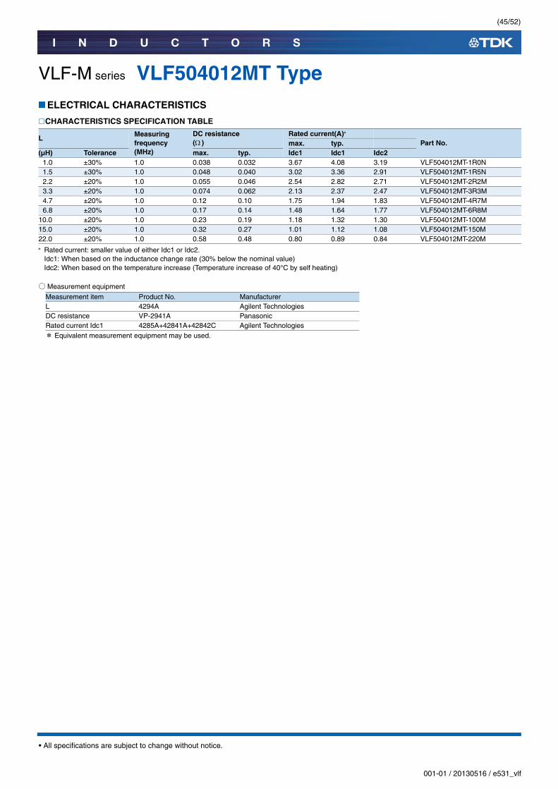
VLF-M series VLF504012MT TypeELECTRICAL CHARACTERISTICS
CHARACTERISTICS SPECIFICATION TABLE
Rated current: smaller value of either Idc1 or Idc2.Idc1: When based on the inductance change rate (30% below the nominal value)Idc2: When based on the temperature increase (Temperature increase of 40°C by self heating)
○Measurement equipment
* Equivalent measurement equipment may be used.
L Measuring frequency(MHz)
DC resistance ( )
Rated current(A)
Part No.max. typ.(µH) Tolerance max. typ. Idc1 Idc1 Idc2
1.0 ±30% 1.0 0.038 0.032 3.67 4.08 3.19 VLF504012MT-1R0N1.5 ±30% 1.0 0.048 0.040 3.02 3.36 2.91 VLF504012MT-1R5N2.2 ±20% 1.0 0.055 0.046 2.54 2.82 2.71 VLF504012MT-2R2M3.3 ±20% 1.0 0.074 0.062 2.13 2.37 2.47 VLF504012MT-3R3M4.7 ±20% 1.0 0.12 0.10 1.75 1.94 1.83 VLF504012MT-4R7M6.8 ±20% 1.0 0.17 0.14 1.48 1.64 1.77 VLF504012MT-6R8M
10.0 ±20% 1.0 0.23 0.19 1.18 1.32 1.30 VLF504012MT-100M15.0 ±20% 1.0 0.32 0.27 1.01 1.12 1.08 VLF504012MT-150M22.0 ±20% 1.0 0.58 0.48 0.80 0.89 0.84 VLF504012MT-220M
Measurement item Product No. ManufacturerL 4294A Agilent TechnologiesDC resistance VP-2941A PanasonicRated current Idc1 4285A+42841A+42842C Agilent Technologies

(46/52)
I N D U C T O R S
001-01 / 20130516 / e531_vlf.fm
• All specifications are subject to change without notice.
VLF-M series VLF504012MT TypeELECTRICAL CHARACTERISTICS
L FREQUENCY CHARACTERISTICS GRAPH
○Measurement equipment
* Equivalent measurement equipment may be used.
0.1
1
10
100
0.1 1 10 100
Indu
ctan
ce( µ
H)
Frequency(MHz)
3R3M
2R2M1R5N
1R0N
100M
6R8M
4R7M
220M
150M
Product No. Manufacturer4294A Agilent Technologies

(47/52)
I N D U C T O R S
001-01 / 20130516 / e531_vlf.fm
• All specifications are subject to change without notice.
VLF-M series VLF504012MT TypeELECTRICAL CHARACTERISTICS
INDUCTANCE VS. DC BIAS CHARACTERISTICS GRAPH
○Measurement equipment
* Equivalent measurement equipment may be used.
0 1 2 3 4DC current(A)
0
25
20
15
10
5
Indu
ctan
ce( μ
H)
3R3M2R2M 1R5N 1R0N
100M
6R8M
4R7M
220M
150M
Product No. Manufacturer4285A+42841A+42842C Agilent Technologies

(48/52)
I N D U C T O R S
001-01 / 20130516 / e531_vlf.fm
• All specifications are subject to change without notice.
VLF-M series
VLF504015MT TypeSHAPE & DIMENSIONS
RECOMMENDED LAND PATTERN
(1.0) (1.0)(1.6)
5.0±
0.3
1.5m
ax.
4.0±0.2
( 1.7
)Dimensions in mm
Dimensions in mm1.3 1.3
2.2
1.6
(49/52)
I N D U C T O R S
001-01 / 20130516 / e531_vlf.fm
• All specifications are subject to change without notice.
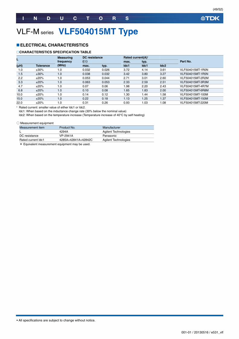
VLF-M series VLF504015MT TypeELECTRICAL CHARACTERISTICS
CHARACTERISTICS SPECIFICATION TABLE
Rated current: smaller value of either Idc1 or Idc2.Idc1: When based on the inductance change rate (30% below the nominal value)Idc2: When based on the temperature increase (Temperature increase of 40°C by self heating)
○Measurement equipment
* Equivalent measurement equipment may be used.
L Measuring frequency(MHz)
DC resistance ( )
Rated current(A)
Part No.max. typ.(µH) Tolerance max. typ. Idc1 Idc1 Idc2
1.0 ±30% 1.0 0.032 0.026 3.72 4.14 3.61 VLF504015MT-1R0N1.5 ±30% 1.0 0.038 0.032 3.42 3.80 3.27 VLF504015MT-1R5N2.2 ±20% 1.0 0.053 0.044 2.71 3.01 2.60 VLF504015MT-2R2M3.3 ±20% 1.0 0.063 0.053 2.33 2.59 2.51 VLF504015MT-3R3M4.7 ±20% 1.0 0.07 0.06 1.98 2.20 2.43 VLF504015MT-4R7M6.8 ±20% 1.0 0.10 0.08 1.65 1.83 2.00 VLF504015MT-6R8M
10.0 ±20% 1.0 0.14 0.12 1.30 1.44 1.58 VLF504015MT-100M15.0 ±20% 1.0 0.22 0.18 1.13 1.25 1.37 VLF504015MT-150M22.0 ±20% 1.0 0.31 0.26 0.93 1.03 1.08 VLF504015MT-220M
Measurement item Product No. ManufacturerL 4294A Agilent TechnologiesDC resistance VP-2941A PanasonicRated current Idc1 4285A+42841A+42842C Agilent Technologies
(50/52)
I N D U C T O R S
001-01 / 20130516 / e531_vlf.fm
• All specifications are subject to change without notice.
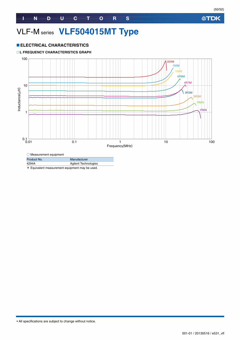
VLF-M series VLF504015MT TypeELECTRICAL CHARACTERISTICS
L FREQUENCY CHARACTERISTICS GRAPH
○Measurement equipment
* Equivalent measurement equipment may be used.
0.1
1
10
100
0.01 0.1 1 10 100
Indu
ctan
ce( µ
H)
Frequency(MHz)
3R3M2R2M
1R5N
1R0N
100M
6R8M
4R7M
220M 150M
Product No. Manufacturer4294A Agilent Technologies
(51/52)
I N D U C T O R S
001-01 / 20130516 / e531_vlf.fm
• All specifications are subject to change without notice.
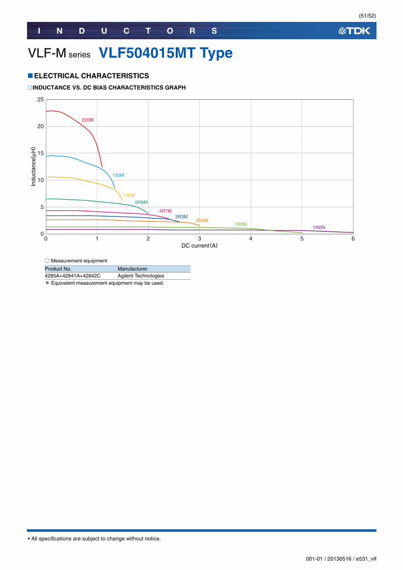
VLF-M series VLF504015MT TypeELECTRICAL CHARACTERISTICS
INDUCTANCE VS. DC BIAS CHARACTERISTICS GRAPH
○Measurement equipment
* Equivalent measurement equipment may be used.
0 1 2 3 4 5 6DC current(A)
0
25
20
15
10
5
Indu
ctan
ce( μ
H)
3R3M2R2M
1R5N1R0N
100M
6R8M
4R7M
220M
150M
Product No. Manufacturer4285A+42841A+42842C Agilent Technologies
(52/52)
I N D U C T O R S
001-01 / 20130516 / e531_vlf.fm
• All specifications are subject to change without notice.
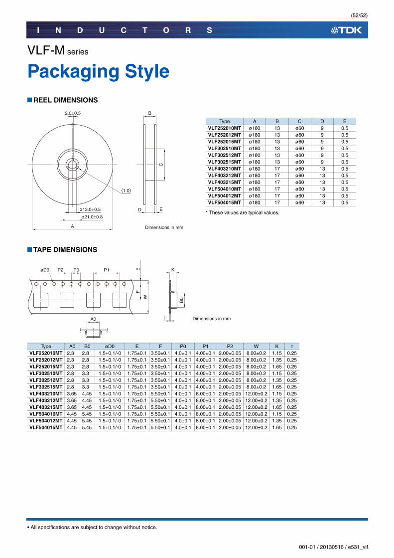
VLF-M series
Packaging StyleREEL DIMENSIONS
* These values are typical values.
TAPE DIMENSIONS
Type A B C D EVLF252010MT ø180 13 ø60 9 0.5VLF252012MT ø180 13 ø60 9 0.5VLF252015MT ø180 13 ø60 9 0.5VLF302510MT ø180 13 ø60 9 0.5VLF302512MT ø180 13 ø60 9 0.5VLF302515MT ø180 13 ø60 9 0.5VLF403210MT ø180 17 ø60 13 0.5VLF403212MT ø180 17 ø60 13 0.5VLF403215MT ø180 17 ø60 13 0.5VLF504010MT ø180 17 ø60 13 0.5VLF504012MT ø180 17 ø60 13 0.5VLF504015MT ø180 17 ø60 13 0.5
Eø13.0±0.5
ø21.0±0.8
C
B2.0±0.5
A Dimensions in mm
(1.0)
D
FE
W
P0P2øD0 P1
A0 t
B0
K
Dimensions in mm
Type A0 B0 øD0 E F P0 P1 P2 W K tVLF252010MT 2.3 2.8 1.5+0.1/-0 1.75±0.1 3.50±0.1 4.0±0.1 4.00±0.1 2.00±0.05 8.00±0.2 1.15 0.25VLF252012MT 2.3 2.8 1.5+0.1/-0 1.75±0.1 3.50±0.1 4.0±0.1 4.00±0.1 2.00±0.05 8.00±0.2 1.35 0.25VLF252015MT 2.3 2.8 1.5+0.1/-0 1.75±0.1 3.50±0.1 4.0±0.1 4.00±0.1 2.00±0.05 8.00±0.2 1.65 0.25VLF302510MT 2.8 3.3 1.5+0.1/-0 1.75±0.1 3.50±0.1 4.0±0.1 4.00±0.1 2.00±0.05 8.00±0.2 1.15 0.25VLF302512MT 2.8 3.3 1.5+0.1/-0 1.75±0.1 3.50±0.1 4.0±0.1 4.00±0.1 2.00±0.05 8.00±0.2 1.35 0.25VLF302515MT 2.8 3.3 1.5+0.1/-0 1.75±0.1 3.50±0.1 4.0±0.1 4.00±0.1 2.00±0.05 8.00±0.2 1.65 0.25VLF403210MT 3.65 4.45 1.5+0.1/-0 1.75±0.1 5.50±0.1 4.0±0.1 8.00±0.1 2.00±0.05 12.00±0.2 1.15 0.25VLF403212MT 3.65 4.45 1.5+0.1/-0 1.75±0.1 5.50±0.1 4.0±0.1 8.00±0.1 2.00±0.05 12.00±0.2 1.35 0.25VLF403215MT 3.65 4.45 1.5+0.1/-0 1.75±0.1 5.50±0.1 4.0±0.1 8.00±0.1 2.00±0.05 12.00±0.2 1.65 0.25VLF504010MT 4.45 5.45 1.5+0.1/-0 1.75±0.1 5.50±0.1 4.0±0.1 8.00±0.1 2.00±0.05 12.00±0.2 1.15 0.25VLF504012MT 4.45 5.45 1.5+0.1/-0 1.75±0.1 5.50±0.1 4.0±0.1 8.00±0.1 2.00±0.05 12.00±0.2 1.35 0.25VLF504015MT 4.45 5.45 1.5+0.1/-0 1.75±0.1 5.50±0.1 4.0±0.1 8.00±0.1 2.00±0.05 12.00±0.2 1.65 0.25