Embed Size (px)
Citation preview

54 InsideGNSS J U L Y / A U G U S T 2 0 1 3 www.insidegnss.com
Since March 2011 the European Geostationary Overlay System (EGNOS) has provided integ-rity information throughout
Europe. This allows aircraft to perform approaches to an increasing number of European runways without the need of expensive ground-based navigation equipment.
With the Global Positioning System being upgraded, the Russian GLONASS constellation having reached full opera-tional status again, and all four Galileo in-orbit-validation (IOV) satellites being in orbit, the number of dual-frequency
pseudorange sources is quickly increas-ing. China is also deploying its own GNSS, BeiDou. The resulting large num-ber of usable GNSS signals not only has an effect on the availability of the GNSS services (e.g., in urban environments) but may also allow new integrity con-cepts based on multiple constellations.
Navigation in Commercial Aviation TodayFor many decades the primary means of navigation has been based either on ground-based systems (radio naviga-tion) or inertial systems (gyroscopes). The accuracy and durability of these systems has improved over the years so that precision approach operations are common nowadays.
In commercial aviation, naviga-tion is usually performed using radio navigation aids. For final approach and landing, either visual cues or RF-based guidance systems can be used. All these systems, however, require maintenance and frequent calibration in order to ensure continuous availability. More-over, the existing systems’ versatility is limited.
With GNSS-based air navigation, many of these disadvantages can be overcome. Aircraft now could perform curved approaches to improve air-space capacity or to implement steep approaches for optimal noise abatement (see T. Lüken et alia in the Additional Resources section). Further, because fewer navigation beacons are needed,
WORKING PAPERS
With the EGNOS safety-of-life service being declared available, the first four Galileo satellites in orbit, and other constellations being upgraded to dual-frequency capability, now is a good time to investigate the effects of an increased number of ranging sources on integrity. This article compares two future integrity concepts that are believed to benefit the most from these additional ranging sources: an upgraded dual-frequency satellite-based augmentation system and an advanced receiver autonomous integrity monitoring algorithm with optimized continuity and integrity allocation.
Integrity for Aviation: Comparing Future Concepts
JAN SPEIDEL, MICHEL TOSSAINT, STEFAN WALLNER, JOSÉ ÁNGEL ÁVILA-RODRÍGUEZEUROPEAN SPACE AGENCY
© iS
tock
phot
o.co
m/m
illio
nhop
e
www.insidegnss.com J U L Y / A U G U S T 2 0 1 3 InsideGNSS 55
the costs of ground-based systems can be reduced significantly, making them attractive for smaller airports as well.
In order to use GNSS as the pri-mary source for navigation in aviation, stringent requirements have to be met. GNSS use in safety-critical applications makes integrity mandatory: the timely provision of information to users about the level of trustworthiness of a posi-tion solution by defining the maximum deviation from the true position with a certain amount of probability.
GNSS Integrity SystemsSeveral methods exist to provide integ-rity. One well-established method of distributing integrity information uses of space-based augmentation systems (SBASs). These employ a combination of monitoring stations distributed across the area of interest and a master control station that processes the positioning inaccuracies for generating the integrity message. Finally, a set of uplink stations transmits the correction information via geostationary satellites for re-transmis-sion to users.
Because the true positions of the monitoring stations are known and can be compared with the computed posi-tion solutions at these locations based on GNSS signals in space, the integrity and accuracy of the signal can be determined and forwarded to users.
Another approach is the ground-based augmentation system (GBAS). Here, ground monitoring stations located close to airports are used, which transmit correction signals directly to the aircraft via RF links. Integrity infor-mation can be obtained by comparing the true position of the ground station with the calculated position solution from the GNSS constellation.
Both SBAS and GBAS are very powerful methods to provide the user with integrity information. However, their infrastructure is very complex and therefore costly. The requirement for informing the user about a loss of integrity within seconds demands a high amount of computing power and facilities.
A third way of providing integrity information is to perform calculations within the user equipment itself, which is called receiver autonomous integrity monitoring (RAIM). Most of the time sufficient satellites are visible to support multiple redundant position calculations — the crucial element of RAIM tech-niques — from which a level of integrity can be derived.
Based on GPS, several SBASs have been implemented. The U.S. Wide Area Augmentation System (WAAS) covers the continental (or contiguous) United States (CONUS) and most parts of Alaska, Canada, and Mexico. The
European GNSS Navigation Overlay System (EGNOS) provides integrity and improved accuracy for the European continent. Also, Japan and India have implemented their own SBASs, called Multi-functional Satellite Augmenta-tion System (MSAS) and GPS Aided Geo Augmented Navigation (GAGAN), respectively. Russia is implementing a WAAS-compatible SBAS covering their territory (System for Differential Correc-tions and Monitoring, or SDCM).
Aviation RequirementsAlthough all three existing method-ologies (SBAS, GBAS, and RAIM) provide integrity information, they do not achieve the same level of integrity. Depending on an aircraft’s approach mode, it must operate with a more or less stringent alert limit.
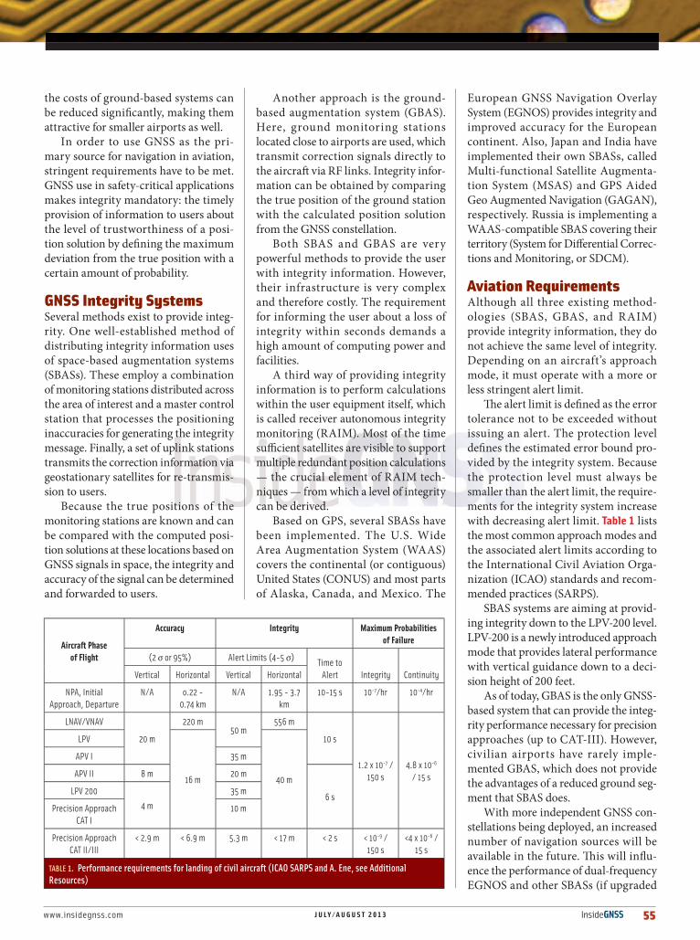
The alert limit is defined as the error tolerance not to be exceeded without issuing an alert. The protection level defines the estimated error bound pro-vided by the integrity system. Because the protection level must always be smaller than the alert limit, the require-ments for the integrity system increase with decreasing alert limit. Table 1 lists the most common approach modes and the associated alert limits according to the International Civil Aviation Orga-nization (ICAO) standards and recom-mended practices (SARPS).
SBAS systems are aiming at provid-ing integrity down to the LPV-200 level. LPV-200 is a newly introduced approach mode that provides lateral performance with vertical guidance down to a deci-sion height of 200 feet.
As of today, GBAS is the only GNSS-based system that can provide the integ-rity performance necessary for precision approaches (up to CAT-III). However, civilian airports have rarely imple-mented GBAS, which does not provide the advantages of a reduced ground seg-ment that SBAS does.
With more independent GNSS con-stellations being deployed, an increased number of navigation sources will be available in the future. This will influ-ence the performance of dual-frequency EGNOS and other SBASs (if upgraded
Aircraft Phase of Flight
Accuracy Integrity Maximum Probabilities of Failure
(2 σ or 95%) Alert Limits (4-5 σ) Time to Alert Integrity ContinuityVertical Horizontal Vertical Horizontal
NPA, Initial Approach, Departure
N/A o.22 - 0.74 km
N/A 1.95 - 3.7 km
10-15 s 10-7/hr 10-4/hr
LNAV/VNAV
20 m
220 m50 m
556 m
10 s
1.2 x 10⁻⁷ / 150 s
4.8 x 10⁻⁶ / 15 s
LPV
16 m 40 m
APV I 35 m
APV II 8 m 20 m
6 sLPV 200
4 m
35 m
Precision Approach CAT I
10 m
Precision Approach CAT II/III
< 2.9 m < 6.9 m 5.3 m < 17 m < 2 s < 10-9 / 150 s
<4 x 10⁻⁶ / 15 s
TABLE 1. Performance requirements for landing of civil aircraft (ICAO SARPS and A. Ene, see Additional Resources)

56 InsideGNSS J U L Y / A U G U S T 2 0 1 3 www.insidegnss.com
to dual-frequency operation like EGNOS) as well as improved RAIM algorithms, which this article further investigates.
SBAS and Possible Future ImprovementsAs of today all SBAS systems only augment the civil L1 signal of GPS. The protection level is specified by the RTCA standard RTCA/DO-208, “Minimum Operational Performance Stan-dards for Airborne Supplemental Navigation Equipment Using Global Positioning System” as:
where G is the geometry matrix and W is the weighting matrix with the diagonal elements being the inverted pseudorange variances with:
By only transmitting the total variance, σi, a user is able to determine the vertical protection level (VPL) — but at a high cost: a σi must be selected that is large enough to sufficiently bound even rather theoretical conditions where large errors occur simultaneously to several satellite/receiver pseudoranges at the same time.
Receivers must account for ionospheric delays to signals propagating through the atmosphere, the largest error con-tributor in the user equivalent range error (UERE) budget for a single-frequency user, by incorporating into their position solutions the GIVE (grid ionospheric vertical error) informa-tion determined by the SBAS ground network. Local effects of the ionosphere need to be covered by a sufficient overboundingmethodology, which is unavoidable from a safety perspective. However this may potentially lead to a very conservative VPL.
With the GPS Block IIF satellite upgrade to a dual-frequen-cy civil signal (L1+L5) in progress, the pseudorange error will be significantly reduced as the dual-frequency linear combina-tion of the range measurements cancels out the first-order iono-spheric error directly at the user level. Additionally, as proposed in the article by T. Walter et alia (2010), improvements can be made to the VPL determination by considering a more realistic treatment of the variances and by adding bias terms to better map faults with non-Gaussian behavior.
This proposal distinguishes between two hypotheses: Fault-free (H0) and faulted (H1). In the fault-free condition, the VPL is determined as follows:
For faulted conditions, the VPL is calculated like this:
with s0(3,i) projecting the ranging error onto the vertical posi-tion estimate and being the expected error variance under nominal (fault-free) conditions. For the H0 case, a bias term is
added to account for nominal non-Gaussian errors. In H1 the maximum bias under faulty conditions is also added.
Finally, the user VPL is
Additionally, the transition from Message Type 27 to Mes-sage Type 28 (MT28) on WAAS/SBAS satellites will in general reduce the user differential range error (UDRE) — the confi-dence bound on GPS/GEO clock and ephemeris corrections — and thus improve availability and integrity, discussed further in T. Walter et alia (2001).
Figure 1 shows the improved availability of integrity of an upgraded EGNOS based on dual-frequency GPS and with MT28 implemented.
Evolution of RAIM AlgorithmsRAIM algorithms have been investigated since the late 1980s starting with publications by Y. C. Lee (1986), R. G. Brown et alia, and M. Brenner (1990).
This section presents three different RAIM algorithms and explains their capabilities with respect to improved integrity. The first one is the Least-Squares-Residuals (LS) RAIM algo-rithm that is typically implemented in today’s aviation grade GPS receivers and provides low-precision lateral integrity only. The second RAIM approach is based on the Separation Solu-tion (SS) method.
Lastly, we present the Multiple Hypothesis Solution Separa-tion (MHSS) method, which is an improvement on SS RAIM. MHSS seems to be a promising algorithm to allow vertical guidance up to LPV-200 capability based on just two inde-pendent constellations. An optimization of the MHSS RAIM method is also presented which further improves the overall integrity performance especially in multiple satellite failure conditions.
LS RAIM. This algorithm compares the size of the least squares residuals of redundant pseudorange measurements. If one of the measurements is faulty, the residuals will become large. By defining a threshold for the residuals and a test sta-tistic, a receiver can determine whether a position solution is valid or faulty.
In 1995, T. Walter and P. Enge (see Additional Resources) improved the LS method by including individual weighting of the pseudorange measurements, depending on the eleva-tion angle. In order to identify a measurement fault, an error slope is computed for each satellite and then compared to the maximum allowed error slope (or error threshold). The vertical protection level can then be calculated by
where T is the detection threshold, which depends on the num-ber of satellites N and the desired probability of false alarms PFA. The factor k(PMD) is the distance (in number of standard deviations) from the specified integrity risk (PMD). The vertical positioning confidence is given by σv.
RAIM in Aviation (TSO-RAIM). In aviation, RAIM is used to
WORKING PAPERS

www.insidegnss.com J U L Y / A U G U S T 2 0 1 3 InsideGNSS 57
improve the integrity of GPS receivers during en route, terminal, and non-precision approach phases of the flight. However, as of today no RAIM imple-mentation exists for any application requiring integrity in the vertical plane (i.e., precision approaches), which has more stringent certification require-ments.
Errors in vertical navigation are considered to pose a higher safety risk and are therefore designated “Hazard-ous” in the International Civil Aviation Organization (ICAO) Safety Manage-ment Manual (Doc. 9859), compared to “Major” for horizontal errors. This leads to a much more stringent assessment of possible errors that must be considered if RAIM is extended to support vertical navigation.
In literature on the subject, RAIM algorithms that also provide protec-tion against vertical errors are often called “Advanced RAIM” (ARAIM) algorithms. Moreover, note that input parameters for the ARAIM algorithm will most likely need to be provided by an ARAIM ground-monitoring network compliant with the necessary safety requirements.
For the certification of airborne GPS receivers limited to lateral navigation, the Federal Aviation Administration (FAA) published a Technical Standard
Order (TSO-C129a), which is based on DO-208. It does not precisely specify which RAIM algorithm is to be used. Instead, a test scenario is defined and the required availability output is given: “The RAIM function shall provide worldwide availability of at least 95% […]”.
The LS RAIM algorithm meets the TSO requirements and is therefore sometimes called TSO-RAIM. We adopted LS RAIM as the baseline RAIM algorithm for the simulations performed in the context of this article.
Solution Separation RAIM. A very dif-ferent RAIM method was proposed by Brown et alia, called Solution Separa-tion (SS). Since the number of received signals usually come from more than the minimum four satellites, the posi-tion can be determined based on a sub-set of the available satellites only. If one faulty satellite is present, then one of the subsets will contain only healthy satel-lites. The early SS RAIM approaches for detecting faulty satellites were based on a comparison of the position estimates of all subsets in the position domain, as described in the article by M. Brenner (1995).
Compared to LS RAIM, the Solution Separation method is able to detect mul-tiple satellite failures (however at high computational cost). For this purpose,
the probability of a satellite failure (Psat)is computed to determine the probabil-ity of multiple simultaneous satellite failures. The VPL is determined for all subsets:
with xv being the vertical component of the navigation error (i.e., the difference between the estimated position with the partial and all-in-view satellite sets) and k(PMD ) representing the distance (in number of standard deviations) from the specified integrity risk value. Again, σv is the vertical positioning confidence.
As with LS RAIM, SS RAIM also adds a confidence interval σv to the ver-tical error in order to protect the user against the very hypothetical combined error along all LOS. For SS RAIM this means that the maximum position solu-tion separation between a subset and the all-in-view case is considered as the condition against which the algorithm must protect, even though the probabil-ity of failure that leads to that subset is extremely low. (See the article by A. Ene for further discussion of this point.)
Multiple Hypothesis Solution Separa-tion RAIM. To avoid this overly conserva-tive requirement in SS RAIM, another approach analyzes every threat with respect to its probability of occurrence. The Multiple Hypothesis Solution Sep-aration RAIM algorithm (MHSS) “… weighs fault modes based on their (prior) probability and eliminates the compari-son against a given error threshold.” This method was first presented in the 1987 article by B. Parkinson et alia cited in Additional Resources.
A common approach is to equally allocate the allowable integrity risk P(HMI) among all possible fault modes (equal allocation). This results in the “… maximum conditional probability of detection regardless of which satellite fails,” as stated in the article by Y. C. Lee (2007).
In order to meet the more stringent requirements necessary for LPV-200, the MHSS RAIM algorithm must take into account biases in range measurements and utilize user range error (URE) or user range accuracy (URA) for the eval-
FIGURE 1 Improved availability and integrity based on L1-L5 GPS signal and with MT28 being imple-mented
L1-L5 Dual Frequency / 28 GPS / GEOs set to mon / MT28 Implemented / RIMS Elevation Mask 5 degTimestep 300s / Duration 10 days / Gridsize 2.5 x 2.5 deg
90
60
30
0
-30
-60
-90
Latit
ude (
deg)
-180 -120 -60 0 60 120 180Longitude (deg)
>50
<50
<40
<35
<30
<25
<20
<13
<12
Verti
cal p
rote
ctio
n le
vel 9
9.9%
m

58 InsideGNSS J U L Y / A U G U S T 2 0 1 3 www.insidegnss.com
uation of accuracy and integrity. The VPL equation for the nth
subset is then
where
represents the detection threshold for the nth test statistic. This threshold depends on the false alert probability factor
Kffd,n and the standard deviation of the difference between the full set and the nth subset in the vertical plane σdV, n. A bias term is also added, which ensures that the false alert probability is still met even with biases present in the range measurements.
Furthermore, an integrity buffer is added:
with Kmd,n being the missed detection probability factor. Finally, the total VPL is determined by
The factors Kffd,n and Kmd,n must be selected so that the con-tinuity and integrity requirements are met. An easy way to achieve this is to equally divide the total false alert probability requirement among all satellites in view (N):
Here, Pfa is the probability of false alarm. In the same way the total allowable integrity risk is divided among all satellites, taking into account the a priori probability Pap,n of each satellite:
where Q-1 stands for the inverse of the complement of the one-sided standard normal cumulative distribution function, CDF.
However, this results in varying Dn, which directly influenc-es the VPL. In order to optimize the allocation of the integrity and continuity budget, a method must be found that results in identical VPLn for all n = 1,2 ..., N (outlined in Phase II of the FAA’s GNSS Evolutionary Architecture Study).
MHSS RAIM Optimization. The article by Blanch et alia (2010) describes such a mathematical approach to optimize the integ-rity and continuity allocation at the same time. The algorithm works as follows.
Find x and μ such that:
and
where
and
Here,
One way to find x and μ is to select one of the two constrain-ing equations (14) or (15) and determine x(μ). Then, by moving along that function we find the point where both (14) and (15) are fulfilled. This process must be performed numerically and requires a large amount of processing time. However, by select-ing upper and lower bounds beforehand and by using interval halving, the computational burden can be lowered significantly.
Simulation Assumptions All simulations presented here aim to represent the situation as it is assumed to be circa 2025. This includes the presence of up to four fully operational GNSS constellations (GPS, Gali-leo, GLONASS, and BeiDou), which provide dual-frequency navigation signals.
We modeled the constellations based on either real orbit parameters (GPS) or the expected constellation geometry (Gal-ileo, GLONASS, and BeiDou). We assumed that the ground segment of EGNOS has been upgraded by additional reference stations in North Africa to a total of 41 stations (see also Figure 2). We also assumed that Message Type 28 is being transmitted.
EGNOS Simulation Assumptions. The assumptions for the dual-frequency, dual-constellation EGNOS scenarios are derived from the single frequency VPL assumptions from the RTCA document, “Minimum Operational Performance Standards for Global Positioning System/Wide Area Augmentation System Airborne Equipment (GPS/WAAS MOPS),” using improved equations — Equation (3) to (5) introduced earlier — to calcu-late the VPL. Additionally, we selected the parameters shown in Table 2.
The total fault-free error is modeled as follows:
The iono-free combination for dual-frequency mode is
and σair,j are σtropo,i determined as described in the GPS/WAAS MOPS for the Airborne Accuracy Designator B type of receiv-ers.
WORKING PAPERS

www.insidegnss.com J U L Y / A U G U S T 2 0 1 3 InsideGNSS 59
ARAIM Simulation Assumptions. Here, the MHSS algorithm with optimal integ-rity and continuity allocation was used as described in the article by J. Blanch et alia (2010). Table 3 shows the assump-tions for the ARAIM simulations.
These values are based on the ICAO SARPS requirements and were confirmed to be suitable for LPV-200 ARAIM simulations in J. Blanch et alia(2011).
In terms of accuracy and biases, Table 4 shows our assumptions.
A few notes regarding Table 4 are required. Compared to other publica-tions on this topic, the accuracy assump-tions for GPS made here could be con-sidered optimistic. However, because this article investigates the performance of a multi-constellation system that would be in place 12 years from now, we incorporated the expected improve-ment of GPS by adding GPS Block III satellites to the constellation that will be made possible by the Block IIIs’ rather low URE and URA.
The minimum allowed elevation angles (masking) were selected to be 5 degrees for the GPS constellation and 10 degrees for all others.
A l l scenar ios include two geo-stationary naviga-tion sources repre-senting a possible future upgrade of the EGNOS space segment to support Galileo-like range measurements from GEO. The accuracy assumptions for GEO were taken from EGNOS testing.
The elevation-dependent ranging budgets (including receiver noise, mul-tipath effect, ionospheric delay, and tropospheric delay) are determined in two different ways. For the GPS con-stellation, we used the formulas from the GPS/WAAS MOPS for the Airborne Accuracy Designator A type, adapting them for dual-frequency operation:
For the Galileo, GLONASS, and Bei-Dou constellations, the UERE is based on a lookup table given in Table 5 with linear interpolation between the steps.
Scenario Setup The simulations presented here were performed using ESA’s service volume simulator GAIA, which was developed within the GNSS Evolution Team and recently upgraded to support the MHSS RAIM. In order to facilitate comparison of the simulations with the results pre-sented in other publications, the results are presented with charts using the same layout as the popular Matlab Algorithm Availability Simulation Tool (MAAST) from Stanford University.
The main goal of the simulations performed for this article is to compare the performance of modern ARAIM algorithms with an upgraded EGNOS and various numbers of available GNSS constellations, assuming that EGNOS
will eventually be providing corrections and integrity data for all four GNSS con-stellations, not just GPS. For that rea-son, we conducted several simulation runs using the same algorithm (either EGNOS or ARAIM) but adding more and more constellations to the scenario.
The duration of both the EGNOS and ARAIM scenarios were set to 10 sidereal days, which is the orbital repeat period of Galileo. We selected a time step of 300 seconds with a user location spacing of 2.5 by 2.5 degrees.
The scenario set starts with a con-stellation of 18 GPS satellites and two GEO navigation sources, represent-ing the (hypothetical) situation of an underperforming GPS constellation or the situation when fully operational capability (FOC) for GPS L5 has not yet been achieved. The GPS satellites’ and GEO navigation sources’ orbital parameters are based on a two-line ele-ment (TLE) file published on February 18, 2011, with the locations of the two geostationary navigation sources using the orbital parameters of the satellites Artemis and AOR-E.
For the simulation runs presented in this article, more and more GPS sat-ellites are added to the scenario until a total number of 30 is reached, repre-senting the situation as it is today. Next, Galileo satellites are successively added including the initial operational capabil-ity (IOC) constellation size (18 satellites) and finally the FOC geometry (27 active satellites).
In the following run, 24 GLONASS satellites are added to the scenario. Here, we assumed that the performance of
EGNOS
KHMI 5.33
Kfault 2.33
Biasnom 0.5m
Biasfault 5.33 • σflt
TABLE 2. EGNOS VPL Equation Assumptions
MHSS ARAIM
P(HMI) 2 • 10-7/approach
Pfa 4 • 10-6/approach
Pap 1 • 10-5/approach
TABLE 3. MHSS RAIM simulation integrity and continuity risk allocations
GPS Galileo, GLONASS,
BeiDou
GEO
URE/SISE 0.22m 0.67m 0.50m
URA/SISA 0.33m 0.957m 0.75m
Nominal_Bias 0.10m 0.0m 0.0m
Maxmimum_Bias 0.75m 1.0m 1.0m
TABLE 4. MHSS ARAIM simulation accuracy and bias assumptions for user range error (URE)/signal-in-space error (SISE), user range accuracy (URA)/signal-in-space accuracy (SISA), and biases
Galileo/GLONASS/BeiDou
σn,user
(vs elevation)
5° 0.4529 50° 0.2359
10° 0.3553 55° 0.2339
15° 0.3063 60° 0.2302
20° 0.2638 65° 0.2295
25° 0.2593 70° 0.2278
30° 0.2555 75° 0.2297
35° 0.2504 80° 0.2310
40° 0.2438 85° 0.2274
45° 0.2396 90° 0.2277
TABLE 5. User equivalent range error (UERE) calculation table

60 InsideGNSS J U L Y / A U G U S T 2 0 1 3 www.insidegnss.com
an upgraded GLONASS constellation would be similar to the Galileo constel-lation in terms of URA and probability of failure.
Finally, 24 satellites are added rep-resenting a future BeiDou constella-tion, resulting in a total of 105 satellites. Again, a performance similar to the Galileo satellites is assumed for BeiDou. As of today the BeiDou constellation is expected to consist of 35 active satellites.
We used a pure Keplerian propagator to predict orbital parameters. The Earth was modeled using the WGS84 ellipsoid.
Simulation ResultsThe following section describes the results of this progressive series of simu-lated scenarios.
Multi-Constellation EGNOS. Figure 2shows the 99.9 percentile of VPL using two dual-frequency constellations (GPS and Galileo) consisting of 28 (nominal GPS constellation assumption in 2010) and 27 Galileo satellites, respectively. As a result, the VPL throughout the Central European region is below 10 meters.
In order to analyze the performance of EGNOS with respect to an increas-ing number of monitored satellites, two user locations were selected and inves-tigated in more detail: one in the Cen-tral European region (Lat/Lon 50°/0°) and one in the Southern African region (Lat/Lon 30°/0°). The best performance of EGNOS is expected in the Central European region, where the density of the ranging and integrity monitoring stations (RIMS) is the highest. The sec-ond location is relatively far away from the specified EGNOS coverage area; therefore, higher protection levels are generally expected here.
If we look at Figure 3, we see that the EGNOS performance improves as the number of monitored satellites increas-es. For the Central European region, however, the improvement is not par-ticularly significant when compared to the Southern African region. If EGNOS could be based on three fully deployed dual-frequency constellations, VPLs needed to achieve LPV-200 would even be achieved in the Southern African region.
One should keep in mind, though, that further requirements exist for LPV-200 in addition to the VPL (e.g., the 4-meter 95 percent accuracy require-ment, the 10-meter fault-free 10-7 verti-cal position error requirement, or the 15-meter effective monitor thresholdrequirement), as discussed in the paper by J. Blanch et alia (2011). The results presented here can therefore only indi-cate a tendency of the capabilities of an
upgraded multi-constellation EGNOS.AR AIM. In the same way as for
EGNOS in Figure 2, Figure 4 displays the VPL based on two constellations (GPS and Galileo) using ARAIM, in this case, the MHSS algorithm. These two figures allow for easy comparison of the charac-teristics of EGNOS and ARAIM-based integrity.
In terms of performance improve-ment with increasing number of con-
WORKING PAPERS
FIGURE 3 Comparison of dual-frequency EGNOS and MHSS ARAIM performance (optimal integrity and continuity allocation) with increasing number of satellites for two user locations
σMEO - 0.33m σGEO = 0.75m BiasNom = 0.50m60
50
40
30
20
10
0
Verti
cal P
rote
ctio
n Le
vel (
99.9
%) (
m)
10 20 30 40 50 60 70 80 90 100 110Number of satellites [-]
FIGURE 2 VPL of EGNOS dual-frequency setup (GPS + Galileo) with extended RIMS network
L1-L5 Dual Frequency / 28 GPS + 27 GAL / GEOs set to mon / MT28 Implemented / RIMS Elevation Mask 5 deg / Timestep 300s / Duration 10 days / Gridsize 2.5 x 2.5 deg
90
60
30
0
-30
-60
-90
Latit
ude (
deg)
-180 -120 -60 0 60 120 180Longitude (deg)
>50
<50
<40
<35
<30
<25
<20
<13
<12
Verti
cal p
rote
ctio
n le
vel 9
9.9%
m

www.insidegnss.com J U L Y / A U G U S T 2 0 1 3 InsideGNSS 61
stellations, we can say that one fully operational constellation (consisting of 28 satellites) is already sufficient to reach acceptable protection levels (see Figure 3).
We must remember, however, that ARAIM based on a single constellation increases the effect of a common-mode failure, which immediately results in a loss of integrity. With more constella-tions available, integrity could still be provided in such situations.
The simulations show that the MHSS ARAIM concept can achieve VPL levels similar to EGNOS. With a fully deployed Galileo constellation, Vertical Protection Levels well below 35 meters are possible, supporting LPV-200. Adding a third constellation allows even VPL ranges for CAT-I precision approach conditions to be reached.
Figure 3 also shows that for ARAIM integrity, the user location does not really inf luence the achievable pro-tection level. On the other hand, the performance of ARAIM is extremely dependent on the number of satellites available.
Open Points and OutlookThe results presented in this article show the possibilities of both ARAIM and an
upgraded EGNOS in the context of an increasing number of GNSS constella-tions. However, many important issues still need to be investigated further when comparing ARAIM and EGNOS. We will discuss some of these here.
Failure Modes for ARAIM. A EU/US ARAIM Working Group identified sev-eral potential errors that pose a threat to the ARAIM integrity system, which are elaborated in the previously reference paper by J. Blanch et alia (2011). The threats have been classified as “nomi-nal,” ”narrow failure,” and “wide failure” errors.
Nominal errors can occur when all parts of the system are in their nominal operational state. This includes errors that cannot be avoided during opera-tions in this state (e.g., nominal clock and ephemeris errors, nominal signal deformation errors, antenna biases, tropospheric errors, or code noise and multipath errors). Ionospheric effects are not considered as part of nominal errors, because dual-frequency systems that allow the cancellation of the first-order ionospheric effects are assumed to be in use.
Narrow failure errors are errors of the ground segment or the space seg-ment that only affect one satellite. The
source can be clock and ephemeris esti-mation errors, signal deformations, or code-carrier incoherence.
Wide failure errors result in a deg-radation of the navigation signal and the navigation message of more than one satellite. These errors can originate from inadequate manned operations or failures in the message generation pro-cess. This type of error can also arise from a failure in the spacecraft control segment. Finally, erroneous Earth orien-tation parameters (EOP) could induce a constellation-wide error, rendering an entire constellation invalid. Therefore, constellations need to be monitored by independent observations to quickly detect possible EOP errors.
Several ways to mitigate expected threats have been considered. As sug-gested by J. Blanch et alia, either the ground segment or the ARAIM algo-rithm must cover such contingencies, depending on the type of threat and its associated threat dynamics either the ground segment or the ARAIM algo-rithm must cover it.
Guarantors for the ARAIM. Various methods to guarantee the reliable per-formance of ARAIM have been sug-gested. User algorithm input parameters(including URA/SISA, URE/SISE, and the probability of satellite or constel-lation-wide failures) drive the perfor-mance of the ARAIM concept. The essential question now is how to deter-mine these parameters sufficiently from a safety perspective for every GNSS con-stellation contributing to the ARAIM solution — without being too conserva-tive (thus penalizing service availability), without being too optimistic (thus jeop-ardizing safety), and with a minimum level of investment at the infrastructure level.
Reliance on past GNSS observations and their extrapolation into the future may not be enough to determine these parameters. As we all know, a GNSS is not at all a steady-state system, as evo-lutions take place within all elements. Macrocosmically, this includes the evo-lutions of satellite capabilities material-izing, for example, in the different blocks of GPS satellites or major upgrades at the
FIGURE 4 VPL based on dual constellation and two geostationary ranging sources using MHSS RAIM
MHSS RAIM, 28GPS 2GEO 27 GAL / Timestep 300s / Duration 10 days / Gridsize 2.5 x 2.5 deg90
60
30
0
-30
-60
-90
Latit
ude (
deg)
-180 -120 -60 0 60 120 180Longitude (deg)
>18
<18
<16
<14
<12
<10
<8
<9
<4
Verti
cal p
rote
ctio
n le
vel 9
9.9%
m

62 InsideGNSS J U L Y / A U G U S T 2 0 1 3 www.insidegnss.com
ground segment level with the future transition from OCS to OCX. We might well see similar evolution scenarios for the other GNSS in the future, too.
At a microcosmic scale, changes may occur at the satellite/ground seg-ment level even more frequently and completely invisible to the end-user (for instance, the switch from nominal payload units to redundant ones). For all these reasons past performance may not be easy to extrapolate into the future.
Service performance specificationsissued by the GNSS service provider, such as those established by the Depart-ment of Defense for GPS, are an excellent place in which to establish the necessary confidence in the service quality and are very helpful during the definition phase of an ARAIM system.
How legally binding such specifica-tions may be and the consequences in case they are not met at some point in the future remain open questions that need further attention. Nonetheless, these types of specifications may be use-ful as the basis for setting prerequisites for a GNSS to enable in a subsequent step the ARAIM system components needed to estimate guaranteed perfor-mance figures.
The necessity for dedicated ground installations is becoming more and more obvious. An ARAIM-specific ground segment is needed to provide users with relevant ARAIM algorithm input
parameters sufficient to guarantee the system from a safety perspective. This will be ensured by allocating a proper design assurance level to every threat barrier within the ARAIM ground seg-ment.
The definition of an ARAIM ground segment is the essential missing element and dedicated research activities on this subject are currently ongoing.
Possible Implementation of a Coop-erative ARAIM Integrity Service Message Network. Because short-term anomaly detection is covered on the user side by the ARAIM algorithm, the Integrity Service Message (ISM) only has to cover the long-term variations of the signal. Consequently, low update rates of the ISM are acceptable.
As of today, plans call for the ISM to contain information about SISA, SISE, maximum nominal bias, and the prob-abilities of single-satellite and constella-tion-wide faults. The dissemination of a validated navigation message through the ISM may also be considered in the future.
Proposed ISM network channels include transmission via the GNSS con-stellations themselves, drastically limit-ing the maximum data rate available. Another option could be the use of an upgraded SBAS that, in addition to the augmentation signal, also transmits the ISM. Both options have the advantage of using pre-existing data channels that
would avoid the costly upgrade of hard-ware at the user side. The option to dis-seminate ISM through SBAS data links would have the added value that the dis-semination of this safety-of-life–related message is carried out through a system designed according to relevant safety requirements.
Apart from the technical challenges of the ISM delivery, political burdens may also appear. Today, integrity ser-vices are provided by the countries that each system covers. With an ARAIM system being implemented, it could easily happen that one Air Navigation Service Provider (ANSP) delivers the ISM to a flight that then passes through the jurisdiction of another ANSP. This could lead to questions regarding liabil-ity, which need to be investigated.
Another decision must be made as to whether each constellation shall be monitored by an independent ISM checking network. As with SBAS, ARAIM depends on a network of sensor stations in order to generate and verify the ISM. However, the number of neces-sary stations for ARAIM operations is much smaller than for an SBAS.
If ARAIM should eventually be implemented as a successor to SBAS, the already existing SBAS RIMS net-works could be used for that purpose but reduced in size (e.g., only 15 stations for EGNOS RIMS). This would result in significant cost reductions.
WORKING PAPERS
FIGURE 5 Depth of Coverage for a typical GPS constellation with a reduced RIMS network
90
60
30
0
-30
-60
-90
Latit
ude (
deg)
-180 -120 -60 0 60 120 180Longitude (deg)
>5
4
3
2
1
0
Dept
h of
Cove
rage
(DOC
) [-]

www.insidegnss.com J U L Y / A U G U S T 2 0 1 3 InsideGNSS 63
Figure 5 shows that a reduced set of sensor stations worldwide would be capable of providing a sufficient depth of coverage for a typical GNSS constel-lation. As can be seen, all satellites would be in view of at least five ground stations except in the polar regions of the south-ern hemisphere.
With multiple constellations being deployed several scenarios for the ISM checking network could be feasible: • each constellation is monitored by a
dedicated network of sensor stations• all sensor stations monitor all con-
stellations using the same monitor-ing equipment, or
• all sensor stations are equipped withindependent monitoring systems for each constellation. Which scenario will finally be select-
ed is going to be based not only on tech-nical but also on political considerations.
Combined use of EGNOS and ARAIM and Transition Scenarios. With two inde-pendent integrity concepts available by 2025, it would be interesting to figure out how to make use of both of them so that users always have access to the posi-tion solution estimate with the highest integrity.
The EGNOS V3 evolution upgrade includes plans to add the capability to augment the L5 signal of the GPS constellation as well as Galileo signals. Augmentation of GLONASS signals by EGNOS is also being studied as part of the EGNOS V3 upgrade.
Currently, plans do not call for aug-menting BeiDou through EGNOS. How-ever, the simulations presented in this article showed that an additional con-stellation augmented by EGNOS could increase the availability of integrity in the southern hemisphere significantly.
An additional constellation has an even bigger effect on the integrity per-formance of ARAIM, because it lowers the VPL worldwide. As a consequence, when EGNOS V3 and ARAIM become operational, EGNOS could be used to provide high-quality integrity over Cen-tral Europe while a multi-constellation ARAIM was employed for all other user locations. In this way, basic integrity would be available everywhere while
covering the Central European region with two redundant systems.
If redundancy is not a driving fac-tor, ARAIM could be implemented to replace SBAS in the long term. The United States and Europe have indicated that they have different plans here. In the short term, EGNOS is going to be extended to provide integrity based on two constellations starting around 2018, whereas the U.S. WAAS is currently not planning to make use of any other GNSS besides GPS. Consequently, the United States seems to have a higher demand for ARAIM because it could improve integrity significantly across CONUS.
The transition from EGNOS to ARAIM in the long term (>2030) could be realized in the following steps:• ARAIM and EGNOS V3 are fully
deployed. EGNOS serves as the pri-mary integrity source for Europe while ARAIM provides basic integ-rity everywhere else.
• While gaining more and more con-fidence in the operation of ARAIM, its integrity performance increases to a level where it performs equally well as EGNOS.
• ARAIMbecomes the primary sourceof integrity for the EGNOS coverage area as well. The number of EGNOS RIMS is successively reduced from 41 to 15. EGNOS stays operational both for ISM checking and as a fall-back to ARAIM.The advantage of a transition from
EGNOS to ARAIM is mainly a reduc-tion of operational costs because of the following factors: a) real-time requirements at the ground
segment level are not inherent to a user-equipment–based ARAIM architecture
b) SBAS transponders onboard geo-stationary satellites may eventually become obsolete
c) the number of ground sensor stations could be reduced. However, at the time of a possible
transition, EGNOS would be a trusted and well-performing system that is replaced by a completely new system. Further research is therefore necessary to see how this transition could best be
performed in terms of safety, complex-ity, schedule, and cost.
ConclusionARAIM and multi-frequency, multi-constellation SBAS systems perform similarly with respect to improved availability of integrity when the num-ber of constellations increases. ARAIM could possibly decrease the operational cost of providing integrity. However, further research is still needed to evalu-ate ARAIM in light of the full integrity “tree.”
DisclaimerThe views expressed in this article are solely the opinions of the authors and do not reflect those of the European Space Agency. Any quantitative system char-acterizations made use of in this paper together with the derived performance estimates are only for ARAIM simula-tion purposes and need not necessarily represent the performance obtained by the future GNSS systems.
Additional Resources[1] Blanch, J. (2010), and T. Walter,and P. Enge, “RAIM with Optimal Integrity and Continuity Allo-cations Under Multiple failures,” IEEE Transactions on Aerospace and Electronic Systems, Volume: 46, Number: 3, pp. 1235–1247, July 2010
[2] Blanch, J. (2011), and T. Walter, P. Enge, S. Wallner, F. Amarillo Fernandez, R. Dellago, R. Ioannides, B. Pervan, I., Fernandez Hernandez, B. Belabbas, A. Spletter, A., and M. Rippl, “A Proposal for Multi-Constellation Advanced RAIM for Verti-cal Guidance,” The Proceedings of the ION GNSS 2011, Portland, Oregon USA, September 2011
[3] Brenner, M., “Implementation of a RAIM Mon-itor in a GPS Receiver and an Integrated GPS-IRS,” Proceedings of the Third Technical Meeting of the Satellite Division of The Institute of Navigation, Colorado Springs, CO, pp. 397-406, 1990
[4] Brenner, M., “Integrated GPS/Inertial Fault Detection Availability,” Proceedings of The Insti-tute of Navigation 8th International Technical Meeting, Palm Springs, CA, September 1995
[5] Brown, R. G., and P. Y. C. Hwang, “GPS Fail-ure Detection by Autonomous Means Within the Cockpit,” Proceedings of the Annual Meeting of The Institute of Navigation, Seattle, Washington USA, pp. 5–12, June 24–26, 1986
[6] Brown, R. G., and P. W. McBurney, “Self-Containded GPS Integrity Check Using Maximum

64 InsideGNSS J U L Y / A U G U S T 2 0 1 3 www.insidegnss.com
WORKING PAPERS
Solution Separation as the Test Statistic,” Proceed-ings of the First Technical Meeting of the Satellite Division of The Institute of Navigation, Colorado Springs, Colorado USA, pp. 263–268, 1987
[7] Ene, A., “Utilization of Modernized Global Navigation Satellite Systems for Aircraft-based Navigation Integrity,” Dissertation, Department of Aeronautics and Astronautics, Stanford University, California USA, March 2009
[8] Federal Aviation Administration, Phase II of the GNSS Evolutionary Architecture Study, Feb-ruary 2010, <http://www.faa.gov/about/office_org/headquarters_offices/ato/service_units/techops/navservices/gnss/library/documents/media/GEASPhaseII_Final.pdf>
[9] International Civil Aviation Organization, Aeronautical Telecommunications, in Annex 10 to the Convention on International Civil Aviation International Standards and Recommended Prac-tices (SARPs), Volume I (Radio Navigation Aids), Montreal, Canada, July 16, 2007
[10] International Civil Aviation Organization, Safety Management Manual (Doc. 9859), Second Edition, Montreal, Canada, 2009
[11] Lee, Y. C., “Analysis of Range and Position Comparison Methods as a Means to Provide GPS Integrity in the User Receiver,” Proceedings of the Annual Meeting of The Institute of Naviga-tion, Seattle, Washington USA, June 24–26, pp. 1–4, 1986
[12] Lee, Y.C., “Feasibility Analysis of RAIM to Provide LPV-200 Approaches with Future GPS,” Proceedings of the 20th International Technical Meeting of the Satellite Division of The Institute of Navigation, Fort Worth, Texas USA, September 25–28, pp. 2898–2910, 2007
[13] Lüken, T., and E. Groll, F. Antrack, and B. Korn, “Helicopter IFR Steep and Curved Approaches Using SBAS Guidance,” 34th European Rotorcraft Forum, Liverpool, United Kingdom, September 16–19, 2008
[14] Matlab Algorithm Availability Simulation Tool, <http://waas.stanford.edu/~wwu/maast/maast.html>
[15] Parkinson, B. W., and P. Axelrad, “A Basis for the Development of Operational Algorithms for Simplified GPS Integrity Checking,” Proceedings of the First Technical Meeting of the Satellite Division of The Institute of Navigation, Colorado Springs, Colorado USA, pp. 269–276, 1987
[16] Parkinson, B. W., and P. Axelrad, “Autono-mous GPS Integrity Monitoring Using the Pseu-dorange Residual,” Navigation (Washington), Volume: 35, Number: 2, pp. 255–274, 1988
[17] RTCA, Inc., Minimum Operational Perfor-mance Standards for Airborne Supplemental
Navigation Equipment Using Global Positioning System (GPS), Document No. RTCA/DO-208, prepared by SC-159, Washington D.C., July 1991
[18] RTCA, Minimum Operational Performance Standards for Global Positioning System/Wide Area Augmentation System Airborne Equipment,” RTCA Publication DO-229D, 2006
[19] U. S. Department of Defense, Global Posi-tioning System Standard Positioning Service Per-formance Standard, 4th edition, September 2008
[20] U. S. Department of Transportation, Fed-eral Aviation Administration (FAA), TSO-C129a, “Technical Standard Order, Airborne Supplemen-tal Navigation Equipment Using Global Positioning System (GPS),” Washington DC, 1992
[21] Walter, T., and J. Blanch, and JP. Enge, “Verti-cal Protection Level Equations for Dual Frequency SBAS,” Proceedings of the 23rd International Technical Meeting of the Satellite Division of The Institute of Navigation, Portland, OR, pp. 2031-2041, September 21-24, 2010
[22] Walter, T., and P. Enge, “Weighted RAIM for Precision Approach,” Proceedings of the 8th International Technical Meeting of the Satellite Division of The Institute of Navigation (ION GPS-95), Palm Springs, California USA, pp. 1995–2004, September 12–15, 1995
[23] Walter, T., and A. Hansen, and P. Enge, “Mes-sage Type 28,” Proceedings of the ION NTM 2001, Long Beach, California USA, January 2001
AuthorsJan Speidel was a Young Graduate Trainee in the GNSS Evolution Team and Strategy Division at the European Space Agency/ESTEC, The Netherlands, and now works as a Gali-
leo system engineer at OHB System in Bremen, Germany. Speidel holds a Diploma in computer engineering from the University of Applied Sci-ences of Braunschweig/Wolfenbüttel, Germany, a M.Sc. with a major in space technology from Luleå Technical University, Sweden, and a M.Sc. in space technique and instrumentation from Uni-versité Paul Sabatier III Toulouse, France. His main fields of interest are future GNSS integrity con-cepts, inter-satellite link design, and GNSS appli-cations in aviation.
Michel Tossaint is a radio-navigation system engi-neer at the ESA/ESTEC, The Netherlands in the GNSS Evolution Team of the Navigation Director-
ate. Tossaint holds an M.Sc. degree from the fac-ulty of aerospace engineering of Delft University, The Netherlands. His interests are in systems engineering, estimation, and precise carrier phase navigation.
Stefan Wallner graduated with a Diploma in tech-no-mathematics and was research associate at the Institute of Geodesy and Navigation at the Federal Armed Forces
Germany in Munich. Since 2010 he has worked at the European Space Agency/ESTEC in the field of Galileo evolution, future GNSS integrity schemes, and RNSS compatibility.
José Ángel Ávila-Rodrí-guez is a GNSS signal and receiver engineer on the Galileo Evolution Team at ESA/ESTEC. He studied at the technical universities of Madrid, Spain, and
Vienna, Austria, and has a Ph.D. in signal design and M.S. in electrical engineering. Between 2003 and 2010 Ávila-Rodríguez was a research associ-ate at the Institute of Geodesy and Navigation at the University of the Federal Armed Forces Munich. He is involved in the Galileo program in which he supports the European Space Agency, the European Commission, and the European GNSS Agency, through the Galileo Signal Task Force. His major areas of interest include the Galileo signal structure, GNSS receiver design and performance, and Galileo codes.
Prof.-Dr. Günter Hein serves as the editor of the Working Papers col-umn. He is the head of the EGNOS and GNSS Evolut ion Program Department of the Euro-
pean Space Agency. Pre viously, he was a full pro-fessor and director of the Institute of Geodesy and Navigation at the Univer sität der Bundeswehr München. In 2002, he received the Johannes Kepler Award from the U.S. Institute of Navigation (ION) for “sustained and significant contribu-tions” to satellite navigation. He is one of the inventors of the CBOC signal.