Embed Size (px)
Citation preview
WML Series C(Down-Flow/Horizontal Model)
WMLV Series C(Down-Flow/Horizontal Model with ECM)
MPL Series B(Down-Flow/Horizontal Model)
Oil Fired Warm Air Furnaces
INSTALLATION, OPERATION & MAINTENANCE MANUAL
P/N# 30318, Rev. E [06/2013]An ISO 9001-2008 Certified Company
Manufactured by:
ECR International, Inc.2201 Dwyer Avenue, Utica NY 13504-4729web site: www.ecrinternational.com
2
DIMENSIONS
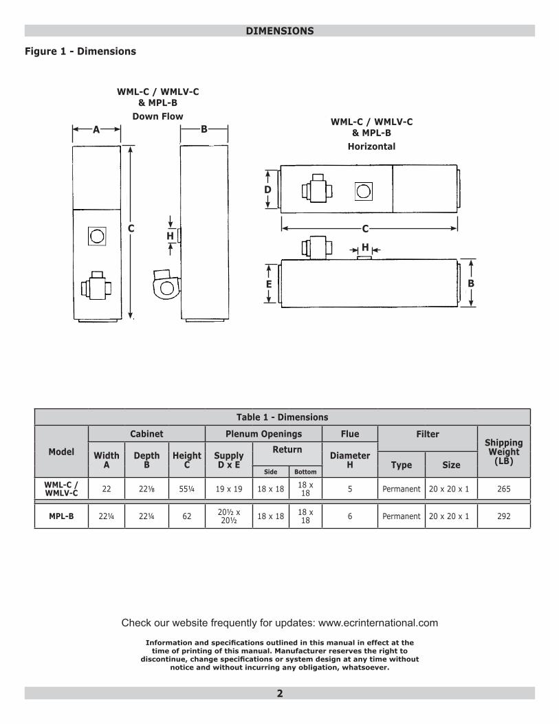
Table 1 - Dimensions
Model
Cabinet Plenum Openings Flue Filter Shipping Weight
(LB)WidthA
DepthB
HeightC
SupplyD x E
Return DiameterH Type Size
Side Bottom
WML-C /WMLV-C 22 22⅛ 55¼ 19 x 19 18 x 18 18 x
18 5 Permanent 20 x 20 x 1 265
MPL-B 22¼ 22¼ 62 20½ x 20½ 18 x 18 18 x
18 6 Permanent 20 x 20 x 1 292
D E
A B
CH
C
D
E B
H
WML-C / WMLV-C & MPL-B
Down Flow WML-C / WMLV-C & MPL-B
Horizontal
Check our website frequently for updates: www.ecrinternational.com
Information and specifications outlined in this manual in effect at thetime of printing of this manual. Manufacturer reserves the right to
discontinue, change specifications or system design at any time without notice and without incurring any obligation, whatsoever.
Figure 1 - Dimensions
3
TABLE OF CONTENTS
Dimensions ...............................................................................................................................21. General ................................................................................................................................42. Safety Symbols .....................................................................................................................43. Introduction ..........................................................................................................................44. Heat Loss .............................................................................................................................45. Locating The Unit ..................................................................................................................56. Down-Flow Installation ..........................................................................................................57. Horizontal Installation ...........................................................................................................58. Non-Suspended Installation ....................................................................................................59. Suspended Installation ...........................................................................................................510. Furnace Used In Conjunction With Air Conditioning ...................................................................511. Combustion Air ....................................................................................................................712. Chimney Venting ..................................................................................................................713. Barometric Damper Control ...................................................................................................914. Optional Side Wall Venting ....................................................................................................915a. Fan Timer Board And Limit Control (WML And MPL). ....................................................................915b. Fan Timer Board And Limit Control (WMLV) ...........................................................................916. Electrical Connections..........................................................................................................1017. Humidifier .........................................................................................................................1018. Piping Installation ..............................................................................................................1019. Oil Filter ...........................................................................................................................1020. Oil Burner Nozzles ..............................................................................................................1021. Oil Burner Adjustment ........................................................................................................1022. Burner Electrodes...............................................................................................................1123. Burner Primary (Safety) Control ...........................................................................................1124. Combustion Chamber .........................................................................................................1125a. Circulating Air Blower (WML/WMLV/MPL) .........................................................................................................1125b. Circulating Air Blower (WMLV) ...........................................................................................1226. Maintenance And Service ....................................................................................................1227. Operating Instructions (WML And MPL) .................................................................................1328. Operating Instructions (WMLV) ............................................................................................13Appendix A - Check Out And Adjustments ............................................................................ 14A.1 Oil Burner Air Adjustment ...................................................................................................15A.2 Burner Electrodes ..............................................................................................................16A.3 Start Up ...........................................................................................................................16A.4 Special Instructions For Units Equipped With Riello Burners .....................................................17A.5 Final Check Out .................................................................................................................17Appendix B: Wiring Diagrams ............................................................................................... 20Chimney Vent Furnace Wiring Diagram WML/WMLV/MPL ...............................................................20Direct Vent Furnace Wiring Diagram WML/WMLV/MPL ..................................................................21Appendix C - Sequence Of Operation And Troubleshooting ................................................... 22C.1 Troubleshooting .................................................................................................................23C.2 Preliminary Steps: .............................................................................................................23C.3 Check Oil Primary Control ...................................................................................................23Appendix D - Homeowner’s Reference Table ........................................................................ 27Parts Listing - Models WML And WMLV - Series C .........................................................................28Parts Listing - Vestibule Kit : WML And WMLV - Series C ...............................................................30Parts Listing - Diagram: WML And WMLV- Series C .......................................................................31Parts Listing - Models MPL - Series B ..........................................................................................32Parts Listing - Diagram: Models MPL - Series B ............................................................................34
4
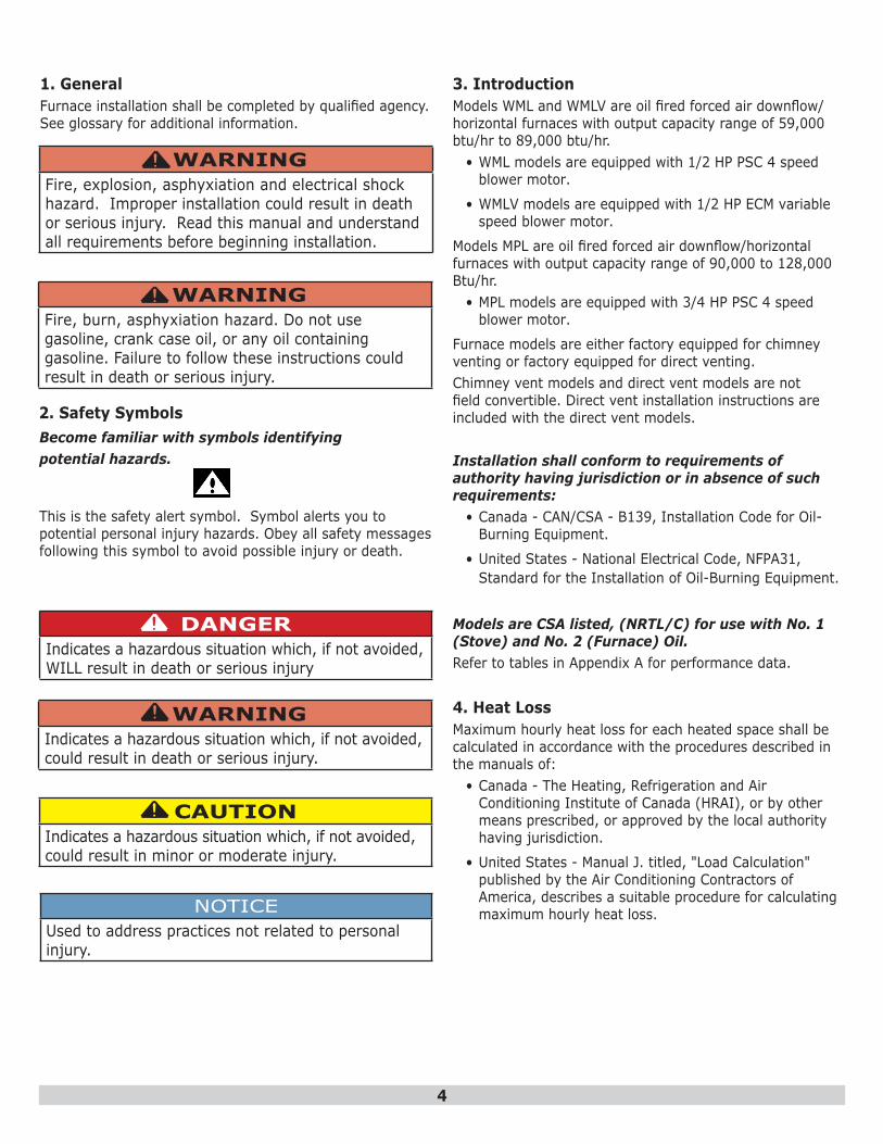
3. IntroductionModels WML and WMLV are oil fired forced air downflow/horizontal furnaces with output capacity range of 59,000 btu/hr to 89,000 btu/hr.
• WML models are equipped with 1/2 HP PSC 4 speed blower motor.
• WMLV models are equipped with 1/2 HP ECM variable speed blower motor.
Models MPL are oil fired forced air downflow/horizontal furnaces with output capacity range of 90,000 to 128,000 Btu/hr.
• MPL models are equipped with 3/4 HP PSC 4 speed blower motor.
Furnace models are either factory equipped for chimney venting or factory equipped for direct venting. Chimney vent models and direct vent models are not field convertible. Direct vent installation instructions are included with the direct vent models.
Installation shall conform to requirements of authority having jurisdiction or in absence of such requirements:
• Canada - CAN/CSA - B139, Installation Code for Oil-Burning Equipment.
• United States - National Electrical Code, NFPA31, Standard for the Installation of Oil-Burning Equipment.
Models are CSA listed, (NRTL/C) for use with No. 1 (Stove) and No. 2 (Furnace) Oil. Refer to tables in Appendix A for performance data.
4. Heat LossMaximum hourly heat loss for each heated space shall be calculated in accordance with the procedures described in the manuals of:
• Canada - The Heating, Refrigeration and Air Conditioning Institute of Canada (HRAI), or by other means prescribed, or approved by the local authority having jurisdiction.
• United States - Manual J. titled, "Load Calculation" published by the Air Conditioning Contractors of America, describes a suitable procedure for calculating maximum hourly heat loss.
1. GeneralFurnace installation shall be completed by qualified agency. See glossary for additional information.
WARNINGFire, explosion, asphyxiation and electrical shock hazard. Improper installation could result in death or serious injury. Read this manual and understand all requirements before beginning installation.
!
NOTICEUsed to address practices not related to personal injury.
CAUTIONIndicates a hazardous situation which, if not avoided, could result in minor or moderate injury.
!
WARNINGIndicates a hazardous situation which, if not avoided, could result in death or serious injury.
!
DANGERIndicates a hazardous situation which, if not avoided, WILL result in death or serious injury
!
This is the safety alert symbol. Symbol alerts you to potential personal injury hazards. Obey all safety messages following this symbol to avoid possible injury or death.
Become familiar with symbols identifyingpotential hazards.
2. Safety Symbols
WARNINGFire, burn, asphyxiation hazard. Do not use gasoline, crank case oil, or any oil containing gasoline. Failure to follow these instructions could result in death or serious injury.
!
5
5. Locating the Unit - [See Table 1]• Locate furnace so flue connection to chimney is short,
direct and consists of as few elbows as possible.
• Centralize furnace location with respect to supply and return air ductwork. Central location minimizes trunk duct sizing.
• All models may be installed on combustible floors.
WARNINGFire hazard. Do not install boiler on carpeting or tile floors. Failure to follow these instructions could result in death or serious injury.
!
• Do not install furnace on carpet or tiled floors.
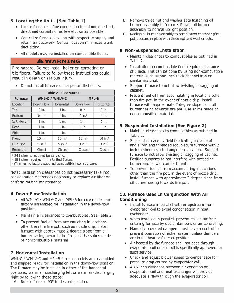
Table 2 - ClearancesFurnace WML-C / WMLV-C MPL-B
Location Down Flow Horizontal Down Flow HorizontalTop 0 in. 3 in. 0 in. 3 in.Bottom 0 in.3 1 in. 0 in.3 1 in.S/A Plenum 1 in. 1 in. 1 in. 1 in.Rear 1 in. 1 in. 1 in. 1 in.Sides 1 in. 1 in. 1 in. 1 in.Front 10 in.1 10 in.1 10 in.1 10 in.1
Flue Pipe 9 in. 2 9 in. 2 9 in. 2 9 in. 2
Enclosure Closet Closet Closet Closet1 24 inches is required for servicing.2 18 inches required in the United States.3 When using factory supplied combustible floor sub base.
Note: Installation clearances do not necessarily take into consideration clearances necessary to replace air filter or perform routine maintenance.
6. Down-Flow Installation • All WML-C / WMLV-C and MPL-B furnace models are
factory assembled for installation in the down-flow position.
• Maintain all clearances to combustibles. See Table 2.
• To prevent fuel oil from accumulating in locations other than the fire pot, such as nozzle drip, install furnace with approximate 2 degree slope from oil burner casing towards the fire pot. Use shims made of noncombustible material
7. Horizontal Installation WML-C / WMLV-C and MPL-B furnace models are assembled and shipped ready for installation in the down-flow position. The furnace may be installed in either of the horizontal positions; warm air discharging left or warm air-discharging right by following these steps:
A. Rotate furnace 90° to desired position.
B. Remove three nut and washer sets fastening oil burner assembly to furnace. Rotate oil burner assembly to normal upright position.
C. Realign oil burner assembly to combustion chamber (fire-pot), secure in place with three nut and washer sets.
8. Non-Suspended Installation • Maintain clearances to combustibles as outlined in
Table 2. • Installation on combustible floor requires clearance
of 1 inch. This can be done by using non-combustible material such as one-inch thick channel iron or similar material.
• Support furnace to not allow twisting or sagging of cabinet.
• Prevent fuel oil from accumulating in locations other than fire pot, in the event of nozzle drip, install furnace with approximate 2 degree slope from oil burner casing towards fire pot. Use shims made of noncombustible material.
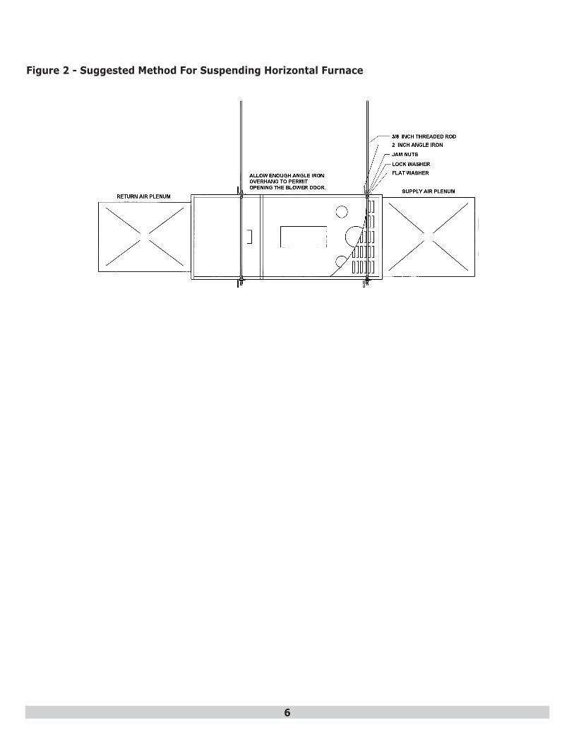
9. Suspended Installation (See Figure 2)• Maintain clearances to combustibles as outlined in
Table 2. • Suspend furnace by field fabricating a cradle of
angle iron and threaded rod. Secure furnace with 2 inch minimum slotted angle or equivalent. Support furnace to not allow twisting or sagging of cabinet. Position supports to not interfere with accessing burner and blower compartments.
• To prevent fuel oil from accumulating in locations other than the fire pot, in the event of nozzle drip, install furnace with approximate 2 degree slope from oil burner casing towards fire pot.
10. Furnace Used In Conjunction With Air Conditioning
• Install furnace in parallel with or upstream from evaporator coil to avoid condensation in heat exchanger.
• When installed in parallel, prevent chilled air from entering furnace by use of dampers or air controlling.
• Manually operated dampers must have a control to prevent operation of either system unless dampers are in full heat or full cool position.
• Air heated by the furnace shall not pass through evaporator coil unless coil is specifically approved for such service.
• Check and adjust blower speed to compensate for pressure drop caused by evaporator coil.
• A six inch clearance between air conditioning evaporator coil and heat exchanger will provide adequate airflow through the evaporator coil.
6
Figure 2 - Suggested Method For Suspending Horizontal Furnace
7
11. Combustion Air• Furnace installed in a closet or utility room, provide
two openings connecting to well-ventilated space (full basement, living room or other room opening, not a bedroom or bathroom).
• One opening shall be located above level of upper vent opening.
• One opening below combustion air inlet opening in front of furnace.
• Each opening shall have a minimum free area of 1½ square inches per 1,000 Btu/h of total input rating of all appliances installed in the room.
• For furnaces located in buildings of unusually tight construction, such as those with high quality weather stripping, caulking, windows and doors, or storm sashed windows, or where basement windows are well sealed, a permanent opening communicating with a well ventilated attic or with the outdoors shall be provided, using a duct if necessary. The duct opening shall have a free area of 1½ square inches per 1,000 Btu/h of total input rating of all appliances to be installed.
• Furnace installed in a full basement, infiltration is normally adequate to provide air for combustion and draft operation.
• Furnace rooms under 65m³ (700 ft³) should automatically be treated as confined space.
12. Chimney Venting WARNING
Asphyxiation hazard. Chimney vented versions of furnace must be connected to flue having sufficient draft at all times. Failure to follow these instructions could result in death or serious injury.
!
Chimney must be sized correctly and in good repair. There is a risk of flue gases condensing resulting in damage to chimney and other venting parts with oversized chimney. Problem may be corrected by use of appropriately sized chimney liner.If chimney serves WML-C and WMLV-C furnaces only, size vent at 5-inch minimum. Size MPL-B at 6-inch minimum. Data provided in Table 4 is based on dedicated venting. If furnace is to be co-vented with other appliances, refer to:
NFPA 211, Standard for Chimneys, Fire-places, Vents, and Solid Fuel-Burning Appliances, NFPA 31, Standard for the Installation of Oil-Burning Equipment or CAN/CSA B139, Installation Code For Oil-Burning Equipment for correct sizing information.
Test chimney under “winter” conditions; doors and windows closed, all other fossil fuel burning appliances on, clothes dryer on, bathroom fans on, etc. If chimney cannot over-come competition for air, assess the reason, and take corrective action. If chimney is found to be sized correctly and in good repair, re-evaluate the availability of combustion and ventilation air, and take corrective action.
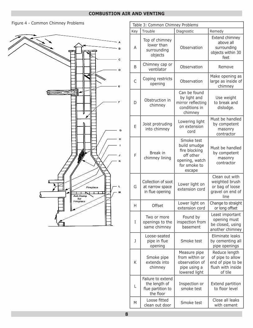
See Figure 4 and Table 3 for common chimney problems and remedies.
• Flue pipe should be as short as possible with horizontal pipes sloping upward toward the chimney at a rate of one-quarter inch per foot.
• Flue pipe should not be smaller in cross sectional area than flue collar on the furnace.
• Flue pipe should connect to chimney so the flue pipe extends into, and terminates flush with the inside surface of chimney liner. Seal the joint between pipe and lining.
• Chimney outlet should be at least two feet above highest point of peaked roof.
• All unused chimney openings should be closed. • Chimneys must conform to local, provincial or state
codes, or in the absence of local regulations, to the requirements of the National Building Code.
NOTICEThis furnace is approved for use with Type L vent or equivalent. Maximum temperature for L vent is 575°F (300C).
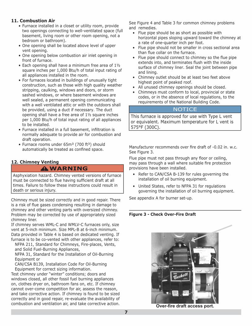
Manufacturer recommends over fire draft of -0.02 in. w.c. See Figure 3.Flue pipe must not pass through any floor or ceiling, may pass through a wall where suitable fire protection provisions have been installed.
• Refer to CAN/CSA B-139 for rules governing the installation of oil burning equipment.
• United States, refer to NFPA 31 for regulations governing the installation of oil burning equipment.
See appendix A for burner set-up.
Figure 3 - Check Over-Fire Draft
Over-fire draft access port.
8
COMBUSTION AIR AND VENTING
Table 3: Common Chimney ProblemsKey Trouble Diagnostic Remedy
A
Top of chimney lower than surrounding
objects
Observation
Extend chimney above all
surrounding objects within 30
feet
B Chimney cap or ventilator Observation Remove
C Coping restricts opening Observation
Make opening as large as inside of
chimney
D Obstruction in chimney
Can be found by light and
mirror reflecting conditions in
chimney
Use weight to break and
dislodge.
E Joist protruding into chimney
Lowering light on extension
cord
Must be handled by competent
masonry contractor
F Break in chimney lining
Smoke test build smudge fire blocking
off other opening, watch for smoke to
escape
Must be handled by competent
masonry contractor
GCollection of soot at narrow space in flue opening
Lower light on extension cord
Clean out with weighted brush or bag of loose gravel on end of
line
H Offset Lower light on extension cord
Change to straight or long offset
ITwo or more
openings to the same chimney
Found by inspection from
basement
Least important opening must
be closed, using another chimney
JLoose-seated pipe in flue
openingSmoke test
Eliminate leaks by cementing all pipe openings
KSmoke pipe extends into
chimney
Measure pipe from within or observation of pipe using a lowered light
Reduce length of pipe to allow
end of pipe to be flush with inside
of tile
L
Failure to extend the length of
flue partition to the floor
Inspection or smoke test
Extend partition to floor level
M Loose fitted clean out door Smoke test Close all leaks
with cement
Figure 4 - Common Chimney Problems
9
COMBUSTION AIR AND VENTING
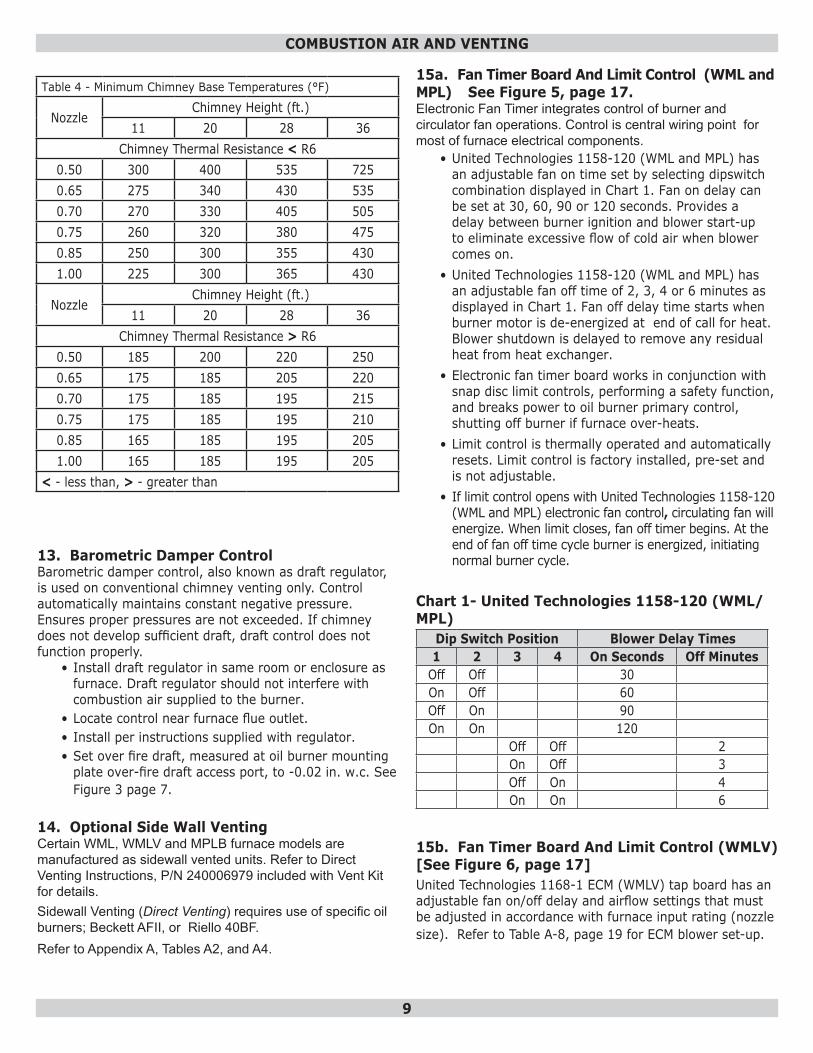
Table 4 - Minimum Chimney Base Temperatures (°F)
NozzleChimney Height (ft.)
11 20 28 36Chimney Thermal Resistance < R6
0.50 300 400 535 7250.65 275 340 430 5350.70 270 330 405 5050.75 260 320 380 4750.85 250 300 355 4301.00 225 300 365 430
NozzleChimney Height (ft.)
11 20 28 36Chimney Thermal Resistance > R6
0.50 185 200 220 2500.65 175 185 205 2200.70 175 185 195 2150.75 175 185 195 2100.85 165 185 195 2051.00 165 185 195 205
< - less than, > - greater than
13. Barometric Damper ControlBarometric damper control, also known as draft regulator, is used on conventional chimney venting only. Control automatically maintains constant negative pressure. Ensures proper pressures are not exceeded. If chimney does not develop sufficient draft, draft control does not function properly.
• Install draft regulator in same room or enclosure as furnace. Draft regulator should not interfere with combustion air supplied to the burner.
• Locate control near furnace flue outlet. • Install per instructions supplied with regulator. • Set over fire draft, measured at oil burner mounting
plate over-fire draft access port, to -0.02 in. w.c. See Figure 3 page 7.
14. Optional Side Wall VentingCertain WML, WMLV and MPLB furnace models are manufactured as sidewall vented units. Refer to Direct Venting Instructions, P/N 240006979 included with Vent Kit for details. Sidewall Venting (Direct Venting) requires use of specific oil burners; Beckett AFII, or Riello 40BF. Refer to Appendix A, Tables A2, and A4.
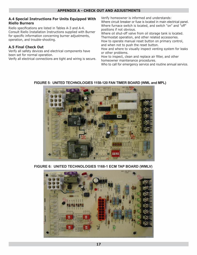
15a. Fan Timer Board And Limit Control (WML and MPL) See Figure 5, page 17.Electronic Fan Timer integrates control of burner and circulator fan operations. Control is central wiring point for most of furnace electrical components.
• United Technologies 1158-120 (WML and MPL) has an adjustable fan on time set by selecting dipswitch combination displayed in Chart 1. Fan on delay can be set at 30, 60, 90 or 120 seconds. Provides a delay between burner ignition and blower start-up to eliminate excessive flow of cold air when blower comes on.
• United Technologies 1158-120 (WML and MPL) has an adjustable fan off time of 2, 3, 4 or 6 minutes as displayed in Chart 1. Fan off delay time starts when burner motor is de-energized at end of call for heat. Blower shutdown is delayed to remove any residual heat from heat exchanger.
• Electronic fan timer board works in conjunction with snap disc limit controls, performing a safety function, and breaks power to oil burner primary control, shutting off burner if furnace over-heats.
• Limit control is thermally operated and automatically resets. Limit control is factory installed, pre-set and is not adjustable.
• If limit control opens with United Technologies 1158-120 (WML and MPL) electronic fan control, circulating fan will energize. When limit closes, fan off timer begins. At the end of fan off time cycle burner is energized, initiating normal burner cycle.
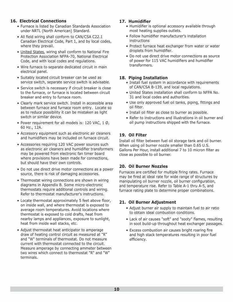
Chart 1- United Technologies 1158-120 (WML/MPL)
Dip Switch Position Blower Delay Times1 2 3 4 On Seconds Off Minutes
Off Off 30On Off 60Off On 90On On 120
Off Off 2On Off 3Off On 4On On 6
15b. Fan Timer Board And Limit Control (WMLV) [See Figure 6, page 17]United Technologies 1168-1 ECM (WMLV) tap board has an adjustable fan on/off delay and airflow settings that must be adjusted in accordance with furnace input rating (nozzle size). Refer to Table A-8, page 19 for ECM blower set-up.
10
16. Electrical Connections• Furnace is listed by Canadian Standards Association
under NRTL (North American) Standard. • All field wiring shall conform to CAN/CSA C22.1
Canadian Electrical Code, Part 1, and by local codes, where they prevail.
• United States, wiring shall conform to National Fire Protection Association NFPA-70, National Electrical Code, and with local codes and regulations.
• Wire furnace to separate dedicated circuit in main electrical panel.
• Suitably located circuit breaker can be used as service switch, separate service switch is advisable.
• Service switch is necessary if circuit breaker is close to the furnace, or furnace is located between circuit breaker and entry to furnace room.
• Clearly mark service switch. Install in accessible area between furnace and furnace room entry. Locate so as to reduce possibility it can be mistaken as light switch or similar device.
• Power requirement for all models is: 120 VAC, 1 Ø, 60 Hz., 12A.
• Accessory equipment such as electronic air cleaners and humidifiers may be included on furnace circuit.
• Accessories requiring 120 VAC power sources such as electronic air cleaners and humidifier transformers may be powered from electronic fan timer board where provisions have been made for connections, but should have their own controls.
• Do not use direct drive motor connections as a power source, there is risk of damaging accessories.
• Thermostat wiring connections are shown in wiring diagrams in Appendix B. Some micro-electronic thermostats require additional controls and wiring. Refer to thermostat manufacturer's instructions.
• Locate thermostat approximately 5 feet above floor, on inside wall, and where thermostat is exposed to average room temperatures. Avoid locations where thermostat is exposed to cold drafts, heat from nearby lamps and appliances, exposure to sunlight, heat from inside wall stacks, etc.
• Adjust thermostat heat anticipator to amperage draw of heating control circuit as measured at "R" and "W" terminals of thermostat. Do not measure current with thermostat connected to the circuit. Measure amperage by connecting ammeter between two wires which connect to thermostat "R" and "W" terminals.
17. Humidifier• Humidifier is optional accessory available through
most heating supplies outlets. • Follow humidifier manufacturer's installation
instructions• Protect furnace heat exchanger from water or water
droplets from humidifier.• Do not use direct drive motor connections as source
of power for 115 VAC humidifiers and humidifier transformers.
18. Piping Installation• Install fuel system in accordance with requirements
of CAN/CSA B-139, and local regulations. • United States installation shall conform to NFPA No.
31 and local codes and authorities.• Use only approved fuel oil tanks, piping, fittings and
oil filter.• Install oil filter as close to burner as possible. • Refer to instructions and illustrations in oil burner and
oil pump instructions shipped with the furnace.
19. Oil FilterInstall oil filter between fuel oil storage tank and oil burner. When using oil burner nozzle smaller than 0.65 U.S. Gallons Per Hour, install additional 7 to 10 micron filter as close as possible to oil burner.
20. Oil Burner NozzlesFurnaces are certified for multiple firing rates. Furnace may be fired at ideal rate for wide range of structures by manipulating oil burner nozzle, oil burner configuration, and temperature rise. Refer to Table A-1 thru A-5, and furnace rating plate to determine proper combinations.
21. Oil Burner Adjustment• Adjust burner air supply to maintain fuel to air ratio
to obtain ideal combustion conditions.
• Lack of air causes "soft" and "sooty" flames, resulting in soot build-up throughout heat exchanger passages.
• Excess combustion air causes bright roaring fire and high stack temperatures resulting in poor fuel efficiency.
11
• Oil furnaces operate most efficiently with No. 1 smoke spot on Bacharach Scale. Dust will eventually build up on air moving components of oil burner assembly resulting in decreased air supply with potential soot build up in flue gas passageways of heat exchanger. Soot behaves as insulator and impairs good heat transfer. Stack temperature increases, and efficiency decreases. To avoid this problem, adjust the air supply to provide no more than trace smoke spot on Bacharach Scale.
• See Venting Instructions included in Vent Kits for set-up details for sidewall vented furnaces.
NOTICESet up sidewall vented models to deliver zero (0) smoke.
NOTICEBefore operating furnace check burner alignment with combustion chamber. End cone of air tube must be centred to accommodating ring of combustion chamber. Adjust as necessary.
22. Burner ElectrodesCorrect positioning of electrode tips with respect to each other, fuel oil nozzle, and burners is essential for smooth light ups and proper operation. Refer to oil burner instructions provided with furnace and Appendix A Section A.2 in this manual for electrode specifications.
NOTICEDo not tamper with furnace controls they are sensitive. If problems persist, call your service contractor.
23. Burner Primary (Safety) ControlFurnace is equipped with primary combustion control, also referred to as burner relay or burner protector relay, which uses a cad cell located in burner housing, to monitor and control combustion. Dust or combustion residuals can build up on lens of cad cell impairing its response to flame. Check cad cell for cleanliness and proper alignment if primary control frequently shuts down combustion.
24. Combustion Chamber
Furnace is equipped with cerafelt combustion chamber, held in place by a retaining bracket.Check the alignment of the combustion chamber and oil burner before firing. It is possible for the combustion chamber to shift if subjected to rough handling during transit.
Inspect combustion chamber for damage or carbon build up whenever oil burner is removed for repairs or routine maintenance.
WARNINGFire, burn, asphyxiation hazard. Do not start the burner unless blower access door is secured in place. Failure to follow these instructions could result in death or serious injury.
!
25a. Circulating Air Blower (WML/WMLV/MPL)• Furnace models are equipped with direct drive blower
systems. • WML and MPL models are equipped with PSC motors.• WMLV models are equipped with electronically
commutated motors (ECM).
Direct Drive Blower Systems• Direct drive blower speed adjustments are not
normally required in properly sized extended plenum duct systems. Motor RPM and air CFM delivery will vary automatically to accommodate conditions within usual range of external static pressures typical of residential duct systems.
• Under-sized duct systems may require higher blower speed to obtain system temperature rise.
• Some older duct systems were not designed to provide static pressure. They typically feature special reducing fittings at each branch run and lack block ends on trunk ducts. These systems may require modification to provide some resistance to the airflow to prevent over-amping of direct drive blower motor. Selecting a lower blower speed may correct this problem.
• Direct drive blower speeds are adjusted by changing"hot" wires to motor winding connections. Refer to wiring diagrams in Appendix B or wiring diagram label affixed to furnace.
• Do not move neutral wire (normally white wire) to adjust blower speed.
• Single blower speed for both heating and cooling modes may be used. Use a "piggy-back connector" accommodating both wires on a single motor tap.
• It is also acceptable to connect selected motor speed with a pigtail joined to both heating and cooling speed wires with a wire nut.
• Safety precaution against accidental disconnection of wires by vibration, secure wire nut and wires with few wraps of electricians tape.
• Do not connect power leads between motor speeds. Always connect neutral wire to motor's designated neutral terminal.
12
WARNINGElectrical shock hazard. Turn OFF electrical power supply at service panel before opening blower access door. Failure to do so could result in death or serious injury.
!
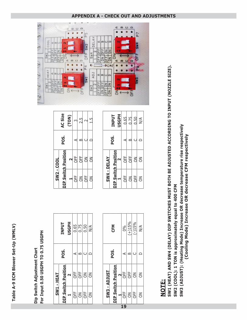
25b. Circulating Air Blower (WMLV) WMLV furnace models are equipped with electronically commutated motors (ECM). Setting Blower Speed and “ON” and “OFF” TimingsBlower speed and on/off time delays are handled by ECM motor programming and are set via dipswitches per Table A-9 on page 19. Heating airflow rate is SW1 and on/off delay is SW4, both are set according to firing rate. Cooling airflow rate is SW2 and if used is set according to installed cooling capacity. SW3 can be used to adjust airflow rate by (+) or (-) 15%. Features of this ECM variable speed motor are that it will deliver a constant airflow within a wide range of external static pressures, and also includes:
• Soft Start: ECM will slowly ramp up to required operating speed. In heating cycle allows heat exchanger to reach operating temperature before set heat speed, minimizes noise and increases comfort.
• Soft Stop: At end of heating cycle, ECM will slowly ramp down. Allows increased energy efficiency and reduced noise levels.
• Dehumidification: Dehumidification feature is programmed into the variable speed motor. At start of each cooling cycle, variable speed motor will run at 82% of rated airflow for 7.5 minutes. After 7.5 minutes has elapsed, motor will increase to 100% of rated airflow. Used to provide dehumidification and improve system efficiency.
• Continuous Fan Operation: When thermostat continuous fan (G) switch is on without call for heating or cooling, indoor fan is immediately energized up to 50% of cooling speed. Allows continuous circulation of air between calls for heating or cooling. If call for heat (W) or cool (Y) occurs during continuous fan, blower remains energized.
26. Maintenance And ServiceRoutine Maintenance By Home Owner
• Arrange for professional servicing of furnace by the service or installation contractor annually.
• Homeowner is to maintain air filter or filters. A dirty filter can cause furnace to over-heat, fail to maintain indoor temperature during cold weather, increase fuel consumption and cause component failure.
• Inspect, clean or replace filter monthly.
• Furnace is supplied with semi-permanent type filter. If filter is damaged, replace with filters of same size and type.
• During monthly filter inspection, inspect general condition of furnace. Watch for signs of oil leaks in vicinity of oil burner, soot forming on any external part of furnace, soot forming around joints in vent pipe, etc. If any of these conditions are present, please advise your service or installation contractor.
Annual Service By Contractor
NOTICECombustion chamber (firepot) is fragile. Use care when inspecting and cleaning this area
• Inspect heat exchanger periodically and clean if necessary.
WARNINGElectrical shock hazard. Turn OFF electrical power supply at service panel before service or maintenance Failure to do so could result in death or serious injury.
!
• If cleaning is necessary, shut off oil supply, shut off power to the furnace and remove burner.
• Use stiff brush with wire handle, brush off scale and soot from inside drum and flue pipe.
• Clean radiator, remove clean-out cap screws. Remove caps carefully to avoid tearing gaskets.
• Wire brush can be used to loosen dirt and debris on the inside surfaces of radiator. Clean out all accumulated dirt, soot and debris with a wire handled brush and an industrial vacuum cleaner.
• Before replacing clean-out caps, inspect gaskets. If gaskets are broken, remove remnants and replace with new gaskets.
• Blower motor is factory oiled and permanently sealed. Do not lubricate. Excess oil causes premature electric motor failure.
• Inspect blower fan. Clean if necessary.• Oil Burner Maintenance: Follow oil burner
manufacturer instructions. • Change oil burner nozzle and oil filter annually.
• If joining blower speed wiring is done in furnace junction box, tape off both ends of unused wire.
• Do not use blower speed wires as source of power to accessories as electronic air cleaners and humidifier transformers. Unused motor taps auto-generate sufficiently high voltages to damage accessory equipment.
13
27. Operating Instructions (WML And MPL)Before Lighting1. Open all supply and return air registers and grilles.2. Open all valves in oil pipes.3. Turn on electric power supply
To Light Unit1. Set thermostat above room temperature to call for
heat. Burner should start. It may be necessary to press RESET button on primary combustion control relay.
2. There is a fan on time delay before circulating fan is energized. United Technologies 1158-120 has adjustable fan on time set by selecting dipswitch combination displayed in Chart 1. Fan on delay can be set at 30, 60, 90 or 120 seconds.
3. Set the thermostat below room temperature. Oil burner stops.
4. Air circulation blower continues to operate until time off setting selected on electronic fan timer control times out. United Technologies 1158-120 has adjustable fan off time of 2, 3, 4 or 6 minutes. Fan timer control adjustments may be altered if air at room registers is high upon blower start up or shutdown.
5. Restore thermostat setting to comfortable temperature.
To Shut Down Unit1. Set thermostat to lowest possible setting.2. Set manual switch (if installed) in electrical power
supply line to "OFF".
28. Operating Instructions (WMLV)Before Lighting1. Open all supply and return air registers and grilles.2. Open all valves in oil pipes.3. Turn on electric power supply.
To Light Unit1. Set thermostat above room temperature to call for
heat. Burner should start. It may be necessary to press RESET button on primary combustion control relay.
2. There is a fan on time delay before circulating fan is energized. United Technologies 1168-1 has adjustable fan on/off time delay programmed into ECM motor, and is set by selecting SW4 DIP switch combination displayed in Table A-9 page 19. Adjust Fan on/off delay according to input (nozzle size).
3. Set thermostat below room temperature. Oil burner stops.
4. Air circulation blower continues to operate until blower off delay setting programmed into ECM motor times out.
5. Restore thermostat setting to comfortable temperature.
NOTICEIf furnace is to be shut down for extended period of time, close oil supply valve to burner.
WARNINGFire, burn, explosion, asphyxiation hazard. • Do not start burner when excess oil has
accumulated, furnace is full of vapor, or combustion chamber is very hot.
• Do not burn garbage or paper in furnace. • Do not leave paper or rags around furnace.
Failure to follow these instructions could result in death or serious injury.
!
• Clean and inspect venting system for signs of deterioration. Replace pitted or perforated vent pipe and fittings.
• Barometric damper should open and close freely.• Check electrical connections to ensure tight
connections. Safety controls such as the high limit controls should be tested for functionality.
• Check fan control to ensure fan on and off delay function continues to start and stop blower fan at optimal settings.
14
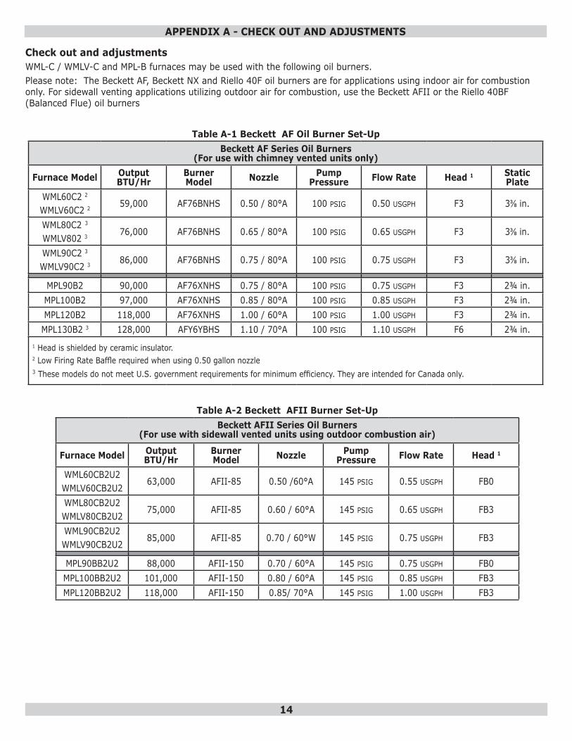
Check out and adjustmentsWML-C / WMLV-C and MPL-B furnaces may be used with the following oil burners.Please note: The Beckett AF, Beckett NX and Riello 40F oil burners are for applications using indoor air for combustion only. For sidewall venting applications utilizing outdoor air for combustion, use the Beckett AFII or the Riello 40BF (Balanced Flue) oil burners
Table A-1 Beckett AF Oil Burner Set-UpBeckett AF Series Oil Burners
(For use with chimney vented units only)
Furnace Model Output BTU/Hr
Burner Model Nozzle Pump
Pressure Flow Rate Head 1 Static Plate
WML60C2 2
WMLV60C2 2 59,000 AF76BNHS 0.50 / 80°A 100 PSIG 0.50 USGPH F3 3⅜ in.
WML80C2 3
WMLV802 3 76,000 AF76BNHS 0.65 / 80°A 100 PSIG 0.65 USGPH F3 3⅜ in.
WML90C2 3
WMLV90C2 3 86,000 AF76BNHS 0.75 / 80°A 100 PSIG 0.75 USGPH F3 3⅜ in.
MPL90B2 90,000 AF76XNHS 0.75 / 80°A 100 PSIG 0.75 USGPH F3 2¾ in.MPL100B2 97,000 AF76XNHS 0.85 / 80°A 100 PSIG 0.85 USGPH F3 2¾ in.MPL120B2 118,000 AF76XNHS 1.00 / 60°A 100 PSIG 1.00 USGPH F3 2¾ in.
MPL130B2 3 128,000 AFY6YBHS 1.10 / 70°A 100 PSIG 1.10 USGPH F6 2¾ in.1 Head is shielded by ceramic insulator.2 Low Firing Rate Baffle required when using 0.50 gallon nozzle3 These models do not meet U.S. government requirements for minimum efficiency. They are intended for Canada only.
Table A-2 Beckett AFII Burner Set-UpBeckett AFII Series Oil Burners
(For use with sidewall vented units using outdoor combustion air)
Furnace Model Output BTU/Hr
Burner Model Nozzle Pump
Pressure Flow Rate Head 1
WML60CB2U2WMLV60CB2U2
63,000 AFII-85 0.50 /60°A 145 PSIG 0.55 USGPH FB0
WML80CB2U2WMLV80CB2U2
75,000 AFII-85 0.60 / 60°A 145 PSIG 0.65 USGPH FB3
WML90CB2U2WMLV90CB2U2
85,000 AFII-85 0.70 / 60°W 145 PSIG 0.75 USGPH FB3
MPL90BB2U2 88,000 AFII-150 0.70 / 60°A 145 PSIG 0.75 USGPH FB0MPL100BB2U2 101,000 AFII-150 0.80 / 60°A 145 PSIG 0.85 USGPH FB3MPL120BB2U2 118,000 AFII-150 0.85/ 70°A 145 PSIG 1.00 USGPH FB3
APPENDIX A - CHECK OUT AND ADJUSTMENTS
15
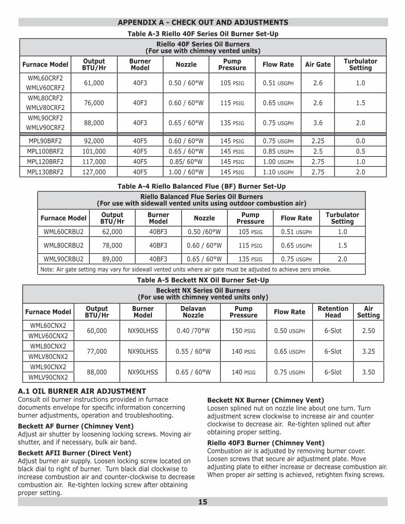
Table A-3 Riello 40F Series Oil Burner Set-UpRiello 40F Series Oil Burners
(For use with chimney vented units)
Furnace Model Output BTU/Hr
Burner Model Nozzle Pump
Pressure Flow Rate Air Gate Turbulator Setting
WML60CRF2WMLV60CRF2
61,000 40F3 0.50 / 60°W 105 PSIG 0.51 USGPH 2.6 1.0
WML80CRF2WMLV80CRF2
76,000 40F3 0.60 / 60°W 115 PSIG 0.65 USGPH 2.6 1.5
WML90CRF2WMLV90CRF2
88,000 40F3 0.65 / 60°W 135 PSIG 0.75 USGPH 3.6 2.0
MPL90BRF2 92,000 40F5 0.60 / 60°W 145 PSIG 0.75 USGPH 2.25 0.0MPL100BRF2 101,000 40F5 0.65 / 60°W 145 PSIG 0.85 USGPH 2.5 0.5MPL120BRF2 117,000 40F5 0.85/ 60°W 145 PSIG 1.00 USGPH 2.75 1.0MPL130BRF2 127,000 40F5 1.00 / 60°W 145 PSIG 1.10 USGPH 2.75 2.0
Table A-4 Riello Balanced Flue (BF) Burner Set-UpRiello Balanced Flue Series Oil Burners
(For use with sidewall vented units using outdoor combustion air)
Furnace Model Output BTU/Hr
Burner Model Nozzle Pump
Pressure Flow Rate Turbulator Setting
WML60CRBU2 62,000 40BF3 0.50 /60°W 105 PSIG 0.51 USGPH 1.0
WML80CRBU2 78,000 40BF3 0.60 / 60°W 115 PSIG 0.65 USGPH 1.5
WML90CRBU2 89,000 40BF3 0.65 / 60°W 135 PSIG 0.75 USGPH 2.0Note: Air gate setting may vary for sidewall vented units where air gate must be adjusted to achieve zero smoke.
A.1 OIL BURNER AIR ADJUSTMENTConsult oil burner instructions provided in furnace documents envelope for specific information concerning burner adjustments, operation and troubleshooting.Beckett AF Burner (Chimney Vent)Adjust air shutter by loosening locking screws. Moving air shutter, and if necessary, bulk air band.Beckett AFII Burner (Direct Vent)Adjust burner air supply. Loosen locking screw located on black dial to right of burner. Turn black dial clockwise to increase combustion air and counter-clockwise to decrease combustion air. Re-tighten locking screw after obtaining proper setting.
Beckett NX Burner (Chimney Vent)Loosen splined nut on nozzle line about one turn. Turn adjustment screw clockwise to increase air and counter clockwise to decrease air. Re-tighten splined nut after obtaining proper setting.Riello 40F3 Burner (Chimney Vent)Combustion air is adjusted by removing burner cover. Loosen screws that secure air adjustment plate. Move adjusting plate to either increase or decrease combustion air. When proper air setting is achieved, retighten fixing screws.
APPENDIX A - CHECK OUT AND ADJUSTMENTS
Table A-5 Beckett NX Oil Burner Set-UpBeckett NX Series Oil Burners
(For use with chimney vented units only)
Furnace Model Output BTU/Hr
Burner Model
Delavan Nozzle
Pump Pressure Flow Rate Retention
HeadAir
SettingWML60CNX2
60,000 NX90LHSS 0.40 /70°W 150 PSIG 0.50 USGPH 6-Slot 2.50WMLV60CNX2WML80CNX2
77,000 NX90LHSS 0.55 / 60°W 140 PSIG 0.65 USGPH 6-Slot 3.25WMLV80CNX2WML90CNX2
88,000 NX90LHSS 0.65 / 60°W 140 PSIG 0.75 USGPH 6-Slot 3.50WMLV90CNX2
16
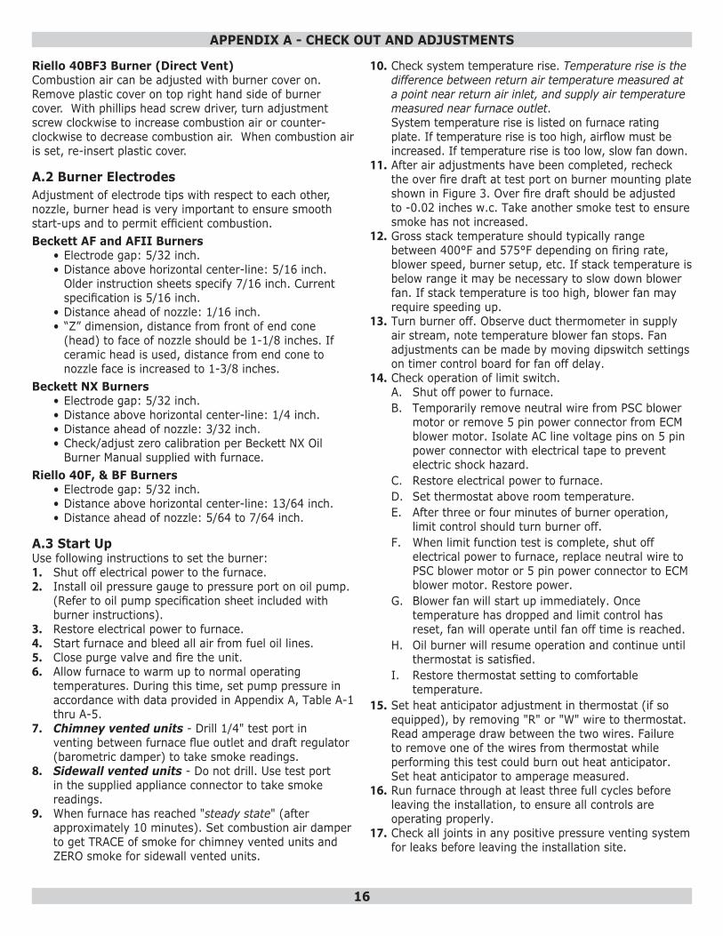
A.2 Burner ElectrodesAdjustment of electrode tips with respect to each other, nozzle, burner head is very important to ensure smooth start-ups and to permit efficient combustion.Beckett AF and AFII Burners
• Electrode gap: 5/32 inch.• Distance above horizontal center-line: 5/16 inch.
Older instruction sheets specify 7/16 inch. Current specification is 5/16 inch.
• Distance ahead of nozzle: 1/16 inch.• “Z” dimension, distance from front of end cone
(head) to face of nozzle should be 1-1/8 inches. If ceramic head is used, distance from end cone to nozzle face is increased to 1-3/8 inches.
Beckett NX Burners• Electrode gap: 5/32 inch.• Distance above horizontal center-line: 1/4 inch. • Distance ahead of nozzle: 3/32 inch.• Check/adjust zero calibration per Beckett NX Oil
Burner Manual supplied with furnace.Riello 40F, & BF Burners
• Electrode gap: 5/32 inch.• Distance above horizontal center-line: 13/64 inch. • Distance ahead of nozzle: 5/64 to 7/64 inch.
A.3 Start UpUse following instructions to set the burner:1. Shut off electrical power to the furnace.2. Install oil pressure gauge to pressure port on oil pump.
(Refer to oil pump specification sheet included with burner instructions).
3. Restore electrical power to furnace.4. Start furnace and bleed all air from fuel oil lines.5. Close purge valve and fire the unit.6. Allow furnace to warm up to normal operating
temperatures. During this time, set pump pressure in accordance with data provided in Appendix A, Table A-1 thru A-5.
7. Chimney vented units - Drill 1/4" test port in venting between furnace flue outlet and draft regulator (barometric damper) to take smoke readings.
8. Sidewall vented units - Do not drill. Use test port in the supplied appliance connector to take smoke readings.
9. When furnace has reached "steady state" (after approximately 10 minutes). Set combustion air damper to get TRACE of smoke for chimney vented units and ZERO smoke for sidewall vented units.
10. Check system temperature rise. Temperature rise is the difference between return air temperature measured at a point near return air inlet, and supply air temperature measured near furnace outlet. System temperature rise is listed on furnace rating plate. If temperature rise is too high, airflow must be increased. If temperature rise is too low, slow fan down.
11. After air adjustments have been completed, recheck the over fire draft at test port on burner mounting plate shown in Figure 3. Over fire draft should be adjusted to -0.02 inches w.c. Take another smoke test to ensure smoke has not increased.
12. Gross stack temperature should typically range between 400°F and 575°F depending on firing rate, blower speed, burner setup, etc. If stack temperature is below range it may be necessary to slow down blower fan. If stack temperature is too high, blower fan may require speeding up.
13. Turn burner off. Observe duct thermometer in supply air stream, note temperature blower fan stops. Fan adjustments can be made by moving dipswitch settings on timer control board for fan off delay.
14. Check operation of limit switch. A. Shut off power to furnace. B. Temporarily remove neutral wire from PSC blower
motor or remove 5 pin power connector from ECM blower motor. Isolate AC line voltage pins on 5 pin power connector with electrical tape to prevent electric shock hazard.
C. Restore electrical power to furnace. D. Set thermostat above room temperature. E. After three or four minutes of burner operation,
limit control should turn burner off. F. When limit function test is complete, shut off
electrical power to furnace, replace neutral wire to PSC blower motor or 5 pin power connector to ECM blower motor. Restore power.
G. Blower fan will start up immediately. Once temperature has dropped and limit control has reset, fan will operate until fan off time is reached.
H. Oil burner will resume operation and continue until thermostat is satisfied.
I. Restore thermostat setting to comfortable temperature.
15. Set heat anticipator adjustment in thermostat (if so equipped), by removing "R" or "W" wire to thermostat. Read amperage draw between the two wires. Failure to remove one of the wires from thermostat while performing this test could burn out heat anticipator. Set heat anticipator to amperage measured.
16. Run furnace through at least three full cycles before leaving the installation, to ensure all controls are operating properly.
17. Check all joints in any positive pressure venting system for leaks before leaving the installation site.
APPENDIX A - CHECK OUT AND ADJUSTMENTS
Riello 40BF3 Burner (Direct Vent)Combustion air can be adjusted with burner cover on. Remove plastic cover on top right hand side of burner cover. With phillips head screw driver, turn adjustment screw clockwise to increase combustion air or counter-clockwise to decrease combustion air. When combustion air is set, re-insert plastic cover.
17
A.5 Final Check OutVerify all safety devices and electrical components have been set for normal operation. Verify all electrical connections are tight and wiring is secure.
FIGURE 5: UNITED TECHNOLOGIES 1158-120 FAN TIMER BOARD (WML and MPL)
FIGURE 6: UNITED TECHNOLOGIES 1168-1 ECM TAP BOARD (WMLV)
Verify homeowner is informed and understands:Where circuit breaker or fuse is located in main electrical panel.Where furnace switch is located, and switch "on" and "off" positions if not obvious.Where oil shut-off valve from oil storage tank is located.Thermostat operation, and other related accessories.How to operate manual reset button on primary control, and when not to push the reset button.How and where to visually inspect venting system for leaks or other problems.How to inspect, clean and replace air filter, and other homeowner maintenance procedures.Who to call for emergency service and routine annual service.
APPENDIX A - CHECK OUT AND ADJUSTMENTS
A.4 Special Instructions For Units Equipped With Riello BurnersRiello specifications are listed in Tables A-3 and A-4. Consult Riello Installation Instructions supplied with Burner for specific information concerning burner adjustments, operation, and trouble-shooting.
18
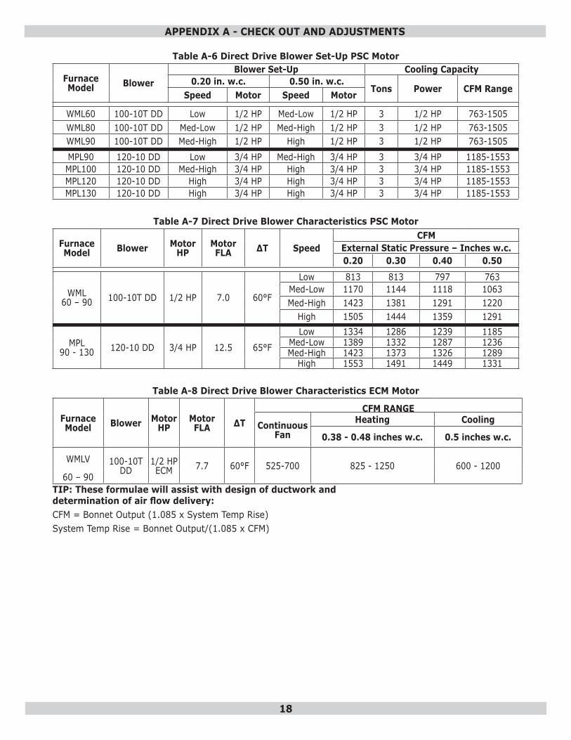
Table A-6 Direct Drive Blower Set-Up PSC Motor
Furnace Model Blower
Blower Set-Up Cooling Capacity0.20 in. w.c. 0.50 in. w.c.
Tons Power CFM RangeSpeed Motor Speed Motor
WML60 100-10T DD Low 1/2 HP Med-Low 1/2 HP 3 1/2 HP 763-1505WML80 100-10T DD Med-Low 1/2 HP Med-High 1/2 HP 3 1/2 HP 763-1505WML90 100-10T DD Med-High 1/2 HP High 1/2 HP 3 1/2 HP 763-1505MPL90 120-10 DD Low 3/4 HP Med-High 3/4 HP 3 3/4 HP 1185-1553MPL100 120-10 DD Med-High 3/4 HP High 3/4 HP 3 3/4 HP 1185-1553MPL120 120-10 DD High 3/4 HP High 3/4 HP 3 3/4 HP 1185-1553MPL130 120-10 DD High 3/4 HP High 3/4 HP 3 3/4 HP 1185-1553
Table A-7 Direct Drive Blower Characteristics PSC Motor
Furnace Model Blower Motor
HPMotor FLA ∆T Speed
CFMExternal Static Pressure – Inches w.c.0.20 0.30 0.40 0.50
WML60 – 90 100-10T DD 1/2 HP 7.0 60°F
Low 813 813 797 763Med-Low 1170 1144 1118 1063Med-High 1423 1381 1291 1220
High 1505 1444 1359 1291
MPL90 - 130 120-10 DD 3/4 HP 12.5 65°F
Low 1334 1286 1239 1185Med-Low 1389 1332 1287 1236Med-High 1423 1373 1326 1289
High 1553 1491 1449 1331
Table A-8 Direct Drive Blower Characteristics ECM Motor
Furnace Model Blower Motor
HPMotor FLA ∆T
CFM RANGE
ContinuousFan
Heating Cooling
0.38 - 0.48 inches w.c. 0.5 inches w.c.
WMLV 100-10T DD
1/2 HP ECM 7.7 60°F 525-700 825 - 1250 600 - 1200
60 – 90TIP: These formulae will assist with design of ductwork and determination of air flow delivery:CFM = Bonnet Output (1.085 x System Temp Rise)System Temp Rise = Bonnet Output/(1.085 x CFM)
APPENDIX A - CHECK OUT AND ADJUSTMENTS
19
Tabl
e A
-9 E
CM B
low
er S
et-U
p (W
MLV
)
Dip
Sw
itch
Adju
stm
ent C
hart
For
Inpu
t 0.5
0 U
SGPH
TO
0.7
5 U
SGPH
SW1
- H
EAT
POS.
SW
2 -
COO
LPO
S.
DIP
Sw
itch
Posi
tion
INPU
TD
IP S
witc
h Po
sitio
nAC
Siz
e1
2U
SGPH
12
(TO
N)
OFF
OFF
A0.
65OF
FOF
FA
3ON
OFF
B0.
75ON
OFF
B2.
5OF
FON
C0.
50OF
FON
C2
ONON
DN/
AON
OND
1.5
SW3
- AD
JUST
POS.
SW
4 -
DEL
AYPO
S.
DIP
Sw
itch
Posi
tion
CFM
DIP
Sw
itch
Posi
tion
INPU
T1
2
12
USG
PHOF
FOF
FA
0%OF
FOF
FA
0.65
ONOF
FB
(+)1
5%ON
OFF
B0.
75OF
FON
C (-
)15%
OFF
ONC
0.50
ONON
D N/
AON
OND
N/A
NO
TE:
SW1
(HEA
T) A
ND
SW
4 (D
ELA
Y) D
IP S
WIT
CHES
MU
ST B
OTH
BE
AD
JUST
ED A
CCO
RD
ING
TO
IN
PUT
(NO
ZZLE
SIZ
E).
SW2
(CO
OL)
: 1 T
ON
is a
ppro
xim
atel
y eq
ual t
o 40
0 CF
MSW
3 (A
DJU
ST):
(H
eati
ng M
ode)
Inc
reas
e O
R d
ecre
ase
tem
pera
ture
ris
e re
spec
tive
ly
(Coo
ling
Mod
e) I
ncr
ease
OR
dec
reas
e C
FM r
esp
ecti
vely
APPENDIX A - CHECK OUT AND ADJUSTMENTS
20
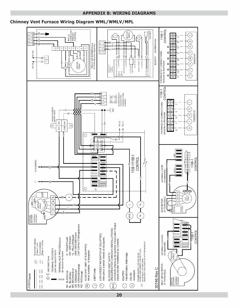
APPENDIX B: WIRING DIAGRAMS
Chimney Vent Furnace Wiring Diagram WML/WMLV/MPL
21
APPENDIX B: WIRING DIAGRAMS
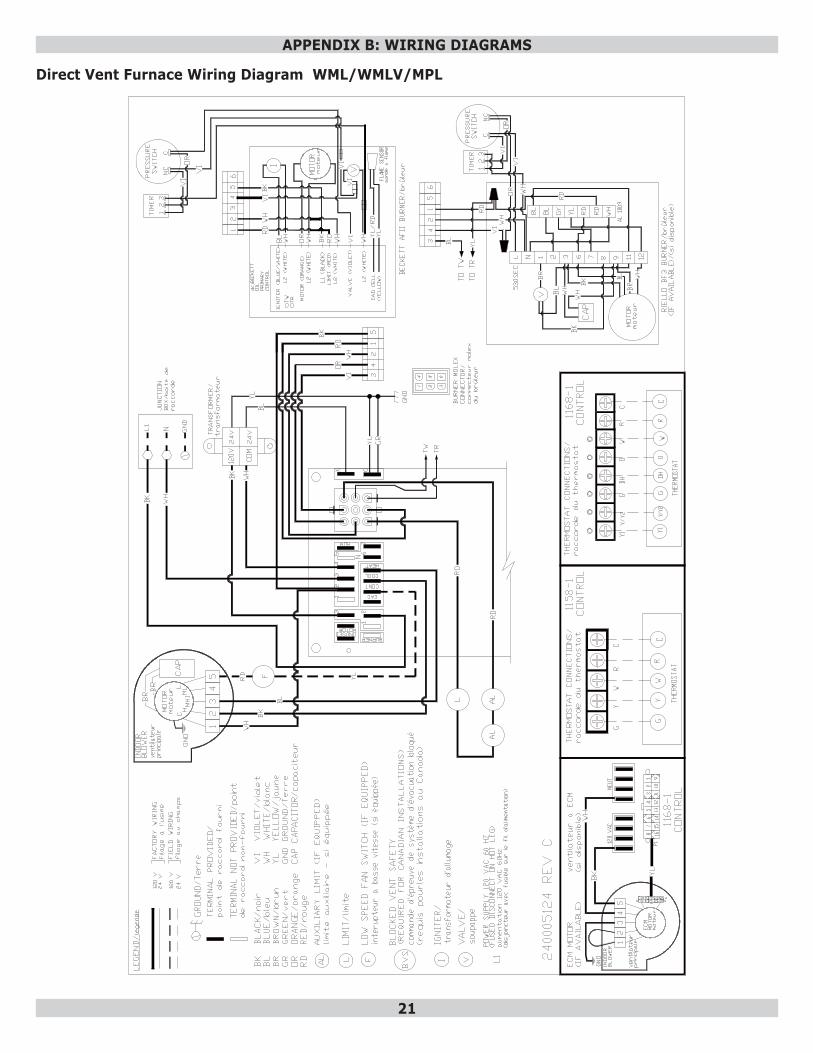
Direct Vent Furnace Wiring Diagram WML/WMLV/MPL
22
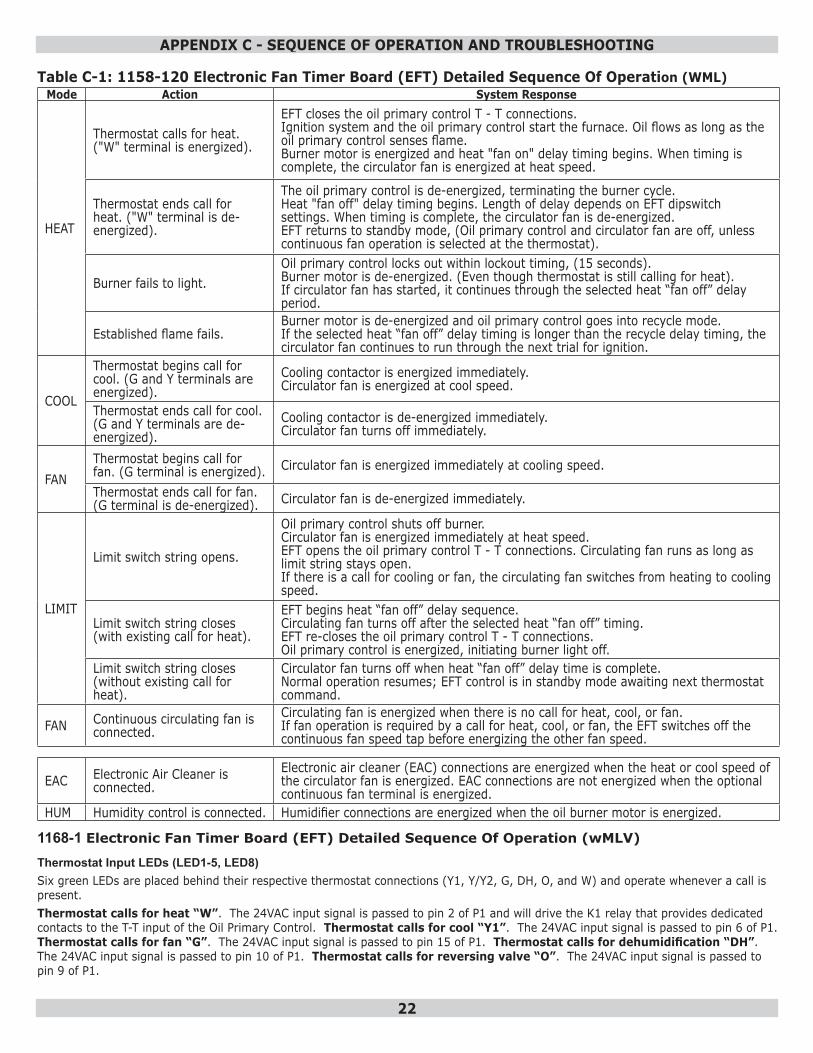
Table C-1: 1158-120 Electronic Fan Timer Board (EFT) Detailed Sequence Of Operation (WML)Mode Action System Response
HEAT
Thermostat calls for heat. ("W" terminal is energized).
EFT closes the oil primary control T - T connections.Ignition system and the oil primary control start the furnace. Oil flows as long as the oil primary control senses flame.Burner motor is energized and heat "fan on" delay timing begins. When timing is complete, the circulator fan is energized at heat speed.
Thermostat ends call for heat. ("W" terminal is de-energized).
The oil primary control is de-energized, terminating the burner cycle.Heat "fan off" delay timing begins. Length of delay depends on EFT dipswitch settings. When timing is complete, the circulator fan is de-energized.EFT returns to standby mode, (Oil primary control and circulator fan are off, unless continuous fan operation is selected at the thermostat).
Burner fails to light.Oil primary control locks out within lockout timing, (15 seconds).Burner motor is de-energized. (Even though thermostat is still calling for heat).If circulator fan has started, it continues through the selected heat “fan off” delay period.
Established flame fails.Burner motor is de-energized and oil primary control goes into recycle mode.If the selected heat “fan off” delay timing is longer than the recycle delay timing, the circulator fan continues to run through the next trial for ignition.
COOL
Thermostat begins call for cool. (G and Y terminals are energized).
Cooling contactor is energized immediately.Circulator fan is energized at cool speed.
Thermostat ends call for cool. (G and Y terminals are de-energized).
Cooling contactor is de-energized immediately.Circulator fan turns off immediately.
FANThermostat begins call for fan. (G terminal is energized). Circulator fan is energized immediately at cooling speed.
Thermostat ends call for fan. (G terminal is de-energized). Circulator fan is de-energized immediately.
LIMIT
Limit switch string opens.
Oil primary control shuts off burner.Circulator fan is energized immediately at heat speed.EFT opens the oil primary control T - T connections. Circulating fan runs as long as limit string stays open.If there is a call for cooling or fan, the circulating fan switches from heating to cooling speed.
Limit switch string closes (with existing call for heat).
EFT begins heat “fan off” delay sequence.Circulating fan turns off after the selected heat “fan off” timing.EFT re-closes the oil primary control T - T connections.Oil primary control is energized, initiating burner light off.
Limit switch string closes (without existing call for heat).
Circulator fan turns off when heat “fan off” delay time is complete.Normal operation resumes; EFT control is in standby mode awaiting next thermostat command.
FAN Continuous circulating fan is connected.
Circulating fan is energized when there is no call for heat, cool, or fan.If fan operation is required by a call for heat, cool, or fan, the EFT switches off the continuous fan speed tap before energizing the other fan speed.
EAC Electronic Air Cleaner is connected.
Electronic air cleaner (EAC) connections are energized when the heat or cool speed of the circulator fan is energized. EAC connections are not energized when the optional continuous fan terminal is energized.
HUM Humidity control is connected. Humidifier connections are energized when the oil burner motor is energized.
1168-1 Electronic Fan Timer Board (EFT) Detailed Sequence Of Operation (wMLV)
Thermostat Input LEDs (LED1-5, LED8)Six green LEDs are placed behind their respective thermostat connections (Y1, Y/Y2, G, DH, O, and W) and operate whenever a call is present.Thermostat calls for heat “W”. The 24VAC input signal is passed to pin 2 of P1 and will drive the K1 relay that provides dedicated contacts to the T-T input of the Oil Primary Control. Thermostat calls for cool “Y1”. The 24VAC input signal is passed to pin 6 of P1. Thermostat calls for fan “G”. The 24VAC input signal is passed to pin 15 of P1. Thermostat calls for dehumidification “DH”. The 24VAC input signal is passed to pin 10 of P1. Thermostat calls for reversing valve “O”. The 24VAC input signal is passed to pin 9 of P1.
APPENDIX C - SEQUENCE OF OPERATION AND TROUBLESHOOTING
23
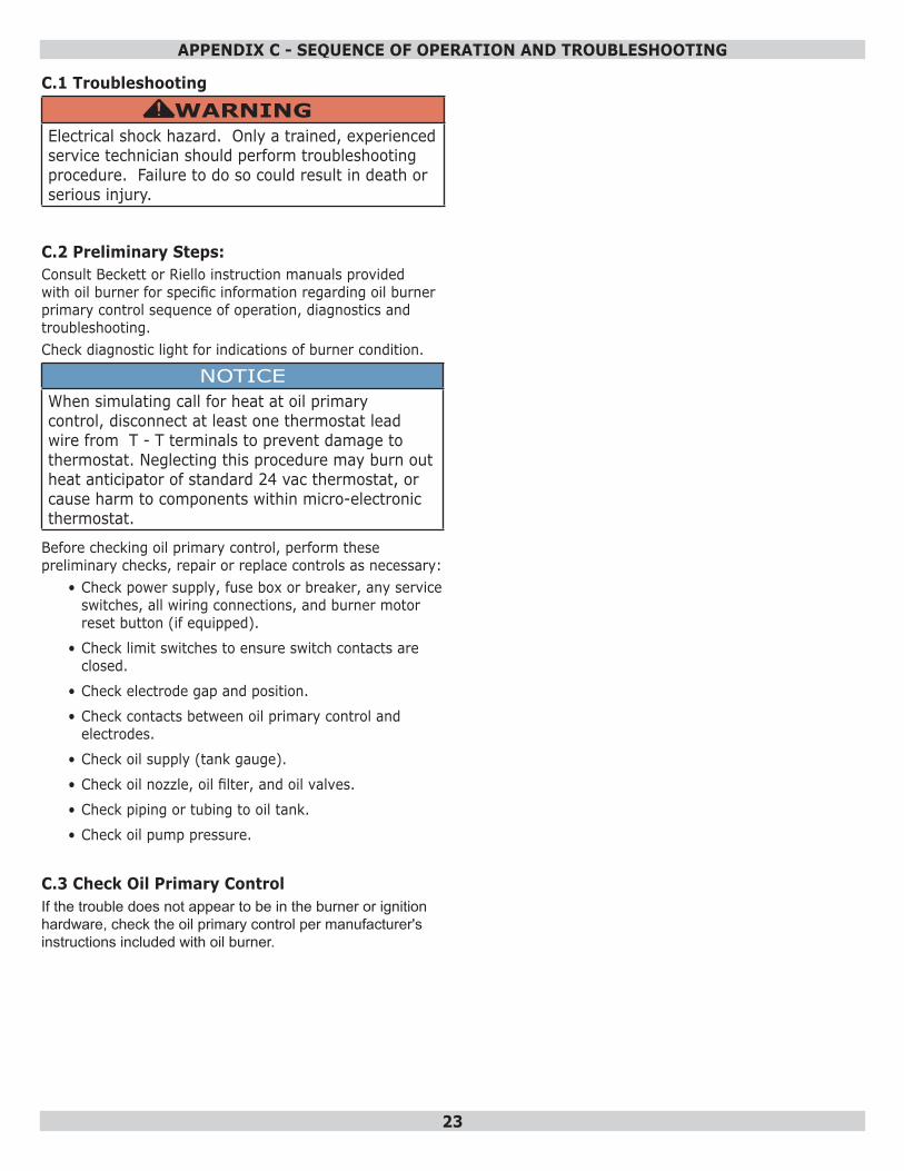
C.1 Troubleshooting
WARNINGElectrical shock hazard. Only a trained, experienced service technician should perform troubleshooting procedure. Failure to do so could result in death or serious injury.
!
C.2 Preliminary Steps:Consult Beckett or Riello instruction manuals provided with oil burner for specific information regarding oil burner primary control sequence of operation, diagnostics and troubleshooting.Check diagnostic light for indications of burner condition.
NOTICEWhen simulating call for heat at oil primary control, disconnect at least one thermostat lead wire from T - T terminals to prevent damage to thermostat. Neglecting this procedure may burn out heat anticipator of standard 24 vac thermostat, or cause harm to components within micro-electronic thermostat.
Before checking oil primary control, perform these preliminary checks, repair or replace controls as necessary:
• Check power supply, fuse box or breaker, any service switches, all wiring connections, and burner motor reset button (if equipped).
• Check limit switches to ensure switch contacts are closed.
• Check electrode gap and position.
• Check contacts between oil primary control and electrodes.
• Check oil supply (tank gauge).
• Check oil nozzle, oil filter, and oil valves.
• Check piping or tubing to oil tank.
• Check oil pump pressure.
C.3 Check Oil Primary ControlIf the trouble does not appear to be in the burner or ignition hardware, check the oil primary control per manufacturer's instructions included with oil burner.
APPENDIX C - SEQUENCE OF OPERATION AND TROUBLESHOOTING
24
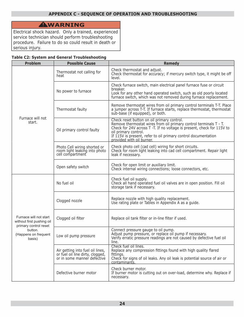
Table C2: System and General TroubleshootingProblem Possible Cause Remedy
Furnace will not start.
Thermostat not calling for heat
Check thermostat and adjust.Check thermostat for accuracy; if mercury switch type, it might be off level.
No power to furnaceCheck furnace switch, main electrical panel furnace fuse or circuit breaker. Look for any other hand operated switch, such as old poorly located furnace switch, which was not removed during furnace replacement.
Thermostat faultyRemove thermostat wires from oil primary control terminals T-T. Place a jumper across T-T. If furnace starts, replace thermostat, thermostat sub-base (if equipped), or both.
Oil primary control faulty
Check reset button on oil primary control. Remove thermostat wires from oil primary control terminals T - T. Check for 24V across T -T. If no voltage is present, check for 115V to oil primary control. If 115V is present, refer to oil primary control documentation provided with oil burner.
Photo Cell wiring shorted or room light leaking into photo cell compartment
Check photo cell (cad cell) wiring for short circuits. Check for room light leaking into cad cell compartment. Repair light leak if necessary.
Open safety switch Check for open limit or auxiliary limit. Check internal wiring connections; loose connectors, etc.
Furnace will not start without first pushing oil primary control reset
button.(Happens on frequent
basis)
No fuel oilCheck fuel oil supply. Check all hand operated fuel oil valves are in open position. Fill oil storage tank if necessary.
Clogged nozzle Replace nozzle with high quality replacement. Use rating plate or Tables in Appendix A as a guide.
Clogged oil filter Replace oil tank filter or in-line filter if used.
Low oil pump pressureConnect pressure gauge to oil pump. Adjust pump pressure, or replace oil pump if necessary. Verify erratic pressure readings are not caused by defective fuel oil line.
Air getting into fuel oil lines, or fuel oil line dirty, clogged, or in some manner defective
Check fuel oil lines. Replace any compression fittings found with high quality flared fittings. Check for signs of oil leaks. Any oil leak is potential source of air or contaminants.
Defective burner motorCheck burner motor.If burner motor is cutting out on over-load, determine why. Replace if necessary.
WARNINGElectrical shock hazard. Only a trained, experienced service technician should perform troubleshooting procedure. Failure to do so could result in death or serious injury.
!
APPENDIX C - SEQUENCE OF OPERATION AND TROUBLESHOOTING
25
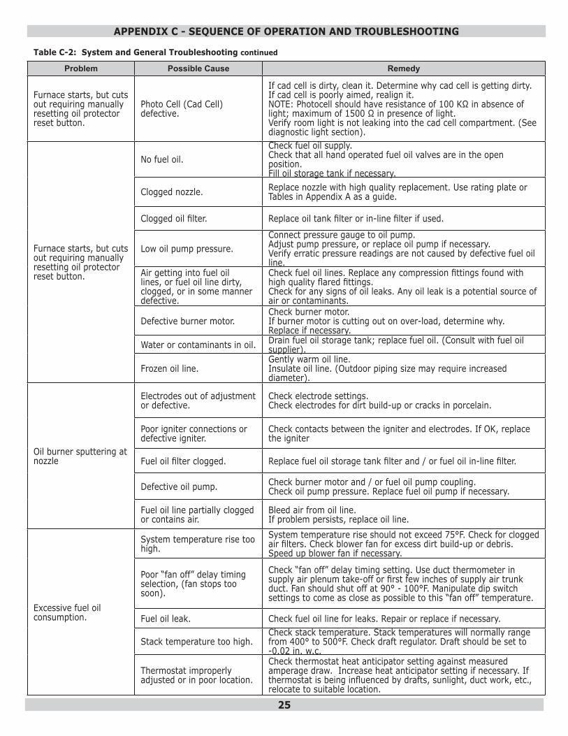
Table C-2: System and General Troubleshooting continued
Problem Possible Cause Remedy
Furnace starts, but cuts out requiring manually resetting oil protector reset button.
Photo Cell (Cad Cell) defective.
If cad cell is dirty, clean it. Determine why cad cell is getting dirty. If cad cell is poorly aimed, realign it. NOTE: Photocell should have resistance of 100 KΩ in absence of light; maximum of 1500 Ω in presence of light. Verify room light is not leaking into the cad cell compartment. (See diagnostic light section).
Furnace starts, but cuts out requiring manually resetting oil protector reset button.
No fuel oil.Check fuel oil supply. Check that all hand operated fuel oil valves are in the open position. Fill oil storage tank if necessary.
Clogged nozzle. Replace nozzle with high quality replacement. Use rating plate or Tables in Appendix A as a guide.
Clogged oil filter. Replace oil tank filter or in-line filter if used.
Low oil pump pressure.Connect pressure gauge to oil pump. Adjust pump pressure, or replace oil pump if necessary. Verify erratic pressure readings are not caused by defective fuel oil line.
Air getting into fuel oil lines, or fuel oil line dirty, clogged, or in some manner defective.
Check fuel oil lines. Replace any compression fittings found with high quality flared fittings. Check for any signs of oil leaks. Any oil leak is a potential source of air or contaminants.
Defective burner motor.Check burner motor. If burner motor is cutting out on over-load, determine why. Replace if necessary.
Water or contaminants in oil. Drain fuel oil storage tank; replace fuel oil. (Consult with fuel oil supplier).
Frozen oil line.Gently warm oil line. Insulate oil line. (Outdoor piping size may require increased diameter).
Oil burner sputtering at nozzle
Electrodes out of adjustment or defective.
Check electrode settings. Check electrodes for dirt build-up or cracks in porcelain.
Poor igniter connections or defective igniter.
Check contacts between the igniter and electrodes. If OK, replace the igniter
Fuel oil filter clogged. Replace fuel oil storage tank filter and / or fuel oil in-line filter.
Defective oil pump. Check burner motor and / or fuel oil pump coupling.Check oil pump pressure. Replace fuel oil pump if necessary.
Fuel oil line partially clogged or contains air.
Bleed air from oil line. If problem persists, replace oil line.
Excessive fuel oil consumption.
System temperature rise too high.
System temperature rise should not exceed 75°F. Check for clogged air filters. Check blower fan for excess dirt build-up or debris. Speed up blower fan if necessary.
Poor “fan off” delay timing selection, (fan stops too soon).
Check “fan off” delay timing setting. Use duct thermometer in supply air plenum take-off or first few inches of supply air trunk duct. Fan should shut off at 90° - 100°F. Manipulate dip switch settings to come as close as possible to this “fan off” temperature.
Fuel oil leak. Check fuel oil line for leaks. Repair or replace if necessary.
Stack temperature too high.Check stack temperature. Stack temperatures will normally range from 400° to 500°F. Check draft regulator. Draft should be set to -0.02 in. w.c.
Thermostat improperly adjusted or in poor location.
Check thermostat heat anticipator setting against measured amperage draw. Increase heat anticipator setting if necessary. If thermostat is being influenced by drafts, sunlight, duct work, etc., relocate to suitable location.
APPENDIX C - SEQUENCE OF OPERATION AND TROUBLESHOOTING
26
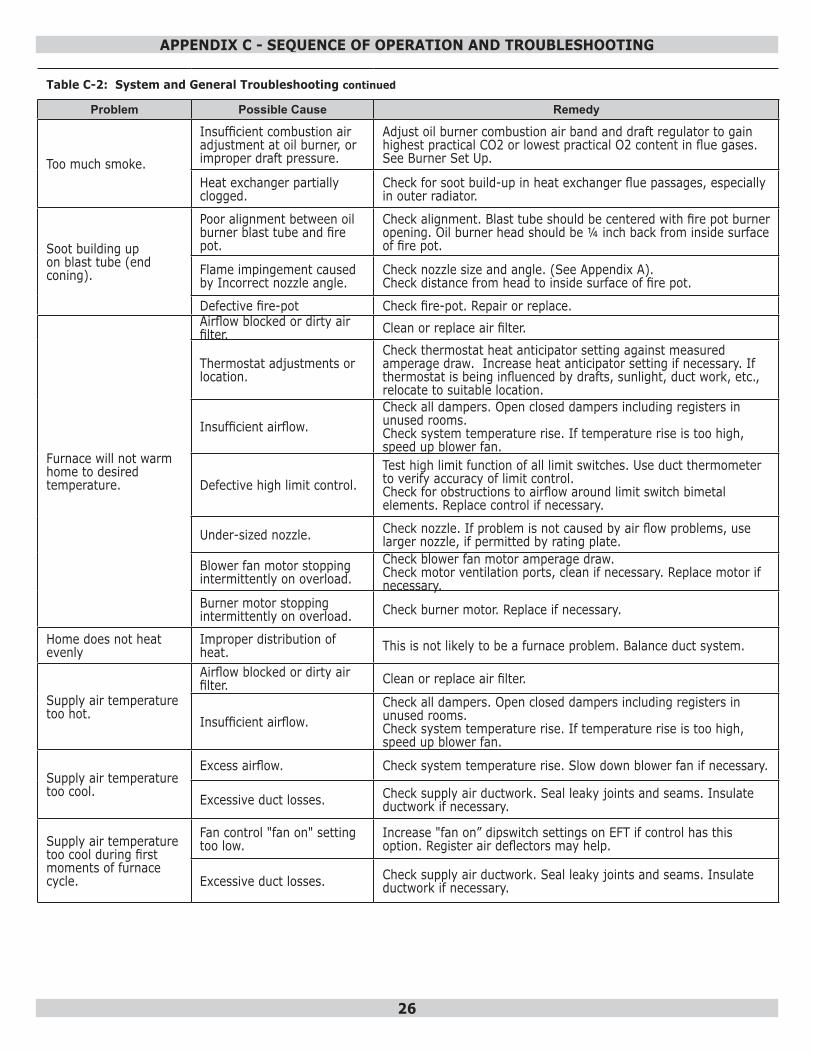
Table C-2: System and General Troubleshooting continued
Problem Possible Cause Remedy
Too much smoke.
Insufficient combustion air adjustment at oil burner, or improper draft pressure.
Adjust oil burner combustion air band and draft regulator to gain highest practical CO2 or lowest practical O2 content in flue gases. See Burner Set Up.
Heat exchanger partially clogged.
Check for soot build-up in heat exchanger flue passages, especially in outer radiator.
Soot building up on blast tube (end coning).
Poor alignment between oil burner blast tube and fire pot.
Check alignment. Blast tube should be centered with fire pot burner opening. Oil burner head should be ¼ inch back from inside surface of fire pot.
Flame impingement caused by Incorrect nozzle angle.
Check nozzle size and angle. (See Appendix A). Check distance from head to inside surface of fire pot.
Defective fire-pot Check fire-pot. Repair or replace.
Furnace will not warm home to desired temperature.
Airflow blocked or dirty air filter. Clean or replace air filter.
Thermostat adjustments or location.
Check thermostat heat anticipator setting against measured amperage draw. Increase heat anticipator setting if necessary. If thermostat is being influenced by drafts, sunlight, duct work, etc., relocate to suitable location.
Insufficient airflow.Check all dampers. Open closed dampers including registers in unused rooms. Check system temperature rise. If temperature rise is too high, speed up blower fan.
Defective high limit control.Test high limit function of all limit switches. Use duct thermometer to verify accuracy of limit control. Check for obstructions to airflow around limit switch bimetal elements. Replace control if necessary.
Under-sized nozzle. Check nozzle. If problem is not caused by air flow problems, use larger nozzle, if permitted by rating plate.
Blower fan motor stopping intermittently on overload.
Check blower fan motor amperage draw. Check motor ventilation ports, clean if necessary. Replace motor if necessary.
Burner motor stopping intermittently on overload. Check burner motor. Replace if necessary.
Home does not heat evenly
Improper distribution of heat. This is not likely to be a furnace problem. Balance duct system.
Supply air temperature too hot.
Airflow blocked or dirty air filter. Clean or replace air filter.
Insufficient airflow.Check all dampers. Open closed dampers including registers in unused rooms. Check system temperature rise. If temperature rise is too high, speed up blower fan.
Supply air temperature too cool.
Excess airflow. Check system temperature rise. Slow down blower fan if necessary.
Excessive duct losses. Check supply air ductwork. Seal leaky joints and seams. Insulate ductwork if necessary.
Supply air temperature too cool during first moments of furnace cycle.
Fan control "fan on" setting too low.
Increase "fan on” dipswitch settings on EFT if control has this option. Register air deflectors may help.
Excessive duct losses. Check supply air ductwork. Seal leaky joints and seams. Insulate ductwork if necessary.
APPENDIX C - SEQUENCE OF OPERATION AND TROUBLESHOOTING
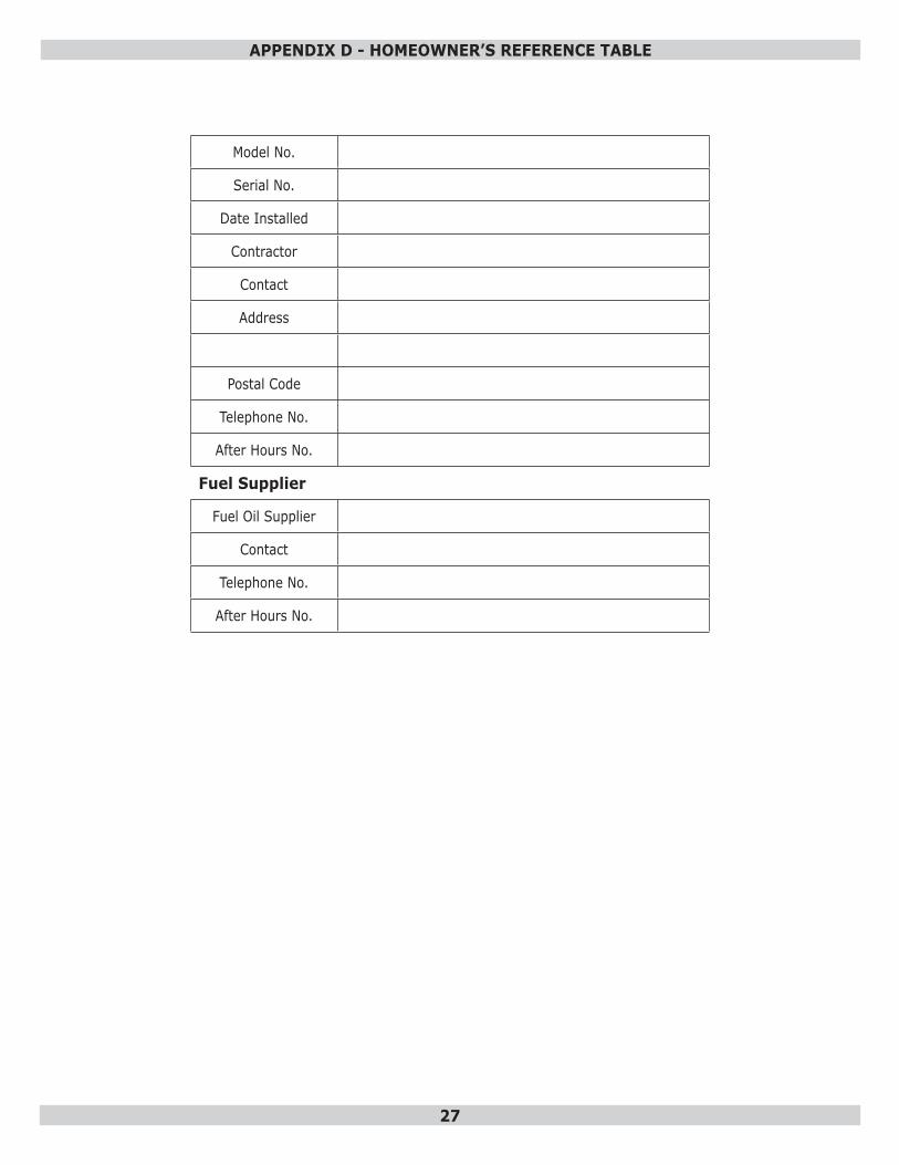
27
Model No.
Serial No.
Date Installed
Contractor
Contact
Address
Postal Code
Telephone No.
After Hours No.
Fuel Supplier
Fuel Oil Supplier
Contact
Telephone No.
After Hours No.
APPENDIX D - HOMEOWNER’S REFERENCE TABLE
28
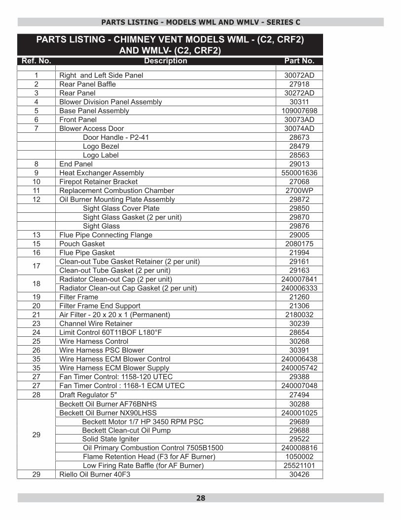
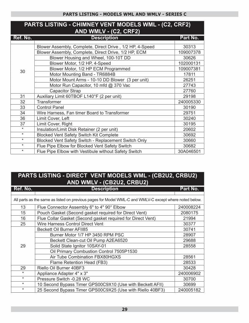
PARTS LISTING - MODELS WML AND WMLV - SERIES C
PARTS LISTING - CHIMNEY VENT MODELS WML - (C2, CRF2) AND WMLV- (C2, CRF2)
Ref. No. Description Part No.
1 Right and Left Side Panel 30072AD2 Rear Panel Baffle 279183 Rear Panel 30272AD4 Blower Division Panel Assembly 303115 Base Panel Assembly 1090076986 Front Panel 30073AD7 Blower Access Door 30074AD
Door Handle - P2-41 28673Logo Bezel 28479Logo Label 28563
8 End Panel 290139 Heat Exchanger Assembly 550001636
10 Firepot Retainer Bracket 2706811 Replacement Combustion Chamber 2700WP12 Oil Burner Mounting Plate Assembly 29872
Sight Glass Cover Plate 29850Sight Glass Gasket (2 per unit) 29870Sight Glass 29876
13 Flue Pipe Connecting Flange 2900515 Pouch Gasket 208017516 Flue Pipe Gasket 21994
17 Clean-out Tube Gasket Retainer (2 per unit) 29161Clean-out Tube Gasket (2 per unit) 29163
18 Radiator Clean-out Cap (2 per unit) 240007841Radiator Clean-out Cap Gasket (2 per unit) 240006333
19 Filter Frame 2126020 Filter Frame End Support 2130621 Air Filter - 20 x 20 x 1 (Permanent) 218003223 Channel Wire Retainer 3023924 Limit Control 60T11BOF L180°F 2865425 Wire Harness Control 3026826 Wire Harness PSC Blower 3039135 Wire Harness ECM Blower Control 24000643835 Wire Harness ECM Blower Supply 24000574227 Fan Timer Control: 1158-120 UTEC 2938827 Fan Timer Control : 1168-1 ECM UTEC 24000704828 Draft Regulator 5" 27494
29
Beckett Oil Burner AF76BNHS 30288Beckett Oil Burner NX90LHSS 240001025
Beckett Motor 1/7 HP 3450 RPM PSC 29689Beckett Clean-cut Oil Pump 29688Solid State Igniter 29522Oil Primary Combustion Control 7505B1500 240008816Flame Retention Head (F3 for AF Burner) 1050002Low Firing Rate Baffle (for AF Burner) 25521101
29 Riello Oil Burner 40F3 30426
29
PARTS LISTING - CHIMNEY VENT MODELS WML - (C2, CRF2) AND WMLV - (C2, CRF2)
Ref. No. Description Part No.
30
Blower Assembly, Complete, Direct Drive , 1/2 HP, 4-Speed 30313Blower Assembly, Complete, Direct Drive, 1/2 HP, ECM 109007378
Blower Housing and Wheel, 100-10T DD 30626Blower Motor, 1/2 HP, 4-Speed 102000131Blower Motor, 1/2 HP ECM Programmed 109007381Motor Mounting Band - TR6884B 17811Motor Mount Arms - 10-10 DD Blower (3 per unit) 26251Motor Run Capacitor, 10 mfd @ 370 Vac 27743Capacitor Strap 27760
31 Auxiliary Limit 60TBOF L140°F (2 per unit) 2919832 Transformer 24000533033 Control Panel 3019034 Wire Harness, Fan timer Board to Transformer 2975136 Limit Cover, Left 3024037 Limit Cover, Right 30195* Insulation/Limit Disk Retainer (2 per unit) 20602* Blocked Vent Safety Switch Kit Complete 30692* Blocked Vent Safety Switch - Replacement Switch Only 30660* Flue Pipe Elbow for Blocked Vent Safety Switch 30682* Flue Pipe Elbow with Vestibule without Safety Switch 30A046501
PARTS LISTING - MODELS WML AND WMLV - SERIES C
PARTS LISTING - DIRECT VENT MODELS WML - (CB2U2, CRBU2) AND WMLV - (CB2U2, CRBU2)
Ref. No. Description Part No.
All parts as the same as listed on previous pages for Model WML-C and WMLV-C except where noted below.
13 Flue Connector Assembly 6" to 4" 90° Elbow 24000822415 Pouch Gasket (Second gasket required for Direct Vent) 208017516 Flue Collar Gasket (Second gasket required for Direct Vent) 2199425 Wire Harness Control Direct Vent 30377
29
Beckett Oil Burner AFII85 30741Burner Motor 1/7 HP 3450 RPM PSC 28907Beckett Clean-cut Oil Pump A2EA6520 29688Solid State Ignitor 10SAY-01 28558Oil Primary Combustion Control 7505P1530Air Tube Combination FBX80HGXS 28561Flame Retention Head (FB3) 28533
29 Riello Oil Burner 40BF3 30428* Appliance Adapter 4" x 3" 240006902* Pressure Switch -0.28 WC 30700* 10 Second Bypass Timer GPS00C9X10 (Use with Beckett AFII) 30699* 25 Second Bypass Timer GPS00C9X25 (Use with Riello 40BF3) 240005182
30
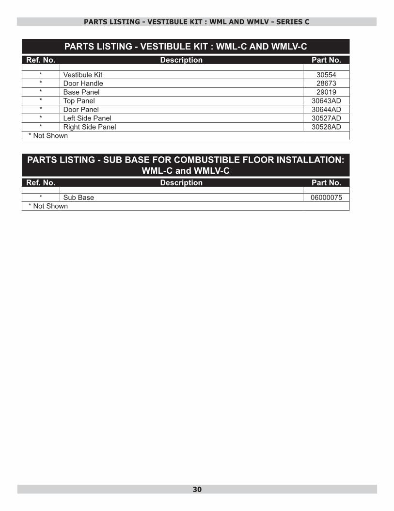
PARTS LISTING - VESTIBULE KIT : WML-C AND WMLV-CRef. No. Description Part No.
* Vestibule Kit 30554* Door Handle 28673* Base Panel 29019* Top Panel 30643AD* Door Panel 30644AD* Left Side Panel 30527AD* Right Side Panel 30528AD
* Not Shown
PARTS LISTING - VESTIBULE KIT : WML AND WMLV - SERIES C
PARTS LISTING - SUB BASE FOR COMBUSTIBLE FLOOR INSTALLATION: WML-C and WMLV-C
Ref. No. Description Part No.
* Sub Base 06000075* Not Shown
31
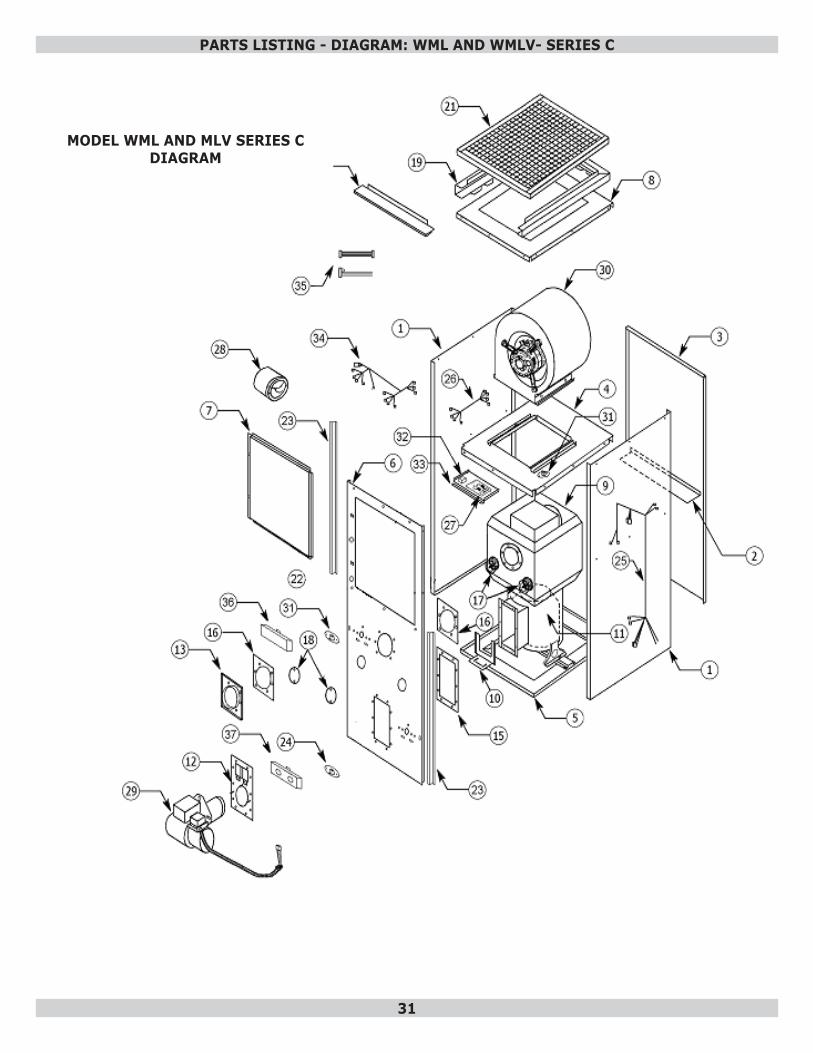
PARTS LISTING - DIAGRAM: WML AND WMLV- SERIES C
MODEL WML AND MLV SERIES C DIAGRAM
32
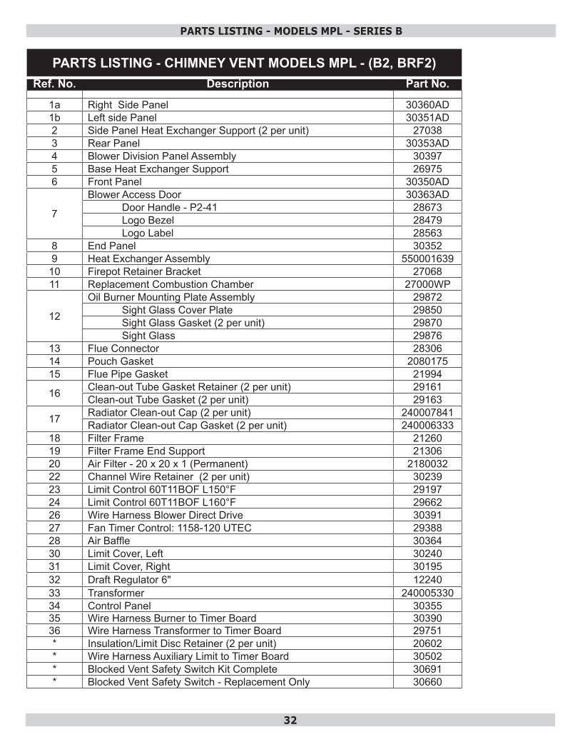
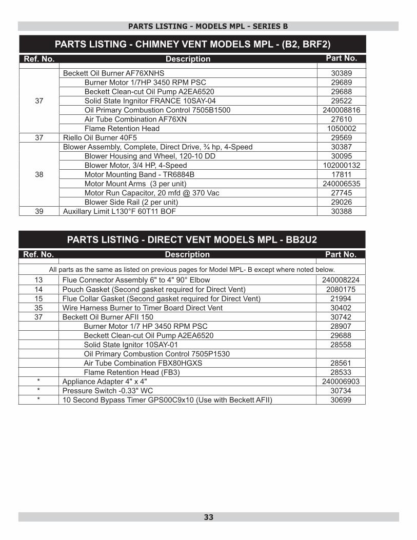
PARTS LISTING - CHIMNEY VENT MODELS MPL - (B2, BRF2)Ref. No. Description Part No.
1a Right Side Panel 30360AD1b Left side Panel 30351AD2 Side Panel Heat Exchanger Support (2 per unit) 270383 Rear Panel 30353AD4 Blower Division Panel Assembly 303975 Base Heat Exchanger Support 269756 Front Panel 30350AD
7
Blower Access Door 30363ADDoor Handle - P2-41 28673Logo Bezel 28479Logo Label 28563
8 End Panel 303529 Heat Exchanger Assembly 550001639
10 Firepot Retainer Bracket 2706811 Replacement Combustion Chamber 27000WP
12
Oil Burner Mounting Plate Assembly 29872Sight Glass Cover Plate 29850Sight Glass Gasket (2 per unit) 29870Sight Glass 29876
13 Flue Connector 2830614 Pouch Gasket 208017515 Flue Pipe Gasket 21994
16 Clean-out Tube Gasket Retainer (2 per unit) 29161Clean-out Tube Gasket (2 per unit) 29163
17 Radiator Clean-out Cap (2 per unit) 240007841Radiator Clean-out Cap Gasket (2 per unit) 240006333
18 Filter Frame 2126019 Filter Frame End Support 2130620 Air Filter - 20 x 20 x 1 (Permanent) 218003222 Channel Wire Retainer (2 per unit) 3023923 Limit Control 60T11BOF L150°F 2919724 Limit Control 60T11BOF L160°F 2966226 Wire Harness Blower Direct Drive 3039127 Fan Timer Control: 1158-120 UTEC 2938828 Air Baffle 3036430 Limit Cover, Left 3024031 Limit Cover, Right 3019532 Draft Regulator 6" 1224033 Transformer 24000533034 Control Panel 3035535 Wire Harness Burner to Timer Board 3039036 Wire Harness Transformer to Timer Board 29751* Insulation/Limit Disc Retainer (2 per unit) 20602* Wire Harness Auxiliary Limit to Timer Board 30502* Blocked Vent Safety Switch Kit Complete 30691* Blocked Vent Safety Switch - Replacement Only 30660
PARTS LISTING - MODELS MPL - SERIES B
33
PARTS LISTING - CHIMNEY VENT MODELS MPL - (B2, BRF2)Ref. No. Description Part No.
37
Beckett Oil Burner AF76XNHS 30389Burner Motor 1/7HP 3450 RPM PSC 29689Beckett Clean-cut Oil Pump A2EA6520 29688Solid State Ingnitor FRANCE 10SAY-04 29522Oil Primary Combustion Control 7505B1500 240008816Air Tube Combination AF76XN 27610Flame Retention Head 1050002
37 Riello Oil Burner 40F5 29569
38
Blower Assembly, Complete, Direct Drive, ¾ hp, 4-Speed 30387Blower Housing and Wheel, 120-10 DD 30095Blower Motor, 3/4 HP, 4-Speed 102000132Motor Mounting Band - TR6884B 17811Motor Mount Arms (3 per unit) 240006535Motor Run Capacitor, 20 mfd @ 370 Vac 27745Blower Side Rail (2 per unit) 29026
39 Auxillary Limit L130°F 60T11 BOF 30388
PARTS LISTING - MODELS MPL - SERIES B
PARTS LISTING - DIRECT VENT MODELS MPL - BB2U2Ref. No. Description Part No.
All parts as the same as listed on previous pages for Model MPL- B except where noted below.13 Flue Connector Assembly 6" to 4" 90° Elbow 24000822414 Pouch Gasket (Second gasket required for Direct Vent) 208017515 Flue Collar Gasket (Second gasket required for Direct Vent) 2199435 Wire Harness Burner to Timer Board Direct Vent 3040237 Beckett Oil Burner AFII 150 30742
Burner Motor 1/7 HP 3450 RPM PSC 28907Beckett Clean-cut Oil Pump A2EA6520 29688Solid State Ignitor 10SAY-01 28558Oil Primary Combustion Control 7505P1530Air Tube Combination FBX80HGXS 28561Flame Retention Head (FB3) 28533
* Appliance Adapter 4" x 4" 240006903* Pressure Switch -0.33" WC 30734* 10 Second Bypass Timer GPS00C9x10 (Use with Beckett AFII) 30699
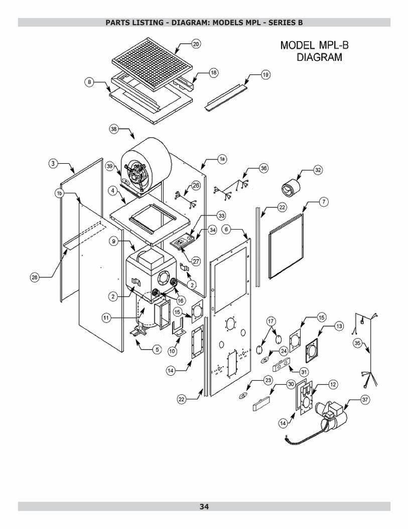
34
PARTS LISTING - DIAGRAM: MODELS MPL - SERIES B

35
ECR International 2210 Dwyer Avenue, Utica NY 13501web site: www.ecrinternational.com