Embed Size (px)
Citation preview
1 of 28 Rev LFebruary 15, 2005
FM Series BMS Address Map
=Controller F/W Versions 6.3.0 and later
=Controller F/W Versions 6.8.0 and later
MAIN MODULE/SYSTEM DATAAddress Length Bit Description Data Range Units Functions R/W Scaling(decimal) (in words) Position Supported
Miscellaneous0 15 N/A Manufacturer's Name ascii string N/A 3,4 R N/A
15 15 N/A Product Name ascii string N/A 3,4/16 R/W N/A30 15 N/A Product Location ascii string N/A 3,4/16 R/W N/A45 15 N/A Contact ascii string N/A 3,4/16 R/W N/A60 10 N/A Model Number ascii string N/A 3,4 R N/A70 6 N/A Date of Manufacture ascii string
mm/dd/yyyyN/A 3,4 R N/A
76 10 N/A Serial Number ascii string N/A 3,4 R N/A86 8 N/A Firmware Revision ascii string N/A 3,4 R N/A94 4 N/A Hardware Revision ascii string N/A 3,4 R N/A98 6 N/A System Date-Time Record 3,4/16 R/W
Offset 0 1 N/A System Time Hour 0 to 23 Hours 1Offset 1 1 N/A System Time Minutes 0 to 59 Minutes 1Offset 2 1 N/A System Time Seconds 0 to 59 Seconds 1Offset 3 1 N/A System Date Month 0 to 12 Months 1Offset 4 1 N/A System Date Day 1 to 31 Days 1Offset 5 1 N/A System Date Year 0 to 9999 Years 1
104 1 N/A System On 0 = Off1 = On
N/A 3,4 R 1
105 1 N/A Startup Delay 0 to 999 Seconds 3,4/16 R/W 1106 1 N/A Mode Delay 0 to 999 Seconds 3,4/16 R/W 1107 1 N/A Humidity Control Method 0 = Relative Humidity
1 = Dew PointN/A 3,4/16 R/W 1
108 1 N/A Blower Speed 200 to 600 .1 Hz 3,4/16 R/W 1109 1 N/A Primary Sensors 0 = Return Sensors
1 = Remote SensorsN/A 3,4/16 R/W 1
110 1 N/A Remote Sensor Reading 0 = Average Temperature1 = Maximum Temperature
N/A 3,4/16 R/W 1
111 1 N/A Comm Loss Shutdown Delay 0 to 24, -1 = no shutdown
Hours 3,4/16 R/W 1
112 1 N/A Cooling Essential 0 = Essential1 = Non-essential
N/A 3,4/16 R/W 1
113 1 N/A Re-Heat Essential 0 = Essential1 = Non-essential
N/A 3,4/16 R/W 1
114 1 N/A Humidification Essential 0 = Essential1 = Non-essential
N/A 3,4/16 R/W 1
115 1 N/A De-Humidification Essential 0 = Essential1 = Non-essential
N/A 3,4/16 R/W 1
116 1 N/A Fast Startup Enable 0 = Disabled1 = Enabled
N/A 3,4/16 R/W 1
117 1 N/A Current Humidity Control Method
0 = Relative Humidity1 = Dew Point
N/A 3,4 R 1
118 119 Reserved 3,4 RModule Configuration
237 1 N/A Output Capacity 1 = 152 = 353 = 404 = 505 = 80
kW 3,4/16 R/W 1
238 1 N/A Coil Configuration 0 = DX1 = Econ2 = Multi-Cool3 = Liquid Cool
N/A 3,4/16 R/W 1
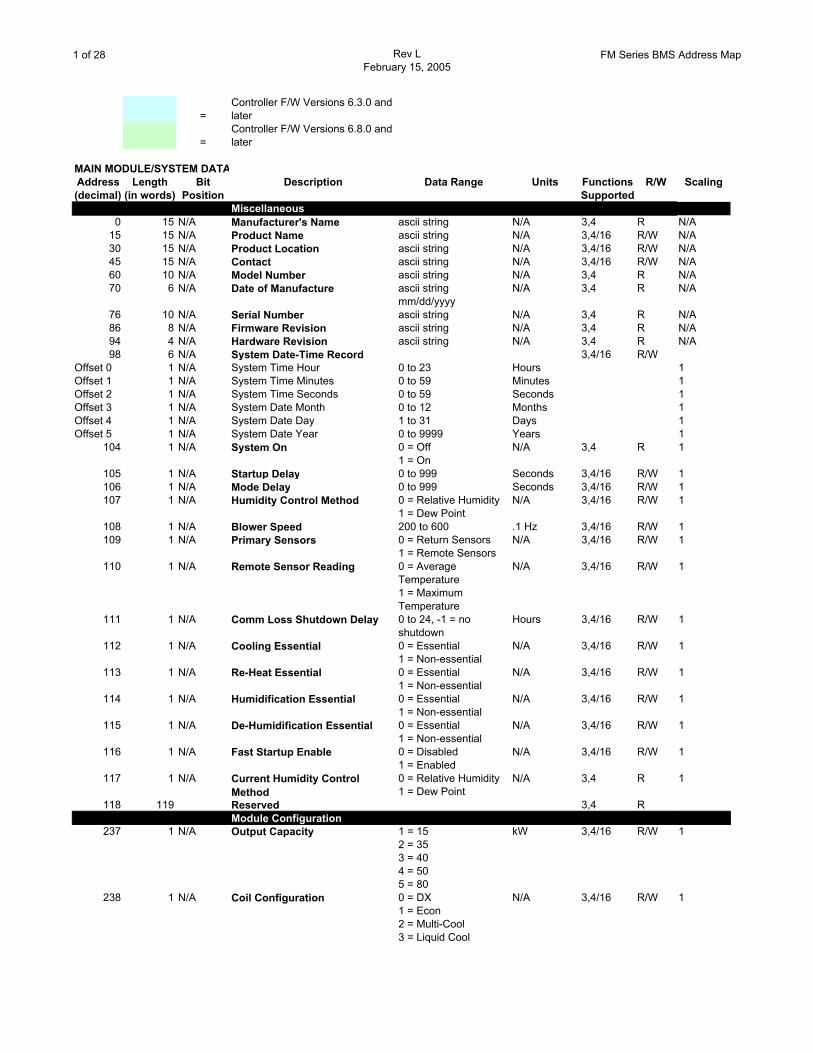
2 of 28 Rev LFebruary 15, 2005
FM Series BMS Address Map
Address Length Bit Description Data Range Units Functions R/W Scaling(decimal) (in words) Position Supported
239 1 N/A Air Flow Direction 0 = Up1 = Down2 = Horizontal
N/A 3,4/16 R/W 1
240 1 N/A Heat of Rejection Method 0 = Air1 = Water2 = Glycol
N/A 3,4/16 R/W 1
241 1 N/A Heater Type 0 = None1 = Electric SCR2 = Steam3 = Hot Water On-Off4 = Hot Gas Reheat5 = Hot Gas & Electric6 = Hot Water Proportional
N/A 3,4/16 R/W 1
242 1 N/A Capacity Control 0 = Tandem1 = Hot Gas Bypass
N/A 3,4 R 1
243 1 N/A Humidifier Type 0 = None1 = Steam Electrode2 = Live Steam
N/A 3,4/16 R/W 1
244 1 N/A Water Regulation Actuator 0 = None2 = Floating Control
N/A 3,4/16 R/W 1
245 1 N/A Pre-Cool/MultiCool Actuator 0 = None1 = Spring Analog2 = Floating Control
N/A 3,4/16 R/W 1
246 1 N/A Mains Voltage 0 = 208/3/601 = 230/3/602 = 380/3/603 = 460/3/604 = 480/3/605 = 575/3/606 = 200/3/507 = 380/3/508 = 415/3/50
N/A 3,4/16 R/W 1
247 1 N/A Smoke Alarm 0 = Not Present1 = Present
N/A 3,4/16 R/W 1
248 1 N/A Water Alarm 0 = Not Present1 = Present
N/A 3,4/16 R/W 1
249 1 N/A Fire Alarm 0 = Not Present1 = Present
N/A 3,4/16 R/W 1
250 1 N/A Number of PCIOMs 0 to 4 N/A 3,4/16 R/W 1251 1 N/A Flow Switch 0 = None
1 = DX/Econ2 = Multi-Cool/Chilled Water
N/A 3,4/16 R/W 1
252 1 N/A Hot Water Actuator 0 = None1 = Spring Analog2 = Floating Control
N/A 3,4/16 R/W 1
253 1 N/A Water Regulation Valve Type 0 = 2 way1 = 3 way
N/A 3,4/16 R/W 1
254 1 N/A Econ/Multi-Cool Valve Type 0 = 2 way1 = 3 way
N/A 3,4/16 R/W 1
255 1 Reserved 0 N/A 3,4/16 R/W 1256 1 N/A Condensate Pump 0 = Not Present
1 = PresentN/A 3,4/16 R/W 1
257 1 N/A Air Filter 0 = Standard1 = High Efficiency
N/A 3,4/16 R/W 1
258 1 N/A Number of Modules 1 to 3 Modules 3,4/16 R/W 1259 1 N/A Default Primary Sensors 0 = Return Sensors
1 = Remote SensorsN/A 3,4/16 R/W 1
260 1 N/A Electric Heater Type 0 = 10kW1 = 15kW
N/A 3,4/16 R/W 1
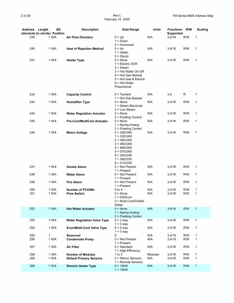
3 of 28 Rev LFebruary 15, 2005
FM Series BMS Address Map
Address Length Bit Description Data Range Units Functions R/W Scaling(decimal) (in words) Position Supported
261 1 N/A Nominal Coil DP 0.1 to 1.0 in. W.C. 3,4/16 R/W S(7)262 1 N/A UPS Voltage 0 = Not
Configured(Read Only)1 = None2 = 2003 = 2084 = 2305 = 3806 = 4007 = 4158 = 4609 = 48010 = 575
N/A 3,4/16 R/W 1
263 1 N/A Refrigerant Type 0 = R221 = R407C
N/A 3,4/16 R/W 1
264 59 Reserved 3,4 RCooling
323 1 N/A Enable 0 = Disabled1 = Enabled
N/A 3,4/16 R/W 1
324 2 N/A Set Point 15.5625 to 32.21875 °C 3,4/16 R/W S(5)326 2 N/A Deadband 0.28125 to 5.5625 °C 3,4/16 R/W S(5)328 2 N/A Liquid Cooling Threshold 4.4375 to 32.21875 °C 3,4/16 R/W S(5)330 2 N/A Liquid Cooling Deadband 0.5625 to 5.5625 °C 3,4/16 R/W S(5)332 1 N/A Interstage Delay 60 to 999 Seconds 3,4/16 R/W 1333 1 N/A Compressor Min. On Time 120 to 300 Seconds 3,4/16 R/W 1334 1 N/A Compressor Min. Off Time 120 to 300 Seconds 3,4/16 R/W 1335 1 N/A Water Reg. Valve Close Delay 0 to 1200 Seconds 3,4/16 R/W 1
336 1 N/A Cool Ant. Valve Close Delay 45 to 60 Minutes 3,4/16 R/W 1337 1 N/A Compressor Alloc. Timeout 0 to 999 Hours 3,4/16 R/W 1
Re-Heating338 1 N/A Enable 0 = Disabled
1 = EnabledN/A 3,4/16 R/W 1
339 2 N/A Set Point 15.5625 to 32.21875 °C 3,4/16 R/W S(5)341 2 N/A Deadband 0.28125 to 5.5625 °C 3,4/16 R/W S(5)
Humidification343 1 N/A Enable 0 = Disabled
1 = EnabledN/A 3,4/16 R/W 1
344 2 N/A Set Point 30.0 to 80.0 %RH 3,4/16 R/W S(5)346 2 N/A Deadband 0.5 to 10.0 %RH 3,4/16 R/W S(5)348 1 N/A Function Select 0 = Off
1 = Auto2 = Drain
N/A 3,4/16 R/W 1
Dehumidification349 1 N/A Enable 0 = Disabled
1 = EnabledN/A 3,4/16 R/W 1
350 2 N/A Set Point 30.0 to 80.0 %RH 3,4/16 R/W S(5)352 2 N/A Deadband 0.5 to 10.0 %RH 3,4/16 R/W S(5)354 1 N/A Capacity 0 = Half Capacity
1 = Full CapacityN/A 3,4/16 R/W 1
PID ControllersPre-Cool/MultiCool
355 1 N/A Mode 0 = Proportional1 = Proportional + Integral2 = Proportional + Integral + Derivative
N/A 3,4/16 R/W 1
356 1 N/A Gain 0.0 to 1.0 (%)/°C 3,4/16 R/W S(8)357 1 N/A Derivative 0.0 to 1.0 (%)/(°C/s) 3,4/16 R/W S(8)358 1 Reset Rate 0.0 to 1.0 (%)/(°C*s) 3,4/16 R/W S(8)
Re-Heating SCR
4 of 28 Rev LFebruary 15, 2005
FM Series BMS Address Map
Address Length Bit Description Data Range Units Functions R/W Scaling(decimal) (in words) Position Supported
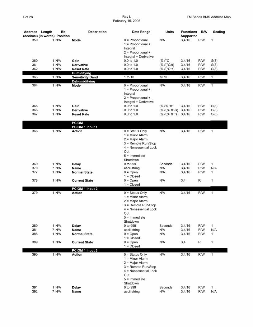
359 1 N/A Mode 0 = Proportional1 = Proportional + Integral2 = Proportional + Integral + Derivative
N/A 3,4/16 R/W 1
360 1 N/A Gain 0.0 to 1.0 (%)/°C 3,4/16 R/W S(8)361 1 N/A Derivative 0.0 to 1.0 (%)/(°C/s) 3,4/16 R/W S(8)362 1 N/A Reset Rate 0.0 to 1.0 (%)/(°C*s) 3,4/16 R/W S(8)
Humidifying363 1 N/A Sensitivity Band 1 to 10 %RH 3,4/16 R/W 1
Dehumidifying364 1 N/A Mode 0 = Proportional
1 = Proportional + Integral2 = Proportional + Integral + Derivative
N/A 3,4/16 R/W 1
365 1 N/A Gain 0.0 to 1.0 (%)/%RH 3,4/16 R/W S(8)366 1 N/A Derivative 0.0 to 1.0 (%)/(%RH/s) 3,4/16 R/W S(8)367 1 N/A Reset Rate 0.0 to 1.0 (%)/(%RH*s) 3,4/16 R/W S(8)
PCIOMPCIOM 1 Input 1
368 1 N/A Action 0 = Status Only1 = Minor Alarm2 = Major Alarm3 = Remote Run/Stop4 = Nonessential Lock Out5 = Immediate Shutdown
N/A 3,4/16 R/W 1
369 1 N/A Delay 0 to 999 Seconds 3,4/16 R/W 1370 7 N/A Name ascii string N/A 3,4/16 R/W N/A377 1 N/A Normal State 0 = Open
1 = ClosedN/A 3,4/16 R/W 1
378 1 N/A Current State 0 = Open1 = Closed
N/A 3,4 R 1
PCIOM 1 Input 2379 1 N/A Action 0 = Status Only
1 = Minor Alarm2 = Major Alarm3 = Remote Run/Stop4 = Nonessential Lock Out5 = Immediate Shutdown
N/A 3,4/16 R/W 1
380 1 N/A Delay 0 to 999 Seconds 3,4/16 R/W 1381 7 N/A Name ascii string N/A 3,4/16 R/W N/A388 1 N/A Normal State 0 = Open
1 = ClosedN/A 3,4/16 R/W 1
389 1 N/A Current State 0 = Open1 = Closed
N/A 3,4 R 1
PCIOM 1 Input 3390 1 N/A Action 0 = Status Only
1 = Minor Alarm2 = Major Alarm3 = Remote Run/Stop4 = Nonessential Lock Out5 = Immediate Shutdown
N/A 3,4/16 R/W 1
391 1 N/A Delay 0 to 999 Seconds 3,4/16 R/W 1392 7 N/A Name ascii string N/A 3,4/16 R/W N/A
5 of 28 Rev LFebruary 15, 2005
FM Series BMS Address Map
Address Length Bit Description Data Range Units Functions R/W Scaling(decimal) (in words) Position Supported
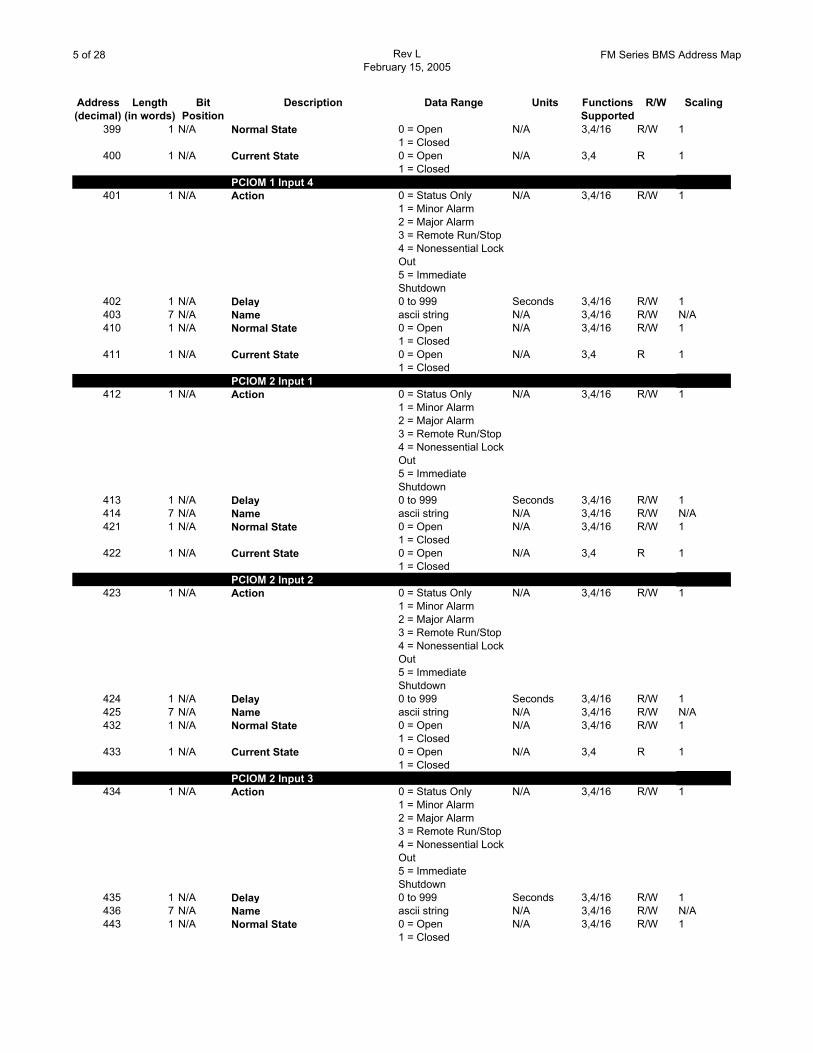
399 1 N/A Normal State 0 = Open1 = Closed
N/A 3,4/16 R/W 1
400 1 N/A Current State 0 = Open1 = Closed
N/A 3,4 R 1
PCIOM 1 Input 4401 1 N/A Action 0 = Status Only
1 = Minor Alarm2 = Major Alarm3 = Remote Run/Stop4 = Nonessential Lock Out5 = Immediate Shutdown
N/A 3,4/16 R/W 1
402 1 N/A Delay 0 to 999 Seconds 3,4/16 R/W 1403 7 N/A Name ascii string N/A 3,4/16 R/W N/A410 1 N/A Normal State 0 = Open
1 = ClosedN/A 3,4/16 R/W 1
411 1 N/A Current State 0 = Open1 = Closed
N/A 3,4 R 1
PCIOM 2 Input 1412 1 N/A Action 0 = Status Only
1 = Minor Alarm2 = Major Alarm3 = Remote Run/Stop4 = Nonessential Lock Out5 = Immediate Shutdown
N/A 3,4/16 R/W 1
413 1 N/A Delay 0 to 999 Seconds 3,4/16 R/W 1414 7 N/A Name ascii string N/A 3,4/16 R/W N/A421 1 N/A Normal State 0 = Open
1 = ClosedN/A 3,4/16 R/W 1
422 1 N/A Current State 0 = Open1 = Closed
N/A 3,4 R 1
PCIOM 2 Input 2423 1 N/A Action 0 = Status Only
1 = Minor Alarm2 = Major Alarm3 = Remote Run/Stop4 = Nonessential Lock Out5 = Immediate Shutdown
N/A 3,4/16 R/W 1
424 1 N/A Delay 0 to 999 Seconds 3,4/16 R/W 1425 7 N/A Name ascii string N/A 3,4/16 R/W N/A432 1 N/A Normal State 0 = Open
1 = ClosedN/A 3,4/16 R/W 1
433 1 N/A Current State 0 = Open1 = Closed
N/A 3,4 R 1
PCIOM 2 Input 3434 1 N/A Action 0 = Status Only
1 = Minor Alarm2 = Major Alarm3 = Remote Run/Stop4 = Nonessential Lock Out5 = Immediate Shutdown
N/A 3,4/16 R/W 1
435 1 N/A Delay 0 to 999 Seconds 3,4/16 R/W 1436 7 N/A Name ascii string N/A 3,4/16 R/W N/A443 1 N/A Normal State 0 = Open
1 = ClosedN/A 3,4/16 R/W 1
6 of 28 Rev LFebruary 15, 2005
FM Series BMS Address Map
Address Length Bit Description Data Range Units Functions R/W Scaling(decimal) (in words) Position Supported
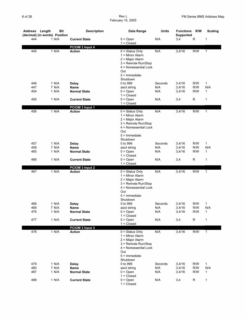
444 1 N/A Current State 0 = Open1 = Closed
N/A 3,4 R 1
PCIOM 2 Input 4445 1 N/A Action 0 = Status Only
1 = Minor Alarm2 = Major Alarm3 = Remote Run/Stop4 = Nonessential Lock Out5 = Immediate Shutdown
N/A 3,4/16 R/W 1
446 1 N/A Delay 0 to 999 Seconds 3,4/16 R/W 1447 7 N/A Name ascii string N/A 3,4/16 R/W N/A454 1 N/A Normal State 0 = Open
1 = ClosedN/A 3,4/16 R/W 1
455 1 N/A Current State 0 = Open1 = Closed
N/A 3,4 R 1
PCIOM 3 Input 1456 1 N/A Action 0 = Status Only
1 = Minor Alarm2 = Major Alarm3 = Remote Run/Stop4 = Nonessential Lock Out5 = Immediate Shutdown
N/A 3,4/16 R/W 1
457 1 N/A Delay 0 to 999 Seconds 3,4/16 R/W 1458 7 N/A Name ascii string N/A 3,4/16 R/W N/A465 1 N/A Normal State 0 = Open
1 = ClosedN/A 3,4/16 R/W 1
466 1 N/A Current State 0 = Open1 = Closed
N/A 3,4 R 1
PCIOM 3 Input 2467 1 N/A Action 0 = Status Only
1 = Minor Alarm2 = Major Alarm3 = Remote Run/Stop4 = Nonessential Lock Out5 = Immediate Shutdown
N/A 3,4/16 R/W 1
468 1 N/A Delay 0 to 999 Seconds 3,4/16 R/W 1469 7 N/A Name ascii string N/A 3,4/16 R/W N/A476 1 N/A Normal State 0 = Open
1 = ClosedN/A 3,4/16 R/W 1
477 1 N/A Current State 0 = Open1 = Closed
N/A 3,4 R 1
PCIOM 3 Input 3478 1 N/A Action 0 = Status Only
1 = Minor Alarm2 = Major Alarm3 = Remote Run/Stop4 = Nonessential Lock Out5 = Immediate Shutdown
N/A 3,4/16 R/W 1
479 1 N/A Delay 0 to 999 Seconds 3,4/16 R/W 1480 7 N/A Name ascii string N/A 3,4/16 R/W N/A487 1 N/A Normal State 0 = Open
1 = ClosedN/A 3,4/16 R/W 1
488 1 N/A Current State 0 = Open1 = Closed
N/A 3,4 R 1
7 of 28 Rev LFebruary 15, 2005
FM Series BMS Address Map
Address Length Bit Description Data Range Units Functions R/W Scaling(decimal) (in words) Position Supported
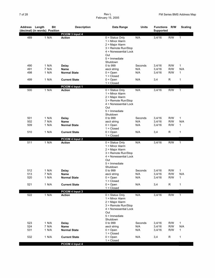
PCIOM 3 Input 4489 1 N/A Action 0 = Status Only
1 = Minor Alarm2 = Major Alarm3 = Remote Run/Stop4 = Nonessential Lock Out5 = Immediate Shutdown
N/A 3,4/16 R/W 1
490 1 N/A Delay 0 to 999 Seconds 3,4/16 R/W 1491 7 N/A Name ascii string N/A 3,4/16 R/W N/A498 1 N/A Normal State 0 = Open
1 = ClosedN/A 3,4/16 R/W 1
499 1 N/A Current State 0 = Open1 = Closed
N/A 3,4 R 1
PCIOM 4 Input 1500 1 N/A Action 0 = Status Only
1 = Minor Alarm2 = Major Alarm3 = Remote Run/Stop4 = Nonessential Lock Out5 = Immediate Shutdown
N/A 3,4/16 R/W 1
501 1 N/A Delay 0 to 999 Seconds 3,4/16 R/W 1502 7 N/A Name ascii string N/A 3,4/16 R/W N/A509 1 N/A Normal State 0 = Open
1 = ClosedN/A 3,4/16 R/W 1
510 1 N/A Current State 0 = Open1 = Closed
N/A 3,4 R 1
PCIOM 4 Input 2511 1 N/A Action 0 = Status Only
1 = Minor Alarm2 = Major Alarm3 = Remote Run/Stop4 = Nonessential Lock Out5 = Immediate Shutdown
N/A 3,4/16 R/W 1
512 1 N/A Delay 0 to 999 Seconds 3,4/16 R/W 1513 7 N/A Name ascii string N/A 3,4/16 R/W N/A520 1 N/A Normal State 0 = Open
1 = ClosedN/A 3,4/16 R/W 1
521 1 N/A Current State 0 = Open1 = Closed
N/A 3,4 R 1
PCIOM 4 Input 3522 1 N/A Action 0 = Status Only
1 = Minor Alarm2 = Major Alarm3 = Remote Run/Stop4 = Nonessential Lock Out5 = Immediate Shutdown
N/A 3,4/16 R/W 1
523 1 N/A Delay 0 to 999 Seconds 3,4/16 R/W 1524 7 N/A Name ascii string N/A 3,4/16 R/W N/A531 1 N/A Normal State 0 = Open
1 = ClosedN/A 3,4/16 R/W 1
532 1 N/A Current State 0 = Open1 = Closed
N/A 3,4 R 1
PCIOM 4 Input 4
8 of 28 Rev LFebruary 15, 2005
FM Series BMS Address Map
Address Length Bit Description Data Range Units Functions R/W Scaling(decimal) (in words) Position Supported
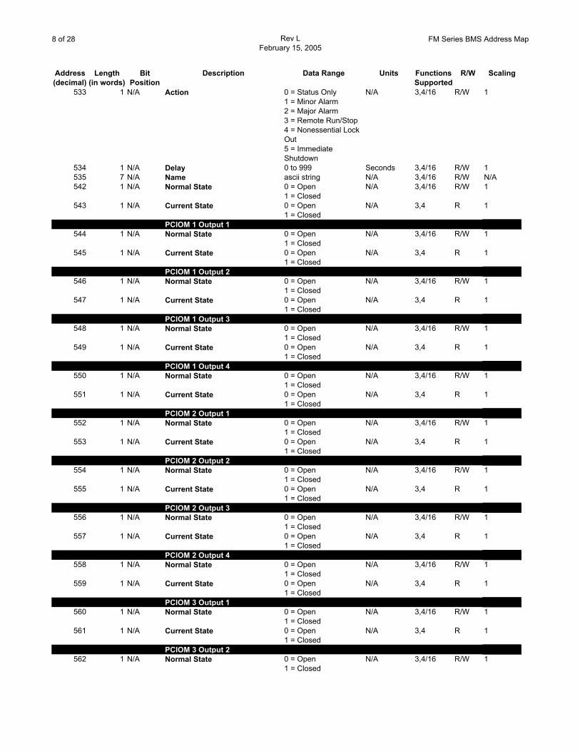
533 1 N/A Action 0 = Status Only1 = Minor Alarm2 = Major Alarm3 = Remote Run/Stop4 = Nonessential Lock Out5 = Immediate Shutdown
N/A 3,4/16 R/W 1
534 1 N/A Delay 0 to 999 Seconds 3,4/16 R/W 1535 7 N/A Name ascii string N/A 3,4/16 R/W N/A542 1 N/A Normal State 0 = Open
1 = ClosedN/A 3,4/16 R/W 1
543 1 N/A Current State 0 = Open1 = Closed
N/A 3,4 R 1
PCIOM 1 Output 1544 1 N/A Normal State 0 = Open
1 = ClosedN/A 3,4/16 R/W 1
545 1 N/A Current State 0 = Open1 = Closed
N/A 3,4 R 1
PCIOM 1 Output 2546 1 N/A Normal State 0 = Open
1 = ClosedN/A 3,4/16 R/W 1
547 1 N/A Current State 0 = Open1 = Closed
N/A 3,4 R 1
PCIOM 1 Output 3548 1 N/A Normal State 0 = Open
1 = ClosedN/A 3,4/16 R/W 1
549 1 N/A Current State 0 = Open1 = Closed
N/A 3,4 R 1
PCIOM 1 Output 4550 1 N/A Normal State 0 = Open
1 = ClosedN/A 3,4/16 R/W 1
551 1 N/A Current State 0 = Open1 = Closed
N/A 3,4 R 1
PCIOM 2 Output 1552 1 N/A Normal State 0 = Open
1 = ClosedN/A 3,4/16 R/W 1
553 1 N/A Current State 0 = Open1 = Closed
N/A 3,4 R 1
PCIOM 2 Output 2554 1 N/A Normal State 0 = Open
1 = ClosedN/A 3,4/16 R/W 1
555 1 N/A Current State 0 = Open1 = Closed
N/A 3,4 R 1
PCIOM 2 Output 3556 1 N/A Normal State 0 = Open
1 = ClosedN/A 3,4/16 R/W 1
557 1 N/A Current State 0 = Open1 = Closed
N/A 3,4 R 1
PCIOM 2 Output 4558 1 N/A Normal State 0 = Open
1 = ClosedN/A 3,4/16 R/W 1
559 1 N/A Current State 0 = Open1 = Closed
N/A 3,4 R 1
PCIOM 3 Output 1560 1 N/A Normal State 0 = Open
1 = ClosedN/A 3,4/16 R/W 1
561 1 N/A Current State 0 = Open1 = Closed
N/A 3,4 R 1
PCIOM 3 Output 2562 1 N/A Normal State 0 = Open
1 = ClosedN/A 3,4/16 R/W 1
9 of 28 Rev LFebruary 15, 2005
FM Series BMS Address Map
Address Length Bit Description Data Range Units Functions R/W Scaling(decimal) (in words) Position Supported
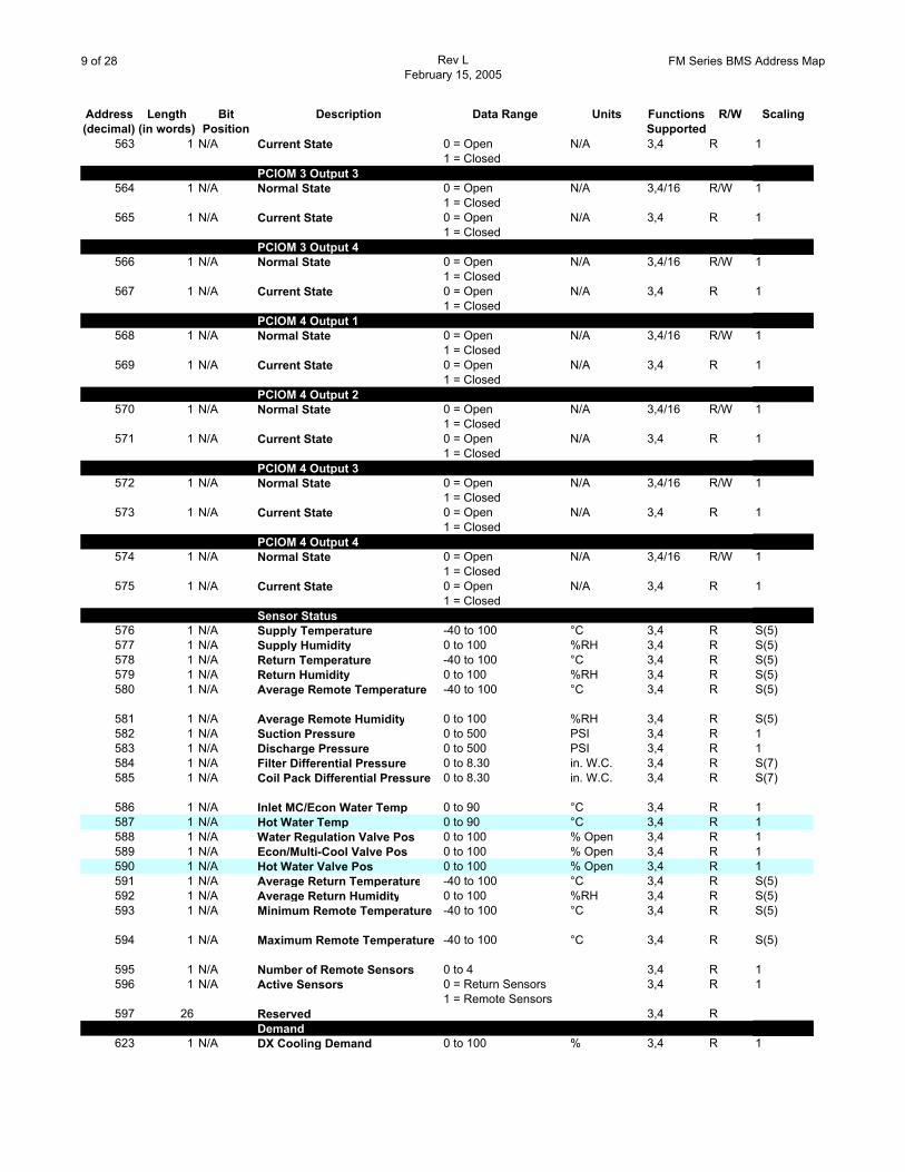
563 1 N/A Current State 0 = Open1 = Closed
N/A 3,4 R 1
PCIOM 3 Output 3564 1 N/A Normal State 0 = Open
1 = ClosedN/A 3,4/16 R/W 1
565 1 N/A Current State 0 = Open1 = Closed
N/A 3,4 R 1
PCIOM 3 Output 4566 1 N/A Normal State 0 = Open
1 = ClosedN/A 3,4/16 R/W 1
567 1 N/A Current State 0 = Open1 = Closed
N/A 3,4 R 1
PCIOM 4 Output 1568 1 N/A Normal State 0 = Open
1 = ClosedN/A 3,4/16 R/W 1
569 1 N/A Current State 0 = Open1 = Closed
N/A 3,4 R 1
PCIOM 4 Output 2570 1 N/A Normal State 0 = Open
1 = ClosedN/A 3,4/16 R/W 1
571 1 N/A Current State 0 = Open1 = Closed
N/A 3,4 R 1
PCIOM 4 Output 3572 1 N/A Normal State 0 = Open
1 = ClosedN/A 3,4/16 R/W 1
573 1 N/A Current State 0 = Open1 = Closed
N/A 3,4 R 1
PCIOM 4 Output 4574 1 N/A Normal State 0 = Open
1 = ClosedN/A 3,4/16 R/W 1
575 1 N/A Current State 0 = Open1 = Closed
N/A 3,4 R 1
Sensor Status576 1 N/A Supply Temperature -40 to 100 °C 3,4 R S(5)577 1 N/A Supply Humidity 0 to 100 %RH 3,4 R S(5)578 1 N/A Return Temperature -40 to 100 °C 3,4 R S(5)579 1 N/A Return Humidity 0 to 100 %RH 3,4 R S(5)580 1 N/A Average Remote Temperature -40 to 100 °C 3,4 R S(5)
581 1 N/A Average Remote Humidity 0 to 100 %RH 3,4 R S(5)582 1 N/A Suction Pressure 0 to 500 PSI 3,4 R 1583 1 N/A Discharge Pressure 0 to 500 PSI 3,4 R 1584 1 N/A Filter Differential Pressure 0 to 8.30 in. W.C. 3,4 R S(7)585 1 N/A Coil Pack Differential Pressure 0 to 8.30 in. W.C. 3,4 R S(7)
586 1 N/A Inlet MC/Econ Water Temp 0 to 90 °C 3,4 R 1587 1 N/A Hot Water Temp 0 to 90 °C 3,4 R 1588 1 N/A Water Regulation Valve Pos 0 to 100 % Open 3,4 R 1589 1 N/A Econ/Multi-Cool Valve Pos 0 to 100 % Open 3,4 R 1590 1 N/A Hot Water Valve Pos 0 to 100 % Open 3,4 R 1591 1 N/A Average Return Temperature -40 to 100 °C 3,4 R S(5)592 1 N/A Average Return Humidity 0 to 100 %RH 3,4 R S(5)593 1 N/A Minimum Remote Temperature -40 to 100 °C 3,4 R S(5)
594 1 N/A Maximum Remote Temperature -40 to 100 °C 3,4 R S(5)
595 1 N/A Number of Remote Sensors 0 to 4 3,4 R 1596 1 N/A Active Sensors 0 = Return Sensors
1 = Remote Sensors3,4 R 1
597 26 Reserved 3,4 RDemand
623 1 N/A DX Cooling Demand 0 to 100 % 3,4 R 1
10 of 28 Rev LFebruary 15, 2005
FM Series BMS Address Map
Address Length Bit Description Data Range Units Functions R/W Scaling(decimal) (in words) Position Supported
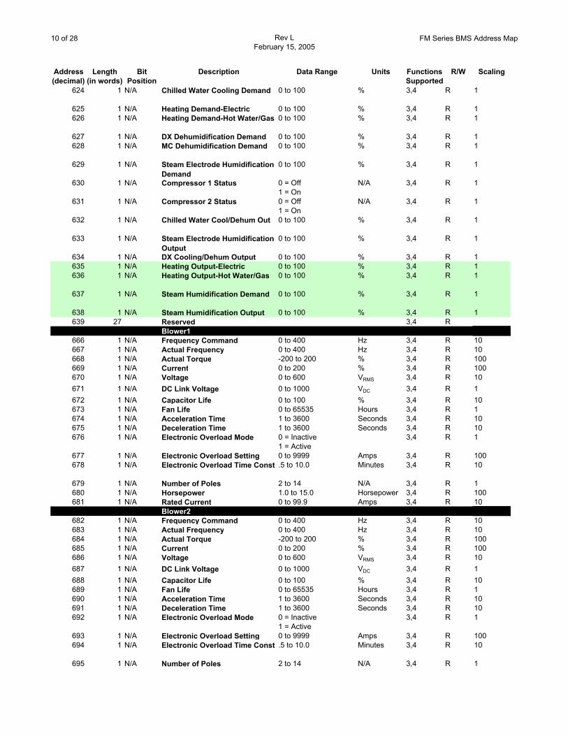
624 1 N/A Chilled Water Cooling Demand 0 to 100 % 3,4 R 1
625 1 N/A Heating Demand-Electric 0 to 100 % 3,4 R 1626 1 N/A Heating Demand-Hot Water/Gas 0 to 100 % 3,4 R 1
627 1 N/A DX Dehumidification Demand 0 to 100 % 3,4 R 1628 1 N/A MC Dehumidification Demand 0 to 100 % 3,4 R 1
629 1 N/A Steam Electrode Humidification Demand
0 to 100 % 3,4 R 1
630 1 N/A Compressor 1 Status 0 = Off1 = On
N/A 3,4 R 1
631 1 N/A Compressor 2 Status 0 = Off1 = On
N/A 3,4 R 1
632 1 N/A Chilled Water Cool/Dehum Out 0 to 100 % 3,4 R 1
633 1 N/A Steam Electrode Humidification Output
0 to 100 % 3,4 R 1
634 1 N/A DX Cooling/Dehum Output 0 to 100 % 3,4 R 1635 1 N/A Heating Output-Electric 0 to 100 % 3,4 R 1636 1 N/A Heating Output-Hot Water/Gas 0 to 100 % 3,4 R 1
637 1 N/A Steam Humidification Demand 0 to 100 % 3,4 R 1
638 1 N/A Steam Humidification Output 0 to 100 % 3,4 R 1639 27 Reserved 3,4 R
Blower1666 1 N/A Frequency Command 0 to 400 Hz 3,4 R 10667 1 N/A Actual Frequency 0 to 400 Hz 3,4 R 10668 1 N/A Actual Torque -200 to 200 % 3,4 R 100669 1 N/A Current 0 to 200 % 3,4 R 100670 1 N/A Voltage 0 to 600 VRMS 3,4 R 10671 1 N/A DC Link Voltage 0 to 1000 VDC 3,4 R 1672 1 N/A Capacitor Life 0 to 100 % 3,4 R 10673 1 N/A Fan Life 0 to 65535 Hours 3,4 R 1674 1 N/A Acceleration Time 1 to 3600 Seconds 3,4 R 10675 1 N/A Deceleration Time 1 to 3600 Seconds 3,4 R 10676 1 N/A Electronic Overload Mode 0 = Inactive
1 = Active3,4 R 1
677 1 N/A Electronic Overload Setting 0 to 9999 Amps 3,4 R 100678 1 N/A Electronic Overload Time Const .5 to 10.0 Minutes 3,4 R 10
679 1 N/A Number of Poles 2 to 14 N/A 3,4 R 1680 1 N/A Horsepower 1.0 to 15.0 Horsepower 3,4 R 100681 1 N/A Rated Current 0 to 99.9 Amps 3,4 R 10
Blower2682 1 N/A Frequency Command 0 to 400 Hz 3,4 R 10683 1 N/A Actual Frequency 0 to 400 Hz 3,4 R 10684 1 N/A Actual Torque -200 to 200 % 3,4 R 100685 1 N/A Current 0 to 200 % 3,4 R 100686 1 N/A Voltage 0 to 600 VRMS 3,4 R 10687 1 N/A DC Link Voltage 0 to 1000 VDC 3,4 R 1688 1 N/A Capacitor Life 0 to 100 % 3,4 R 10689 1 N/A Fan Life 0 to 65535 Hours 3,4 R 1690 1 N/A Acceleration Time 1 to 3600 Seconds 3,4 R 10691 1 N/A Deceleration Time 1 to 3600 Seconds 3,4 R 10692 1 N/A Electronic Overload Mode 0 = Inactive
1 = Active3,4 R 1
693 1 N/A Electronic Overload Setting 0 to 9999 Amps 3,4 R 100694 1 N/A Electronic Overload Time Const .5 to 10.0 Minutes 3,4 R 10
695 1 N/A Number of Poles 2 to 14 N/A 3,4 R 1
11 of 28 Rev LFebruary 15, 2005
FM Series BMS Address Map
Address Length Bit Description Data Range Units Functions R/W Scaling(decimal) (in words) Position Supported
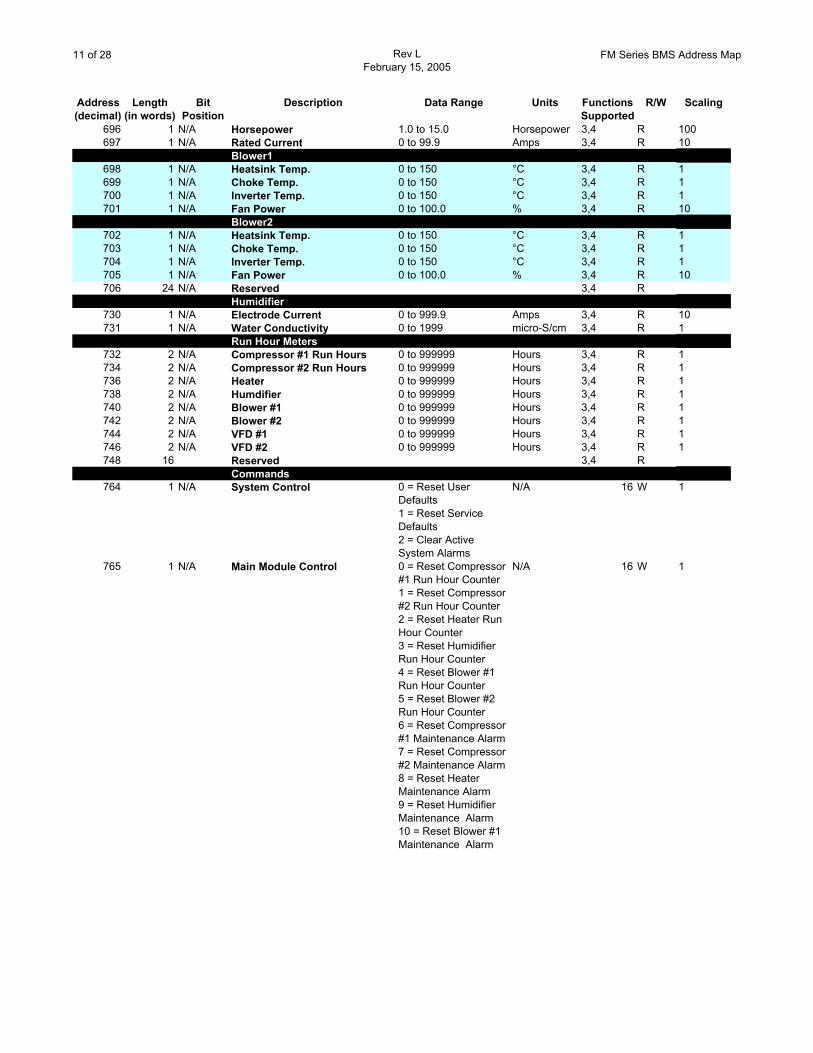
696 1 N/A Horsepower 1.0 to 15.0 Horsepower 3,4 R 100697 1 N/A Rated Current 0 to 99.9 Amps 3,4 R 10
Blower1698 1 N/A Heatsink Temp. 0 to 150 °C 3,4 R 1699 1 N/A Choke Temp. 0 to 150 °C 3,4 R 1700 1 N/A Inverter Temp. 0 to 150 °C 3,4 R 1701 1 N/A Fan Power 0 to 100.0 % 3,4 R 10
Blower2702 1 N/A Heatsink Temp. 0 to 150 °C 3,4 R 1703 1 N/A Choke Temp. 0 to 150 °C 3,4 R 1704 1 N/A Inverter Temp. 0 to 150 °C 3,4 R 1705 1 N/A Fan Power 0 to 100.0 % 3,4 R 10706 24 N/A Reserved 3,4 R
Humidifier730 1 N/A Electrode Current 0 to 999.9 Amps 3,4 R 10731 1 N/A Water Conductivity 0 to 1999 micro-S/cm 3,4 R 1
Run Hour Meters732 2 N/A Compressor #1 Run Hours 0 to 999999 Hours 3,4 R 1734 2 N/A Compressor #2 Run Hours 0 to 999999 Hours 3,4 R 1736 2 N/A Heater 0 to 999999 Hours 3,4 R 1738 2 N/A Humdifier 0 to 999999 Hours 3,4 R 1740 2 N/A Blower #1 0 to 999999 Hours 3,4 R 1742 2 N/A Blower #2 0 to 999999 Hours 3,4 R 1744 2 N/A VFD #1 0 to 999999 Hours 3,4 R 1746 2 N/A VFD #2 0 to 999999 Hours 3,4 R 1748 16 Reserved 3,4 R
Commands764 1 N/A System Control 0 = Reset User
Defaults1 = Reset Service Defaults2 = Clear Active System Alarms
N/A 16 W 1
765 1 N/A Main Module Control 0 = Reset Compressor #1 Run Hour Counter1 = Reset Compressor #2 Run Hour Counter2 = Reset Heater Run Hour Counter3 = Reset Humidifier Run Hour Counter4 = Reset Blower #1 Run Hour Counter5 = Reset Blower #2 Run Hour Counter6 = Reset Compressor #1 Maintenance Alarm7 = Reset Compressor #2 Maintenance Alarm8 = Reset Heater Maintenance Alarm9 = Reset Humidifier Maintenance Alarm10 = Reset Blower #1 Maintenance Alarm
N/A 16 W 1
12 of 28 Rev LFebruary 15, 2005
FM Series BMS Address Map
Address Length Bit Description Data Range Units Functions R/W Scaling(decimal) (in words) Position Supported
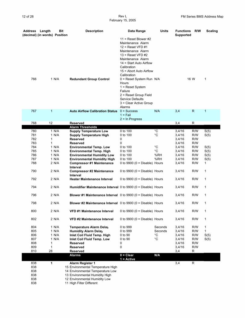
11 = Reset Blower #2 Maintenance Alarm12 = Reset VFD #1 Maintenance Alarm13 = Reset VFD #2 Maintenance Alarm14 = Start Auto Airflow Calibration15 = Abort Auto Airflow Calibration
766 1 N/A Redundant Group Control 0 = Reset System Run Hours1 = Reset System Failure2 = Reset Group Field Service Defaults3 = Clear Active Group Alarms
N/A 16 W 1
767 1 Auto Airflow Calibration Status 0 = Success1 = Fail2 = In Progress
N/A 3,4 R 1
768 12 Reserved 3,4 RAlarm Thresholds
780 1 N/A Supply Temperature Low 0 to 100 °C 3,4/16 R/W S(5)781 1 N/A Supply Temperature High 0 to 100 °C 3,4/16 R/W S(5)782 1 Reserved 0 3,4/16 R/W783 1 Reserved 0 3,4/16 R/W784 1 N/A Environmental Temp. Low 0 to 100 °C 3,4/16 R/W S(5)785 1 N/A Environmental Temp. High 0 to 100 °C 3,4/16 R/W S(5)786 1 N/A Environmental Humidity Low 0 to 100 %RH 3,4/16 R/W S(5)787 1 N/A Environmental Humidity High 0 to 100 %RH 3,4/16 R/W S(5)788 2 N/A Compressor #1 Maintenance
Interval0 to 9900 (0 = Disable) Hours 3,4/16 R/W 1
790 2 N/A Compressor #2 Maintenance Interval
0 to 9900 (0 = Disable) Hours 3,4/16 R/W 1
792 2 N/A Heater Maintenance Interval 0 to 9900 (0 = Disable) Hours 3,4/16 R/W 1
794 2 N/A Humidifier Maintenance Interval 0 to 9900 (0 = Disable) Hours 3,4/16 R/W 1
796 2 N/A Blower #1 Maintenance Interval 0 to 9900 (0 = Disable) Hours 3,4/16 R/W 1
798 2 N/A Blower #2 Maintenance Interval 0 to 9900 (0 = Disable) Hours 3,4/16 R/W 1
800 2 N/A VFD #1 Maintenance Interval 0 to 9900 (0 = Disable) Hours 3,4/16 R/W 1
802 2 N/A VFD #2 Maintenance Interval 0 to 9900 (0 = Disable) Hours 3,4/16 R/W 1
804 1 N/A Temperature Alarm Delay 0 to 999 Seconds 3,4/16 R/W 1805 1 N/A Humidity Alarm Delay 0 to 999 Seconds 3,4/16 R/W 1806 1 N/A Inlet Coil Fluid Temp. High 0 to 90 °C 3,4/16 R/W S(5)807 1 N/A Inlet Coil Fluid Temp. Low 0 to 90 °C 3,4/16 R/W S(5)808 1 Reserved 0 3,4/16 R/W809 1 Reserved 0 3,4/16 R/W810 28 Reserved 3,4 R
Alarms 0 = Clear N/A1 = Active
838 1 Alarm Register 1 3,4 R838 15 Environmental Temperature High838 14 Environmental Temperature Low 838 13 Environmental Humidity High838 12 Environmental Humidity Low838 11 High Filter Different
13 of 28 Rev LFebruary 15, 2005
FM Series BMS Address Map
Address Length Bit Description Data Range Units Functions R/W Scaling(decimal) (in words) Position Supported
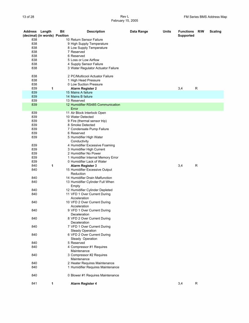
838 10 Return Sensor Failure838 9 High Supply Temperature838 8 Low Supply Temperature838 7 Reserved838 6 Reserved838 5 Loss or Low Airflow838 4 Supply Sensor Failure838 3 Water Regulator Actuator Failure
838 2 PC/Multicool Actuator Failure838 1 High Head Pressure838 0 Low Suction Pressure839 1 Alarm Register 2 3,4 R839 15 Mains A failure839 14 Mains B failure839 13 Reserved839 12 Humidifier RS485 Communication
Error839 11 Air Block Interlock Open839 10 Water Detected839 9 Fire (thermal sensor trip)839 8 Smoke Detected839 7 Condensate Pump Failure839 6 Reserved839 5 Humidifier High Water
Conductivity839 4 Humidifier Excessive Foaming839 3 Humidifier High Current839 2 Humidifier No Power839 1 Humidifier Internal Memory Error839 0 Humidifier Lack of Water840 1 Alarm Register 3 3,4 R840 15 Humidifier Excessive Output
Reduction840 14 Humidifier Drain Malfunction840 13 Humidifier Cylinder Full When
Empty840 12 Humidifier Cylinder Depleted840 11 VFD 1 Over Current During
Acceleration840 10 VFD 2 Over Current During
Acceleration840 9 VFD 1 Over Current During
Deceleration840 8 VFD 2 Over Current During
Deceleration840 7 VFD 1 Over Current During
Steady Operation840 6 VFD 2 Over Current During
Steady Operation840 5 Reserved840 4 Compressor #1 Requires
Maintenance840 3 Compressor #2 Requires
Maintenance840 2 Heater Requires Maintenance840 1 Humidifier Requires Maintenance
840 0 Blower #1 Requires Maintenance
841 1 Alarm Register 4 3,4 R
14 of 28 Rev LFebruary 15, 2005
FM Series BMS Address Map
Address Length Bit Description Data Range Units Functions R/W Scaling(decimal) (in words) Position Supported
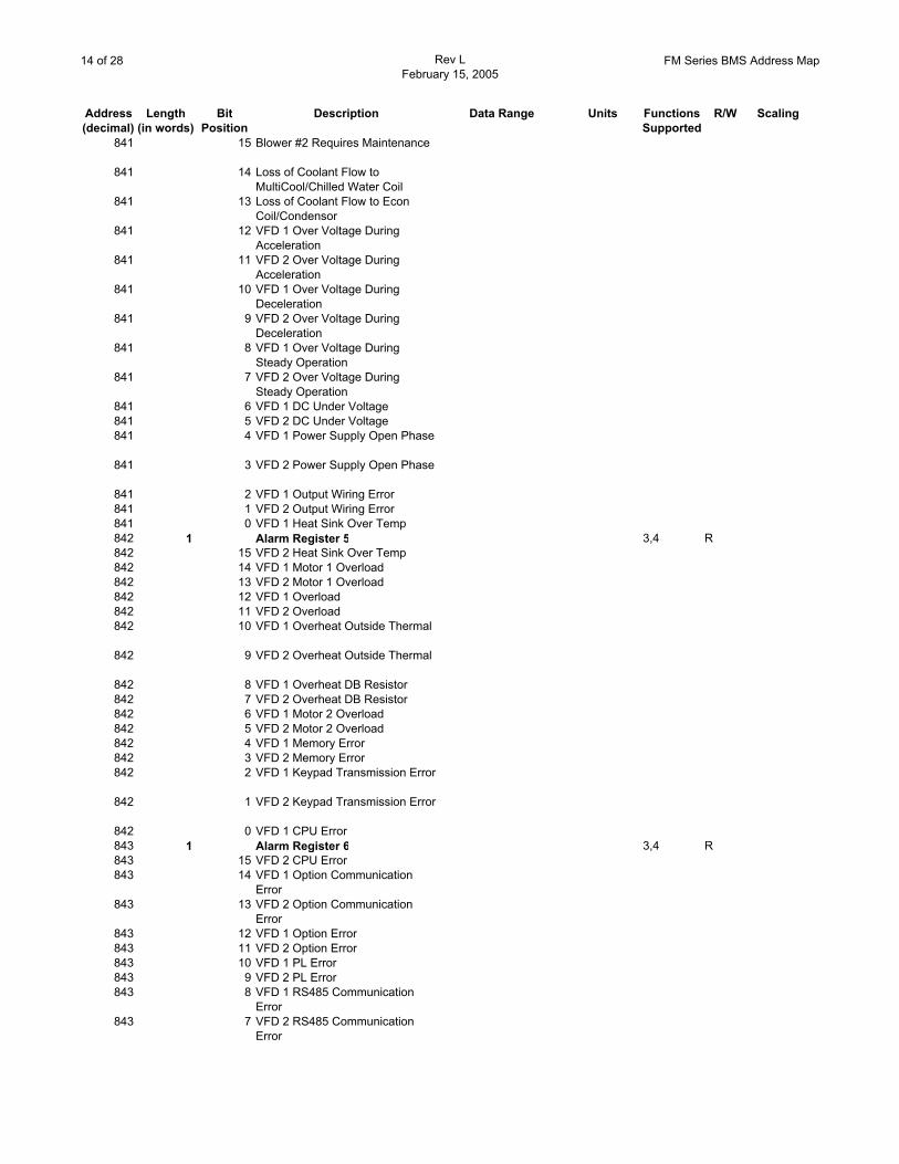
841 15 Blower #2 Requires Maintenance
841 14 Loss of Coolant Flow to MultiCool/Chilled Water Coil
841 13 Loss of Coolant Flow to Econ Coil/Condensor
841 12 VFD 1 Over Voltage During Acceleration
841 11 VFD 2 Over Voltage During Acceleration
841 10 VFD 1 Over Voltage During Deceleration
841 9 VFD 2 Over Voltage During Deceleration
841 8 VFD 1 Over Voltage During Steady Operation
841 7 VFD 2 Over Voltage During Steady Operation
841 6 VFD 1 DC Under Voltage841 5 VFD 2 DC Under Voltage841 4 VFD 1 Power Supply Open Phase
841 3 VFD 2 Power Supply Open Phase
841 2 VFD 1 Output Wiring Error841 1 VFD 2 Output Wiring Error841 0 VFD 1 Heat Sink Over Temp842 1 Alarm Register 5 3,4 R842 15 VFD 2 Heat Sink Over Temp842 14 VFD 1 Motor 1 Overload842 13 VFD 2 Motor 1 Overload842 12 VFD 1 Overload842 11 VFD 2 Overload842 10 VFD 1 Overheat Outside Thermal
842 9 VFD 2 Overheat Outside Thermal
842 8 VFD 1 Overheat DB Resistor842 7 VFD 2 Overheat DB Resistor842 6 VFD 1 Motor 2 Overload842 5 VFD 2 Motor 2 Overload842 4 VFD 1 Memory Error842 3 VFD 2 Memory Error842 2 VFD 1 Keypad Transmission Error
842 1 VFD 2 Keypad Transmission Error
842 0 VFD 1 CPU Error843 1 Alarm Register 6 3,4 R843 15 VFD 2 CPU Error843 14 VFD 1 Option Communication
Error843 13 VFD 2 Option Communication
Error843 12 VFD 1 Option Error843 11 VFD 2 Option Error843 10 VFD 1 PL Error843 9 VFD 2 PL Error843 8 VFD 1 RS485 Communication
Error843 7 VFD 2 RS485 Communication
Error
15 of 28 Rev LFebruary 15, 2005
FM Series BMS Address Map
Address Length Bit Description Data Range Units Functions R/W Scaling(decimal) (in words) Position Supported
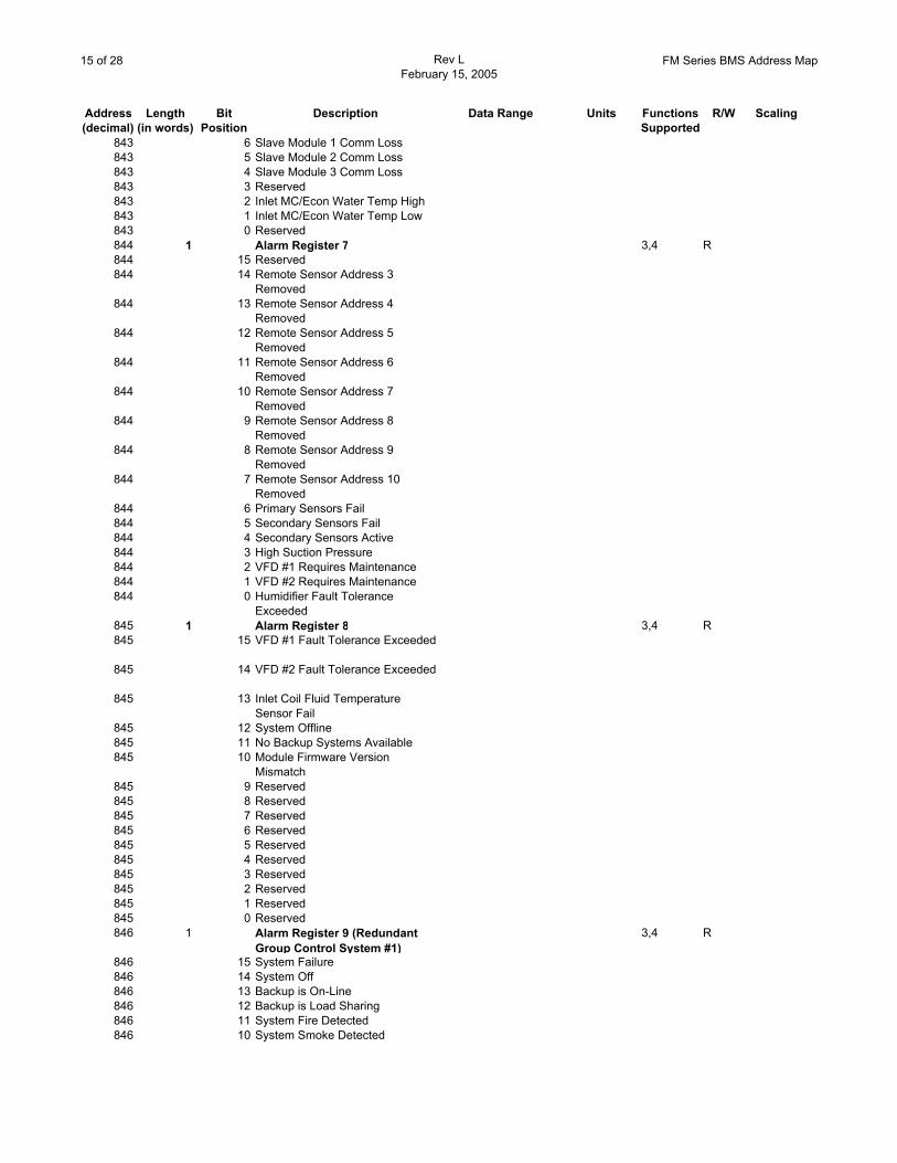
843 6 Slave Module 1 Comm Loss843 5 Slave Module 2 Comm Loss843 4 Slave Module 3 Comm Loss843 3 Reserved843 2 Inlet MC/Econ Water Temp High843 1 Inlet MC/Econ Water Temp Low843 0 Reserved844 1 Alarm Register 7 3,4 R844 15 Reserved844 14 Remote Sensor Address 3
Removed844 13 Remote Sensor Address 4
Removed844 12 Remote Sensor Address 5
Removed844 11 Remote Sensor Address 6
Removed844 10 Remote Sensor Address 7
Removed844 9 Remote Sensor Address 8
Removed844 8 Remote Sensor Address 9
Removed844 7 Remote Sensor Address 10
Removed844 6 Primary Sensors Fail844 5 Secondary Sensors Fail844 4 Secondary Sensors Active844 3 High Suction Pressure844 2 VFD #1 Requires Maintenance844 1 VFD #2 Requires Maintenance844 0 Humidifier Fault Tolerance
Exceeded845 1 Alarm Register 8 3,4 R845 15 VFD #1 Fault Tolerance Exceeded
845 14 VFD #2 Fault Tolerance Exceeded
845 13 Inlet Coil Fluid Temperature Sensor Fail
845 12 System Offline845 11 No Backup Systems Available845 10 Module Firmware Version
Mismatch845 9 Reserved845 8 Reserved845 7 Reserved845 6 Reserved845 5 Reserved845 4 Reserved845 3 Reserved845 2 Reserved845 1 Reserved845 0 Reserved846 1 Alarm Register 9 (Redundant
Group Control System #1)3,4 R
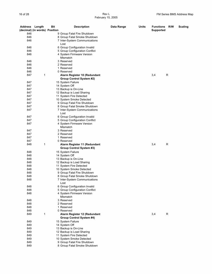
846 15 System Failure846 14 System Off846 13 Backup is On-Line846 12 Backup is Load Sharing846 11 System Fire Detected846 10 System Smoke Detected
16 of 28 Rev LFebruary 15, 2005
FM Series BMS Address Map
Address Length Bit Description Data Range Units Functions R/W Scaling(decimal) (in words) Position Supported
846 9 Group Fatal Fire Shutdown846 8 Group Fatal Smoke Shutdown846 7 Inter-System Communications
Lost846 6 Group Configuration Invalid846 5 Group Configuration Conflict846 4 System Firmware Version
Mismatch846 3 Reserved846 2 Reserved846 1 Reserved846 0 Reserved847 1 Alarm Register 10 (Redundant
Group Control System #2)3,4 R
847 15 System Failure847 14 System Off847 13 Backup is On-Line847 12 Backup is Load Sharing847 11 System Fire Detected847 10 System Smoke Detected847 9 Group Fatal Fire Shutdown847 8 Group Fatal Smoke Shutdown847 7 Inter-System Communications
Lost847 6 Group Configuration Invalid847 5 Group Configuration Conflict847 4 System Firmware Version
Mismatch847 3 Reserved847 2 Reserved847 1 Reserved847 0 Reserved848 1 Alarm Register 11 (Redundant
Group Control System #3)3,4 R
848 15 System Failure848 14 System Off848 13 Backup is On-Line848 12 Backup is Load Sharing848 11 System Fire Detected848 10 System Smoke Detected848 9 Group Fatal Fire Shutdown848 8 Group Fatal Smoke Shutdown848 7 Inter-System Communications
Lost848 6 Group Configuration Invalid848 5 Group Configuration Conflict848 4 System Firmware Version
Mismatch848 3 Reserved848 2 Reserved848 1 Reserved848 0 Reserved849 1 Alarm Register 12 (Redundant
Group Control System #4)3,4 R
849 15 System Failure849 14 System Off849 13 Backup is On-Line849 12 Backup is Load Sharing849 11 System Fire Detected849 10 System Smoke Detected849 9 Group Fatal Fire Shutdown849 8 Group Fatal Smoke Shutdown
17 of 28 Rev LFebruary 15, 2005
FM Series BMS Address Map
Address Length Bit Description Data Range Units Functions R/W Scaling(decimal) (in words) Position Supported
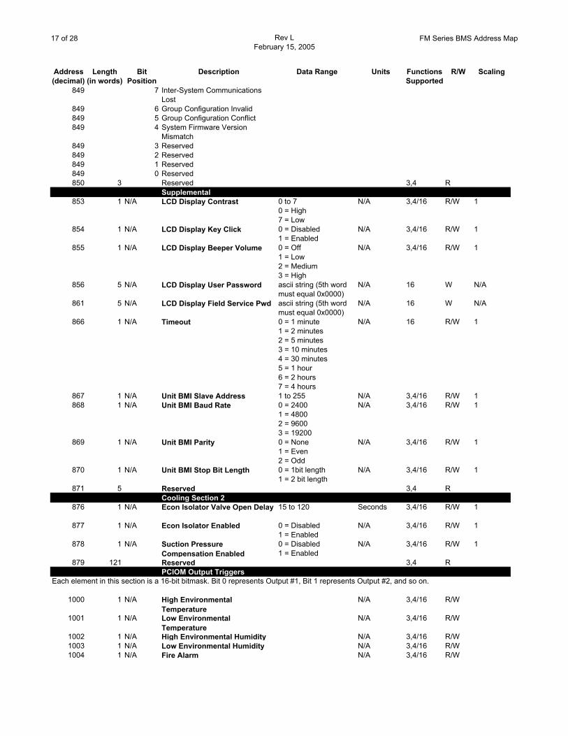
849 7 Inter-System Communications Lost
849 6 Group Configuration Invalid849 5 Group Configuration Conflict849 4 System Firmware Version
Mismatch849 3 Reserved849 2 Reserved849 1 Reserved849 0 Reserved850 3 Reserved 3,4 R
Supplemental853 1 N/A LCD Display Contrast 0 to 7
0 = High7 = Low
N/A 3,4/16 R/W 1
854 1 N/A LCD Display Key Click 0 = Disabled1 = Enabled
N/A 3,4/16 R/W 1
855 1 N/A LCD Display Beeper Volume 0 = Off1 = Low2 = Medium3 = High
N/A 3,4/16 R/W 1
856 5 N/A LCD Display User Password ascii string (5th word must equal 0x0000)
N/A 16 W N/A
861 5 N/A LCD Display Field Service Pwd ascii string (5th word must equal 0x0000)
N/A 16 W N/A
866 1 N/A Timeout 0 = 1 minute1 = 2 minutes2 = 5 minutes3 = 10 minutes4 = 30 minutes5 = 1 hour6 = 2 hours7 = 4 hours
N/A 16 R/W 1
867 1 N/A Unit BMI Slave Address 1 to 255 N/A 3,4/16 R/W 1868 1 N/A Unit BMI Baud Rate 0 = 2400
1 = 48002 = 96003 = 19200
N/A 3,4/16 R/W 1
869 1 N/A Unit BMI Parity 0 = None1 = Even2 = Odd
N/A 3,4/16 R/W 1
870 1 N/A Unit BMI Stop Bit Length 0 = 1bit length1 = 2 bit length
N/A 3,4/16 R/W 1
871 5 Reserved 3,4 RCooling Section 2
876 1 N/A Econ Isolator Valve Open Delay 15 to 120 Seconds 3,4/16 R/W 1
877 1 N/A Econ Isolator Enabled 0 = Disabled1 = Enabled
N/A 3,4/16 R/W 1
878 1 N/A Suction Pressure Compensation Enabled
0 = Disabled1 = Enabled
N/A 3,4/16 R/W 1
879 121 Reserved 3,4 RPCIOM Output Triggers
Each element in this section is a 16-bit bitmask. Bit 0 represents Output #1, Bit 1 represents Output #2, and so on.
1000 1 N/A High Environmental Temperature
N/A 3,4/16 R/W
1001 1 N/A Low Environmental Temperature
N/A 3,4/16 R/W
1002 1 N/A High Environmental Humidity N/A 3,4/16 R/W1003 1 N/A Low Environmental Humidity N/A 3,4/16 R/W1004 1 N/A Fire Alarm N/A 3,4/16 R/W
18 of 28 Rev LFebruary 15, 2005
FM Series BMS Address Map
Address Length Bit Description Data Range Units Functions R/W Scaling(decimal) (in words) Position Supported
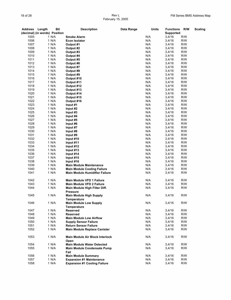
1005 1 N/A Smoke Alarm N/A 3,4/16 R/W1006 1 N/A Econ Isolator N/A 3,4/16 R/W1007 1 N/A Output #1 N/A 3,4/16 R/W1008 1 N/A Output #2 N/A 3,4/16 R/W1009 1 N/A Output #3 N/A 3,4/16 R/W1010 1 N/A Output #4 N/A 3,4/16 R/W1011 1 N/A Output #5 N/A 3,4/16 R/W1012 1 N/A Output #6 N/A 3,4/16 R/W1013 1 N/A Output #7 N/A 3,4/16 R/W1014 1 N/A Output #8 N/A 3,4/16 R/W1015 1 N/A Output #9 N/A 3,4/16 R/W1016 1 N/A Output #10 N/A 3,4/16 R/W1017 1 N/A Output #11 N/A 3,4/16 R/W1018 1 N/A Output #12 N/A 3,4/16 R/W1019 1 N/A Output #13 N/A 3,4/16 R/W1020 1 N/A Output #14 N/A 3,4/16 R/W1021 1 N/A Output #15 N/A 3,4/16 R/W1022 1 N/A Output #16 N/A 3,4/16 R/W1023 1 N/A Input #1 N/A 3,4/16 R/W1024 1 N/A Input #2 N/A 3,4/16 R/W1025 1 N/A Input #3 N/A 3,4/16 R/W1026 1 N/A Input #4 N/A 3,4/16 R/W1027 1 N/A Input #5 N/A 3,4/16 R/W1028 1 N/A Input #6 N/A 3,4/16 R/W1029 1 N/A Input #7 N/A 3,4/16 R/W1030 1 N/A Input #8 N/A 3,4/16 R/W1031 1 N/A Input #9 N/A 3,4/16 R/W1032 1 N/A Input #10 N/A 3,4/16 R/W1033 1 N/A Input #11 N/A 3,4/16 R/W1034 1 N/A Input #12 N/A 3,4/16 R/W1035 1 N/A Input #13 N/A 3,4/16 R/W1036 1 N/A Input #14 N/A 3,4/16 R/W1037 1 N/A Input #15 N/A 3,4/16 R/W1038 1 N/A Input #16 N/A 3,4/16 R/W1039 1 N/A Main Module Maintenance N/A 3,4/16 R/W1040 1 N/A Main Module Cooling Failure N/A 3,4/16 R/W1041 1 N/A Main Module Humidifier Failure N/A 3,4/16 R/W
1042 1 N/A Main Module VFD 1 Failure N/A 3,4/16 R/W1043 1 N/A Main Module VFD 2 Failure N/A 3,4/16 R/W1044 1 N/A Main Module High Filter Diff.
PressureN/A 3,4/16 R/W
1045 1 N/A Main Module High Supply Temperature
N/A 3,4/16 R/W
1046 1 N/A Main Module Low Supply Temperature
N/A 3,4/16 R/W
1047 1 N/A Reserved N/A 3,4/16 R/W1048 1 N/A Reserved N/A 3,4/16 R/W1049 1 N/A Main Module Low Airflow N/A 3,4/16 R/W1050 1 N/A Supply Sensor Failure N/A 3,4/16 R/W1051 1 N/A Return Sensor Failure N/A 3,4/16 R/W1052 1 N/A Main Module Replace Canister N/A 3,4/16 R/W
1053 1 N/A Main Module Air Block Interlock Open
N/A 3,4/16 R/W
1054 1 N/A Main Module Water Detected N/A 3,4/16 R/W1055 1 N/A Main Module Condensate Pump
FailN/A 3,4/16 R/W
1056 1 N/A Main Module Summary N/A 3,4/16 R/W1057 1 N/A Expansion #1 Maintenance N/A 3,4/16 R/W1058 1 N/A Expansion #1 Cooling Failure N/A 3,4/16 R/W
19 of 28 Rev LFebruary 15, 2005
FM Series BMS Address Map
Address Length Bit Description Data Range Units Functions R/W Scaling(decimal) (in words) Position Supported
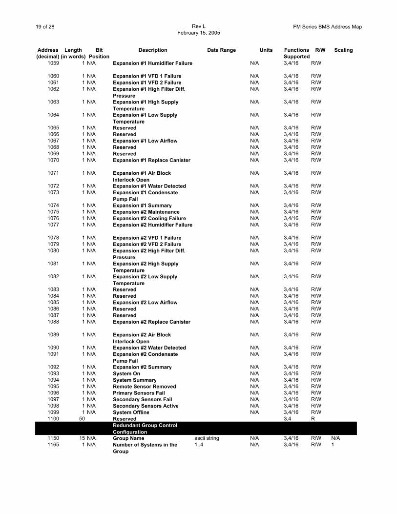
1059 1 N/A Expansion #1 Humidifier Failure N/A 3,4/16 R/W
1060 1 N/A Expansion #1 VFD 1 Failure N/A 3,4/16 R/W1061 1 N/A Expansion #1 VFD 2 Failure N/A 3,4/16 R/W1062 1 N/A Expansion #1 High Filter Diff.
PressureN/A 3,4/16 R/W
1063 1 N/A Expansion #1 High Supply Temperature
N/A 3,4/16 R/W
1064 1 N/A Expansion #1 Low Supply Temperature
N/A 3,4/16 R/W
1065 1 N/A Reserved N/A 3,4/16 R/W1066 1 N/A Reserved N/A 3,4/16 R/W1067 1 N/A Expansion #1 Low Airflow N/A 3,4/16 R/W1068 1 N/A Reserved N/A 3,4/16 R/W1069 1 N/A Reserved N/A 3,4/16 R/W1070 1 N/A Expansion #1 Replace Canister N/A 3,4/16 R/W
1071 1 N/A Expansion #1 Air Block Interlock Open
N/A 3,4/16 R/W
1072 1 N/A Expansion #1 Water Detected N/A 3,4/16 R/W1073 1 N/A Expansion #1 Condensate
Pump FailN/A 3,4/16 R/W
1074 1 N/A Expansion #1 Summary N/A 3,4/16 R/W1075 1 N/A Expansion #2 Maintenance N/A 3,4/16 R/W1076 1 N/A Expansion #2 Cooling Failure N/A 3,4/16 R/W1077 1 N/A Expansion #2 Humidifier Failure N/A 3,4/16 R/W
1078 1 N/A Expansion #2 VFD 1 Failure N/A 3,4/16 R/W1079 1 N/A Expansion #2 VFD 2 Failure N/A 3,4/16 R/W1080 1 N/A Expansion #2 High Filter Diff.
PressureN/A 3,4/16 R/W
1081 1 N/A Expansion #2 High Supply Temperature
N/A 3,4/16 R/W
1082 1 N/A Expansion #2 Low Supply Temperature
N/A 3,4/16 R/W
1083 1 N/A Reserved N/A 3,4/16 R/W1084 1 N/A Reserved N/A 3,4/16 R/W1085 1 N/A Expansion #2 Low Airflow N/A 3,4/16 R/W1086 1 N/A Reserved N/A 3,4/16 R/W1087 1 N/A Reserved N/A 3,4/16 R/W1088 1 N/A Expansion #2 Replace Canister N/A 3,4/16 R/W
1089 1 N/A Expansion #2 Air Block Interlock Open
N/A 3,4/16 R/W
1090 1 N/A Expansion #2 Water Detected N/A 3,4/16 R/W1091 1 N/A Expansion #2 Condensate
Pump FailN/A 3,4/16 R/W
1092 1 N/A Expansion #2 Summary N/A 3,4/16 R/W1093 1 N/A System On N/A 3,4/16 R/W1094 1 N/A System Summary N/A 3,4/16 R/W1095 1 N/A Remote Sensor Removed N/A 3,4/16 R/W1096 1 N/A Primary Sensors Fail N/A 3,4/16 R/W1097 1 N/A Secondary Sensors Fail N/A 3,4/16 R/W1098 1 N/A Secondary Sensors Active N/A 3,4/16 R/W1099 1 N/A System Offline N/A 3,4/16 R/W1100 50 Reserved 3,4 R
Redundant Group Control Configuration
1150 15 N/A Group Name ascii string N/A 3,4/16 R/W N/A1165 1 N/A Number of Systems in the
Group1..4 N/A 3,4/16 R/W 1
20 of 28 Rev LFebruary 15, 2005
FM Series BMS Address Map
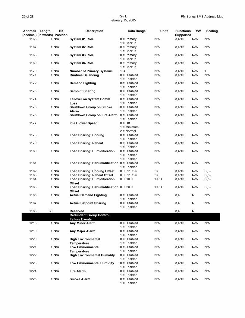
Address Length Bit Description Data Range Units Functions R/W Scaling(decimal) (in words) Position Supported
1166 1 N/A System #1 Role 0 = Primary1 = Backup
N/A 3,4/16 R/W N/A
1167 1 N/A System #2 Role 0 = Primary1 = Backup
N/A 3,4/16 R/W N/A
1168 1 N/A System #3 Role 0 = Primary1 = Backup
N/A 3,4/16 R/W N/A
1169 1 N/A System #4 Role 0 = Primary1 = Backup
N/A 3,4/16 R/W N/A
1170 1 N/A Number of Primary Systems 1..4 N/A 3,4/16 R/W 11171 1 N/A Runtime Balancing 0 = Disabled
1 = EnabledN/A 3,4/16 R/W N/A
1172 1 N/A Demand Fighting 0 = Disabled1 = Enabled
N/A 3,4/16 R/W N/A
1173 1 N/A Setpoint Sharing 0 = Disabled1 = Enabled
N/A 3,4/16 R/W N/A
1174 1 N/A Failover on System Comm. Loss
0 = Disabled1 = Enabled
N/A 3,4/16 R/W N/A
1175 1 N/A Shutdown Group on Smoke Alarm
0 = Disabled1 = Enabled
N/A 3,4/16 R/W N/A
1176 1 N/A Shutdown Group on Fire Alarm 0 = Disabled1 = Enabled
N/A 3,4/16 R/W N/A
1177 1 N/A Idle Blower Speed 0 = Off1 = Minimum2 = Normal
N/A 3,4/16 R/W N/A
1178 1 N/A Load Sharing: Cooling 0 = Disabled1 = Enabled
N/A 3,4/16 R/W N/A
1179 1 N/A Load Sharing: Reheat 0 = Disabled1 = Enabled
N/A 3,4/16 R/W N/A
1180 1 N/A Load Sharing: Humidification 0 = Disabled1 = Enabled
N/A 3,4/16 R/W N/A
1 = Enabled1181 1 N/A Load Sharing: Dehumidification 0 = Disabled
1 = EnabledN/A 3,4/16 R/W N/A
1182 1 N/A Load Sharing: Cooling Offset 0.0.. 11.125 °C 3,4/16 R/W S(5)1183 1 N/A Load Sharing: Reheat Offset 0.0.. 11.125 °C 3,4/16 R/W S(5)1184 1 N/A Load Sharing: Humidification
Offset0.0..10.0 %RH 3,4/16 R/W S(5)
1185 1 N/A Load Sharing: Dehumidification Offset
0.0..20.0 %RH 3,4/16 R/W S(5)
1186 1 N/A Actual Demand Fighting 0 = Disabled1 = Enabled
N/A 3,4 R N/A
1187 1 N/A Actual Setpoint Sharing 0 = Disabled1 = Enabled
N/A 3,4 R N/A
1188 30 Reserved 3,4 RRedundant Group Control Failure Events
1218 1 N/A Any Minor Alarm 0 = Disabled1 = Enabled
N/A 3,4/16 R/W N/A
1219 1 N/A Any Major Alarm 0 = Disabled1 = Enabled
N/A 3,4/16 R/W N/A
1220 1 N/A High Environmental Temperature
0 = Disabled1 = Enabled
N/A 3,4/16 R/W N/A
1221 1 N/A Low Environmental Temperature
0 = Disabled1 = Enabled
N/A 3,4/16 R/W N/A
1222 1 N/A High Environmental Humidity 0 = Disabled1 = Enabled
N/A 3,4/16 R/W N/A
1223 1 N/A Low Environmental Humidity 0 = Disabled1 = Enabled
N/A 3,4/16 R/W N/A
1224 1 N/A Fire Alarm 0 = Disabled1 = Enabled
N/A 3,4/16 R/W N/A
1225 1 N/A Smoke Alarm 0 = Disabled1 = Enabled
N/A 3,4/16 R/W N/A
21 of 28 Rev LFebruary 15, 2005
FM Series BMS Address Map
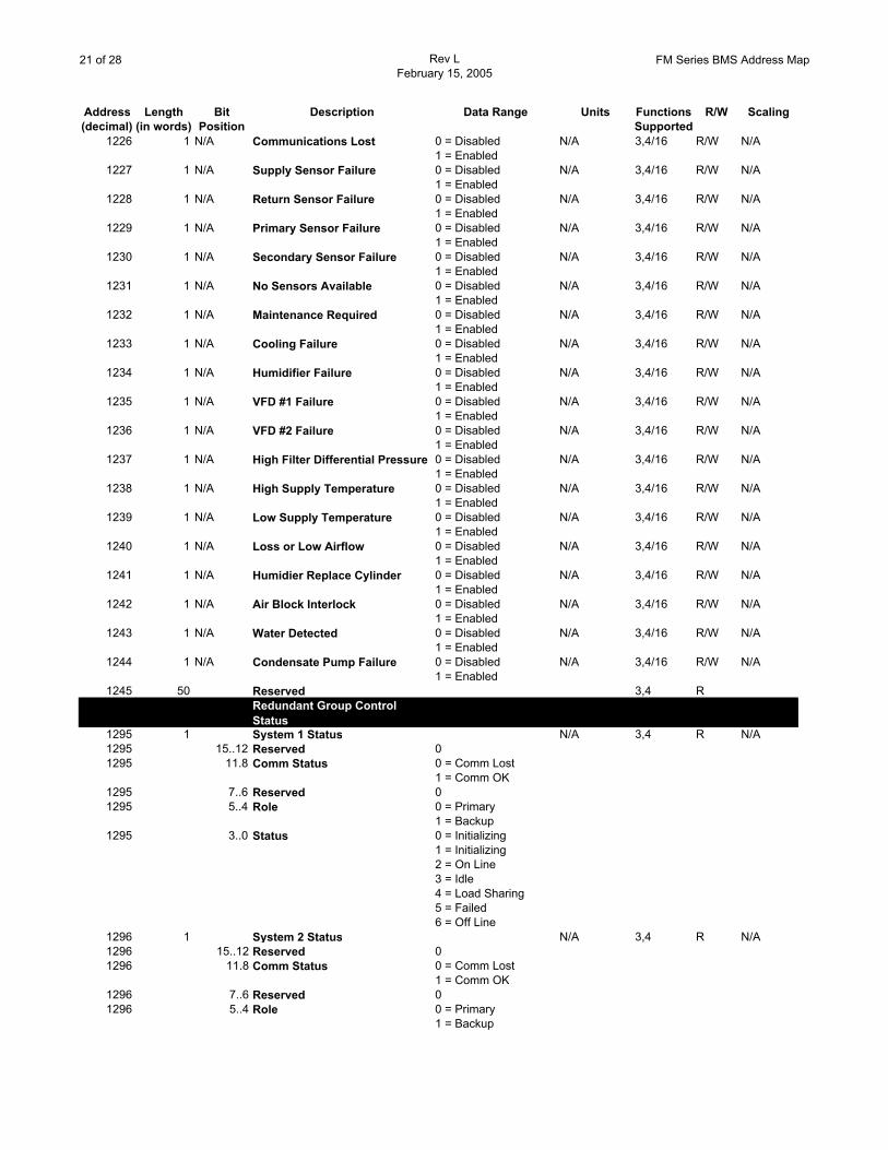
Address Length Bit Description Data Range Units Functions R/W Scaling(decimal) (in words) Position Supported
1226 1 N/A Communications Lost 0 = Disabled1 = Enabled
N/A 3,4/16 R/W N/A
1227 1 N/A Supply Sensor Failure 0 = Disabled1 = Enabled
N/A 3,4/16 R/W N/A
1228 1 N/A Return Sensor Failure 0 = Disabled1 = Enabled
N/A 3,4/16 R/W N/A
1229 1 N/A Primary Sensor Failure 0 = Disabled1 = Enabled
N/A 3,4/16 R/W N/A
1230 1 N/A Secondary Sensor Failure 0 = Disabled1 = Enabled
N/A 3,4/16 R/W N/A
1231 1 N/A No Sensors Available 0 = Disabled1 = Enabled
N/A 3,4/16 R/W N/A
1232 1 N/A Maintenance Required 0 = Disabled1 = Enabled
N/A 3,4/16 R/W N/A
1233 1 N/A Cooling Failure 0 = Disabled1 = Enabled
N/A 3,4/16 R/W N/A
1234 1 N/A Humidifier Failure 0 = Disabled1 = Enabled
N/A 3,4/16 R/W N/A
1235 1 N/A VFD #1 Failure 0 = Disabled1 = Enabled
N/A 3,4/16 R/W N/A
1236 1 N/A VFD #2 Failure 0 = Disabled1 = Enabled
N/A 3,4/16 R/W N/A
1237 1 N/A High Filter Differential Pressure 0 = Disabled1 = Enabled
N/A 3,4/16 R/W N/A
1238 1 N/A High Supply Temperature 0 = Disabled1 = Enabled
N/A 3,4/16 R/W N/A
1239 1 N/A Low Supply Temperature 0 = Disabled1 = Enabled
N/A 3,4/16 R/W N/A
1240 1 N/A Loss or Low Airflow 0 = Disabled1 = Enabled
N/A 3,4/16 R/W N/A
1241 1 N/A Humidier Replace Cylinder 0 = Disabled1 = Enabled
N/A 3,4/16 R/W N/A
1242 1 N/A Air Block Interlock 0 = Disabled1 = Enabled
N/A 3,4/16 R/W N/A
1243 1 N/A Water Detected 0 = Disabled1 = Enabled
N/A 3,4/16 R/W N/A
1244 1 N/A Condensate Pump Failure 0 = Disabled1 = Enabled
N/A 3,4/16 R/W N/A
1245 50 Reserved 3,4 RRedundant Group Control Status
1295 1 System 1 Status N/A 3,4 R N/A1295 15..12 Reserved 01295 11.8 Comm Status 0 = Comm Lost
1 = Comm OK1295 7..6 Reserved 01295 5..4 Role 0 = Primary
1 = Backup1295 3..0 Status 0 = Initializing
1 = Initializing2 = On Line3 = Idle4 = Load Sharing5 = Failed6 = Off Line
1296 1 System 2 Status N/A 3,4 R N/A1296 15..12 Reserved 01296 11.8 Comm Status 0 = Comm Lost
1 = Comm OK1296 7..6 Reserved 01296 5..4 Role 0 = Primary
1 = Backup
22 of 28 Rev LFebruary 15, 2005
FM Series BMS Address Map
Address Length Bit Description Data Range Units Functions R/W Scaling(decimal) (in words) Position Supported
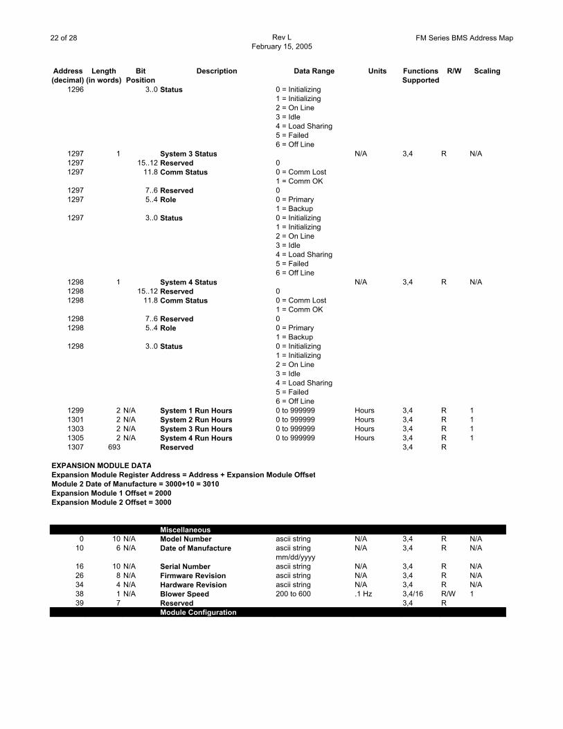
1296 3..0 Status 0 = Initializing1 = Initializing2 = On Line3 = Idle4 = Load Sharing5 = Failed6 = Off Line
1297 1 System 3 Status N/A 3,4 R N/A1297 15..12 Reserved 01297 11.8 Comm Status 0 = Comm Lost
1 = Comm OK1297 7..6 Reserved 01297 5..4 Role 0 = Primary
1 = Backup1297 3..0 Status 0 = Initializing
1 = Initializing2 = On Line3 = Idle4 = Load Sharing5 = Failed6 = Off Line
1298 1 System 4 Status N/A 3,4 R N/A1298 15..12 Reserved 01298 11.8 Comm Status 0 = Comm Lost
1 = Comm OK1298 7..6 Reserved 01298 5..4 Role 0 = Primary
1 = Backup1298 3..0 Status 0 = Initializing
1 = Initializing2 = On Line3 = Idle4 = Load Sharing5 = Failed6 = Off Line
1299 2 N/A System 1 Run Hours 0 to 999999 Hours 3,4 R 11301 2 N/A System 2 Run Hours 0 to 999999 Hours 3,4 R 11303 2 N/A System 3 Run Hours 0 to 999999 Hours 3,4 R 11305 2 N/A System 4 Run Hours 0 to 999999 Hours 3,4 R 11307 693 Reserved 3,4 R
EXPANSION MODULE DATAExpansion Module Register Address = Address + Expansion Module OffsetModule 2 Date of Manufacture = 3000+10 = 3010Expansion Module 1 Offset = 2000Expansion Module 2 Offset = 3000
Miscellaneous0 10 N/A Model Number ascii string N/A 3,4 R N/A
10 6 N/A Date of Manufacture ascii string mm/dd/yyyy
N/A 3,4 R N/A
16 10 N/A Serial Number ascii string N/A 3,4 R N/A26 8 N/A Firmware Revision ascii string N/A 3,4 R N/A34 4 N/A Hardware Revision ascii string N/A 3,4 R N/A38 1 N/A Blower Speed 200 to 600 .1 Hz 3,4/16 R/W 139 7 Reserved 3,4 R
Module Configuration
23 of 28 Rev LFebruary 15, 2005
FM Series BMS Address Map
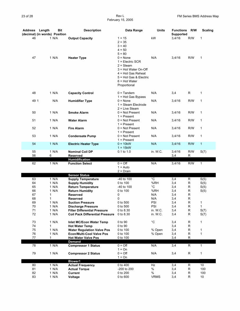
Address Length Bit Description Data Range Units Functions R/W Scaling(decimal) (in words) Position Supported
46 1 N/A Output Capacity 1 = 152 = 353 = 404 = 505 = 80
kW 3,4/16 R/W 1
47 1 N/A Heater Type 0 = None1 = Electric SCR2 = Steam3 = Hot Water On-Off4 = Hot Gas Reheat5 = Hot Gas & Electric6 = Hot Water Proportional
N/A 3,4/16 R/W 1
48 1 N/A Capacity Control 0 = Tandem1 = Hot Gas Bypass
N/A 3,4 R 1
49 1 N/A Humidifier Type 0 = None1 = Steam Electrode2 = Live Steam
N/A 3,4/16 R/W 1
50 1 N/A Smoke Alarm 0 = Not Present1 = Present
N/A 3,4/16 R/W 1
51 1 N/A Water Alarm 0 = Not Present1 = Present
N/A 3,4/16 R/W 1
52 1 N/A Fire Alarm 0 = Not Present1 = Present
N/A 3,4/16 R/W 1
53 1 N/A Condensate Pump 0 = Not Present1 = Present
N/A 3,4/16 R/W 1
54 1 N/A Electric Heater Type 0 = 10kW1 = 15kW
N/A 3,4/16 R/W 1
55 1 N/A Nominal Coil DP 0.1 to 1.0 in. W.C. 3,4/16 R/W S(7)56 6 Reserved 3,4 R
Humidification62 1 N/A Function Select 0 = Off
1 = Auto2 = Drain
N/A 3,4/16 R/W 1
Sensor Status63 1 N/A Supply Temperature -40 to 100 °C 3,4 R S(5)64 1 N/A Supply Humidity 0 to 100 %RH 3,4 R S(5)65 1 N/A Return Temperature -40 to 100 °C 3,4 R S(5)66 1 N/A Return Humidity 0 to 100 %RH 3,4 R S(5)67 1 Reserved 0 N/A 3,4 R68 1 Reserved 0 N/A 3,4 R69 1 N/A Suction Pressure 0 to 500 PSI 3,4 R 170 1 N/A Discharge Pressure 0 to 500 PSI 3,4 R 171 1 N/A Filter Differential Pressure 0 to 8.30 in. W.C. 3,4 R S(7)72 1 N/A Coil Pack Differential Pressure 0 to 8.30 in. W.C. 3,4 R S(7)
73 1 N/A Inlet MC/Econ Water Temp 0 to 90 °C 3,4 R 174 1 Hot Water Temp 0 to 90 3,4 R75 1 N/A Water Regulation Valve Pos 0 to 100 % Open 3,4 R 176 1 N/A Econ/Multi-Cool Valve Pos 0 to 100 % Open 3,4 R 177 1 Hot Water Valve Pos 0 to 100 3,4 R
Demand78 1 N/A Compressor 1 Status 0 = Off
1 = OnN/A 3,4 R 1
79 1 N/A Compressor 2 Status 0 = Off1 = On
N/A 3,4 R 1
Blower180 1 N/A Actual Frequency 0 to 400 Hz 3,4 R 1081 1 N/A Actual Torque -200 to 200 % 3,4 R 10082 1 N/A Current 0 to 200 % 3,4 R 10083 1 N/A Voltage 0 to 600 VRMS 3,4 R 10
24 of 28 Rev LFebruary 15, 2005
FM Series BMS Address Map
Address Length Bit Description Data Range Units Functions R/W Scaling(decimal) (in words) Position Supported
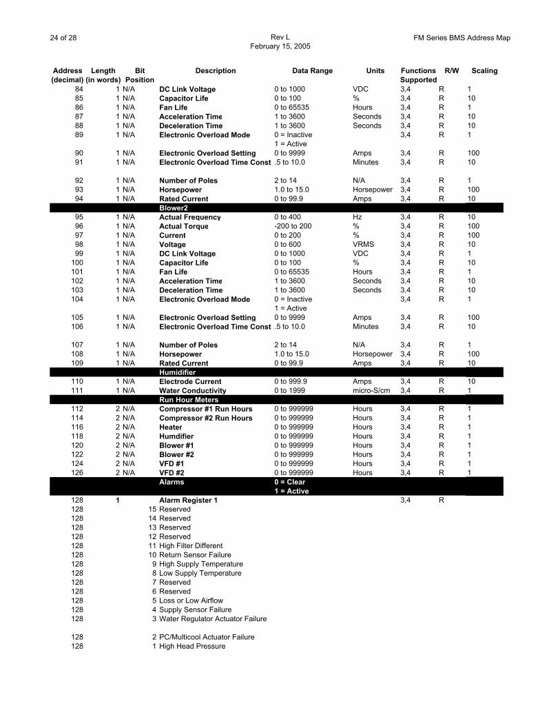
84 1 N/A DC Link Voltage 0 to 1000 VDC 3,4 R 185 1 N/A Capacitor Life 0 to 100 % 3,4 R 1086 1 N/A Fan Life 0 to 65535 Hours 3,4 R 187 1 N/A Acceleration Time 1 to 3600 Seconds 3,4 R 1088 1 N/A Deceleration Time 1 to 3600 Seconds 3,4 R 1089 1 N/A Electronic Overload Mode 0 = Inactive
1 = Active3,4 R 1
90 1 N/A Electronic Overload Setting 0 to 9999 Amps 3,4 R 10091 1 N/A Electronic Overload Time Const .5 to 10.0 Minutes 3,4 R 10
92 1 N/A Number of Poles 2 to 14 N/A 3,4 R 193 1 N/A Horsepower 1.0 to 15.0 Horsepower 3,4 R 10094 1 N/A Rated Current 0 to 99.9 Amps 3,4 R 10
Blower295 1 N/A Actual Frequency 0 to 400 Hz 3,4 R 1096 1 N/A Actual Torque -200 to 200 % 3,4 R 10097 1 N/A Current 0 to 200 % 3,4 R 10098 1 N/A Voltage 0 to 600 VRMS 3,4 R 1099 1 N/A DC Link Voltage 0 to 1000 VDC 3,4 R 1
100 1 N/A Capacitor Life 0 to 100 % 3,4 R 10101 1 N/A Fan Life 0 to 65535 Hours 3,4 R 1102 1 N/A Acceleration Time 1 to 3600 Seconds 3,4 R 10103 1 N/A Deceleration Time 1 to 3600 Seconds 3,4 R 10104 1 N/A Electronic Overload Mode 0 = Inactive
1 = Active3,4 R 1
105 1 N/A Electronic Overload Setting 0 to 9999 Amps 3,4 R 100106 1 N/A Electronic Overload Time Const .5 to 10.0 Minutes 3,4 R 10
107 1 N/A Number of Poles 2 to 14 N/A 3,4 R 1108 1 N/A Horsepower 1.0 to 15.0 Horsepower 3,4 R 100109 1 N/A Rated Current 0 to 99.9 Amps 3,4 R 10
Humidifier110 1 N/A Electrode Current 0 to 999.9 Amps 3,4 R 10111 1 N/A Water Conductivity 0 to 1999 micro-S/cm 3,4 R 1
Run Hour Meters112 2 N/A Compressor #1 Run Hours 0 to 999999 Hours 3,4 R 1114 2 N/A Compressor #2 Run Hours 0 to 999999 Hours 3,4 R 1116 2 N/A Heater 0 to 999999 Hours 3,4 R 1118 2 N/A Humdifier 0 to 999999 Hours 3,4 R 1120 2 N/A Blower #1 0 to 999999 Hours 3,4 R 1122 2 N/A Blower #2 0 to 999999 Hours 3,4 R 1124 2 N/A VFD #1 0 to 999999 Hours 3,4 R 1126 2 N/A VFD #2 0 to 999999 Hours 3,4 R 1
Alarms 0 = Clear1 = Active
128 1 Alarm Register 1 3,4 R128 15 Reserved128 14 Reserved128 13 Reserved128 12 Reserved128 11 High Filter Different128 10 Return Sensor Failure128 9 High Supply Temperature128 8 Low Supply Temperature128 7 Reserved128 6 Reserved128 5 Loss or Low Airflow128 4 Supply Sensor Failure128 3 Water Regulator Actuator Failure
128 2 PC/Multicool Actuator Failure128 1 High Head Pressure
25 of 28 Rev LFebruary 15, 2005
FM Series BMS Address Map
Address Length Bit Description Data Range Units Functions R/W Scaling(decimal) (in words) Position Supported
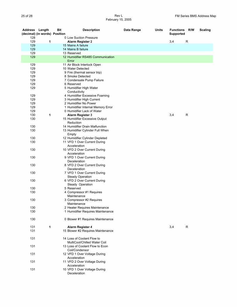
128 0 Low Suction Pressure129 1 Alarm Register 2 3,4 R129 15 Mains A failure129 14 Mains B failure129 13 Reserved129 12 Humidifier RS485 Communication
Error129 11 Air Block Interlock Open129 10 Water Detected129 9 Fire (thermal sensor trip)129 8 Smoke Detected129 7 Condensate Pump Failure129 6 Reserved129 5 Humidifier High Water
Conductivity129 4 Humidifier Excessive Foaming129 3 Humidifier High Current129 2 Humidifier No Power129 1 Humidifier Internal Memory Error129 0 Humidifier Lack of Water130 1 Alarm Register 3 3,4 R130 15 Humidifier Excessive Output
Reduction130 14 Humidifier Drain Malfunction130 13 Humidifier Cylinder Full When
Empty130 12 Humidifier Cylinder Depleted130 11 VFD 1 Over Current During
Acceleration130 10 VFD 2 Over Current During
Acceleration130 9 VFD 1 Over Current During
Deceleration130 8 VFD 2 Over Current During
Deceleration130 7 VFD 1 Over Current During
Steady Operation130 6 VFD 2 Over Current During
Steady Operation130 5 Reserved130 4 Compressor #1 Requires
Maintenance130 3 Compressor #2 Requires
Maintenance130 2 Heater Requires Maintenance130 1 Humidifier Requires Maintenance
130 0 Blower #1 Requires Maintenance
131 1 Alarm Register 4 3,4 R131 15 Blower #2 Requires Maintenance
131 14 Loss of Coolant Flow to MultiCool/Chilled Water Coil
131 13 Loss of Coolant Flow to Econ Coil/Condensor
131 12 VFD 1 Over Voltage During Acceleration
131 11 VFD 2 Over Voltage During Acceleration
131 10 VFD 1 Over Voltage During Deceleration
26 of 28 Rev LFebruary 15, 2005
FM Series BMS Address Map
Address Length Bit Description Data Range Units Functions R/W Scaling(decimal) (in words) Position Supported
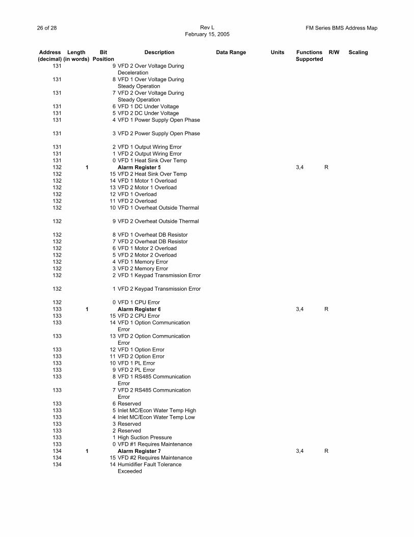
131 9 VFD 2 Over Voltage During Deceleration
131 8 VFD 1 Over Voltage During Steady Operation
131 7 VFD 2 Over Voltage During Steady Operation
131 6 VFD 1 DC Under Voltage131 5 VFD 2 DC Under Voltage131 4 VFD 1 Power Supply Open Phase
131 3 VFD 2 Power Supply Open Phase
131 2 VFD 1 Output Wiring Error131 1 VFD 2 Output Wiring Error131 0 VFD 1 Heat Sink Over Temp132 1 Alarm Register 5 3,4 R132 15 VFD 2 Heat Sink Over Temp132 14 VFD 1 Motor 1 Overload132 13 VFD 2 Motor 1 Overload132 12 VFD 1 Overload132 11 VFD 2 Overload132 10 VFD 1 Overheat Outside Thermal
132 9 VFD 2 Overheat Outside Thermal
132 8 VFD 1 Overheat DB Resistor132 7 VFD 2 Overheat DB Resistor132 6 VFD 1 Motor 2 Overload132 5 VFD 2 Motor 2 Overload132 4 VFD 1 Memory Error132 3 VFD 2 Memory Error132 2 VFD 1 Keypad Transmission Error
132 1 VFD 2 Keypad Transmission Error
132 0 VFD 1 CPU Error133 1 Alarm Register 6 3,4 R133 15 VFD 2 CPU Error133 14 VFD 1 Option Communication
Error133 13 VFD 2 Option Communication
Error133 12 VFD 1 Option Error133 11 VFD 2 Option Error133 10 VFD 1 PL Error133 9 VFD 2 PL Error133 8 VFD 1 RS485 Communication
Error133 7 VFD 2 RS485 Communication
Error133 6 Reserved133 5 Inlet MC/Econ Water Temp High133 4 Inlet MC/Econ Water Temp Low133 3 Reserved133 2 Reserved133 1 High Suction Pressure133 0 VFD #1 Requires Maintenance134 1 Alarm Register 7 3,4 R134 15 VFD #2 Requires Maintenance134 14 Humidifier Fault Tolerance
Exceeded
27 of 28 Rev LFebruary 15, 2005
FM Series BMS Address Map
Address Length Bit Description Data Range Units Functions R/W Scaling(decimal) (in words) Position Supported
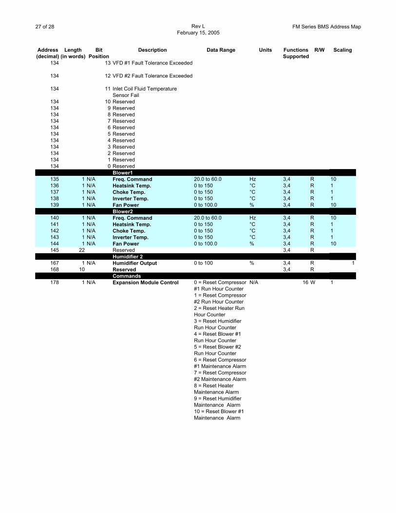
134 13 VFD #1 Fault Tolerance Exceeded
134 12 VFD #2 Fault Tolerance Exceeded
134 11 Inlet Coil Fluid Temperature Sensor Fail
134 10 Reserved134 9 Reserved134 8 Reserved134 7 Reserved134 6 Reserved134 5 Reserved134 4 Reserved134 3 Reserved134 2 Reserved134 1 Reserved134 0 Reserved
Blower1135 1 N/A Freq. Command 20.0 to 60.0 Hz 3,4 R 10136 1 N/A Heatsink Temp. 0 to 150 °C 3,4 R 1137 1 N/A Choke Temp. 0 to 150 °C 3,4 R 1138 1 N/A Inverter Temp. 0 to 150 °C 3,4 R 1139 1 N/A Fan Power 0 to 100.0 % 3,4 R 10
Blower2140 1 N/A Freq. Command 20.0 to 60.0 Hz 3,4 R 10141 1 N/A Heatsink Temp. 0 to 150 °C 3,4 R 1142 1 N/A Choke Temp. 0 to 150 °C 3,4 R 1143 1 N/A Inverter Temp. 0 to 150 °C 3,4 R 1144 1 N/A Fan Power 0 to 100.0 % 3,4 R 10145 22 Reserved 3,4 R
Humidifier 2167 1 N/A Humidifier Output 0 to 100 % 3,4 R 1168 10 Reserved 3,4 R
Commands178 1 N/A Expansion Module Control 0 = Reset Compressor
#1 Run Hour Counter1 = Reset Compressor #2 Run Hour Counter2 = Reset Heater Run Hour Counter3 = Reset Humidifier Run Hour Counter4 = Reset Blower #1 Run Hour Counter5 = Reset Blower #2 Run Hour Counter6 = Reset Compressor #1 Maintenance Alarm7 = Reset Compressor #2 Maintenance Alarm8 = Reset Heater Maintenance Alarm9 = Reset Humidifier Maintenance Alarm10 = Reset Blower #1 Maintenance Alarm
N/A 16 W 1
28 of 28 Rev LFebruary 15, 2005
FM Series BMS Address Map
Address Length Bit Description Data Range Units Functions R/W Scaling(decimal) (in words) Position Supported
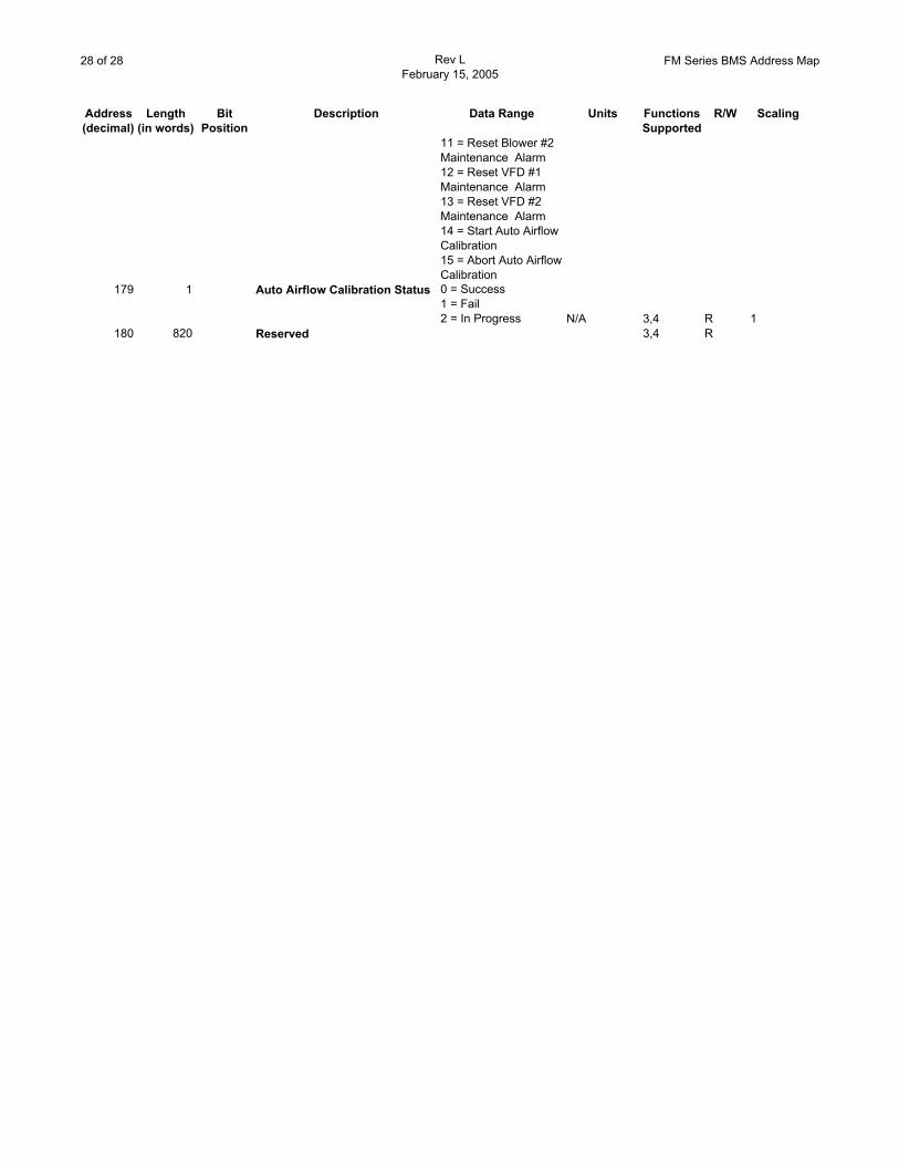
11 = Reset Blower #2 Maintenance Alarm12 = Reset VFD #1 Maintenance Alarm13 = Reset VFD #2 Maintenance Alarm14 = Start Auto Airflow Calibration15 = Abort Auto Airflow Calibration
179 1 Auto Airflow Calibration Status 0 = Success1 = Fail2 = In Progress N/A 3,4 R 1
180 820 Reserved 3,4 R