Embed Size (px)
Citation preview
1
WARNINGImproper installation, adjustment, alteration, service or maintenance can cause property damage, personal injury or loss of life. Installation and service must be performed by a qualified installer, service agency or the gas supplier
CAUTIONDanger of sharp metallic edges. Can cause injury.Take care when servicing unit to avoid accidental contact with sharp edges.
INSTALLATION INSTRUCTIONS FOR ECONOMIZERS USED WITH ZC,ZG,ZH 036,048,060 UNITS
Z1ECON16 (98W68) ECONOMIZERSHORIZONTAL ECONOMIZERS
!
!
Package 1 of 1 contains: 1 - Economizer damper assembly 1 - Outdoor air damper 1 - Return air damper 1 - Gravity exhaust damper 1 - Return Air Cover 1 - Economizer actuator 1 - Economizer control module 1 - Outdoor air temperature sensor 1 - Hardware bag 1 - Mixed air sensor 3 - #10-14 x 3/4” screws with washer 11 - #10-16 x 5/8” screws 1 - Side economizer panel 1 - Bottom return air cover panelOrder Of Installation Bottom return air cover Economizer Mixed air sensor Optional OA and RA sensors Power Exhaust fans (optional) Side economizer panel
Shipping and Packing List
ApplicationThe Z1ECON16 (98W68) economizer is used with ZC,ZG,ZH 036,048,060 units in horizontal air discharge applications. Economizer dampers will modulate to maintain 55oF (13oC) supply air when outdoor air is suitable. The mixed air temperature sensor measures the supply air sensible temperature.An outdoor air sensor is used to determine whether outdoor air is suitable for free cooling. The outdoor air sensor is factory-installed in all economizers. Other outdoor and return air (OA and RA) sensor options are available to determine whether outdoor air is suitable for free cooling. See Table 1 and the instructions provided with optional senors.
INDOOR AIR QUALITY SENSORAn IAQ sensor is used when demand control ventilation (DCV) is specified. Damper minimum position can be set lower than traditional minimum air requirements resulting in cost savings. The IAQ sensor allows the economizer control module to open dampers to traditional ventilation requirements as room occupancy (CO2) increases.For proper operation, the IAQ sensor must provide a 2-10VDC, 100 ohm impedance signal. Connect sensor leads to AQ and AQ1 terminals on the economizer control module located in the filter section.
TABLE 1
Sensors Dampers modulate to maintain55oF mixed air (R1) when:
*Single OA Sensible OA temperature is lowerthan free cooling setpoint
Single OA Enthalpy OA temperature and humidity is suitable for free cooling
Differential Enthalpy- 1 in OA & 1 in RA
OA temperature and humidity is lower than RA temperature and
humidity.
Figure 1
*Single OA sensible sensor is shipped standard on economizer
2
Figure 2
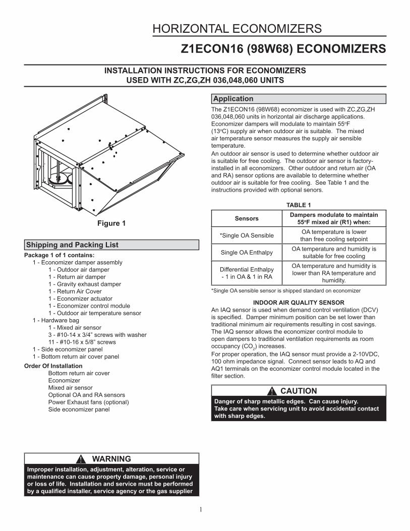
Install Economizer1. Disconnect all power sources to the unit2. Remove the following panels from the unit; - Filter door panel - Return chamber panel - Indoor fan panel3. Locate return air cover included in kit. Place a bead of
silicone sealant on the underside of the return air cover flanges.
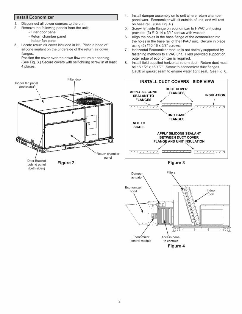
Position the cover over the down flow return air opening. (See Fig. 3.) Secure covers with self-drilling screw in at least 4 places.
4. Install damper assembly on to unit where return chamber panel was. Economizer will sit outside of unit, and will rest on base rail. (See Fig. 4.)
5. Screw left side flange on economizer to HVAC unit using provided (3) #10-14 x 3/4” screws with washer.
6. Align the holes in the base flange of the economizer into the holes in the base rail of the HVAC unit. Secure in place using (5) #10-16 x 5/8” screws.
7. Horizontal Economizer module is not entirely supported by fastening methods to HVAC unit. Field provided support on outer edge of economizer is required.
8. Install field supplied horizontal return duct. Return duct must be 16 1/2” x 16 1/2”. Screw to economizer duct flanges. Caulk or gasket seam to ensure water tight seal. See Fig. 6.
Indoor fan panel(backside)
Filter door
Return chamber panel
Door Bracketbehind panel(both sides)
Figure 4
Figure 3
Economizerhood
Damperactuator
Filters
Indoorcoil
Economizercontrol module
Access panelto controls
INSTALL DUCT COVERS - SIDE VIEW
APPLY SILICONESEALANT TO
FLANGES
DUCT COVERFLANGES INSULATION
UNIT BASEFLANGES
NOT TOSCALE
APPLY SILICONE SEALANTBETWEEN DUCT COVER
FLANGE AND UNIT INSULATION
3
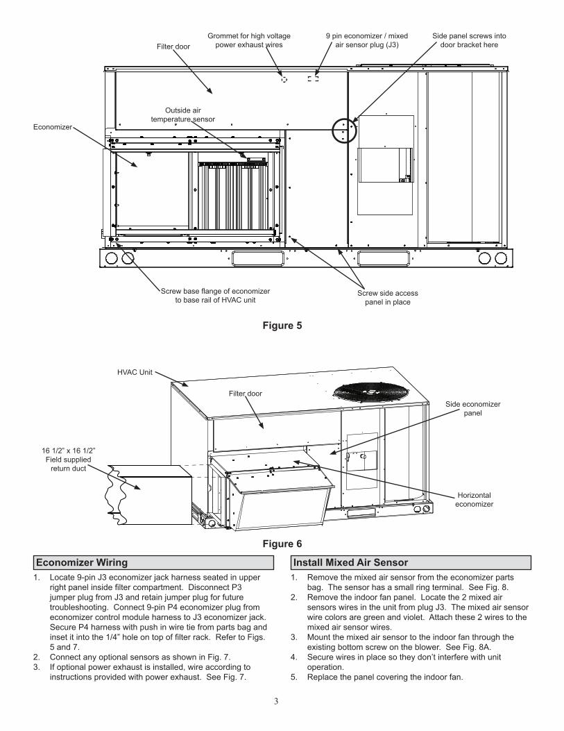
Install Mixed Air Sensor 1. Remove the mixed air sensor from the economizer parts
bag. The sensor has a small ring terminal. See Fig. 8.2. Remove the indoor fan panel. Locate the 2 mixed air
sensors wires in the unit from plug J3. The mixed air sensor wire colors are green and violet. Attach these 2 wires to the mixed air sensor wires.
3. Mount the mixed air sensor to the indoor fan through the existing bottom screw on the blower. See Fig. 8A.
4. Secure wires in place so they don’t interfere with unit operation.
5. Replace the panel covering the indoor fan.
Economizer Wiring1. Locate 9-pin J3 economizer jack harness seated in upper
right panel inside filter compartment. Disconnect P3 jumper plug from J3 and retain jumper plug for future troubleshooting. Connect 9-pin P4 economizer plug from economizer control module harness to J3 economizer jack. Secure P4 harness with push in wire tie from parts bag and inset it into the 1/4” hole on top of filter rack. Refer to Figs. 5 and 7.
2. Connect any optional sensors as shown in Fig. 7.3. If optional power exhaust is installed, wire according to
instructions provided with power exhaust. See Fig. 7.
Filter doorSide panel screws into
door bracket here9 pin economizer / mixed
air sensor plug (J3)Grommet for high voltage
power exhaust wires
Outside air temperature sensor
Screw side access panel in place
Screw base flange of economizer to base rail of HVAC unit
Economizer
Figure 5
Figure 6
16 1/2” x 16 1/2”Field supplied
return duct
HVAC Unit
Filter doorSide economizer
panel
Horizontaleconomizer
4
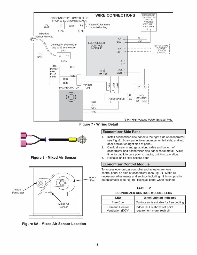
Economizer Side Panel
Economizer Control Module
1. Install economizer side panel to the right side of economizer, see Fig. 6. Screw panel to economizer on left side, and into door bracket on right side of panel.
2. Caulk all seams and gaps along sides and bottom of economizer and economizer side panel sheet metal. Allow time for caulk to cure prior to placing unit into operation.
3. Reinstall unit’s filter access door.
To access economizer controller and actuator, remove control panel on side of economizer (see Fig. 4). Make all necessary adjustments and settings including minimum position potentiometer (see Fig. 9). Reinstall panel when finished.
TABLE 2ECONOMIZER CONTROL MODULE LEDsLED When Lighted Indicates
Free Cool Outdoor air is suitable for free coolingDemand ControlVentilation (DCV)
Indoor IAQ is above set point requirement more fresh air
Figure 8A - Mixed Air Sensor Location
IndoorFan Motor
Mixed AirSensor
Indoor Fan
Figure 8 - Mixed Air Sensor
Figure 7 - Wiring Detail
DISCONNECT P3 JUMPER PLUGFROM J3 ECONOMIZER JACK
J3 P3TOUNIT
J3TOUNIT P4
ECONOMIZERCONTROLMODULE
RED
RED
BRNJ18
GR
N
GR
YW
HT
BLK
BLK
BLUVIO
GRY
*PLUGJ24
PNK
DAMPER MOTOR
BLU
8
IAQSENSOR(OPTION)
7
J9
P9
Retain P3 for futuretroubleshooting.
DIFFERENTIAL ENTHALPYSENSOR(OPTION)
SRSR+
9−PIN 9−PIN
9−PIN
SO+SO
TT1
EF1 EF AQ1AQ
Actuator plug
*3 Pin High Voltage Power Exhaust Plug
POWER EXHPLUG5-PIN
OUTDOOR AIRTEMPERATURE
SENSORPROVIDED(ENTHALPYOPTIONAL)
Connect P4 economizerplug to J3 economizer
jack
Mixed AirSensor Provided
WIRE CONNECTIONS
5
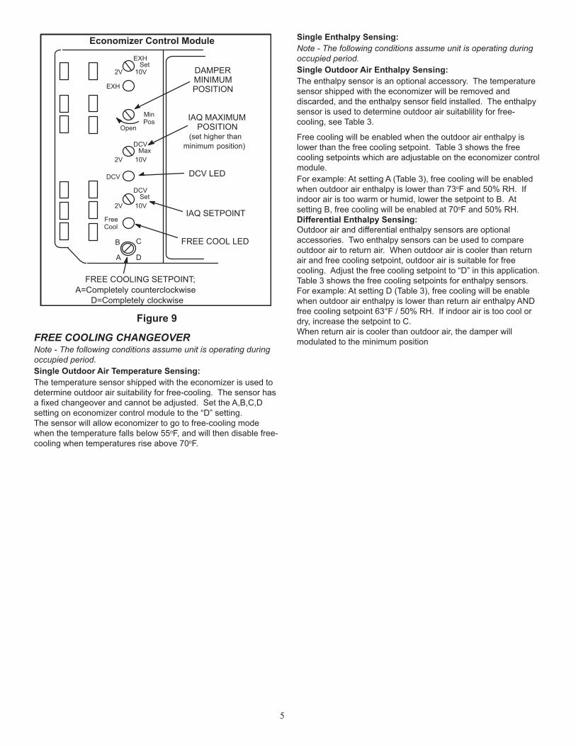
Figure 9
A6 ENTHALPY CONTROL
A
B C
D
Open
MinPos
FREE COOLING SETPOINT;A=Completely counterclockwise
D=Completely clockwise
FREE COOL LED
FreeCool
DCV
EXH
EXHSet
2V 10V
DCVMax
2V 10V
DCVSet
2V 10VIAQ SETPOINT
DCV LED
DAMPERMINIMUMPOSITION
IAQ MAXIMUMPOSITION
(set higher thanminimum position)
FREE COOLING CHANGEOVERNote - The following conditions assume unit is operating during occupied period.Single Outdoor Air Temperature Sensing:The temperature sensor shipped with the economizer is used to determine outdoor air suitability for free-cooling. The sensor has a fixed changeover and cannot be adjusted. Set the A,B,C,D setting on economizer control module to the “D” setting.The sensor will allow economizer to go to free-cooling mode when the temperature falls below 55oF, and will then disable free-cooling when temperatures rise above 70oF.
Free cooling will be enabled when the outdoor air enthalpy is lower than the free cooling setpoint. Table 3 shows the free cooling setpoints which are adjustable on the economizer control module.For example: At setting A (Table 3), free cooling will be enabled when outdoor air enthalpy is lower than 73oF and 50% RH. If indoor air is too warm or humid, lower the setpoint to B. At setting B, free cooling will be enabled at 70oF and 50% RH.Differential Enthalpy Sensing:Outdoor air and differential enthalpy sensors are optional accessories. Two enthalpy sensors can be used to compare outdoor air to return air. When outdoor air is cooler than return air and free cooling setpoint, outdoor air is suitable for free cooling. Adjust the free cooling setpoint to “D” in this application. Table 3 shows the free cooling setpoints for enthalpy sensors.For example: At setting D (Table 3), free cooling will be enable when outdoor air enthalpy is lower than return air enthalpy AND free cooling setpoint 63°F / 50% RH. If indoor air is too cool or dry, increase the setpoint to C.When return air is cooler than outdoor air, the damper will modulated to the minimum position
Economizer Control Module Single Enthalpy Sensing:Note - The following conditions assume unit is operating during occupied period.Single Outdoor Air Enthalpy Sensing:The enthalpy sensor is an optional accessory. The temperature sensor shipped with the economizer will be removed and discarded, and the enthalpy sensor field installed. The enthalpy sensor is used to determine outdoor air suitablility for free-cooling, see Table 3.
6
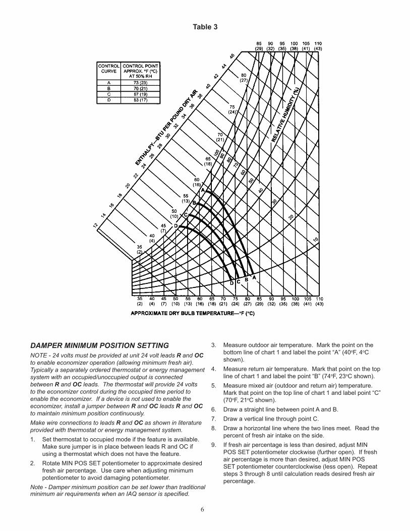
DAMPER MINIMUM POSITION SETTINGNOTE - 24 volts must be provided at unit 24 volt leads R and OC to enable economizer operation (allowing minimum fresh air). Typically a separately ordered thermostat or energy management system with an occupied/unoccupied output is connected between R and OC leads. The thermostat will provide 24 volts to the economizer control during the occupied time period to enable the economizer. If a device is not used to enable the economizer, install a jumper between R and OC leads R and OC to maintain minimum position continuously.Make wire connections to leads R and OC as shown in literature provided with thermostat or energy management system.1. Set thermostat to occupied mode if the feature is available.
Make sure jumper is in place between leads R and OC if using a thermostat which does not have the feature.
2. Rotate MIN POS SET potentiometer to approximate desired fresh air percentage. Use care when adjusting minimum potentiometer to avoid damaging potentiometer.
Note - Damper minimum position can be set lower than traditional minimum air requirements when an IAQ sensor is specified.
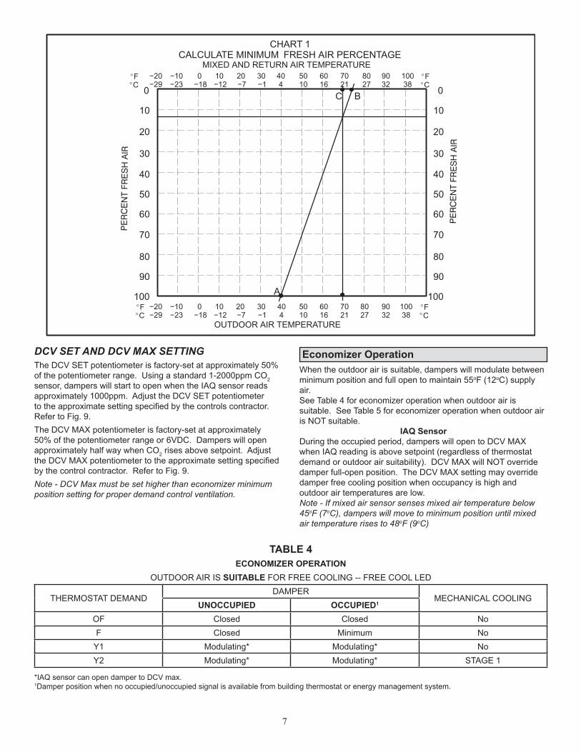
3. Measure outdoor air temperature. Mark the point on the bottom line of chart 1 and label the point “A” (40oF, 4oC shown).
4. Measure return air temperature. Mark that point on the top line of chart 1 and label the point “B” (74oF, 23oC shown).
5. Measure mixed air (outdoor and return air) temperature. Mark that point on the top line of chart 1 and label point “C” (70oF, 21oC shown).
6. Draw a straight line between point A and B.7. Draw a vertical line through point C.8. Draw a horizontal line where the two lines meet. Read the
percent of fresh air intake on the side.9. If fresh air percentage is less than desired, adjust MIN
POS SET potentiometer clockwise (further open). If fresh air percentage is more than desired, adjust MIN POS SET potentiometer counterclockwise (less open). Repeat steps 3 through 8 until calculation reads desired fresh air percentage.
Table 3
7
−20−29
−10−23
0−18
10−12
20−7
30−1
404
5010
6016
7021
8027
9032
10038
0
10
30
40
50
60
70
80
90
100
20
OUTDOOR AIR TEMPERATURE
0
10
30
40
50
60
70
80
90
100
20
MIXED AND RETURN AIR TEMPERATURE
CHART 1CALCULATE MINIMUM FRESH AIR PERCENTAGE
A
BC
FC
FC
−20−29
−10−23
0−18
10−12
20−7
30−1
404
5010
6016
7021
8027
9032
10038
FC
FC
DCV SET AND DCV MAX SETTINGThe DCV SET potentiometer is factory-set at approximately 50% of the potentiometer range. Using a standard 1-2000ppm CO2 sensor, dampers will start to open when the IAQ sensor reads approximately 1000ppm. Adjust the DCV SET potentiometer to the approximate setting specified by the controls contractor. Refer to Fig. 9.The DCV MAX potentiometer is factory-set at approximately 50% of the potentiometer range or 6VDC. Dampers will open approximately half way when CO2 rises above setpoint. Adjust the DCV MAX potentiometer to the approximate setting specified by the control contractor. Refer to Fig. 9.Note - DCV Max must be set higher than economizer minimum position setting for proper demand control ventilation.
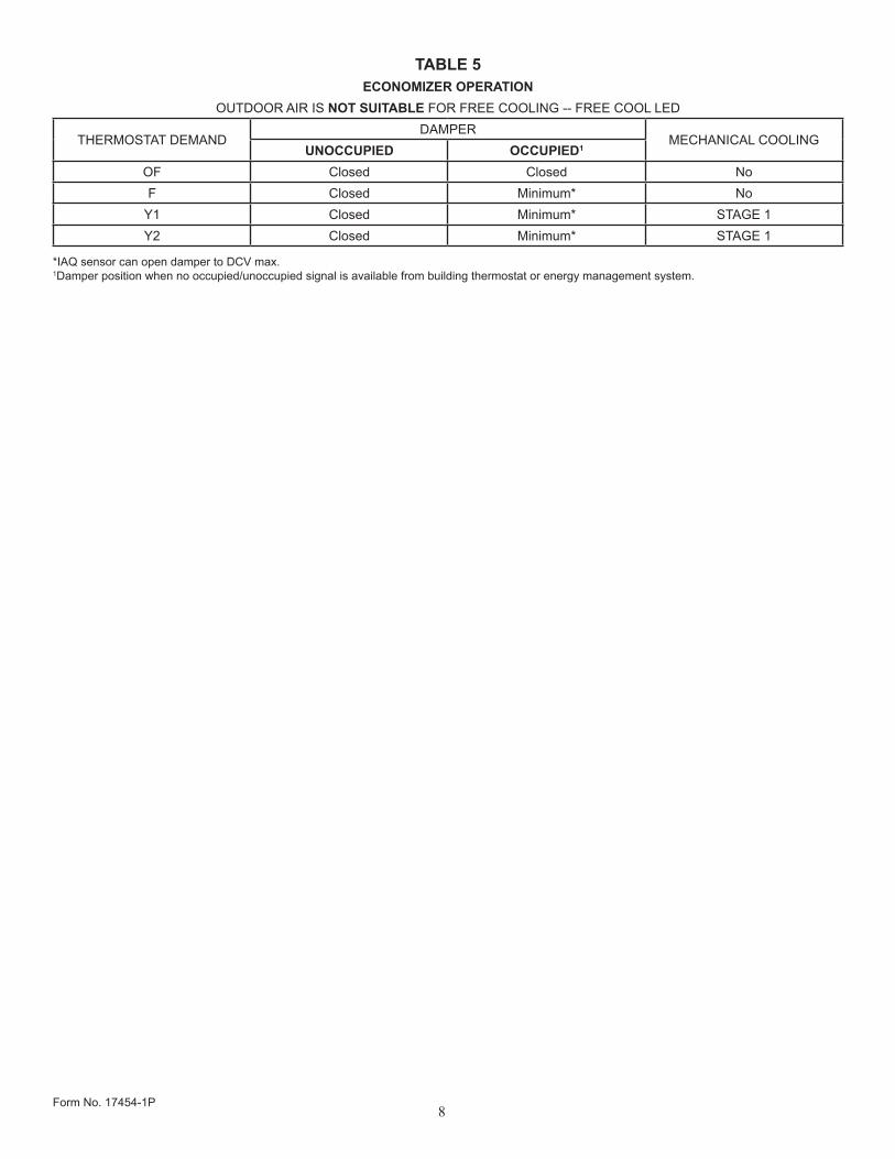
Economizer OperationWhen the outdoor air is suitable, dampers will modulate between minimum position and full open to maintain 55oF (12oC) supply air.See Table 4 for economizer operation when outdoor air is suitable. See Table 5 for economizer operation when outdoor air is NOT suitable.
IAQ SensorDuring the occupied period, dampers will open to DCV MAX when IAQ reading is above setpoint (regardless of thermostat demand or outdoor air suitability). DCV MAX will NOT override damper full-open position. The DCV MAX setting may override damper free cooling position when occupancy is high and outdoor air temperatures are low.Note - If mixed air sensor senses mixed air temperature below 45oF (7oC), dampers will move to minimum position until mixed air temperature rises to 48oF (9oC)
TABLE 4ECONOMIZER OPERATION
OUTDOOR AIR IS SUITABLE FOR FREE COOLING -- FREE COOL LED
THERMOSTAT DEMANDDAMPER
MECHANICAL COOLINGUNOCCUPIED OCCUPIED1
OF Closed Closed NoF Closed Minimum No
Y1 Modulating* Modulating* NoY2 Modulating* Modulating* STAGE 1
*IAQ sensor can open damper to DCV max.1Damper position when no occupied/unoccupied signal is available from building thermostat or energy management system.
8
TABLE 5ECONOMIZER OPERATION
OUTDOOR AIR IS NOT SUITABLE FOR FREE COOLING -- FREE COOL LED
THERMOSTAT DEMANDDAMPER
MECHANICAL COOLINGUNOCCUPIED OCCUPIED1
OF Closed Closed NoF Closed Minimum* No
Y1 Closed Minimum* STAGE 1Y2 Closed Minimum* STAGE 1
*IAQ sensor can open damper to DCV max.1Damper position when no occupied/unoccupied signal is available from building thermostat or energy management system.
Form No. 17454-1P