Embed Size (px)
Citation preview
BRISTOL BABCOCK APPLICATION NOTE
TeleFlow/AATM Page 1
Wiring TeleFlow (3530-XXX)To
Invensys Auto-Adjust Turbo-Meter
Table of Contents
Section 1 - FORWARD ..............................................................................................................2
Section 2 - DEFINITIONS ........................................................................................................2
Section 3 - WIRING...................................................................................................................3
Section 4 - SOFTWARE CONFIGURATION..........................................................................13
BRISTOL BABCOCK APPLICATION NOTE
Page 2 TeleFlow/AATM
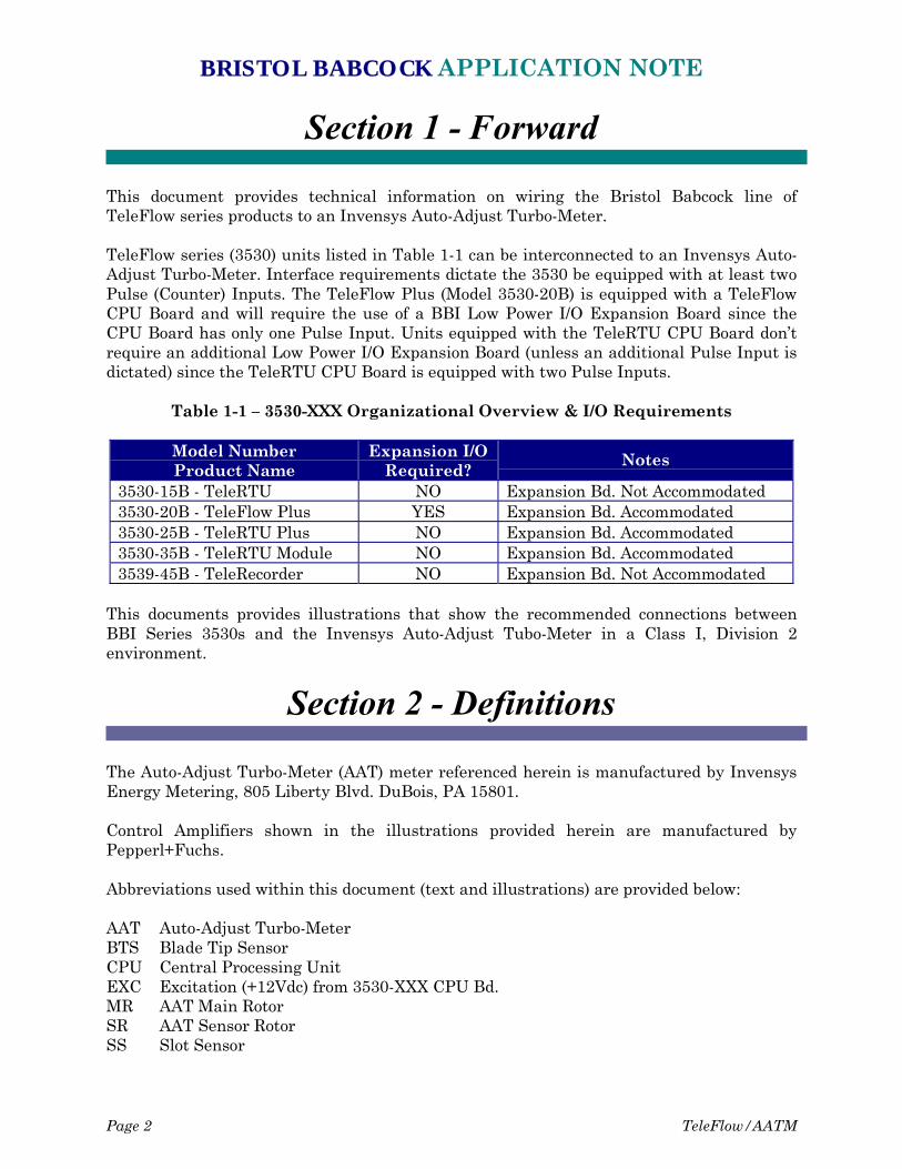
Section 1 - Forward
This document provides technical information on wiring the Bristol Babcock line ofTeleFlow series products to an Invensys Auto-Adjust Turbo-Meter.
TeleFlow series (3530) units listed in Table 1-1 can be interconnected to an Invensys Auto-Adjust Turbo-Meter. Interface requirements dictate the 3530 be equipped with at least twoPulse (Counter) Inputs. The TeleFlow Plus (Model 3530-20B) is equipped with a TeleFlowCPU Board and will require the use of a BBI Low Power I/O Expansion Board since theCPU Board has only one Pulse Input. Units equipped with the TeleRTU CPU Board don’trequire an additional Low Power I/O Expansion Board (unless an additional Pulse Input isdictated) since the TeleRTU CPU Board is equipped with two Pulse Inputs.
Table 1-1 – 3530-XXX Organizational Overview & I/O Requirements
Model NumberProduct Name
Expansion I/ORequired?
Notes
3530-15B - TeleRTU NO Expansion Bd. Not Accommodated3530-20B - TeleFlow Plus YES Expansion Bd. Accommodated3530-25B - TeleRTU Plus NO Expansion Bd. Accommodated3530-35B - TeleRTU Module NO Expansion Bd. Accommodated3539-45B - TeleRecorder NO Expansion Bd. Not Accommodated
This documents provides illustrations that show the recommended connections betweenBBI Series 3530s and the Invensys Auto-Adjust Tubo-Meter in a Class I, Division 2environment.
Section 2 - Definitions
The Auto-Adjust Turbo-Meter (AAT) meter referenced herein is manufactured by InvensysEnergy Metering, 805 Liberty Blvd. DuBois, PA 15801.
Control Amplifiers shown in the illustrations provided herein are manufactured byPepperl+Fuchs.
Abbreviations used within this document (text and illustrations) are provided below:
AAT Auto-Adjust Turbo-MeterBTS Blade Tip SensorCPU Central Processing UnitEXC Excitation (+12Vdc) from 3530-XXX CPU Bd.MR AAT Main RotorSR AAT Sensor RotorSS Slot Sensor
BRISTOL BABCOCK APPLICATION NOTE
TeleFlow/AATM Page 3
Section 3 - Wiring
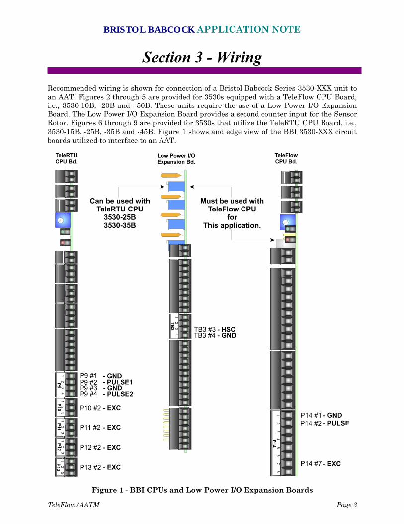
Recommended wiring is shown for connection of a Bristol Babcock Series 3530-XXX unit toan AAT. Figures 2 through 5 are provided for 3530s equipped with a TeleFlow CPU Board,i.e., 3530-10B, -20B and –50B. These units require the use of a Low Power I/O ExpansionBoard. The Low Power I/O Expansion Board provides a second counter input for the SensorRotor. Figures 6 through 9 are provided for 3530s that utilize the TeleRTU CPU Board, i.e.,3530-15B, -25B, -35B and -45B. Figure 1 shows and edge view of the BBI 3530-XXX circuitboards utilized to interface to an AAT.
Figure 1 - BBI CPUs and Low Power I/O Expansion Boards
BRISTOL BABCOCK APPLICATION NOTE
Page 4 TeleFlow/AATM
A control amplifier/barrier is required between the AAT and the 3530-XXX; the amplifiermodel numbers shown (“K” numbers) in Figures 2 through 9 are for Pepprl+Fuchs devices.
Wiring diagrams are provided for the following 4 different types of amplifiers:
24 Vdc with Slot Sensor (SS)24 Vdc with Blade Tip Sensor (BTS)120 Vac with SS120 Vac with BTS
The Blade tip configuration requires +12 VDC to the AAT sensors through a MTL715+isolator made by MTL Instruments Inc.
The amplifier outputs are connected in “emitter-follower” mode i.e., the emitter of theoutput transistor connects to the 3530-XXX counter input which has a 1000 ohm “pulldown” resistor to circuit common.
+12 Vdc for the amplifier output stage is supplied from the 3530-XXX CPU Board via anExcitation (EXC) terminal. On the TeleRTU CPU Board, EXC is available from Pin #2 ofconnectors P10, P11, P12 or P13. On the TeleFlow CPU Board, EXC is available from Pin#7 of connector P14.
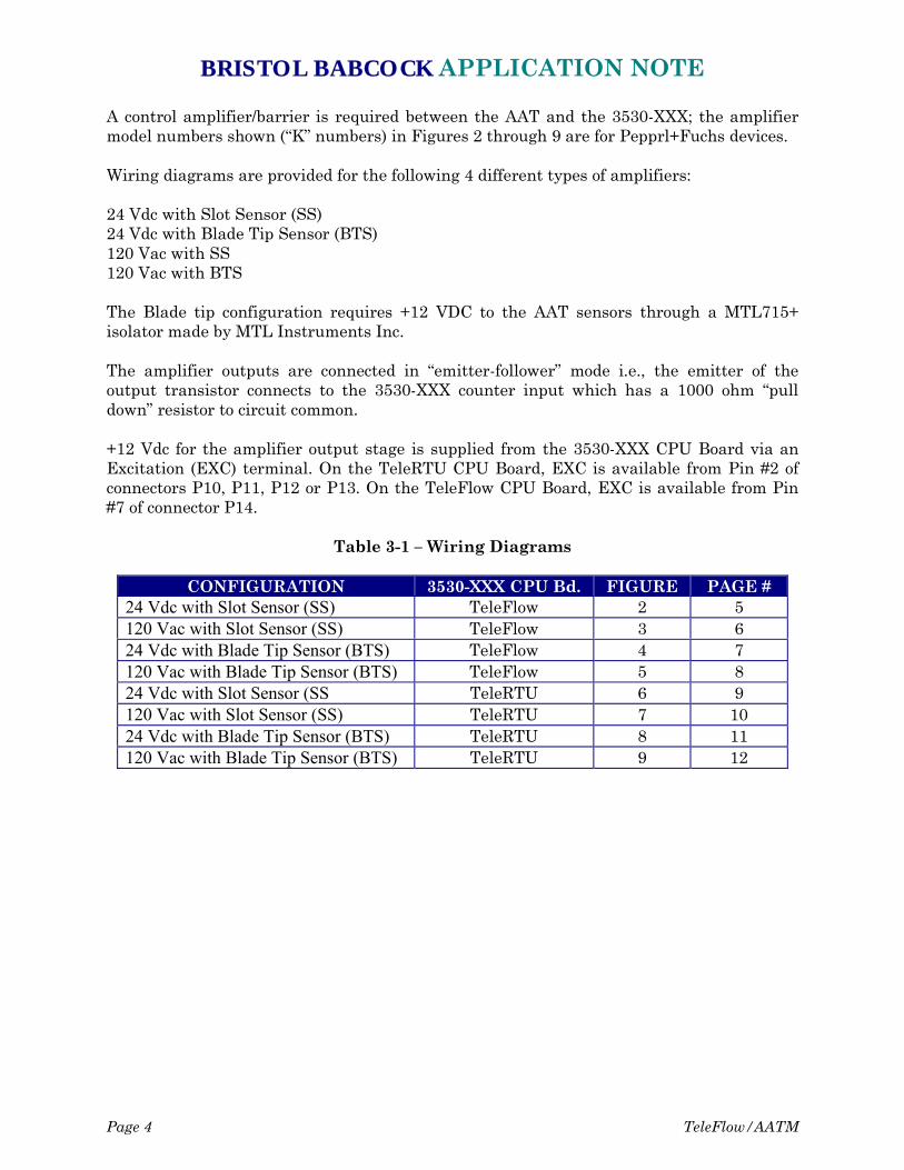
Table 3-1 – Wiring Diagrams
CONFIGURATION 3530-XXX CPU Bd. FIGURE PAGE #24 Vdc with Slot Sensor (SS) TeleFlow 2 5120 Vac with Slot Sensor (SS) TeleFlow 3 624 Vdc with Blade Tip Sensor (BTS) TeleFlow 4 7120 Vac with Blade Tip Sensor (BTS) TeleFlow 5 824 Vdc with Slot Sensor (SS TeleRTU 6 9120 Vac with Slot Sensor (SS) TeleRTU 7 1024 Vdc with Blade Tip Sensor (BTS) TeleRTU 8 11120 Vac with Blade Tip Sensor (BTS) TeleRTU 9 12
BRISTOL BABCOCK APPLICATION NOTE
TeleFlow/AATM Page 5
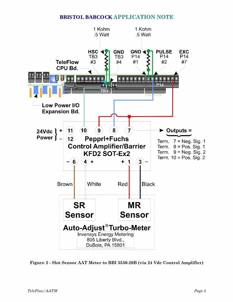
Figure 2 - Slot Sensor AAT Meter to BBI 3530-20B (via 24 Vdc Control Amplifier)
BRISTOL BABCOCK APPLICATION NOTE
Page 6 TeleFlow/AATM
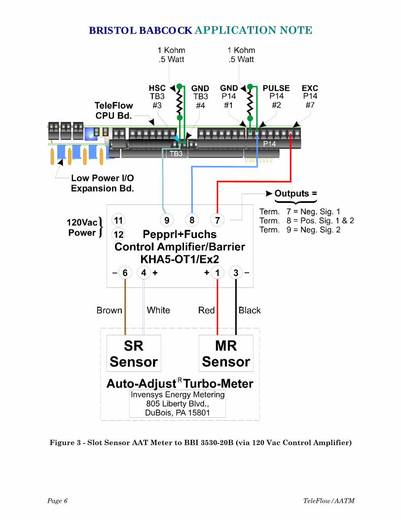
Figure 3 - Slot Sensor AAT Meter to BBI 3530-20B (via 120 Vac Control Amplifier)
BRISTOL BABCOCK APPLICATION NOTE
TeleFlow/AATM Page 7
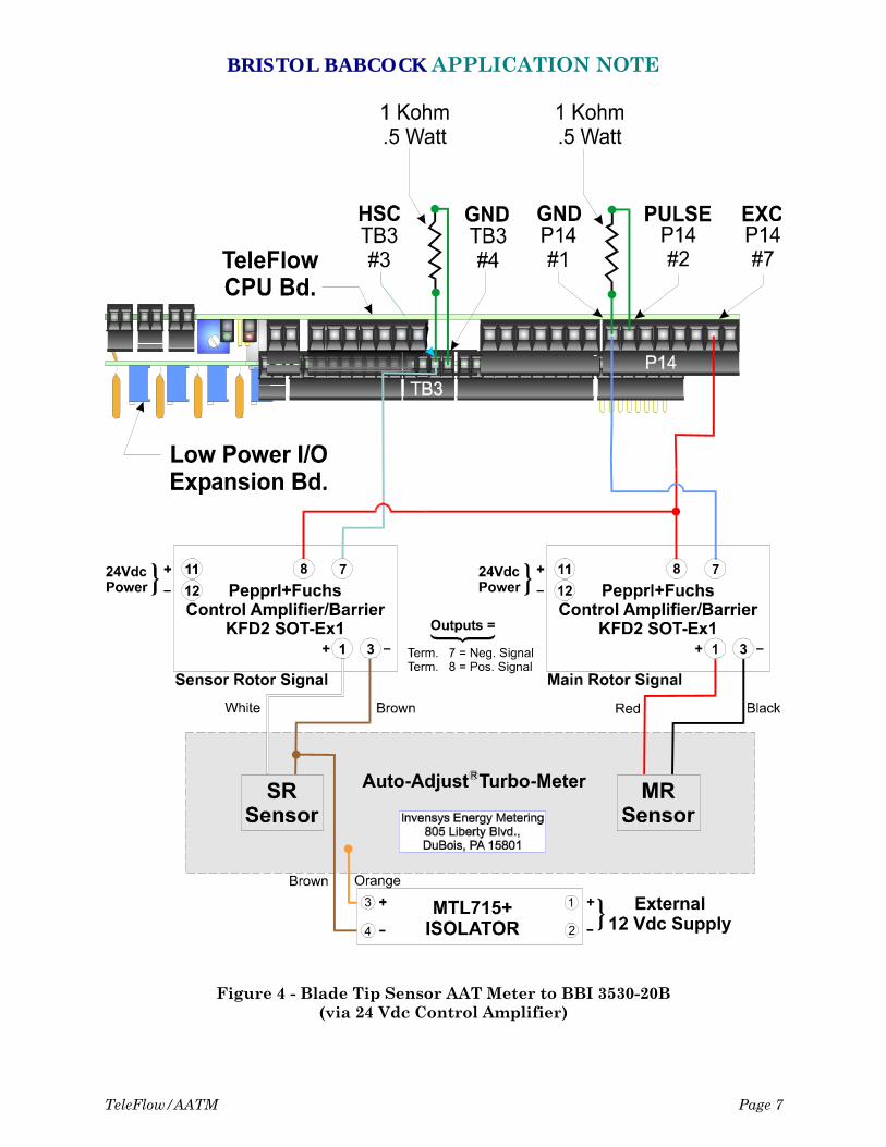
Figure 4 - Blade Tip Sensor AAT Meter to BBI 3530-20B(via 24 Vdc Control Amplifier)
BRISTOL BABCOCK APPLICATION NOTE
Page 8 TeleFlow/AATM
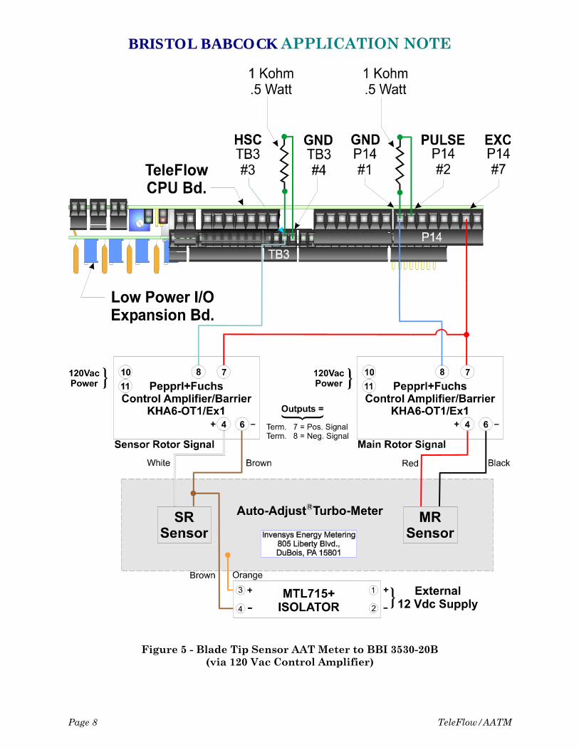
Figure 5 - Blade Tip Sensor AAT Meter to BBI 3530-20B(via 120 Vac Control Amplifier)
BRISTOL BABCOCK APPLICATION NOTE
TeleFlow/AATM Page 9
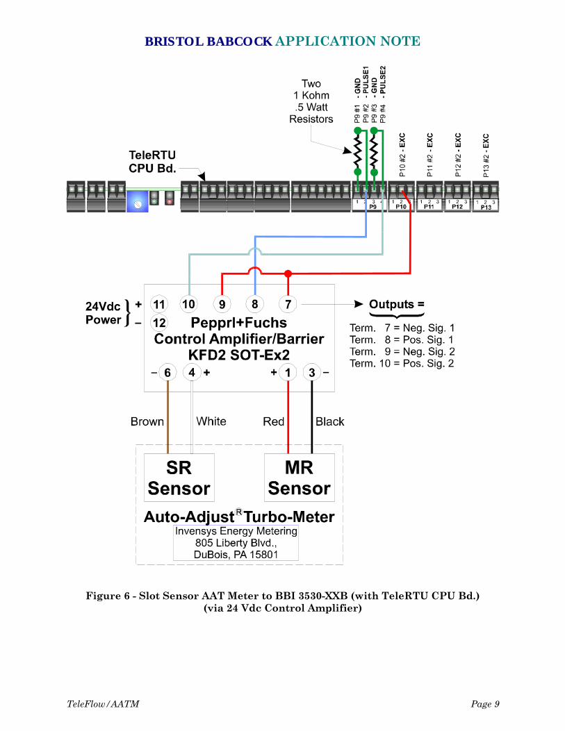
Figure 6 - Slot Sensor AAT Meter to BBI 3530-XXB (with TeleRTU CPU Bd.)(via 24 Vdc Control Amplifier)
BRISTOL BABCOCK APPLICATION NOTE
Page 10 TeleFlow/AATM
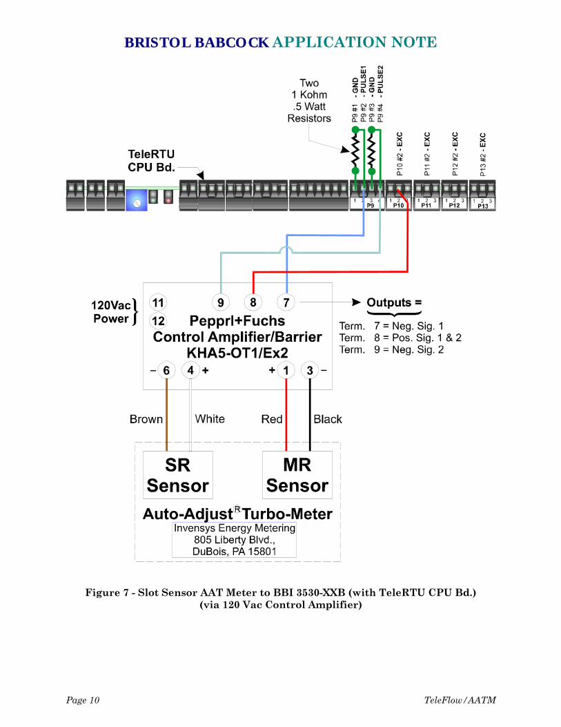
Figure 7 - Slot Sensor AAT Meter to BBI 3530-XXB (with TeleRTU CPU Bd.)(via 120 Vac Control Amplifier)
BRISTOL BABCOCK APPLICATION NOTE
TeleFlow/AATM Page 11
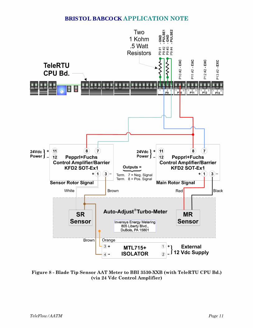
Figure 8 - Blade Tip Sensor AAT Meter to BBI 3530-XXB (with TeleRTU CPU Bd.)(via 24 Vdc Control Amplifier)
BRISTOL BABCOCK APPLICATION NOTE
Page 12 TeleFlow/AATM
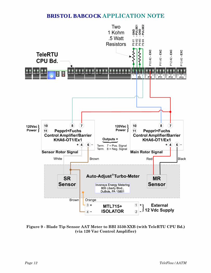
Figure 9 - Blade Tip Sensor AAT Meter to BBI 3530-XXB (with TeleRTU CPU Bd.)(via 120 Vac Control Amplifier)
BRISTOL BABCOCK APPLICATION NOTE
TeleFlow/AATM Page 13
Section 4 - Software Configuration
In order to access data from the Invensys Auto-Adjust Turbo-Meter, you will need toconfigure the AAT Module in your ACCOL Load. Full details on configuring the AATModule are included in the ‘AAT’ section of the ACCOL II Reference Manual (documentD4044).