Embed Size (px)
Citation preview

TeleFlow™Standard ACCOL
Load
(NOTE: This manual was formerly entitled ’TeleFlow™Standard ACCOL Load and Menus', TMS menus are nowdocumented in appendices of the TeleFlow hardware manual.)
&VMWXSP�&EFGSGO
D4087 Issue: December, 2000

The information in this document is subject to change without notice.Every effort has been made to supply complete and accurate information.However, Bristol Babcock assumes no responsibility for any errors thatmay appear in this document.
Bristol Babcock does not guarantee the accuracy, sufficiency or suitabilityof the software delivered herewith. The Customer shall inspect and testsuch software and other materials to his/her satisfaction before usingthem with important data.
There are no warranties, expressed or implied, including those ofmerchantability and fitness for a particular purpose, concerning thesoftware and other materials delivered herewith.
Request for Additional Instructions
Additional copies of instruction manuals may be ordered from the addressbelow per attention of the Sales Order Processing Department. List theinstruction book numbers or give the complete model, serial or softwareversion number. Furnish a return address that includes the name of theperson who will receive the material. Billing for extra copies will beaccording to current pricing schedules.
ACCOL is a trademark and Bristol is a registered trademark of BristolBabcock. Other trademarks or copyrighted products mentioned in thisdocument are for information only, and belong to their respectivecompanies, or trademark holders.
Copyright (c) 2000, Bristol Babcock, 1100 Buckingham St., Watertown,CT 06795. No part of this manual may be reproduced in any form withoutthe express written permission of Bristol Babcock.

i
A Few Words About Bristol Babcock
For over 100 years, Bristol has been providing innovative solutions for the measurement and control industry.Our product lines range from simple analog chart recorders, to sophisticated digital remote processcontrollers and flow computers, all the way to turnkey SCADA systems. Over the years, we have become aleading supplier to the electronic gas measurement, water purification, and wastewater treatment industries.
On off-shore oil platforms, on natural gas pipelines, and maybe even at your local water company, there areBristol Babcock instruments, controllers, and systems running year-in and year-out to provide accurate andtimely data to our customers.
Getting Additional Information
In addition to the information contained in this manual, you may receive additional assistance in using thisproduct from the following sources:
Contacting Bristol Babcock Directly
Bristol Babcock’s world headquarters are located at 1100 Buckingham Street, Watertown, Connecticut 06795 USA. Our main phone numbers are:
(860) 945-2200(860) 945-2213 (FAX)
Regular office hours are Monday through Friday, 8:00AM to 4:30PM Eastern Time, excluding holidays, andscheduled factory shutdowns. During other hours, callers may leave messages using Bristol’s voice mailsystem.
Telephone Support - Technical Questions
During regular business hours, Bristol Babcock’s Application Support Group can provide telephone supportfor your technical questions.
For technical questions regarding the TeleFlow Standard ACCOL load, other ACCOL products, Open BSIUtilities, as well as Bristol’s Enterprise Server®/ Enterprise Workstation® products, call (860) 945-2286.
For technical questions about the TeleFlow unit, and other Network 3000 hardware call (860) 945-2502.
For technical questions about ControlWave call (860) 945-2244 or (860) 945-2286.
For technical questions regarding Bristol’s OpenEnterprise product, call (860) 945-2501 or [email protected]
You can e-mail the Application Support Group at: [email protected]

ii
The Application Support Group also maintains a bulletin board for downloading software updates tocustomers. To access the bulletin board, dial (860) 945-2251 (Modem settings: 14.4K baud maximum, Noparity, 8 data bits, 1 Stop bit.)
For assistance in interfacing Bristol Babcock hardware to radios, contact Communication Technologies inOrlando, FL at (407) 629-9463 or (407) 629-9464.
Telephone Support - Non-Technical Questions, Product Orders, etc.
Questions of a non-technical nature (product orders, literature requests, price and delivery information, etc.)should be directed to the nearest regional sales office (listed below) or to your local Bristol sales office orBristol-authorized sales representative.
U.S. Regional Sales Offices Principal International Sales Offices:Northeast (Watertown) (860) 945-2262 Bristol Babcock Ltd (UK): (441) 562-820-001Southeast (Birmingham) (205) 980-2010 Bristol Babcock, Canada: (416) 675-3820Midwest (Chicago) (630) 571-6052 Bristol Meci SA (France): (33) 2-5421-4074Western (Los Angeles) (909) 923-8488 Bristol Digital Sys. Australasia Pty. Ltd. 61 8-9455-9955Southwest (Houston) (713) 685-6200 BBI, S.A. de C.V. (Mexico) (525) 254-2131
Please call the main Bristol Babcock number (860-945-2200) if you are unsure which office covers yourparticular area.
Visit our Site on the World Wide Web
For general information about Bristol Babcock and its products, please visit our site on the World Wide Webat: www.bristolbabcock.com
Training Courses
Bristol Babcock’s Training Department offers a wide variety of courses in Bristol hardware and software atour Watertown, Connecticut headquarters, and at selected Bristol regional offices, throughout the year.Contact our Training Department at (860) 945-2343 for course information, enrollment, pricing, andschedules.

iii
Who Should Read This Document?
This document is intended to be read by EGM 3530-xx TeleFlow users who areusing the standard software accompanying the TeleFlow™.
It assumes that the TeleFlow™ has been installed, and that all network cabling hasbeen connected and tested.
This document assumes familiarity with the following subjects:
" The requirements of their particular process or application.
" ACCOL programming. Anyone modifying the TeleFlow™ standard ACCOLload should be an experienced ACCOL programmer. For more information,consider attending an ACCOL training class. Also see An Introduction toACCOL (document# D4056), the ACCOL Workbench User Manual(document# D4051), and the ACCOL II Reference Manual (document#D4044).
" Universal Operator Interface (UOI) software. Anyone attempting to use thestandard TMS menus must be familiar with the UOI software tools. See theUOI Configuration Manual (document# D5074) and the UOI OperatorManual (document# D5075) for details.
EQUIPMENT APPLICATION WARNING
The user should note that a failure of this instrument or system, for whateverreason, may leave an operating process without protection. Depending upon theapplication, this could result in possible damage to property or injury to persons.It is suggested that the purchaser review the need for additional backupequipment or provide alternate means of protection such as alarm devices, outputlimiting, fail-safe valves, relief valves, emergency shutoffs, emergency switches,etc. If additional information is required, the purchaser is advised to contactBristol Babcock.

iv

v
Table of Contents
Chapter 1 - Introduction 1-1
Chapter 2 - TeleFlow™ Standard ACCOL Load 2-1
Appendix A - Modifying the TeleFlow™ Standard ACCOL Load A-1

BLANK PAGE

Chapter 1 - Introduction
TeleFlow™ 1-1 Standard ACCOL Load
What is the TeleFlow™ Standard ACCOL Load?
The TeleFlow™ Standard ACCOL Load is included on the TeleFlow™ diskette.This ACCOL load contains ACCOL modules specifically configured to performvarious natural gas calculations using a standard I/O setup. It is discussed in detailin Chapter 2 of this manual.
The TeleFlow™ Standard ACCOL Load is used in conjunction with the TeleFlowMenu System (TMS) menus (discussed below), and the TeleFlow™ EGM 3530Electronic Gas Measurement Computer.
For information on the TeleFlow™ Electronic Gas Measurement Computer, see theCI-3530-xx hardware manual for your particular TeleFlow™ model.
What Are the TMS Menus?
The TeleFlow Menu System (TMS) menus, which may be run on the PC, arespecifically configured to collect and display data from the TeleFlow StandardACCOL Load. These menus are discussed in detail in Appendix F of the appropriateTeleFlow™ hardware manual.
Modifying or Replacing the TeleFlow Standard ACCOL Load
The TeleFlow is a download-able ACCOL device, therefore, the TeleFlow StandardACCOL Load can be modified or replaced with another compatible ACCOL load.(See Appendix A for some notes about modifying the TeleFlow Standard ACCOLLoad.) For example, if the TeleFlow Standard ACCOL Load does not fit yourparticular application, you may modify the .ACC file in ACCOL Workbenchsoftware (available separately from Bristol Babcock,) re-build the ACL file, anddownload it into the TeleFlow . For more information on ACCOL Workbench, seethe ACCOL Workbench User Manual (document# D4051).
Be aware, also, that the TeleFlow Menu System (TMS) is closely tied to theTeleFlow Standard ACCOL Load. If you modify the standard load, or create adifferent load, you will need to modify the menus which make up TMS, using theUOI program (available separately from Bristol Babcock). For more information onUOI, see the UOI Configuration Manual (document# D5074).

BLANK PAGE

Chapter 2 - TeleFlow Standard ACCOL Load
TeleFlow™ 2-1 Standard ACCOL Load
Overview
The TeleFlow Standard load is a an ACCOL load (ACL file) that is intended for usein the EGM 3530 TeleFlow. This ACCOL load will compute gas flow rate, energyrate and volume and energy totals for a single Orifice meter run. Flow calculationsand data storage will be done according to the requirements of Chapter 21 of theAmerican Petroleum Institute Manual of Petroleum Measurement Standards(MPMS).
The TeleFlow Standard load supports the following functions:
" Gas flow calculations per AGA3 (1985) or AGA3 (1992) for an Orifice meter.
" Compressibility (Zf and Zb) per AGA8Detail or AGA8Gross when AGA3 (1992) isused.
" Supercompressibility (Fpv) per NX-19 when AGA3 (1985) is used.
" Energy (Btu/ft3) per AGA5 or from a fixed value.
" Raise/Lower flow rate control using a PID3TERM module and two Discreteoutputs.
" Pulse output on DO#1 with rate proportional to volume for odorant injection.
" An Audit Trail holding 200 events and 200 alarms for a total of 400 entries.
" A Daily Archive file containing 35 days of Daily historical information.
" A Periodic Archive file containing 35 days of Hourly historical information.
" A Trend Archive file containing 8 days of 15 minute trend information (can bedisabled).
" Support of a local 2 line display (LCD) and single push-button.
" Local and Network communications.
" Backflow detection and alarming.
" Nomination alarm settings.
" Input sampling, averaging and Extension calculation every second.

Chapter 2 - TeleFlow Standard ACCOL Load
TeleFlow™ Standard ACCOL Load2-2
" Configurable 1, 2, 5, 15, and 60 second calculation interval.
" Pulse counting and scaling.
" Configurable automatic dial-out on alarm occurrence. (NOT YET SUPPORTED)
" Control of an external radio.
" Battery charge regulator.
The main task of the TeleFlow Standard Load executes every second and 'wakes up'the hardware (out of low-power mode) and collects 'live' Differential Pressure (DP),Static Pressure (P) and Temperature (T) input data and status data from theinternal sensor conditioning circuitry. In accordance with the API MPMS, Chapter21 requirements, these are averaged over the configured Calculation interval foruse in the flow calculations; averaging is 'flow-dependent' in that it only occurswhen the DP value is above a configured 'cutoff' level.
The live DP and P values are used to compute an Extension value (the square rootof the product of the live DP and P) every second; Extension values are added overthe Calculation interval, which can be configured at 1, 2, 5, 15 or 60 seconds. Theinterval is configured by the user to obtain the best balance of power consumptionand calculation rate. If a calculation is not scheduled the task completes and thehardware re-enters sleep mode.
At the end of a Calculation interval a full flow calculation is performed. Averagedinput values for the interval are used in the FPV, AGA8Detail, or AGA8Grossmodules to obtain gas compressibility factors. These are then used in an AGA3(1985 or 1992) equation to compute the flow rate in MSCF per hour. The Extensionused in the AGA3 calculation is an average Extension for the Calculation interval
NOTE:
The EGM 3530 only supports a subset of the ACCOL module library thus someACCOL modules will not operate. See the ’Hardware and Software Requirements’section of the ACCOL II Reference Manual (document# D4044) to find out whichmodules are supported.
In addition, the EGM-3530 will not provide some functions that are common inBristol products; among these are Communication Statistics, Crash Blocks, On-lineDiagnostics, Task slip information, and Task rate information.

Chapter 2 - TeleFlow Standard ACCOL Load
TeleFlow™ 2-3 Standard ACCOL Load
obtained by summing the Extensions computed every second during the intervaland dividing by the number of Extension values summed. The Extension sum isthen cleared and averages are reset for another Calculation interval.
There are several conditions, which force the Calculation interval to be 1 second asfollows.
1. When the Local communications port is in use.
2. When the LCD Display is active (i.e scrolling data for the operator).
3. When PID flow control is active and the flow rate is not within 2% of thesetpoint.
4. When the Network Port is active (Carrier Detect is high)
In addition to the input signal averages for the Calculation interval, another set ofinput averages is maintained for each full log period (hour or 15 min) and day;these averages are stored in the Archive for that log.
Process Inputs: Differential Pressure (DP), Static Pressure (P),Temperature (T)
The process inputs used for the Gas Flow computations are Differential Pressure(DP), Static Pressure (P), and Temperature (T). The DP and P come from theinternal, multivariable sensor; the Temperature is measured by an RTD probe.Each second, these values are acquired from the internal sensor and placed in the'live data' signals.
Input Averaging
The process inputs DP, P and T 'live data' values are averaged over the configuredCalculation interval; the average is a 'flow-dependent time-weighted' value inaccordance with MPMS requirements. The averages are calculated for the periodsof time when the DP is above the user configured Cutoff level. When there is noflow for the entire Calculation interval, straight arithmetic averages are calculatedfor the Static Pressure and Temperature. At the end of each Calculation intervalthe calculated averages are stored in the 'in-use' signals and used to calculate flowrate and volume.
Separate averages of DP, P, and T are maintained for each log period (hour or 15min) and the day.

Chapter 2 - TeleFlow Standard ACCOL Load
TeleFlow™ Standard ACCOL Load2-4
Input Override and Calibration Mode
The 'in use' signals can be 'frozen' at their current value by setting their standardACCOL Control Inhibit (CI) on. When an 'in-use' signal (DP, P, or T) is in 'CI' mode,the 'live data' signal continues to reflect the current value from the internal sensor,however, the 'in-use' signal is no longer updated and remains 'frozen' at its currentvalue. Input averaging continues to be performed using the 'in-use' value ratherthan the 'live data' value.
While the 'in-use' signals are in CI mode the Operator can enter an 'Override' valueinto the signal for use in the input averaging and Gas Flow calculation.
When the CALIB (Calibration mode) signal is set ON all the DP, P, and T 'in-use'signals are simultaneously placed in CI mode.
Input Alarms
The process inputs DP, P, and T are alarm signals with the following default alarmlimits:
Low High LowLow HighHigh LDb HDb
DP 10 250 0 300 3 10P 100 1500 0 2000 10 50T 50 150 32 250 3 10
Digital Inputs
Inputs 1 and 2 are free for general use and can be used as alarm inputs ormonitoring inputs. The default alarm condition is the ON state, i.e. the alarmoccurs when the input enters its ON state. These inputs are updated once a second.
Digital Outputs
The discrete outputs are shared by the Flow control and Sampler function.
When Flow control is enabled:DO 1 - Raise pulse output.DO 2 - Lower pulse output.

Chapter 2 - TeleFlow Standard ACCOL Load
TeleFlow™ 2-5 Standard ACCOL Load
When Sampler output is enabled:DO 1 - Pulse output based on volume (to drive an external totalizer or sampler).DO 2 - general-purpose output.
Sampler logic has a default volume of 100 mscf and a default pulse width of 1second.
Flow control has priority for the discrete outputs so that if both Sampler output andFlow control are enabled, Sampler will be shut off and Flow control will use theoutputs.
Auxiliary Analog Input
This input is scaled for 1 to 5 volts, but up to 16 volts can be applied; it can be usedas an alarm or monitoring input. Signals are provided that allow this input to bescaled into other units. Voltages higher than 5 volts are scaled accordingly, i.e. 10volts=200%, 15 volts=300%, etc.
The default scaling is:
Zero = 0.0 % (1 volt input)Full scale = 100.0 % (5 volts input)
Default alarm limits are: Low 10%High 100%Lo-lo 0%Hi-hi 150%LDb 3%HDb 10%
This input is updated once each calculation interval.
Pulse Input
This input accepts pulses at rates up to 5,000 Hz and keeps a running pulse totaland frequency value. A scaling factor can be configured to convert pulses into otherunits i.e., if each pulse is the equivalent of 5 gallons a scaling factor of 5 makes thetotal be in gallon units. The frequency and total can be read in 'raw' units (countsand Hertz) and also in scaled units. Default pulse scaling factor is 1.0.

Chapter 2 - TeleFlow Standard ACCOL Load
TeleFlow™ Standard ACCOL Load2-6
Communications Port Assignments
PORT #1 - Pseudo-slave local port, 19200 bps.PORT #2 - BSAP network port, 9600 bps.
The baud rate and the RTS/CTS delay may be changed on-line.
Communication Port Usage
The Local port is used for local configuration and data collection. It usually connectsto a PC or Laptop that is running a user-interface software package like TMS orUOI. The Local port will respond to any address; therefore it CANNOT be used in amulti-drop connection. Only the Network port can be multi-dropped (with thenecessary external RS-485 converters).
The Network port is used generally for data collection via Bristol Peer-to-peermessages coming from another Bristol device such as a Data Concentrator; for thiskind of data collection a number of defined lists are provided as well as Slavemodules for each list. This port can also be used for data collection or configurationby software such as Open BSI, UOI, TMS, or other third party BSAP protocol basedcommunication systems. The Network port will not respond to messages unless itsDCD input is high.
Gas Flow Calculations
Either the 1985 or 1992 AGA3 calculations can be selected; 1985 calculations aresuitable for both Flange and Pipe taps; 1992 calculations only use Flange taps.AGA3 calculations are performed at the end of the configured Calculation interval.(Note: Maximum power conservation is achieved by using the longest calculationcycle.)
The Calculation interval is user configurable at 1, 2, 5, 15, or 60 seconds. Undercertain conditions the Calculation interval is forced to 1 second. These conditionsare:
The Local Communications port is in use.
The LCD Display button has been pushed and the unit is scrolling the Display List.
The unit is in 'charge regulation' mode

Chapter 2 - TeleFlow Standard ACCOL Load
TeleFlow™ 2-7 Standard ACCOL Load
The flow control is active and not close to the setpoint.
Super-compressibility (Fpv) and Compressibility ( Zs, Zb, Zf)
When the 1985 AGA3 calculation is selected, the Super-compressibility (Fpv) valueis calculated using the NX-19 equations. When the 1992 AGA3 calculation is usedthe Flowing (Zf) and Base (Zb) compressibility factors are calculated using either theAGA8Detail or AGA8Gross module. The AGA8Gross module provides either theG,C,N or HV, G, C modes.
If the Base Pressure or Base Temperature differ from Standard conditions (14.73psia, 60 oF) and the 1992 AGA3 calculation is in use, an AGA8Detail or AGA8Grossmodule will be executed to calculate standard compressibility Zs for the defined gascomposition. The calculation of Zs will be done once per minute or whenever arelated gas constant changes.
Flow Rates
Gas Flow-rate is calculated in mscf/hr using an AGA3Term module if the 1985calculation is selected, otherwise the AGA3Iter module (1992 calculation) is used.Because of MPMS requirements the Extension value is supplied to these modulesexternally.
Flow rate in mscf/hr is converted to mscf/day and is available for reading.
Flow Rate Alarm
The flow rate signal is an alarm signal with default alarm limits (in mscf/hr):
Low 0High 3000Lo-lo 0Hi-hi 5000LDb 50HDb 50
Flow Volume Totals
At the end of each Calculation interval the volume for that interval is added tototals for the hour, day, current month and 'running' totalized volume. At the end ofeach hour, day, and month the accumulated volume for that period is stored and

Chapter 2 - TeleFlow Standard ACCOL Load
TeleFlow™ Standard ACCOL Load2-8
the total cleared for the next period. The running total is not cleared; it accumulatesto 10 million at which point it rolls over to zero and continues accumulating.
Averaged Extension
The average value of the Extension ( square root of the product of process DP andabsolute Static Pressure) is computed for each log period (hour or 15 min) and forthe day and saved in an archive. This average is maintained separately from thevalue used in calculating the flow volume for a Calculation interval.
Back Flow
The time spent in a Back Flow condition is totaled for the current and previous dayand an alarm is generated if the condition exceeds a user-specified limit. As eachinput sample is processed, the DP reading is examined to see if a Back Flowcondition is present.; (i.e. DP is less than 0.0 and the absolute value of DP is greaterthan the DP Cutoff). If a Back Flow condition is detected, a Back Flow timer isstarted. If the Back Flow condition remains in effect for a user configured numberof seconds, a Logical Alarm signal is turned 'ON'.
The amount of time during which a Back Flow condition has been detected for thecurrent day is accumulated in an Analog signal. At the end of the contract day, thevalue in this signal is transferred into the previous day's Back Flow Time signaland the signal is set to 0.0. All intervals of Back Flow are accumulated,independent of the alarm state. (i.e. Short durations of Back Flow, less than theBack Flow timer, are accumulated even though the Back Flow Alarm is not turned'ON'.)
Gas Energy Calculations
Gas flow volume for a Calculation interval is converted to energy in MMBTU (i.e. DekaTherms; a DekaTherm is 10 million Btu) by multiplying by a Heating value inBTU/cu.ft. and dividing by 10 million; the Heating value can come from a fixedvalue or from an AGA5 calculation.The energy for the interval is summed to produce an energy total in MMBTU forthe each hour and day, and for the current month.
Flow rate is converted to energy rate in MMBTU/hr.

Chapter 2 - TeleFlow Standard ACCOL Load
TeleFlow™ 2-9 Standard ACCOL Load
Low-Flow Cut-OFF
The 'live' Differential pressure is always compared to a CUTOFF signal set ininches of water. When the DP value drops below the value of the CUTOFF signal,flow calculation will cease and the calculated flow-rate will be zero. Default cutoff is0.25 inches of H2O.
Flow Time
While the DP is above the Cutoff limit the unit will accumulate a flow-time countin minutes for the hour and day. In a backflow condition a separate backflow timeis accumulated.
Archive Files
Periodic Archive
The interval is 1 hour. At the end of the interval, the information shown below iswritten into a periodic archive file. If log break is enabled, these values are writtenwhen a configuration value changes.
DATE/TIMELOCAL SEQUENCE NUMBERGLOBAL SEQUENCE NUMBERAVERAGE DP INH2OAVERAGE STATIC PRESSURE PSIGAVERAGE FLOWING TEMP. DEGFFLOW TIME MINSAVERAGE EXTENSIONACCUMULATED VOLUME MSCFACCUMULATED ENERGY MMBTUAVERAGE AUXILIARY INPUT %
Daily Archive
At the end of every day the information shown below is written into a daily archive

Chapter 2 - TeleFlow Standard ACCOL Load
TeleFlow™ Standard ACCOL Load2-10
file.
DATE/TIMELOCAL SEQUENCE NUMBERGLOBAL SEQUENCE NUMBERAVERAGE DP INH2OAVERAGE STATIC PRESSURE PSIGAVERAGE FLOWING TEMP. DEGFFLOW TIME MINSAVERAGE EXTENSIONACCUMULATED VOLUME MSCFACCUMULATED ENERGY MMBTUAVERAGE AUXILIARY INPUT %
Trend Archive
If the Trend log is enabled then every 15 minutes the live (not averaged) inputvalues are written to a trend archive as shown below.
DATE/TIMELOCAL SEQUENCE NUMBERGLOBAL SEQUENCE NUMBERDIFF. PRESSURE INH2OSTATIC PRESSURE PSIGFLOWING TEMP. DEGF
Log Break
When the Log Break option is enabled archive log-break will occur when the Orificeplate size or other flow-related constant is changed.
Flow Control
Raise/lower Flow-rate control is achieved using a PID3TERM Module. The FlowController uses a FLOW SETPOINT signal and the calculated flow rate signal asinputs to the PID3TERM module, the output of which generates raise/lower pulseson the discrete outputs (Raise on DO#1, Lower on DO#2).
Default settings are:

Chapter 2 - TeleFlow Standard ACCOL Load
TeleFlow™ 2-11 Standard ACCOL Load
Gain 1Integral 1 repeat/minDerivative 0 minsDeadband 0Valve travel 30 secsPulse width 1 secMax rate 5000 mscf/hr
Radio Control
Two radio control functions are available; Scheduling and Sensing (also called 'Fastradio'). Radio Scheduling is used to conserve battery power by allowing the radio tobe powered up for a short time every day in expectation of receiving a message froma remote 'host' during that time. If Radio Scheduling is enabled, the system will turn ON the radio at a defined time(an hour of the day) and keep it on for a defined length of time, usually in a periodof minutes. A user-configured 'listen' timer is also started so that if no messages arereceived while the timer is running the radio will turn OFF to save power. Theradio can also be activated manually for testing via the local port. Radio power iscontrolled using a system signal that turns an auxiliary power output ON or OFF.
If Radio Sensing is enabled the system will turn the radio on at a defined time (anhour of the day) and begin a sequence in which the radio is turned ON every somany seconds but for 'listen' time intervals less than 1 second. It continues thissequence until the defined 'stop' hour is reached. If a message is received while theradio is ON the system will keep the radio ON, process the message and respond.After every response the radio remains ON for one more 'listen' time, after which itis shut OFF.
Both radio control functions can be active simultaneously.
Modem Dial-Out (THIS FUNCTION IS NOT YET SUPPORTED)
This feature makes use of the ACCOL Slave Auto-dial function. When DIALOUT isenabled and a trigger condition is satisfied the load will automatically dial a phonenumber (the modem option must be installed) held in the Dial List. The number ofthe Dial list is held in system signal #DIAL.001. Up to 13 different triggerconditions can be armed to initiate the call. Program logic examines the state of thesignal associated with an 'arm' signal and, should it be in an Alarm state, sets anon-zero value into the Dial Enable signal in the Dial List to start the call. The dial
Chapter 2 - TeleFlow Standard ACCOL Load
TeleFlow™ Standard ACCOL Load2-12
commands sent to the modem (i.e. initialization, phone number) are defined bysignals in the Dial list.
The use of the modem dial out function implies that the called device has been setup to 'know' that it should poll for alarms after it answers the call and then hang-up.
Dialing logic will dial the first phone number three times and then dial a secondnumber three times, the combination constituting one 'dial-attempt'. To conservepower the maximum number of attempts per hour is two; this value can beconfigured up to 9 by the user.
Battery Charge Control
Signals are provided to allow charge regulator setup and control for either a 6 or 12volt battery. Should the charge regulator detect battery overcharge, an alarmoccurs, and a shunt regulator is activated which deactivates the solar panel,thereby preventing an overcharge condition.
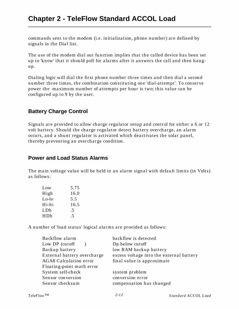
Power and Load Status Alarms
The main voltage value will be held in an alarm signal with default limits (in Volts)as follows:
Low 5.75High 16.0Lo-lo 5.5Hi-hi 16.5LDb .5HDb .5
A number of 'load status' logical alarms are provided as follows:
Backflow alarm backflow is detectedLow DP (cutoff ) Dp below cutoffBackup battery low RAM backup batteryExternal battery overcharge excess voltage into the external batteryAGA8 Calculation error final value is approximateFloating-point math errorSystem self-check system problemSensor conversion conversion errorSensor checksum compensation has changed

Chapter 2 - TeleFlow Standard ACCOL Load
TeleFlow™ 2-13 Standard ACCOL Load
Audit/Event Log
The EAUDIT module (in Task 0) is set up to collect both alarms and events, withevent signals defined by the signals in list 23. The module is defined with enoughspace for 400 alarms and events, and the module operates such that 200 alarms and200 events are kept separate until the Audit log is collected. This design prevents atoggling alarm or event from filling the entire alarm/event log buffer to theexclusion of all other entries.
Gas Data Lists For Master Node Access
Data lists are provided to support the gathering of gas data from a master node viathe Network port using Bristol peer-to-peer messages. The associated slave pointnumber is shown. Lists without slave points can only be read using Open BSIDataView.
LIST 10 Full Configuration
Firmware revision (progrev)Unit IDMeter IDMeter numberAlarm report formatAlarm report format 1Display alarmsFlow equationBase pressureBase temperaturePipe materialOrifice materialAGA8 MethodAGA8 Gross modeContract hourPipe diameterPipe ref temperatureTap locationTap typeOrifice diameterOrifice ref temperatureLow DP cutoff

Chapter 2 - TeleFlow Standard ACCOL Load
TeleFlow™ Standard ACCOL Load2-14
DP Full scale pressureDP Pressure zeroSP Full scale pressureSP Pressure zeroTemperature full scaleTemperature zeroRate lo-loRate loRate hiRate hi-hiRate hi deadbandRate lo deadbandDP lo-loDP loDP hiDP hi-hiDP hi deadbandDP lo deadbandSP lo-loSP loSP hiSP hi-hiSP hi deadbandSP lo deadbandTemp lo-loTemp loTemp hiTemp hi-hiTemp hi deadbandTemp lo deadbandBatt lo-loBatt loBatt hiBatt hi-hiBatt hi deadbandBatt lo deadbandBarometric pressureSpecific heat ratioHeating value fixedHeating value sourceSpecific gravityGravity typeViscosityCH4
Chapter 2 - TeleFlow Standard ACCOL Load
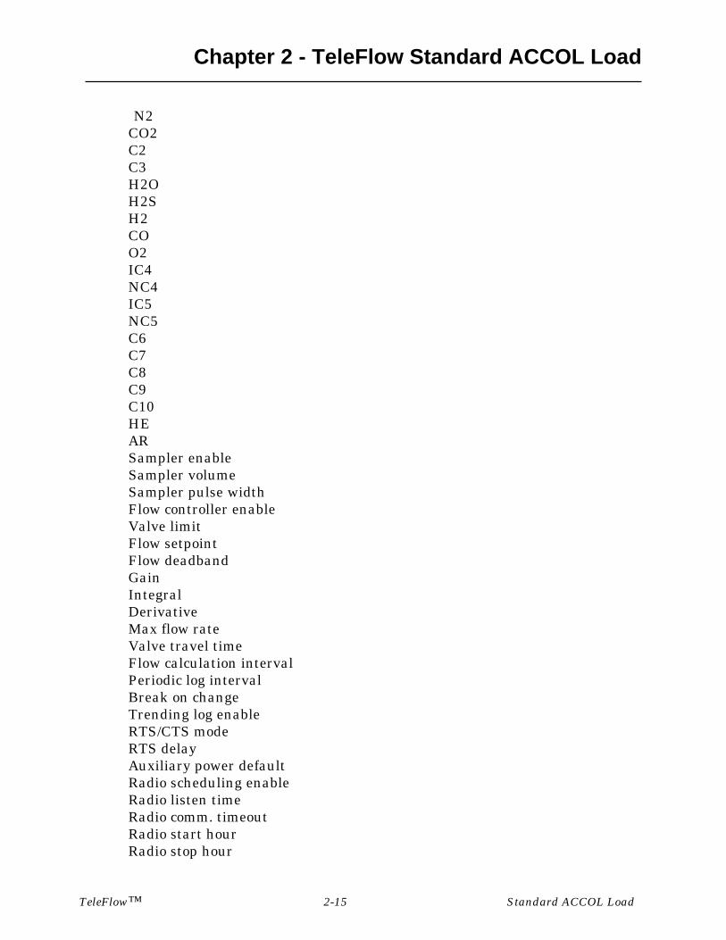
TeleFlow™ 2-15 Standard ACCOL Load
N2CO2C2C3H2OH2SH2COO2IC4NC4IC5NC5C6C7C8C9C10HEARSampler enableSampler volumeSampler pulse widthFlow controller enableValve limitFlow setpointFlow deadbandGainIntegralDerivativeMax flow rateValve travel timeFlow calculation intervalPeriodic log intervalBreak on changeTrending log enableRTS/CTS modeRTS delayAuxiliary power defaultRadio scheduling enableRadio listen timeRadio comm. timeoutRadio start hourRadio stop hour
Chapter 2 - TeleFlow Standard ACCOL Load
TeleFlow™ Standard ACCOL Load2-16
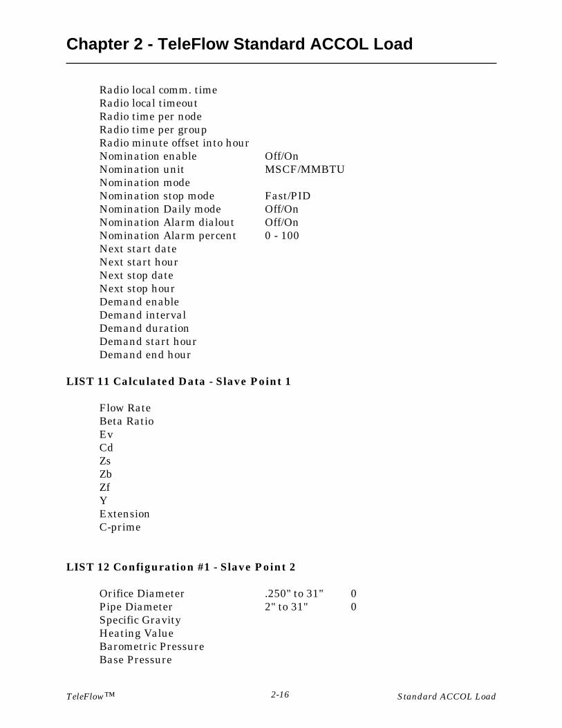
Radio local comm. timeRadio local timeoutRadio time per nodeRadio time per groupRadio minute offset into hourNomination enable Off/OnNomination unit MSCF/MMBTUNomination modeNomination stop mode Fast/PIDNomination Daily mode Off/OnNomination Alarm dialout Off/OnNomination Alarm percent 0 - 100Next start dateNext start hourNext stop dateNext stop hourDemand enableDemand intervalDemand durationDemand start hourDemand end hour
LIST 11 Calculated Data - Slave Point 1
Flow RateBeta RatioEvCdZsZbZfYExtensionC-prime
LIST 12 Configuration #1 - Slave Point 2
Orifice Diameter .250" to 31" 0Pipe Diameter 2" to 31" 0Specific GravityHeating ValueBarometric PressureBase Pressure

Chapter 2 - TeleFlow Standard ACCOL Load
TeleFlow™ 2-17 Standard ACCOL Load
Base TemperatureFlowing ViscosityRatio of Specific HeatTap LocationTap TypeDp Cutoff
LIST 13 Configuration #2 - Slave Point 3
Firmware version (progrev)Meter NumberFlow Equation 1985/1992Calculation IntervalContract HourLogging IntervalBreak Log optionHeat Value sourceGravity typeAGA8 MethodAGA8 Gross Mode
LIST 14 Controller - Slave Point 4
Sampler Enable On/OffSampler Volume 0 - 10000 MCFSampler Duration 1.0 SecsFlow Rate Control Off/OnValve Limiting Off/OnSetpoint 0 MSCFDeadband 0Gain 0-100Integral 0-60 RPTS/Min 1Derivative 0-60 Min 0Valve Travel Time 1-30 SEC 30Maximum Flow Rate 5000 MSCF 5000Nomination enable Off/OnNomination unit MSCF/MMBTUNomination modeNomination stop mode Fast/PIDNomination Daily mode Off/OnNomination Alarm dialout Off/OnNomination Alarm percent 0 - 100Next start date

Chapter 2 - TeleFlow Standard ACCOL Load
TeleFlow™ Standard ACCOL Load2-18
Next start hourNext stop dateNext stop hour
LIST 15 AGA8 Gross Config
Specific GravityHeating ValueCO2 contentNitrogen contentAGA8 Gross ModeGravity type
LIST 16 AGA8 Detail Gas composition
MethaneNitrogenCO2EthanePropaneH2OH2SH2COO2I-ButaneN-ButaneI-PentaneN-PentaneHexaneHeptaneOctaneNonaneDecaneHeliumArgon
LIST 17 AGA3 1985 Factors
Flow RateBeta RatioFpb
Chapter 2 - TeleFlow Standard ACCOL Load
TeleFlow™ 2-19 Standard ACCOL Load
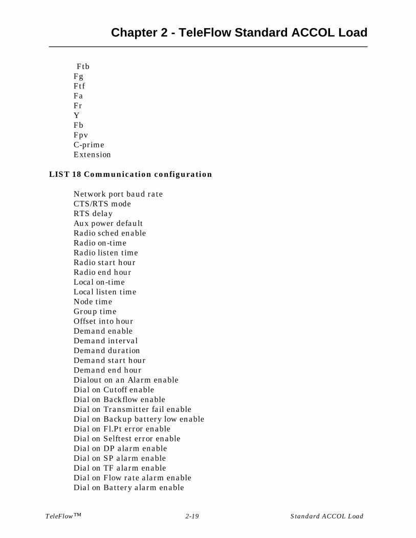
FtbFgFtfFaFrYFbFpvC-primeExtension
LIST 18 Communication configuration
Network port baud rateCTS/RTS modeRTS delayAux power defaultRadio sched enableRadio on-timeRadio listen timeRadio start hourRadio end hourLocal on-timeLocal listen timeNode timeGroup timeOffset into hourDemand enableDemand intervalDemand durationDemand start hourDemand end hourDialout on an Alarm enableDial on Cutoff enableDial on Backflow enableDial on Transmitter fail enableDial on Backup battery low enableDial on Fl.Pt error enableDial on Selftest error enableDial on DP alarm enableDial on SP alarm enableDial on TF alarm enableDial on Flow rate alarm enableDial on Battery alarm enable

Chapter 2 - TeleFlow Standard ACCOL Load
TeleFlow™ Standard ACCOL Load2-20
Dial on Auxiliary input alarm enableDial on Charger alarm enableDial on Nomination alarm enable
LIST 20 Live Data
Diff pressureStatic pressureTemperatureFlow rateOperator change
LIST 21 Rate and Volume - Slave Point 5
Flow rateFlow rate @ StdEnergy rateDaily flow rateFlow time todayVolume todayEnergy todayFlow time yesdayVolume yesdayEnergy yesdayVolume this monthEnergy this monthVolume totalizerEnergy totalizerVolume last monthEnergy last monthScaled frequencyScaled pulses todayScaled pulses yesterdayScaled pulses total
LIST 22 Inputs - Slave Point 6
Diff pressureStatic pressureTemperatureSystem power voltsPower input 1 voltsPower input 2 volts

Chapter 2 - TeleFlow Standard ACCOL Load
TeleFlow™ 2-21 Standard ACCOL Load
Backup battery voltsPC board temperatureAuxiliary inputTotal pulsesPulse FrequencyDO#1DO#2DI#1DI#2
LIST 50 LCD Display list
Meter IDSystem powerAux inputDiff pressureFlowing pressureTemperatureDaily flow rateFlow time todayVolume todayVolume yesdayVolume totalizer

BLANK PAGE

Appendix AModifying the TeleFlow Standard ACCOL (TSA) Load
TeleFlow™ A-1 Standard ACCOL Load and Menus
Modifying or Replacing the TeleFlow Standard ACCOL Load & Menus
The TeleFlow is a download-able ACCOL device, therefore, the TeleFlow StandardACCOL Load can be modified or replaced with another compatible ACCOL load.
For example, if the TeleFlow Standard ACCOL Load does not fit your particularapplication, you may modify the .ACC file in ACCOL Workbench software(available separately from Bristol Babcock,) re-build the ACL file, and download itinto the TeleFlow . For more information on ACCOL Workbench, see the ACCOLWorkbench User Manual (document# D4051).
Be aware, also, that the TeleFlow Menu System (TMS) is closely tied to theTeleFlow Standard ACCOL Load. If you modify the standard load, or create adifferent load, you will need to modify the menus which make up TMS, using theUOI program (available separately from Bristol Babcock). For more information onUOI, see the UOI Configuration Manual (document# D5074).
Another restriction on modifying the ACCOL load is that the communication portsand process I/O boards must be configured consistently with the design of theTeleFlow. Table 1-1, below, shows the required port configuration; Table 1-2, showsthe required process I/O configuration.
Table 1-1 Process I/O Board OptionsI/O Slot Number Process I/O Board Name Syntax in ACC File1 Digital Input Board with 2 or
10 points (or no boardinstalled)
DI2DI10
2 Digital Output Board with 2or 10 points (or no boardinstalled)
DO2DO10
NOTE:
The TeleFlow only supports a subset of the ACCOL module library thus someACCOL modules will not operate. See the 'Hardware and Software Requirements'section of the ACCOL II Reference Manual (document# D4044) to find out whichmodules are supported.
In addition, the EGM-3530 will not provide some functions that are common inBristol products; among these are Communication Statistics, Crash Blocks, On-lineDiagnostics, Task slip information, and Task rate information.

Appendix AModifying the TeleFlow Standard ACCOL (TSA) Load
TeleFlowTM Standard ACCOL Load and MenusA-2
3 Analog Input Board with 1, 4,5, or 8 points (or no boardinstalled)
AI1AI4AI5AI8
4 High Speed Counter Boardwith 1, 2, or 3 points (or noboard installed)
HSC1HSC2HSC3
5 Analog Output Board with 1point (or no board installed)
AO1
Table 1-2 Communication Port OptionsPORT Port Type Baud Rate NotesA Pseudo Slave 300 - 38,400 Asynchronous
Local PortB Slave 300 - 38,400 Asynchronous
Network PortC Master 300 - 38,400 Asynchronous
Expanded I/O Port
NOTES ON POWER CONSUMPTION:
Assuming the Local Port is unused, the Network port is inactive, and the LCDdisplay is inactive, the 3530 will enter 'sleep' mode if it is not currently executingan ACCOL task.
The larger the ACCOL load, the longer it takes to execute, and the longer the unit'stays awake'. Load functions should be scheduled to run only when needed. Thismeans using logical signals as flags to control execution. Load tasks should becarefully partitioned to execute only when necessary, so that maximum 'sleep' timeis obtained, thereby reducing power consumption.

READER RESPONSE FORM
Please help us make our documentation more useful to you! If you have acomplaint, a suggestion, or a correction regarding this manual, please tell us bymailing this page with your comments. It’s the only way we know we’re doing ourjob by giving you correct, complete, and useful documentation.
DOCUMENT NUMBER: D4087TITLE: TeleFlow Standard ACCOL LoadISSUE DATE: December, 2000
COMMENT/COMPLAINT:
______________________________________________________________________________
______________________________________________________________________________
______________________________________________________________________________
______________________________________________________________________________
______________________________________________________________________________
______________________________________________________________________________
______________________________________________________________________________
______________________________________________________________________________
______________________________________________________________________________
______________________________________________________________________________
______________________________________________________________________________
______________________________________________________________________________
______________________________________________________________________________
Mail or FAX this page to:Bristol Babcock Inc.1100 Buckingham StreetWatertown, CT 06795FAX#: (860) 945-2213Attn: Technical Publications Group, Dept. 610 RRF - 12/2000

&VMWXSP�&EFGSGO�-RG�an FKI company
1100 Buckingham StreetWatertown, CT 06795
Telephone: (860) 945-2200


![J Y I' A'I'I If - ILSLila.ilsl.br/pdfs/v32n1a07.pdf · I'f'ct. ] nability to do so was ]'l'col'ded as "blind," in accol'(lancc with critf'l'ia laid down hy the Intcrnational Asso(·iation](https://img.pdfslide.us/doc/110x75/5e6b1e80bc722220031fca69/j-y-i-aii-if-ifct-nability-to-do-so-was-lcolded-as-blind.jpg)