Embed Size (px)
Citation preview
ANSI/ISA-RP12.6-1995Approved August 24, 1995
Recommended Practice
Wiring Practices for Hazardous(Classified) Locations
InstrumentationPart I: Intrinsic Safety
ANSI/ISA-RP12.6, Wiring Practices for Hazardous (Classified) Locations Instrumentation, Part I: Intrinsic Safety
ISBN: 1-55617-545-0
Copyright © 1995 by the Instrument Society of America. All rights reserved. Printed in the UnitedStates of America. No part of this publication may be reproduced, stored in a retrieval system, ortransmitted in any form or by any means (electronic, mechanical, photocopying, recording, orotherwise), without the prior written permission of the publisher.
ISA67 Alexander DriveP.O. Box 12277Research Triangle Park, North Carolina 27709
Preface
This preface is included for informational purposes and is not part of ANSI/ISA-RP12.6.
This recommended practice has been prepared as part of the service of ISA toward a goal of uniformity in the field of instrumentation. To be of real value, this document should not be static, but should be subject to periodic review. Toward this end, the Society welcomes all comments and criticisms, and asks that they be addressed to the Secretary, Standards and Practices Board, ISA, 67 Alexander Drive, P. O. Box 12277, Research Triangle Park, NC 27709, Telephone (919) 990-9228, e-mail: [email protected].
The ISA Standards and Practices Department is aware of the growing need for attention to the metric system of units in general, and the International System of Units (SI) in particular, in the preparation of instrumentation standards. The Department is further aware of the benefits to U.S.A. users of ISA standards of incorporating suitable references to the SI (and the metric system) in their business and professional dealings with other countries. Toward this end, this Department will endeavor to introduce SI-acceptable metric units in all new and revised standards to the greatest extent possible. The Metric Practice Guide, which has been published by the Institute of Electrical and Electronics Engineers as ANSI/IEEE Std. 268-1982, and future revisions, will be the reference guide for definitions, symbols, abbreviations, and conversion factors.
It is the policy of ISA to encourage and welcome the participation of all concerned individuals and interests in the development of ISA standards. Participation in the ISA standards-making process by an individual in no way constitutes endorsement by the employer of that individual, of the ISA, or of any of the standards that ISA develops.
The information contained in the preface, footnotes, and appendices is included for information only and is not a part of the recommended practice.
The following people served as members of ISA Subcommittee SP12.6:
NAME COMPANY
A. Bartkus, Chairman Underwriters Labs, Inc.E. Nesvig, Managing Director ERDCO Engineering CorporationA. Anselmo (Deceased) R. Stahl, Inc.P. Austen Electronic Controls DesignJ. Bossert Hazloc, Inc.M. Coppler Bacharach Instruments, Inc.J. Cospolich Waldemar S. Nelson & Company, Inc.A. Engler Applied Automation, Inc.T. Feindel R. Stahl, Inc.W.Fiske ETL Testings LabsL. Goettsche Hercules, Inc.F. Kent Fischer & Porter CompanyB. Larson LSS Safety Systems, Inc.
ANSI/ISA-RP12.6-1995 3
NAME COMPANY
*D. Li Canadian Standards AssociationR. Masek Bailey Controls CompanyF. McGowan Factory Mutual Research Corporation
*A. Mobley 3M Company*E. Olson 3M CompanyJ. Oudar MTL, Inc.A. Page, III MSHA Certification CenterT. Schnaare Rosemount, Inc.
*W.Shao Canadian Standards AssociationD. Wechsler Union Carbide CorporationR. Weinzler Eastman Kodak Company
The following people served as members of ISA Committee SP12:
NAME COMPANY
*F. McGowan, Chairman Factory Mutual Research CorporationE. Nesvig, Managing Director ERDCO Engineering Corporation
*N. Abbatiello Eastman Kodak CompanyW.Alexander Mine Safety Appliance CompanyA. Anselmo (Deceased) R. Stahl, Inc.A. Ballard Crouse-HindsA. Bartkus Underwriters Labs, Inc.G. Bentinck E. I. du Pont de Nemours, Inc.
*D. Bishop Chevron U.S.A. Production CompanyK. Blayden Upjohn CompanyJ. Bossert Hazloc, Inc.R. Brodin Fisher Controls International, Inc.M. Buettner Ralston Purina CompanyR. Buschart PC & E, Inc.B. Butryn Northern EngineeringH. Conner ConsultantM. Coppler Bacharach Instruments, Inc.J. Cospolich Waldemar S. Nelson & Company, Inc.
*E. Cranch Drexelbrook Engineering CompanyD. Derouin DevelcoJ. Dolphin ConsultantU. Dugar Mobil Chemical CompanyA. Engler Applied Automation, Inc.J. Fan Shanghai Institute of Process AutomationT. Feindel R. Stahl, Inc.W.Fiske ETL Testing LabsG. Garcha PCS EngineeringB. Gibson ABB Taylor Instrument, Inc.F. Kent Honeywell, IncM. Kiselew Corpoven SA
*One vote per company
4 ANSI/ISA-RP12.6-1995
NAME COMPANY
J. Kuczka Killark Electric Manufacturing CompanyT. Lagana Hercules, Inc.R. Landman U.S. Coast Guard
*B. Larson LSS Safety Systems, Inc.D. Li Canadian Standards AssociationV. Maggioli Feltronics CorporationE. Magison Honeywell, Inc.
*F. Maltby Drexelbrook Engineering CompanyR. Masek Bailey Controls Company
*A. Mobley 3M Company*W. Mueller Pepperl + Fuchs, Inc.*B. Northam Factory Mutual Research CorporationR. Novack Consultant
*E. Olson 3M CompanyA. Page, III MSHA Certification Center
*R. Patsch Drexelbrook Engineering CompanyT. Schnaare Rosemount, Inc.A. Stafford The Foxboro Company
*D. Stevens Chevron U.S.A. Production CompanyJ. Thomason OMNI Industrial Systems, Inc.D. Wechsler Union Carbide Corporation
*R. Weinzler Eastman Kodak CompanyZ. Zborovszky U.S. Bureau of Mines
This recommended practice was approved for publication by the ISA Standards and Practices Board on January 1, 1995.
NAME COMPANY
M. Widmeyer, Vice President Washington Public Power Supply SystemH. Baumann H. D. Baumann & AssociatesD. Bishop Chevron USA Production CompanyP. Brett Honeywell, Inc.W. Calder, III Foxboro CompanyR. Dieck Pratt & WhitneyC. Gross The Dow Chemical CompanyH. Hopkins Utility Products of ArizonaA. Iverson Lyondell Petrochemical CompanyK. Lindner Endress + Hauser GmbH + CompanyT. McAvinew Metro Wastewater Reclamation DistrictA. McCauley, Jr. Chagrin Valley Controls, Inc.G. McFarland ConsultantJ. Mock ConsultantE. Montgomery Fluor Daniel, Inc.D. Rapley Rapley Engineering ServicesR. Reimer Allen-Bradley Company
*One vote per company
ANSI/ISA-RP12.6-1995 5
NAME COMPANY
R. Webb Pacific Gas & Electric CompanyW. Weidman ConsultantJ. Weiss Electric Power Research InstituteJ. Whetstone National Institute of Standards &TechnologyC. Williams Eastman Kodak CompanyG. Wood Graeme Wood ConsultingM. Zielinski Fisher • Rosemount
6 ANSI/ISA-RP12.6-1995
Contents
1 Purpose .................................................................................................................... 11
2 Scope ....................................................................................................................... 11
3 Definitions ............................................................................................................... 11
4 Article 504 of the NEC ® (ANSI/NFPA 70-1993) with explanation ........................ 14
5 Guidelines for combinations of apparatus under the entity concept ................ 37
6 Maintenance and inspection .................................................................................. 39
Annexes
A — Explanatory notes .............................................................................................................. 41
B — Wiring in hazardous (classified) locations .......................................................................... 45
C — Contents of foreign marking labels for apparatus for use in hazardous (classified) locations ........................................................................................ 47
D — References ........................................................................................................................ 49
Figures
4.1 — Example of a control drawing for an intrinsically safe system ..................................... 174.2 — Example of control drawing for an intrinsically safe apparatus with
entity parameters ......................................................................................................... 184.3 — Example of control drawing for an associated apparatus with
entity parameters ......................................................................................................... 194.4 — Separate intrinsic safety grounding conductor with field device
bonded to same grounding electrode system .............................................................. 244.5 — Alternate separate intrinsic safety grounding conductor with field
devices bonded to same grounding electrode system ................................................. 254.6 — Separate intrinsic safety grounding conductor with field device
bonded to same grounding electrode system .............................................................. 264.7 — Isolating barrier used. These barriers do not require grounding.
Field device is not bonded to same grounding electrode system. ............................... 274.8 — Preferred bonding of shields ........................................................................................ 284.9 — Shield bonding isolated across barrier ......................................................................... 284.10 — Shield bonding isolated across barrier ......................................................................... 284.11 — Shields taped back at isolating barrier ......................................................................... 294.12 — Driven shield using third barrier .................................................................................... 294.13 — Location of conduit seals in an intrinsically safe system .............................................. 36A.1 — Various configurations of intrinsically safe systems ..................................................... 42A.2 — Suggested panel arrangement using separate wireways ............................................ 43
ANSI/ISA-RP12.6-1995 7
Tables
B.1 — Field wiring in Class I locations ....................................................................................... 46B.2 — Field wiring in Class II locations ...................................................................................... 47
8 ANSI/ISA-RP12.6-1995
1 Purpose
1.1* This recommended practice is intended to promote the uniform installation of intrinsically safe systems for hazardous (classified) locations. Information is provided to clarify and explain the requirements of Article 504 of the National Electrical Code ® (NEC ® ).
1.2 This recommended practice applies to the installation of intrinsically safe systems for use in hazardous (classified) locations.
2 Scope
2.1 This recommended practice provides guidance to those who design, install, and maintain intrinsically safe systems for hazardous (classified) locations.
2.2 This recommended practice should be used in conjunction with nationally recognized codes that cover wiring practices — such as the National Electrical Code ® (NEC ®), ANSI/NFPA 70, and the Canadian Electrical Code (CEC) Part I, CSA C22.1.
2.3 This recommended practice is not intended to:
a) Include guidance for designing, testing, or repairing intrinsically safe or associated apparatus
b) Apply to the use of portable equipment, except as shown on the control drawing
3 Definitions
For purposes of this recommended practice, the following definitions apply:
3.1 approved: Acceptable to the authority having jurisdiction (NEC ® ).
3.2 associated apparatus: (See Clause 4.)
3.3 authority having jurisdiction: The organization, office, or individual that has the responsibility and authority for approving equipment, installations, or procedures.
3.4 channel: An ungrounded conductor in a grounded intrinsically safe circuit, or a conductor and its reference in a galvanically isolated intrinsically safe circuit.
* Further information may be found in Annex A.
ANSI/ISA-RP12.6-1995 9
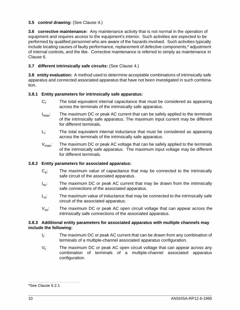
3.5 control drawing: (See Clause 4.)
3.6 corrective maintenance: Any maintenance activity that is not normal in the operation of equipment and requires access to the equipment's interior. Such activities are expected to be performed by qualified personnel who are aware of the hazards involved. Such activities typically include locating causes of faulty performance, replacement of defective components,* adjustment of internal controls, and the like. Corrective maintenance is referred to simply as maintenance in Clause 6.
3.7 different intrinsically safe circuits: (See Clause 4.)
3.8 entity evaluation: A method used to determine acceptable combinations of intrinsically safe apparatus and connected associated apparatus that have not been investigated in such combina-tion.
3.8.1 Entity parameters for intrinsically safe apparatus:
Ci: The total equivalent internal capacitance that must be considered as appearingacross the terminals of the intrinsically safe apparatus.
Imax: The maximum DC or peak AC current that can be safely applied to the terminalsof the intrinsically safe apparatus. The maximum input current may be differentfor different terminals.
Li: The total equivalent internal inductance that must be considered as appearingacross the terminals of the intrinsically safe apparatus.
Vmax: The maximum DC or peak AC voltage that can be safely applied to the terminalsof the intrinsically safe apparatus. The maximum input voltage may be differentfor different terminals.
3.8.2 Entity parameters for associated apparatus:
Ca: The maximum value of capacitance that may be connected to the intrinsicallysafe circuit of the associated apparatus.
Isc: The maximum DC or peak AC current that may be drawn from the intrinsicallysafe connections of the associated apparatus.
La: The maximum value of inductance that may be connected to the intrinsically safecircuit of the associated apparatus.
Voc: The maximum DC or peak AC open circuit voltage that can appear across theintrinsically safe connections of the associated apparatus.
3.8.3 Additional entity parameters for associated apparatus with multiple channels may include the following:
It: The maximum DC or peak AC current that can be drawn from any combination ofterminals of a multiple-channel associated apparatus configuration.
Vt: The maximum DC or peak AC open circuit voltage that can appear across anycombination of terminals of a multiple-channel associated apparatusconfiguration.
*See Clause 6.2.1
10 ANSI/ISA-RP12.6-1995
3.9 galvanic isolation: The transfer of electrical power or signal from one circuit to another by means that do not include a direct electrical connection — e.g., through an isolating transformer or optical coupler.
3.10 hazardous (classified) location: A location where fire or explosion hazards may exist due to the presence of flammable gases or vapors, flammable liquids, combustible dust, or easily ignitible fibers or flyings.
3.11 intrinsic safety: A type of protection in which a portion of the electrical system contains only intrinsically safe equipment (apparatus, circuits, and wiring) that is incapable of causing ignition in the surrounding atmosphere. No single device or wiring is intrinsically safe by itself (except for battery-operated self-contained apparatus such as portable pagers, transceivers, gas detectors, etc., which are specifically designed as intrinsically safe self-contained devices), but is intrinsically safe only when employed in a properly designed intrinsically safe system. This type of protection is referred to by the International Electrotechnical Commission (IEC) as "Ex i." Also see "associated equipment (apparatus)."
3.12 intrinsic safety barrier: A network designed to limit the energy (voltage and current) available to the protected circuit in the hazardous (classified) location, under specified fault condi-tions.
3.13 intrinsic safety ground system: A grounding system that has a dedicated conductor isolated from the power system, except at one point, so that ground currents will not normally flow and is reliably connected to a grounding electrode in accordance with Article 250 of the NEC® or Section 10 of CEC Part I, CSA C22.1.
3.14 intrinsically safe apparatus: (See Clause 4.)
3.15 intrinsically safe circuit: (See Clause 4.)
3.16 intrinsically safe systems: (See Clause 4.)
3.17 labeled: Equipment or materials to which has been attached a label, symbol, or other identifying mark of an organization acceptable to the authority having jurisdiction and concerned with product evaluation, that maintains periodic inspection of production of labeled equipment or materials, and by whose labeling the manufacturer indicates compliance with appropriate standards or performance in a specified manner. (See NEC® reference.)
3.18 listed: Equipment or materials included in a list published by an organization acceptable to the authority having jurisdiction and concerned with product evaluation, that maintains periodic inspection of production of listed equipment or materials, and by whose listing states that the equipment or material meets appropriate designated standards or has been tested and found suitable for use in a specified manner. (See NEC® reference.)
3.19 nonhazardous location: A location not designated as hazardous (classified). The term "unclassified location" is also used in the NEC® .
3.20 qualified person: One familiar with the construction and operation of the equipment and the hazards involved. (See NEC® reference.)
3.21 simple apparatus: A device that will neither generate nor store more than 1.2 V, 0.1 A, 25 mW, or 20 µJ; for example: switches, thermocouples, light-emitting diodes, connectors, and resis-tance temperature devices (RTDs).
ANSI/ISA-RP12.6-1995 11
3.22 wiring drawing: A drawing or other document created by the user based upon the relevant control drawings. The wiring drawing is used by the installer to determine the type, color, and size of the wire used to connect each terminal of the equipment used in the intrinsically safe circuit.
4 Article 504 of the NEC (ANSI/NFPA 70-1993) with explanation
Prior to publication of the 1990 NEC, ANSI/ISA-RP12.6, Installation of Intrinsically Safe Systems for Hazardous (Classified) Locations, was the recommended practice for the installation of intrinsically safe systems. The ISA SP12 committee proposed the addition of Article 504 to provide a more enforceable set of requirements for inspection authorities.
504-1. Scope. This article covers the installation of intrinsically safe (I.S.) apparatus, wiring, and systems for Class I, II, and III locations.
(FPN): For further information, see Installation of Intrinsically Safe Instru-ment Systems in Class I Hazardous Locations, ANSI/ISA RP12.6-1987.
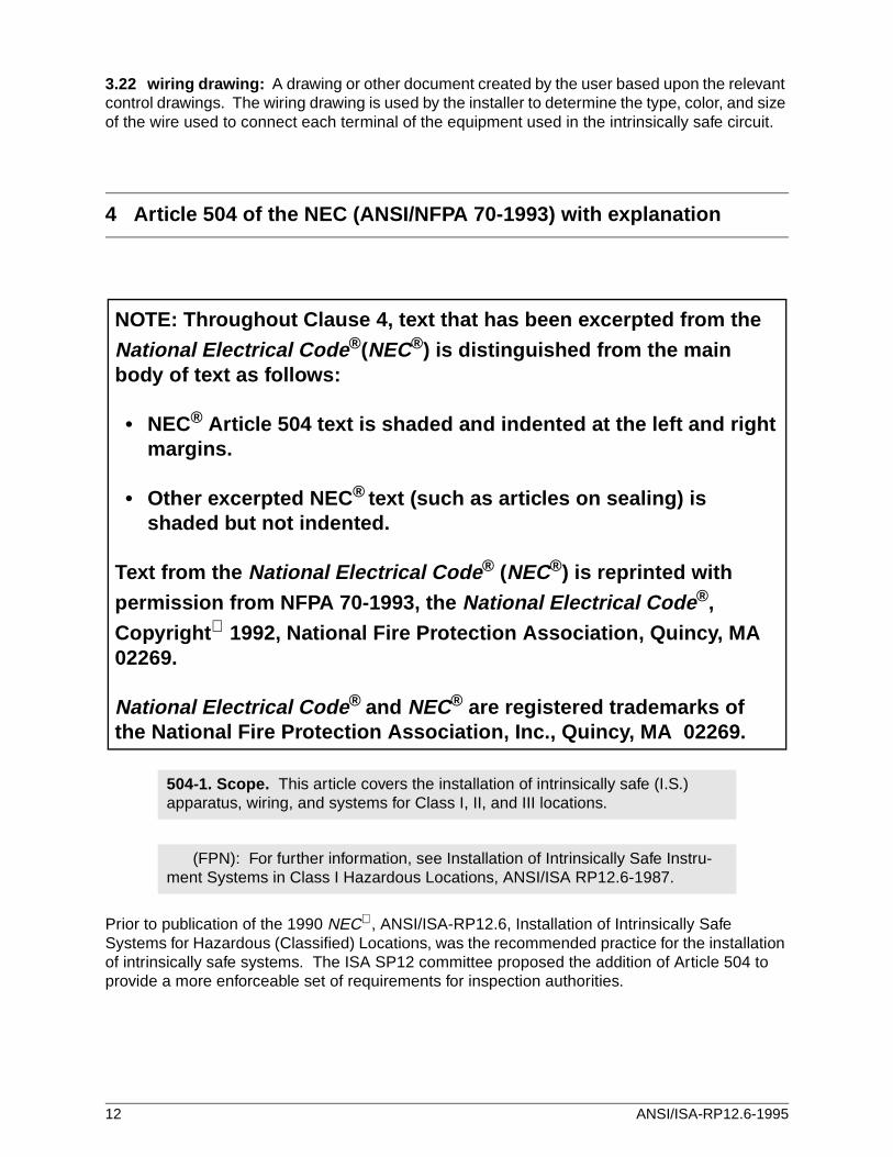
NOTE: Throughout Clause 4, text that has been excerpted from the
National Electrical Code ®(NEC®) is distinguished from the main body of text as follows:
• NEC® Article 504 text is shaded and indented at the left and right margins.
• Other excerpted NEC ® text (such as articles on sealing) isshaded but not indented.
Text from the National Electrical Code ® (NEC®) is reprinted with
permission from NFPA 70-1993, the National Electrical Code ®,
Copyright 1992, National Fire Protection Association, Quincy, MA 02269.
National Electrical Code ® and NEC® are registered trademarks of the National Fire Protection Association, Inc., Quincy, MA 02269.
12 ANSI/ISA-RP12.6-1995
Intrinsic safety barriers are a common form of associated apparatus. These barriers are connected between the intrinsically safe apparatus and the control equipment. Their primary purpose is to limit the energy to the hazardous location under fault conditions. They may also provide isolation, signal conditioning, or both. There are also many types of associated apparatus that normally are not referred to as intrinsic safety barriers, but have energy-limiting circuits suitable for connection directly to intrinsically safe apparatus. An example of this type of associated apparatus is a controller that is not itself intrinsically safe, but has connections for intrinsically safe sensors.
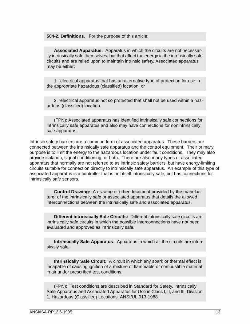
504-2. Definitions . For the purpose of this article:
Associated Apparatus: Apparatus in which the circuits are not necessar-ily intrinsically safe themselves, but that affect the energy in the intrinsically safe circuits and are relied upon to maintain intrinsic safety. Associated apparatus may be either:
1. electrical apparatus that has an alternative type of protection for use in the appropriate hazardous (classified) location, or
2. electrical apparatus not so protected that shall not be used within a haz-ardous (classified) location.
(FPN): Associated apparatus has identified intrinsically safe connections for intrinsically safe apparatus and also may have connections for nonintrinsically safe apparatus.
Control Drawing: A drawing or other document provided by the manufac-turer of the intrinsically safe or associated apparatus that details the allowed interconnections between the intrinsically safe and associated apparatus.
Different Intrinsically Safe Circuits: Different intrinsically safe circuits are intrinsically safe circuits in which the possible interconnections have not been evaluated and approved as intrinsically safe.
Intrinsically Safe Apparatus : Apparatus in which all the circuits are intrin-sically safe.
Intrinsically Safe Circuit: A circuit in which any spark or thermal effect is incapable of causing ignition of a mixture of flammable or combustible material in air under prescribed test conditions.
(FPN): Test conditions are described in Standard for Safety, Intrinsically Safe Apparatus and Associated Apparatus for Use in Class I, II, and III, Division 1, Hazardous (Classified) Locations, ANSI/UL 913-1988.
ANSI/ISA-RP12.6-1995 13
Although intrinsically safe circuits are inherently low energy circuits, they may still be shock hazards because of the operating voltage.
Clause 500-2 provides an exception for intrinsically safe apparatus and wiring from the requirements of Articles 501 through 503 and 510 through 516. All other articles of the Code apply to intrinsically safe wiring, except as exempted by specific articles.
If the rated voltage of the circuit exceeds 60 volts DC or 30 volts AC, the wiring requirements for Class 3 circuits apply. (See NEC® Article 725.)
Other articles may apply, depending on the functional application — e.g., Article 760 for fire protective signaling systems, Article 800 for communications circuits, and Clause 725-49 for cables installed in ducts, plenums, risers, and other air-handling spaces.
Electrical equipment that is listed or labeled by a nationally recognized testing laboratory (NRTL) normally will be accepted by the authority having jurisdiction. The authority having jurisdiction may also accept specialized equipment not listed or labeled by a NRTL, with appropriate technical justification. A written report of the investigation and conclusion should be kept on file, and the markings on the equipment should identify the report.
There are three basic types of control drawings:
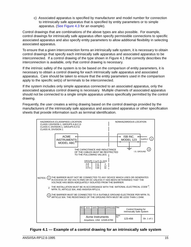
a) Intrinsically safe apparatus and associated apparatus are specified by manufacturer and model number. (See Figure 4.1 for an example).
b) Intrinsically safe apparatus is specified by manufacturer and model number for connection to associated apparatus specified by entity parameters. (See Figure 4.2 for an example).
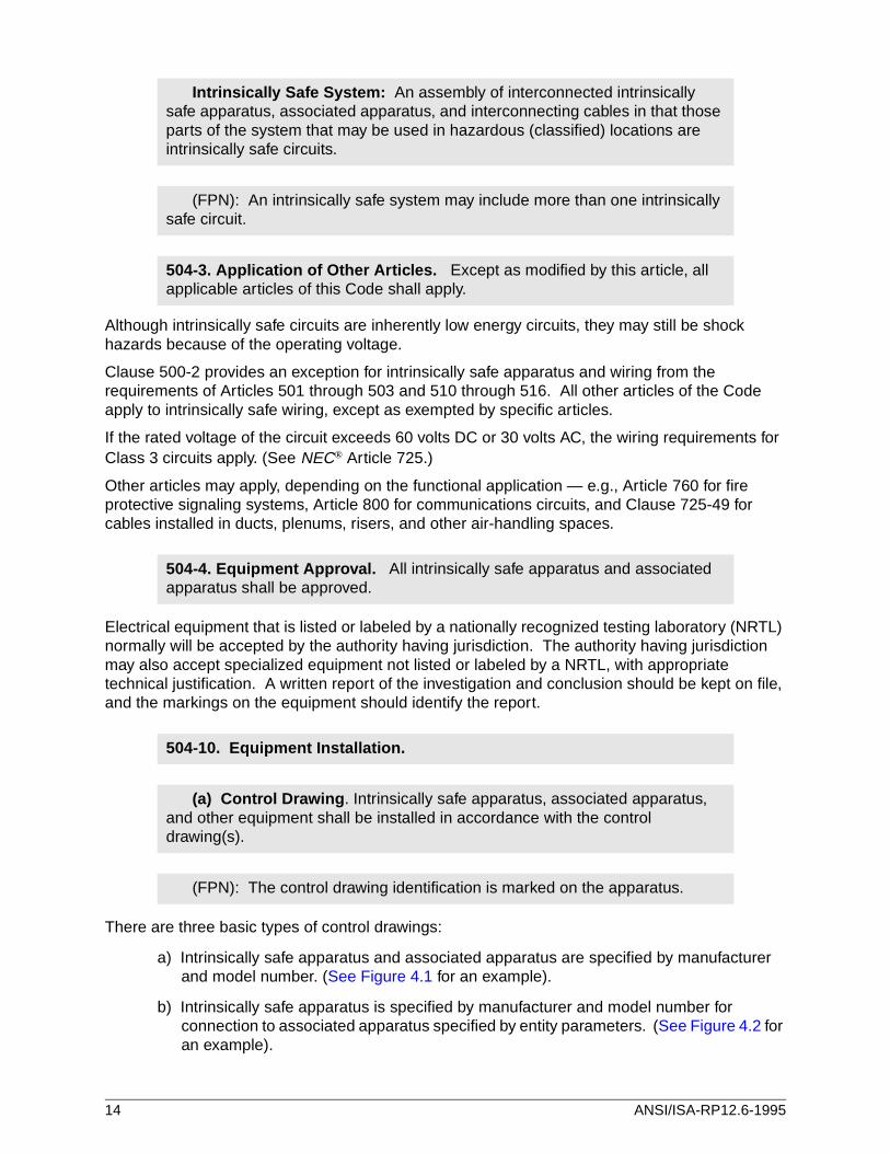
Intrinsically Safe System: An assembly of interconnected intrinsically safe apparatus, associated apparatus, and interconnecting cables in that those parts of the system that may be used in hazardous (classified) locations are intrinsically safe circuits.
(FPN): An intrinsically safe system may include more than one intrinsically safe circuit.
504-3. Application of Other Articles. Except as modified by this article, all applicable articles of this Code shall apply.
504-4. Equipment Approval. All intrinsically safe apparatus and associated apparatus shall be approved.
504-10. Equipment Installation.
(a) Control Drawing . Intrinsically safe apparatus, associated apparatus, and other equipment shall be installed in accordance with the control drawing(s).
(FPN): The control drawing identification is marked on the apparatus.
14 ANSI/ISA-RP12.6-1995
c) Associated apparatus is specified by manufacturer and model number for connection to intrinsically safe apparatus that is specified by entity parameters or to simple apparatus. (See Figure 4.3 for an example).
Control drawings that are combinations of the above types are also possible. For example, control drawings for intrinsically safe apparatus often specify permissible connections to specific associated apparatus and also specify entity parameters to allow additional flexibility in selecting associated apparatus.
To ensure that a given interconnection forms an intrinsically safe system, it is necessary to obtain control drawings that specify each intrinsically safe apparatus and associated apparatus to be interconnected. If a control drawing of the type shown in Figure 4.1 that correctly describes the interconnection is available, only that control drawing is necessary.
If the intrinsic safety of the system is to be based on the comparison of entity parameters, it is necessary to obtain a control drawing for each intrinsically safe apparatus and associated apparatus. Care should be taken to ensure that the entity parameters used in the comparison apply to the specific set(s) of terminals to be interconnected.
If the system includes only simple apparatus connected to an associated apparatus, only the associated apparatus control drawing is necessary. Multiple channels of associated apparatus should not be connected to a single simple apparatus unless specifically permitted by the control drawing.
Frequently, the user creates a wiring drawing based on the control drawings provided by the manufacturers of the intrinsically safe apparatus and associated apparatus or other specification sheets that provide information such as terminal identification.
Figure 4.1 — Example of a control drawing for an intrinsically safe system
REV ECO DATE DRAWN APPROVED
Acme InstrumentsAnywhere, USA 12345-6789
Title
Draw.No.
Sh. 1 of 1
Control Drawing forIntrinsically Safe System
123-456
0.11A,B
C ( F) L (mH)GROUP µ
SUPPLY
I.S. GROUND
ACMEINSTRUMENTS
MODEL ABC
ISB INC.MODEL 123
0.33C,E0.88D,F,G
41232
THE BARRIER MUST NOT BE CONNECTED TO ANY DEVICE WHICH USES OR GENERATESIN EXCESS OF 250 VOLTS RMS OR DC UNLESS IT HAS BEEN DETERMINED THAT THEVOLTAGE HAS BEEN ADEQUATELY ISOLATED FROM THE BARRIER.
THE BARRIER MUST BE CONNECTED TO A SUITABLE GROUND ELECTRODE PER NFPA 70,ARTICLE 504. THE RESISTANCE OF THE GROUND PATH MUST BE LESS THAN 1 OHM.
NONHAZARDOUS LOCATIONHAZARDOUS (CLASSIFIED) LOCATIONCLASS I,DIVISION 1, GROUPS A,B,C,DCLASS II, DIVISION 1, GROUPS E,F,GCLASS III, DIVISION 1
THE CAPACITANCE AND INDUCTANCEOF THE CABLES MUST BE RESTRICTEDTO THE FOLLOWING VALUES:
THE INSTALLATION MUST BE IN ACCORDANCE WITH THE ,NFPA 70, ARTICLE 504, AND ANSI/ISA-RP12.6.
NATIONAL ELECTRICAL CODE ®
NOTES: 1
1
2
3
3
ANSI/ISA-RP12.6-1995 15
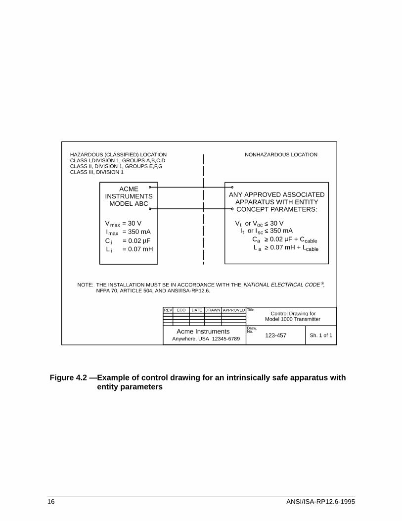
Figure 4.2 —Example of control drawing for an intrinsically safe apparatus withentity parameters
REV ECO DATE DRAWN APPROVED
Acme InstrumentsAnywhere, USA 12345-6789
Title
Draw.No.
Sh. 1 of 1
Control Drawing forModel 1000 Transmitter
123-457
ACMEINSTRUMENTS
MODEL ABC
V = 30 V V or V < 30 VI or I < 350 mA
C > 0.02 F + CL > 0.07 mH + L
I = 350 mAC = 0.02 FL = 0.07 mH
max ocsc
a
a
cable
cable
ttmax
i
i
ANY APPROVED ASSOCIATEDAPPARATUS WITH ENTITYCONCEPT PARAMETERS:
NONHAZARDOUS LOCATIONHAZARDOUS (CLASSIFIED) LOCATIONCLASS I,DIVISION 1, GROUPS A,B,C,DCLASS II, DIVISION 1, GROUPS E,F,GCLASS III, DIVISION 1
THE INSTALLATION MUST BE IN ACCORDANCE WITH THE ,NFPA 70, ARTICLE 504, AND ANSI/ISA-RP12.6.
NATIONAL ELECTRICAL CODE ®NOTE:
µ µ
16 ANSI/ISA-RP12.6-1995
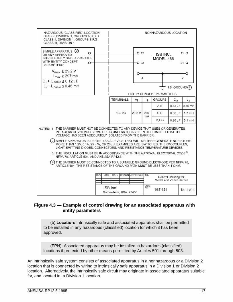
Figure 4.3 — Example of control drawing for an associated apparatus with entity parameters
An intrinsically safe system consists of associated apparatus in a nonhazardous or a Division 2 location that is connected by wiring to intrinsically safe apparatus in a Division 1 or Division 2 location. Alternatively, the intrinsically safe circuit may originate in associated apparatus suitable for, and located in, a Division 1 location.
(b) Location: Intrinsically safe and associated apparatus shall be permitted to be installed in any hazardous (classified) location for which it has been approved.
(FPN): Associated apparatus may be installed in hazardous (classified) locations if protected by other means permitted by Articles 501 through 503.
ANSI/ISA-RP12.6-1995 17
Equipment that has been approved for a Division 1 location may be used in a Division 2 location of the same class and group. (See paragraph 500-3 (a) of the NEC® .)
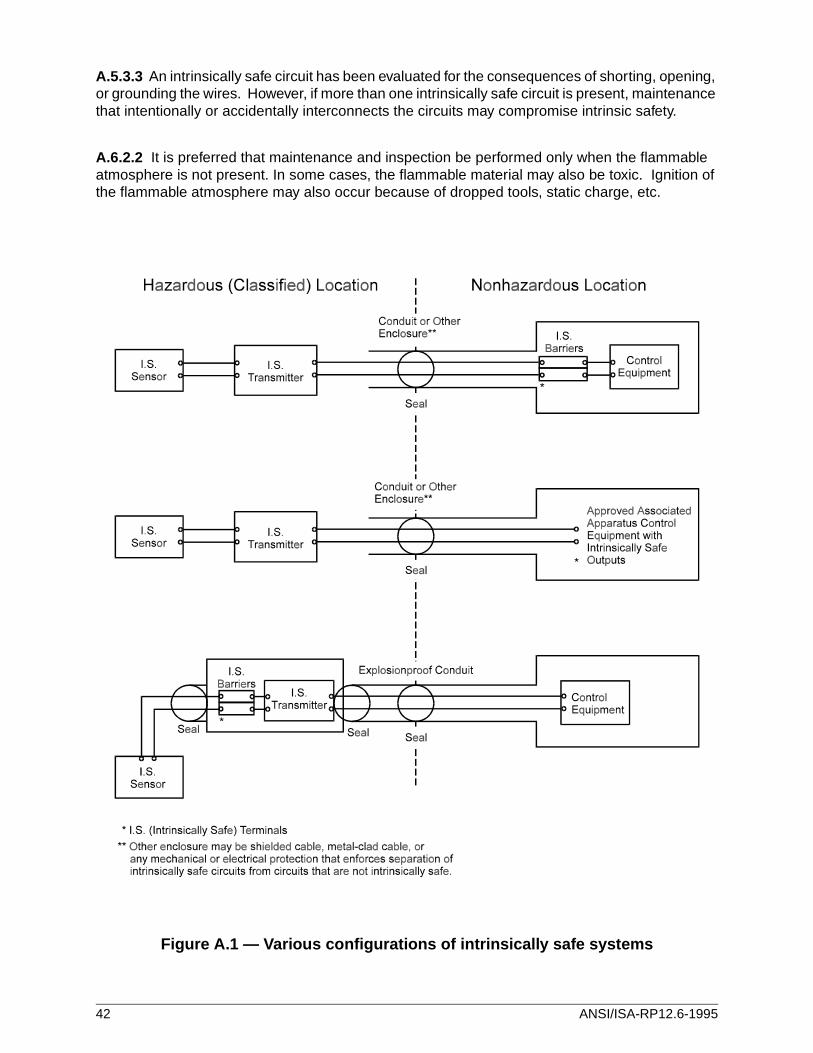
Some examples of intrinsically safe systems are given in Figure A-1.
Intrinsically safe apparatus should be provided with an enclosure that is suitable for the environmental conditions to which it will be exposed (such as temperature, moisture, and corrosion).
Intrinsically safe circuits need not comply, for example, with Articles 501 through 503 and 510 through 516 of the NEC® (1993) or Rules 18-100 through 18-130 of the CEC (1990) and, in general, may be wired in the same manner as comparable circuits intended for use in nonhazardous locations. Examples are PLTC cable in cable trays, nonmetallic cables, and communication cables. Since the energy in an intrinsically safe circuit is inherently limited, no additional overcurrent protection is required in such circuits.
Additional precautions should be taken to provide mechanical protection in applications involving vibration, motion, impacts, etc.
When intrinsically safe wiring may be exposed to disturbing electromagnetic fields, suitable attention should be given to twisting or shielding conductors, or other methods to prevent the energy level of the intrinsically safe wiring from becoming ignition-capable.
General-purpose enclosures shall be permitted for intrinsically safe apparatus.
504-20. Wiring Methods. Intrinsically safe apparatus and wiring shall be per-mitted to be installed using any of the wiring methods suitable for unclassified locations. Sealing shall be as provided in 504-70, and separation shall be as provided in 504-30.
504-30. Separation of Intrinsically Safe Conductors.
(a) From Nonintrinsically Safe Circuit Conductors .
(1) Open wiring. Conductors and cables of intrinsically safe circuits not in raceways or cable trays shall be separated at least 2 inches (50 mm) and secured from conductors and cables of any nonintrinsically safe circuits.
Exception: Where either: (1) all of the intrinsically safe circuit conductors are in Type MI, MC, or SNM cables or (2) all of the nonintrinsically safe circuit conductors are in raceways or Type MI, MC, or SNM cables where the sheath-ing or cladding is capable of carrying fault current to ground.
(2) In raceways, cable trays, and cables. Conductors of intrinsically safe circuits shall not be placed in any raceway, cable tray, or cable with conduc-tors of any nonintrinsically safe circuit.
18 ANSI/ISA-RP12.6-1995
Braided or aluminum/polyester shielding is not considered suitable for a grounded metal partition. Cable jackets normally are not considered suitable for an insulating partition.
Care shall be taken in the layout of terminals and the wiring methods used to prevent contact between intrinsically safe and nonintrinsically safe circuits. Some layouts — e.g., when terminals arranged one above another — do not provide adequate separation if a wire should become disconnected. In these cases, additional precautions (such as tie-downs) are necessary.
Clearance between ungrounded terminals and grounded metal should be at least 3 mm(0.125 in.).
A partition may be used to segregate terminals and should extend close enough to the enclosure walls to effectively separate the wiring on either side of the partition. Alternatively, the partition need only extend far enough beyond the terminals to provide 50 mm (2 in.) spacing between
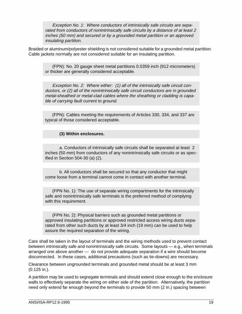
Exception No. 1: Where conductors of intrinsically safe circuits are sepa-rated from conductors of nonintrinsically safe circuits by a distance of at least 2 inches (50 mm) and secured or by a grounded metal partition or an approved insulating partition.
(FPN): No. 20 gauge sheet metal partitions 0.0359 inch (912 micrometers) or thicker are generally considered acceptable.
Exception No. 2: Where either: (1) all of the intrinsically safe circuit con-ductors, or (2) all of the nonintrinsically safe circuit conductors are in grounded metal-sheathed or metal-clad cables where the sheathing or cladding is capa-ble of carrying fault current to ground.
(FPN): Cables meeting the requirements of Articles 330, 334, and 337 are typical of those considered acceptable.
(3) Within enclosures.
a. Conductors of intrinsically safe circuits shall be separated at least 2 inches (50 mm) from conductors of any nonintrinsically safe circuits or as spec-ified in Section 504-30 (a) (2).
b. All conductors shall be secured so that any conductor that might come loose from a terminal cannot come in contact with another terminal.
(FPN No. 1): The use of separate wiring compartments for the intrinsically safe and nonintrinsically safe terminals is the preferred method of complying with this requirement.
(FPN No. 2): Physical barriers such as grounded metal partitions or approved insulating partitions or approved restricted access wiring ducts sepa-rated from other such ducts by at least 3/4 inch (19 mm) can be used to help assure the required separation of the wiring.
ANSI/ISA-RP12.6-1995 19
intrinsically safe and nonintrinsically safe terminals if the wiring is secured to maintain the required separation.
When several devices having both intrinsically safe and nonintrinsically safe terminals are mounted in the same enclosure, attention must be given to the separation of circuits. An acceptable method of separation is shown in Figure A-2. Separate wireways are often used to provide greater assurance that separation of wiring will be maintained. Wire lacing, wire ties, or equivalent fasteners are also acceptable methods of maintaining the 50 mm (2 in.) separation.
Plug-and-socket connectors used to connect intrinsically safe circuits in a nonhazardous location either should not be interchangeable with any other plugs or sockets or should be identified in a way that minimizes the possibility of such interchange.
Clearance between terminals for the connection of different intrinsically safe circuits should be at least 6 mm (0.25 in).
The integrity of a shunt diode intrinsic safety barrier depends on the effective shunting of the ignition-capable electrical current back to the source (to ground).
It is the intent of the following recommendations to ensure that the methods used to connect barriers to ground provide a high integrity, low resistance return path to the source of the fault current. A separate insulated connection to a grounding electrode will minimize fault currents from other equipment elevating the I.S. ground. Careful consideration should be given to the grounding electrode system(s) to which potential sources of supply and intrinsically safe apparatus are connected. This will enable a determination of whether shunt diode barriers are appropriate (see Figure 4.7) and, if so, selection of a grounding electrode.
Exception: The equipment grounding conductor may be used as the intrinsic safetygrounding conductor only if potential ground fault current from other equipment that is
(b) From Different Intrinsically Safe Circuit Conductors. Different intrin-sically safe circuits shall be in separate cables or shall be separated from each other by one of the following means:
(1) The conductors of each circuit are within a grounded metal shield;
(2) The conductors of each circuit have insulation with a minimum thick-ness of 0.01 inch (254 micrometers).
Exception: Unless otherwise approved.
504-50 Grounding.
(a) Intrinsically Safe Apparatus, Associated Apparatus, and Raceways. Intrinsically safe apparatus, associated apparatus, cable shields, enclosures and raceways, if of metal, shall be grounded.
(FPN): Supplementary bonding to the grounding electrode may be needed for some associated apparatus, -- e.g., zener diode barriers, if specified in the control drawing. See Installation of Intrinsically Safe Instrument Systems in Class I Hazardous Locations, ANSI/ISA RP12.6-1987.
20 ANSI/ISA-RP12.6-1995
sharing the AC grounding conductor will not cause an unsafe voltage differentialbetween the grounding electrode and a grounded conductor of an intrinsically safecircuit. Examples of installations not requiring a separate intrinsic safety groundingconductor may include flowmeters with intrinsically safe transducers, consoles withintrinsically safe keyboards, and recorders with intrinsically safe inputs where there isan equipotential bond between the barrier ground and grounded metal parts that theintrinsically safe circuit may contact.
The barrier grounding terminal must be connected to the grounding electrode. Where there are multiple barriers, the individual grounding terminals may be collected at a common point such as a barrier bus (see Figures 4.4 through 4.6). The common point or the grounding terminal on a single barrier must be connected to the grounding electrode using an insulated conductor no smaller than 12 AWG (American Wire Gauge). The wires between individual barriers and the common point may be smaller than 12 AWG. The conductor to the grounding electrode should be identified at both ends to differentiate it from other ground conductors. The conductor must be protected from damage as required by NEC® 250-95(c).
All grounding path connections should be secure, permanent, visible, and accessible. The grounding path resistance from the farthest barrier to the grounding electrode should not exceed 1 ohm.
More than one barrier bus may use the same grounding conductor(s), provided the buses are interconnected in such a way that disconnection of one barrier bus does not result in loss of ground to the other buses.
Figure 4.4 shows a grounding system in which a separate intrinsic safety ground conductor is connected directly between the barrier bus and the grounding electrode.
Figure 4.5 shows an alternate grounding system in which the separate intrinsic safety ground conductor is connected between the supply common bus and the grounding electrode.
Figure 4.6 shows an alternate grounding system in which the supply common bus and the barrier bus are connected to a separate master barrier bus bar that is used to interconnect the barrier buses from several cabinets.
ANSI/ISA-RP12.6-1995 21
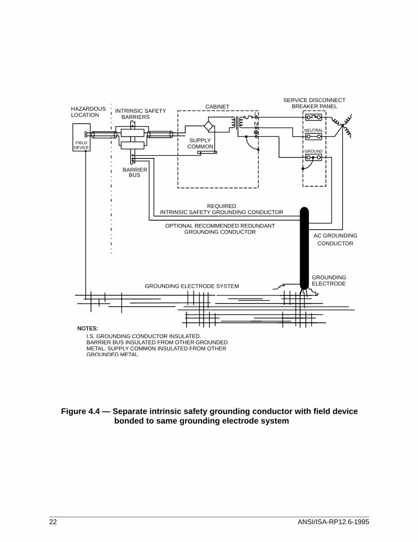
Figure 4.4 — Separate intrinsic safety grounding conductor with field devicebonded to same grounding electrode system
NEUTRAL
GROUND
L
N
CABINET
SUPPLYCOMMON
HAZARDOUSLOCATION
FIELDDEVICE
INTRINSIC SAFETYBARRIERS
BARRIERBUS
SERVICE DISCONNECTBREAKER PANEL
REQUIREDINTRINSIC SAFETY GROUNDING CONDUCTOR
OPTIONAL RECOMMENDED REDUNDANTGROUNDING CONDUCTOR
AC GROUNDINGCONDUCTOR
GROUNDING ELECTRODE SYSTEM
GROUNDING
NOTES:NOTES:I.S. GROUNDING CONDUCTOR INSULATED.BARRIER BUS INSULATED FROM OTHER GROUNDEDMETAL. SUPPLY COMMON INSULATED FROM OTHERGROUNDED METAL.
ELECTRODE
22 ANSI/ISA-RP12.6-1995
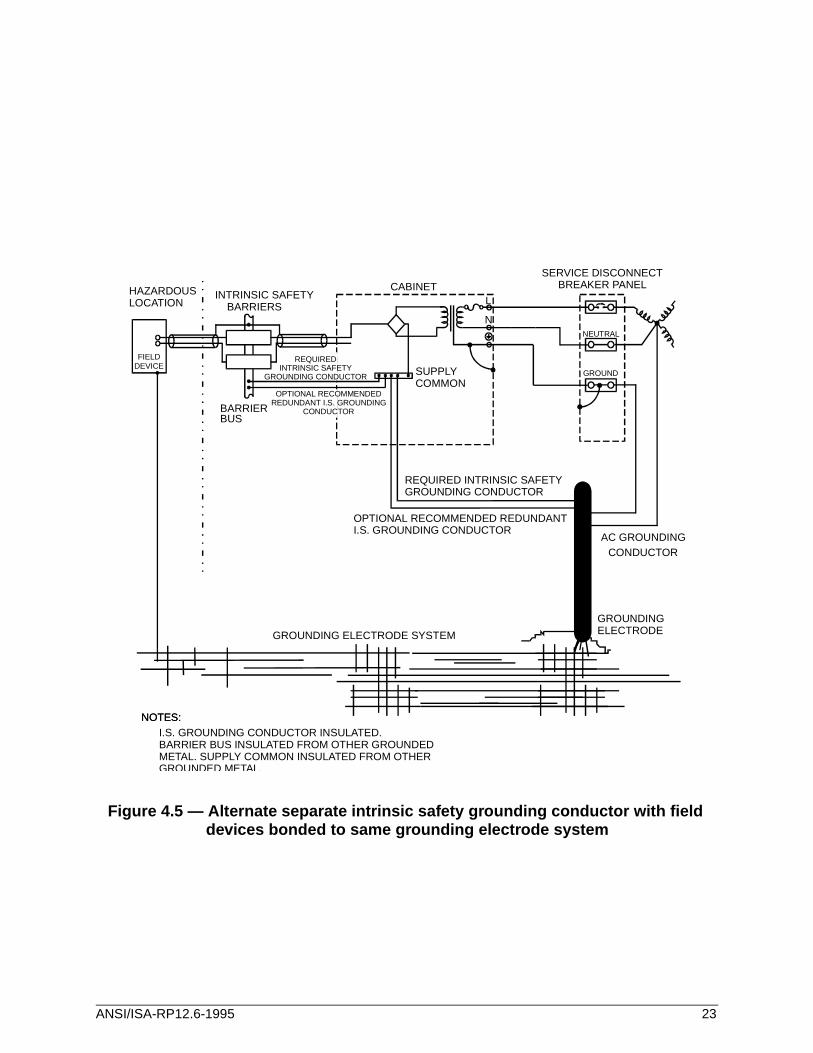
Figure 4.5 — Alternate separate intrinsic safety grounding conductor with fielddevices bonded to same grounding electrode system
NEUTRAL
GROUND
L
N
CABINET
SUPPLYCOMMON
HAZARDOUSLOCATION
FIELDDEVICE
INTRINSIC SAFETYBARRIERS
BARRIERBUS
SERVICE DISCONNECTBREAKER PANEL
REQUIRED INTRINSIC SAFETYGROUNDING CONDUCTOR
OPTIONAL RECOMMENDED REDUNDANTI.S. GROUNDING CONDUCTOR
AC GROUNDINGCONDUCTOR
GROUNDING ELECTRODE SYSTEM
GROUNDING
NOTES:NOTES:I.S. GROUNDING CONDUCTOR INSULATED.BARRIER BUS INSULATED FROM OTHER GROUNDEDMETAL. SUPPLY COMMON INSULATED FROM OTHERGROUNDED METAL.
ELECTRODE
REQUIREDINTRINSIC SAFETY
GROUNDING CONDUCTOR
OPTIONAL RECOMMENDEDREDUNDANT I.S. GROUNDING
CONDUCTOR
ANSI/ISA-RP12.6-1995 23
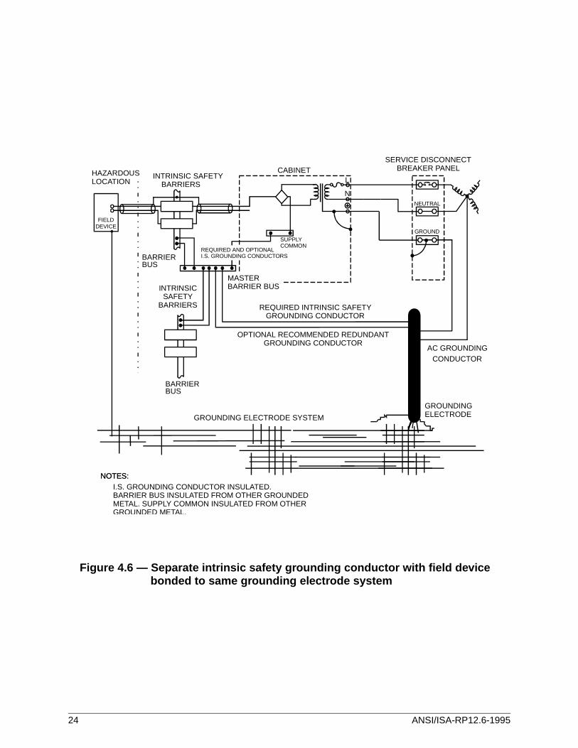
Figure 4.6 — Separate intrinsic safety grounding conductor with field device bonded to same grounding electrode system
NEUTRAL
GROUND
L
N
CABINET
SUPPLYCOMMON
HAZARDOUSLOCATION
FIELDDEVICE
INTRINSIC SAFETYBARRIERS
BARRIERBUS
INTRINSICSAFETY
BARRIERS
BARRIERBUS
SERVICE DISCONNECTBREAKER PANEL
REQUIRED INTRINSIC SAFETYGROUNDING CONDUCTOR
OPTIONAL RECOMMENDED REDUNDANTGROUNDING CONDUCTOR
AC GROUNDINGCONDUCTOR
GROUNDING ELECTRODE SYSTEM
GROUNDING
NOTES:NOTES:I.S. GROUNDING CONDUCTOR INSULATED.BARRIER BUS INSULATED FROM OTHER GROUNDEDMETAL. SUPPLY COMMON INSULATED FROM OTHERGROUNDED METAL.
ELECTRODE
MASTERBARRIER BUS
REQUIRED AND OPTIONALI.S. GROUNDING CONDUCTORS
24 ANSI/ISA-RP12.6-1995
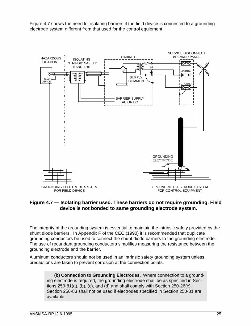
Figure 4.7 shows the need for isolating barriers if the field device is connected to a grounding electrode system different from that used for the control equipment.
Figure 4.7 — Isolating barrier used. These barriers do not require grounding. Fielddevice is not bonded to same grounding electrode system.
The integrity of the grounding system is essential to maintain the intrinsic safety provided by the shunt diode barriers. In Appendix F of the CEC (1990) it is recommended that duplicate grounding conductors be used to connect the shunt diode barriers to the grounding electrode. The use of redundant grounding conductors simplifies measuring the resistance between the grounding electrode and the barrier.
Aluminum conductors should not be used in an intrinsic safety grounding system unless precautions are taken to prevent corrosion at the connection points.
(b) Connection to Grounding Electrodes. Where connection to a ground-ing electrode is required, the grounding electrode shall be as specified in Sec-tions 250-81(a), (b), (c), and (d) and shall comply with Section 250-26(c). Section 250-83 shall not be used if electrodes specified in Section 250-81 are available.
NEUTRAL
GROUND
L
N
CABINET
SUPPLYCOMMON
BARRIER SUPPLYAC OR DC
HAZARDOUSLOCATION
FIELDDEVICE
ISOLATINGINTRINSIC SAFETY
BARRIERS
SERVICE DISCONNECTBREAKER PANEL
GROUNDING ELECTRODE SYSTEMFOR FIELD DEVICE
GROUNDING ELECTRODE SYSTEMFOR CONTROL EQUIPMENT
GROUNDINGELECTRODE
ANSI/ISA-RP12.6-1995 25
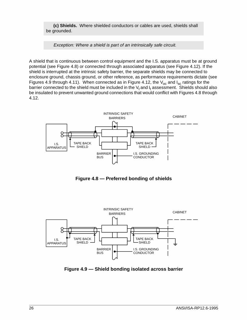
A shield that is continuous between control equipment and the I.S. apparatus must be at ground potential (see Figure 4.8) or connected through associated apparatus (see Figure 4.12). If the shield is interrupted at the intrinsic safety barrier, the separate shields may be connected to enclosure ground, chassis ground, or other reference, as performance requirements dictate (see Figures 4.9 through 4.11). When connected as in Figure 4.12, the Voc and Isc ratings for the barrier connected to the shield must be included in the Vt and It assessment. Shields should also be insulated to prevent unwanted ground connections that would conflict with Figures 4.8 through 4.12.
Figure 4.8 — Preferred bonding of shields
Figure 4.9 — Shield bonding isolated across barrier
(c) Shields. Where shielded conductors or cables are used, shields shall be grounded.
Exception: Where a shield is part of an intrinsically safe circuit.
CABINETINTRINSIC SAFETY
BARRIERS
BARRIERBUS
I.S. GROUNDINGCONDUCTOR
I.S.APPARATUS
TAPE BACKSHIELD
TAPE BACKSHIELD
CABINETINTRINSIC SAFETY
BARRIERS
BARRIERBUS
I.S. GROUNDINGCONDUCTOR
I.S.APPARATUS
TAPE BACKSHIELD
TAPE BACKSHIELD
26 ANSI/ISA-RP12.6-1995
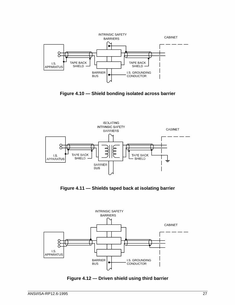
Figure 4.10 — Shield bonding isolated across barrier
Figure 4.11 — Shields taped back at isolating barrier
Figure 4.12 — Driven shield using third barrier
CABINETINTRINSIC SAFETY
BARRIERS
BARRIERBUS
I.S. GROUNDINGCONDUCTOR
I.S.APPARATUS
TAPE BACKSHIELD
TAPE BACKSHIELD
CABINET
INTRINSIC SAFETYBARRIERS
BARRIERBUS
I.S. GROUNDINGCONDUCTOR
I.S.APPARATUS
ANSI/ISA-RP12.6-1995 27
When metal conduit is not used for intrinsically safe circuits, bonding of exposed metal parts must be accomplished through other means, such as bonding conductors.
It is necessary that all raceways, enclosures, etc. located between a hazardous location and the point of grounding are bonded in a fashion similar to the raceways utilized in the hazardous location. The main purpose of the bonding is to provide a low resistance path to ground, to prevent sparking or arcing, in the hazardous location. For example, during a ground fault condition in the associated apparatus enclosure or in the raceway between the enclosure and the power source, this raceway is expected to carry the fault current to its source until the overcurrent device functions to clear the fault. However, if this raceway bonding is a greater resistance than the bonding in the hazardous location, the fault current will flow in the hazardous location. During this interval, some of the current will try to flow through incidental contacts (piping, metal beams,
504-60. Bonding.
(a) Hazardous Locations. In hazardous (classified) locations, intrinsically safe apparatus shall be bonded in the hazardous (classified) location in accor-dance with Section 250-78.
250-78 Bonding in Hazardous (Classified) Locations. Regardless of the voltage of the electrical system, the electrical continuity of noncurrent-carrying metal parts of equipment, raceways, and other enclosures...shall be assured by any of the methods specified for ser-vices in Section 250-72 (b) through (e) that are approved for the wiring method used.
250-72 (b) Threaded Connections. Connections utilizing threaded couplings or threaded bosses on enclosures shall be made up wrenchtight where rigid metal conduit or intermediate metal conduit is involved.
250-72 (c) Threadless Couplings and Connectors. Threadless couplings and connectors made up tight for rigid metal conduit, intermediate metal conduit, and electrical metallic tubing. Stan-dard locknuts or bushings shall not be used for the bonding required by this section.
250-72 (d) Bonding Jumpers. Bonding jumpers meeting the other requirements of this article shall be used around concentric or eccentric knockouts that are punched or otherwise formed so as to impair the electrical connection to ground.
250-72 (e) Other Devices. Other approved devices, such as bonding-type locknuts and bushings.
(b) Nonhazardous Locations . In nonhazardous locations where metal raceways are used for intrinsically safe system wiring in hazardous locations, associated apparatus shall be bonded in accordance with Sections 501-16(a), 502-16(a) or 503-16(a), as applicable.
28 ANSI/ISA-RP12.6-1995
etc.) Since those incidental contacts, in the hazardous location, may not be able to handle such fault currents, a spark, arc, or heated metal could result.
504-70. Sealing. Conduits and cables that are required to be sealed by Clauses 501-5 and 502-5 shall be sealed to minimize the passage of gases, vapors or dust.
Exception: Seals are not required for enclosures that contain only intrinsi-cally safe apparatus except as required by section 501-5(f)(3).
(FPN): It is not the intent of this section to require an explosionproof seal.
The following sections pertain to sealing and drainage of intrinsically safe systems. If an explosionproof installation is required, explosionproof fittings are required for the intrinsically safe circuits leaving the enclosure.
501-5 Sealing and Drainage . Seals in conduit and cable systems shall comply with (a) through (f) below. Sealing compound shall be of a type approved for the conditions and use. Sealing compound shall be used in Type MI cable termination fittings to exclude moisture and other fluids from the cable insulation.
(FPN No. 1): Seals are provided in conduit and cable systems to minimize the passage of gases and vapors and prevent the passage of flames from one portion of the electrical installa-tion to another through the conduit. Such communication through Type MI cable is inherently prevented by construction of the cable. Unless specifically designed and tested for the pur-pose, conduit and cable seals are not intended to prevent the passage of liquids, gases, or vapors at a continuous pressure differential across the seal. Even at differences in pressure across the seal equivalent to a few inches of water, there may be a slow passage of gas or vapor through a seal and through conductors passing through the seal. See Clause 501-5(e)(2). Temperature extremes and highly corrosive liquids and vapors can affect the ability of seals to perform their intended function. See Clause 501-5(c)(2).
(FPN No. 2): Gas or vapor leakage and propagation of flames may occur through the inter-stices between the strands of standard stranded conductors larger than No. 2. Special con-ductor constructions — e.g., compacted strands or sealing of the individual strands, are means of reducing leakage and preventing the propagation of flames.
(a) Conduit Seals, Class I, Division 1. In Class I, Division 1 locations, conduit seals shall be located as follows:
ANSI/ISA-RP12.6-1995 29
Paragraphs 501-5(a)(1), 501-5(a)(2), and 501-5(a)(3) do not apply to equipment containing only intrinsically safe circuits.
Paragraph 501-5 (b)(1) does not apply to intrinsically safe apparatus.
(4) In each conduit run leaving the Class I, Division 1 location. The sealing fitting shall be per-mitted on either side of the boundary of such location but shall be so designed and installed to minimize the amount of gas or vapor that may have entered the conduit system with the Divi-sion 1 location from being communicated to the conduit beyond the seal. There shall be no union, coupling, box or fitting in the conduit between the sealing fitting and the point at which the conduit leaves the Division 1 location.
Exception: Metal conduit containing no unions, couplings, boxes, or fittings that passes com-pletely through a Class I, Division 1 location with no fittings less than 12 inches (305 mm) beyond each boundary shall not be required to be sealed if the termination points of the unbro-ken conduit are in unclassified locations.
(b) Conduit Seals, Class I, Division 2. In Class I, Division 2 locations, conduit seals shall be located as follows:
(2) In each conduit run passing from a Class I, Division 2 location into an unclassified location. The sealing fitting shall be permitted on either side of the boundary of such a location but shall be so designed and installed to minimize the amount of gas or vapor that may have entered the conduit system within the Division 2 location from being communicated to the conduit beyond the seal. Rigid metal conduit or threaded steel intermediate metal conduit shall be used between the sealing fitting and the point at which the conduit leaves the Division 2 loca-tion, and a threaded connection shall be used at the sealing fitting. There shall be no union, coupling, box, or fitting in the conduit between the sealing fitting and the point at which the con-duit leaves the Division 2 location.
Exception No. 1: Metal conduit containing no unions, couplings, boxes, or fittings that passes completely through a Class I, Division 2 location with no fittings less than 12 inches (305 mm) beyond each boundary shall not be required to be sealed if the termination points of the unbro-ken conduit are in unclassified locations.
Exception No. 2: Conduit systems terminating at an outdoor unclassified location where a wir-ing method transition is made to cable tray, cablebus, ventilated busway, TYPE MI cable, or open wiring shall not be required to be sealed where passing from the Class I, Division 2 loca-tion into the unclassified area. The conduits shall not terminate at an enclosure containing an ignition source.
(c) Class I, Divisions 1 and 2. Where required, seals in Class I, Division 1 and 2 locations shall comply with the following:
(1) Fittings. Enclosures for connections or equipment shall be provided with an approved integral means for sealing, or sealing fittings approved for Class I locations shall be used. Sealing fittings shall be accessible.
30 ANSI/ISA-RP12.6-1995
Cables not installed in conduit are permitted for intrinsically safe circuits, but the above rules do not cover the sealing requirements. Refer to the NEC® or CEC, as applicable, for Division 2 requirements for sealing cables not in conduit.
(2) Compound. Sealing compound shall be approved and shall provide a seal against pas-sage of gas or vapors through the seal fitting, shall not be affected by the surrounding atmo-sphere or liquids and shall not have a melting point of less than 93°C (200°F).
(3) Thickness of compounds. In a completed seal, the minimum thickness of the sealing compound shall not be less than the trade size of the conduit and in no case less than 5/8 inch (16 mm).
(4) Splices and taps. Splices and taps shall not be made in fittings intended only for sealing with compound, nor shall other fittings in which splices or taps are made be filled with com-pound.
(5) Assemblies . In an assembly where equipment that may produce arcs, sparks, or high temperatures is located in a compartment separate from the compartment containing splices or taps, and an integral seal is provided where conductors pass from one compartment to the other, the entire assembly shall be approved for Class I locations. Seals in conduit connec-tions to the compartment containing splices or taps shall be provided in Class I, Division 1 locations where required by (a)(2) above.
(d) Cable seals, Class I, Division 1. In Class I, Division 1 locations each multiconductor cable in conduit shall be considered as a single conductor if the cable is incapable of transmit-ting gases or vapors through the cable core. These cables shall be sealed in accordance with (a) above.
Cable with a gas/vapor-tight continuous sheath capable of transmitting gases or vapors through the cable core shall be sealed in the Division 1 location after removing the jacket and any other coverings so that the sealing compound will surround each individual insulated con-ductor and the outer jacket.
Exception: Multiconductor cables with a gas/vapor-tight continuous sheath capable of transmit-ting gases or vapors through the cable core shall be permitted to be considered as a single conductor by sealing the cable in the conduit within 18 inches (457 mm) of the enclosure and the cable end within the enclosure by an approved means to prevent the entrance of gases or vapors or propagation of flame into the cable core, or by other approved methods.
(e) Cable Seals, Class I, Division 2. In Class I, Division 2 locations, cable seals shall be located as follows:
ANSI/ISA-RP12.6-1995 31
Paragraph 501-5 (e)(1) does not apply to intrinsically safe apparatus.
(2) Cables with a gas/vapor-tight continuous sheath and which will not transmit gases or vapors through the cable core in excess of the quantity permitted for seal fittings shall not be required to be sealed... The minimum length of such cable run shall not be less than that length which limits gas or vapor flow through the cable core to the rate permitted for seal fit-tings [0.007 cubic feet per hour (198 cubic centimeters per hour) of air at a pressure of 6 inches of water (1493 pascals).]
(3) Cables with a gas/vapor-tight continuous sheath capable of transmitting gases or vapors through the cable core shall not be required to be sealed..., unless the cable is attached to pro-cess equipment or devices that may cause a pressure in excess of 6 inches (1493 pascals) of water to be exerted at a cable end, in which case a seal, barrier, or other means shall be pro-vided to prevent migration of flammables into an unclassified area.
Exception: Cables with an unbroken gas/vapor-tight continuous sheath shall be permitted to pass through a Class I, Division 2 location without seals.
(4) Cables that do not have a gas/vapor-tight continuous sheath shall be sealed at the bound-ary of the Division 2 and unclassified location in such a manner as to minimize the passage of gases or vapors into an unclassified location.
(FPN): The sheath mentioned in (d) and (e) above may be either metal or a nonmetallic mate-rial.
(f) Drainage.
(1) Control Equipment. Where there is a probability that liquid or other condensed vapor may be trapped within enclosures for control equipment or at any point in the raceway system, approved means shall be provided to prevent accumulation or to permit periodic draining of such liquid or condensed vapor.
(2) Motors and Generators. Where the authority having jurisdiction judges that there is a probability that liquid or condensed vapor may accumulate within motors or generators, joints and conduit systems shall be arranged to minimize entrance of liquid. If means to prevent accumulation or to permit periodic draining are judged necessary, such means shall be pro-vided at the time of manufacture and shall be considered an integral part of the machine.
(3) Canned Pumps, Process or Service Connections, Etc. For canned pumps, process or service connections for flow, pressure, or analysis measurement, etc., that depend upon a sin-gle compression seal, diaphragm or tube to prevent flammable or combustible fluids from entering the electrical conduit system, an additional approved seal, barrier, or other means shall be provided to prevent the flammable or combustible fluid from entering the conduit sys-tem beyond the additional devices or means, if the primary seal fails.
32 ANSI/ISA-RP12.6-1995
See Figure 4.13 for an example of sealing conduit that contains intrinsically safe circuits.
The additional approved seal or barrier and the interconnecting enclosure shall meet the tem-perature and pressure conditions to which they will be subjected upon failure of the primary seal, unless other approved means are provided to accomplish the purpose above.
Drains, vents, or other devices shall be provided so that primary seal leakage will be obvious.
(FPN): See also the last paragraph of Section 500-5(b) and Fine Print Notes to Section 501-5.
502-5 Sealing, Class II, Divisions 1 and 2. Where a raceway provides communication between an enclosure that is required to be dust-ignitionproof and one that is not, suitable means shall be provided to prevent the entrance of dust into the dust-ignitionproof enclosure through the raceway. One of the following means shall be permitted: (1) a permanent and effective seal; (2) a horizontal raceway not less than 10 feet (3.05 m) long; or (3) a vertical raceway not less than 5 feet (1.52 m) long and extending downward from the dust-ignitionproof enclosure.
Where a raceway provides communication between an enclosure that is required to be dust-ignitionproof and an enclosure in an unclassified location, seals shall not be required.
Sealing fittings shall be accessible.
Exception: Seals are not required for enclosures that contain only intrinsi-cally safe apparatus except as required by Section 501-5(f)(3).
(FPN): It is not the intent of this section to require an explosionproof seal.
504-80 Identification. Labels required by this section shall be suitable for the environment where they are installed with consideration given to exposure to chemicals and sunlight.
(a) Terminals. Intrinsically safe circuits shall be identified at terminal and junction locations in a manner that will prevent unintentional interference with the circuits during testing and servicing.
(b) Wiring. Raceways, cable trays, and open wiring for intrinsically safe sys-tem wiring shall be identified with permanently affixed labels with the wording "Intrinsic Safety Wiring" or equivalent. The labels shall be so located as to be visible after installation and placed so that they may be readily traced through the entire length of the installation. Spacing between labels shall not be more than 25 feet (7.62 m).
Exception: Circuits run underground shall be permitted to be identified where they become accessible after emergence from the ground.
ANSI/ISA-RP12.6-1995 33
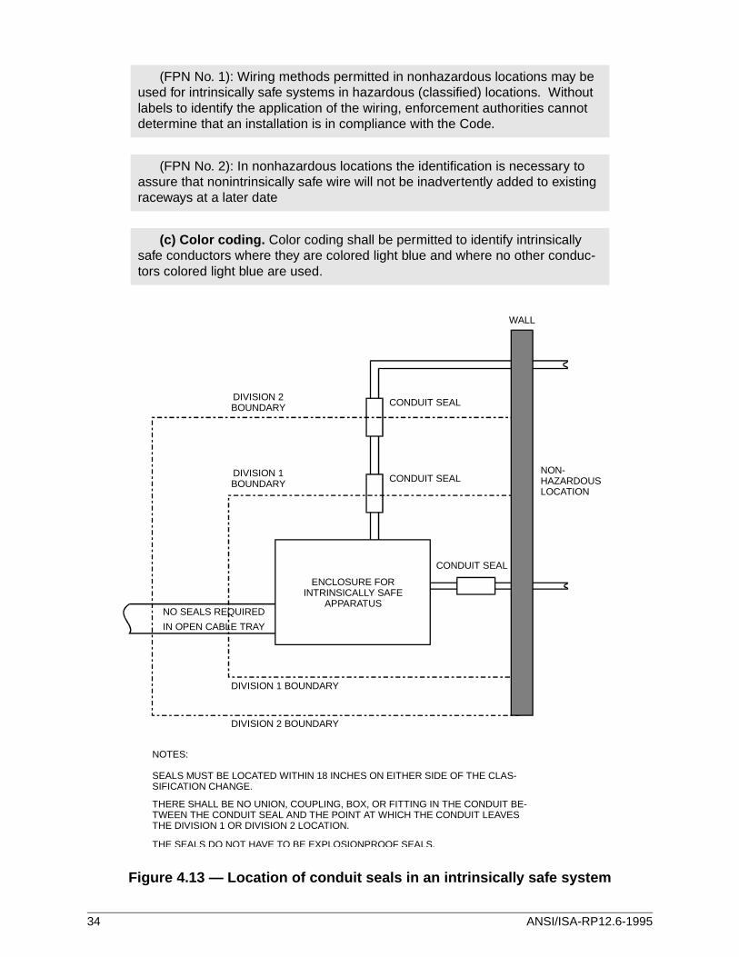
Figure 4.13 — Location of conduit seals in an intrinsically safe system
(FPN No. 1): Wiring methods permitted in nonhazardous locations may be used for intrinsically safe systems in hazardous (classified) locations. Without labels to identify the application of the wiring, enforcement authorities cannot determine that an installation is in compliance with the Code.
(FPN No. 2): In nonhazardous locations the identification is necessary to assure that nonintrinsically safe wire will not be inadvertently added to existing raceways at a later date
(c) Color coding. Color coding shall be permitted to identify intrinsically safe conductors where they are colored light blue and where no other conduc-tors colored light blue are used.
DIVISION 2BOUNDARY
DIVISION 2 BOUNDARY
NOTES:
SEALS MUST BE LOCATED WITHIN 18 INCHES ON EITHER SIDE OF THE CLAS-SIFICATION CHANGE.
THERE SHALL BE NO UNION, COUPLING, BOX, OR FITTING IN THE CONDUIT BE-TWEEN THE CONDUIT SEAL AND THE POINT AT WHICH THE CONDUIT LEAVESTHE DIVISION 1 OR DIVISION 2 LOCATION.
THE SEALS DO NOT HAVE TO BE EXPLOSIONPROOF SEALS.
DIVISION 1BOUNDARY
DIVISION 1 BOUNDARY
NO SEALS REQUIRED
IN OPEN CABLE TRAY
NON-HAZARDOUSLOCATION
CONDUIT SEAL
CONDUIT SEAL
CONDUIT SEAL
WALL
ENCLOSURE FORINTRINSICALLY SAFE
APPARATUS
34 ANSI/ISA-RP12.6-1995
5 Guidelines for combinations of apparatus under the entity concept
5.1 General
5.1.1 The entity concept allows the user to identify acceptable combinations of intrinsically safe apparatus and associated apparatus that have not been examined as a system. Each apparatus is examined separately by a nationally recognized test laboratory (NRTL) and assigned a set of parameters called entity parameters.
5.1.2* Intrinsically safe apparatus is assigned Vmax, Imax, Ci, and Li.
5.1.3 Each channel of associated apparatus is assigned Voc, Isc, Ca, and La.
5.1.4 Combinations of channels of associated apparatus are assigned Vt, It, Ca, and La.
5.1.5 Each intrinsically safe apparatus should have a control drawing that specifies Vmax, Imax, Ci, and Li, and the terminals to which they apply. An intrinsically safe apparatus that has more than one intrinsically safe circuit may have a different set of parameters for each circuit. When this is the case, each circuit may be considered as a separate entity for connection to associated appa-ratus. However, the requirements of NEC® Section 504-30(b) apply for separation of the circuits in the installation.
5.1.6 Each associated apparatus has a control drawing that specifies output parameters for the set of terminals to be connected to the intrinsically safe apparatus. Single-channel associated apparatus will have one set of Voc, Isc, Ca, and La parameters. Multi-channel associated apparatus will have one set of Voc, Isc, Ca, and La parameters for each channel and a separate set of Vt, It, Ca, and La parameters for combinations of channels. Systems that have more than one associated apparatus may also need a control drawing that specifies Vt, It, Ci, and Li parameters of the combination of channels to be connected to the intrinsically safe apparatus. The parameters that apply to the exact interconnection must be used to assess the intrinsic safety of the system.
5.1.7 The length of cable connecting intrinsically safe equipment with associated equipment may be limited because of the energy-storing characteristics of the cable. The control drawing provides guidance in determining the maximum allowed capacitance and inductance. If the electrical pa-rameters of the cable used are unknown, the following values may be used:
Capacitance - 60 pF/ft
Inductance - 0.20 µH/ft
5.1.8* Simple apparatus must comply with the control drawing provided with the associated apparatus.
Exception: Simple apparatus that does not interconnect intrinsically safe circuits.
5.1.9 Simple apparatus need not be listed or labeled.
*Further information may be found in Annex A.
ANSI/ISA-RP12.6-1995 35
5.2 Assessing the intrinsic safety of combinations of intrinsically safe and associated apparatus
5.2.1 For systems that have a single-channel associated apparatus connected to only one intrin-sically safe apparatus, the interconnection is intrinsically safe if:
Vmax ≥ Voc
Imax ≥ Isc
(Ci + Ccable) ≤ Ca
(Li + Lcable) ≤ La
NOTE: The capacitance and inductance of the interconnecting cable must be added to that of the intrinsically safe apparatus.
5.2.2 For systems that have more than one channel of associated apparatus connected to a single intrinsically safe apparatus, the interconnection is intrinsically safe if:
Vmax ≥ Vt
Imax ≥ It
Ca ≤ (Ci + Ccable)
La ≤ (Li + Lcable)
5.2.3 For systems that have a single-channel associated apparatus connected to more than one intrinsically safe apparatus, the interconnection is intrinsically safe if:
Vmax ≥ Voc for each intrinsically safe apparatus
Imax ≥ Isc for each intrinsically safe apparatus
Ca ≥ (Citot + Ccable) where Citot = sum of individual Ci values
La ≥ (Litot + Lcable) where Litot = sum of individual Li values
5.2.4 For systems that have more than one channel of associated apparatus connected to more than one intrinsically safe apparatus, the interconnection is intrinsically safe if:
Vmax ≥ Vt for each intrinsically safe apparatus
Imax ≥ It for each intrinsically safe apparatus
Ca ≥ (Citot + Ccable) where Citot = sum of individual Ci values
La ≥ (Litot + Lcable) where Litot = sum of individual Li values
5.2.5 For systems that have more than one channel of associated apparatus connected to a single intrinsically safe apparatus where separate parameters have been specified for each channel, the interconnection is intrinsically safe if, for each channel:
Vmax ≥ Voc
Imax ≥ Isc
Ca ≥ (Ci + Ccable)
La ≥ (Li + Lcable)
Both associated apparatus channels must be of the same polarity.
36 ANSI/ISA-RP12.6-1995
The Ca and La ratings used to calculate the maximum allowed cable capacitance and inductance will be the lower value of either associated apparatus of either channel.
5.3 Intrinsically safe apparatus with more than one intrinsically safe circuit
5.3.1 Intrinsically safe apparatus with more than one intrinsically safe circuit may require special isolation between the circuits. The control drawing will specify if more than one circuit is involved and whether the circuits have to be isolated.
5.3.2 When each circuit must be isolated, the requirements of NEC® Clause 504-30(b) apply.
5.3.3* Maintenance should be restricted to one circuit at a time unless intrinsic safety is not im-paired.
6 Maintenance and inspection
6.1 General
6.1.1 Maintenance and inspection procedures should be performed by qualified persons and should not compromise intrinsic safety.
CAUTION — ALTHOUGH INTRINSICALLY SAFE CIRCUITS ARE INHERENTLY LOW ENERGY, THEY MAY STILL PRESENT A SHOCK HAZARD BECAUSE OF THE OPERATING VOLTAGE.
6.1.2 Inspection should be performed periodically to ensure that intrinsic safety has not been compromised. Inspections should include reviewing for unauthorized modifications, corrosion, accidental damage, change of flammable materials, and the effects of aging.
6.2 Ensuring that maintenance and inspection does not compromise intrinsic safety
6.2.1 User replaceable parts of an intrinsically safe system should not be replaced with other than the manufacturer's direct equivalent.
6.2.2**Maintenance work may be performed on energized apparatus subject to the conditions detailed below:
a) Maintenance work in hazardous areas should be restricted to the following:
1) Disconnection of, and removal or replacement of, items of electrical apparatus and cabling if such action will not result in shorting of different intrinsically safe circuits.
*Further information may be found in Annex A.**Further information may be found in Annex A.
ANSI/ISA-RP12.6-1995 37
2) Adjustment of any control that is necessary for the calibration of the electrical apparatus or system.
3) Only test instruments specified in the relevant documentation should be used.
4) Performance of other maintenance activities specifically permitted by the relevant control drawing and instruction manual.
Persons performing maintenance described above should ensure that the intrinsicallysafe system or self-contained intrinsically safe apparatus meets the requirements ofthe relevant documentation after completion of any of the work.
b) Maintenance of associated apparatus and parts of intrinsically safe circuits located in nonhazardous areas should be restricted to that described in a way such that electrical apparatus or parts of circuits remain interconnected with parts of intrinsically safe systems located in hazardous areas. Safety barrier ground connections should not be removed without first disconnecting the hazardous area circuits.
Other maintenance work on associated apparatus or parts of an intrinsically safe circuitmounted in a nonhazardous area should be performed only if the electrical apparatusor part of a circuit is disconnected from the part of the circuit located in a hazardousarea.
6.2.3 The following are examples of operations not allowable without first de-energizing the intrin-sically safe circuits at the associated apparatus or confirming that a flammable atmosphere is not present.
a) Disconnecting or pulling cables with multiple intrinsically safe circuits unless such action will not result in shorting of different intrinsically safe circuits — e.g., by insulating each wire termination immediately after disconnecting it from the intrinsically safe apparatus
b) Disconnecting multiple intrinsically safe circuits in the same intrinsically safe apparatus or terminal junction box unless such action will not result in shorting different intrinsically safe circuits
c) Using test equipment that is not permitted by the relevant documentation
d) Jumpering circuits or components in the intrinsically safe apparatus
6.3 Inspecting an intrinsically safe system
6.3.1 The location classification and the suitability of the intrinsically safe system for that classifi-cation should be verified. This includes verifying that the class, group, and temperature ratings of both the intrinsically safe apparatus and the associated apparatus agree with the actual classifi-cation of the location.
6.3.2 Intrinsically safe systems should be inspected to ensure that the:
a) Installation is in compliance with the documentation
b) Intrinsically safe circuits are properly separated from nonintrinsically safe circuits
c) Cable shields are grounded in accordance with the installation documentation
d) Modifications have been authorized
e) cables and wiring are not damaged
38 ANSI/ISA-RP12.6-1995
f) Bonding and grounding connections are tight
g) Bonding and grounding hardware is not corroded
h) Resistance of any grounding conductor, including termination resistance from shunt type associated apparatus to the grounding electrode does not exceed one ohm
i) Protection has not been defeated by bypassing
j) Printed circuit boards are clean and undamaged
6.3.3 All deficiencies should be corrected.
ANSI/ISA-RP12.6-1995 39

Annex A — Explanatory notes
This annex is not part of ANSI/ISA-RP12.6, but is included to facilitate its use. The notes below are numbered to correspond to the related section (noted with an asterisk) in the text; therefore, the numbers do not follow a numerical sequence.
A.1.1 For formal interpretations of the requirements of NEC® Article 504 and other articles of the National Electrical Code®, see Article 90-5 of NFPA 70.
A.5.1.2 The values of Vmax and Imax are selected by the manufacturer of the intrinsically safe apparatus to allow connection of the intrinsically safe apparatus with as wide a variety of associated apparatus as possible. Vmax and Imax represent worst case associated apparatus fault conditions and do not necessarily bear any relationship to the normal operating voltage and current parameters of the intrinsically safe apparatus. Vmax and Imax are limited only by the maximum voltage and current that the intrinsically safe apparatus can receive and remain intrinsically safe, based on stored energy and thermal considerations. The Vmax and Imax values specified for a given intrin-sically safe apparatus, taken together and compared to the ignition curves (ref. ANSI/UL 913), probably will fall in the ignition-capable area of the curve. This does not represent a problem, however, since any NRTL-approved associated apparatus must have a Voc and Isc combination that is not ignition-capable. For example, an intrinsically safe apparatus with low Ci and Li values and properly rated components could realistically have a Vmax of 45 volts and an Imax of 350 mA. 350 mA is well into the ignition-capable area of the ignition curve at 45 volts. However, based on the ignition curve for Groups A and B, an associated apparatus with a Voc of 45 volts would have an Isc of no more than 45 mA, and an associated apparatus with an Isc of 350 mA would be limited to a Voc of no more than 19 volts. The connection of either associated apparatus to the intrinsically safe apparatus would result in an intrinsically safe system, since in both cases, Vmax ≥ Voc and Imax ≥ Isc. Care must be taken by the user, however, to evaluate the effects of cable capacitance and inductance on the suitability of the system, and ensure that the proper operational voltage and current levels for the intrinsically safe apparatus are available from the associated apparatus se-lected.
A.5.1.8 A simple apparatus may be assumed to interconnect any circuits to which it is connected. Therefore, if a simple apparatus is connected to more than one channel of associated apparatus, there must be a control drawing documenting that the combination of channels may be connected to simple apparatus.
Wiring devices such as connectors and terminal blocks may be used in intrinsically safe systems, as necessary. They are not considered as either intrinsically safe apparatus or as simple apparatus, and do not need to be shown on control drawings. The wiring devices must not compromise spacings between different intrinsically safe circuits or between intrinsically safe and non-intrinsically safe circuits.
ANSI/ISA-RP12.6-1995 41
A.5.3.3 An intrinsically safe circuit has been evaluated for the consequences of shorting, opening, or grounding the wires. However, if more than one intrinsically safe circuit is present, maintenance that intentionally or accidentally interconnects the circuits may compromise intrinsic safety.
A.6.2.2 It is preferred that maintenance and inspection be performed only when the flammable atmosphere is not present. In some cases, the flammable material may also be toxic. Ignition of the flammable atmosphere may also occur because of dropped tools, static charge, etc.
Figure A.1 — Various configurations of intrinsically safe systems
42 ANSI/ISA-RP12.6-1995
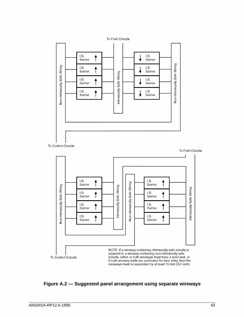
Figure A.2 — Suggested panel arrangement using separate wireways
ANSI/ISA-RP12.6-1995 43

Annex B — Wiring in hazardous (classified) locations
This annex is not part of ISA-RP12.6, but is included to facilitate its use.
B.1 Wiring in hazardous locations
Table B.1 includes the concept of a Division 0 location, to correspond with Zone 0, as defined in the International Electrotechnical Commission Publication 79-10 (1972), "Electrical Apparatus for Explosive Gas Atmospheres, Part 10: Classification of Hazardous Areas," as an area in which an explosive atmosphere is continuously present or present for long periods. This condition is included in the definition of Division 1 in the NEC® (1993) and the CEC (1990). The concept is presented here for additional information. Table B.2 is included for the same reason.
ANSI/ISA-RP12.6-1995 45
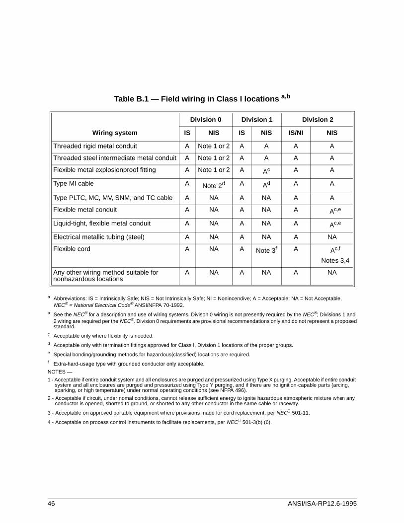
Table B.1 — Field wiring in Class I locations a,b
a Abbreviations: IS = Intrinsically Safe; NIS = Not Intrinsically Safe; NI = Nonincendive; A = Acceptable; NA = Not Acceptable,NEC® = National Electrical Code® ANSI/NFPA 70-1992.
b See the NEC® for a description and use of wiring systems. Divison 0 wiring is not presently required by the NEC®; Divisions 1 and 2 wiring are required per the NEC®. Division 0 requirements are provisional recommendations only and do not represent a proposedstandard.
c Acceptable only where flexibility is needed.d Acceptable only with termination fittings approved for Class I, Division 1 locations of the proper groups.e Special bonding/grounding methods for hazardous(classified) locations are required.f Extra-hard-usage type with grounded conductor only acceptable.
NOTES —
1 - Acceptable if entire conduit system and all enclosures are purged and pressurized using Type X purging. Acceptable if entire conduit system and all enclosures are purged and pressurized using Type Y purging, and if there are no ignition-capable parts (arcing, sparking, or high temperature) under normal operating conditions (see NFPA 496).
2 - Acceptable if circuit, under nomal conditions, cannot release sufficient energy to ignite hazardous atmospheric mixture when any conductor is opened, shorted to ground, or shorted to any other conductor in the same cable or raceway.
3 - Acceptable on approved portable equipment where provisions made for cord replacement, per NEC 501-11.
4 - Acceptable on process control instruments to facilitate replacements, per NEC 501-3(b) (6).
Division 0 Division 1 Division 2
Wiring system IS NIS IS NIS IS/NI NIS
Threaded rigid metal conduit A Note 1 or 2 A A A A
Threaded steel intermediate metal conduit A Note 1 or 2 A A A A
Flexible metal explosionproof fitting A Note 1 or 2 A Ac A A
Type MI cable A Note 2d A Ad A A
Type PLTC, MC, MV, SNM, and TC cable A NA A NA A A
Flexible metal conduit A NA A NA A Ac,e
Liquid-tight, flexible metal conduit A NA A NA A Ac,e
Electrical metallic tubing (steel) A NA A NA A NA
Flexible cord A NA A Note 3f A Ac,f
Notes 3,4
Any other wiring method suitable for nonhazardous locations
A NA A NA A NA
46 ANSI/ISA-RP12.6-1995
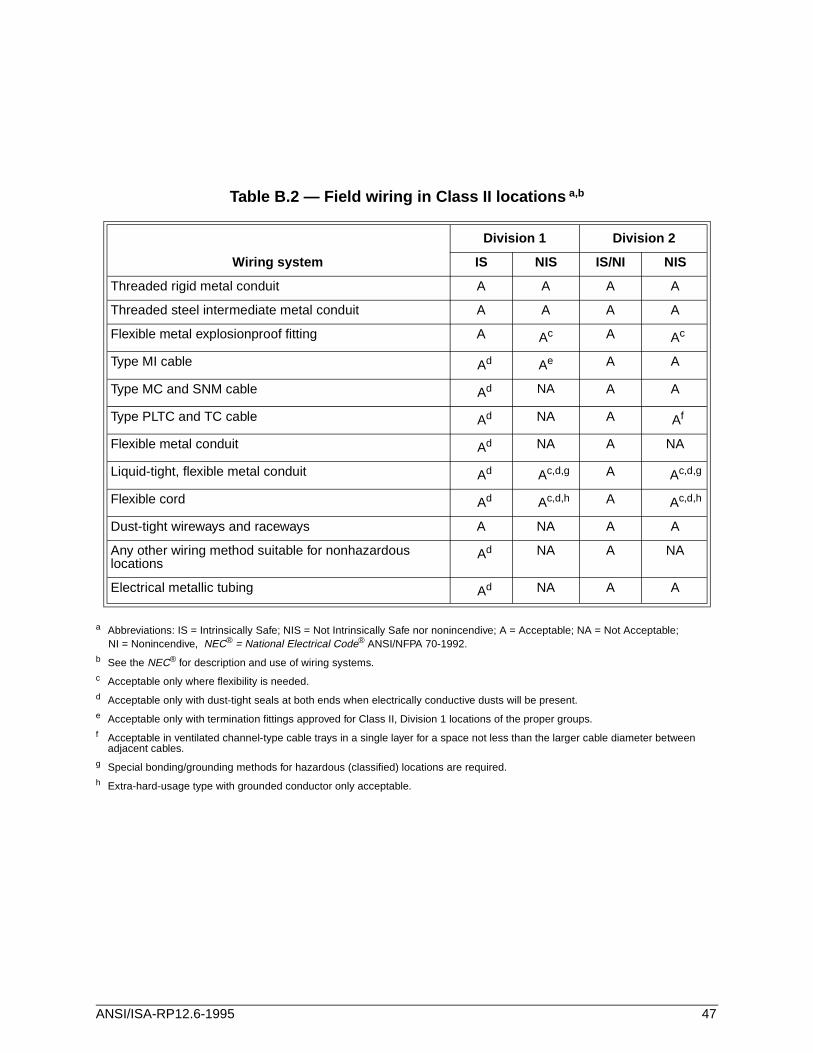
Table B.2 — Field wiring in Class II locations a,b
a Abbreviations: IS = Intrinsically Safe; NIS = Not Intrinsically Safe nor nonincendive; A = Acceptable; NA = Not Acceptable;NI = Nonincendive, NEC® = National Electrical Code® ANSI/NFPA 70-1992.
b See the NEC® for description and use of wiring systems.c Acceptable only where flexibility is needed.d Acceptable only with dust-tight seals at both ends when electrically conductive dusts will be present.e Acceptable only with termination fittings approved for Class II, Division 1 locations of the proper groups.f Acceptable in ventilated channel-type cable trays in a single layer for a space not less than the larger cable diameter between
adjacent cables.g Special bonding/grounding methods for hazardous (classified) locations are required.h Extra-hard-usage type with grounded conductor only acceptable.
Division 1 Division 2
Wiring system IS NIS IS/NI NIS
Threaded rigid metal conduit A A A A
Threaded steel intermediate metal conduit A A A A
Flexible metal explosionproof fitting A Ac A Ac
Type MI cable Ad Ae A A
Type MC and SNM cable Ad NA A A
Type PLTC and TC cable Ad NA A Af
Flexible metal conduit Ad NA A NA
Liquid-tight, flexible metal conduit Ad Ac,d,g A Ac,d,g
Flexible cord Ad Ac,d,h A Ac,d,h
Dust-tight wireways and raceways A NA A A
Any other wiring method suitable for nonhazardous locations
Ad NA A NA
Electrical metallic tubing Ad NA A A
ANSI/ISA-RP12.6-1995 47

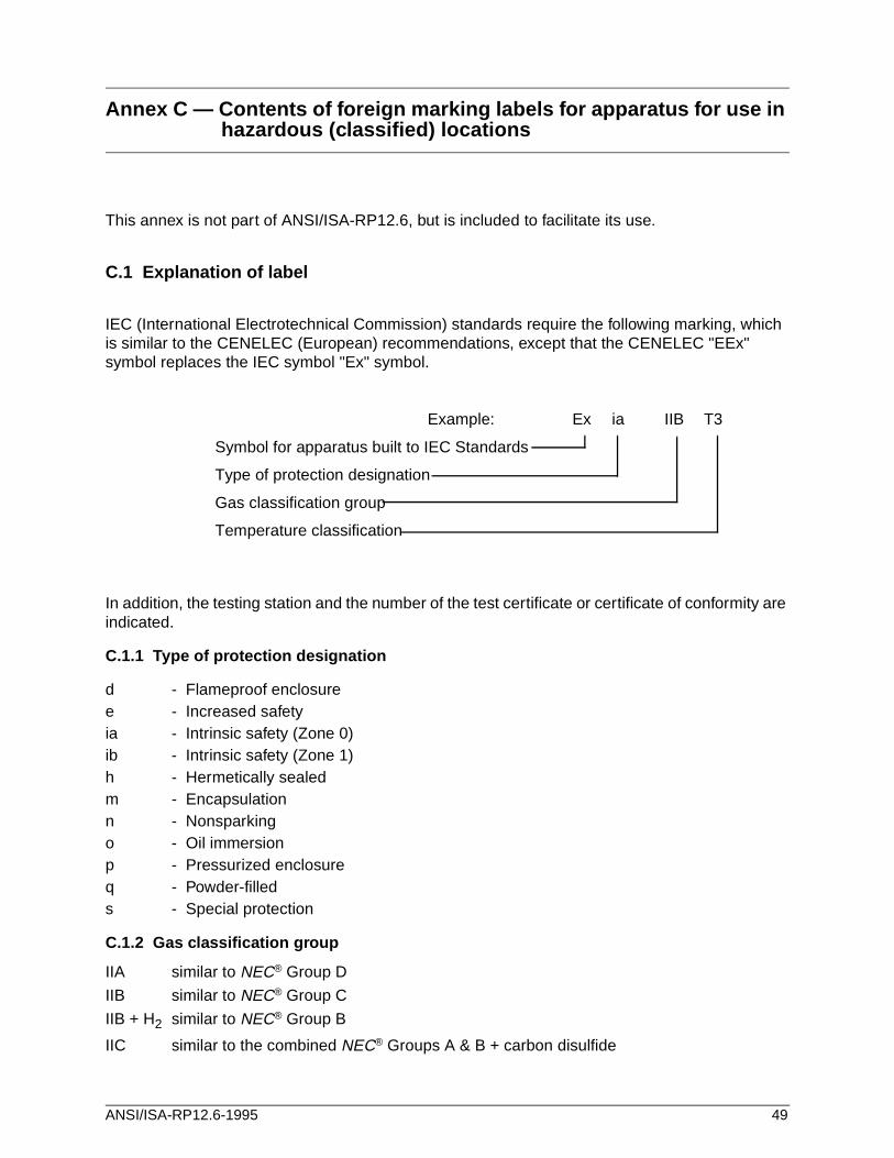
Annex C — Contents of foreign marking labels for apparatus for use in hazardous (classified) locations
This annex is not part of ANSI/ISA-RP12.6, but is included to facilitate its use.
C.1 Explanation of label
IEC (International Electrotechnical Commission) standards require the following marking, which is similar to the CENELEC (European) recommendations, except that the CENELEC "EEx" symbol replaces the IEC symbol "Ex" symbol.
In addition, the testing station and the number of the test certificate or certificate of conformity are indicated.
C.1.1 Type of protection designation
d - Flameproof enclosuree - Increased safetyia - Intrinsic safety (Zone 0)ib - Intrinsic safety (Zone 1)h - Hermetically sealedm - Encapsulationn - Nonsparkingo - Oil immersionp - Pressurized enclosureq - Powder-filleds - Special protection
C.1.2 Gas classification group
IIA similar to NEC® Group D
IIB similar to NEC® Group C
IIB + H2 similar to NEC® Group B
IIC similar to the combined NEC® Groups A & B + carbon disulfide
Example: Ex ia IIB T3
Symbol for apparatus built to IEC Standards
Type of protection designation
Gas classification group
Temperature classification
ANSI/ISA-RP12.6-1995 49
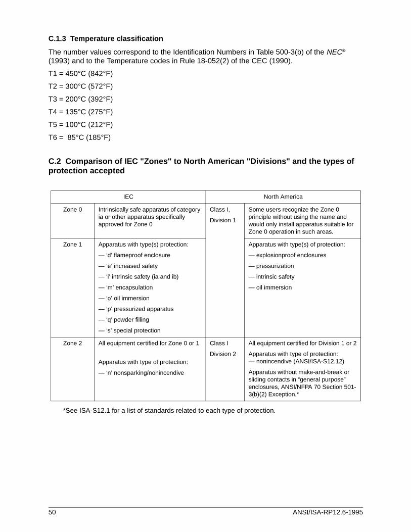
C.1.3 Temperature classification
The number values correspond to the Identification Numbers in Table 500-3(b) of the NEC® (1993) and to the Temperature codes in Rule 18-052(2) of the CEC (1990).
T1 = 450°C (842°F)
T2 = 300°C (572°F)
T3 = 200°C (392°F)
T4 = 135°C (275°F)
T5 = 100°C (212°F)
T6 = 85°C (185°F)
C.2 Comparison of IEC "Zones" to North American "Divisions" and the types of protection accepted
IEC North America
Zone 0 Intrinsically safe apparatus of category ia or other apparatus specifically approved for Zone 0
Class I,
Division 1
Some users recognize the Zone 0 principle without using the name and would only install apparatus suitable for Zone 0 operation in such areas.
Zone 1 Apparatus with type(s) protection:
— ‘d’ flameproof enclosure
— ‘e’ increased safety
— ‘i’ intrinsic safety (ia and ib)
— ‘m’ encapsulation
— ‘o’ oil immersion
— ‘p’ pressurized apparatus
— ‘q’ powder filling
— ‘s’ special protection
Apparatus with type(s) of protection:
— explosionproof enclosures
— pressurization
— intrinsic safety
— oil immersion
Zone 2 All equipment certified for Zone 0 or 1
Apparatus with type of protection:
— ‘n’ nonsparking/nonincendive
Class I
Division 2
All equipment certified for Division 1 or 2
Apparatus with type of protection:— nonincendive (ANSI/ISA-S12.12)
Apparatus without make-and-break or sliding contacts in “general purpose” enclosures, ANSI/NFPA 70 Section 501-3(b)(2) Exception.*
*See ISA-S12.1 for a list of standards related to each type of protection.
50 ANSI/ISA-RP12.6-1995
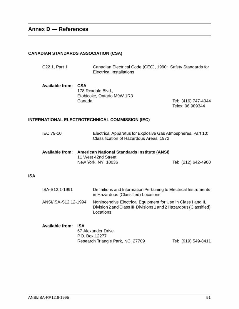
Annex D — References
CANADIAN STANDARDS ASSOCIATION (CSA)
C22.1, Part 1 Canadian Electrical Code (CEC), 1990: Safety Standards for Electrical Installations
Available from: CSA178 Rexdale Blvd., Etobicoke, Ontario M9W 1R3Canada Tel: (416) 747-4044
Telex: 06 989344
INTERNATIONAL ELECTROTECHNICAL COMMISSION (IEC)
IEC 79-10 Electrical Apparatus for Explosive Gas Atmospheres, Part 10: Classification of Hazardous Areas, 1972
Available from: American National Standards Institute (ANSI)11 West 42nd StreetNew York, NY 10036 Tel: (212) 642-4900
ISA
ISA-S12.1-1991 Definitions and Information Pertaining to Electrical Instruments in Hazardous (Classified) Locations
ANSI/ISA-S12.12-1994 Nonincendive Electrical Equipment for Use in Class I and II, Division 2 and Class III, Divisions 1 and 2 Hazardous (Classified) Locations
Available from: ISA67 Alexander DriveP.O. Box 12277Research Triangle Park, NC 27709 Tel: (919) 549-8411
ANSI/ISA-RP12.6-1995 51
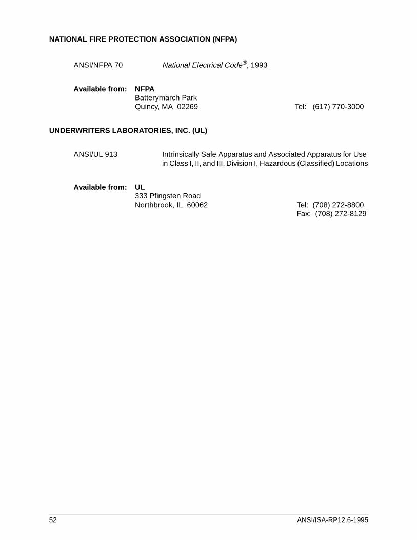
NATIONAL FIRE PROTECTION ASSOCIATION (NFPA)
ANSI/NFPA 70 National Electrical Code®, 1993
Available from: NFPABatterymarch ParkQuincy, MA 02269 Tel: (617) 770-3000
UNDERWRITERS LABORATORIES, INC. (UL)
ANSI/UL 913 Intrinsically Safe Apparatus and Associated Apparatus for Use in Class I, II, and III, Division I, Hazardous (Classified) Locations
Available from: UL333 Pfingsten RoadNorthbrook, IL 60062 Tel: (708) 272-8800
Fax: (708) 272-8129
52 ANSI/ISA-RP12.6-1995

Developing and promulgating technically sound consensus standards, recommended practices, and technical reports is one of ISA's primary goals. To achieve this goal the Standards and Practices Department relies on the technical expertise and efforts of volunteer committee members, chairmen, and reviewers.
ISA is an American National Standards Institute (ANSI) accredited organization. ISA administers United States Technical Advisory Groups (USTAGs) and provides secretariat support for International Electrotechnical Commission (IEC) and International Organization for Standardization (ISO) committees that develop process measurement and control standards. To obtain additional information on the Society's standards program, please write:
ISAAttn: Standards Department67 Alexander DriveP.O. Box 12277Research Triangle Park, NC 27709
ISBN: 1-55617-545-0