Embed Size (px)
Citation preview
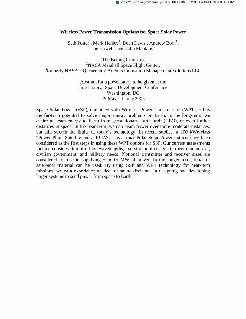
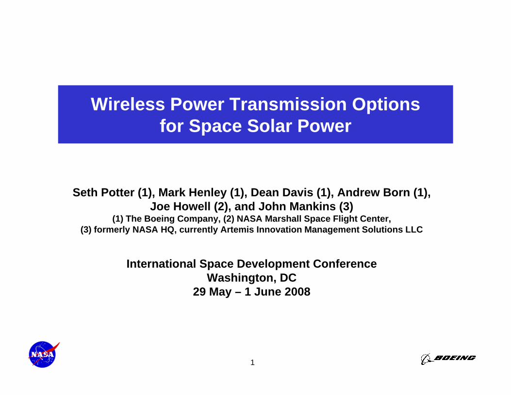
Wireless Power Transmission Options for Space Solar Power
Seth Potter1, Mark Henley1, Dean Davis1, Andrew Born1, Joe Howell2, and John Mankins3
1The Boeing Company,
2NASA Marshall Space Flight Center, 3formerly NASA HQ, currently Artemis Innovation Management Solutions LLC
Abstract for a presentation to be given at the International Space Development Conference
Washington, DC 29 May – 1 June 2008
Space Solar Power (SSP), combined with Wireless Power Transmission (WPT), offers the far-term potential to solve major energy problems on Earth. In the long-term, we aspire to beam energy to Earth from geostationary Earth orbit (GEO), or even further distances in space. In the near-term, we can beam power over more moderate distances, but still stretch the limits of today’s technology. In recent studies, a 100 kWe-class “Power Plug” Satellite and a 10 kWe-class Lunar Polar Solar Power outpost have been considered as the first steps in using these WPT options for SSP. Our current assessments include consideration of orbits, wavelengths, and structural designs to meet commercial, civilian government, and military needs. Notional transmitter and receiver sizes are considered for use in supplying 5 to 15 MW of power. In the longer term, lunar or asteroidal material can be used. By using SSP and WPT technology for near-term missions, we gain experience needed for sound decisions in designing and developing larger systems to send power from space to Earth.
https://ntrs.nasa.gov/search.jsp?R=20080036588 2019-04-04T11:30:38+00:00Z
Wireless Power Transmission Optionsfor Space Solar Powerfor Space Solar Power
Seth Potter (1), Mark Henley (1), Dean Davis (1), Andrew Born (1),Joe Howell (2), and John Mankins (3)
(1) The Boeing Company, (2) NASA Marshall Space Flight Center,( ) g p y, ( ) p g ,(3) formerly NASA HQ, currently Artemis Innovation Management Solutions LLC
International Space Development ConferenceWashington, DC
29 May – 1 June 2008
1
Wireless Power Transmission Optionsfor Space Solar Power:
P i St di t B i d NASAPrevious Studies at Boeing and NASA
• Far Term Space Systems to beam power to EarthFar Term Space Systems to beam power to Earth– Radio-Wave WPT System– Light-Wave Systems
Photovoltaic power generation– Photovoltaic power generation– Solar dynamic power generation– Power levels of 1 to 10 GW, beamed from
t ti bitgeostationary orbit
• Near term Technology Flight Demonstrationsgy g– Model System Concept 1A: 100 kWe satellite– Model System Concept 1B: 10 kWe lunar system
2
Current Boeing StudyTask 1 Mission analysis for space solar power• Task 1. Mission analysis for space solar power
– Military mission needs for supplying power to military bases and military vehicles in dangerous and remote locations, for peace, crisis and war situations, for both peak power load and base load
– Civil government mission needs for supplying power to civil government bases and vehicles in dangerous and remote locations on earth in orbit and deep space for both peak power loaddangerous and remote locations, on earth, in orbit, and deep space, for both peak power load and base load
– Commercial user needs for supplying power to commercial users on the commercial power grid or in dangerous and remote locations, on earth, in orbit, and deep space, for both peak power load and base load
• Task 2 Space solar power technology & architecture analysis• Task 2. Space solar power technology & architecture analysis– Perform a literature search of key technologies – Assess architecture – Assess the environmental impact, political considerations, and identify stakeholders – Perform orbital analysis for constellation optimization of space power satellites at various orbital
configurations • Task 3. Logistics analysis
– Analysis of transportation methods (e.g. rail gun, chemical rockets) for getting satellites into orbit (from moon or earth),
– Conduct a mass-flow analysis for converting X kg of extra-terrestrial matter (regolith moon dustConduct a mass flow analysis, for converting X kg of extra terrestrial matter (regolith, moon dust, asteroid material, or equivalent) to Y kg of satellite components via in-situ resource utilization (ISRU), then construction into space solar power satellites
• Task 4. Cost analysis for space solar power– Assess costs for manufacturing, transporting, operating, and servicing solar power satellites
Compare cost of energy conversion and distribution (kw hour) for various existing and expected
3
– Compare cost of energy conversion and distribution (kw-hour) for various existing and expected military, civil government, and commercial methods (solar power satellites, terrestrial solar, nuclear, fossil fuel)
Boeing Trade Studies in Progress
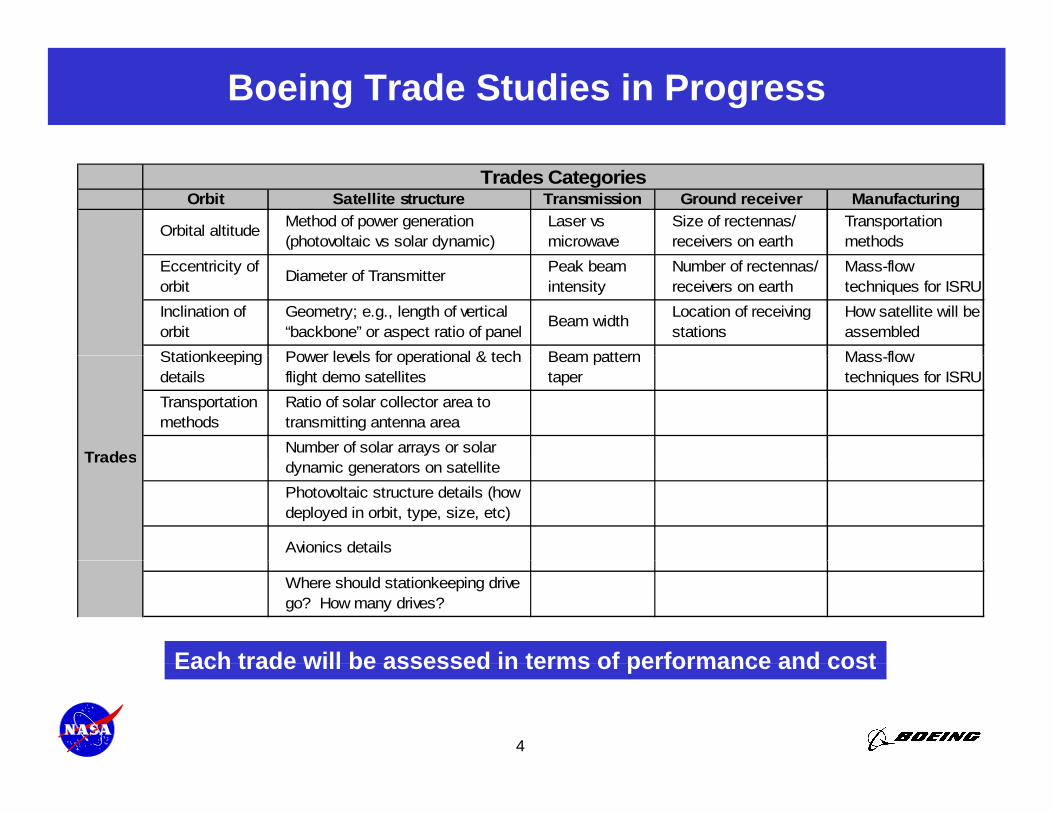
Orbit Satellite structure Transmission Ground receiver Manufacturing
Orbital altitude Method of power generation (photovoltaic vs solar dynamic)
Laser vs microwave
Size of rectennas/ receivers on earth
Transportation methods
Trades Categories
Eccentricity of orbit
Diameter of Transmitter Peak beam intensity
Number of rectennas/ receivers on earth
Mass-flow techniques for ISRU
Inclination of orbit
Geometry; e.g., length of vertical “backbone” or aspect ratio of panel
Beam width Location of receiving stations
How satellite will be assembled
Stationkeeping Power levels for operational & tech Beam pattern Mass flowStationkeeping details
Power levels for operational & tech flight demo satellites
Beam pattern taper
Mass-flow techniques for ISRU
Transportation methods
Ratio of solar collector area to transmitting antenna areaNumber of solar arrays or solar Trades dynamic generators on satellitePhotovoltaic structure details (how deployed in orbit, type, size, etc)
Avionics details
Trades
Where should stationkeeping drive go? How many drives?
Each trade will be assessed in terms of performance and cost
4
Each trade will be assessed in terms of performance and cost
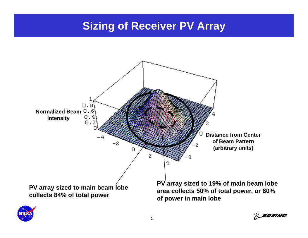
Sizing of Receiver PV Array
Normalized Beam Intensity
Distance from CenterDistance from Centerof Beam Pattern (arbitrary units)
PV array sized to main beam lobe collects 84% of total power
PV array sized to 19% of main beam lobe area collects 50% of total power, or 60%
5
collects 84% of total power pof power in main lobe
Near-Term Market: Military Bases
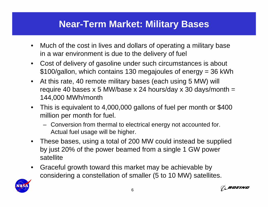
• Much of the cost in lives and dollars of operating a military base in a war environment is due to the delivery of fuel
• Cost of delivery of gasoline under such circumstances is aboutCost of delivery of gasoline under such circumstances is about $100/gallon, which contains 130 megajoules of energy = 36 kWh
• At this rate, 40 remote military bases (each using 5 MW) will require 40 bases x 5 MW/base x 24 hours/day x 30 days/month =require 40 bases x 5 MW/base x 24 hours/day x 30 days/month 144,000 MWh/month
• This is equivalent to 4,000,000 gallons of fuel per month or $400 million per month for fuelmillion per month for fuel.– Conversion from thermal to electrical energy not accounted for.
Actual fuel usage will be higher.• These bases using a total of 200 MW could instead be suppliedThese bases, using a total of 200 MW could instead be supplied
by just 20% of the power beamed from a single 1 GW power satellite
• Graceful growth toward this market may be achievable by
6
Graceful growth toward this market may be achievable by considering a constellation of smaller (5 to 10 MW) satellites.
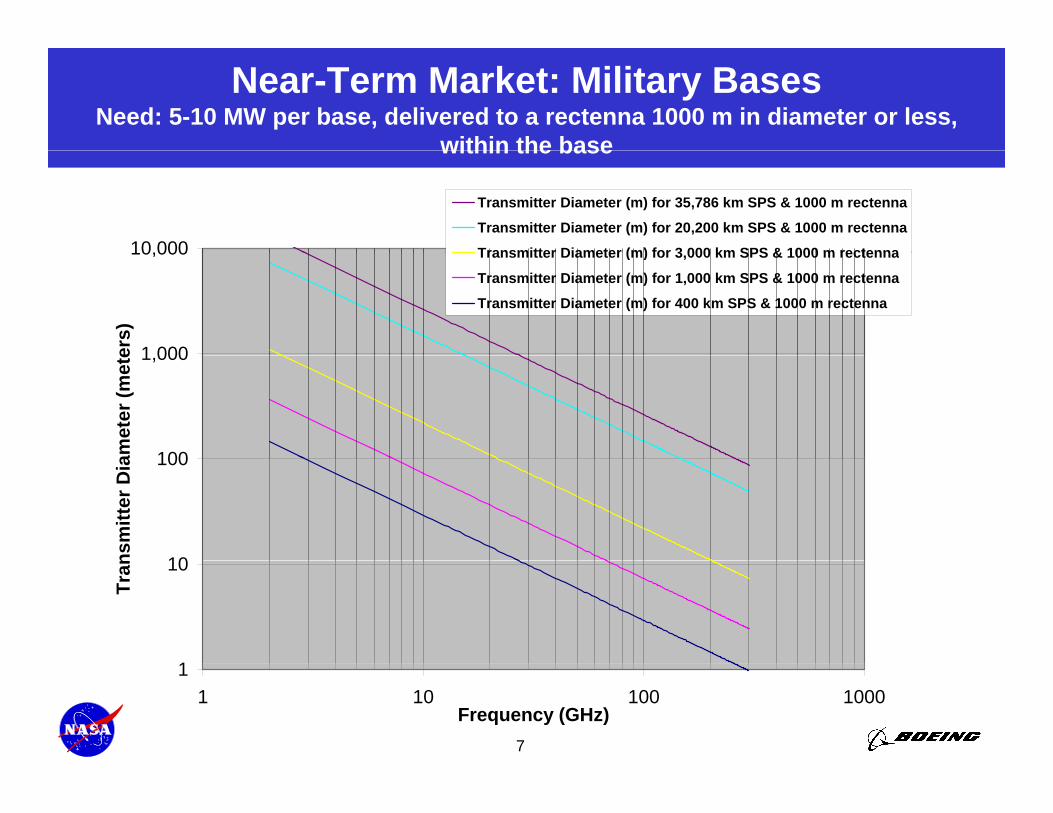
Near-Term Market: Military BasesNeed: 5-10 MW per base, delivered to a rectenna 1000 m in diameter or less,
within the basewithin the base
10,000
Transmitter Diameter (m) for 35,786 km SPS & 1000 m rectenna
Transmitter Diameter (m) for 20,200 km SPS & 1000 m rectenna
Transmitter Diameter (m) for 3 000 km SPS & 1000 m rectenna
1 000
10,000
ers)
Transmitter Diameter (m) for 3,000 km SPS & 1000 m rectenna
Transmitter Diameter (m) for 1,000 km SPS & 1000 m rectenna
Transmitter Diameter (m) for 400 km SPS & 1000 m rectenna
100
1,000
amet
er (m
ete
10
100
nsm
itter
Dia
1
10
Tran
7
11 10 100 1000
Frequency (GHz)
Orbit Trade Study: Altitude (1 of 2)
• Low Earth Orbit (LEO)– Pros:
• Low delta-V so lower launch costs• Low delta-V, so lower launch costs• Less beam divergence, therefore smaller overall system size, leading to
lower cost to first power and ease of integration into near-term niche markets• Graceful growth and degradation
– Cons:Cons:• Satellite is in view of a given rectenna for only a few minutes per orbit, so
many satellites and rectennas would be necessary to maximize power transmission duty cycle and minimize storage
• Beam must be continuously steered, leading to steering losses and sweeping t l l iout large exclusion zones
• Prone to greater drag and space debris• In darkness much of the time, further lowering duty cycle and increasing cost
per installed watt
8
Orbit Trade Study: Altitude (2 of 2)
• High Earth Orbit, particularly GEO– Pros:
• Satellite has long dwell time over rectenna (continuous in GEO), so little or no beam steering is necessaryMi i l b t i l• Minimal beam steering losses
• In almost continuous sunlight• Exclusion zone around beam is large, but fixed
– Cons:• High delta-V, so high launch costsHigh delta V, so high launch costs• High beam divergence, therefore:
– Large antenna size– Large overall system size, leading to higher cost to first power, complex assembly, and
challenging integration into existing markets• Must transmit beam through lower orbitsg
• Middle Earth Orbit (MEO)– Most pro and con characteristics are intermediate between LEO and GEO,
however …– Taking full advantage of MEO altitude may involve placing it in higher inclination
bi Thi ld h h d f l i h lli h iorbits. This would have the advantage of placing the satellite over areas where it is needed much of the time, and may keep it in continuous sunlight much of the year. However, the delta-V to launch to a highly inclined MEO orbit may actually be greater than that for GEO.
9
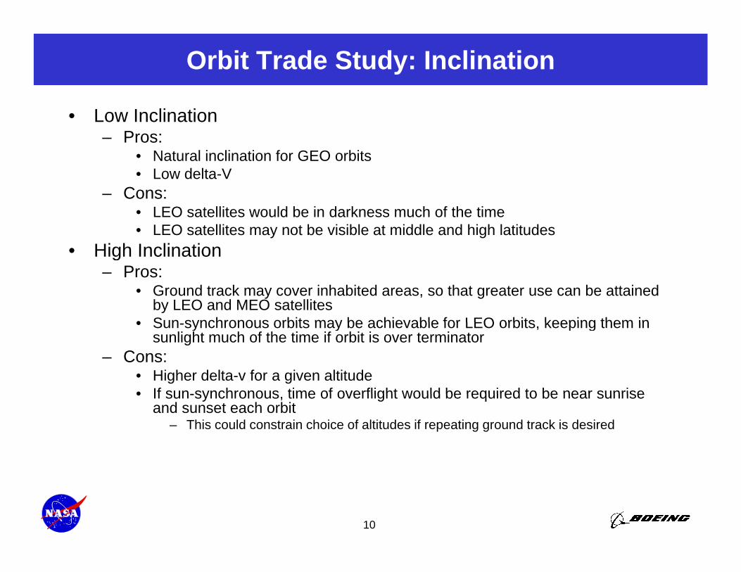
Orbit Trade Study: Inclination
• Low Inclination– Pros:
• Natural inclination for GEO orbits• Low delta-VLow delta V
– Cons:• LEO satellites would be in darkness much of the time• LEO satellites may not be visible at middle and high latitudes
• High Inclination• High Inclination– Pros:
• Ground track may cover inhabited areas, so that greater use can be attained by LEO and MEO satellites
• Sun synchronous orbits may be achievable for LEO orbits keeping them in• Sun-synchronous orbits may be achievable for LEO orbits, keeping them in sunlight much of the time if orbit is over terminator
– Cons:• Higher delta-v for a given altitude• If sun-synchronous time of overflight would be required to be near sunrise• If sun-synchronous, time of overflight would be required to be near sunrise
and sunset each orbit– This could constrain choice of altitudes if repeating ground track is desired
10
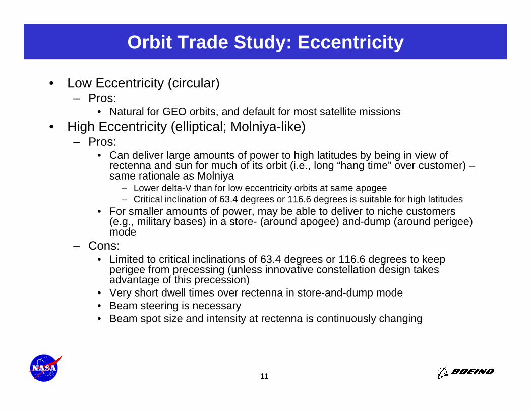
Orbit Trade Study: Eccentricity
• Low Eccentricity (circular)– Pros:
• Natural for GEO orbits, and default for most satellite missions• High Eccentricity (elliptical; Molniya-like)• High Eccentricity (elliptical; Molniya-like)
– Pros:• Can deliver large amounts of power to high latitudes by being in view of
rectenna and sun for much of its orbit (i.e., long “hang time” over customer) –same rationale as Molniyasame rationale as Molniya
– Lower delta-V than for low eccentricity orbits at same apogee– Critical inclination of 63.4 degrees or 116.6 degrees is suitable for high latitudes
• For smaller amounts of power, may be able to deliver to niche customers (e.g., military bases) in a store- (around apogee) and-dump (around perigee) modemode
– Cons:• Limited to critical inclinations of 63.4 degrees or 116.6 degrees to keep
perigee from precessing (unless innovative constellation design takes advantage of this precession)advantage of this precession)
• Very short dwell times over rectenna in store-and-dump mode• Beam steering is necessary• Beam spot size and intensity at rectenna is continuously changing
11
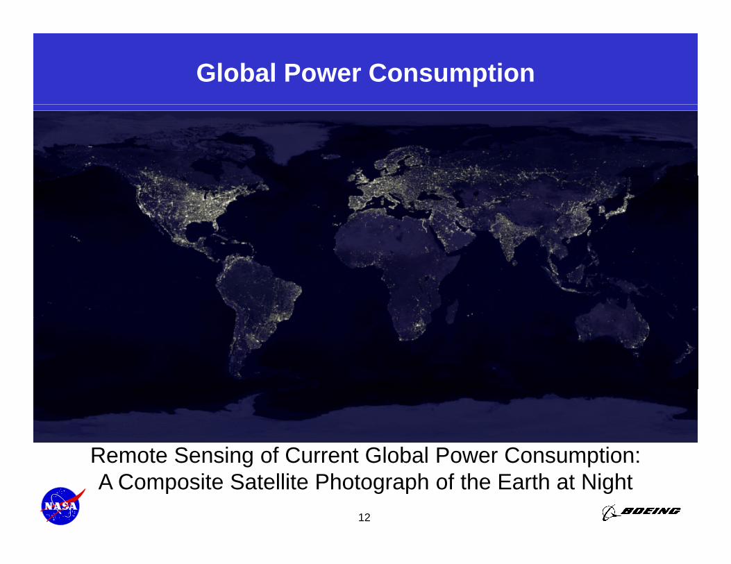
Global Power Consumption
Remote Sensing of Current Global Power Consumption:
12
Remote Sensing of Current Global Power Consumption:A Composite Satellite Photograph of the Earth at Night
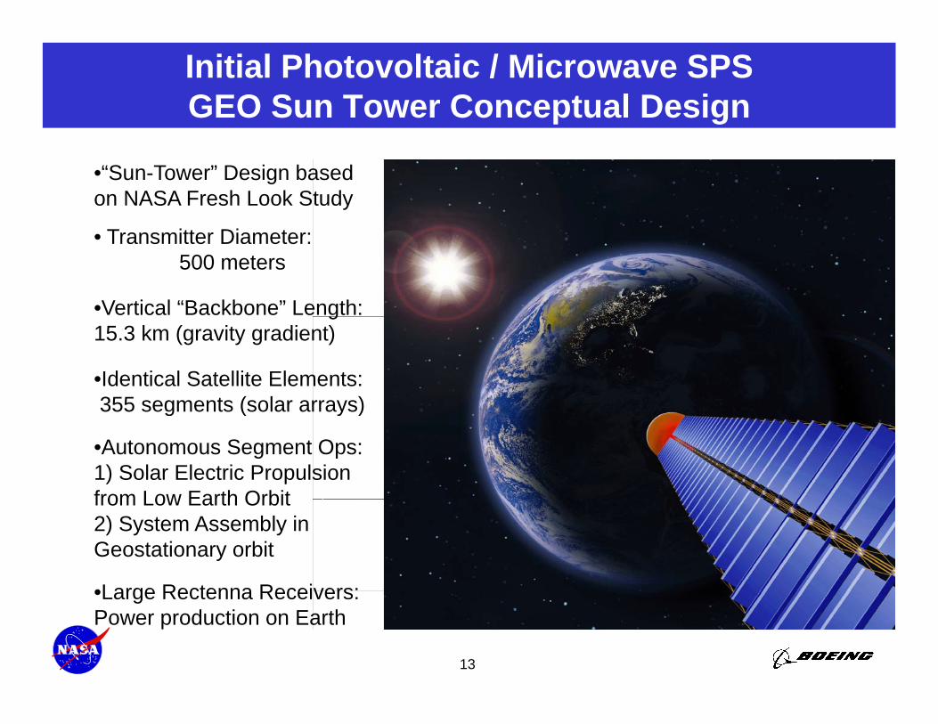
Initial Photovoltaic / Microwave SPSGEO Sun Tower Conceptual Design
•“Sun-Tower” Design based on NASA Fresh Look Study
• Transmitter Diameter: 500 meters
•Vertical “Backbone” Length: g15.3 km (gravity gradient)
•Identical Satellite Elements:355 segments (solar arrays)
•Autonomous Segment Ops: 1) Solar Electric Propulsion from Low Earth Orbit
355 segments (solar arrays)
from Low Earth Orbit2) System Assembly in Geostationary orbit
•Large Rectenna Receivers:
13
•Large Rectenna Receivers: Power production on Earth
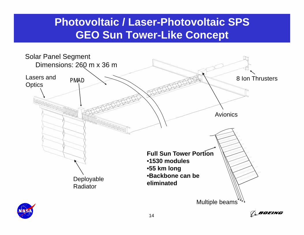
Photovoltaic / Laser-Photovoltaic SPSGEO Sun Tower-Like Concept
Solar Panel Segment Dimensions: 260 m x 36 m
8 Ion ThrustersLasers and Optics
PMAD
Avionics
Full Sun Tower Portion•1530 modules1530 modules•55 km long•Backbone can be eliminatedDeployable
Radiator
14
Multiple beams
Synergy Between Sunlight and Laser-PV WPTfor Terrestrial Photo-Voltaic Power Production
• Large photo-voltaic (PV) power plants in Earth’s major deserts (Mojave, Sahara, Gobi, etc.) receive & convert light from 2 sources:
1) Directly from the Sun and1) Directly from the Sun, and 2) Via WPT from SSP systems
• Laser light is transmitted and converted more efficiently than sun-lightW l th i l t d f d t h i t i i it– Wavelength is selected for good atmospheric transmissivity
– Efficient Light Emitting Diode wavelengths match common PV band-gaps • Gravity gradient-stabilized SPSs are in peak insolation at ~6 AM and
6 PM ith h d i i l t id d d id i ht~6 PM, with shadowing or cosine loss at mid-day and midnight– Heavy, complex gimbaled arrays add little extra power at these times– Both sides of rigid (not gimbaled) solar arrays can be light-sensitive
• Back-side produces less power due to occlusion by wires• Translucent substrate (e.g., Kapton) also reduces back-side power levels
– Even gimbaled arrays suffer a loss of power around noon and midnightTh bi ti f bi t li ht l l ill i ti bi
15
• The combination of ambient sunlight plus laser illumination combines, at the terrestrial PV array, to match the daily electricity demand pattern
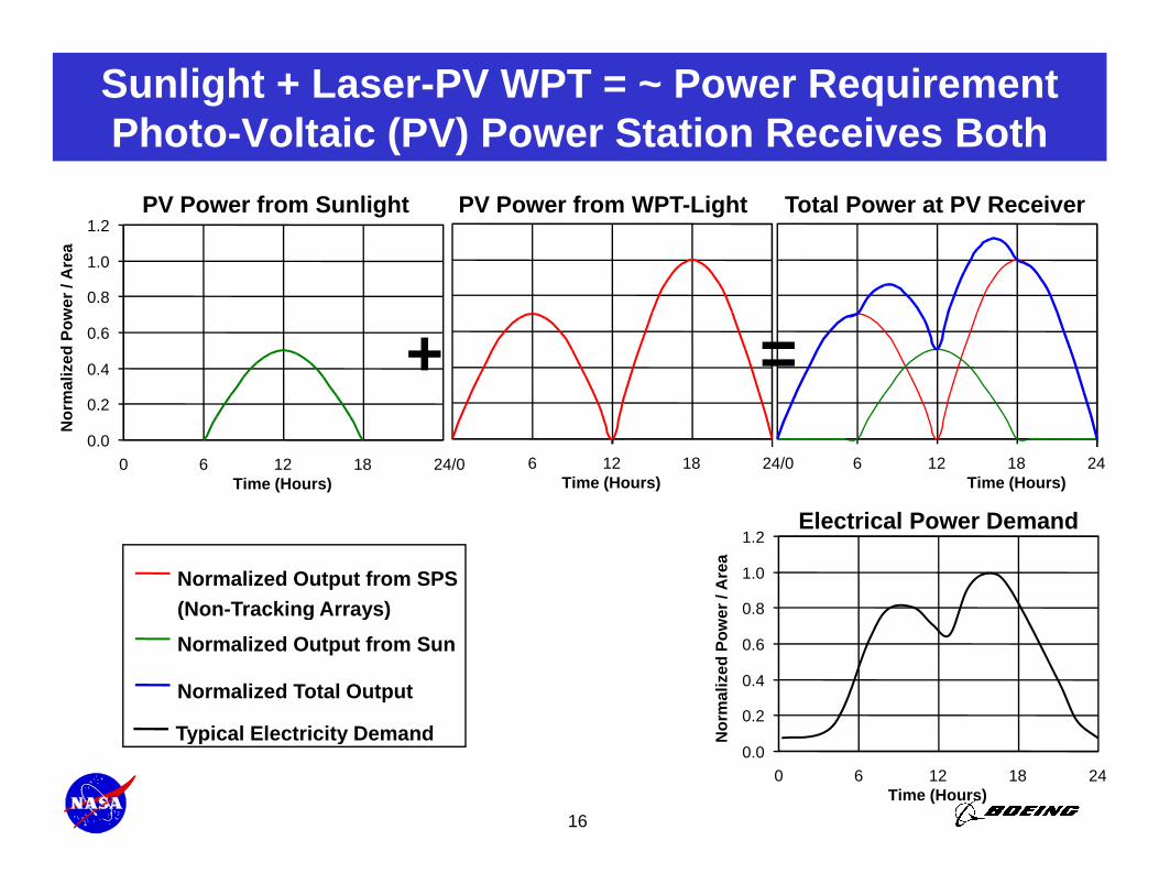
Sunlight + Laser-PV WPT = ~ Power RequirementPhoto-Voltaic (PV) Power Station Receives Both
1.0
1.2
Are
a
Total Power at PV ReceiverPV Power from WPT-LightPV Power from Sunlight
0.4
0.6
0.8
mal
ized
Pow
er /
A
+ =0.0
0.2
0 6 12 18 24/0Time (Hours)
Nor
m
6 12 18 24/0Time (Hours)
6 12 18 24Time (Hours)
Electrical Power Demand
Normalized Output from SPS(Non-Tracking Arrays) 0.8
1.0
1.2
er /
Are
a
( g y )Normalized Output from Sun
Normalized Total Output
Typical Electricity Demand0.2
0.4
0.6
orm
aliz
ed P
owe
1614
Typical Electricity Demand0.0
0 6 12 18 24Time (Hours)
No
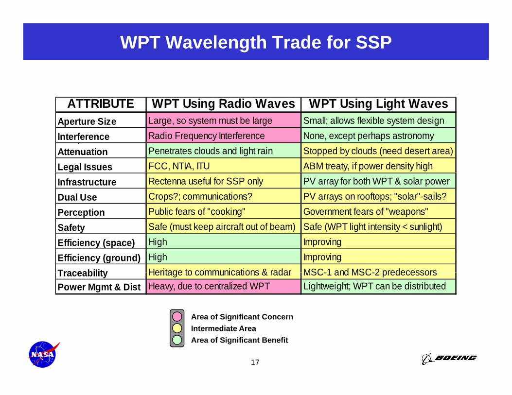
WPT Wavelength Trade for SSP
ATTRIBUTE WPT Using Radio Waves WPT Using Light WavesAperture Size Large, so system must be large Small; allows flexible system designAperture Size Large, so system must be large Small; allows flexible system designInterference Radio Frequency Interference None, except perhaps astronomy,Attenuation Penetrates clouds and light rain Stopped by clouds (need desert area)Legal Issues FCC, NTIA, ITU ABM treaty, if power density highInfrastructure Rectenna useful for SSP only PV array for both WPT & solar powerDual Use Crops?; communications? PV arrays on rooftops; "solar"-sails?Perception Public fears of "cooking" Government fears of "weapons"Safety Safe (must keep aircraft out of beam) Safe (WPT light intensity < sunlight)Efficiency (space) High ImprovingEfficiency (ground) High ImprovingTraceability Heritage to communications & radar MSC 1 and MSC 2 predecessorsTraceability Heritage to communications & radar MSC-1 and MSC-2 predecessors Power Mgmt & Dist Heavy, due to centralized WPT Lightweight; WPT can be distributed
Area of Significant Concern
17
Intermediate AreaArea of Significant Benefit
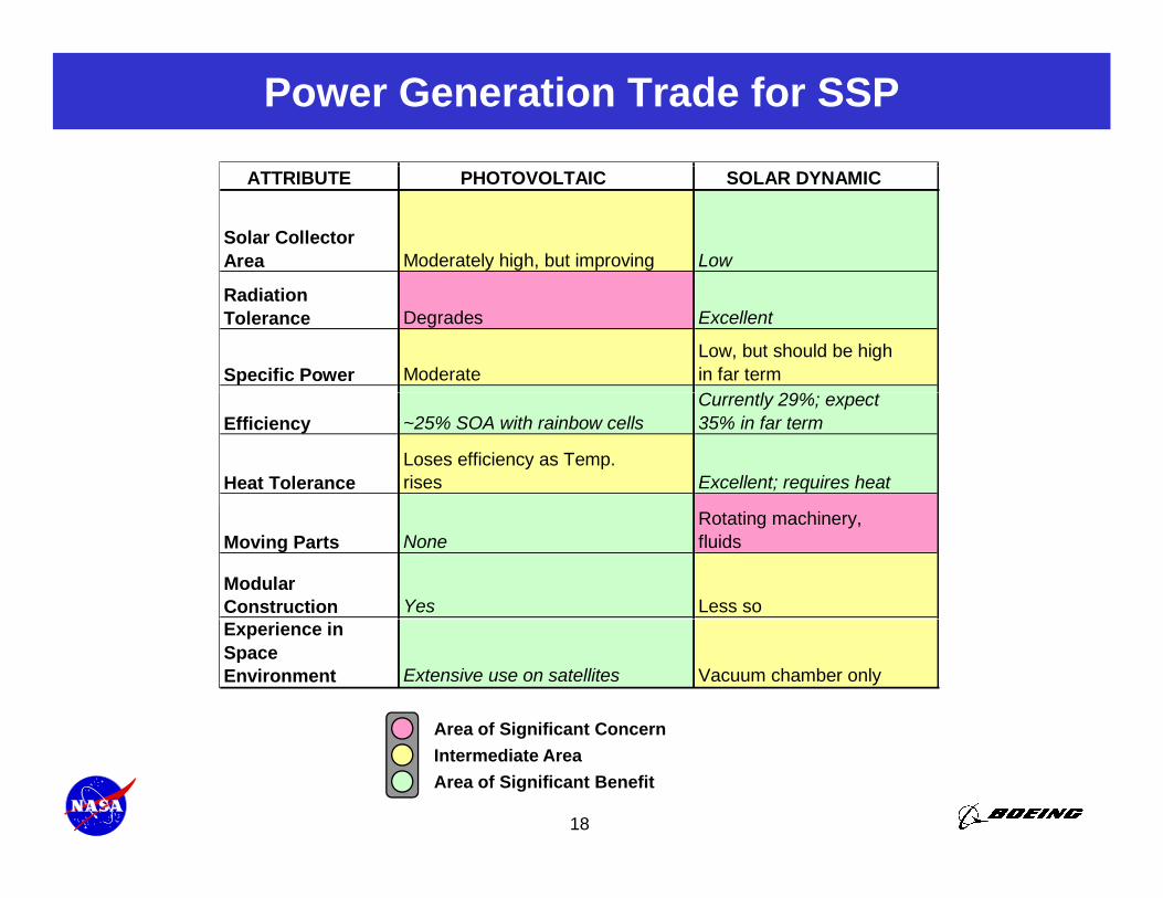
Power Generation Trade for SSP ATTRIBUTE PHOTOVOLTAIC SOLAR DYNAMIC
Solar Collector Area Moderately high, but improving Low
Radiation Tolerance Degrades Excellent
Specific Power Moderate Low, but should be high in far term C l 29%
Efficiency ~25% SOA with rainbow cells Currently 29%; expect 35% in far term
Heat Tolerance Loses efficiency as Temp. rises Excellent; requires heat
Moving Parts None Rotating machinery, fluids
Modular Construction Yes Less so Experience in Space Environment Extensive use on satellites Vacuum chamber only
Area of Significant Concern
18
Area of Significant ConcernIntermediate AreaArea of Significant Benefit
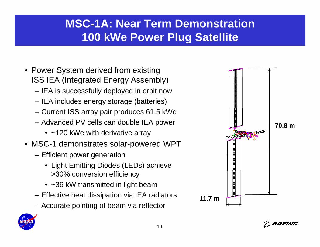
MSC-1A: Near Term Demonstration100 kWe Power Plug Satellite
• Power System derived from existing ISS IEA (I d E A bl )ISS IEA (Integrated Energy Assembly)– IEA is successfully deployed in orbit now– IEA includes energy storage (batteries)– Current ISS array pair produces 61.5 kWe– Advanced PV cells can double IEA power
• ~120 kWe with derivative array70.8 m
• MSC-1 demonstrates solar-powered WPT– Efficient power generation
• Light Emitting Diodes (LEDs) achieve >30% conversion efficiency
• ~36 kW transmitted in light beam– Effective heat dissipation via IEA radiators 11.7 m
19
– Accurate pointing of beam via reflector
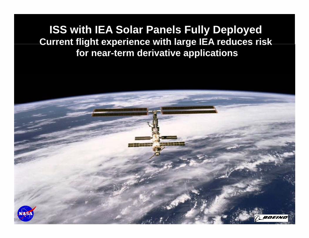
ISS with IEA Solar Panels Fully DeployedCurrent flight experience with large IEA reduces riskCurrent flight experience with large IEA reduces risk
for near-term derivative applications
20
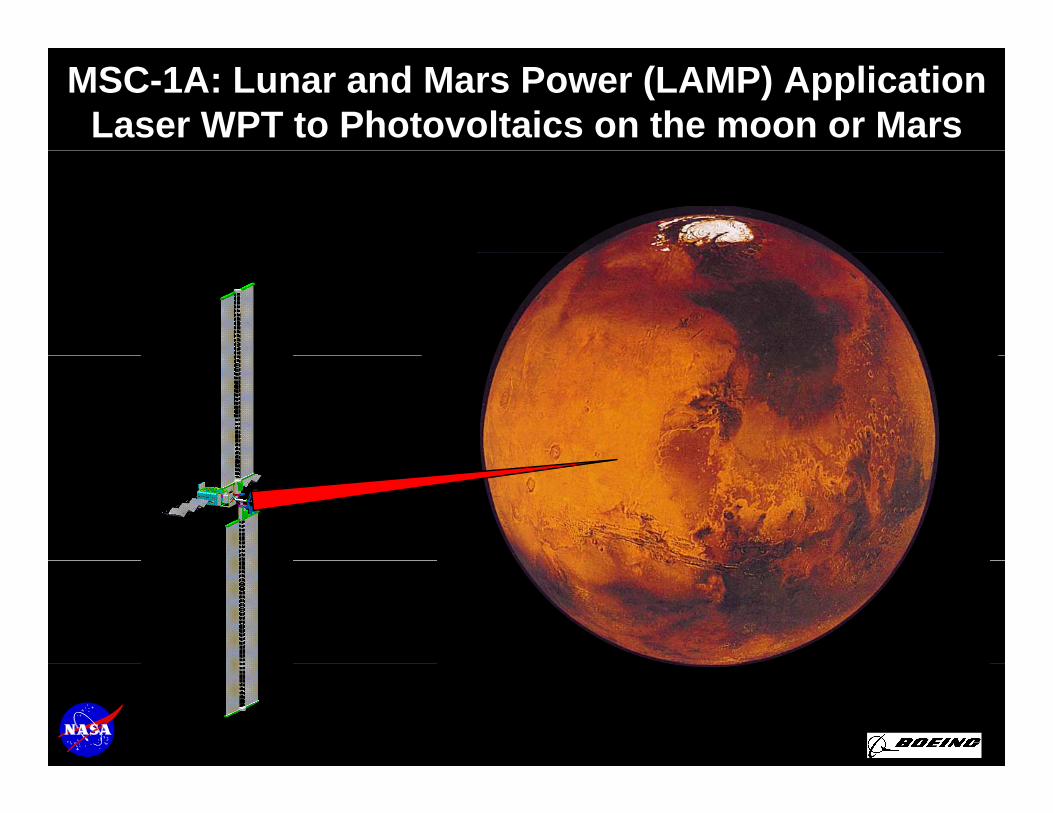
MSC-1A: Lunar and Mars Power (LAMP) ApplicationLaser WPT to Photovoltaics on the moon or Mars
21
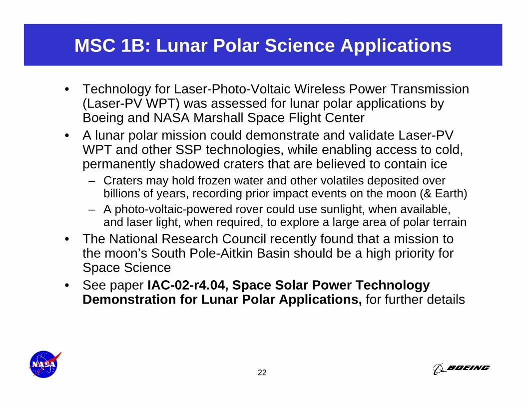
MSC 1B: Lunar Polar Science Applications
• Technology for Laser-Photo-Voltaic Wireless Power Transmission (Laser-PV WPT) was assessed for lunar polar applications by Boeing and NASA Marshall Space Flight Center
• A lunar polar mission could demonstrate and validate Laser-PV WPT and other SSP technologies, while enabling access to cold, permanently shadowed craters that are believed to contain ice
C t h ld f t d th l til d it d– Craters may hold frozen water and other volatiles deposited over billions of years, recording prior impact events on the moon (& Earth)
– A photo-voltaic-powered rover could use sunlight, when available, and laser light, when required, to explore a large area of polar terrain
• The National Research Council recently found that a mission to the moon’s South Pole-Aitkin Basin should be a high priority for Space ScienceS C 02 4 04 S S• See paper IAC-02-r4.04, Space Solar Power Technology Demonstration for Lunar Polar Applications, for further details
22
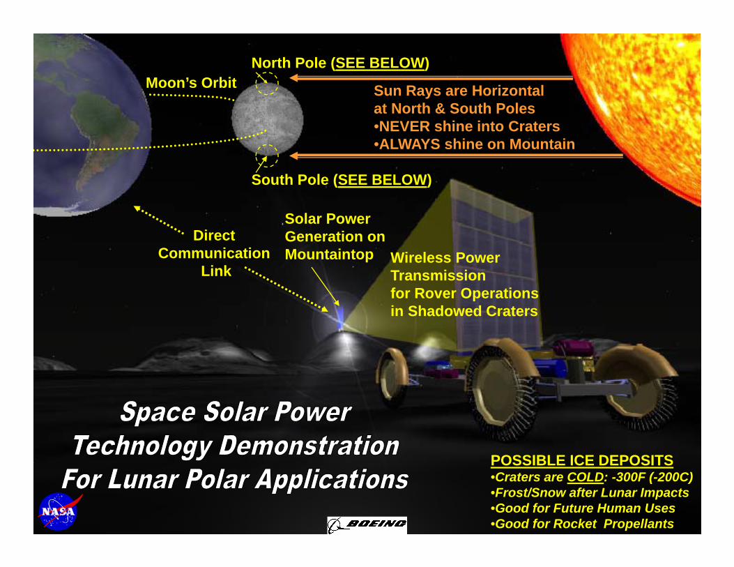
Moon’s OrbitNorth Pole (SEE BELOW)
Sun Rays are Horizontal t N th & S th P l
S th P l (SEE BELOW)
at North & South Poles•NEVER shine into Craters•ALWAYS shine on Mountain
Solar PowerGeneration on Direct
C i ti
South Pole (SEE BELOW)
Wireless Power Transmissionfor Rover Operationsin Shadowed Craters
MountaintopCommunicationLink
POSSIBLE ICE DEPOSITS
23
POSSIBLE ICE DEPOSITS•Craters are COLD: -300F (-200C)•Frost/Snow after Lunar Impacts•Good for Future Human Uses•Good for Rocket Propellants
Summary
• Farther-term micro-wave WPT options are efficient, and can beampower through clouds / light rain, but require large sizes for longdi t WPT d i li d i (“ t ”)distance WPT and a specialized receiver (“rectenna”).
• Nearer-term Laser-Photovoltaic WPT options are less efficient, butallow synergistic use of the same photovoltaic receiver for bothterrestrial solar power and SSPterrestrial solar power and SSP.
• Boeing is currently investigating near-term military, civil government,and commercial markets for SSP.
• Technology flight demonstrations can enable advanced space scienceTechnology flight demonstrations can enable advanced space science and exploration in the near term.
– “Power Plug” or “LAMP” spacecraft and Lunar Polar Solar Power outpost advance technology for far-term commercial SSP systems, while providing significant value for near term applicationssignificant value for near-term applications.
24
Acronyms• ABM = Antiballistic Missile• FCC = Federal Communications Commission• GEO = Geostationary Earth Orbit• IEA = Integrated Energy Assembly
ISS = International Space Station• ISS = International Space Station• ITU = International Telecommunications Union• km = kilometers• kWe = kilowatt electric• LAMP = Lunar and Mars Power• LED = Light Emitting Diode• LEO = Low Earth Orbit• m = meters\• m = meters\• MEO = Middle Earth Orbit• MSC = Model System Concept• NTIA = National Telecommunications and Information Administration• PMAD = Power Management and Distribution• PV = Photovoltaic• Rectenna = Rectifying Antenna• SPS = Solar Power Satellite
25
SPS Solar Power Satellite• SSP = Space Solar Power• WPT = Wireless Power Transmission