Embed Size (px)
Citation preview
/
/ " /
Study of NovelConcepts of PowerTransmission Gears
Final Report forNASA Grant NAG3-918
Period Covered:7/1/88 - 6/30/91
COLLEGEOFENGINEERING
Principal Investigator:Eugene I. Rivin, ProfessorDepartment of MechanicalEngineeringWayne State UniversityDetroit MI 48202
Wc_/neStateUrdversity
I
............ i_ .I ', " _r'.,
Lit, iv. ] ',:b ,, 4',_ t. I_.
/._ ?
Ur_ t_ 1
.I
https://ntrs.nasa.gov/search.jsp?R=19920007103 2020-03-25T01:20:03+00:00Z
TABLE OF CONTENTS
Summary 1
Chapter 1. Introduction and State of the Art 2
I. 1. Novel Concepts in Power Transmission Gear Design 3
1.2. Goals of the Project 5
Chapter 2. Thin-Layered Rubber-Metal Laminates 6
2.1. Static Characteristics 6
2.1.1. Test System 6
2.1.2 Experimental Results 7
2.2. Dynamic Properties of Laminates 11
2.2.1 Laminates with Hard Rubber Have the Best
Dynamic Properties 11
2.2.2 Relationship between Dynamic Stress and StaticUltimate Stress 11
2.2.3 Effect of Surface Area of Laminates on Dynamic
Properties 12
2.2.4 Elastic Stability and Buckling Stress of Small AreaLaminates 12
2.2.5 Influence of Rubber Material 13
2.2.6 Heat Buildup in Laminates under Dynamic Load 14
Chapter 3. Enhancement of Load-Carrying Capacity of Laminate-CoatedConformal Gears 15
3.1. Strength Calculation of Symmark Gears 16
3.1.1 Bending Stress 16
3.1.2 Contact Stress 17
3.2. Calculation of Sliding distance 18
3.3. Analysis of Profile Surface of Conformal Gear 19
3.3.1 Formulas for Calculating Curved Surfaces ofConformal (Novikov) Gear 19
3.3.2 Formulas for Calculating Oblique Cylinder Surface 21
3.4.Designof Special Laminate Pieces
3.5. Test Arrangement and results
3.5.1 Rotation Tests
3.5.2 Vibratory Tests
3.6. Improving Laminate-Coated Tooth Profile
Chapter 4. Composite Gear
4.1 Meshing Conditions of Composite Gear System andGeneration of Teeth Profiles
i 4.2. Design of the Composite Gear
4.2.1 Design Parameters of Prototype Composite Gears
4.2.2 Structural Design of Prototype Composite Gear
4.2.3 Strength Calculations
4.3. Approximation of External Surface of Tooth Segmentsby Circular Arcs
4.4. Testing of Laminated Bushings
4.4.1 Torsional Stiffness of Laminated Bushing
4.4.2 Compression Stress and Compression Modulus
4.4.3 Fatigue Life
4.5. Tests of Composite Gears
Conclusions
References
Tables
Figures
Appendix 1. Study of Meshing Conditions of a Novel Gear System
23
23
23
24
25
26
26
26
26
27
27
30
31
31
31
31
31
32
32
35
53
78
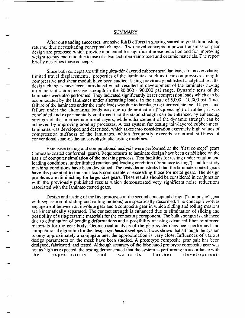
SUMMARY
After outstanding successes, intensive R&D efforts in gearing started to yield diminishingreturns, thus necessitating conceptual changes. Two novel concepts in power transmission geardesign are proposed which provide a potential for significant noise reduction and for improving
weight-to-payload ratio due to use of advanced fiber-reinforced and ceramic materials. The reportbriefly describes these concepts.
Since both concepts are utilizing ultra-thin-layered rubber-metal laminates for accomodatinglimited travel displacements, properties of the laminates, such as their compressive strength,compressive and shear moduli have been studied. Using previously published analytical results,design changes have been introduced which resulted in development of the laminates havingultimate static compressive strength in the 80,000 - 90,000 psi range. Dynamic tests of thelaminates were also performed. They indicated significantly lesser compression loads which can beaccomodated by the laminates under alternating loads, in the range of 5,000 - 10,000 psi. Sincefailure of the laminates under the static loads was due to breakage og intermediate metal layers, and
failure under the alternating loads was due to delamination ("squeezing") of rubber, it wasconcluded and experimentally confirmed that the static strength can be enhanced by enhancingstrength of the intermediate metal layers, while enhancement of the dynamic strength can beachieved by improving bonding processes. A test system for testing thin-layered rubber-metallaminates was developed and described, which takes into consideration extremely high values ofcompression stiffness of the laminates, which frequently exceeds structural stiffness ofconventional state-of-the-art servohydraulic testing machines.
Extensive testing and computational analysis were performed on the "first concept" gears(laminate-coated conformal gears). Requirements to laminate design have been established on thebasis of computer simulation of the meshing process. Test facilities for testing under rotation andloading conditions; under limited rotation and loading condition ("vibratory testing"), and for studymeshing conditions have been developed. The tests demonstrated that the laminate-coated gearshave the potential to transmit loads comparable or exceeding those for metal gears. The designproblems are diminishing for larger size gears. These results should be considered in conjunctionwith the previously published results which demonstrated very significant noise reductionsassociated with the laminate-coated gears.
Design and testing of the first prototype of the second conceptual design ("composite" gearwith separation of sliding and rolling motions) are specifically described. The concept involvesengagement between an involute gear and a composite gear in which sliding and rolling motionsare kinematically separated. The contact strength is enhanced due to elimination of sliding andpossibility of using ceramic materials for the contacting component. The bulk strength is enhanceddue to elimination of bending deformations and a possibility of using advanced fiber-reinforcedmaterials for the gear body. Geometrical analysis of the gear system has been performed and
computational algorithm for the design synthesis developed. It was shown that although the systemis only approximately a conjugate one, the approximation is very close. Influences of variousdesign parameters on the mesh have been studied. A prototype composite gear pair has beendesigned, fabricated, and tested. Although accuracy of the fabricated prototype composite gear wasnot as high as expected, the testing demonstrated that the system is performing in accordance withthe expectations and warrants further development.
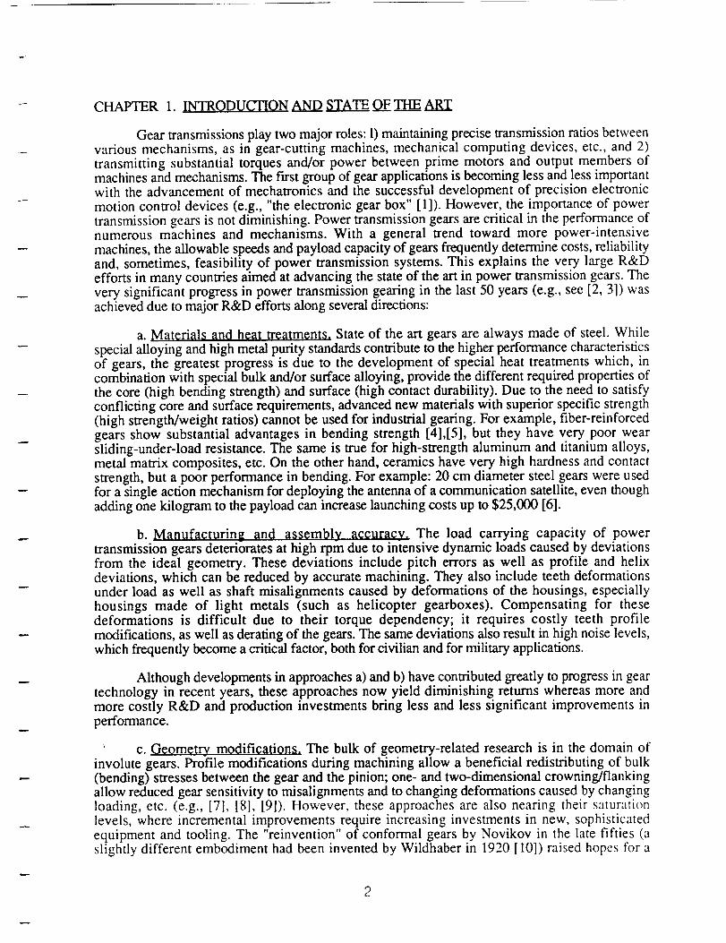
CHAPTER 1. INTRODUCTIONAND STATE OF THE ART
Gear transmissions play two major roles: 1) maintaining precise transmission ratios betweenvarious mechanisms, as in gear-cutting machines, mechanical computing devices, etc., and 2)transmitting substantial torques and/or power between prime motors and output members ofmachines and mechanisms. The first group of gear applications is becoming less and less importantwith the advancement of mechatronics and the successful development of precision electronic
motion control devices (e.g., "the electronic gear box" [ 1]). However, the importance of powertransmission gears is not diminishing. Power transmission gears are critical in the performance ofnumerous machines and mechanisms. With a general trend toward more power-intensive
machines, the allowable speeds and payload capacity of gears frequently determine costs, reliabilityand, sometimes, feasibility of power transmission systems. This explains the very large R&Defforts in many countries aimed at advancing the state of the art in power transmission gears. Thevery significant progress in power transmission gearing in the last 50 years (e.g., see [2, 3]) wasachieved due to major R&D efforts along several directions:
a. Ma_ri01s and heat treatments. State of the art gears are always made of steel. Whilespecial alloying and high metal purity standards contribute to the higher performance characteristicsof gears, the greatest progress is due to the development of special heat treatments which, incombination with special bulk and/or surface alloying, provide the different required properties ofthe core (high bending strength) and surface (high contact durability). Due to the need to satisfyconflicting core and surface requirements, advanced new materials with superior specific strength(high strength/weight ratios) cannot be used for industrial gearing. For example, fiber-reinforcedgears show substantial advantages in bending strength [4],[5], but they have very poor wearsliding-under-load resistance. The same is true for high-strength aluminum and titanium alloys,metal matrix composites, etc. On the other hand, ceramics have very high hardness and contactstrength, but a poor performance in bending. For example: 20 cm diameter steel gears were usedfor a single action mechanism for deploying the antenna of a communication satellite, even thoughadding one kilogram to the payload can increase launching costs up to $25,000 [6].
b. Manuf0cturing and assembly accuracy. The load carrying capacity of powertransmission gears deteriorates at high rpm due to intensive dynamic loads caused by deviationsfrom the ideal geometry. These deviations include pitch errors as well as profile and helixdeviations, which can be reduced by accurate machining. They also include teeth deformationsunder load as well as shaft misalignments caused by deformations of the housings, especially
housings made of light metals (such as helicopter gearboxes). Compensating for thesedeformations is difficult due to their torque dependency; it requires costly teeth profile
modifications, as well as derating of the gears. The same deviations also result in high noise levels,which frequently become a critical factor, both for civilian and for military applications.
Although developments in approaches a) and b) have contributed greatly to progress in geartechnology in recent years, these approaches now yield diminishing returns whereas more andmore costly R&D and production investments bring less and less significant improvements in
performance.
c. Geometry_ modifications. The bulk of geometry-related research is in the domain ofinvolute gears. Profile modifications during machining allow a beneficial redistributing of bulk(bending) stresses between the gear and the pinion; one- and two-dimensional crowning/flankingallow reduced gear sensitivity to misalignments and to changing deformations caused by changingloading, etc. (e.g., [7], [8], [9]). However, these approaches are also nearing their saturationlevels, where incremental improvements require increasing investments in new, sophisticatedequipment and tooling. The "reinvention" of conformal gears by Novikov in the late fifties (aslightly different embodiment had been invented by Wildhaber in 1920 [10]) raised hopes for a
2
dramaticbreakthroughin geartechnologydue to the theoreticallyhigherstrengthof conformalWildhaber/Novikov(W/N) gears.However,thesehopesfadedafter it wasdiscovered,that highnoiselevelsandhighsensitivitytocenterdistancedeviationsareverydifficult to abate.
Main problemspreventingawiderapplicationof the conformal gears are their sensitivity tocenter distance variation; high rigidity of the "squat" teeth causing very high dynamic loads as wellas vibration and noise levels even at moderate speeds; impossibility of grinding the tooth surfaces
by a generating method, only by a contoured wheel which complicates use of hardened gears [ 11].
A generic problem for all types of power transmission gears is noise, which becomes moreand more of a determining factor for assigning the machining/assembly tolerances for gears and,thus, for their costs. In some cases noisy gears require additional and very costly acoustical
treatments, even when gears are produced to a high degree of accuracy (e.g., in submarines and"low noise" helicopters). Numerous effective techniques for noise abatement, such as plastic ormetal-polymer gears, gears with rims insulated from the hubs, (e.g. [12]), etc., are usuallyassociated with substantial derating.
Although the power transmission efficiency of state of the art gears is quite high (up to andeven exceeding 0.99), in cases when multi-stage or planetary gear trains are used, their overallefficiency can be as low as 0.85-0.90. Such values are typical, for example, in vehicles, and causesecondary weight and power consumption penalties (e.g., associated with the need to use largerengines and supporting structures, etc.). Although energy losses are generated not only in gearsbut also in other components of the transmission (bearings, lubrication systems, etc.), up to 80%of the losses are due to the gear mesh itself [13]. Reduction of the losses in conventional gearsrequires more stringent tolerances and thus is associated with high costs.
Summarizing, the following major problems should be addressed to upgrade the state ofthe art of power transmission gearing in response to design needs in high-technology mechanical
design:
- Radical increase in payload capacity.
- Radical reduction in noise levels of heavy duty high-speed gear transmissions.
- Development of low weight power transmissions.
- Cost containment for high grade gears.
- Reduction of energy losses.
1.1 NOVEL CONCEPTS IN POWER TRANSMISSION GEAR DESIGN
As noted above, after about 50 years of continuous improvements in gear state of the art, a"saturation" period is now approaching when larger expenses on R&D bring diminishing returns inimproved performance. Usually, this is a time for conceptual changes in the technology. Recentlywe proposed development of two novel concepts in power transmission gear designs. Bothconcepts are based on the principles of separation between rolling and sliding processes duringengagement between the meshing teeth. Such separation results in elimination of the need for atooth surface to endure high contact loads together with sliding.
The _ concept [14], [15] involves elimination of physical _ between the meshingtooth profiles, and accommodation of inevitable geometric _ by internal shear in thin-layeredmetal-elastomer laminates attached to the profile(s), Fig.l.1. Recent research results, partlydescribed in [ 16], have shown that, due in part to volumetric incompressibility of elastomeric
3
(rubber-like)materials,thethin-layeredlaminateshavearelativelyhighcompressionmodulus(upto 2,500MPa),andvery high compressivestrength(up to andexceeding200-300MPa).At thesametime,their shearmodulusis very low (for soft elastomers,optimal for theapplicationsunderdiscussion, G = 0.5-0.7 MPa). Another important property of the laminates is a virtualindependenceof their resistanceto sheardeformationfrom compressiveforces(asopposedtofrictional joints).Dependingon therubberblenda relativeshearof 50-75%is toleratedfor rubberpartsunderrepeatedsheardeformation(e.g.,[17]).
Theuniquecharacteristicsof thin-layeredmetal-elastomerlaminatesareutilizedin severalengineeringapplications,includingsuchcriticalapplicationsaslimited-travelbearingsinhelicopterrotor hubs[18],torsionally-rigidmisalignmentcompensatingcouplings[19], etc.Theapplicationof laminatesto powertransmissiongearsis madepossibleby thefact thatthetotal sliding travelbetweenthemeshingprofilesduringonecycleof engagementis limited.
An importantissueis thecontact(surface)strengthof thelaminate-coatedgears.While stateof the art materials/heattreatmentsallow contactpressuresup to 1,300MPa (e.g., [20]), thelaminatesallow only 200-300MPa [16]. However, actualcontactstresseson surfacesof thelaminate-coatedgearsaregreatlyreduceddueto a lessercompressionmodulusof thelaminatesandthusto distributionof the loadacrossalargerareaof contact.Theadvantagesof thelaminate-coated gears in effective bending strength are enhanced,for a given center distance andtransmissionratio,with increasingtoothsize(thus,reducingteethnumber).Therearetworeasonsfor this:1)with increasingtoothsize,theoverall thicknessof elastomerin the laminateshouldbeincreased,but not the thicknessof the facemetal layer; 2) for the larger teeththe numberoflaminatesegmentscanbeincreased,thuseffectivelyreducingthetotal thicknessof the coating.Asteepreductionin thenumbersof teethcanbenaturallyachievedin conformal(W/N) gears,inwhich Z = 3-5canbeeasilydesigned[21]. Thelaminatecoating,due to its local compliance,alleviatesthebasicdeficienciesof W/N gears-sensitivity to centerdistancevariationsandhighdynamic load/noise generation. Becauseof it, additional bending and surface strengthenhancementsinherentin W/N gears(e.g.,see[22]) canbeutilized. This would furtheradvancethe artof geardesign.It wasshownin [23] thatnoiseof thecoatedW/N gearsis reducedby 15-20dB.
Dueto thebeneficialeffectsof the laminatecoatingonbothsurfaceandbendingstrengthofgears, and also due to separation between the componentsof the gear responsible foraccommodatingbendingandcontactloading,laminate-coatedgearscanutilizecoresmadeof lightbut strongmaterials.Thesecanbe aluminumor titanium alloys, or compositefiber-reinforcedmaterials,asin [4], [5].
An advantageof W/N gearsfor applicationof this conceptis theconstancyof curvatureradii of thecircularcrosssectionin conformaltoothprofiles,Fig.1.2.As aresult,accommodationof theslidingpathbythelaminatecoatinginvolvesonly puresheardeformationin thelaminate.Onthe otherhand,the curvatureradiusof the involute profile is constantlychanging,increasingtowards the tooth addendum.Thus, sheardeformation during accommodationof sliding isaccompaniedby the changingcurvatureof the laminate, that is, by somebendingandthus bycompressionin thelaminate.Althoughthedegreeof thecurvaturechangeis alleviateddueto thesegmentingof the coating, even minor compressionsignificantly increasesthe deformationresistanceof the laminatesdue to the hugedifferencesbetweentheir compressionand shearmoduli.
If bothprofiles of the teethof at leastoneof the engaginggearshavethe elastomericcoating,thenthemeshcanbepreloaded.With suchanarrangementthebacklashis eliminated,butsliding resistancebetweentheteeth(andenergylosses)arenot increasingsincetheshearmodulusof a thin-layeredmetal-elastomerlaminatedoesnot dependon thecompressionload [16]. Someincreasein losseswould occur in bearingsdue to additional radial forceson the shaftsof the
z_
preloadedgears,but this is only asmallfractionof thelossesincurredin conventionalpreloadedanti-backlashgears,suchasin [15].The independenceof shearmodulusfromcompressiveloadsalsoresultsin the improvedefficiencyof thelaminate-coatedgears.
Sincelossesin thelaminatesdonot dependon thecompressiveloading,efficiencyof suchgearsathighpayloadsis expectedto bebetterthanfor conventionalgears.
The second q9ncept is applicable to involute gears.It suggests resolution of the combinedrolling-sliding motion between the engaging involute teeth into pure sliding and pure rolling [24].A so-called "composite gear" is meshing with an involute gear. Pure rolling occurs between theinvolute profile of one tooth and a specially synthesized profile of a special "crescent" which, inturn, slides along the circular cylindrical surface of the tooth core of the counterpart "composite"tooth.
To achieve this effect, each tooth of at least one of the gears (12a in Fig.l.3) is composedof: tooth core 14 with a circular convex profile 20, crescent 18 with an internal concave circularprofile matching convex profile 20 of core 14, and external profile constructed in such a way thatwhen it is meshing in a rolling motion with an involute tooth 15, a conjugate action ensues. Thus,the gear pair 12a-12b is equivalent to a pair of involute gears. It was shown [25] that externalprofile of 18 can be synthesized by a simple geometric/computational procedure to beapproximately conjugate with an involute gear.
Any known type of bearing can be used to accommodate sliding between tooth core 14 andcrescent 18, such as a conventional lubricated or a hydrostatic bearing, rolling bodies, springs,metal-elastomer laminates, etc. The latter two techniques seem to be preferable, since they combineaccommodation of the required limited motion with automatic return of crescent 18 to its initialposition and with keeping it in a proper configuration. Although other design means can be used toachieve the same results, internal friction connections seem to be the most effective means. Theyalso result in a superior efficiency.
It is very important to note that the crescent is subjected to compression force only,Fig. 1.4a, contrary to conventional involute gears in which teeth are subjected to bending loadingwith a significant tensile stress in the fillet area, Fig. 1.4b. Since the compression load is applied ina purely rolling mode, without sliding,the crescent can accomodate much higher loads even if it ismade of the conventional gear materials. It is shown in [26] that the allowable contact stress in caseof simultaneous rolling and sliding action between the contacting bodies is only about 50% of theallowable stress for a pure rolling contact for the same reference number of stress cycles. Inaddition, since there are no tensile stresses in the crescent, it can be fabricated from materials
having superior strength in compression and contact endurance (e.g., ceramics). The tooth core(and the gear body) can be made of a light material which has high bulk strength (e.g., fiberreinforced composites) since the loads are applied to the tooth core in a distributed mode.
1.2 GOALS OF THE PROJECT
This project had as its goals a detailed study of engagement processes in both novelconceptual designs of power transmission gears, a study of static and dynamic characteristics ofthin-layered rubber-metal laminates and ways to improve their performance; design of an actualgear pair for a performance testing.
5
CHAPTER2. THIN - LAyERED RUBBER - METAL LAMINATES
2.1 STATIC CHARACTERISTICS
Elastomeric (rubber-like) materials are practically incompressible, their degree of
compressibility being dependent on small deviations of Poisson's ratio v from the ideal value of v
= 0.5. Thus, compression under a force Pz of a cylindrical rubber element 1 in Fig.2. la, which isbonded to metal end plates 2, 3, can occur only due to bulging of element 1 on its free surfaces. Ifan intermediate metal layer 4 is placed in the middle of and bonded to the rubber element 1 as in
Fig.2. lb, thus dividing it into two layers 1' and 1 ", then the bulging is restricted and compression
deformation with the same Pz is reduced. While the compression stiffness for a given total heightof the rubber element can be varied in a broad range by means of selecting a number of metalinterleaves, the shear stiffness in the direction of horizontal force Px remains constant since sheardeformation is not associated with a volume change. Thus, the best properties of the rubber-metal
laminates for applications as limited travel bearings can be expected for very thin rubber layers,when stiffness in the compression direction can be made very high without increasing their shearstiffness.
Actual properties of ultra-thin layered rubber-metal laminates are influenced by deviationsof n from 0.5; by effects of adhesive layers; deformations in metal interleaves; nonlinearity. Adetailed study of properties of ultra-thin layered rubber-metal laminates is described in [ 16]. The
material has a remarkable strength. It was shown in [16] that the compressive strength of laminatesis as high as 200-300 MPa (30-45,000 psi), and that their failures always started in the metalinterleaves, not in the rubber. It was shown analytically, that the maximum stress in the metalinterleaves of a round laminate is
o = pz/2[hr/hm(1-v) + v + (hr/h m + vhr/hm-v + 2)/¢], (2.1)
where: hr-thickness of rubber layer; hm- thickness of metal layer; ¢ = 1- 2Ii(aR)/[aR)Io(aR)];
= 12G/Khr2; G, K -shear modulus, volumetric compressibility modulus of rubber, R - externalradius of the laminate; Io, I1 - modifified Bessel functions.
In order to use laminate on the concept gears under investigation, static properties of thelaminates such as compression modulus, ultimate compression stress, shear modulus, relationshipbetween stress and strain should be known. For ultrathin-layerd laminates with strain larger than1%, the compression stiffness is nonlinear, no close-form solutions [besides expressions forstresses, like (2.1)] for this case are known; finite element analysis is difficult due to significantinfluence of the bonding (glue) layers. In this project,experimental studies were performed tofurther evaluate mechanical properties of the laminates.
2.1.1 Test System
Fig.2.2 shows the test set-up for load-deformation tests. In this Figure: INSTRON is aelectrohydraulic testing machine (Instron mod, 1351) which can provide 0-20,000 lb static anddynamic load in the frequency range 0-100 Hz; LVDT is a linear variable differential transformer
which was used to measure static and dynamic displacements in the range 0.001-0.25 in.INSTRON "stroke" readout shows the total deformation of the sample and the actuator syster_.and the machine frame. In conventional cases, deformation of the actuator system and frame couldbe neglected and the readout is adequately representing deformation of the specimen. However,
6
deformations of a ultrathin-layered laminates are very small and deformations of the actuatorsystem and frame could not be neglected [16]; LOAD CELL is a part of the testing machine; it
measures the load applied to the laminate; Nicolet mod 4094 digital oscilloscope was used toobserve, record and transmit to a PC the test data on both load and deformation.
2.1.2 Experimental Results
Important static characteristics of the laminates include compression stiffness, compressionmodulus, ultimate compression stress and strain, shear stiffness and modulus. All of theseparameters have to be considered when a laminate is applied to the gear teeth as a load-carryingcomponent.
According to reference [16] , the following formulas were used to calculate thecompression modulus Ec and the shear modulus G from the load- deformation experimentresults:
Ec = A(_zhrgAz,
where:
Aoz is increment of compression stress;
hri is total thickness of rubber, which varies during loading process;
Az is increment of the compression deformation;
(2.2)
G = AOxhrAx (2.3)
where:
A_ x is increment of the shear stress;
Ax is increment of the shear deformation.
2.1.2.1 Compression Modulus and Ultimate Compression Stress
At first, the compression load-deformation tests were performed. Test specimens werechosen using different rubber materials such as neopren rubber, natural rubber, and latex rubber,different thicknesses of rubber layers, and different surface areas. From test results shown inTables 2.1, 2, 3, Figs.2.3 a,b,c,d the following conclusions could be obtained.
(1) Compression Modulus and Ultimate Compression Stress
Table 2.1 and Fig.2.3a show the results of compression load-deformation tests for sixdifferent samples A, B, C, D, E, F which have the same design (two layers of rubber andthree layers of steel, the thickness of each layer of steel sheet is 0.002 inch, were bonded togetherby the Loctite Black Label glue), same square area ( About 0.1 sq.in). Rubber materials of samplesare different and their thicknesses varied from 0.01 inch to 0.05 inch. The rubber of specimens
B, C, and D is natural rubber with Shore durometer 30, 40, 40, respectively; A was made ofNeoprene rubber;, and E, F - from latex rubber. All specimens demonstrated very high ratios ofcompression stiffness to shear stiffness (up to 1000-2600 times) and very high ultimatecompression stresses. For the sample C, in which thickness of rubber layers is 0.01 in. (thethinnest), compression modulus (E=158,000 psi) is about 0.2% of that for steel and ultimatecompression stress (S=54,000 psi) is close to one third of that for steel. Also, Table 2.3 indicates
that for sample G5, in which thickness of the intermediate steel layer is increased from 0.002 inchto 0.004 inch, the surface area of the laminate is increased from 0.1 to 0.16 sq.in and there are four
7
layersof rubber,themaximumcompressionmodulusis E--481,600 psi which is close to 1.5% ofthe Young's modulus for steel and the ultimate compression stress is S=117,000 whichapproaches ultimate stress for steel. These results are encouraging for application of the laminatesas load-carrying components attached to the gear teeth.
(2) Ultimate Compression Strain
The ultimate compression strains for samples A, B, C, D are about 0.3 and for E and Fare about 0.55, as shown in Fig.2.4. Generally, the maxmimum allowable compression strain fornatural rubber is 0.35 and higher strains are allowable for latex rubber. The thinner is the rubber
layer, the higher the stiffness of the laminate.
(3) Effect of Intermediate Metal Layer on Compression Modulus
Thickness of the intermediate metal layers has remarkable effect on static properties of thelaminates. In Table 2.2, two samples D and D7 have the same structure except for differentthicknesses of the intermediate steel layer: the 0.002inch thickness for D and 0.002*2=0.004 in.for D7. The test results in Table 2.2 show that the compression modulus of D7 is 4 times that ofD and the ultimate compression stress is 2 times of that of D. The same conclusion can beobtained from Table 2.3. Samples G3, G4, G5, have the same four layers of rubber and the same
surface area 0.16 sq.in , but different thicknesses of intermediate and top metal layers. G3 has thethicknesses of intermediate steel layers 0.002 in., G4 and G5 - 0.002"2=0.004in.. The thickness
of top steel layers for G3 and G4 is 0.002"5=0.010 in., for G5 0.002"10=0.02 in.. Thecompression modulus of G4 is 2 times that of G3 and compression ultimate stress - 2.5 times ofG3. The compression modulus of G5 is only 1.1 times that of G4. These test results are
corresponding well with formula (2.1) from Biderman [27].
(4) Effect of Shape Factor on Compression Modulus
The compression modulus of laminates is correlated with the shape factor S [28] which isthe ratio of surface areas of one loaded surface and the load-free surface. For our square sample,
the formula for calculating S is as follows:
S = a2/4at = a/4t, (2.4)
where a is side length of square, and t is thickness of one rubber layer.
In this formula, there are two parameters - thickness of one layer of rubber and surface areaof laminate, which effect the shape factor. The effect of thickness of a rubber layer is shown inTable 2.1 and Fig.2.3(a). Samples C and D have the same structure except for the thickness of
rubber layers; namely, the thickness of the rubber layers for C is half of that for sample D andthe shape factor S of C is 8.4 and the shape factor S of D is 4.3. As a result, the compressionmodulus and ultimate compression stress of the sample C are twice these for D. Similarly, thethickness of the rubber layers of the sample E is 60% of that of F, shape factor SE = 2.7 and SF= 1.5, resulting in compression modulus and compression ultimate stress of the sample E being120% of that of F. Thus, the thinner the thickness of each layer of rubber, the higher the
compression stiffness and the ultimate compression stress.
The effect of surface area of laminates can be observed in Figs.2.3(b) and (c). Two
samples have the same structure (three layers of rubber 0.015inch thick, thickness of a steel laveris 0.012inch) but different area. For the ratio of their areas 1.5 (the ratio of the shape factors 1.2)the maximum compression modulus and ultimate stress are increasing 1.5 times and 1.75 times
respectively. It shouldbenotedthat thereis no apparenteffectof the laminate area in the smallstrain range (linearity range of stress-strain relationship) as shown in Fig.2.3(b), (c).
(5) Effect of Rubber Materials on Compression Modulus
The rubber materials also affect the static properties of laminates. Specimens E and Fhave shape factors, respectively, 2.7 and 1.5, which are smaller than the 4.7 for B and 4.3 forD. Although they have the same surface areas and other structural perameters, the compressionmoduli and ultimate compression stresses of the specimens with latex rubber are almost twice ofthose for B and are equal to ones for D. This is because the latex rubber is a very pure rubber
and its Poisson's ratio is almost equal to 0.5.
2.1.2.2 Shear Modulus of Laminates
The shearing load-deformation test system is shown in Fig.2.5 in which compressionloading surfaces are round to simulate the tooth profiles. All test results are shown in Fig.2.6, 7,8, 9, 10. Fig.2.6 shows shear modulus vs. shear stress for six samples which are the samesamples whose perameters were described above. Three conclusions can be fomulated:
(1) Shear Modulus G Is Equal to 1/3 of Young's Modulus
According to elasticity theory
G = E/2(1-v) = E/2(1-0.5) = 3. (2.5)
In Fig.2.6, shear moduli for six samples with the rubber durometers 30-45 are about 50-80 psi,which means that Young's moduli of rubber are about 150-240 psi. The moduli of natural rubberwith durometers 30-45 are 130-261 psi from Table 2.4 and these moduli are close to ones from theabove test results.
(2) Compression Load Variation Does Not Effect the Value of Shear Modulus
The shear modulus of laminates under different specific compression loads 400 psi, 1000psi, 5000 psi, 10000 psi varies only about 15% as shown in Figs.2.7, 8, 9 for samples D, E, F,
respectively. This is another important property of laminates for our application. As thecompression stress increases during the meshing process, the shear stiffness of the laminateattached to the tooth remains constant. This is very useful when shear deformation of the laminateis used instead of sliding motion between the tooth profiles.
(3) Non-uniform Compression Load Does Not Effect the Value of Shear Modulus
When a laminate is subjected to a non-uniform distribution of the compression load,variation of the shear stress is not significant as shown in Fig.2.10 for specimens located indifferent positions in the test set-up in Fig.2.5. The test sample G 1 consists of four layers ofrubber 0.015"4 and intermediate steel layers 0.002 in thick, the top and bottom steel are 0.02 inthick. Compression preload is 12,000 psi. These test results confirm that two gears would remainin mesh, although the tangential force is acting on different locations of the laminate. The shearstress always is low and it is easy to have shear deformation instead of sliding motion between thetooth profiles.
2.1.2.3 Modified Formula for Estimating Compression Modulus Ec
9
CompressionmodulusEcof laminatesis a moreconvenientparameterthancompressionstiffnessbecauseit excludesinfluencesof thesurfaceareaandthenumberof layers. CompressionmodulusEc of alaminatecanbeexpressed[28] as
Ec = Eo(1+ 2KS2), (2.6)
whereEc is Young's(elastic)modulusfor rubber,andK is a numericalfactor.Both EoandKcanbeobtainedfromTable2.4 [28].
Formula(2.6) is basedupontheclassicalsmallstrainelasticitytheoryandassumesstressto beproportionalto strain. Up to 10%compressionstrain, this assumptiondoesnot lead toexcessiveerrors. However,strainsup to 15%-30%areusedin our applicationsituationin whichthe laminateis usedasa load-carryingcomponenton the profilesof thegearteeth. Therefore,threefactorsshouldbeconsidered.
The f'trstfactor a is a coefficient consideringthe non-linearityof Young'smodulusEowhen the strain in the laminate increasesgradualy,asshownin Fig.2.11. Thus the effectiveYoung'smodulusis
Eo '= otEo. (2.7)
Thesecondfactoris changeof thicknessof rubbert' with increasingcompressionload,
t' = t(1-e). (2.8)
The third factor 13is usedto modify the thicknessof rubberdue to a chemical reactionat theadhesionsurfacebetweenrubberandmetal,which resultsin therubberat the adhesivesurfacelostingitselasticproperty:
t"= _t'= _(1-E)ti
S' =_4t" =ot/4t_(1-e) = S/_(1-E). (2.10)
(2.9)
Considering above three factors, the modified formula for estimating the compressionmodulus of laminate becomes
Ec = 0rE{ I+2K[S/(1-E)I3]2}, (2.11)
where E is chosen from Table 2.4, a is chosen from Fig.2.11, and b is thickness coefficient which
equals 1 for latex rubber, and 0.65 for other rubber blends, as concluded from our experimentalresults.
For six specimens, the calculated compression moduli Ecal were calculated according to thismodified formula (2.10) and the experimental compression moduli E ex were obtained by theformula (2.2) as shown in Tables 2.5, 6, 7. The ratios Eex /Ecal are about 0.5-1.7, whichmeans that the calculated results are reasonably close to the test results. Therefore this modifiedformula could be used for obtaining crude estimates of compression moduli of ultrathin layeredlaminates
10
2.2 DYNAMIC PROPERTIESOFLAMINATES
It wasdiscoveredduring testing of the elastomer-coated gears, that when the shapes of thelaminate pieces match the shape of the prof'de of the laminate coated gear whose diametral pitch is5, the gear could be subjected to a high static torque, up to 1250 lb-in.. However when the gearwas subjected to the high dynamic torque, the rubber in the laminateis was gradually spreadinguntill the laminate failed as it is shown in Table 3.6. In order to understand the problem, propertiesof flat laminate pieces under dynamic loading have been studied. The following four groups ofspecimens were chosen to test the dynamic properties.
The f'trst group of laminates consisted of rubber sheets 0.010 and 0.015 in. with naturalrubber durometer 40, 0.030 and 0.050 in. with latex rubber durometer 40, and blue tempered steel
sheets 0.002 in with the laminates having been fabricated in our lab. Dynamic test results for thisgroup are listed in Table 2.8. The second and third groups of specimens were made by CRIndustries Co. with thickness of one layer of rubber 0.015 in. and a steel sheet 0.012 in.. Theirtest results are shown in Tables 2.9,10. The second group of specimens have soft rubber(durometer 40) and the third group was made with hard rubber (durometer 75). The samples ofthe fourth group have very thin rubber 0.00125 in. and brass sheet interleaves 0.025in thick andtheir test results are shown in Table 2.11. Surface areas of the laminate specimens are 0.03-0.09sq.in, applied compression stress 5,000-20,000 psi and total thickness of rubber about 0.045-0. I00 in. The test system is the same as described in 2.1 above. The dynamic compression loadincludes 55% static preload and 45% alternating load as shown in Fig.2.12. According to the testresults shown in Tables 2.8-11, the following conclusions could be observed.
2.2.1 Laminates with Hard Rubber Have the Best Dynamic Properties
Comparing the tests results of four specimens in four groups : No. 1 in Table 2.8, No.2 inTable 2.9, No.3 in Table 2.10 and No.2 in Table 2.11 with the same surface areas about 0.035
sq.in, same total thickness of rubber about 0.045 in, and subjected to the same compression stress10,000 psi, the laminate with three layers of a harder rubber in group three demonstrated the bestdynamic performance; it was in good condition after 45,000 cycles (2.5 hours). The laminatemade in our lab in group one failed after 1440 load cycles, the laminate with three layers of softrubber in group two came close to failure in a twisting mode due to buckling after 1,200 cycles andthe laminates with very thin rubber layers and brass interleaves were damaged due to rubber tearingafter 3,000 cycles.
2.2.2 Relationship between Dynamic Stress and Static Ultimate Stress
The experimental results indicate that the allowable dynamic stresses are lower than 1/4 ofstatic uitimate stresses. The Table 2.12 shows that the static ultimate stress of a laminate with three
layers of soft rubber is 25,000 psi, one with three layers of hard rubber 42,500 psi and one withvery thin rubber layers 0.00125in.and brass sheets is 22,800 psi. In dynamic tests, the sample
with three layers of soft rubber failed under 5,000 psi lasting 13,500 cycles, the laminate withvery thin rubber failed under 10,000 psi and 3,000 cycles, and the best specimen with the hard
rubber was in good shape after 45,000 cycles under applied 10,000 psi stress. The specimensNo.3,4, or 5,6 in Table 2.9 show that the laminate was in good condition under 5,000 psi dynamiccompression load (about 1/5 of static ultimate stress) at the first half hour, then as loading cycleswere accumulating, rubber in the laminate started to spread gradually until completely failed due torubber tearing after 13,500 cycles (45 minutes). Specimens No.1,2,3,4 in Table 2.9 also indicatethat the higher dynamic compression load, the less loading cycles to failure. Therefore whenrubber-metal laminated parts are being designed, both dynamic load and fatigue life should beconsidered.
1t
2.2.3 Effectof SurfaceAreaof LaminatesonDynamicProperties
t Surfaceareaof laminatedspecimenseffectstheir staticanddynamicproperties. For thestatic properties,a larger areaincreasesthe shapefactor and thus increasesthe compressionstiffnessandultimatestress.On theotherhand,if anareais relatively small, i.e. theratio of theareato thetotal thicknessof the laminateis small,undercompressionload anunstabilityof thelaminatedevelops.It is pronouncedasrelativeshifting betweenthelayersof the laminate(alsocalledstaggering).The shiftingis intensifyinguntil thelaminateapproachesto buckling conditionandthencompletelyfailsduetorubbertearing.
Accordingto structureof samplesandapproximateformulasin reference[28] thebucklingstressesfor the sampleswere calculated and listed in Table 2.12. Table 2.12 also listscharacteristicsof five laminatedpieceshaving thesamesurfaceareaabout0.035 sq.in. For alaminatewith threelayersof softrubberthestaticultimatestressdeterminedfrom thetestsiscloseto thecalculatedbucklingstressesasshownin Table2.12:theultimatestressis 25,000psiandthecalculatedbucklingstressis 27,000psi; for thefour soft-rubber-layerspecimentheultimatestress18,500psi correspondswith thecalculatedbucklingstress21,000psi; for thespecimenwith fivesoft-layerstheultimatestressis 8,400psiwhile the calculatedbuckling stressis 18,000psi. Forthe sampleswith soft rubberNo.2,3 in Table2.12,althoughdynamiccompressionstress10,000psi is smaller thanthe experimentalultimate staticstresses18,500and 25,000psi, the samplesfailed quickly after 1,000 cyclesbecausetheir "start-of-shifting" stressesare4,620 psi for 3layers elementwith soft rubber,3,820psi for 4 layersof soft rubber. The samplesNo.3,4 inTable2.9alsoindicatethat whenthedynamicstress5,000psi (about1/5of staticultimatestress)is largerthanthestart-of-shiftingstress4620psi, thefailurealsohappenedafter 13,500loadingcycles (45minutes).Therefore,accordingto theexperimentalresults,if the areaof laminateissmall, e.g.a ratioof the areato thetotal thicknessof laminateis smallerthan2, abuckling forcemustbeconsideredin thedesignprocess.
2.2.4 ElasticStabilityandBucklingStressof SmallAreaLaminates
For a laminatewith a smallsurfacearea,theratioof theareato the total thicknessof thelaminateis alsoavery importantfactorwhichhasadirecteffecton itsload-carryingcapacity.Thefollowing buckling force is calculatedusingformulasin reference[28] which werederived forlaminatesmadefrom thicker(severalmillimetersthick)rubberlayers.Thecritical bucklingforcePis determinedfrom theequation
p2+ k'P - 4n2T'k'/L2= 0 (2.12)
where:
T' = TtT; T = E(1 + 2KS2)I/t; k' = AE/3T;
P - critical buckling force; T' - bending stiffness of a column of unit height; k' - shearstiffness of a column of unit height; T - bending stiffness; E - Young's modulus of rubberfrom Table 2.4; tT - total thickness of a column unit consisting of a rubber block and a
rigid separating plate; t - rubber thickness; A - cross sectional area; B - numericalconstant; k - numerical factor from Table 2.4; S - shape factor which is a ratio of oneloaded surface to the force-free surface; L - height of the column; I - cross sectionalmoment of inertia.
Constant parameters for the tested specimens are as follows:
a = 0.2 in; A = 0.04 sq.in; I = a4/12 = 1.3"10 -4 in4; t = 0.015 in; tT = 0.0275 in; S = a/4t = 3.3
12
for specimensmadeof softerrubberwith durometer40: E= 218psi; k= 0.85 ;
for specimensmadeof harderrubberwith durometer75:E=1,363 psi; k= 0.52;
for specimenswith threerubberlayers:L3 = 0.015"3+0.0125"4= 0.095in;
for specimenswith four rubberlayers: L4 = 0.015"4+0.0125"5= 0.1225in;
for specimenswith five rubberlayers: L5 = 0.015"5+0.0125"6= 0.15in;
k'soft= AE/3t = 0.04"218/3"0.015= 193;
k'hard= 0.04"1,363/3"0.015= 1,212;
T'soft= E(1+2kS2)ItT/t= 218(1+2"0.85"11)1.3"10-4.0.027/0.015= 1.02;
T'hard= 1,363(1+2"0.52"11)1.3"10-4"0.027/0.015= 4.18.
Accordingly,thevaluesof thecriticalbucklingforceare:
1)Forthreelayerssoftrubberspecimen:
p2+ 193P- 4_2"193"1.02/0.0952= 0; P = 1,030lb (t_= 27,000psi);
2)Forfour layerssoft rubberspecimen: P = 823lb (a = 21,000 psi)
3) For five layers soft rubber specimen: P = 690 lb; (t_ = 18,000 psi)
4) For three layers hard rubber specimen: P = 5,350 lb; (s = 133,750 psi).
Above calculation results show that the laminate with hard rubber has a much higher allowable
buckling stress than all the soft rubber specimens (133,750 psi), which correlates well with itssatiafactory performance under the alternating compression stress 10,000 psi for 45,000 cycles.
2.2.5 Influence of Rubber Material
For the larger area laminates the buckling stress is high, so there is no instability problemunder high compression loads. In such cases the rubber material is becoming an important factorinfluencing dynamic properties of the laminates. The following three samples which have the samesurface area 0.070 sq.in were subjected to the same dynamic compression stresses 10,000 psi. The
sample with natural rubber sheets glued to metal interleaves and total thickness of rubber 0.045 in(No.2 in Table 2.8) was only subjected to 1,920 loading cycles after which the rubber
permanently spread out for 0.016in from the free side of the laminate; the sample with glued latexrubber sheets and total thickness of rubber 0.060in (No.5 in Table 2.8) was intact after 18,000
cycles, then rubber gradually spread and failed at 27,000 cycles; the sample bonded and cured at ahigh temperature (made by CR Industry Co.) with a synthetic rubber of durometer 75 and totalthickness of rubber 0.075in. (No.8,9 in Table 2.10) was in good shape after 54,000 cycles at10,000 psi, and then after being subjected to 15,000 psi lasting 54,000 cvcles rubber spread for
0.016in. permanently. Thus, the laminate with the blend hard rubber has been shown to be thebest one. However, a better bonding quality also contributed to the better performance of this
specimen.
!3
2.2.6 HeatBuildupin LaminatesunderDynamicLoad
For the laminateswhich failed in the "rubber spreading"mode under the alternatingloading,temperatureincreasesduring theloadingprocesshavebeenstudied.A thermocouplewasusedto measurethe temperaturerise during dynamic compressiontestof a flat laminateatINSTRON testmachine.Somemeasurementresultsare listed in Table 2.13 which showsthetemperatureraisingabout8°F after threehours. Thetemperatureremainedalmostconstantafterthe first half hour. This is a very good property of laminatesapplying for machinedesignapplications.
Theequationfor heatconductivityin asolid bodycontainingan internalheatsourceis asfollows [29]:
k_'I'kVZT+ Q = o__t
where: k - thermalconductivity; T - absolutetemperatureof thesample; Q - rate of internal
heat generation; oc - thermal diffusivity; t - time.
Therefore, the amount of heat generated is governed by two factors -- the inherent
hysteresis of the elastomeric material and the degree of strain. The rate of heat generation Q is
related to the strain rate. The other important process is the transport of heat generated inside thesample to the sample surface. The rate of heat transport is governed by the thermal conductivity of
the internal structure and surface condition corresponding to term kV2T in the heat transfer
equation. According to the measured results the temperature increase of the laminate with hardrubber is the same as for one with soft rubber. Although the hard rubber has a higher heatgeneration capacity, its strain is smaller than the strain in the soft rubber. The temperature remainedconstant after dynamic loading for half an hour because there is a good surrounding environmentfor the specimen surface ( see Fig.3.6 ), namely, two big steel disks contact the top and bottom oflaminate sample which can transport heat quickly.
14
CHAPTER3 ENHANCEMENT OF LOAD-CARRYING CAPACITY OF LAMINATE
COATED CONFORMAL GEARS
In the laminate coated gears [23] physical sliding between the meshing profiles iseliminated and bending and contact loading of the teeth are separated. Geometrical sliding isaccommodated by internal shear deformation in specially designed rubber metal laminates, thusmaterials with high bulk strength but poor contact properties (aluminum, fiber-reinforced
composites, etc.) could be used for heavy duty gears. Fig.l.1 shows this concept of gear design.From the tests described in Chapter 2, it can be concluded that specially designed laminates have
very high compression load capacity and very high ratio of compression-to-shear stiffness whichcan satisfy requirements of the gear meshing. The obvious advantages of these gears are highexpected dynamic load capacity and fatigue life which are the things for engineers to consider. Inthe previous sdudy [23] the maximun torque of the laminate-coated gear (module m=5mm, facewidth F=65mm) was 300 lb-ln, during several minutes of rotation. Our purpose was to improvethe load capacity and fatique life to satisfy real industrial application requirements.
The test data in reference [23] shows that the sound pressure level for the laminate coatedgears is reduced 10-20 dB as compared with the traditional gears. The largest noise reduction (15-20 dB) has been achieved for the conformal (Symmark) gears, while a lower reduction (10-15 dB)was demonstrated for involute gears due to variation of curvature radii of involute profile causingdistortional compression deformation of the laminates. Therefore, Symmark gears were chosen asthe test gears. Symmark gear is a conformal gear belonging to the Wildhaber-Novikov gear familywhose tooth profiles are shaped as circular arcs in the transverse plane. In the Novikov gear, themating gears have teeth with concave and convex surfaces, with the circular arcs of the pinion and
the gear nearly conforming. Thus the tooth shapes conform, or envelope one another. Symmarkgear has symmetrical arc profiles with its center at the intermeshing pitch point in the transversecross section. The addenda of both pinion and gear teeth have convex profiles, and the dedenda
have concave profiles as shown in Fig.3.1. Available in the Laboratory Symmark gears used in theprevious tests [23] have the following parameters: tooth number of the pinion and gear N1 = N2 =12; module m = 5 mm; face width F = 65 mm; center distance C= 64 mm. The laminate pieceswere attached to the tooth surface of the pinion. All tests were performed with the gears mountedin the gear pump housing as shown in Figs.3.2 a,b,c. Two symmetric housings were assembledon the SCHENCK-PEGASUS servohydraulic four-square torsional test system. This system has
variable rotational speed within the range 200 - 2000 rpm and can apply static and dynamic torquewithin 0 - 5000 lb-in with six dynamic functions in 0 - 100 Hz frequency range. Two housingswere used in order to satisfy the assembling requirement of SCHENCK-PEGASUS test machinewhich has the same rotation directions of input and output shafts.
The key problem for improvement the load capacity of the laminate coated gears isdevelopment of an optimal laminate design, since it is the critical load-carrying component of thegear. The laminate is subjected to high contact loads during the meshing process, so it has topossess an adequate compression strength while its shape matches closely to the tooth profile ofthe Symmark gear. Shear deformation of the laminates is used to replace a sliding motion betweentooth profiles during the meshing process, so the laminate has to have a large enough range ofallowable shear deformation in order to accommodate the required sliding distance. In thefollowing, calculations and analysis are described for the principal requirements: rated strength ofthe test gears; maximun sliding distance between the tooth profiles; an approximate geometricanalogue of the tooth prof'de.
Several kinds of laminated elements have been designed and the prototype gears werefabricated using these elements; then the tests were performed to determine the best configuration.
The tests were composed of two parts: rotational tests and vibration fatigue tests. The latter allowedto improve the test efficiency largely because only a few teeth paticipated in the test in one time.
15
to improvethetestefficiencylargelybecauseonly a few teeth paticipated in the test in one time.The best results achieved are: the static torque applied to the laminate coated gear has reached 1,600lb-in, and the dynamic torque - 1,250 lb-in with 600 loading cycles and 1 Hz frequency.
3. I _'RENGTH CALCULATION OF SYMMARK GEARS
The laminated elements attached to the tooth are mainly subjected to contact loading during
the meshing process. Therefore they must have high compression stiffness and high allowablecompression stress. Thus in designing the special laminated elements, the first step is to determinethe maximum contact stress on tooth profiles of Symmark gears for a given transmitted load. Thebending stresses were also determined.
3.1.1 Bending Stress
One of advantages of the conformal gears is that they can accomodate three to five timeshigher contact loading as compared with involute gears without detrimental pitting or wear on thetooth profiles because conformal contact between a convex and concave surface of conformal gearsresults in a relative large contact elliptical area, which reduces the contact stress. On the other hand,the bending stress in the conformal gear teeth is close to bending stresses in the involute gear withthe same dimensions and applied loads. Therefore, the load capacity of the test gears depends ontheir allowable bending stress. The bending stress of the test gear is calculated as in [22], usingthe same approach as for involute gears.
Sb = WtKaPdKbKm/KvFE J psi, (3.1)
where: Sb is bending stress number, psi; Wt - transmitted tangential load, lb; Ka = 1.25,bending application factor ; Kb = 1.00, rim thickness factor for bending strength; K m = 2.50,bending load distribution factor; Kv= 0.80, bending dynamic factor; Pd = 5, transverseoperating diametral pitch; F = 2.28 in., effective face width; J - bending geometry factor.
Assuming the applied torque to be 1,250 lb-in, the transmitted tangential load Wt is
Wt = T/Rp = 1,250/1.25 = 1,000 lb;
J = J'QrRQrrQAQH,
where J' = 0.27, basic geometry factor; QTR = 0.84, tool radius adjustment factor; QFr=I.00,tooth thickness adjustment factor, QA = 1.00, addendum adjustment factor, QH = 1.40, helix-angle adjustment factor.
Thus,
Jr= 0.27 * 0.84 *1.0 * 1.0 * 1.4 = 0.3175
Sb = 1,000"1.25"5"1.0"2.5/0.8"2.28"0.3175 -- 26,980 psi.
The calculated bending stress Sb must be within safe operating limits as defined by
where: Sat = 41,000 psi, allowable bending stress number for steel; KL = 1.0, life factor for
number of load cycles 107; KT = 1.0, temperature factor;, KR = 1.5, reliability factor.
16
Thus
Sb= 26,980< 27,300psi.
Therefore,theassumptionof themaximumtorqueT = 1,250lb-in isacceptable.
3.1.2 ContactStress
For theratedtorque= 1,250lb-in, thecontactstressof thelaminatecoatedconformalgearwascalculatedaccordingto [20]. The calculationresult indicatesthat thecontactstressof thelaminatecoatedgearis verysmall. This provesagaintheadvantageof thenewgears.Thedatawereusedto designthelaminates.
Sc= (WNEc/5.72pNLN)0"5, (3.2)
where: Sc- contactstress,psi; W N - normal contact load as shown in Fig.3.3 (equal to 1,258
lb as calculated below; Ec - compression modulus of the laminate, psi; PN - lengthwise
radius of the curvature (calculated below); LN - line of contact in the normal cross section(calculated below).
According to the assumed maximun contact stress 16,800 psi, the compression modulus oflaminate Ec is 100,000 psi from Fig.2.3b. The assumed maximun contact stress 16,800 psi camefrom the following estimation: the contact area of the laminated elements during meshing process isabout 0.12 sq.in (=1/4 of face width * arc radius of tooth profile=15mm*5mm=0.6in.*0.2in.),thus the estimated average contact stress is 10,500 psi ( WN/0.12/=1,258 lb/0.12 sq.in). However,since the contact area of the tooth profile of the Symmark gear is helical cylindrical surface, thecontact stresses are not distributed uniformly; thus the assumed maximum contact stress is 16,800psi=10,500* 1.6 psi, or 1.6 times higher than the estimated average contact stress.
WN = Wt/m'Fcos_/cos¢; (3.3)
where: Wt is tangential load at the pitch diameter, lb; m'F - integral portion of mF, here m'F =
1.0; _t = 20.36 ° - helical angle; _ = 32 ° - pressure angle in transverse plane;
PN = 0-5d (1 + tan_ cos¢)1.5 Mc
(tan_)2sin¢ Mc + 1 '(3.4)
where : d = 2.5 in is pitch diameter, mG = R2/R1 = 12/12 = 1.0 - reduction ratio;
LN = L(sin¢/sinCN), (3.5)
where: L is height of contact area, in; _)N - pressure angle in normal plane;
L = 2sin(¢ - _5)pl, (3.6)
where: [91 is profile radius of curvature of the pinion, Pl = m = 5/25.4 = 0.197 in; _5-
clearance angle required by the hobbing operation, which is chosen as 5° from the reference [20]
According to above formulas and the constants, the calculating process runs as follows:
_7
L = 2sin(32o- 5o)'0.197= 0.1787in;
ON= tan-1(tan32Ocos20.36o)= 30.36°;
LN = 0.1787(sin32°/sin30.36o) = 0.1874;
PN = 0.5"2.52{(1 + tan20.36O*cos32o)l.5/(tan20.36O)2sin32O}*l/2 = 13.01 in;
Wt = T/d = 1,250/1.25 = 1,000 lb;
WN = Wt/cos32°cos20.36 ° = 1,258 in-lb;
Sc-steel = (1,258"3" 107/5.72 * 13.01 *0.1874)0.5 = 52,000 psi;
Sc-lam = ( 1,258" 105/5.72" 13.01 *0.1874) 0.5 = 3,020 psi.
From these calculations, it was found that if E = 3*107psi (steel), the contact stress ofthe conventional conformal gears is 52,000 psi which is about 32% of the contact stress for thesimilar size involute gears. It means that our calculations are right because, in general case, thecontact stresses of the conformal gears are equal about 1/3 of the contact stresses in the involutegears. The contact stress in the laminate-coated gear is Sc-lam = 3,020 psi; this should beconsidered as an average contact stress. Although there is a difference between the calculatedcontact stress 3,020 psi and the estimated contact stress 10,500 psi, it is clear that the contact stressof the laminate-coated gear is much lower than that of the involute gears and these contact stressvalues could be a reference for designing the laminated elements.
3.2 CALCULATION OF THE SLIDING DISTANCE
Besides accomodating of high contact loads in order to transmit the torque, another maintask of the laminate is to perform shear deformation in order to accomodate sliding motion duringthe meshing process. Thus the design parameters for the laminate pieces are the shear stiffness andthe range of shear deformation. In Chapter 2 it was shown that the laminates have low shearstiffness. The range of shear deformation of the laminates should not exceed 75% of the total
thickness of rubber. Below, the necessary sliding distance to be accommodated by the sheardeformation of the laminate is calculated, according to the reference [30], to determine the totalthickness of rubber in the laminates.
The sliding velocity between the mating involute teeth is constantly changing. However,for the conformal teeth, contact always occurs at a constant distance from the pitch point as shownin Fig.3.4, and sliding velocity is constant and unidirectional (for one particular direction of thegear rotation). In the helical direction the mating teeth with helical curvature R'H and R"H willroll together while in the transverse plane there will be a relative sliding velocity approximately
equal to (c01 + 0_2)rN, as shown in Fig.3.5. It represents a circular ring of radius R'H with the
circular cross section radius rN, rolling along a stationary concave track with radius R"H. The
body of the ring is also rotating about the peripheral axis with a velocity (_1 + _2). The slidingdistance was calculated as following:
(1) Sliding Velocity :
_3
Vs = (COl+ co2)rN= COl(1 + 0,)l/0)2)rN;
(2) Rotation Time tl through the Face Width F
1/o)1 sec/rad = tl/(2_/N1 rad); tl = 21t/Nlcol;
(3) Rotation Time tl-b through the Length of an Elliptical Contact Area
tl-b = tl(b/F) = 2_b/NlcolF;
(4) Sliding Distance
S = Vstl-b = col(1 + co2/COl)rN(2_b/N]COlB) = {(1 + o)2/COl)21rrNb}/N1B;
Given: COl =o)2; rN=5mm=0.197in; b =6mm= 0.236 in;Then:
N1=12; B =2.228in.
S = (1 + 1/1)2n'5"6/12"58 = 0.63 mm = 0.025 in.
(5) Shear Strain
If the total thickness of rubber is 0.045 in = 0.015 in * 3 layers, then shear strain of the rubber e is
e = 0.025/0.045 56%;
if the total thickness of rubber is 0.060 in = 0.015 in * 4 layers, then shear strain of the rubber is :
e = 0.025/0.060 = 42%.
3.3 ANALYSIS OF PROFILE SURFACE OF CONFORMAL GEAR
Accuracy of the surface shape of the tooth profile is a very important factor in the meshprocess, thus the shape of the laminate has to match very well with the profile of the Symmark gearwhich is the surface of a complex helical cylinder. In order to simplify the manufacturing processof laminate pieces of the prototype gear, the laminate pieces were cut obliquely from a laminatetube. How much error does this cause for the laminate match with the tooth profile? Thefollowing analysis and calculation is to prove that it is acceptable, although the error should becompensated by the local compliance of the laminate.
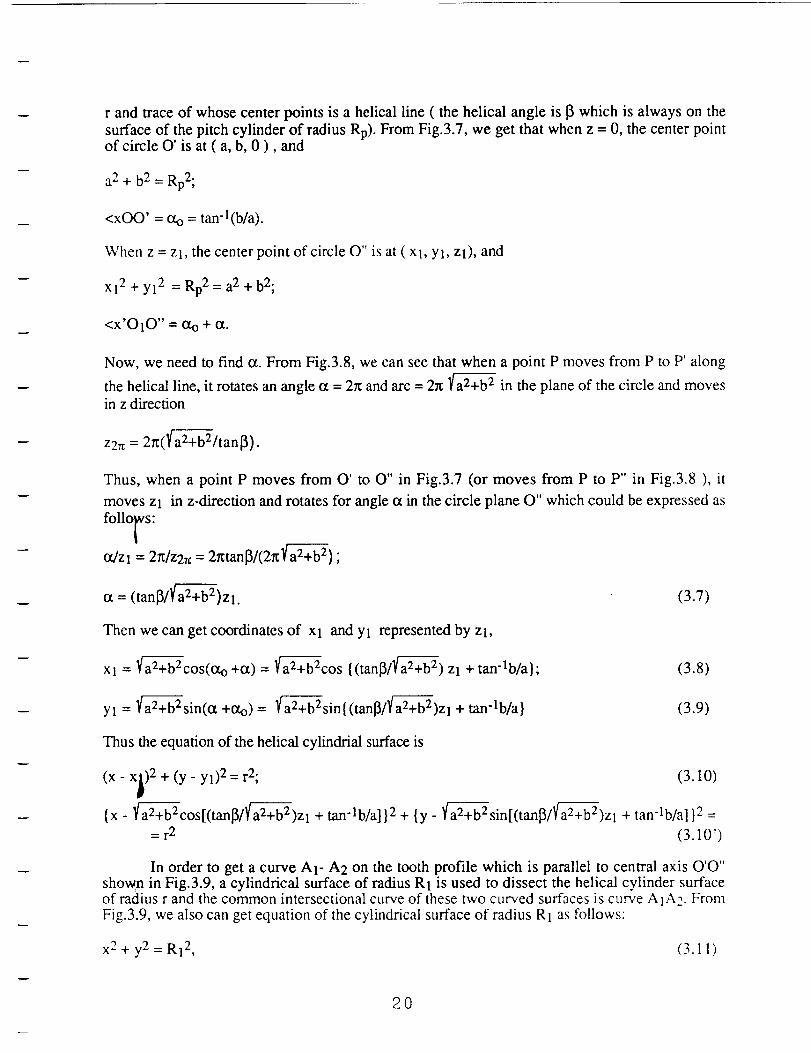
3.3.1 Formulas for Calculating Curved Surfaces of Conformal (Novikov) Gear
Since any transverse section of the surface of a Novikov gear is an arc and also a Novikovgear is a helical gear, the profile surface of this gear can be imaged as a part of a helical cylindrical
surface with radius r whose central axis wraps on the pitch cylindrical surface with radius Rp
along the angle 13shown in Fig.3.6. Thus, to get the equation of the curved surface we only need
to write down the equation of the helical cylindrical surface.
19
r andtraceof whosecenterpointsis a helicalline ( thehelical angleis 13which is alwayson thesurfaceof thepitchcylinderof radiusRp).FromFig.3.7,weget that whenz = 0, thecenterpointof circle O' is at ( a,b, 0 ), and
a2+ b2= Rp2;
<xOO' = _ = tan-l(b/a).
Whenz = Zl, thecenterpoint of circleO" isat( Xl, Yl, zl), and
Xl2+yl 2 =Rp2=a 2+b2;
<x'O10" = Oto+ or.
Now, we need to find o_. From Fig.3.8, we can see that when a point P moves from P to P' along
the helical line, it rotates an angle ot = 2_ and arc = 2_ _ in the plane of the circle and movesin z direction
z2= = 2rt(_/tanl3).
Thus, when a point P moves from O' to O" in Fig.3.7 (or moves from P to P" in Fig.3.8 ), it
moves Zl in z-direction and rotates for angle oc in the circle plane O" which could be expressed as
follows:
ot/zl = 2_/z27c = 2_tan_/(2_ a2f_+b2) ;
a = (tanl3/_)Zl. (3.7)
Then we can get coordinates of Xl and Yl represented by Zl,
Xl = _cos(oto +or) = _cos {(tanl3/a2f_+b 2) Zl + tan-lb/a}; (3.8)
Yl = a2_-_b2+b2sin(o_+Oto) = af_+b2sin{(tan]3/a2_+b2)zl + tan'lb/a} (3.9)
Thus the equation of the helical cylindrial surface is
(x- x_) 2 + (y- yl) 2=r2; (3.10)V
{x- a2fa-_+-b-2+b2cos[(tanl3/a2_+--_+b2)zl+ tan-lb/a] }2 + {y_ a2fa-2+--b-2+b2sin[(tan_/_)Zl + tan-lb/a] }2 =
= r2 (3.10')
In order to get a curve AI- A2 on the tooth profile which is parallel to central axis O'O"shoran in Fig.3.9, a cylindrical surface of radius R1 is used to dissect the helical cylinder surfaceof radius r and the common intersectional curve of these two curved surfaces is curve A1A2. From
Fig.3.9, we also can get equation of the cylindrical surface of radius R1 as follows:
x 2 + y2 = R12, (3.11)
20
x2+ y2 -- R12, (3.11)
where
R12 = (a - rsin0) 2 + (b - rcos0) 2. (3.12)
Therefore, when a series of values z = Zl is given, coordinates (x, y) of the points on the curveA1A2 can be calculated from the equations (3.10') and (3.12).
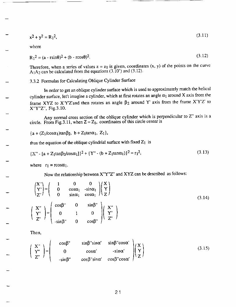
3.3.2 Formulas for Calculating Oblique Cylinder Surface
In order to get an oblique cylinder surface which is used to approximately match the helical
cylinder surface, let't imagine a cylinder, which at first rotates an angle o_1 around X axis from the
frame XYZ to X'Y'Z'and then rotates an angle [_2 around Y' axis from the frame X'Y'Z' to
X"Y"Z", Fig.3.10.
Any normal cross section of the oblique cylinder which is perpendicular to Z" axis is acircle. From Fig.3.11, when Z = Z1, coordinates of this circle center is
{a + (Z1/cosotl)tan[32, b + Zltanotl, Z1},
thus the equation of the oblique cylindrial surface with fixed ZI is
{X" - [a + Zltan_9./cosotl] }2 + {Y"- (b + Zltanoq)} 2 = rl 2, (3.13)
where rl = rcosO_l.
Now the relationship between X"Y"Z" and XYZ can be described as follows:
(x)(y' =
Z'
x,,)t!
Z"
1 0 0)(x)0 cosczl -simzl
0 sinotl COS0t 1
os000,si.)(,)0,-sinl3" 0 cosl3" Z"
(3.14)
Then,
x,,)t_
Z" coslY'0 sinlY'sinOt'cosoC sinlY'c°s°C )( X)-sinot' Y-sinl3" cosl3"sinot' cos_"cos(z' Z
(3.15)
21
X"= Xcos[3" + Ysinl3"sino_' + Zsin[3"cosot' (3.16)
Y" =Ycoso_' - Zsin_' (3.17)
Substituting (3.16), (3.17) into (3.13), an equation of oblique cylindrical surface becomes
{XcoslY' + Ysinot'sin[3" + ZlCOSOt'sin[3" - [a + (tan[Y'/coso_')Z1] }2 +
{Ycos0_' - Zlsincx' - (b + Zltamx') }2 = rl 2. (3.18)
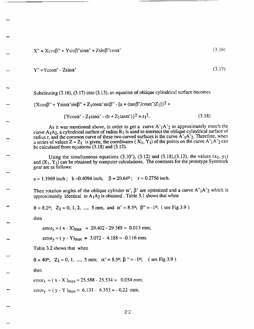
As it was mentioned above, in order to get a curve A'IA'2 to approximately match the
curve A1A2, a cylindrical surface of radius R1 is used to intersect the oblique cylindrical surface ofradius r, and the common curve of these two curved surfaces is the curve A' 1A'2. Therefore, whena series of values Z = Z1 is given, the coordinates ( X1, Y1) of the points on the curve A'IA'2 can
be calculated from equations (3.18) and (3.12).
Using the simultaneous equations (3.10'), (3.12) and (3.18),(3.12), the values (Xl, Yl)and (X1, Y1) can be obtained by computer calculations. The constants for the prototype Symmark
gear are as follows:
a = 1.1969 inch ; b --0.4094 inch; 13= 20.64° ; r = 0.2756 inch.
Then rotation angles of the oblique cylinder o_', 13' are optimized and a curve A' 1A'2 which is
approximately identical to A1A2 is obtained. Table 3.1 shows that when
0 = 8.2°; Zl = 0, 1, 2, ..., 5 mm, and o_' = 8.5°; [3" = -1o; ( see Fig.3.9 )
then
errorx = ( x - X)max = 29.402 - 29 389 = 0.013 mm;
errory = ( y - Y)max = 3.072 - 4.188 = -0.116 ram.
Table 3.2 shows that when
0=40°; ZI=0,1 ..... 5mm; o_'=8.5o;[3"=-1o; (seeFig.3.9)
then
errorx = ( x - X )max = 25.588 - 25.534 = 0.054 mm;
errory = ( y - Y )max = 6.131 - 6.353 = - 0.22 mm.
22
Thus, thepiecesof laminatescut obliquely from a laminatetubecanapproximatelymatchtheprofileof theprototypeSymmarkgearandtheerrorcanbecompensatedby thelocalcomplianceofthelaminates.
3.4 DESIGNOFSPECIALLAMINATE PIECES
The abovecalculationshaveshownthat the contactstresson the laminateis less then10,000psi andits sheardeformationis 0.025in under1250lb-in torque.ThestatictestresultsinTables2.1,2.2,2.3alsoindicatethattheultimatecompressionstressesof the laminatesarehigherthan20,000psi. According to the above described calculations, the test results, and also to themeasured amount of clearance between the gear teeth, as well as in order to reduce fabricationdifficulties, parameters of the laminates were specified as follows:
rubber material - natural rubber,
thickness of one rubber layer - 0.015 in;
number of rubber layers - 3-4;
total thickness of rubber - 0.045-0.060 in (shear strain 56%-42%);
thickness of one intermediate steel layer - 0.002 in.
Geometric dimensions of the test gear are such that the length of arc of the profile is 0.15-0.20 in.,thus the required width of the laminate is about 0.15-0.20 in. To obtain an adequqte flexibility ofthe laminate piece to match the tooth profile there was established a relationship between thethickness of the top steel layer and the length of the laminate. For a top steel layer thickness lessthan 0.004 inch, longer flat laminates (length about 0.5 inch) were chosen since they had adequateflexibility to match the tooth profile; for the top steel layer thickness 0.01-0.02 inch, the laminate
pieces 0.15-0.2 inch long were cut from the laminate tube in order to match the tooth profile.
3.5 TEST ARRANGEMENT AND RESULTS
The test process had two stages:
1) rotation test (rotational speed 200 rev/min) and
2) vibration fatigue test
3.5.1 Rotation Tests
For these tests, all laminates were made in our lab with 0.015 inch thickness of rubber
layers and 0.002 inch thickness of intermediate steel plates. The torque capacity tests wereperformed for different structure and thickness of the top steel layer; various numbers of rubberlayers; various width of laminates; various positions of laminate attachment on the tooth profile.The test results are shown in Table 3.3.
At first, the laminates had four layers of rubber, the thickness of rubber sheet was 0.015inch with area 0.45*0.2 sq.inch and the top steel thickness 0.002"8=0.016 inch; the top steellayer was made thicker to avoid indentation of the laminate under high contact stresses. The appliedtorque was 50, 100, 150, 200 lb-in. After rotating for 1,300 cycles the top steel layer was failingdue to bending. The cause of failure was the fact that the laminate pieces were too wide, thus thebottom side of the laminates already exceeded the circular curved area of the working segment ofthe tooth profile. During the meshing process, the shear deformation of the laminate caused the
23
m
bottom of the laminate to touch fillet of the tooth, and then the top steel layer was broken due to itslow flexibility.
In the next step, the laminate width was changed from 0.2 to 0.14 inch and applied torqueswere increased to 200, 250, 300, 350, 400 lb-in, while the total number of rotation cycles wasincreased to 4,000. The laminates were failing due to bending of the top steel layer and, also,some layers of steel and rubber were unglued; a fast bonding cyanoacrilate metal-to-rubber gluewas used. Since the thicker top steel layer did not have adequate flexibility, the thinner top steellayer with thickness 0,002*3--0.006 inch and area 0.5*0.2 sq.inch was chosen for the next seriesof tests. As #3 of Table 3.3 shows, the maximum applied torque reached 500 lb-in and the totalnumber of rotation cycles reached 5,500 ( for 0-500 lb-in torque ). After the width of laminate wasfurther reduced to 0.16 inch, the maximum applied torque was increased to 700 lb-in (for 1,200rotation cycles), with the total number of rotation cycles 5,600 as indicated in #4 of Table 3.3.After correcting position deviations of the laminates on the tooth profile to values smaller than0.02in, further improvements were achieved (the maximum torque 850 lb-in for 300 rotatingcycles, with the total number of rotating cycles 6,500). All laminates were failing by bending orbreakage of the steel layer, as well as by some rubber spread.
3.5.2 Vibratory Tests
In order to improve efficiency of the experimental studies during the initial development stage,vibratory fatigue tests were introduced instead of the rotation tests. In the rotation tests, a lot oftime was spent to prepare the prototype gear for which fabrication and attachment of 6"12=72pieces of laminate by hand was required. To keep the same load conditions for the vibratory test asfor the rotation test (shear deformation of the laminates during the meshing process should be same
as for therotation tests), the required alternate rotation angle was established to be about 5°:
the prototype gear has 12 teeth; since six pieces of laminate were applied to each tooth, then
each laminate piece rotates in one rotating cycle for 360°/12"6 = 5 o.
The alternating rotation angle measurement system is shown in Fig.3.12. It transfers arotational motion to a translational motion which is then measured by LVDT. One end of a thickwire is wound onto a coupling mounted on the gear shaft and another end is connected to a spring.When the gear shaft rotates, a block fixed on the wire moves up-and-down and pushes a LVDT.Then through a LVDT conditioner, the displacement signals of the LVDT can be displayed (orstored) on Nicolet 4094 oscilloscope. Finally, a rotation angle is calculated by converting themeasured displacement of the LVDT. Vibration frequency was selected to be 1 Hz. The totaldynamic torque includes 30-40 % static preload plus 60-70% alternating torque. The values of thestatic and alternating torque components were displayed on the front panel (controller) of the testmachine.
The prototype gear (Symmark gear having symmetrical arcs) with laminates attached eitherto the addendum or to the dedendum part of the tooth profile were tested. Table 3.4 includes 8 setsof the test result. It shows that there are two sets of the test results. Regardless of where thelaminates were attached - on addendum or on dedendum part - the maximum dynamic torquereached 1000 lb-in with more than 1000 cycles, and the laminates were always failing byseparation of the top steel layer. In other sets of tests having lower maximum torques (700-800 Ib-in), the failures were due to ungluing or tearing off of the rubber layers.
From analysis of these test results, it was suggested that the main failure reason was theinadequate adhesive strength of the glue. In the next step, the prototype gear with the laminates cutfrom the laminate tubes fabricated by CR Industries Co. (using high temperature bonding) weretested. The test results are shown in Table 3.5. In one set of tests the maximum torque reached
24
1250 lb-ia, while in other tests it was in the range of 700-800 lb-in. All laminates had failed byrubber failure, not due to bonding disintegration. It means that the adhesive strength in this case
was higher than strength of the rubber itself.
According to the strength calculations of the prototype gear, the average contact stress islower than 10,000 psi and thus is much lower than the maximun allowable compression stress
20,000 psi for the laminates as described in Chapter 2. Therefore, it was concluded, that thereason for failure of the laminates on the tooth profile is not the strength of the laminate itself. It is
possible that the effective shape of the tooth profiles deteriorated after the laminates were attachedto them.
3.6 IMPROVING THE LAMINATE-COATED TOOTH PROFILE
It was already known that in the direction of the tooth width the laminate cut from anoblique cylinder can match the helical cylindrical tooth prof'de if the length of the laminate is about0.2 inch. After the unsuccessful series of tests, a study was performed to find out if the toothprofile of the laminate-coated gear matches the tooth profile of the counterpart Symmark gear in thedirection of transverse cross section.
A transparent frame shown in Fig.3.13 was made in order to observe the meshing processof the laminate coated gear. We found that two tooth profiles did not touch conformally along acircular surface, but only touched at the edge of the laminate. Then a computer graphical simulationshown in Fig.3.14 was performed. Obviously, the uniform thickness laminate shown withdashed line could not fit the tooth profile shown with solid line. A maximum error is about 0.035inch. This is why the thinner top steel layer (thickness 0.006 in.) could withstand 800 lb-in torque(see Table 3.3, No.5) during the rotating test. It happened because it is flexible enough to matchthe engaging tooth profile. However, its bending strength was not high enough for such highcontact stresses. It seems that the laminates made by CR Industries Co. failed in a rubber tearingmode because the deteriorated tooth profile distorted the rubber of the laminate during the meshing
process.
In accordance with this analysis, the laminate pieces cut from the tube made by CRIndustries Co., were grounded along the arc in order to reach the thickness profile corresponding
to the shape obtained from the computer graghics simulation. This led to a significantimprovement in performance. Several test results have shown the following: the maximum torqueincreased to 1,300 lb-in lasting 650 vibration cycles with the total number of cycles 1,300 for the
applied torques 700 to 1300 lb-in; the number of the rotation cycles was more than 1,000 with 8°
and 1 Hz frequency under 1,000 lb-in, torque;, the number of rotation cycles is 1800 with 6degree and 1 Hz Under 800 lb-in torque. All laminates were failing in such a mode that the topsteel layer gradually shifted down and the rubber was gradually spreading, but no pronouncedrubber failure was observed. In addition, rotation cycles reached 10,000-12,000 (half hour) with
rotation angle 1o and 8-10 Hz under 800-1,000 lb-in torque. In such a regime the laminates haveshown only a minor spreading. These results are shown in Table 3.6 from which it can be seenthat the laminates could be subjected to 1600 lb-in static torque. The ensuing stress
s = 1600/(1.25"0.12)= 10,700 psi
is corresponding with the properties of laminates as described in Chapter 2.2. But when the gear dynamictest ( under load and rotation) was performed, the laminates failed in a rubber spreading mode. This led toa study of dynamic properties of laminates as described in Chapter 2.3.
25
CHAPTER4 COMPOSITEGEAR
4.1 MESHING CONDITIONS OF COMI_SITE GEAR SYSTEM AND GENERATION OFTEETH PROFILES
See Appendix 1 "Study of Meshing Condition of A Novel Gear System"
4.2 DESIGN OF THE COMPOSITE GEAR
According to the concepts of the composite gear system described in Chapter 1 and in the
Appendix, a pair of gears was designed which included an involute gear meshing with a compositegear. The set was fabricated for testing on the Schenck-Pegasus servohydraulic torsional testsystem (see Fig.3.2) using gear pump cases as gear housings. Design dimensions of the gearsshould allow them to be fitted in these housings.
4.2.1 Design Parameters of Prototype Composite Gears
Considering the given center distance of the gear pump case 2.52 inch and for easyfabrication (minimun tooth number), basic parameters of prototype gears are as follows: teeth
numbers of both the involute the composite gears N1 = N2 =10, diametral pitch Pd = 4, facewidth B = 1.25 inch. Others parameters are:
a) Pressure Angle o_
The formula which considers the minimum teeth number without undercut for an involute
gear is
Nmin = 2h*a/(sin0Q 2 = 2*l/(sin31°) 2 = 8 < 10, (4.1)
where h*a = 1 is addendum factor. Thus pressure angle 0t = 31 ° satisfies the requirment of
minimum tooth number for the involute gear.
b) Operating pressure angle 0_'
The given center distance of the housing is C'=2.52 inch and the center distance for theprototype gears is C=2.5 inch,
c = (N1 + N2)/2Pd = (10 + 10)/2"4 = 2.5.
Thus •
a' = cos-1 [(C/C')cosot] = cos-l[(2.5/2.52)cos31 o] = 31.7371 o.
c) Check of Contact Ratio E
E = 1/2X{Nl(tantXal - tantx') + N2(tanCta2 - tantx')},
where:
Oral, C_a2are addendum angles of gear 1 and gear 2;
26
Oral = OCa2= cos'l(rbl/ral) = cos-1(1.07146/1.5) = 44.4136 °'
where:
pitch radius rpl = N1/2Pd = 10/2"4 = 1.25 in;
base radius rbl = rplCOSO_ = 1.25cos31 ° = 1.07146 in;
addendum radius ral = rpl + 1/Pd = 1.25 + 0.25 = 1.5;
E = 1/r_{ 10(tan44.4136 ° - tan31.7371°)} = 1.15.
4.2.2 Structural Design of the Prototype Composite Gear
The basic design concept of composite gears involves only pure rolling motion between the
contacting tooth profiles, and torsional deformations of laminate bushings replace the sliding motionbetween the tooth profiles during the meshing process. A pair includes a composite gear and a involutegear. The structural design of the prototype composite gear is shown in Fig.4.1. Each tooth of thecomposite gear consists of a tooth segment 1, a pair of laminate bushings 2 and pins 3 inside the bushingswhich connect them with the tooth segments. The laminate bushings 2 have two functions. They serve asbearings and also as torsional springs with high radial stiffness. Each tooth segment is mounted on twopins whose other ends are press fit into the laminate bushings. The outside sleeves of the laminatebushings are fixed in the gear face plates 4. During a meshing process, there is a pure rolling motionbetween the surfaces of the tooth segment of the composite gear and the tooth profile of the involute gear,
meanwhile the tooth segment rotates about 10o. The rotation is supported by torsional deformation of thelaminate bushings (i.e. by shear deformation of the rubber).
4.2.3 Strength Calculations
a) Bending Stresses [20]
Bending of an involute gear tooth is equivalent to bending of a cantilever beam. However,it is not necessary to check the bending stresses for the composite gear since its tooth segment canrotate around the bushing pins and thus is experiencing pure compression, see Fig. 1.4 in Ch. 1.Thus, the bending stress is checked only for the involute gear [20],
St = (Wt*ka/kv)Pd/B(ks*km/J) psi. (4.2)
Here: St is bending stress, psi; Wt --- transmitted tangential load, lb;factor = 1.15; ks --- size factor =1; km --- load distribution factor = 1.4;
factor = 0.8; J --- geometry factor = 0.30.
ka --- applicationkv --- dynamic
St < Sat*kL/kTkR, (4.3)
where: Sat --- allowable bending strength =36,000 psi ( steel HB =250 );=1; kT --- temperature factor = 1; kR --- reliability factor = 1.25.
k L --- life factor
Thus,
St = 36,000"1/1#. 1.25 = 28,000 psi,
and
27
Wt = (Stkv/ka)B/Pd(J/kskm) = (28,800"0.8/1.15) 1.25/4(0.30/1" 1.4) = 1,300 lb.
Therefore ( see Fig.4.2 ) the resultant (compression) tooth load is:
W = WJcoso_ = 1,300/cos31 ° = 1,500 lb.
Radial tooth load is:
Wd = Wttan_ = 1,300tan31 o = 780 lb,
and the torque is
T = Wtrp = 1,300" 1.25 = 1,625 lb-in
b) Contact Stress of Composite Gears [20]
The contact stress Sc is
Sc = Cp(WtCaCsCmCf/CvdFI) 1/2, (4.4)
and the transmitted tangential load Wt is
Wt = Sc2CvdFI/Cp2CaCsCmCf. (4.5)
Value of Sc in equation (4.5) is
Sc < Sat(CLCH/CTCR), (4.6)
where: Sac --- allowable contract stress=122 ksi for HB = 277 or RC = 28 (tooth hardness of the
test involute gear); CL --- life factor =1 for N=107; CH --- hardness ratio factor = 1.09 for
surface finish = 32 pin; CT --- temperature factor = 1; CR --- reliability factor = 1.25. Thus
Sc < 122"1"1.09/1"1.25 = 106,400 psi.
Other parameters in equation (4.4) are: Wt --- transmitted tangential load; Cp--- elasticcoefficient = 2,300 for steel; Ca--- application factor = 1.15; Cs--- size factor = 1.0;CI --- load distribution factor=- 1.6; Cf--- surface condition factor = 1; Cv --- dynamic factor =
0.8 for Vt = 1300 ft/min; d --- pitch diameter = 2.5 in; F --- face width of the gears = 1.25in; I --- geometry factor = 0.092. Thus,.
Wt = Sc20.8"2.5 * 1.25*0.1104/2,3002* 1.15" 1* 1.6* 1 = 2.36* 10-8Sc 2,
and the allowable maximun torque T is
T = Wt(d/2) = 1.25Wt = 2.95* 10-8Sc 2.
Therefore, for the prototype involute gear
T = 2.95"10 -8* 106,4002 = 3351b-in.
28
Therelatively low torquevalueis dueto thefact thattheprototypegearwasfabricatedfrom a mild(notheattreated)steel.It shouldbenotedthattheallowablecontactstressesfor thecompositegearcanbeexpectedto beabouttwo timeshigherthanthatfor the involutegear.It wasshownin [26]thatthe allowablecontactstressesfor apurerolling motionaretwo to threetimeshigherthantheallowablecontactstressesfor acombinationof rolling andsliding motions. Thustheallowablecontactstressfor the compositegearcan be assumedto beSc-comp= 2Sc, and the maximunallowabletorquefor compositegearswouldbe
Tcomp= 3.54*10-SS2c.comp= 3.54*10-8(2* 106,400)2 = 1,337lb-in.
c) The ShaftDiameterof Gearsd [20]
d = {(32/_)n[M/Se+ (q-'3-/2)(T/Su)]} 1/3, (4.7)
where(for theshaftmaterialsteel1040): n --- designfactor= 1.6;Fr(L/4) = 1,500(2.8/4)= 1,050lb-in; T --- torque= 1,625lb-in;strength= 16,000psi; Su--- ultimatestrength= 103,000psi.Thus,
M --- bendingmoment=Se--- bendingendurance
d = {(32/_)1.6[1,050/16,000+ (f'3-/2)(1,625/103,000)]}1/3= 1.09in.
d) PinDiameterof theToothSegmentdl in theCompositeGear
The pin is subjectedto a shearloadwhich is equalto half compressionload(W/2) appliedto thegear,
Xa < W/2(_d2/4), (4.8)
where Xa is allowable shear stress = 0.6Su/2 = 0.6* 103,000/2 = 30,900psi. Thus
a 1,500
2n'30,900- 0.176 in.
e) Design of Laminated Bushing for the Composite Gear
All dimensions of the bushing are determined by the following three criteria:
* The inside diameter of the bushing should be equal to the above calculated pin diameter;,
* Value of the maximum shear deformation of rubber should be smaller than the total thickness of
rubber.
* Restrictions of structural space in the housing should be considered.
The laminated bushing, Fig.4.3, consists of an outer and inner steel sleeves with thethickness 0.02 in. each, five layers of rubber made of rubber sheet 0.015 in., and four interleavelayers of steel 0.002 in. thick. The main dimensions of the bushing are: inside diameter din =0.1875 in.; outside diameter dout= 0.46 in.; width B = 0.44 in.; total thickness of rubber h =
0.075 in.(=0.015"5 in.).
The maximun shear deformation of rubber in the laminated bushing during a meshing
process is determined as follows:
29
themaximunrotationangleof thetooth segment 12° = 0.21rad;
the smallest radius of a rubber layer rl = 0.5"(0.1875+0.02"2)= O. 114 in.;
the largest radius of a rubber layer r2 = 0.5"(0.46-0.02"2)= 0.21 in.
Accordingly, the length of rotation arc is 11= riot = 0.114"0.21 = 0.024 in.
12 = r2ot = 0.21"0.21 = 0.044 in.;
the shear strain E1 = ll/h = 0.024/0.075 = 32 %;
_2 = 12/h = 0.044/0.075 = 59 %.
Therefore, the shear deformation of the laminate bushing is in the allowable range.
Compression loading of the laminate bushing is
Ocom = Fcom/A = 1500 1b/0.369 sq.in = 4,058 psi,
where Fcom is compresion force; A - projection of the rubber layer surface area of the bushing,
A = 2r2B = 2*0.42*0.44 = 0.369 sq.in;
factor 2 considers two bushing supporting one tooth segment.
According to the previous test results in Chapter 2, the above compression stress satisfiesthe strength requirements of the laminate.
4.3 APPROXIMATION OF EXTERNAL SURFACE OF THE TOOTH SEGMENT BYCIRCULAR ARCS
It can be seen from Table 4.1, that variation of the curvature radius of the profile surface
with the center O' is ( 0.6971 - 0.6753 ) / 0.6753 = 3.2%. Therefore, it can be concluded that if
an optimum center Op were chosen, the radius variation would become minimal and a circularprofile of the segment would approximate the computed profile, and manufacturing of the toothsegment would be simplified. A method of three point approximation on the arc was used forfinding the optimum center O o. After the optimization procedure had been performed, it was foundthat the best three points are p'oints of addendum (Xl, Yl), pitch circle (x2, Y2) and dedendum (x3,
Y3) which were used to form the circular surface. The calculation from a set of simultaneousequations is as follows:
(Xl - x) 2 + (Yl - y)2 = (x2- x) 2 + (Y2- y)2
(Xl - x) 2 + (Yl - y)2 = (x3- x) 2 + (Y3 - y)2
(4.9)
Simplifying these equations, obtain
(x2 - Xl)X + (Y2 - Yl)Y = [(x2 2- Xl 2) + (Y22 - y12)]/2
(x3 - Xl)X + (Y3- Yl)Y = [(x3 2 " Xl 2) + (Y32 - y12)]/2
(4.9')
3O
By solving these simultaneousequations, the optimum center is found to be Op(0.10594,0.036165).The differencebetweenaccuratecurvatureradiiandtheconstantradiusassociatedwiththe optimum center is 0.5850 - 0.5829 = 0.021 in, or the relative deviation (0.5850-0.5829)/0.5829= 0.36%.Sincetheerror is very smallandcanbeeasily compensatedby localcomplianceof the laminatedbushing,thecircularsurfaceof thetoothsegmentwasadoptedin thedesignasshownin Fig.4.4.
4.4 TESTINGOFLAMINATED BUSHINGS
The laminatedbushingis an important componentof thecompositegear. According toprevious testresults,the designparameters,suchascompressionstressand stiffnessaswell asshearstiffness, could satisfy the strengthrequerement.However, to considerthe differencesbetweenlaminatedplateandlaminatedbushing,the testswereperformedin thefollowing threeaspects.
4.4.1 Torsionalstiffnessof LaminatedBushing
As mentionedabove,theshearstiffnessof laminatesplateis very small. The laminatedbushingsmadein our lab havea spiralstructure,e.g.arubberstrip andasteelstripwerebondedand wound around the steel sleeve. In order to obtain a low shearstiffness,eachlaminatedbushingwasslit thus generatinga narrowgap. Two designsof the laminatedbushings:with agapandwithout thegapweretestedfor their shearstiffness,compressionstiffnessandfatiguelife.The testresultsindicatethattherearenosignificantdifferencesfor thesetwo structures.Thusthelaminatedbushingswithoutthegapwereusedin thecompositegear.Thetorsionalstiffnessof thelaminatedbushingis very small,about0.08-0.1lb-in/°, asshownin Fig.4.5
4.4.2 CompressionStressandCompressionModulus
Thetestswereperformedon INSTRONtestmashine.Underthecompressionload 1,080lb the compressionstressis 5,000psi (designrequirementis 4,058 psi) with thecompressionstrain 21% and compressionmodulus is 47,600psi as shownin Table 4.2. The testswererepeatedseveraltimesandtherepeatibilityof theresultswasgood.
4.4.3FatigueLife
The fatigue testsof the laminatedbushingssimulatedtheir real load condition in themeshingprocessof compositegears,e.g.therelativerotationangleof insideandoutsiderings ofthe laminatebushingwas 150 with acompressionpreload( compressionstrain20%). The testsetup is shownin Fig.4.6. After 12hourstestwith thetotalnumberof loadingcycles4"105(5.5hourswith loadingfrequency5Hz and4 hourswith frequency18Hz), the laminatedbushingwas intact. Fig.4.7 indicatesthatthetorsionalstiffnessof the laminatedbushinghasnotchangedafter thefatiguetests.Thetemperatuteriseof thelaminatedbushingduringthetestswas5-7OFasshownin Fig.4.8
4.5TESTSOFCOMPOSITEGEARS
Tooth segmentswere fabricatedby wire EDM and thenmeasuredusing a CoordinateMeasuringMachineat theGM TechnicalCenter.Schematicof thetooth segmentindicating themeasureddimensions is shown in Fig. 4.9; the final drawing dimensions and measureddimensionsfor two segmentsarelisted in Table4.3. Althoughtherewerediscoveredsignific_mtdeviations,adecisionhadbeenmadeto goaheadwith thetestsdueto timeconstraints.
31
Rotationaltestsof thecompositegearpair wereperformedon SCHENCK-PEGASUStorsionalmachinedescribedin Chapter3. The testsstartedat low speed(200rpm)with the graduallyincreasingspeedup to 1,600rpmandrunningat torquesupto 300lb-in. Then,thetestingwasperformedin stages.
At thefirst stage,thegearshadbeenrunat300rpm & 200lb-in; 300rpm& 300lb-in; 400rpm&200lb-in; 400rpm & 300lb-in, for onehalf hourat eachregime.Temperatureincreasewasfrom 4°F atthefirst regimeto about10°Fat theheaviestregime.At thesecondstagetherunningregimeswere400rpm& 300lb-in; 500rpm& 200lb-in; 500rpm& 300lb-in, all onehalf hourlong;at thethirdstage- 6(X)rpm& 200lb-in and600rpm& 300lb-in; at thefourthstage- from700rpm& 200lb-in upto 800rpm&400lb-in (ninelapsby 1/2hour).After eachstage,minorrepairswereperformed,relatedto imperfectionsof glue lines in the bushingsandto inaccuraciesof the teethprofiles togetherwith soft surfacesof theteeth.At thefinal fifth stageof testingtherunswereperformedat 1,000rpm & 300lb-in (2.9HP); 1,000rpm & 400 lb-in (4.6HP); 1,200rpm & 300lb-in (4.1HP); and 1,200rpm & 400lb-in (7.2HP), all 1/2hourlong.Temperatureincreasesof thegearsweremeasuredto be47°F for the4.1HPregimeand81oFfor the7.2HP regime.No desintegrationof thebushingswasobserved,althoughthesurfaceof theteethsegmentsdeterioratedsignificantly.
It wasconsidereda satisfactoryfirst testsincethesegmentswerefabricatedwith largedeviationsof basicdimensionsfrom thespecifiedvaluesandwerenothardened.This wasinterpretedasanindicatorof a significantcompensatingability of therubber-metallaminatedbushingsandof low sensitivityof thesystemto manufacturingerrors.
CONCLUSIONS
1. Thin-layered rubber-metal laminates can accomodate very high static compressive forces, limited bystrength of intermediate metal layers. It was demonstrated that specific compression forces up to 80 -90,000 psi can be accomodated.
2. Dynamic compression forces are limited by strength of bonding between the rubber and metal layers.High strength bonding agents have to be used for the laminates which are employed in powertransmission components.
3. Test facilities for testing of thin-layered rubber-metal laminates as well as novel gear concepts have beendeveloped.
4. Conformal gears with laminate coating of the profiles have been tested; it was demonstrated that thegears have a potential for transmitting at least the same torque as steel gears.
5. Geometrical analysis has shown that meshing conditions of the composite gear system correspond to anapproximate conjugate engagement. Optimization has been performed allowing to achieve a very goodapproximation to the conjugate system.
6. Testing of the fin'st prototype of the compoisite gear system has demonstrated that it is a viable system.Next prototype should use hard contacting surfaces and utilize professionally bonded laminatedbearings.
REFERENCES
1. Dinsdale, J., Jones, P.F., "The Electronic Gearbox
Mechanical Couplings" CIRP Annals, 1987, pp. 247-249.- Computer Software Replaces
32
2. Winter, H., "Evolutionof GearCalculaitonMethods,"Proceed.of the2ndWorld CongressonGearing, Vol. 1, pp. 3-19,Paris,1985.
3. Dudley,D.W., "TheEvolutionof theGearArt," pp.90.
4. Koniuk, E.A., Andreev, S.V., Fiktash, M.D., "Strength Analysis for Teeth of GearsReinforced with ContinuousFibers," Mekhanika Kompositnikh Materialov (MechanicsofComposite Materials), 1982,No. 5, pp. 937-939 (In Russian)
5. Ikegami, K., Takada, M., "Strength of Fiber Reinforced Plastic Gears of MonocoqueStructures", ASME Paper84-DET-72, ASME, 1984.
6. Prince,M., "LargeSpacecraftActive DeploymentHinges,"AIAA Paper83-0909-CP,AIAA,1983.
7. Weck, M. Konig, W., (eds) "ZahnradungGetribeuntersuchungen[Studies of GearsandTransmissions]",Proceedingsof the 24th Workshop,WZL - Techn,University of Aachen,1983 (in German).
8. Dudley,D.W., "Handbookof PracticalGearDesign",pp.667.
9. Litvin, F.L., Zhang, J., Chaing, W.-S., Coy, J. J., Handschuh, R.F., "Crowned Spur
Gears: Optimal Geometry and Generation", AGMA Technical Paper 87FTM7, AGMA ,1987.
10. Wildhaber, E., "Helical Gearing," U.S. patent 1,601,750.
11. Smith, J.D., "Gears and Their Vibration," Marcel Decker, 1983, 170 pp.
12. Berestnev, O.V., "Self-Aligning Gears," Nauka i Technika Publishing House, Minsk, 1983,
312 pp (in Russian).
13. Anderson, N.E., Lowenthal, S.M., "Spur - Gear - System Efficiency at Part and Full
Load," NASA Technical Paper 1622, 1980.
14. Rivin, E.I.," Gears Having Resilient Coatings", US Patent4,184,380.
15. Rivin, E.I., "Mechanical Design of Robots," McGraw-Hill, N.Y., 1988, 320 pp
16. Rivin, E.I., "Properties and Prospective Applications of Ultra-Thin-Layered Rubber-MetalLaminates for Limited Travel Bearings," Tribology International, 1983, Vol. 16, No.l, pp. 17-
26
17. Harris C., Crede, C. (Eds), "Shock and Vibration Handbook," McGraw-Hill, N.Y., i976
18. Schmidt, W.E., "Design, Testing and Performance of Elastometric Bearings," Lord
Corporation, Publication LL2129.
19. Rivin, E.I., "Design and Application Criteria for Connecting Couplings," ASME J. ofMechanisms, Transmissions, and Automation in Design, 1986, Vol. 108, pp. 96-105.
20. Joseph E. Shigley, Charlers R. Mischke, "Standard Handbook of Machine Desigh", McGraw-Hill Book Company, 1986, 1,932pp
33
21. Ishibashi,A., Yoshino,H., Hirai, H., "Design,Manufacture,and Load Carrying Capacityof Novikov Gearswith 3-5 Pinion Teethfor High GearRatios," Bulletin of JSME, 1985,Vol. 28, No. 238, pp. 701-706.
22. Chironis,N., "Designof Novikov Gears,"in GearDesignandApplication, McGraw-Hill,1967.
23. Rivin, E.I., Wu, R.-N., "A Novel Conceptof Power TransmissionGear Design," SAETechnicalPaper871646,SAE, 1987.
24.Rivin, E. I., "ConjugateGearSystem",US Patent4,944,196.
25.Dong, B., "Study of MeshingConditionof aNovel GearSystem",AGMA TechnicalPaper89FTMS1, AGMA, 1989.
26. Denning, R.E., Rice, S.L., "Surface Fatigue Researchwith the Geared Roller TestMachine", SAE Automotive EngineeringCongress,January14-16,1963
27. Biderman, V.L., Martyanova, G.V., "Stressed Condition of Metal Armature duringCompression of Thin-LayeredRubber-MetalElasticElements", in Raschetyna prochnost[Strength Computations],# 26, Mashinostroenie,Moscow, 1985,pp.52-56(in Russian)
28. P.K.FreakleyandA.R.Payne," TheoryandPracticeof Engineeringwith Rubber",AppliedSciencePublishersLTD, London, 1978.
29.Reed,T.F. " HeatBuildup of DynamicallyLoadedEngineeredElastomericComponents-1",Elastomerics, Nov.1989.
30. Allan, T., " SomeAspectsof theDesignandPerformanceof Wildhaber-NovikovGearing",Instn .Mech.Engrs,Vol. 179, Pt .1, No. 30, 1964-65.
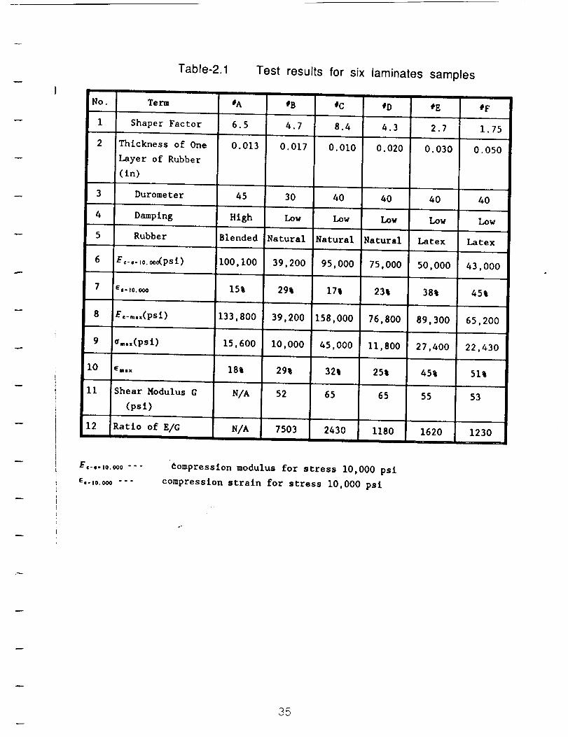
Table-2 1 Test results for six laminates samples
No.
1
2
Term
Shaper Factor
Thickness of One
Layer of Rubber
(in)
3 Durometer
4 Damp Ing
5 Rubber
6 E_- o. ,o. ooo(psi)
7 6o. io,ooo
8 £,_..,(psl)
9 ,...(psi)
I0 _..x
ii Shear Modulus G
(psi)
12 Ratio of E/G
#A #B fC _D #E #F
6.5 4.7 8.4 4.3 2.7 1.75
0.013 0.017 0.010 0.020 0.030 0.050
45 30 40 40 40 40
High Low Low Low Low Low
Blended Natural Natural Natural Latex Latex
I00,i00 39,200 95,000 75,000 50,000 43,000
15% 29% 17% 23% 38% 45%
133,800 39,200 158,000 76,800 89,300 65,200
15,600 i0,000 45,000 II,800 27,400 22,430
18% 29% 32% 25% 45% 51%
N/A 52 65 65 55 53
N/A 7503 2430 1180 1620 1230
Compression modulus for stress i0,000 psl
compression straln for stress i0,000 psi
35
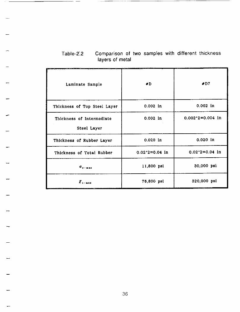
Table-2".2
Laminate Sample
Comparison of two samples with different thickness
layers of metal
Thickness of Top Steel Layer
Thickness of Intermediate
Steel Layer
Thickness of Rubber Layer
Thickness of Total Rubber
_' jr. i llsr
E¢ -mix
I
#D
0.002 in
0.002 in
0.020 in
0.02"2=0.04 in
I1,800 psi
76,800 psi
#D7
0.002 in
0.002"2=0.004 in
0.020 In
0.02"2=0.04 In
30,000 psi
320,000 psi
36
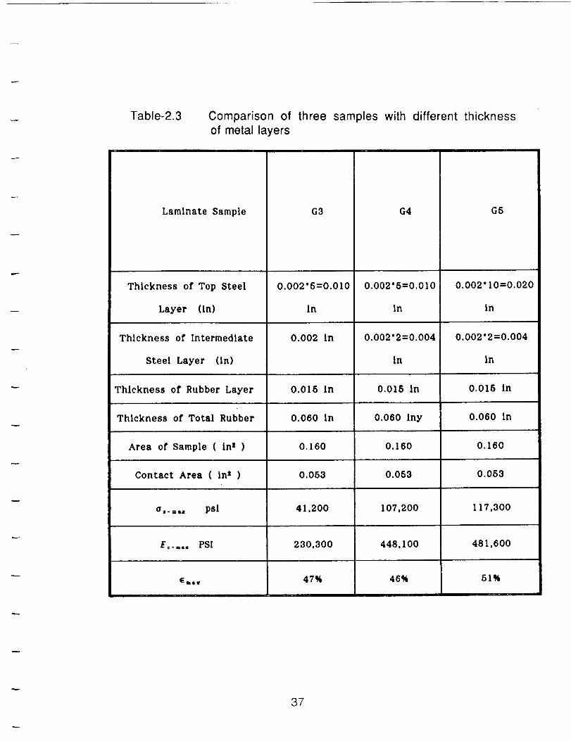
Table-2.3 Comparison of three samples with different thickness
of metal layers
G3Laminate Sample
Thickness of Top Steel
Layer (in)
Thlckness of Intermediate
Steel Layer (in)
0.002"5=0.010
in
0.002 in
Thickness of Rubber Layer 0.015 in
Thickness of Total Rubber 0.060 in
Area of Sample ( inz ) 0.160
Contact Area ( in2 ) 0.053
_,__,, psi 41,200
E ..... PSI 230.300
47%
G4
0.002"5=0.010
in
0.002"2=0.004
in
G5
0.002" I0=0.020
in
0.002"2=0.004
in
0.015 in 0.015 in
0.060 Iny 0.060 in
0.160 0.160
0.053 0.053
107,200 117,300
448,100 481,600
51%46%
37
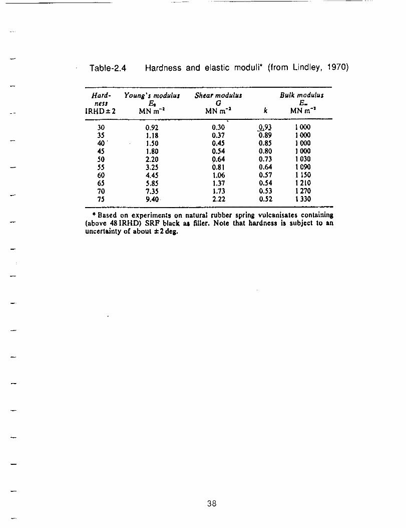
Table-2.4 Hardness and elastic moduli* (from Lindley, 1970)
Hard- Young's modulus Shear modulus Bulk modulushess Eo (7 E.
IRHD:t: 2 MN m"a MN m -a k MN m "3
30 0.92 0.30 0..,..,93 1 00035 1.18 0.37 0.89 1 00040' i.50 0.45 0.85 ! 00045 i .80 0.54 0.80 I 00050 2.20 0.64 0.73 I 03055 3.25 0.81 0.64 1 09060 4.45 1.06 0.57 I 15065 5.85 1.37 0.54 I 21070 7.35 1.73 0.53 1 27075 9.40 2.22 0.52 i 330
* Based on experiments on natural rubber spring vulcanisates containing(above 48 IRHD) SRF black as filler. Note that hardness is subject to an
uncertainty of about + 2 deg.
38
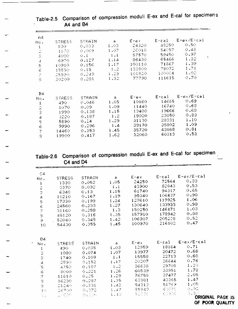
Table-2 5 Comparison of compression moduli E-ex and
A4 and B4
E-cal for specimens
A4
N,-_.
1
2
i
S
E7
5:
:-TRE:- - qTRAIN a E-e, E-cal E-e:,/E-cal
:-',3') !:i.,:_-::-', i .0:-: 24:320 4:::250 0.50
i:-:7,) ,:,.049 I .07 '.'qC_lO 54 :57 0.4:-:
40c:,(:. 0. I i .i 57570 5'345C_ 0. '37
_,':_-?_') ':'_127 i 14 P,61:-',0 ¢,_4F,E. I -'"-..,, ". . • • . . - i ,-'.¢.
i0'?i0 0.1.56 I .17 I00! !0 71::;67 i .'.::"-)
!55 SO 0. i','--', ! .2 I -',:-:',-_':>,:;! 7:'1072 i .71
2 SS '9':' .:,.2:.i9 i .T-9 !(:'!5 --''1_ i0 ':'')':>4 i .02:
.-x-_200 _'!.2',-',I 1 .:-',2 7779(') 111 E,1--q ,:3.70
B4
N,:,.
I
2
3
4
S
E
7
h
Table-2.6
:--TRE'-; -; STRAIN a E-e:,: E-cal E-e:,:/E-cal
4'90 ,:':,._'_4E, 1 .OS I01 _,0 146,q5 C).69
IQ70 0.09 i .09 11,140 iE,740 0.6'E:iCrg,:') (').17:::: i .1S 1:34:')(') i963,E, 0. E,',E:
3220 0.1 ;3:7 1 . 2 19020 23050 0. :-;:3;
5::.',90 0.24 1 • 29 :3:11:30 2',_:',:3:31 1 . 10
9990 0.296 i .4 39170 35:-:02 i .09
14460 0. :3:5:3 1 .45 3572(7 zI:'::':E,:_::0. :B1
19900 0. ,117 1 . 62 :32060 E,0:3:1 :": 0. S:3:
Comparison of compression
C4 and D4
r:_
N,:,. STRE'S:-; 'STRAIN a
1 !3:30 0.032 1 .OS
2 :3:370 0.0'92 I .1
:3 E,:'-',40 0. I:_--: i •1S
4 I1210 C,.167 i .19
S 1733,:2, (27.199 I .24
E, 2433,0 0.2:3_:':-_ 1 . 27
7 :-',I!60 0.25:-: I .3
c: _ S 120 0. :-",16 I .:-'..S
9 52040 0. :-',4S 1 .42
I0 544 :":0 0. :355 1 .45
moduli E-ex and E-cal for specimen
E-e:,: E-cal E-e:,:fE- c al
242S0 72S64 0.3:34:3'900 :-',2:-:4:3 0.5:3
174.::7 94:'::I7 (:7.65
95340 10_,4:2'.7 0. '9(:7
127610 I i'9'923 i .03,
1:306,_10 ! :3,':39:3:_ 0.9:::
150250 146,471 i .0:?,
1S7910 17:';'942 0. :-::3:
106907 20522::; 0.52
100970 216102 0.47
D4
N,:,. :E;TRE:_--;:_ :].TRA I N a
1 490 0.07: S ! . 07:
2 10',3:0 0.074 1 . (:77
:3: 174(7 0 .I0'9 I .I
,:1 279':_ 0 .Iq-2 I .17
_q _i7 S0 0. i:-',7 I .2
6 ;-;,:'00 0 . 221 1 .26
7 II:-',10 0.25 I .29
_3: 162:-:0 0 . 2',?,7 1 • :-IS
9 2124,) 0.-',?,1 1 . 42
1") -ZE7,:,,> 0 . -:72 1 . n 7: : i :E,:'O ,, --:L: £ .4:;
E-e:,: E-cal
129 S 9 i:B164
1 :::977 20472
1553;3: 2271 ::-:
":-0207 23,644
7',E,E,:-",',:_', 2970 :",
60 S :-;9 :-;:3:9S I
7675:-: :37477
6--::3:',3'.I ,I:-::-',E,5
54 ::I_:: 517E'9
S S 949 E : 7 v S
E-e:,: iE- c a 1
0.71
0.68
(.7.6:-:0.7 E,
1 . 2:3
I .7 :._;
2.05
I .47
I .0
:'.'92
ORIGINAL PAGE iSOF POOR QUALrTY
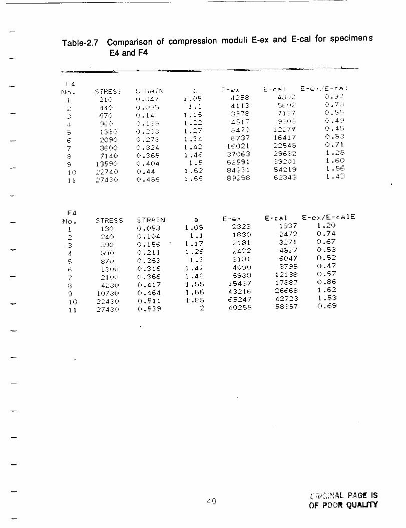
Table-2.7 Comparison of compression moduli E-ex and E-cal for specimensE4 and F4
I i
E4
r4,-,. S TREg. -" CiTRAI N a E-e:,: E-ca! E-e,/E-ca!
1 210 0.047 1 . :) S '42 S :E 4 ::-:92 0.97
440 0.0'?S I . 1 411:3: SE02 ':) . 7:-:
5 670 0.2 a 1 . l 6 :-:E_7:-: 71 ?7 O..S B
,1 '9E,3 ':3 . 1 :-_S 1 . 22 4517 9 _:,'_:- ," . '49
S 1:?,:-_,:i 0 . 2 -,::: 1 • 27 5470 122.7 "7 0. :1,S
6 2090 0. 278 I .:-:4 :37:-7 16417 0. S:-:
7 :360':2) 0. :-_',24 1 .42 16(:121 22545 0.71
:3 7140 0. :-_:ES 1 . 46 :-:706:--,' 296-_2 I . 25
9 1:35'30 C).404 1 .S 62.5'31 .-',9201 ! .G,:'_)
i0 2274,;) (') .44 1 .62 84',_--::-:i $4219 1 .SE,
11 274-10 (]).456 I .66 8929:-: 62343 1 .4:-:
F4
N I-I •
i
2
7:
4
S
6
7
9
10
ii
:'-:TRESS '.E;TRAIN a E-e:,: E-cal E-e:,:/E-c a 1E
1:-:0 0.0 57: 1 . C)S 2:::2:':: 1937 1 . 2(:1
240 0.1 (:)4 1 . 1 1 :-::30 2472 0.74
:2:9,::) C). 1 .SE, 1 . 1 7 21 81 :3271 0.67
$90 0.211 1 .26 2422 4S27 C) .S:-:
,_::7i:, 0. 263 I . 3 :31:31 6(:)47 C). 52
i :':00 0. :-:1 E, 1 . 42 4090 :-:79S 0.47
2100 0. :-:E6 1 . 46 E,_'4:-',3 12 ! :-',_'-, 0. $7
42:-:C) 0.417 1 ..SS 1543:7 178:::7 0.86
10730 0.464 I .66 4:-:216 26668 1 .62
224:-:0 0. S 11 1. ::-',S E,S247 4272:':: 1 . 57:274;'::,::, C,. S::',9 2 4C)2SS SE',:-',S7 C). 69
40OF POOR QUAL.tTY
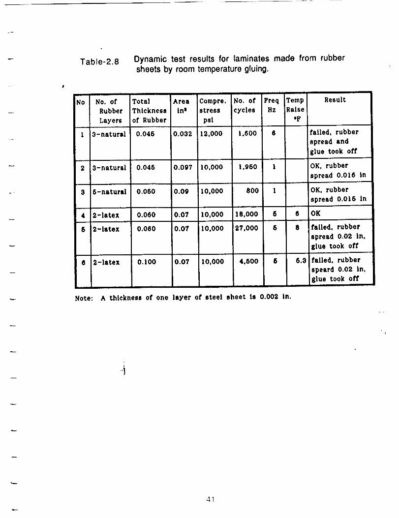
Table-2.8 Dynamic test results for laminates made from rubber
sheets by room temperature gluing.
No No. of
Rubber
Layers
Note:
Total Area Compre. No. of Freq Temp
Thickness in s stress cycles Hz Raise
of Rubber psi *F
1 3-natural 0.045 0.032 12,000 1,600 6
2 3-natural 0.046 0.097 10,000 1,960 1
8 8-natural 0.060 0.09 10,000 800 1
4 2-latex 0.060 0.07 10,000 18,000 6
5 2-latex 0.060 0.07 10,000 27,000 5
8 2-latex 0.100 0.07 lO,O00 4,500 5
A thickness of one layer of steel sheet is 0.002 in.
Result
failed, rubber
spread and
glue took off
OK, rubber
spread 0.018 In
OK, rubber
,spread 0.015 in
6 OK
8 failed, rubber
spread 0.02 in,
glue took off
5.3 failed, rubber
speard 0.02 in,
glue took off
4_
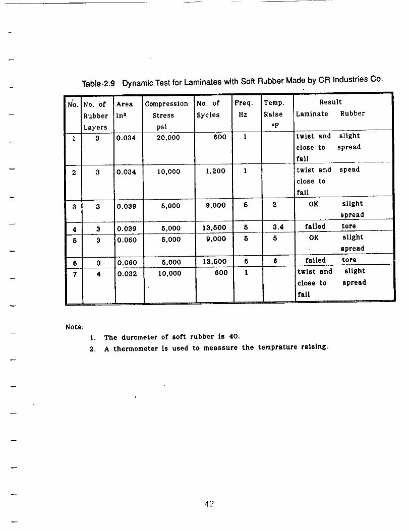
Table-2.9 Dynamic Test for Laminates with Soft Rubber Made by CR Industries Co.
N_o. No. of Area Compression No. of Freq. Temp.
Rubber in 2 Stress Sycles Hz Raise
Layers psi °F
1 3 0.034 20,000 600 1
2 3 0.034 10,000
3 3 0.039 5,000
4 3 0.039 5,000
6 3 0.060 6,000
6 3 0.060 6,000
7 4 0.032 10,000
1,200 1
9,000 6 2
13,600 5 3.4
9,000 5 5
13,500 5 6
600 I
Result
Laminate Rubber
twist and slight
close to spread
fall
twist and spead
close to
fail
OK slight
spread
failed tore
OK slight
spread
failed tore
twist and slight
close to spread
fall
Note:
I. The durometer of soft rubber is 40.
2. A thermometer Is used to meassure the temprature raising.
42
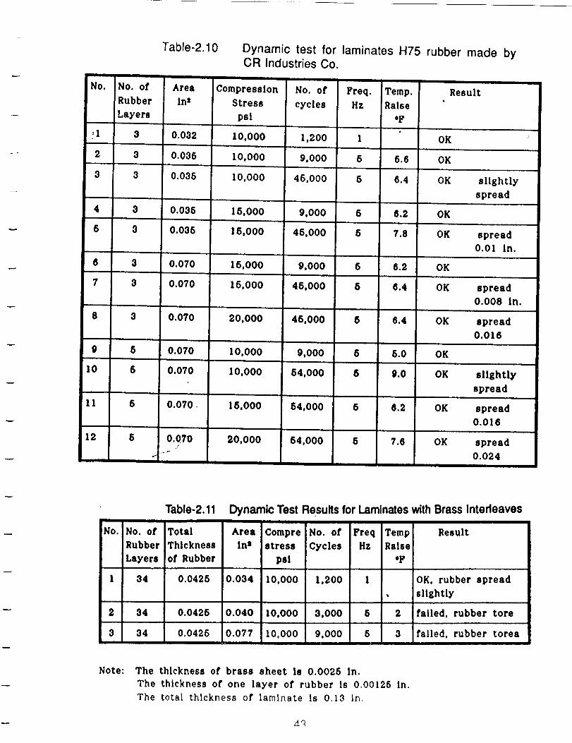
Table-2.10 Dynamic test for laminates H75 rubber made by
No. No. of Area
Rubber In2
iLayers
1 3 0.032
2 3 0.035
3 3 0.035
4 3 0.035
5 3 0.035
,,= J I
6 3 0.070
7 3 0.070
8 3 0.070
9
10
11
12
CR Industries Co.
Compression No. of Freq. Temp.
Stress cycles Hz Raise
psi "F
I0,000 1,200 I
10,000 9,000 5 5.6
I0,000 45,000 5 6.4
15,000 9,000 6 6.2
15,000 45,000 8 7.8
15,000 9,000 5 6.2
15,000 45,000 5 6.4
J .. , .,, •
20,000 46,000 8 6.4
5 0.070 10,000 9,000 5 5.0
5 0.070 10,000 54,000 $ 9.0
5 0.070 15,000 54,000 5 8.2
Result
OK
OK
OK slightly
spread
OK
OK spread
0.01 in.
OK
OK spread
0.008 in.
OK spread
0.016
OK
OK slightly
spread
OK spread
0.016
6 0.070 20,000 54,000 5 7.6 OK spread
-- 0.024o.
Table-2.11 Dynamic Test Results for Laminates with Brass Interleaves! I I
No. No. of Total Area Compre No. of Freq Temp
Rubber Thickness Inz stress Cycles Hz Raise
Layers of Rubber psi "F
I 34 0.0425 0.034 I0,000 1,200 I
2 34 0.0425 0.040 10,000 3,000 5 2
3 34 0.0425 0.077 10,000 9,000 5 3
Result
OK, rubber spread
slightly
failed, rubber tore
failed, rubber torea
Note: The thickness of brass sheet is 0.0025 in.
The thickness of one layer of rubber Is 0.00126 In.
The total thickness of laminate is 0.13 In.
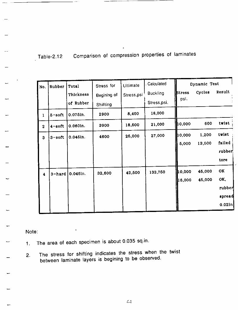
Table-2.12 Comparison of compression properties of laminates
No. Rubber Total
Thickness
of Rubber
1 5-soft 0.076in.
2 4-soft O.060in.
3 3-soft 0.046in.
4 3-hard 0.0451n.
Stress for Ultimate , Calculated
Begining of Stress,psi Buckling Stresspsi.
Shifting Stress ,psi.
2900 8.400 18,000
3900 18,500 21,000
4600 25,000 27,000
32.600 42,500 133,750
Dynamic Test
Cycles Result
IO,O00 600 twist
t0,000 1,200
5,000 13,500
twist
failed
rubbel
tore
lO,O00 45,000
16,000 45.000
OK
OK,
rubbel
spread
O.02ln
Note"
1.
2.
The area of each specimen is about 0.035 sq.in.
The stress for shifting indicates the stress when the twist
between laminate layers is begining to be observed.
,44
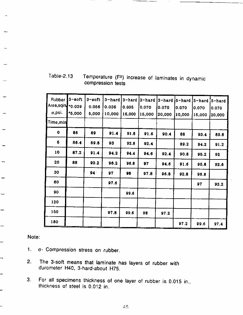
Note:
Table-2.13
Rubber
fArea,sqir_
_,psi.
Time,min
Temperature (F o) increase of laminates in dynamiccompression tests
3-sott
*0.039
"6,000
0-soft
0.056
6,000
3-hard 3-hard 3-hard
[0.070
15,000
3-hard 5-hard 5-hard 5-hard
0.035
I0,000
'0.035
16.000
91.6
0.070
20,000
!0.070
I0,000
0.070
15,000
0.070
20,000
0 86 89 91.4 91.8 90.4 88 93.4 89.8
6 86.4 89.8 98 92.8 92.4 89.2 94.2 91.2
10 87.2 91.4 94.2 94.4 94.6 92.4 90.8 95.2 92
20 88 93.2 96.2 96.8 97 94.6 91.6 95.8 92.6
30 94 97 98 97.8 96.8 92.8 96.8
60 97.6 97 93.2
90 99.6
120
150 97.8 99.6 98 97.2
180 97.2 99.6 97.4
1. _- Compression stress on rubber.
.
.
The 3-soft means that laminate has layers of rubber withdurometer H40, 3-hard-about H75.
For all specimens thickness of one layer of rubber is 0.015 in.,thickness of steel is 0.012 in.
_5
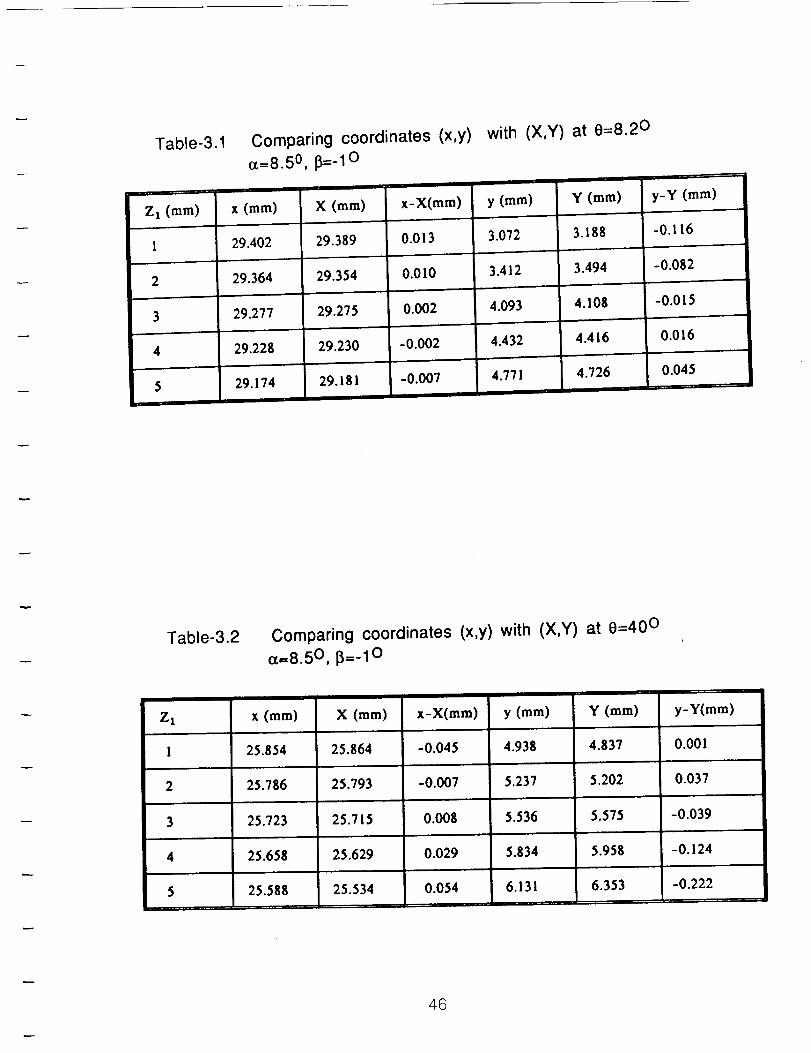
Table-3.1
Z t (ram)
2
5
Comparing coordinates (x,y)
o_=8.5 O, fY=-I 0
I
X (mm) x-X(mm)
0.013
0.010
0.002
-0.002
-O.OO7
with (X,Y) at 0=8.20
y (ram)
3.072
3.412
4.093
Y (ram)
3.188
3.494
4.108
4.416
y-Y (ram)
-0.116
0.016
0.045
x (ram)
29,402 29.389
29.364 29.354
29,277 29.275
29.228 29.230
29.174 29.181
4.432
4.771 4.726
Table-3.2 Comparing coordinates (x,y) with
ct=8.5 O, i_=_10
(X,Y) at 0=40 °
Z x x (mm) X (mm) x-X(mm) y (mm) Y (mm) y-Y(mm)
I 25.854 25.864 -0.045 4.938 4.837 0.001
2 25,786 25.793 -0.007 5.237 5.202 0.037
3 25.723 25.715
4 25.658 25.629
5=,
25.588 25.534
0,008 5.536 5.575 -0.039
5.834 5.958 -0.124
6.131 6.353 -0.222
0.029
0.054T
46
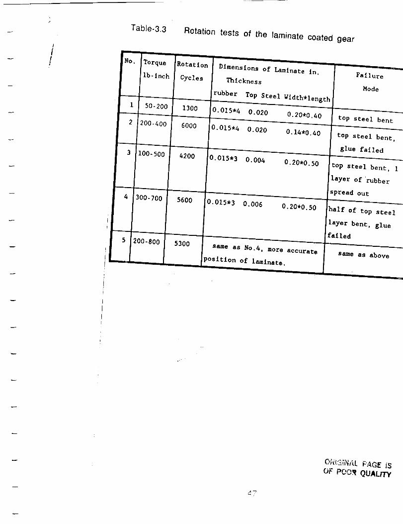
Table-3.3 Rotation tests of the laminate coated gear
I
i!t
No.
1
2
Torque
Ib-inch
Rotation
Cycles
Dimensions of Laminate in.
Thickness
rubber Top Steel Width*length
50-200 1300 0.015-4 0.020 0.20*0.40
, ,,,
200-400 6000 0.015.4 0.020 0.14"0.40
,,, ,=
3 I00-500
4:300-700
4200 0.015.3 0.004 0.20*0.50
5600 0.015"3 0.006 0.20*0.50
53OO5 200-800 same as No.4, more accurate
position of laminate.
Failure
Mode
top steel bent
top steel bent,
glue failed
top steel bent, I
layer of'rubber
spread out
half of top steel
layer bent, glue
failed
same as above
O_t_NI_L PAGE JE
OF POOff QUALIT_
A7
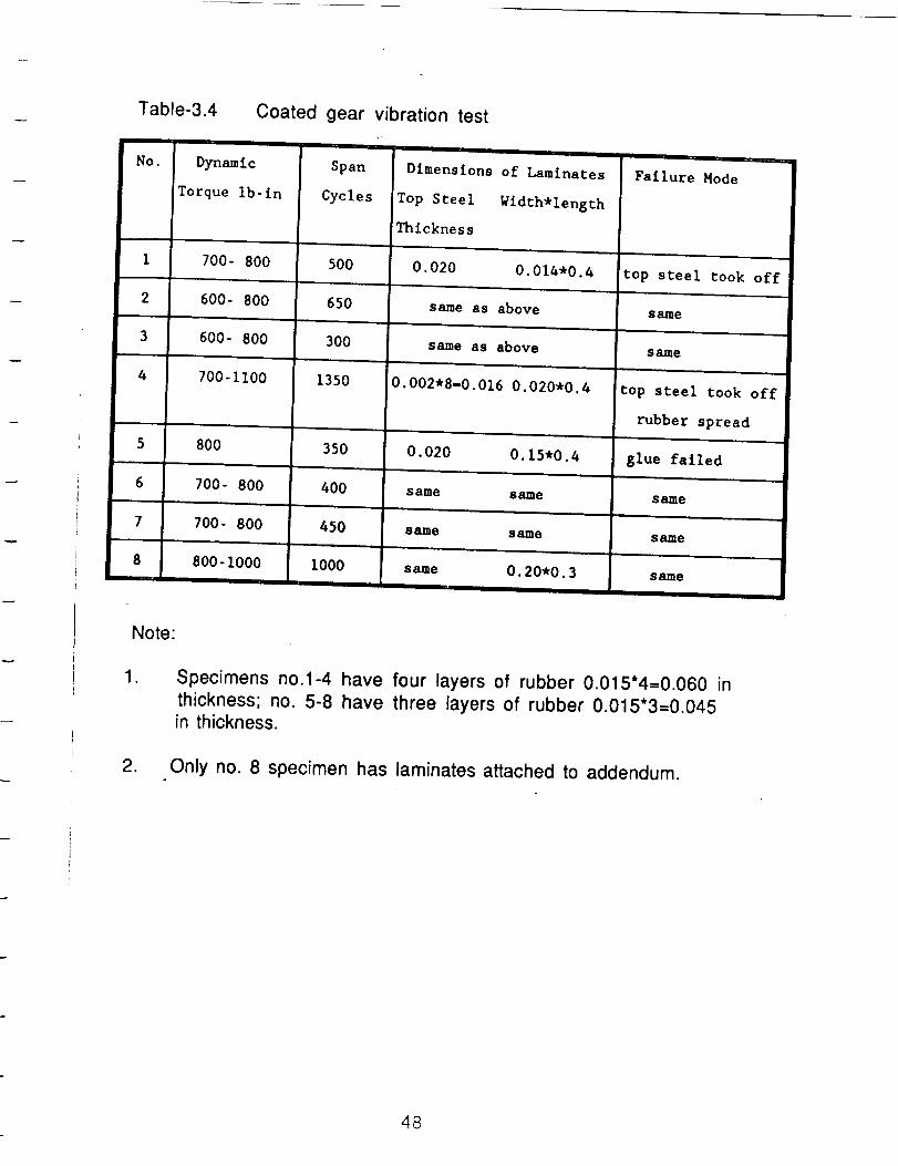
Table-3.4
NO.
1
2
3
4
Coated gear vibration test
Dynamic Span
Torque ib- in Cycles
700- 800 500
600- 800 650
600- 800 300
700-1100 1350
Dimensions of Laminates
Top Steel Width*length
Thickness
Failure Mode
5
6
7
8
8OO 35O,., , J ,
700- 800 400
700- 800 450
800-1000 I000
0.020 0.014"0.4 top steel took off
same as above same
same as above same
0.002"8-0.016 0.020*0.4 top steel took off
rubber spread
0.020 0.15.0.4 glue failed
same same same
s_me same ssJme
same O. 20*0.3 same
Note:
1.
.
Specimens no.1-4 have four layers of rubber 0.015"4=0.060 in
thickness; no. 5-8 have three layers of rubber 0.015"3=0o045
in thickness.
Only no. 8 specimen has laminates attached to addendum.
48
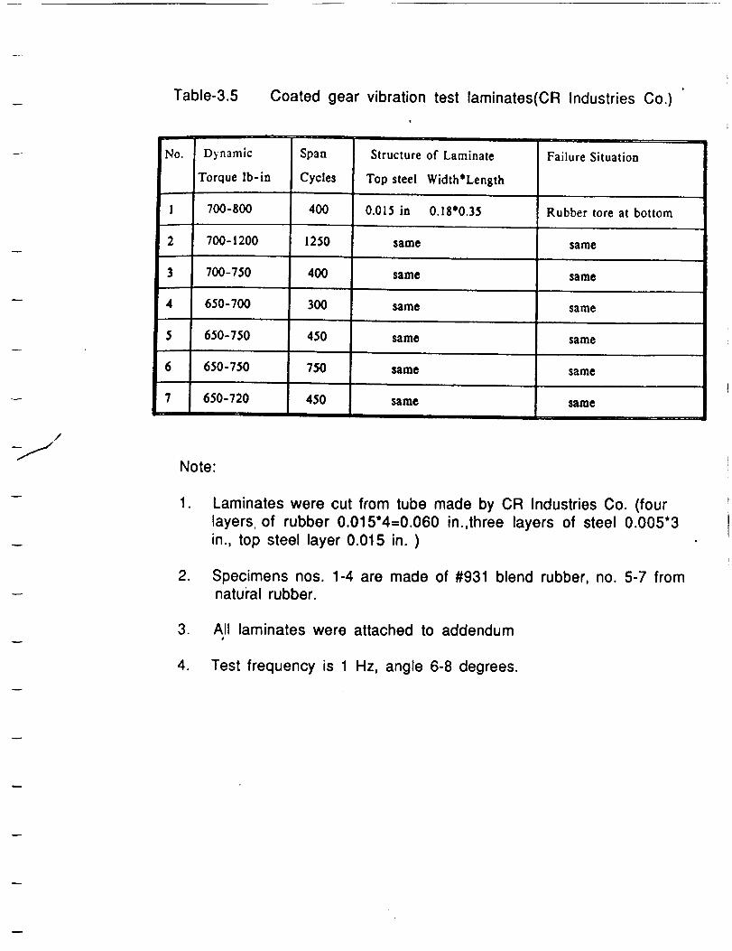
m
Table-3.5 Coated gear vibration test laminates(CR Industries Co.)
No.
1
2
3
4
5
6
7
Dynamic
Torque Ib-in
700-800
700-1200
700-750
650-700
650-750
650-750
650-720
Span Structure of Laminate
Cycles Top steel Width*Length
400 0.015 in 0.18'0.35
same
same
same
same
same
same
1250
400
300
450
750
450
Failure Situation
Rubber tore at bottom
same
same
same
same
same
same
/
Note:
. Laminates were cut from tube made by CR Industries Co. (four
layers of rubber 0.015"4=0.060 in.,three layers of steel 0.005*3
in., top steel layer 0.015 in. )
. Specimens nos. 1-4 are made of #931 blend rubber, no. 5-7 fromnatural rubber.
. All laminates were attached to addendum#
4. Test frequency is 1 Hz, angle 6-8 degrees.
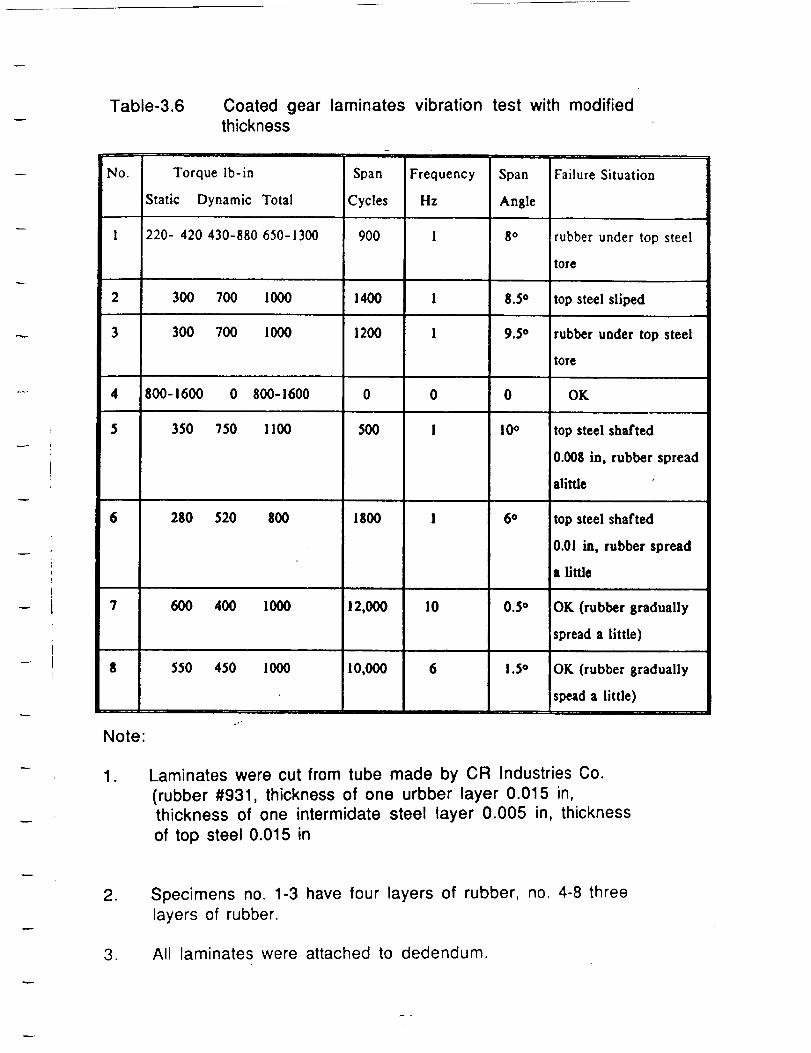
Table-3.6 Coated gear laminates vibrationthickness
No. Torque ib-in Span Frequency
!Static Dynamic Total Cycles Hz
I 220- 420 430-880 650-1300
test with modified
Span
Angle
900 1 8°
2 300 700 I000 1400 I
3 300 700 I000 1200 I
4 800-1600 0 800-1600 0 0
$ 350 750 I100 500 i
Failure Situation
rubber under top steel
tore
8.5 ° top steel sliped
9.5 ° rubber under top steel
tore
0 OK
10o
6 280 520 800 1800 1 6°
top steel shafted
0.008 in, rubber spread
alittle
top steel shafted
0.01 in, rubber spread
a little
7 600 400 1000 12,000 10 0.5 ° OK (rubber gradually
spread a little)
$ 550 450 1000 10,000 6 1.5 ° OK (rubber gradually
spead a little)
Note:
1. Laminates were cut from tube made by CR Industries Co.
(rubber #931, thickness of one urbber layer 0.015 in,thickness of one intermidate steel layer 0.005 in, thickness
of top steel 0.015 in
.
,
Specimens no. 1-3 have four layers of rubber, no. 4-8 three
layers of rubber.
All laminates were attached to dedendum.
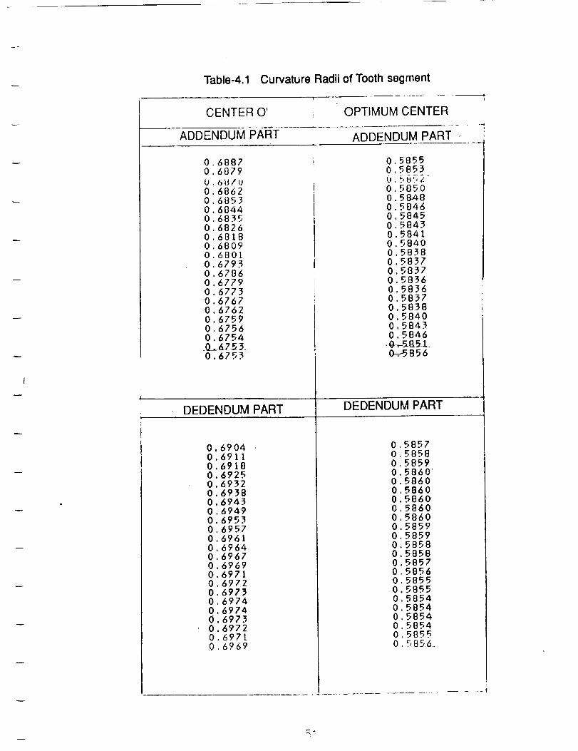
I
Table-4.1 Curvature Radii of Tooth segment
I
CENTER O' OPTIMUM CENTER
ADDENDUM PART ADDENDUM PART ,
0 68870 6879
U 6U/U0 68620 68530 60440 68350 68260 68180 68090 68010 67930 67860 67790 67730 67670 67620 67590 67560 6754.0_._67.53.0.6753
DEDENDUM PART
0 58550 5853
U 5U?,L0 58500 58480 58460 58450 58430 58410 58400 58580 58370 58370 58360 58360 58370 58380 58400 58430 5846
.g_-SBS.L0-_-5856
DEDENDUM PART
000000000000000000Q
0000
.6904691169186925693269386943
.6949
.6953
.69576961696469676969697169726973697469746973697269716969
0.58570.58580.58590.58600.58600 58600 58600 58600 58600 58590 58590 58580 58580 58570 58560 58550 58550 58540 58540 58540 58540 58550 5856_
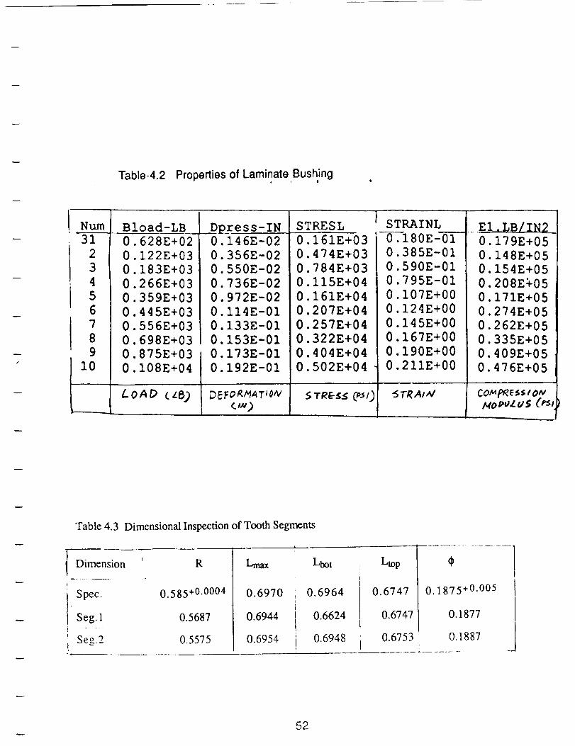
Table-4.2 Properties of Laminate Bushing
Nun%
31
2
3
4
56
7
89
I0
Bload-LB
0.628E+02
0.122E+03
0.183E+03
0.266E+03
0.359E+03
0.445E+03
0.556E+03
0.698E+03
0.875E+03
0.I08E+04
.D_ress-IN0.146E-02
0.356E-02
0.550E-02
0.736E-02
0.972E-02
0.I14E-01
0.133E-01
0.153E-01
0.173E-01
0.192E-01
LOAD (z8) D_F_T/oNc,x)
STRESL
0.161E+03
0.474E+03
0.784E+03
0.I15E+04
0.161E+04
0.207E+04
0.257E+04
0.322E+04
0.404E+04
0.502E+04
STRAINL
i-0--_80E-010.385E-01
0.590E-01
0.795E-01
0.107E+00
0.124E+00
0.145E+00
0.167E+00
0.190E+00
0.211E+00
"5TRA/ _
0.179E+05
0.148E+05
0.154E+05
0.208E%05
0.171E+05
0.274E+05
0.262E+05
0.335E+05
0.409E+05
0.476E+05
Ho pcZ US (_/
Table 4.3 Dimensional Inspection of Tooth Segments
Dimension
L ..
Spec.
Seg. 1
Seg.2
R
0.585+0.0004
0.5687
0.5575
Lm_
0.6970
0.6944
0.6954
Lbot
t
10.6964i
r
I 0.6624
0.6948i
Ltop
0.6747
0.6747
0.6753
0. 1875+0.005
0.1877
0.1887i
52
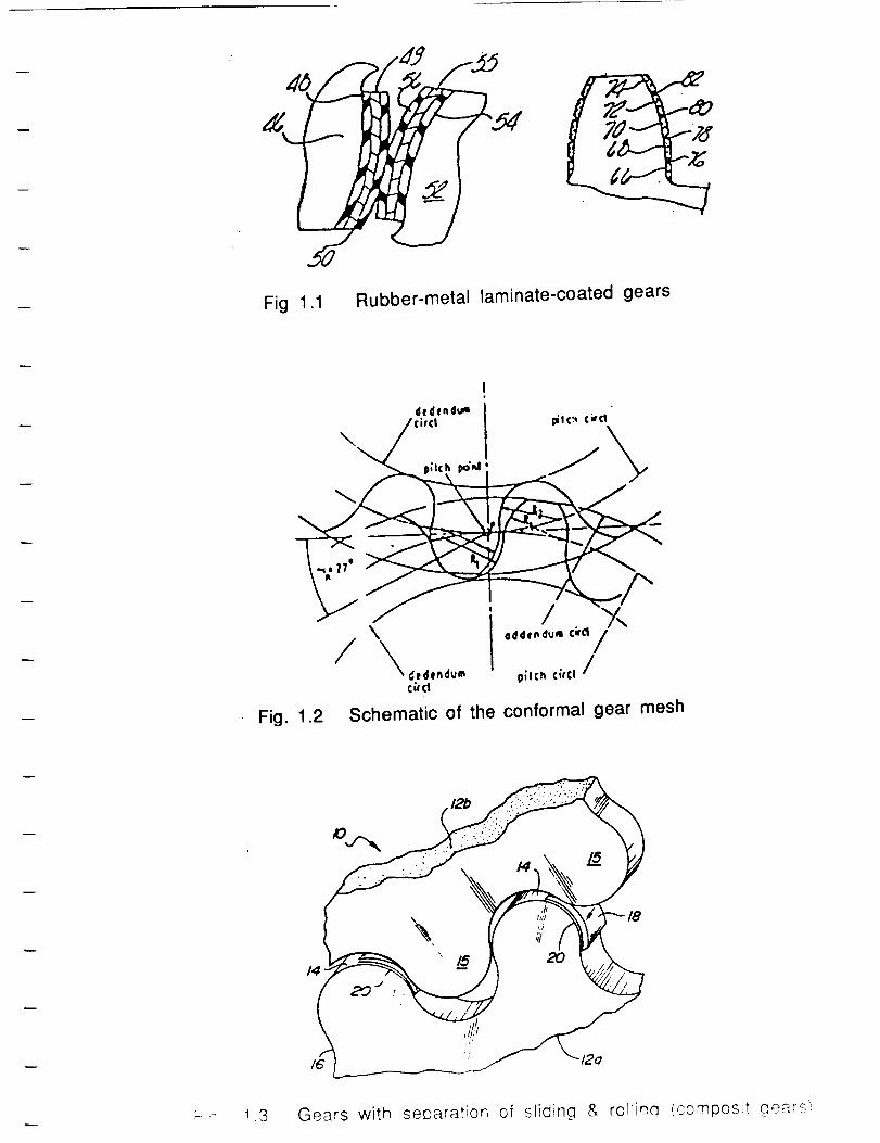
Fig 1.1 Rubber-metal laminate-coated gears
de_tnd_,w
, /'ci_'cl _rc_ cvce
/ \\ [ .,,._,-.'°,,/
_edtn_um p;Ich C;rCl /CirCl
Fig. 1.2 Schematic of the conformal gear mesh
( 12b
18
14
I
r--' 1 '3 Gears with separation of sliding & rollinq (compos,t _ -
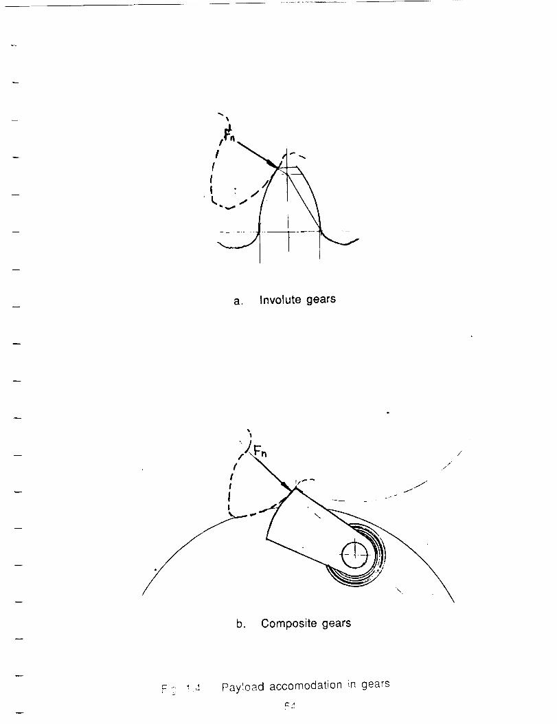
IL
a. Involute gears
f;_ //" /
b. Composite gears
F ,_ !4 Payload accomodation in gears
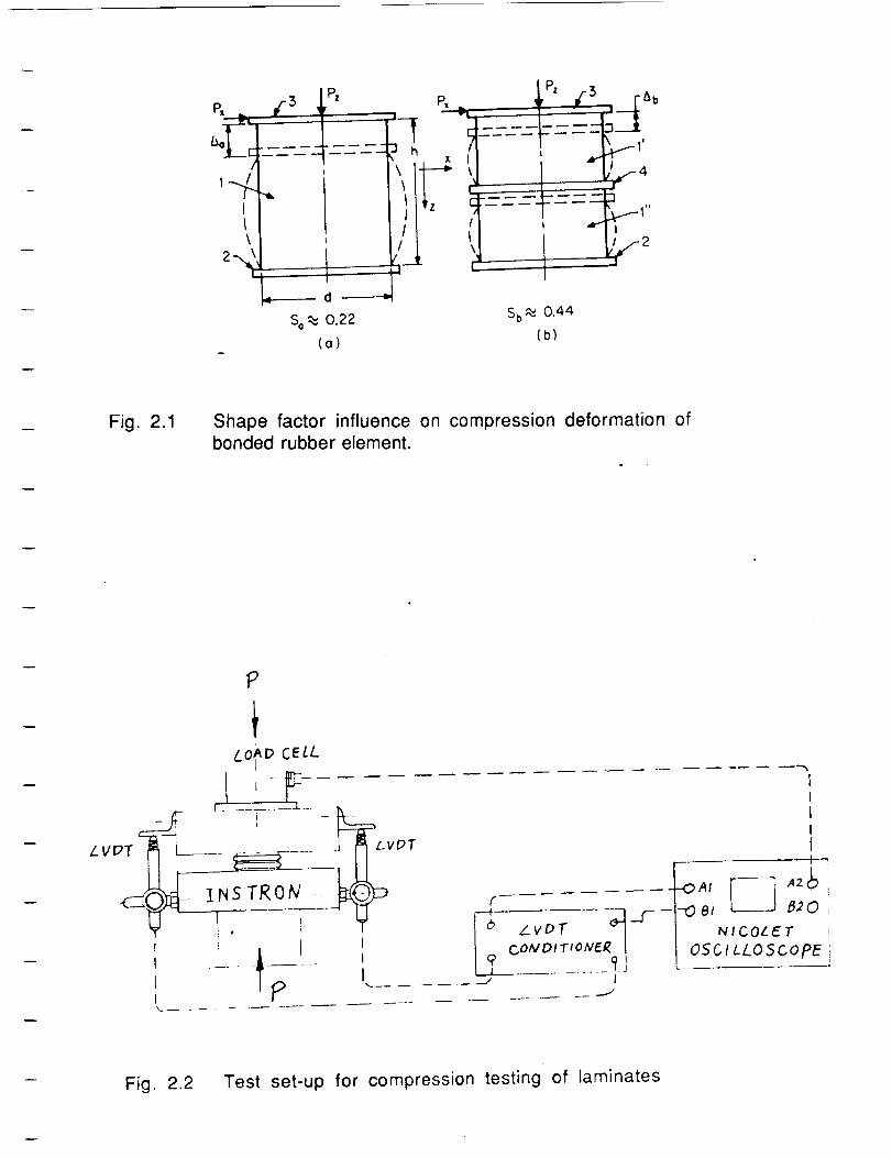
p, -3 1,P'
I
\
P,
{
/I\,t"
_- - -_---!___._
I _1.I_ 1,
- lJf4
_------- d
So _ 0.22 Sb_ 0.44
(o) (b)
Fig. 2.1 Shape factor influence on compression deformation ofbonded rubber element.
-- I .. L_.
Lvpr L__ ......... ] _ Lv_T
-f?-- ,'\
?
LO_D CELL
I
COIVDIT_ONER I_L_.......... __-J I
II
III
NICOLET
OSCtLLO5copE
Fig. 2.2 Test set-up for compression testing of laminates
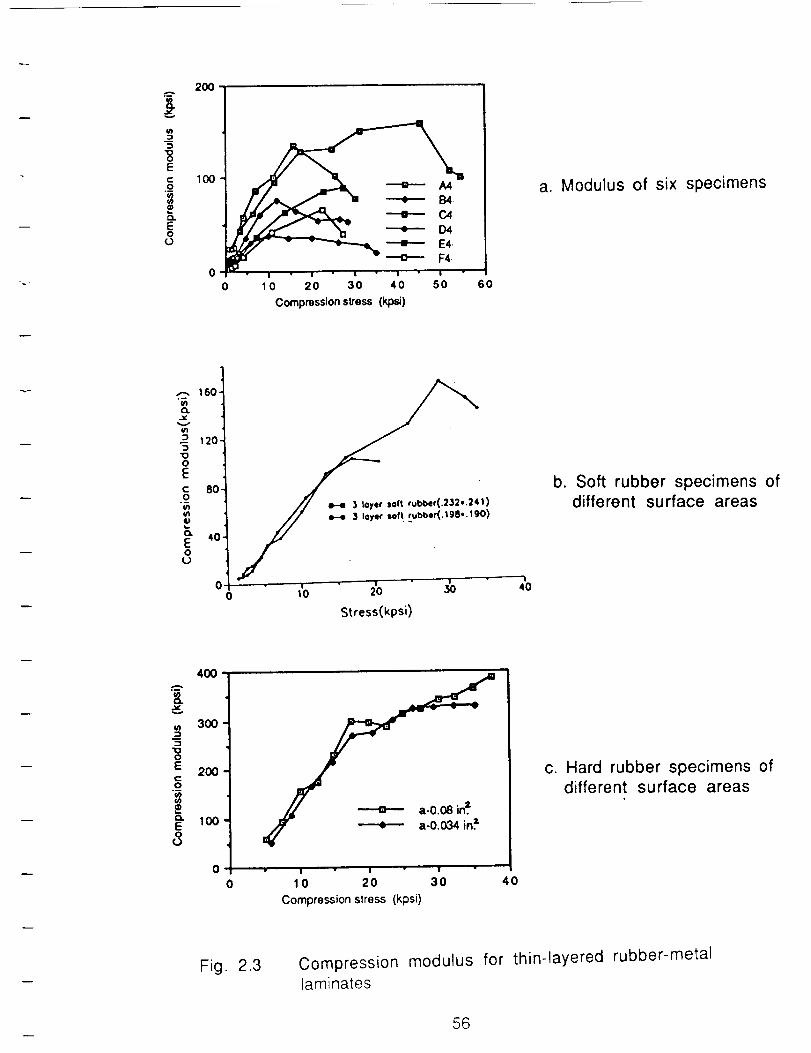
._ 100
Eo --,,---- 040
0 _ ---o---- F4
0 10 20 30 40 50 60
Compression stress (kpsl)
a. Modulus of six specimens
.-.. 160.
C_
120."5"10oEc 80,o
tV
E 4oo
u
1)
" 1 " I " | "
10 20 ,30
Stress(kpsi)
40
b. Soft rubber specimens ofdifferent surface areas
400
8.
300
-5"100
E 2OO¢0
" 100E
8
0I I I
10 20 30
Compression stress (kpsi)
40
c. Hard rubber specimens ofdifferent surface areas
Fig. 2.3 Compression modulus for thin-layered rubber-metallaminates
56
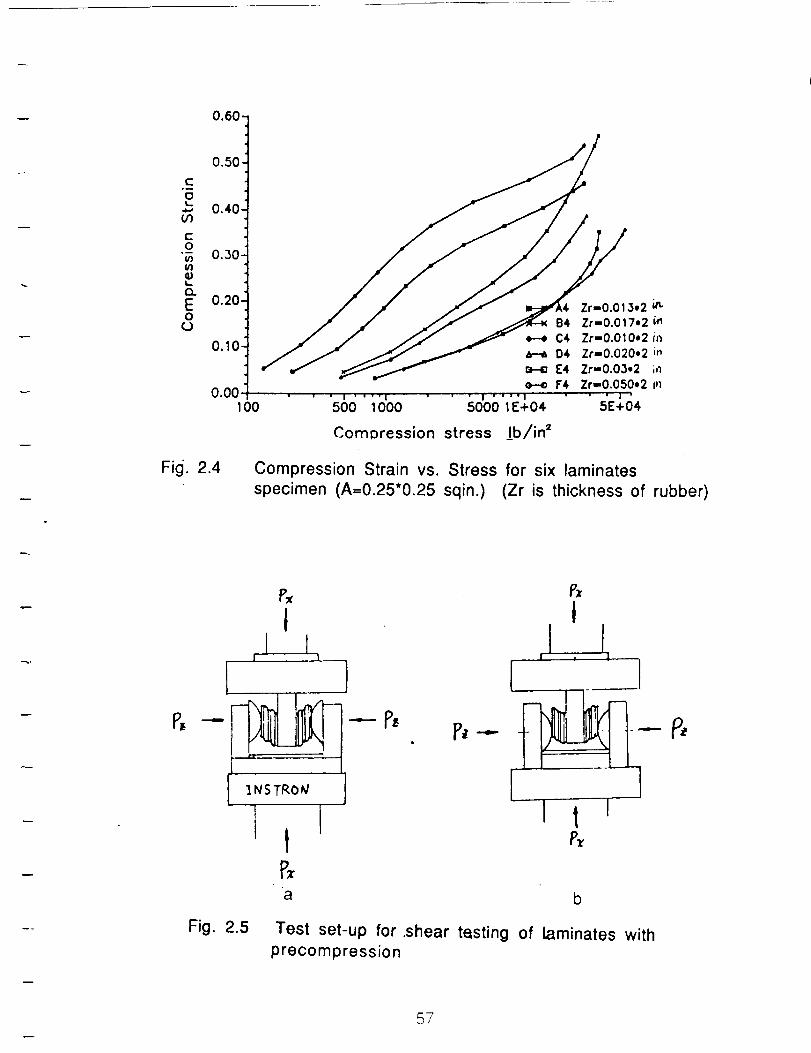
0'601
0.50
c
g 0"401
"__ 0'301
,_ f_----_-_ H E4 Zr-O.03,2 in
o.oot , . , .. _.,,.,, , .... --.--,_..Zr-_.,O_y.2-" ""_oo soo;ooo sooo_,o4 s_+o4
Comoression stress ]b/in =
Fig. 2.4 Compression Strain vs. Stress for six laminates
specimen (A=0.25"0.25 sqin.) (Zr is thickness of rubber)
P,
Fig. 2.5
1NSTRO_/
a
tJ
m !
I •
Test set-up for .shear tasting of laminates with
precompression
57
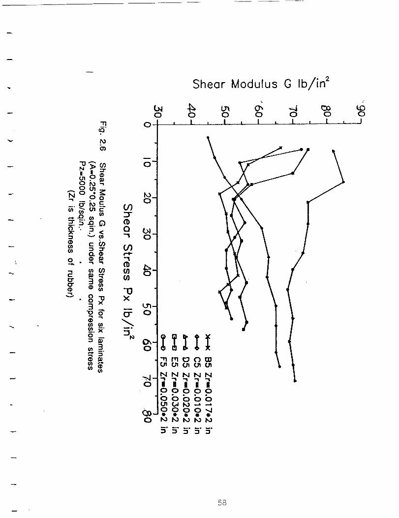
-rlm°
113
t_b_
N
(.;1oi_
I/I
Z 5".£_. 6)".
_- .
l- (/)
n III0 _
• "1 _1
_ Or)
•,_ 0 "13° 0 x
3_,,"10 0
__.N"0
_3_'5"
She0r Modulus O Ib/in 2
la40
O
O"
UO
"13X
Mrl.m
lur o
0 0 0 0i ...l i 1 , I L. L
0
_NNNN
o &&&&&
0 0! ..[ [ .I
/
58
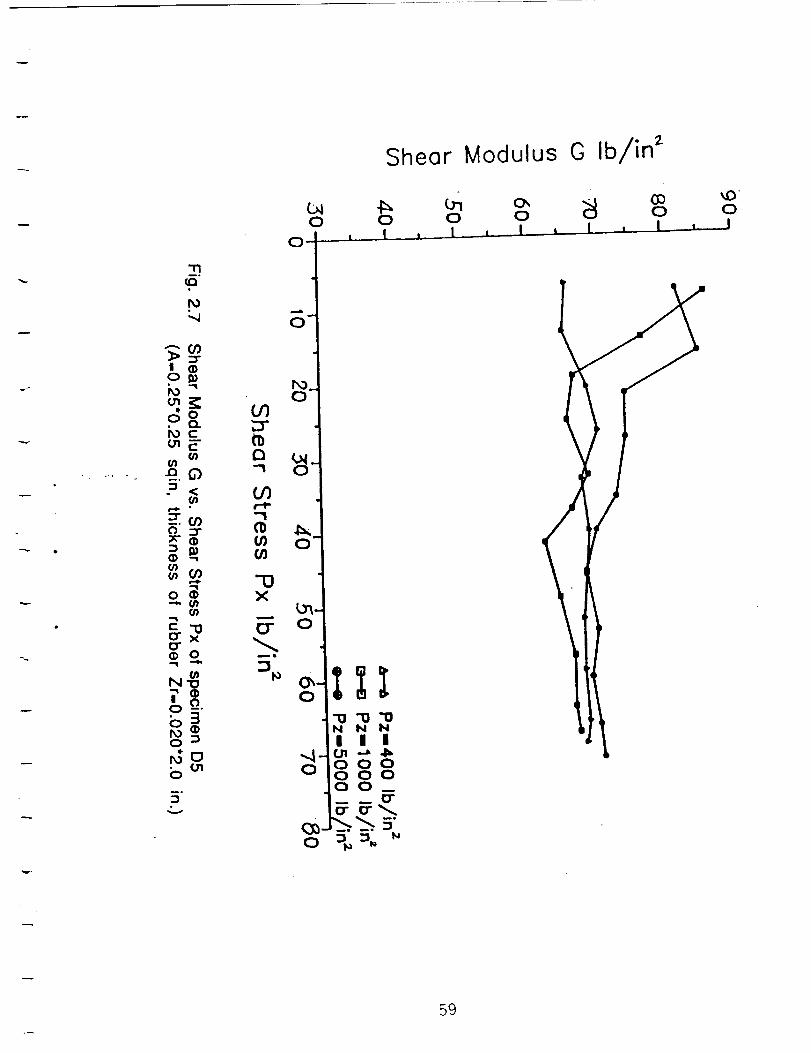
Shear Modulus G Ib/in 2
_0030 0 0 0 0 0
O-
"11
O"
"- O0
I01_
i_-" _.
0• n
if)
_ c_E (1)
_ °_ _o--____"
g_
o_.
b
3" £1;:_E -- --
0 _ _
59
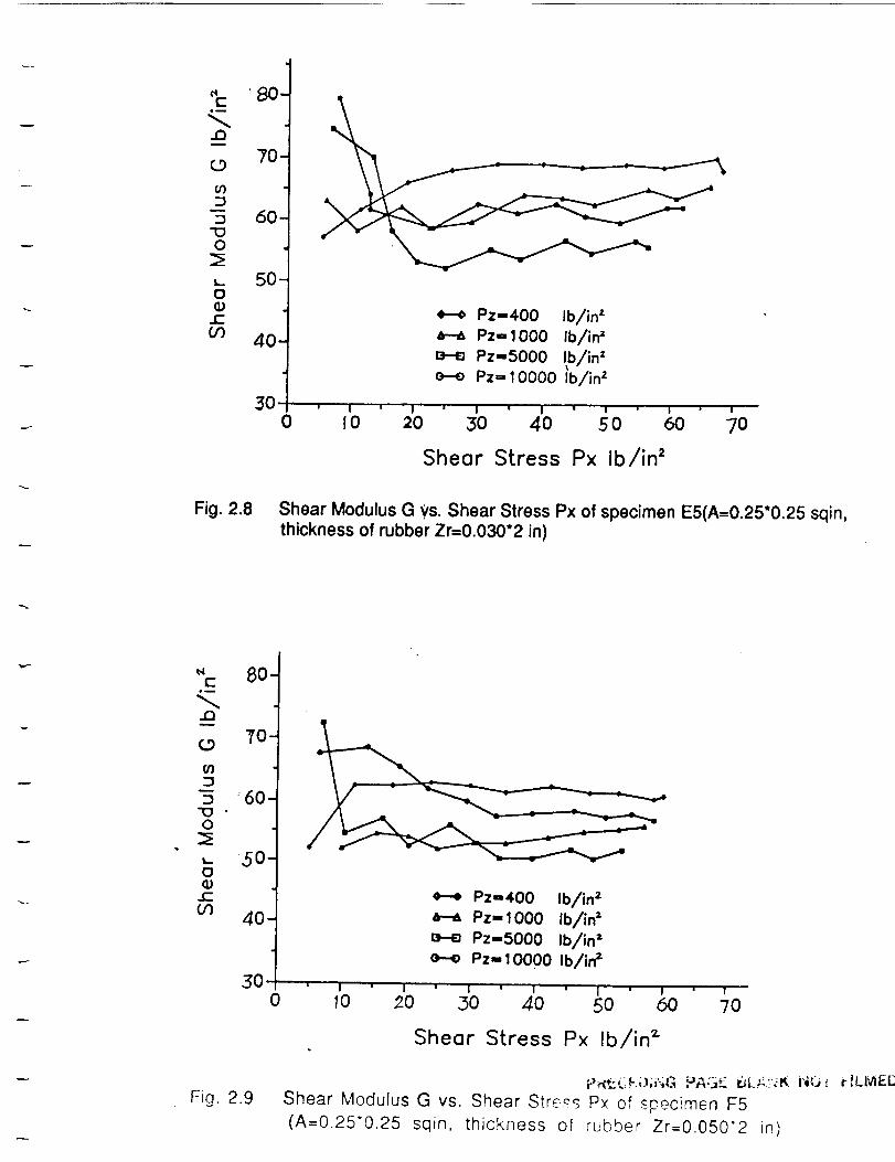
elE
eu
J3
(.9
:3
"IDO:sI,..
{36)t-
OO
80-
70-
6O
5O
40
50
Pz-400 Ib/in"Pz-lO00 Ib/ir_
Pz-5000 !b/in'e---e Pz= 10000 Ib/in 2
I ' I ' I ' I ' I ' I ' a
0 l 0 20 30 40 5 0 60 70
Shear Stress Px ib/in 2
Fig. 2.8 Shear Modulus G ys. Shear Stress Px of specimen E5(A=0.25*0.25 sqin,thickness of rubber Zr=0.030*2 in)
" 80-¢-e_
t_
7o.
O3
-5:60"(3 •0
_- 50-0
c-
_ 40.
Fig. 2.9
Pz-400 Ib/in =
Pz- 1000 Ib/in =
Pz-5000 Ib/in =e--e Pz- 10000 Ib/in =
.30 , , , , • , ,' t' ,
0 10 _0 30 40| ' I ' !
50 60 70
Shear Stress Px Ib/in _
_Z(F i._;i.;G PAGE 6L;_,.?-_Is, NQ., r ;LiVt,-i.;
Shear Modulus G vs. Shear Stre£_ P× of specimen F5
(A=0.25"0.25 sqin, thickness of rubber Zr=0.050*2 in)
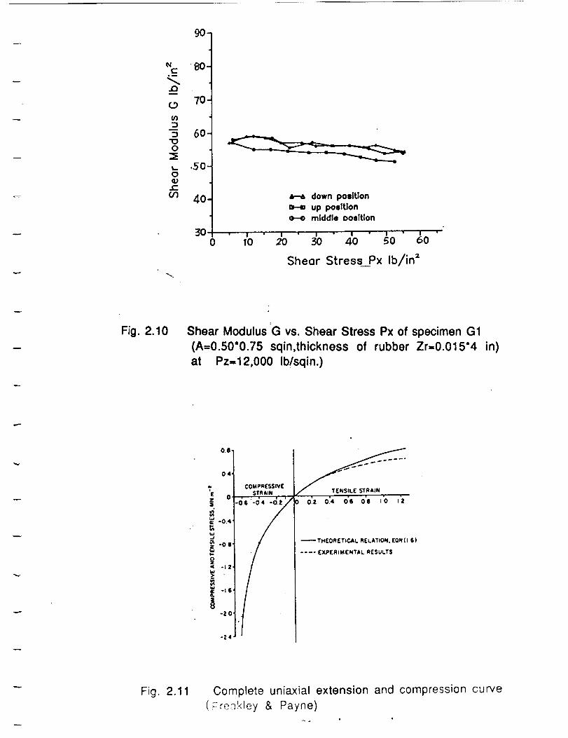
C.w
(.9
03
O
t_
O
(1)¢-
03
90 N
80.
70.
60.
.50-
40-
50" " I
0 tO
a--_ down poilUon
H up poslUon
H middle oosRion
• I ' I " I " I'" " I
2O 30 40 50 60
Shear Stress__Px Ib/in 2
Fig. 2.10 Shear Modulus G vs. Shear Stress Px of specimen G1
(A=0.50"0.75 sqin,thickness of rubber Zr=0.015*4 in)
at Pz=12,000 Ib/sqin.)
E
| o :_6'-d4:-_
.J
_ -0 |"
_ -I 2"
A-ZO .
-14
0.ll.
04
COMPRESSIVE
$TRJIN
) 0.=3 0.4 06 011 ;0 !Z
THEORETICAL RELATION, [ON (I I )
.... EXPERIMENTAL RESULTS
Fig. 2.11 Complete uniaxial extension and compression curve
(Freakley & Payne)
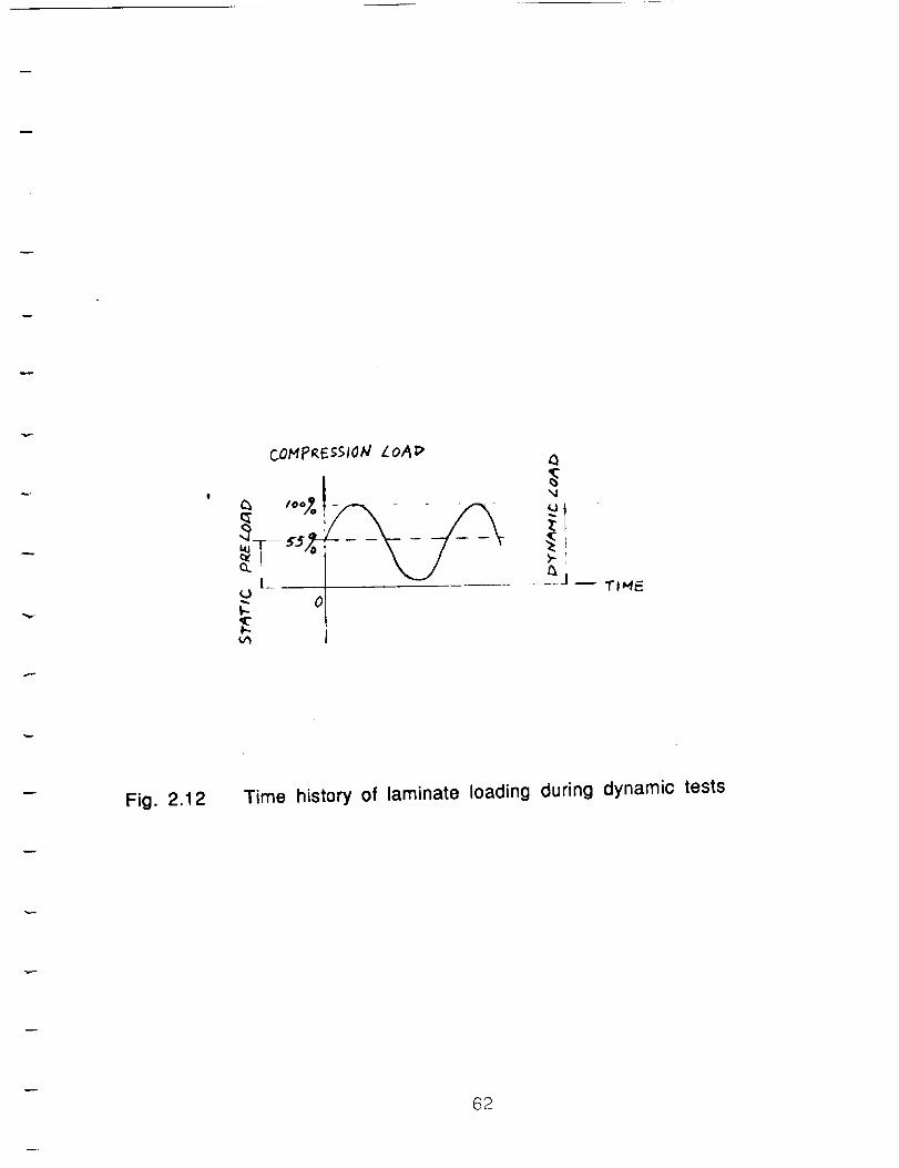
COMIPRES$1OW LoA_
ca t**_.
k-- 0
Q
',4
J _ TPHE
Fig. 2.12 Time history of laminate loading during dynamic tests
62
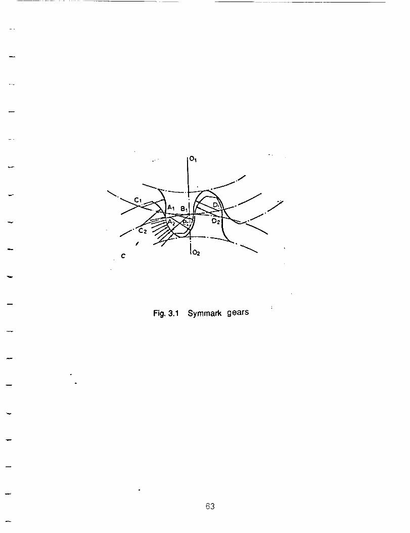
° .
.. - o[ .._./
/ i-/ _-._C i02
Fig. 3.1 Symmark gears
63
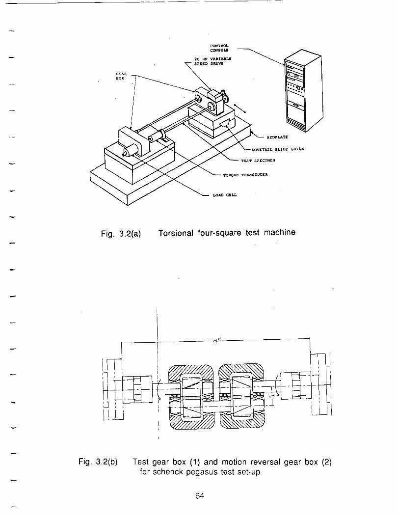
GEAR
BOX
%JBEDpLATE
DOV_TA/L SLIDZ GUIDE
TEST SPECIP4EN
TOQUE TRANSDUCER
Fig. 3.2(a) Torsional four-square test machine
_L
q1
i
J
T__ m I
:1--;-'
L i
Fig. 3.2(b) Test gear box (1) and motion reversal gear box (2)
for schenck pegasus test set-up
64
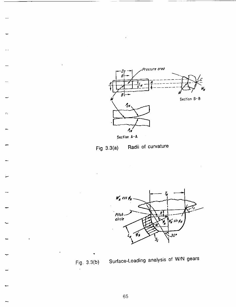
-B2o-,'-1.1pressure
A - I / L "-4
7_- •M
Section A-A
Qr#G
Section B-B
Fig 3.3(a) Radii of curvature
Fig. 3.3(b)
/ _ ,"#dw_;s/n#x,
Surface-Loading analysis of W/N gears
65
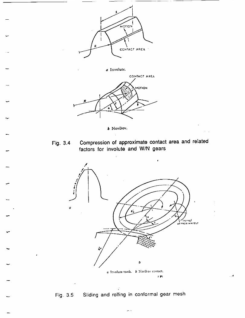
AREA
(z Involute.
CONTACT A R _._..,;.,
Fig. 3.4
b Novikov.
Compression of approximate contact area and related
factors for involute and W/N gears
.,4
Fig. 3.5
(
Sliding and rolling in conformal gear mesh
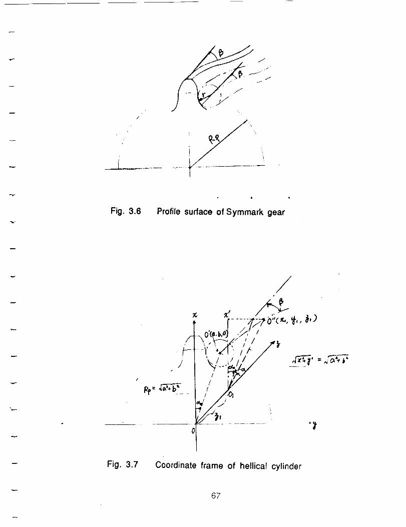
i
Fig. 3.6Profile surface of Symmark gear
Fig. 3.7
/-
/
Js
•\0( ._,,
/
1/
Coordinate frame of hellical cylinder
67
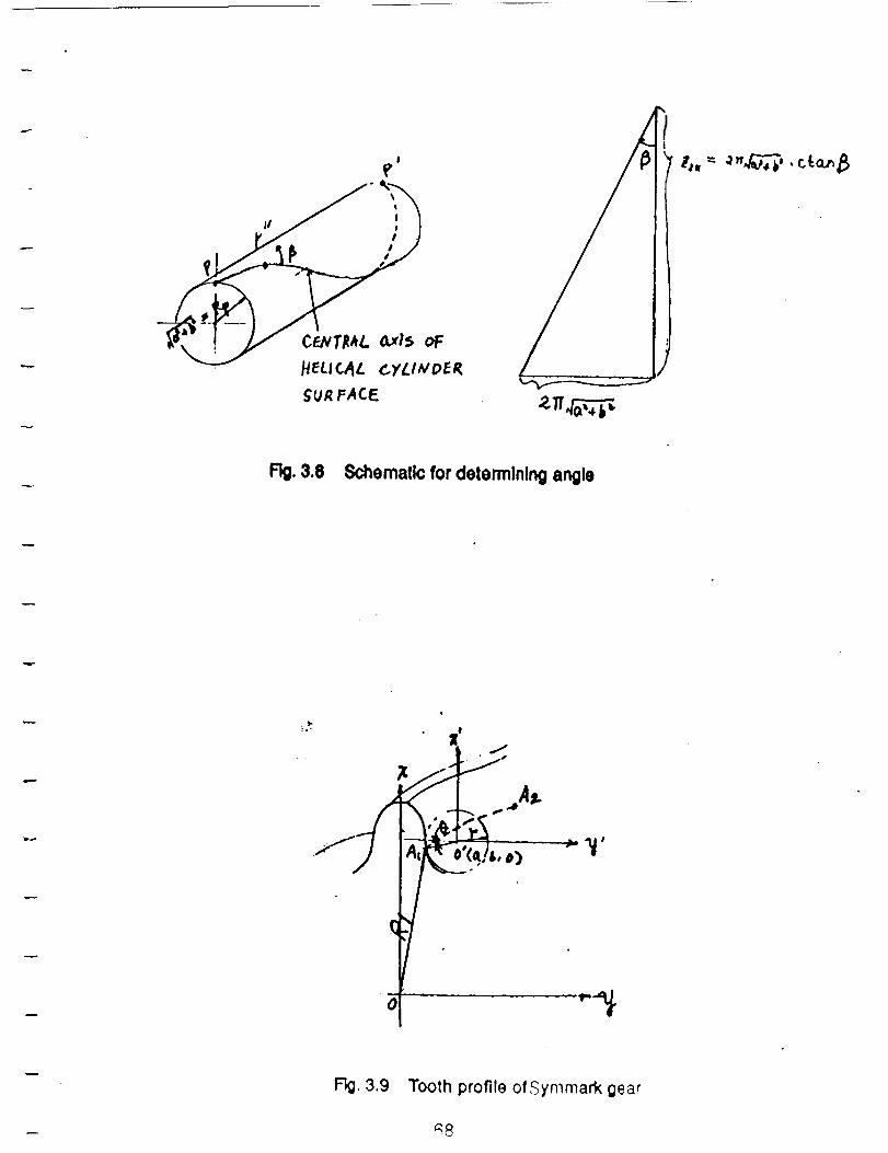
!
H_UCAL CyLt_PE_
_UR /=ACE
, , J
Fig.3.8 Schematic for dotormlnlng angle
:.-
x_ ''4_
• - _
• _
.o-T ,_
F3g.3.9 Tooth profile of Symmark gear
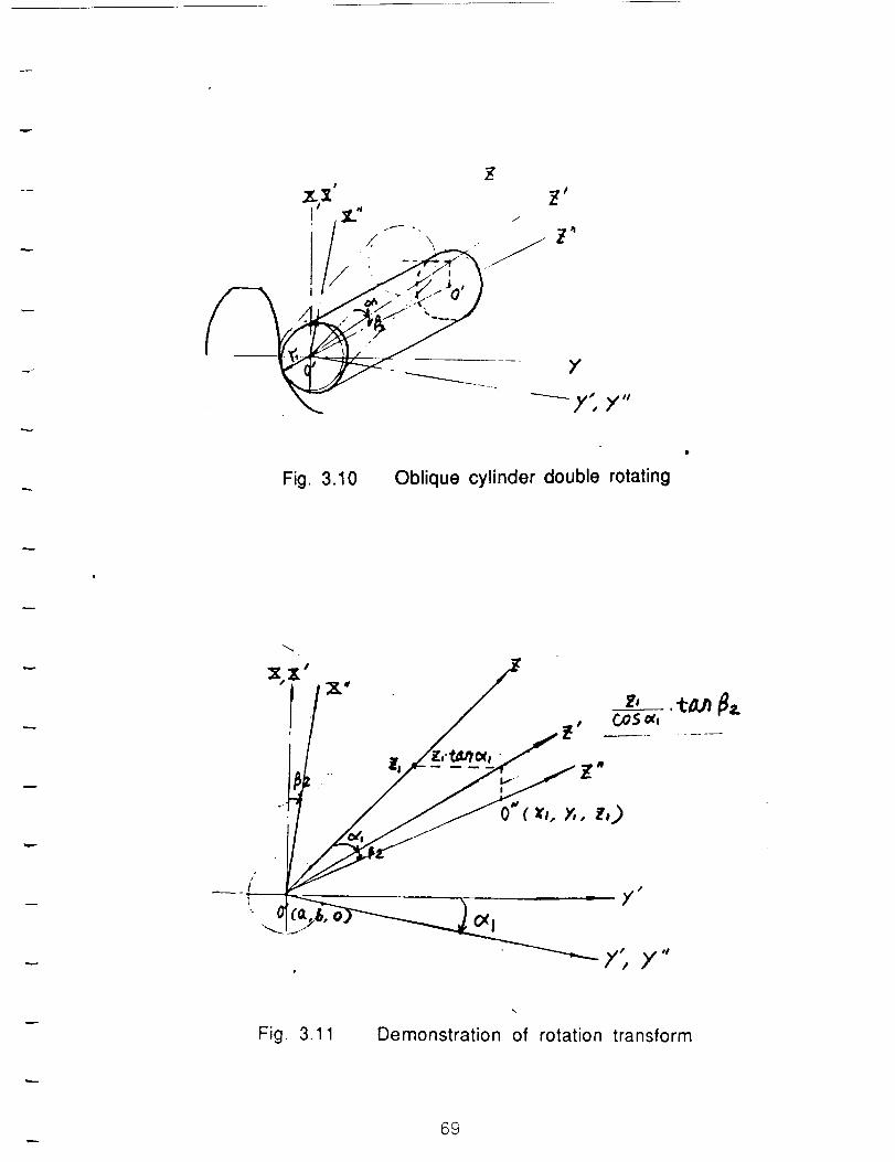
_y', ×,,
Fig. 3.10 Oblique cylinder double rotating
,-,...
x.x'x" /_
_" . __
f; ×"
Fig. 3.11 Demonstration of rotation transform
69
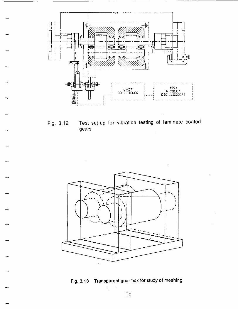
II
i i
LVDT ' 4094 ,i i
CONDITIONER ', NICOLET ,
r---4 k .... -I OSCILLOSCOPE ii i i i i
i_ .................. _ L. ......................' Iii i
.............. j
Fig. 3.12 Test set-up for vibration testing of laminate coated
gears
Fig. 3.13 Transparent gear box for study of meshing
7O
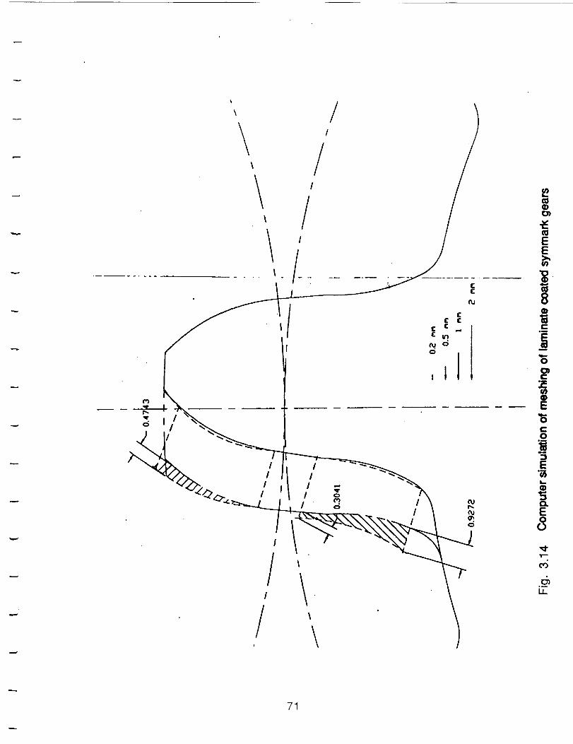
\
\\
/!
!!
.--
I.I_
71
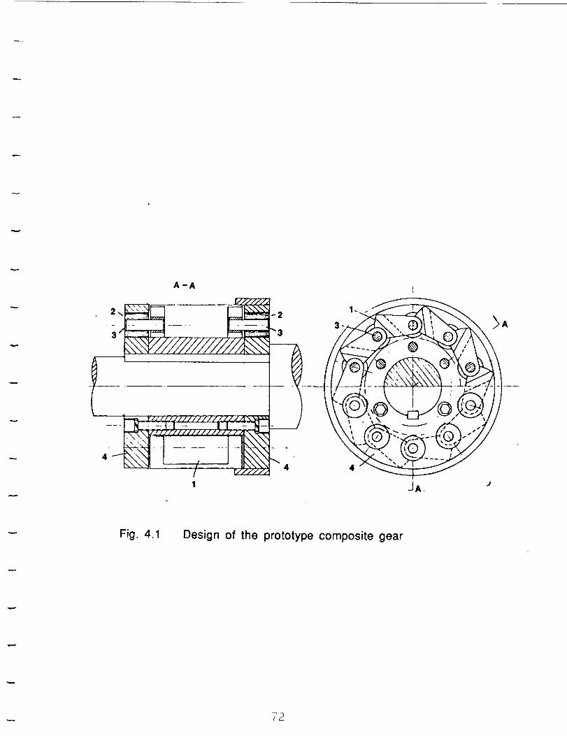
I -JA. +'
Fig. 4.1 Design of the prototype composite gear
72
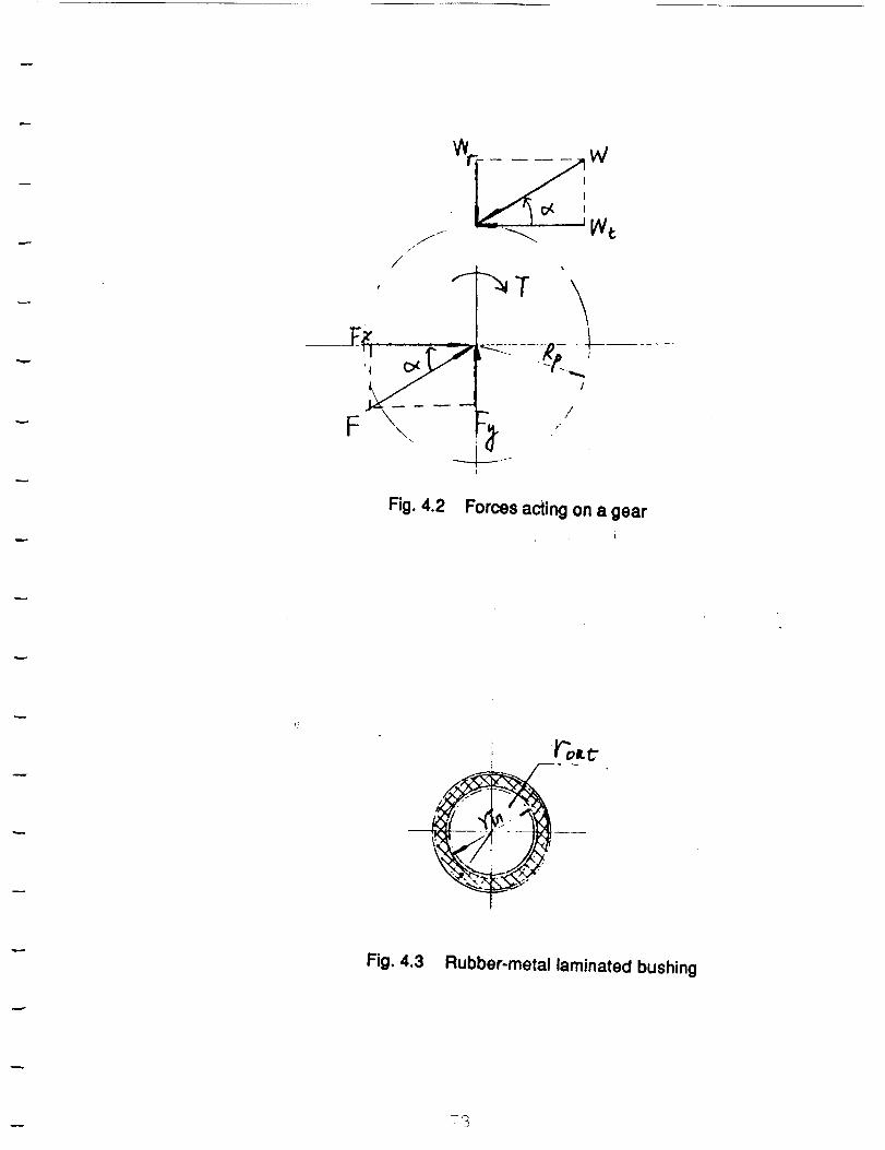
Fig. 4.2 Forces acting on a gear
Fig. 4.3 Rubber-metal laminated bushing
73
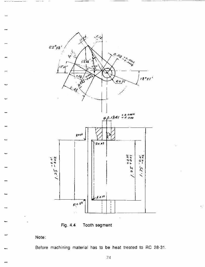
, \\ r\//_ % "%
// I ""
---N
<
T-
V .4
• Ro.e2
O. 000(/
_,lSaE/ .6 a, ooo
1
t_
% -,i
'1, 1I
I I
' 1I .
.
Fig. 4.4 Tooth segment
Note:
Before machining material has to be heat treated to RC 28-31.
74
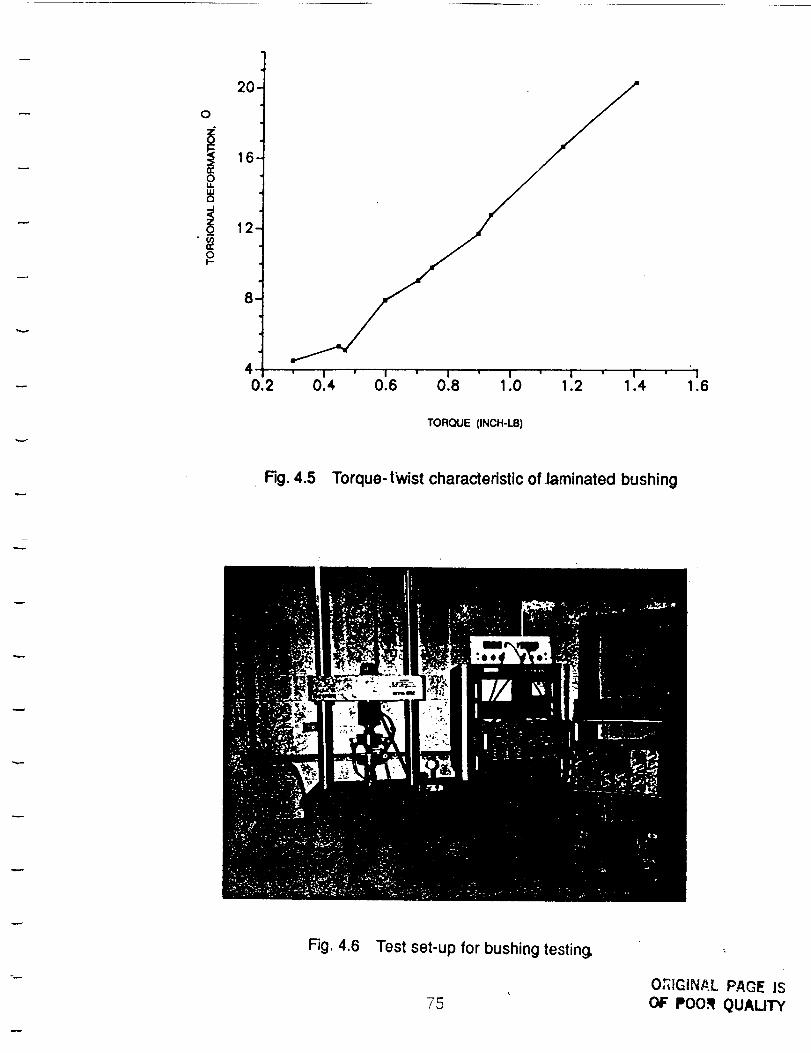
O
20-
i 16n-O14.U.I
E3
12
8
40.2
' I ' I ' I ' I ' ' I ' I0.4 0.6 0.8 1.0 1.2 1.4
I1.6
TORQUE (INCH-LB)
F',:j. 4.5 Torque-twist characteristic of ]aminated bushing
Fig. 4.6 Test set-up for bushing testing,
75OCt[GiNP.L PAGE ISOF POO._ QUALITY
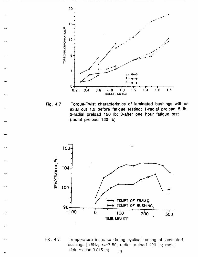
20-
16.O
_ 12.oLUQ
U)n"OI.--
,
00.2
/.,,,J,/
f-,i
/
/ jy,/
' I ' 1' ' I ' i " I I ' ! ' I
0.4 0.6 0.8 1.0 1.2 1.4 1.6 1.8TORQUE, INCH-LB
Fig. 4.7 Torque-Twist characteristics of laminated bushings without
axial ,cut 1,2 before fatigue testing; 1-radial preload 5 Ib;
2-radial preload 120 Ib; 3-after one hour fatigue test
(radial preload 120 Ib)
108-
LL
i 104-
loo-
mi
96.- O0
H TEMPT OF BUSHING',It
i ' I ' I ' I
0 100 200 300
TIME, MINUTE
Fig. 4.8 Temperature increase during cyclical testing of laminated
bushings (f=5Hz;o_=+7.50; radial preload 120 lb; radial
deformation 0.015 in) 76
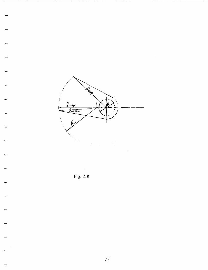
./."//_
'\_ I
Fig. 4.9
77
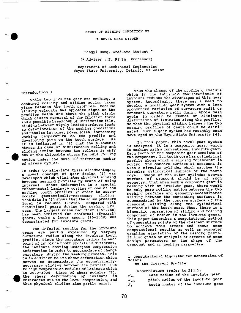
STUDY OF MESHING CONDITION OF
A NOVEL GEAR SYSTEM
Bangyi Dong, Graduate Student *
(* Adviser : E. Rivin, Professor)
Department of Mechanical Engineering
Wayne State University, Detroit, MI 48202
introduction :
While two involute gear are meshing, a
combined rolling and sliding action takes
place between the tooth profiles. Because
sliding velocity has opposite signs on the
profiles below and above the pitch circle
which causes reversal of the friction force
and a possible breakdown of lubrication film,
sliding between highly loaded surfaces leads
to deterioration of the meshing conditions
and results in noise, power loses, increasing
working temperature on the profile and
developing pits on the tooth surface. As
it is indicated in [i] that the allowable
stress in case of simultaneous rolling and
sliding action between two rollers is only
50% of the allowable stress for pure rolling
action under the same 106 reference number
of stress cycles.
In order to alleviate these disadvantages,
a novel concept of gear design [2] was
developed which eliminates physical sliding
between meshing profiles by means of using
internal shear deformation in a special
rubber-metal laminate coating on one of the
meshing tooth profiles in order to accom-
modate geometrically-necessary sliding.
Test data in [2] shows that the sound pressure
level is reduced 10-20dB compared with
traditional gears during the meshing pro-
cess. The largest noise reduction (15-20dB)
has been achieved for conformal (Symmark)
gears, while a lower amount (10-15dB) was
demonstrated for involute gears.
The inferior results for the involute
gears are partly explained by varying
curvature radius along the involute tooth
profile. Since the curvature radius in each
point of involute tooth profile is different,
the laminate coating undergoes compression
deformation in order to accommodate of change
curvature during the meshing process. This
is in addition to its shear deformation which
serves to accommodate the geometrically-
necessary sliding between the profile. Due
to high compression modulus of laminate which
is 2000-3000 times of shear modulus [3],
the shear deformation of laminate is
obstructed due to the local compression, and
thus physical sliding also partly exist.
Thus the change of the profile curvature
which is the intrinsic characteristic of
involute reduces the advantages of this gear
system. Accordingly, there was a need to
develop a modified gear system with a less
pronounced variation of curvature radii or
constant curvature radii during whole mesh
cycle in order to reduce or eliminate
distortions of laminates along the profile,
so that the physical sliding between the two
meshing profiles of gears could be elimi-
nated. Such a gear system has recently been
developed at the Wayne State University [4].
In this paper, this novel gear system
is analyzed. It is a composite gear, which
is meshing with a conventional involute gear.
Each tooth of the composite gear consists of
two component. Its tooth core has cylindrical
profile along which a sliding "crescent" is
moving. The concave surface of crescent is
also a circular cylinder which matches the
circular cylindrical surface of the tooth
core. Shape of the outer cylinder convex
surface of crescent should be of such
geometry, that when such a composite gear is
meshing with an involute gear, there would
be only pure rolling motion between the two
meshing profiles and geometry-necessitated
sliding between the contacting surfaces is
accommodated by the concave surface of the
crescent sliding along the cylindrical
surface of the tooth core. Thus, there is a
kinematic separation of sliding and rolling
component of motion in the involute gears.
This paper describes a computational method
of generating points of the crescent surface
to achieve this effect and shows some
computational results as well as computer
graphics simulation of the meshing plots.
It also gives an analysis of effects of some
design parameters on the shape of the
crescent and on meshing parameters.
i Computational Algorithm for Generation of
Points
on the crescent Profile
Nomenclature (refer to Fig.l)
Rb, base radius of the involute gear
Rp., pitch radius of the involute gear
Z_ tooth number of the involute gear
78
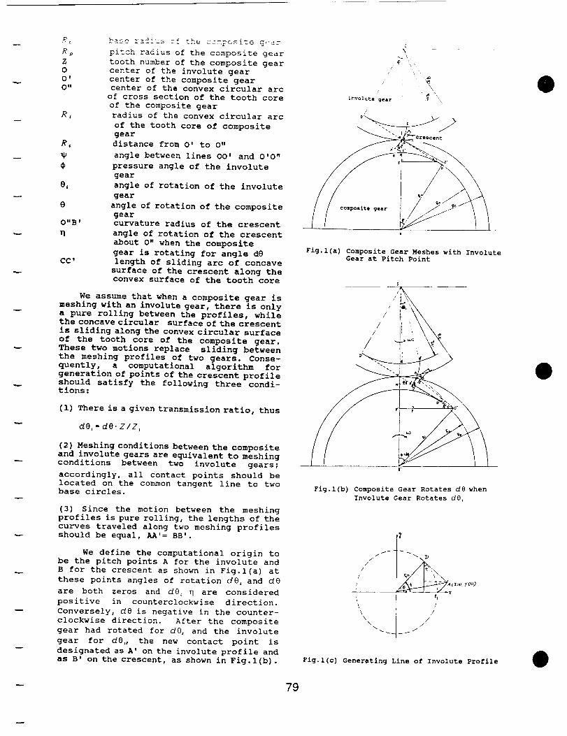
_t
Rp
Z
0
O'
O"
RL
Re
0
O" B f
n
CC '
base rzdius cf the ccm?osite gear
pitch radius of the composite gear
tooth number of the composite gear
center of the involute gear
center of the composite gear
center of the convex circular arc
of cross section of the tooth core
of the composite gear
radius of the convex circular arc
of the tooth core of composite
gear
distance from O' to O"
angle between lines OO' and O'O"
pressure angle of the involute
gear
angle of rotation of the involute
gear
angle of rotation of the composite
gear
curvature radius of the crescent
angle of rotation of the crescent
about O" when the composite
gear is rotating for angle d8
length of sliding arc of concave
surface of the crescent along the
convex surface of the tooth core
We assume that when a composite gear is
meshing with an involute gear, there is only
a pure rolling between the profiles, while
the concave circular surface of the crescent
is sliding along the convex circular surface
of the tooth core of the composite gear.
These two motions replace sliding between
the meshing profiles of two gears. Conse-
quently, a computational algorithm for
generation of points of the crescent profile
should satisfy the following three condi-tions:
(i) There is a given transmission ratio, thus
dO, = dO. Z/Z,
(2) Meshing conditions between the composite
and involute gears are equivalent to meshing
conditions between two involute gears;
accordingly, all contact points should be
located on the common tangent line to two
base circles.
(3) Since the motion between the meshing
profiles is pure rolling, the lengths of the
curves traveled along two meshing profiles
should be equal, AA'= BB'.
We define the computational origin to
be the pitch points A for the involute and
B for the crescent as shown in Fig.l(a) at
these points angles of rotation d0, and dO
are both zeros and dO, _ are considered
positive in counterclockwise direction.
Conversely, d8 is negative in the counter-
clockwise direction. After the composite
gear had rotated for dO, and the involute
gear for dO,, the new contact point is
designated as A' on the involute profile and
as B' on the crescent, as shown in Fig.l(b).
¢
/ i
\/
involute gear "_, \_''
/
Fig.l(a) Composite Gear Meshes with Involute
Gear at Pitch Point
0
/ li̧
0'
Fig.l(b) Composite Gear Rotates d8 when
Involute Gear Rotates dO,
//
/
/
/
/
\\\\
/
//
/
Fig.l(c) Generating Line of Involute Profile
- 79
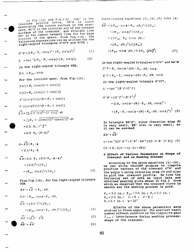
In Fig.l(a) and Fig.l(b), EAA' is the
involute profile curve, GB'B is curve
describing the convex surface of the cres-
cent, HC'C is the circular arc of the concave
surface of the crescent, and straight line
DD' is the common tangent line for two base
circles of the gears. From Fig.l(a), the
following expressions can be written for the
right-angled triangles O'O"F and O"FB :
I
O'B = [(Rp- R_" cos_) 2÷ (R_. sin_)2]_ (1)
k .tan'l[(Rp -R,'c0s_)l(R,'sin_)] (2)
In the right-angled triangle ODA,
DA . Rp,.. sine
For the
X(t)-R_
y(t)-Rb
x'(t)-d
y'(t)-cl
EA'f;_-[
t
-[oR,
involute gear, from Fig.l(c),
• [cos(t) + t" sin(t)]
• [sin(t)-t' cos(t)]
X (t)/dt- Rb' t" cos(t)
y (t)/dt- Rb " t" sin(t)
X.(t)] 2+[y'(t)] 2.at
• t. _/[ cos (t)'] 2÷ [sin(t)] =" at
- 0.5- Rb't 2 It'*
-0.5. R_. (0+¢) 2
s-%
O=ED/Rb-¢
= DA/Rb-#
EA = 0.5, Rb.(DA/Rb-¢+¢) 2
=(DA)2/(2Rb,)
= (Rp,.' sin¢)21(2Rb,) (3)
From Fig.l(b), for the right-angled triangle
ODA
AA' = EE'= Rb,'dO,
DA'=Rp,.'sln¢+R_,'d0,
EA'=(DA')Z/(2Rb,)
=(Rm..sinO+R_,'dO,)_/(2Rb,) (4)
AA.=IEA,_E_AI (5)
Substituting equations (3) , (4) , (5) into (6)
BB'- l(Rp,,, sin¢+Rb,.dO,)_/(2Rb,)
- (Rp,.. sin ¢)z/(2Rb,)l
= I[2R_,°' R_,. sin _. de,*
÷ (eb,' aO,)_]/(2Ro,)l
-IR sin ,. do, +o.5R,,-(ao)"I (7)
In the right-angled triangles O'O"F' andAA'M
O"F = R_. sin(_,÷ dO)- Rb," dO,. cos¢
B'F = Rp- R," cos(w ÷ dO)- Rb," dO," sine
In the right-angled triangle B' FO",
k' =tan-l(B'F/O "F)
i
O'B'=(O'F2+B'F2) '
= {[R:" sin(_ +dO) - Rb,"dO,' c0s_]2+
I_
+[Rp-R=.cos(_2+dO)-Rn .dO .sind_]2}" (8)
In triangle BB'O",
is very small, BB'
it can be assumed
.-%
BB' = BB'
since iteration step dO
also is very small, so
n=cos-I([O..B,2+O.,B2-BB,2]/[2,0"B'.O"B]) (9)
cc'- R,.[(k' + n)-(X *ore)]
2 Effect of Various Parameters on Shape of
Crescent and on Meshing Process
According to the above equations (i)-(9),
we can write CALCOMP program to compute
position vectors of the crescent O"B' and
the angle _ using iteration step dO and also
to plot the crescent profile. We took the
following set of data as input data and
obtained meshing plots shown in Fig.2 from
which we observed that the crescent curve is
smooth and the meshing process is good.
Rb,=3.0 in. ; Rp,,=3.5 in.; Rb-3.0 in. ;
Rp=3.5 in.; Z,-8 ; Z=8 ;
R=-3.1 in.; W=32 *
Effects of the above parameters were
studied in three aspects: The smallest teeth
number without undercut of the composite gear
Zm_. ; interference during meshing process;
shape of the crescent.
8O
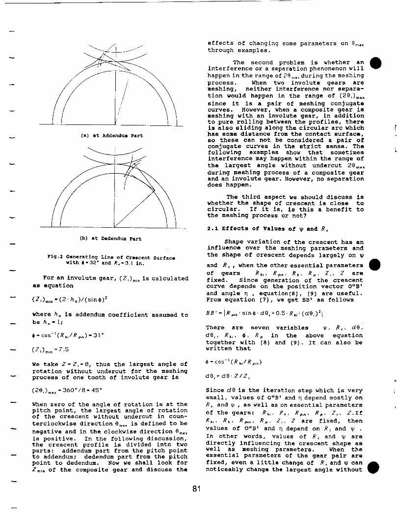
(a) at Addendum Part
(b) at Dedendum Part
Fig.2 Generating Line of Crescent Surface
with #-32" and R,-3 1 in.
For an involute gear, (Z,)m," is calculated
as equation
(Z,)=t .=(2 ho)/(sin¢)2
where ha is addendum coefficient assumed to
be ha-l;
¢ = cos-l(Rb,IRp,.) - 31 °
(Zt)mi n =7.5
We take Z-Za-8, thus the largest angle of
rotation without undercut for the meshing
process of one tooth of involute gear is
(2e,)_, =360o/8=45 °
When zero of the angle of rotation is at the
pitch point, the largest angle of rotation
of the crescent without undercut in coun-
terclockwise direction 8m. x is defined to be
negative and in the clockwise direction 8m. x
is positive. In the following discussion,
the crescent profile is divided into two
parts: addendum part from the pitch point
to addendum; dedendum part from the pitch
point to dedendum. Now we shall look for
Z_,. of the composite gear and discuss the
81
effects of changing some parameters on 8m. x
through examples.
The second problem is whether an
interference or a separation phenomenon will
happen in the range of 28m.×during the meshing
process. When two involute gears are
meshing, neither interference nor separa-
tion would happen in the range of (28,)m. x
since it is a pair of meshing conjugate
curves. However, when a composite gear is
meshing with an involute gear, in addition
to pure rolling between the profiles, there
is also sliding along the circular arc which
has some distance from the contact surface,
so these can not be considered a pair of
conjugate curves in the strict sense. The
following examples show that sometimes
interference may happen within the range of
the largest angle without undercut 28m. .
during meshing process of a composite gear
and an involute gear. However, no separation
does happen.
The third aspect we should discuss is
whether the shape of crescent is close to
circular. If it is, is this a benefit to
the meshing process or not?
2.1 Effects of Values of _ and R,
Shape variation of the crescent has an
influence over the meshing parameters and
the shape of crescent depends largely on
and Re, when the other essential parameters
of gears Rb,, R;,., Rb, Rp, Z,. Z are
fixed. Since generation of the crescent
curve depends on the position vector O"B'
and angle _ , equation(8), (9) are useful.
From equation (7), we get BB' as follows
BB' - [Rp,," sin ¢. dO,+ 0.5. Rb,' (dO,)_l
There are seven variables _, Re. dO,
dO_, Rb,, ¢, Rp in the above equation
together with (8) and (9). It can also bewritten that
¢ - cos -1 (Rb,/Rp,,_)
dO, = dO" Z/Z,
Since dO is the iteration step which is very
small, values of O"B' and q depend mostly on
Rc and _ , as well as on essential parameters
of the gears: Rb,, Rb. Rp,., Rp, Z_, Z.If
Rb,, Rb, Rp,., Rp, Z,, Z are fixed, then
values of O"B' and q depend on R: and _ .
In other words, values of Rc and _ are
directly influencing the crescent shape as
well as meshing parameters. When the
essential parameters of the gear pair are
fixed, even a little change of Rc and _ can
noticeably change the largest angle without
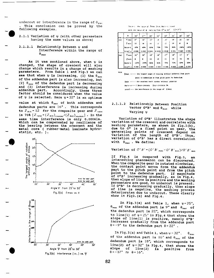
e
undercut or interference in the range of 0ma _
This conclusion can be proved by the
following examples.
2.1.1 Variation of _ (with other parameters
having the same values as above)
2.1.1.1 Relationship Between _ and
Interference within the range of
emax
As it was mentioned above, when _ is
changed, the shape of crescent will also
change which results in a change of meshing
parameters. From Table 1 and Fig.3 we can
see that when _ is increasing, (i) the em, x
of the addendum part is also increasing, but
(2) 8m. x of the dedendum part is decreasing
and (3) interference is increasing during
addendum part. Accordingly, these three
factor should be considered when the value
of _ is selected. Here _=32 ° is an optimum
value at which 8m,x of both addendum and
dedendum parts are 16 ° . This corresponds
to Z mm" ]2 for the composite gear and Z:=,o
is 70% [Zra,o=(Zm,n) ......./(Zmm),._o_u,,] . In the
same time interference is only 0.0006in.
Which can be compensated by resilience of
the bearing between the crescent and the
metal core ( rubber-metal laminate hydro-
static, etc. ).
x e0t-
cz:__:
g
.c_
UC
0
ID
J
y]l H for odd. port
• 3's' • _ • iv " so"Angle %J/ from 2,5' to ,50"
Fig,3(b) Interference ([fl.) vs. X_
7a_e-i _he ",IZue of _mtx. ZmLn. Ra_=_-z En_erf
frith the v|lue of
_ _ m_ _° _0 _
Interf_ _ 0 000 0 000
_d _ _ 2_ _ 22"
Z m_n 8 I
_t_o-_ _00% 100_
I_te_f _ 0O00 0 0OO
30" I 32" 33" 34' 40" 50"
]4" j _6' t6" _$" 22' 22"
14 [ t2 _2 tO 8 |
4
60_ [ 70_ 70_ $0_ 100% lO0_00001 0 0006 O.O00g 000_ 0003 0.00_
I_* iS' |7" I_* 11" 6 _
10 10 L[ 16 ]$ 32
85_ 8g_ 76% 70% SO_ 26%
0000 0 000 0000 0000 0000 0.000
_max ..... the lit|eft In|it of rotlting without undercut from pitch
point tp Idde_dum or from pitch point to dedendum
ZmJ_ ..... the sroallelt teeth _umb_r without _ndercut
Ritto-z-_- ( Zmkn-¢reseent ! Zm_n-l_vo[ute )_
I_terf--- the Interferlnce In t_e r=.ge of _ rt=x
2.1.1.2 Relationship Between Position
Vector O"B _ and Om_ x while
Varying
Variation of O"B' illustrates the shape
variation of the crescent and correlates with
meshing parameters, as shown in fig.l(b),
due to O" is a fixed point on gear, the
generating points of crescent depend on
variation of the length of O"B'. Thus,
variation of O"B' has a direct correlation
with 0m, x . We define:
Variation of O"B'=(O'B'm.x-O"B'm,n)/O'B'm,,
If Fig.4 is compared with Fig.3, an
interesting phenomenon can be discovered.
When the composite gear is rotated clockwise,
the contact point moves from the addendum
part to the pitch point and from the pitch
point to the dedendum part. If magnitude
of O"B' increasing gradually, as in Fig.4,
then slope of line is positive and the meshing
parameters are good, no undercut is present.
If O"B' is decreasing gradually, then slope
of line is negative, the meshing process
deteriorates due to undercut. These clearly
show in Fig3.(a) and Fig.4.
In Fig.3(a) and Table i, when _ =25 =,
Om, x of the addendum part is 9 ° and Om, _ of
the dedendum part is 22 °, which corresponds
to line(l) of _=25 ° in Fig.4 that shows the
slope of line(l) is positive, namely O"B'
increases gradually from the addendum part
0 = -9° to the dedendum part O = 22 °
In Fig.3(a) and Table I, when V = 32 ° . 0=. x
of the addendum part is lO ° and 0m. x of the
dedendum part is 18 °, which corresponds to
line(2) of _ =32 ° in Fig.4, that shows the
slope of line(2) is positive from
0=-17 ° to O= ]6 °.
82
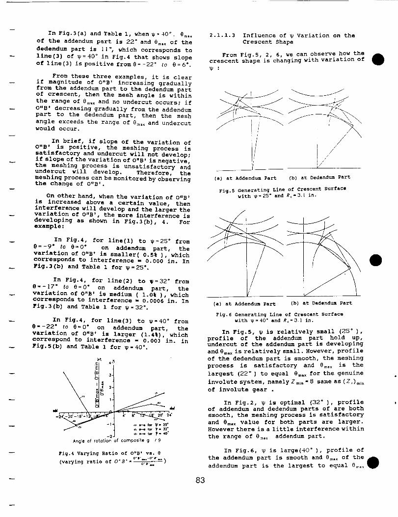
In Fig.3(a) andTable 1, when_=40 °, em,x
of the addendum part is 22 ° and Ore, x of the
dedendum part is 1 | ", which corresponds to
line(3) of _=40" in Fig.4 that shows slope
of line(3) is positive fromS=-22" to 8=6 ° .
From these three examples, it is clear
if magnitude of O"B' increasing gradually
from the addendum part to the dedendum part
of crescent, then the mesh angle is within
the range of em, x and no undercut occurs; if
O"B' decreasing gradually from the addendum
part to the dedendum part, then the mesh
angle exceeds the range of @max and undercut
would occur.
In brief, if slope of the variation of
O"B' is positive, the meshing process is
satisfactory and undercut will not develop;
if slope of the variation of O"B' is negative,
the meshing process is unsatisfactory and
undercut will develop. Therefore, the
meshing process can be monitored by observing
the change of O"B'.
On other hand, when the variation of O"B'
is increased above a certain value, then
interference will develop and the larger the
variation of O"B', the more interference is
developing as shown in Fig.3(b), 4. For
example:
In Fig.4, for line(l) to _=25 ° from
8 = -9 ° to e = 0 ° on addendum part, the
variation of O"B' is smaller( 0.5% ), which
corresponds to interference = 0.000 in. In
Fig.3(b) and Table 1 for _=25".
In Flg.4, for line(2) to _=32" from
e = -]7" to e = 0 ° on addendum part, the
variation of O"B' is medium ( 1.0% ), which
corresponds to interference = 0.0006 in. In
Fig.3(b) and Table 1 for _=32".
In Fig.4, for line(3) to _=40 ° from
8--22" to 8 = 0 ° on addendum part, the
variation of O"B' is larger (1.4%), which
correspond to interference - 0.003 in. in
Fig.5(b) and Table 1 for _=40 °.
c_'_ 47.
\
/"'" _ ., .-* fo, _r- 32.j _, ._.. ,0, _.4o
Angle of fore,ion of compositLe g r @
Fig.4 Varying Ratio of O"B' vs. e
°" I'mu'°" I'm"(varying ratio of 0"8" o-r...
2.1.i.3 Influence of _2 Variation on the
Crescent Shape
From Fig.5, 2, 6, we can observe how the
crescent shape is changing with variation of
:
/J
I__L(a) at Addendum Part
//
/I //
/
(b) at Dedendum Part
Fig.5 Generating Line of Crescent Surface
with _ =25" and Rc-3.[ in.
(a) at Addendum Part (b) at Dedendum Part
Fig. 6 Generating Line of Crescent Surface
with _=40 ° and R_-3 I in.
In Fig.5, _P is relatively small (25 = ),
profile of the addendum part hold up,
undercut of the addendum part is developing
and Bm.x is relatively small. However, profile
of the dedendum part is smooth, the meshing
process is satisfactory and 8m.x is the
largest (22 ° ) to equal era,X for the genuine
involute system, namely Zm.,- 8 same as (Z,)mi .
of involute gear .
In Fig.2, _u is optimal (32 ° ), profile
of addendum and dedendum parts of are both
smooth, the meshing process is satisfactory
and 8m.x value for both parts are larger.
However there is a little interference within
the range of em,x addendum part.
In Fig.6, _ is large(40 ° ), profile of
the addendum part is smooth and 8m.x of the
addendum part is the largest to equal 8_.x
83
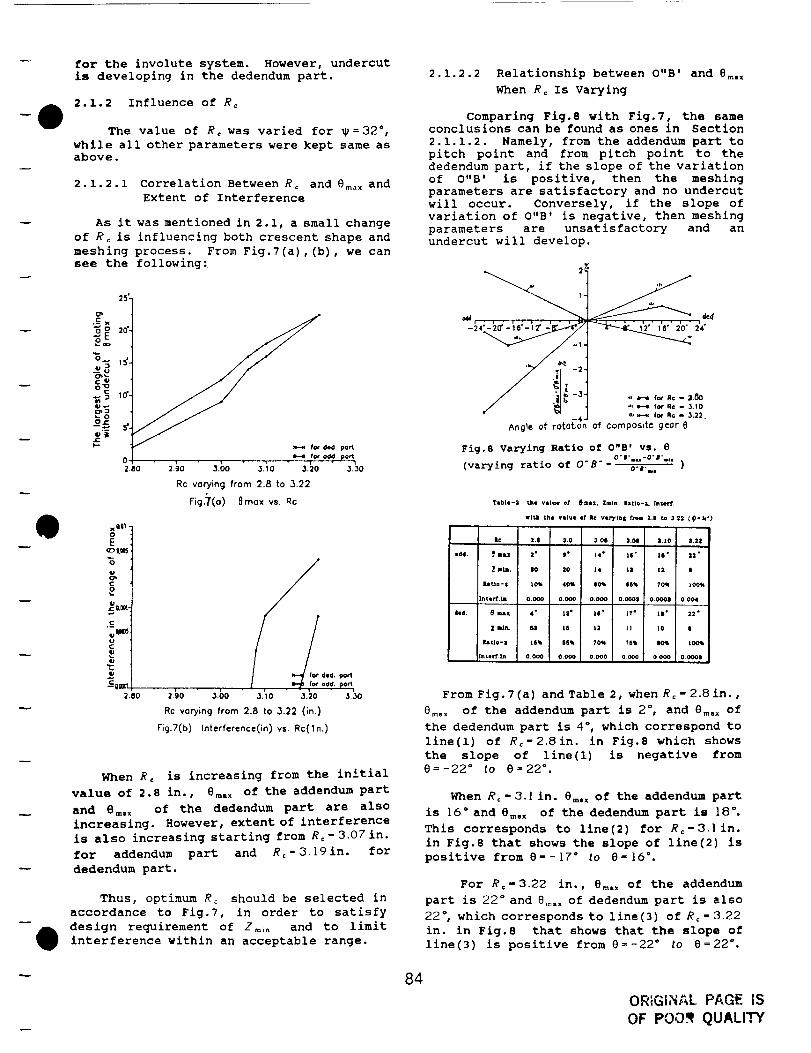
for the involute system. However, undercut
is developing in the dedendum part.
2.1.2 Influence of R¢
The value of Rc was varied for _ = 32",while all other parameters were kept same as
above.
2.1.2.1 Correlation Between Rc and 8ma x and
Extent of Interference
As it was mentioned in 2.1, a small change
of Re is influencing both crescent shape and
meshing process. From Fig.7(a), (b), we can
see the following:
25"
.-¢ x
ce
o7N= _o'-
_m=O
o= 5"-
0
2,80
fo¢ ded. part
• H ,r_ od.d.port2._o " 3.5o " ",.;o 3.20 _._o
Rc vorying from 2.8 to 3.22
rig.7(o) 8mox vs. Rc
xO|l -
8
._,u111m_u¢
,i,i
-came2.80
for did, po_
2._o 3._)o ' ._.Io 3.=0 3/,0Rc varying from 2.8 to 3.22 (in.)
Fig.7(b ) Interference(in) vs. Rc(ln.)
When Re is increasing from the initial
value of 2.8 in., 8m. x of the addendum part
and 8m, x of the dedendum part are also
increasing. However, extent of interference
is also increasing starting from Rc=3.07in.
for addendum part and Re- 3.[9 in. for
dedendum part.
Thus, optimum R_ should be selected in
accordance to Fig.7, in order to satisfy
design requirement of Z_L, and to limit
interference within an acceptable range.
2.1.2.2 Relationship between O"B' and 8m, x
When Rc Is Varying
Comparing Fig.8 with Fig.7, the same
conclusions can be found as ones in Section
2.1.1.2. Namely, from the addendum part to
pitch point and from pitch point to the
dedendum part, if the slope of the variation
of O"B' is positive, then the meshing
parameters are satisfactory and no undercut
will occur. Conversely, if the slope of
variation of O"B' is negative, then meshing
parameters are unsatisfactory and an
undercut will develop.
-4-
Angle of" rotation of composite geor 0
Fig.8 Varying Ratio of O"B' vs. OO" m' =u- O" #'.,,.
(varying ratio of 0"8"= 0"#'_.
edd.
ded.
T&bie-3 the vll',,*e ot _mlz, Zla/n. bile-C, ht_l.r1".
wlth the value Of Rc vlWIo | fr.ll 2.I '4:, 3.22 (_)*N')
I¢ 2.1 3.0 3.06 I.Sll l.lO 3.22
4 IIIx _" I" 14" l&" 14" 23 "
Z Bin. 80 20 14 _$ t;I $
htlo-$ 101_ 40qL ISO_ 1611 ?016 JO0_
Intert.ln 0.000 0.000 0.000 0.0005 0.000| 0,004
_1 leaJ_ 4" 12" 14" 17_ 11" 22"
Z Idn. Ikl IE 12 l I I0 l
bUO-Z 18q_ $6ql 70_ ?6qt 80qL |O01k
[nterf.Ln 0.000 0.000 0.000 0000 OOOO i O.O00e
From Fig.7(a) and Table 2, when R_-2.8in.,
Om. × of the addendum part is 2 °, and Om, x of
the dedendum part is 4 °, which correspond to
line(l) of Rc-2.Sin. in Fig.8 which shows
the slope of line(l) is negative from
8=-22 ° to B=22 ° .
When R_-3.I in. 8m. x of the addendum part
is 16 ° and O=o x of the dedendum part is 18 °.
This corresponds to llne(2) for Rc-3.lin.
in Fig.8 that shows the slope of line(2) is
positive from 8 =-17 ° to 8 = 16".
For R c-3.22 in., 8m. x of the addendum
part is 22 ° and Oma x of dedendumpart is also
22 °, which corresponds to line(3) of Rc-3.22
in. in Fig.8 that shows that the slope of
line(3) is positive from 0=-22 - to 8 = 22".
84
ORIGINAL PAGE IS
OF POOR QUALITY
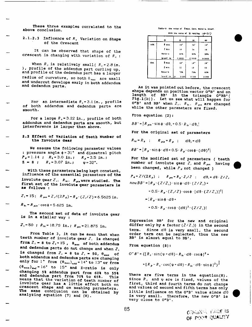
These three examples correlated to theabove conclusion.
Tlbie'3 _he vslue of _msx. Zml., Ratio-z. In¢orY.
wl_h ,.he vll.e or 7.1 vlrYt.I _-)1')
2.1.2.3 Influence of Rc Variation on Shape
of the Crescent
It can be observed that shape of the
crescent is changing with variation of R_ :
When Rc is relatively small( R: _2.8in.
), profile of the addendum part curling up,and profile of the dedendumpart has a larger
radius of curvature, so both 8m. x are small
and undercut develops early in both addendumand dedendum parts.
For
of both
smooth.
an intermediate Re-3.1 in., profile
addendum and dedendum parts are
For a large Rc-3.22 in., profile of both
addendum and dedendumparts are smooth, but
interference is larger than above.
2.2 Effect of variation of Teeth Number of
the Involute Gear
We assume the following parameter values
: pressure angle #=31 ° and diametral pitch
Pc" 1.1% ; Rb-3.O in.; Rp-3.5 in.;
Z - 8 ; R_-3.07 in.; _=32 °.
With these parameters being kept constant,Influence of the essential parameters of the
involute gearI,, Rb,. R_,were studied. The
first set of the involute gear parameters isas follows :
Z_- 15; Rp_.-ZJ(2Pd)-R_.(Z,/Z)-6.5625in.
Rb, " Rp,," cos# = 5.625 in.
sdd.
4o4.
ZI | 14 $0
mla 14" 14" 13"
I rB_n 14 14 16
Itstlo-z eO% 60_ SSql
lntlrf _n 0 0C03 0.0003 00003
mL_ l_" L6 ° 16'
l enin 12 12 13
Illtlo- Z _0_ ?0_ 88qI
In[err In In 00CO 0 000 0 000
As it was pointed out before, the crescentshape depends on position vector O"B' and on
length of BB ' in the triangle O"BB ' (Fig.l(b)). Let us see what will happen for
O"B' and BB' when Z,, Rb,. Rp,, are changed
while the other parameters are fixed.
From equation (2) :
BB' : IRp,," sin_- d0,+ 05. Rb,. dO,I
For the original set of parameters
Rbi=Rb ; Rp,.=Rp ; dOL:d8
BB' = [Rp' sin#. de+ 0.5" Rp" cos_' (dO)zl
For the modified set of parameters ( teeth
number of involute gear Z, and Rp,, having
been changed, while Pd not changed )
P4"Z/(2Rp) ; Rp,.'Rp'Z,/Z ; dO,-de.Z/Z,
neu.,BB' = IRp" (Z/Z,)" sin _. de. (Z/Z,) +
+0.5. Rp. (Z,/Z). ¢os_. [de. (z/z,)]zl
- IRp" sin_. de+
*0.5. Rp. cos_. (de)" (Z/Z,)I
The second set of data of involute gearis in a similar way :
I_-50 t Rb,-18.75 in.; Rp,,-21 875 in.
From Table 3, it can be seen that when
teeth number of involute gear Z_ is changed
from Z,- 8 to Zi- t5 , 8_,x of both addendum
and dedendumparts do not change and when Z_
is changed from Z_ - 8 to Z_ - 50, %m.x of
both addendum and dedendumparts are changing
only for I ° from (e_._)o_-14" to 13 ° or from
(6_o.)_-16 ° to I_ ° and Z-ratio is only
changing 5% addendum part from 60% to 55%and dedendum part from 70% to 65%. Thismeans that the variation of teeth number of
involute gear has a little effect both oncrescent shape and on meshing parameters.The same concluslon can be obtained by
analyzing equation (7) and (8).
Expression BB' for the new and original
differ only by a factor (Z/Z,)) in the second
term. Since d8 is very small, the second
order term can be neglected, thus the new
BB' is almost equal to BB'.
From equation (8) :
O"B' = {[R_" sin(_+de)- R_," de. cos#]'+
+[R_-R¢'c0s(_+de)-R_, de.sin#]Z} '
There are five terms in the equation(8).
Since Re and _ are is fixed, values of the
first, third and fourth terms do not changeand values of second and fifth terms has only
little influence on the O"B' value since dO
is very small. Therefore, the new O"B' is
very close to O"B'.
85
Oi:
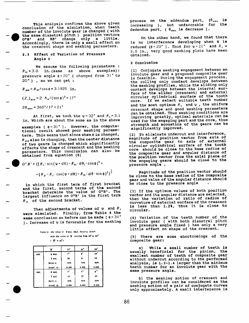
This analysis confirms the above given
conclusion of the simulation, when teeth
number of the involute gear is changed ( with
the same diametral pitch ) position vectors
O"B' and BB' change only a little.
Accordingly, there is only a small effect on
the crescent shape and meshing parameters.
2.3 Effect of Variation of Pressure
Angle $
We assume the following parameters :
Rb,-30 in.(same as above examples);
pressure angle $=20 ° ( changed from 31 ° to
20 ° ) , so we can get :
Rp_-Rb_/cos_-3.1925 in.
(Z,)m_ . = 2" ho/(sin$) TM 17 °
28mo. = 360°/17=21 °
At first, we took the _ = 32 ° and Re-3.[
in. Which are about the same as in the above
examples ( _=3| ° ). However, the computa-
tional result showed poor meshing parame-
ters. This means that since when $ is changed,
R,,, also is changing, then the center distance
of two gears is changed which significantly
effects the shape of crescent and the meshing
parameters. This conclusion can also be
obtained from equation (8)
O" 8' = {[ Re" sin (_ + de) - Rb," de,. cos$] 2 +
I
÷ [Rp - Re" cos(_ + de)- R.__de. sin $]z}}
in which the first term of first bracket
and the first, second terms of the second
bracket determine the value of O"B'. The
largest influence on O"B' is the first term
R, of the second bracket.
Then adjustments of values of _ and Rc
were simulated. Finally, from Table 4 the
same conclusion as before can be made ($=3[ °
). Increase of _ is favorable for the meshing
T&b|e-4 the va|ut ot _ max. 7J;un, Ratio-t. L_tel-f.
wlta the vsl_e or _ var)'ln$ _,m 2f' to 28"
(_) =30")
_dd.
ded.
process on the addendum part, _Sm. x is
increasing ), but unfavorable for the
dedendum part, ( 8m, x is decrease ).
On the other hand, we found that there
is no interference developing when $ is
reduced ($=20 ° ). Thus for _=2| ° and Rc =
3.0 in., very good meshing plots have been
obtained.
3 Conclusion
(i) Conjugate meshing engagement between an
involute gear and a proposed composite gear
is feasible. During the engagement process,
the rolling only contact develops between
the meshing profiles, while the sliding only
contact develops between the internal sur-
face of the slider (crescent) and external
circular cylindrical surface of the tooth
core. If we select suitable teeth number
and the most optimum R c and _ , the uniform
crescent shape and good meshing parameters
can be obtained. Thus meshing conditions are
improving greatly, optimal materials can be
used for the engaging part and the core, thus
strength and acoustics of the gears can be
significantly improved.
(2) To eliminate undercut and interference,
magnitude of position vector from axis of
the composite gear to axis of external
circular cylindrical surface of the toothcore should be close to the base radius of
the composite gear and angular distance of
the position vector from the axial plane of
the engaging gears should be close to the
pressure angle .
Magnitude of the position vector should
be close to the base radius of the composite
gear and value of the angular distance should
be close to the pressure angle
(3) If the optimum values of both position
vector and its angular distance are selected,
then the variation of ratio of radius of
curvature of external surface of the crescent
is less than 1.2%, thus it is close to
circular.
(4) Variation of the teeth number of the
involute gear ( with both diametral pitch
and pressure angle fixed ) has only a very
little effect on shape of the crescent.
(5) There are some shortcomings of the
composite gear:
a) While a small number of teeth is
usually beneficial for the pinion, the
smallest number of teeth of composite gear
without undercut according to the performed
analysis, is 1.3-1.4 larger than the minimum
teeth number for an involute gear with the
same pressure angle.
b) The meshing motion of crescent and
involute profiles can be considered as the
meshing motion of a pair of conjugate curves
only approximately. A small interference is
86
always developing. Variation of pressure
angle or center distance of two gears is
slightly influencing meshing parameters.
However, these factors are not expected to
be a limitation of the suggested gear system
since a small influence would be compensated
by compliance in the joint between the
crescent and the tooth core.
(6) The proposed and investigated gear system
is promising for plastic gears since a unit
crescent-elastic connection-tooth core can
be extruded. Load-carrying capacity of
plastic gears would be substantially
enhanced if a pure rolling develops between
the meshing profiles.
Reference
I. R. E. Denning and S.L.Rice, " Surface
Fatigue Research with the Geared Roller Test
Machine " SAE Automotive Engineering
Congress Jan.14-16 1963.
2. E.I.Rivin and Rui-Ning Wu, "A Novel
Concept of Power Transmission Gear Design ",
SAE Technical Paper Series 871646, SAE 1987.
3. E.I.Rivin, "Properties and Prospective
Applications of Ultra Thin Layered Rubber-
Metal Laminates for Limited Travel Bear-
ings", Tribology International, Volume 16
Number 1 February 1983.
4. E.I.Rivln, " Conjugate Gear System ", U.S.
Patent Application.
87