Embed Size (px)
Citation preview

Wireless chipless passive electromagnetic transducers for
SHM applications
Patrick Pons, Herve Aubert, Manos Tentzeris
To cite this version:
Patrick Pons, Herve Aubert, Manos Tentzeris. Wireless chipless passive electromagnetic trans-ducers for SHM applications. International Worshop on SHM (IWSHM), Sep 2013, Standford,United States. Proceedings IWSHM 2013 (Proceedings IWSHM 2013), 8 p., 2013. <hal-01053192>
HAL Id: hal-01053192
https://hal.archives-ouvertes.fr/hal-01053192
Submitted on 29 Jul 2014
HAL is a multi-disciplinary open accessarchive for the deposit and dissemination of sci-entific research documents, whether they are pub-lished or not. The documents may come fromteaching and research institutions in France orabroad, or from public or private research centers.
L’archive ouverte pluridisciplinaire HAL, estdestinee au depot et a la diffusion de documentsscientifiques de niveau recherche, publies ou non,emanant des etablissements d’enseignement et derecherche francais ou etrangers, des laboratoirespublics ou prives.

Wireless chipless passive electromagnetic transducers for SHM applications
a,b
Patrick PONS, a,b
Hervé AUBERT, c Manos TENTZERIS
a CNRS, LAAS, 7 avenue du colonel Roche, F-31400 Toulouse, France
b Univ de Toulouse, LAAS, F-31400 Toulouse, France
c School of ECE, Georgia Institute of Technology, Atlanta, GA 30332, U.S.A
ABSTRACT
The energy autonomy of wireless sensors is crucial especially for buried or inaccessible sensors that
are often the case in SHM applications. This problem can be overcome by using classical passive sensors
(RFID or SAW sensors) but they suffer from a problem of low reading distances (<10m). For few years
emerged a new kind of passive sensors using electromagnetic transducers, combining very high autonomy,
high resistance to harsh environment, potential interrogation distance higher than SAW sensors and wide
variety of sensing principles. We started to work in this new research field in 2005 and several sensor
principles have been validated in our lab (pressure, temperature, stress) with FMCW (Frequency
Modulated Continuous Wave) Radar interrogation.
INTRODUCTION
Since the late 1990s, wireless sensor networks emerge as a key technology for numerous
applications (domestic, health, environmental, industrial, military, ...)
[1-4] and especially for Structural Health Monitoring (SHM) [5-8]. One can divided wireless sensors
technologies into two main classes: (1) active sensors which require RF transmitter and (2) passive
sensors without RF transmitter.
Active sensors can be described by three different functional parts: a transducer which converts the input
to be analyzed into electrical signal, electronic circuits for the signal conditioning and a communication
unit for data transmission (Figure 1). This type of sensors works generally with a battery related to the high
consumption of the transmitter. The main advantages of this kind of sensors are : a high reading distance
(up to several km), a high fickleness with the possibility to use any kind of transducers, an easy
identification compatible with large sensors network and a low sensitivity to electromagnetic interferences.
The key limiting factor is the sensor autonomy and the sensor life time is driven by embedded quantity of
energy (mainly the battery size), the data transmission rate and the reading distance. Another drawback is
the low resistance to harsh environments (high temperature, high radiation level) related to the presence of
electronic circuits. Then, despite the disadvantages of this type of active sensors, a lot of companies
propose now wireless active sensor products that are suitable for different applications. That was made
possible by the availability on the market of low cost and efficient (low consumption, low size)
transducers, electronic circuits (from DC to RF) and batteries but also the availability of standardized
transmission protocol (e.g., Wifi, Zigbee and Bluetooth). The main research studies in this field for
increasing the sensor autonomy are concentrated on the development of new energy micro-source with
high power (electrochemical, nuclear, thermo-electric, thermo-ionic, …), high efficiency of energy
harvesting (solar, vibration, thermoelectric, Radio-Frequency, …) and low consumption electronic circuits.

Input to be
analyzedTransducer
Analog electrical
signal
Analog signal
conditioning
Digital electrical
signal
Data
transmission
Analog-Digita l
Converter
RF
Transmitter
Battery
Figure 1. Synoptic of active wireless sensor
Passive sensors is typically composed of two parts: (1) a passive transducer with only passive
elements and (2) a remote reader able to analyze the transducer response (Figure 2). The wireless
communication between these two parts can exploit electrical, magnetic, electromagnetic, acoustic or
optical link. The most popular are magnetic and electromagnetic links, related to the availability of several
low costs solutions for electronic readers. The first one called “near field communication” is quite old and
is limited by the very short reading distance (few tens of cm). Electromagnetic interrogation, based on the
analysis of backscatter wave by the transducer, allows overcoming this limitation. Two classes of passive
sensors with electromagnetic interrogation already exist on the market : RFID and SAW.
ReaderInput to be
analyzedTransducer
Figure 2. Synoptic of passive wireless sensor.
RFID passive sensors are based on the modulation of the backscatter wave level between two states
(RCS1 and RCS2) reproducing digital coding of the signal
(Figure 3). This modulation is obtained through the switching between two different loads connected to
the antenna. The switch is driven by the digital output of a microcontroller that converts the analog
response of the transducer. The main advantage, compared with active sensors, is the very high autonomy
since the RF transmitter is removed and all the electronic units are powered through RF link. In return, the
reading distance is generally lower than 5m.
Z1
Antenna
Z2
Transducer
Microcontroller
0 , 1
RCS1 / RCS2
Analog Output
Digital Output
Figure 3. Synoptic of typical RFID wireless sensor
SAW sensors are based on piezoelectric substrate on which inter-digital electrodes (connected to an
antenna) allow converting the electromagnetic waves into acoustic waves (for the input signal) and
acoustic waves into electromagnetic waves (for the output signal). The backscattered signal is then

analyzed in time or frequency domain to extract transducer information as the propagation speed of the
acoustic wave in the piezoelectric material is dependent on several factors (stress, temperature, surface
coating, ....). The two main advantages compared to RFID passive sensors are the fully autonomous nature
of these sensors (no need of energy for electronic or transducer part) and the high resistance to harsh
environments. In return, the sensor response is fully analog making the identification more difficult and
reducing the accuracy. Moreover the sensing principles are restricted by the use of piezoelectric substrates.
Even if the reading distance is generally greater than that obtained for RFID sensors, this one is usually
lower than 10m, related to the low efficiency of the coupling coefficient between electromagnetic and
acoustic waves (between 0.1% and 5%).
Two main antagonistic requirements for SHM applications, i.e., a very high energy autonomy (for
buried or low accessibility sensors) and a high reading distances (>10m), are then often difficult to obtain
with the above-described sensors. Recently a new class of passive wireless sensors emerged based on the
electromagnetic transduction principle. These sensors are mainly composed of a variable RF impedance or
RF resonator connected to an antenna that can be interrogated through backscattered wave analysis [9-14].
These sensors combine the advantages of SAW sensors (fully autonomous, high resistance to harsh
environment) with an interrogation distance higher than 10m thanks to the elimination of the
electromagnetic/acoustic conversions. Another advantages of electromagnetic transducers compared to
SAW consists of using millimeter-wave frequency that allows the realization of efficient antennas (lower
size and higher directivity), the wide range of sensing properties through the large possibilities of sensing
principles (variation of physical or electrical length of the RF transducer, modification of the material
properties, modulation of RF coupling between the RF transducer and movable mechanical or fluidic
parts) and the possibility to use of great choice of materials.
Wireless passive and chipless electromagnetic transducers are then an interesting solution for several SHM
applications. We started to work in this new research field in 2005 and several sensor principles have been
validated in our lab (pressure, temperature, stress) with FMCW (Frequency Modulated Continuous Wave)
Radar interrogation.
PRESSURE SENSOR
We started this study in 2005 and the details on this sensor can be found in [15]. This device is
composed of a planar half-wavelength resonator (designed around 30GHz) deposited inside a circular
Pyrex cavity and a high resistivity silicon membrane anodic-bonded to Pyrex (Figure 4). The initial
distance between the resonator and the membrane is around few microns allowing the electromagnetic
coupling between the resonant mode in the planar resonator and the transverse stationary waves in the
dielectric membrane through the evanescent transverse EM field in the air slab. A weak membrane
deflection under pressure leads to the strong variation of the EM coupling and then gives a high resonant
frequency shift (~1GHz/µm between 0.25μm and 6μm). The sensor has been fabricated using classical
micro-technology process and characterized with a specific pressure probe module allowing on wafer S21
parameters. The sensor exhibits a very high sensitivity close to 0.37GHz/bar (up to 3 bars) for a 45µm
thick silicon membrane.

Figure 4. Topology of pressure sensor [15]
TEMPERATURE MEMS SENSOR
We started this study in 2009 in collaboration with Georgia Institute of Technology and more details
are given in [16]. The temperature transducer consists of split ring resonators (around 4.7 GHz) fabricated
on top side of substrate and excited by a coplanar transmission line located on wafer back side (Figure 5).
The slits of the rings are covered with bimorph micro-cantilevers whose layers are made from two
different materials. A temperature shift induces the cantilever deflection and then a modification of the
coupling capacitance between the two arms of the ring, which leads to the change of the resonant
frequency.
The rings and the coplanar line are deposited on a 787µm-thick Neltec substrate. The bilayers cantilever is
obtained by the lamination of a 100µm thick aluminum sheet and a 50µm thick polyethylene (PET) sheet.
Measurements of S11 parameter at two different temperatures (32°C and 60°C) show a relative resonant
frequency shift around 530ppm/°C and an estimated full scale variation close to 10%.
rint = 2.5mm, c = 1mm,
d = 0.5mm, s = 1mm
MEMS cantilever

Figure 5. Topology of temperature MEMS sensor [16]
TEMPERATURE FLUIDIC SENSOR
We started this study in 2010 in collaboration with Georgia Institute of Technology and more details
are given in [17-18]. The sensors are based on the thermal expansion of a fluid inside a polymer (SU8)
micro-channel fabricated above a RF structure. The principle has been validated first with a metallic liquid
by using an array of dipole antennas (Figure 6). A drastically step-by-step change of the Radar Cross
Section (RCS) of the sensor is obtained by short-circuiting progressively the two arms of the different
dipoles array. Devices operating around 30GHz were fabricated on Kapton with an array of 5 dipoles for
which short circuits were achieved by depositing Galinstan drop between the dipole strands. RCS
characterizations, performed using a millimeter-wave FMCW RADAR, have shown that one can obtain a
RCS shift close to 12dBsm for the full scale. Temperature sensor principle has been also validated using
dielectric fluid (water) that changes the permittivity between the two electrodes of a planar capacitor
(Figure 7). The capacitor length is equal to 400μm and provides a variation of the reflection coefficient
(S11) around 9 dB at 30 GHz for full scale. Capacitance then varies continuously from 20fF to 140fF
corresponding to temperature change of 9°C.
Metal
Tank with metal liquid
V 1mm3
Micro channel
S = 100µm x 100µm
Galinstan ( = 115ppm/ C)
Lc 12µm/ C
Figure 6. Topology of temperature fluidic sensor with metallic fluid [17-18]
Glass
100µm400 µm
525µm
880µm
SU-8 Microfluidic
structure
Distilled water
Planar
gap-capacitor
CPW
(RF probes)
Glass
170 µm
Figure 7. Topology of temperature fluidic sensor with dielectric fluid [17-18]

STRESS SENSOR
We started this study in 2010 in collaboration with Georgia Institute of Technology and more details
are given in [19]. The sensor is based on two coupled planar resonators (a patch antenna and an open loop)
whose resonant frequencies are close to 2.4 GHz. The loop is closed by a variable capacitor which changes
with the deformation (Figure 8). This variable capacitor is formed by a metal cantilever and the free metal
of the loop, separated by an insulator of 15μm thick. Deformation of the support (100 microns thick
Kapton) then causes a displacement of the anchor point of the cantilever. The surface of the capacitor is
then modified with sensitivity dependent on the length of the cantilever. The total size of the sensor is
40mm x 25mm. Simulation results show a maximum sensitivity of 4.5ppm/μ. Demonstrators were
manufactured with conventional technologies to fabricate the resonators and the cantilever. Then the
assembly was performed more or less manually which failed to achieve accurate positioning of the
cantilever. However a measured sensitivity of 1.3ppm/μ was obtained, that is as large as what has been
published to date.
Figure 8. Topology of stress sensor [19]
RADAR INTERROGATION
The interrogation system is based on the FMCW (Frequency Modulated Continuous Wave) Radar.
From the measured Radar Cross Section (electromagnetic echo) of the sensors, the physical quantity can
be wirelessly derived and the identification of the sensor can also be performed [20-21]. A Radar operating
at around 29.45 GHz has been designed and fabricated. The interrogation principle up to 30m has been
first validated using 1 cm2 passive target and few mW for Radar emission. In most cases of sensors
described previously, one transducer port is connected to an antenna through a coaxial cable (1m long) and
the second port of the transducer is connected to a 50 load. The RF cable which operates as a delay line
allows separating the transducer echo from the antenna echo. The beat frequency level, which corresponds
to the Radar output, is then modulated by the input to be analyzed (pressure, stress, temperature). A full
scale variation of the beat frequency level around 5 dB is generally obtained with the different transducers
and the sensor accuracy is estimated to 5% (Figure 9).

Figure 9. Example of Radar response with the pressure transducer
CONCLUSIONS
The principle of new passive sensors, based on electromagnetic transduction, has been validated for
several physical parameters (pressure, temperature, stress) which are interesting for SHM applications.
The main advantages of this new kind of sensors are: a very simple transducer part without battery and
without embedded electronic circuits and a wireless reading distance greater than 10m using a FMCW
Radar.
Nevertheless our main objective now is focused on the realization of sensors with given specifications
(sensitivity, accuracy, …) for specific applications.
ACKNOWLEDGEMENTS
Part of this work is supported by the French Project of ‘Pôle de compétivité’ entitled ‘Système
Autonome Communicant En Réseau’ (SACER). All these studies have been performed with PhD students
(Mehdi JATLAOUI, Franck CHEBILA, Thai TRANG, Sofiène BOUAZIZ, Anya TRAILLE).
REFERENCES
1. L Atzori, A Iera, G Morabito. The Internet of Things: A survey. Computer Networks 54 (2010), 2787-2805
2. L Ruiz-Garcia, L Lunadei, P Barreiro, J Robla. A Review of Wireless Sensor Technologies and Applications in Agriculture
and Food Industry. Sensors 2009, 9, 4728-4750
3. E Sardini, M Serpelloni. Passive and Self-Powered Autonomous Sensors for Remote Measurements. Sensors 2009, 9, 943-
960
4. H Alemdar, C Ersoy. Wireless sensor networks for healthcare, A survey. Computer Networks 54 (2010) 2688–2710
5. E.J. Brandon, et al., Structural health management technologies for inflatable / deployable structures: Integrating sensing
and self-healing, Acta Astronautica (2010),doi:10.1016/j.actaastro.2010.08.016
6. A. S. Kiremidjian, Structural Health Monitoring for Civil Infrastructure : From Instrumentation to Decision Support, IWSH
2011, Sept 13-15, Stanford University, USA
7. Chih-Yuan Chang, San-Shan Hung, Implementing RFIC and sensor technology to measure temperature and humidity inside
concrete structures, Construction and Building Materials (2011), doi:10.1016 /j.conbuildmat.2011.06.066
8. M.J. Chae, H.S. Yoo, J.Y. Kim, M.Y. Cho, Development of a wireless sensor network system for suspension bridge health
monitoring, Autom. Constr. (2011), doi:10.1016/j.autcon.2011.06.008
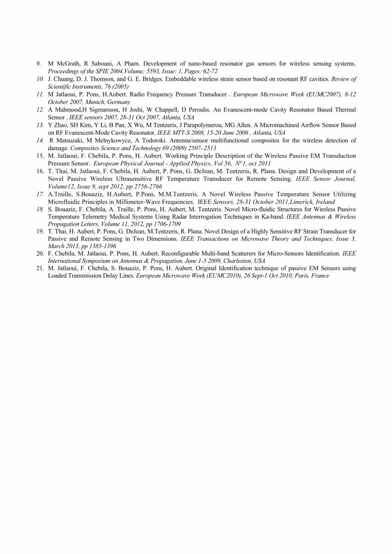
9. M McGrath, R Sabouni, A Pham. Development of nano-based resonator gas sensors for wireless sensing systems.
Proceedings of the SPIE 2004,Volume: 5593, Issue: 1, Pages: 62-72
10. J. Chuang, D. J. Thomson, and G. E. Bridges. Embeddable wireless strain sensor based on resonant RF cavities. Review of
Scientific Instruments, 76 (2005)
11. M Jatlaoui, P. Pons, H.Aubert. Radio Frequency Pressure Transducer . European Microwave Week (EUMC2007), 8-12
October 2007, Munich, Germany
12. A Mahmood,H Sigmarsson, H Joshi, W Chappell, D Peroulis. An Evanescent-mode Cavity Resonator Based Thermal
Sensor . IEEE sensors 2007, 28-31 Oct 2007, Atlanta, USA
13. Y Zhao, SH Kim, Y Li, B Pan, X Wu, M Tentzeris, J Parapolymerou, MG Allen. A Micromachined Airflow Sensor Based
on RF Evanescent-Mode Cavity Resonator. IEEE MTT-S 2008, 15-20 June 2008 , Atlanta, USA
14. R Matsuzaki, M Melnykowycz, A Todoroki. Antenna/sensor multifunctional composites for the wireless detection of
damage. Composites Science and Technology 69 (2009) 2507–2513
15. M. Jatlaoui, F. Chebila, P. Pons, H. Aubert. Working Principle Description of the Wireless Passive EM Transduction
Pressure Sensor. European Physical Journal - Applied Physics, Vol 56, N°1, oct 2011
16. T. Thai, M. Jatlaoui, F. Chebila, H. Aubert, P. Pons, G. DeJean, M. Tentzeris, R. Plana. Design and Development of a
Novel Passive Wireless Ultrasensitive RF Temperature Transducer for Remote Sensing. IEEE Sensor Journal,
Volume12, Issue 9, sept 2012, pp 2756-2766
17. A.Traille, S.Bouaziz, H.Aubert, P.Pons, M.M.Tentzeris. A Novel Wireless Passive Temperature Sensor Utilizing
Microfluidic Principles in Millimeter-Wave Frequencies. IEEE Sensors, 28-31 October 2011,Limerick, Ireland
18. S. Bouaziz, F. Chebila, A. Traille, P. Pons, H. Aubert, M. Tentzeris. Novel Micro-fluidic Structures for Wireless Passive
Temperature Telemetry Medical Systems Using Radar Interrogation Techniques in Ka-band. IEEE Antennas & Wireless
Propagation Letters, Volume 11, 2012, pp 1706-1709
19. T. Thai, H. Aubert, P. Pons, G. DeJean, M.Tentzeris, R. Plana. Novel Design of a Highly Sensitive RF Strain Transducer for
Passive and Remote Sensing in Two Dimensions. IEEE Transactions on Microwave Theory and Techniques, Issue 3,
March 2013, pp 1385-1396
20. F. Chebila, M. Jatlaoui, P. Pons, H. Aubert. Reconfigurable Multi-band Scatterers for Micro-Sensors Identification. IEEE
International Symposium on Antennas & Propagation, June 1-5 2009, Charleston, USA
21. M. Jatlaoui, F. Chebila, S. Bouaziz, P. Pons, H. Aubert. Original Identification technique of passive EM Sensors using
Loaded Transmission Delay Lines. European Microwave Week (EUMC2010), 26 Sept-1 Oct 2010, Paris, France