Embed Size (px)
Citation preview
Wideband Receiver Design TECHNOLOGY OVERVIEW
Rio Rancho, NM, USAwww.lectrosonics.com
Challenges and Trade-offs of a Wideband Tuning Range in Wireless Microphone Receivers in the UHF Television Band
About this White PaperProfessional wireless microphone systems operate in the same radio frequency spectrum as television broad-casts. This spectrum has been reduced in size and is significantly more congested than in past years due to the conversion from analog to digital television broadcast-ing. These changes have driven changes in the design of wireless microphone receivers.
One of the developments in receiver design has been the ability to tune across a broad range of frequencies. The terms wideband tuning range or simply wideband de-sign are commonly used in reference to this new genera-tion of receivers. This white paper presents explanations of the challenges presented by the increasingly congest-ed and fragmented UHF television broadcast spectrum, and the trade-offs that are inherent in receivers designed to operate within it.
BackgroundOver-the-air (terrestial) television broadcasts operate in three different frequency bands:
VHF Channels 2 through 6 54 to 88 MHz1
VHF Channels 7 through 13 174 to 216 MHz
UHF Channels 14 through 51 470 to 698 MHz2
1 The lower part of the VHF spectrum has not been used by high performance wireless microphones for many years due largely to antenna lengths required for useful operating range
2 The upper part of the UHF spectrum is being re-allocated for use by other services as part of the National Broadband Plan.
Early wireless microphone designs operated in the VHF spectrum, but the smaller antenna size and available clear spectrum in the UHF band lead manufacturers to design systems for these higher frequencies.
Analog television broadcast channels were spaced apart, leaving empty channels between active broadcast chan-nels. Almost all of the early wireless systems operated on fixed frequencies, and were designed to operate in the empty spectrum between active analog television broadcast channels. The design goals for receivers in the early designs centered on sensitivity to provide extended operating range and minimize dropouts. The better receiv-ers also included strong front-end filtering to allow them to operate closer to high power television broadcast signals on adjacent channels. Efficient circuitry was also a design goal in compact receivers for extended runtimes using batteries.
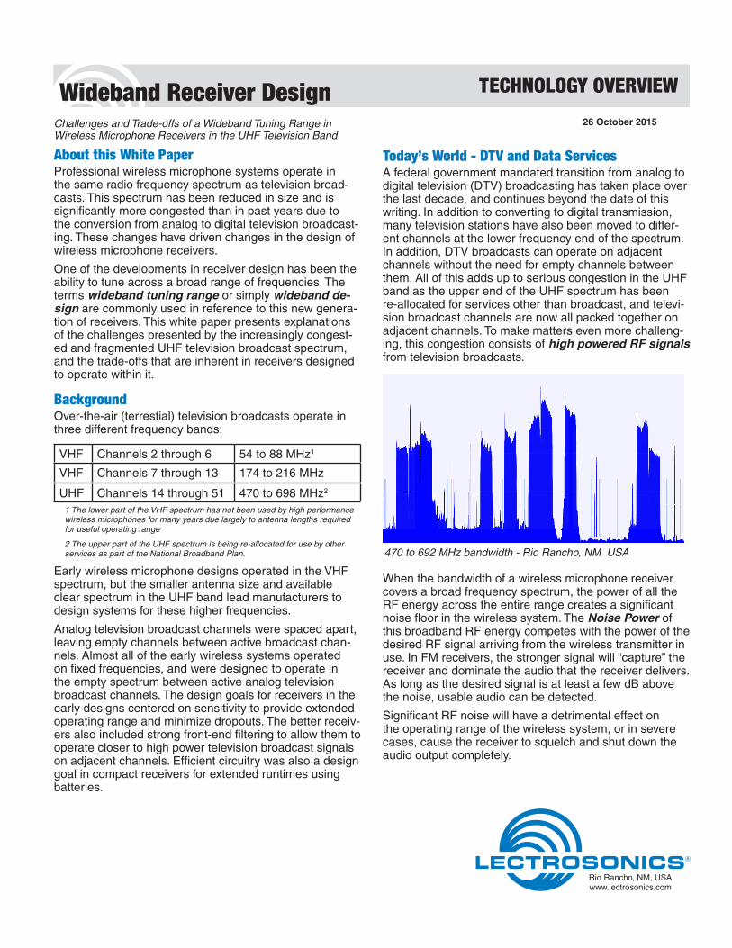
Today’s World - DTV and Data ServicesA federal government mandated transition from analog to digital television (DTV) broadcasting has taken place over the last decade, and continues beyond the date of this writing. In addition to converting to digital transmission, many television stations have also been moved to differ-ent channels at the lower frequency end of the spectrum. In addition, DTV broadcasts can operate on adjacent channels without the need for empty channels between them. All of this adds up to serious congestion in the UHF band as the upper end of the UHF spectrum has been re-allocated for services other than broadcast, and televi-sion broadcast channels are now all packed together on adjacent channels. To make matters even more challeng-ing, this congestion consists of high powered RF signals from television broadcasts.
470 to 692 MHz bandwidth - Rio Rancho, NM USA
When the bandwidth of a wireless microphone receiver covers a broad frequency spectrum, the power of all the RF energy across the entire range creates a significant noise floor in the wireless system. The Noise Power of this broadband RF energy competes with the power of the desired RF signal arriving from the wireless transmitter in use. In FM receivers, the stronger signal will “capture” the receiver and dominate the audio that the receiver delivers. As long as the desired signal is at least a few dB above the noise, usable audio can be detected.
Significant RF noise will have a detrimental effect on the operating range of the wireless system, or in severe cases, cause the receiver to squelch and shut down the audio output completely.
26 October 2015
Wideband Tuning Technology Overview
2
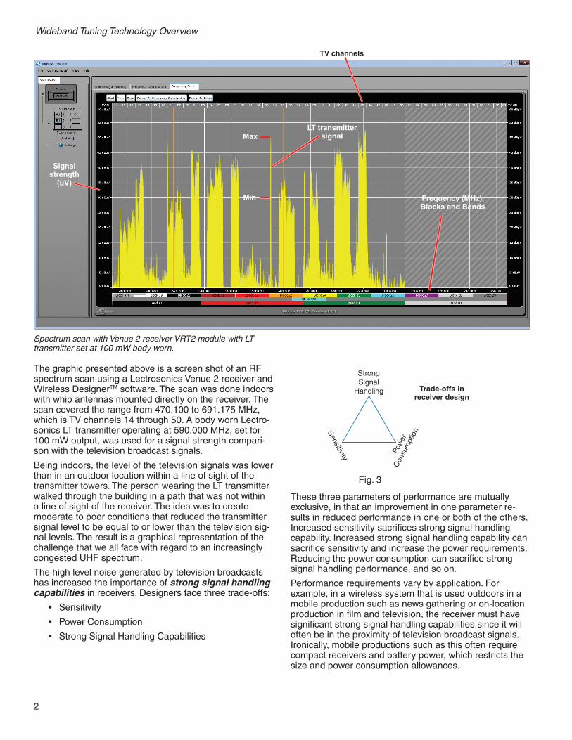
The graphic presented above is a screen shot of an RF spectrum scan using a Lectrosonics Venue 2 receiver and Wireless DesignerTM software. The scan was done indoors with whip antennas mounted directly on the receiver. The scan covered the range from 470.100 to 691.175 MHz, which is TV channels 14 through 50. A body worn Lectro-sonics LT transmitter operating at 590.000 MHz, set for 100 mW output, was used for a signal strength compari-son with the television broadcast signals.
Being indoors, the level of the television signals was lower than in an outdoor location within a line of sight of the transmitter towers. The person wearing the LT transmitter walked through the building in a path that was not within a line of sight of the receiver. The idea was to create moderate to poor conditions that reduced the transmitter signal level to be equal to or lower than the television sig-nal levels. The result is a graphical representation of the challenge that we all face with regard to an increasingly congested UHF spectrum.
The high level noise generated by television broadcasts has increased the importance of strong signal handling capabilities in receivers. Designers face three trade-offs:
• Sensitivity
• Power Consumption
• Strong Signal Handling Capabilities
Strong Signal
Handling
Sensitivity Po
wer
Con
sum
ptio
n
Trade-offs in receiver design
Fig. 3
These three parameters of performance are mutually exclusive, in that an improvement in one parameter re-sults in reduced performance in one or both of the others. Increased sensitivity sacrifices strong signal handling capability. Increased strong signal handling capability can sacrifice sensitivity and increase the power requirements. Reducing the power consumption can sacrifice strong signal handling performance, and so on.
Performance requirements vary by application. For example, in a wireless system that is used outdoors in a mobile production such as news gathering or on-location production in film and television, the receiver must have significant strong signal handling capabilities since it will often be in the proximity of television broadcast signals. Ironically, mobile productions such as this often require compact receivers and battery power, which restricts the size and power consumption allowances.
Spectrum scan with Venue 2 receiver VRT2 module with LT transmitter set at 100 mW body worn.
TV channels
Frequency (MHz), Blocks and Bands
LT transmitter signal
Signal strength
(uV)
Max
Min

3
Wideband Tuning Technology Overview
On the other hand, a system that is installed indoors in a controlled environment such as a worship center, confer-ence facility or stage production where television broad-cast signals are more distant and weaker, strong signal handling capability is a lesser concern, availability of power is not restricted and the receiver can be physically large, such as a rack mount design.
Designing for the Congested UHF SpectrumDesign considerations for a receiver that can withstand strong off channel signals and continue to provide good operating range involves two design elements:
• Effective filtering
• Overload resistant components
Filtering in ReceiversThe signal coming from the antenna is at a low level (in the realm of microvolts) so it has to be amplified signifi-cantly before it can be processed by subsequent stages in the receiver. Simply amplifying the signal without filter-ing will also amplify the noise that accompanies it and likely overload subsequent stages. Instead, a correctly designed front-end is a combination of filtering and gain.
The simplified block diagram shown below illustrates an example of effective filtering in a wireless receiver. The job of the front-end is to filter out unwanted signals and noise and amplify the desired signal to be delivered to the mixer. The mixer combines the signal from an internal oscillator (LO - local oscillator) and the difference signal is delivered to the IF (intermediate frequency) stage. The IF stage amplifiers and filters add additional selectivity and deliver it to a specialized IC that converts the radio frequency signal to an even lower frequency (the 2nd IF). And finally, the signal is amplified and delivered to a pulse counting detector that produces the audio.
A fixed, broadband “barn door” front-end filter has to be wide enough to cover the entire tunable bandwidth of the receiver, which allows a huge amount of RF energy into the receiver. The sum of all the energy across the band-width may be enough to overload the mixer and amplifier stages in the receiver and generate serious amounts of interference inside the receiver. The typical result is very short operating range in the wireless system.
Signals and Noise in Wideband Spectrum
Strong RF signals(TV stations)
Other wirelesssignals
Clear spectrum
A tracking front-end filter provides a much narrower bandwidth, and moves across the tuning range to stay centered on the operating frequency to suppress high powered signals and noise above and below the carrier.
Tracking Filters Suppress Out-of-band Signals
With unwanted signals and noise significantly suppressed at the input to the receiver, subsequent circuit stages can be fully optimized for increased sensitivity.
FILTER FILTER
LO
RX ICPULSE
DETECTOR AUDIOLNAIF
AMPIF
AMPSAW
FILTERSAW
FILTER
1STIF FREQ 2ND
IF FREQ
Wideband Tuning Technology Overview
4
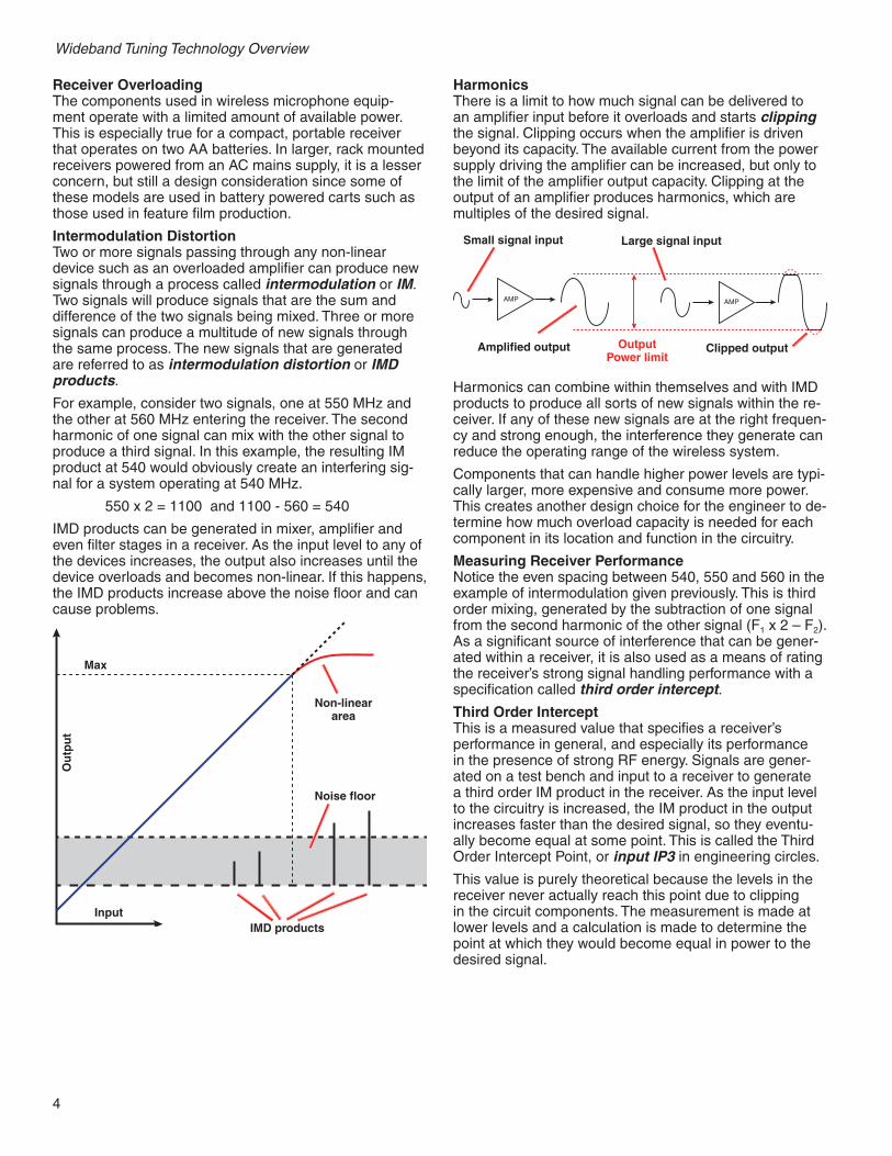
HarmonicsThere is a limit to how much signal can be delivered to an amplifier input before it overloads and starts clipping the signal. Clipping occurs when the amplifier is driven beyond its capacity. The available current from the power supply driving the amplifier can be increased, but only to the limit of the amplifier output capacity. Clipping at the output of an amplifier produces harmonics, which are multiples of the desired signal.
AMP AMP
Small signal input
Amplified output
Large signal input
Clipped outputOutput Power limit
Harmonics can combine within themselves and with IMD products to produce all sorts of new signals within the re-ceiver. If any of these new signals are at the right frequen-cy and strong enough, the interference they generate can reduce the operating range of the wireless system.
Components that can handle higher power levels are typi-cally larger, more expensive and consume more power. This creates another design choice for the engineer to de-termine how much overload capacity is needed for each component in its location and function in the circuitry.
Measuring Receiver PerformanceNotice the even spacing between 540, 550 and 560 in the example of intermodulation given previously. This is third order mixing, generated by the subtraction of one signal from the second harmonic of the other signal (F1 x 2 – F2). As a significant source of interference that can be gener-ated within a receiver, it is also used as a means of rating the receiver’s strong signal handling performance with a specification called third order intercept.
Third Order Intercept This is a measured value that specifies a receiver’s performance in general, and especially its performance in the presence of strong RF energy. Signals are gener-ated on a test bench and input to a receiver to generate a third order IM product in the receiver. As the input level to the circuitry is increased, the IM product in the output increases faster than the desired signal, so they eventu-ally become equal at some point. This is called the Third Order Intercept Point, or input IP3 in engineering circles.
This value is purely theoretical because the levels in the receiver never actually reach this point due to clipping in the circuit components. The measurement is made at lower levels and a calculation is made to determine the point at which they would become equal in power to the desired signal.
Receiver OverloadingThe components used in wireless microphone equip-ment operate with a limited amount of available power. This is especially true for a compact, portable receiver that operates on two AA batteries. In larger, rack mounted receivers powered from an AC mains supply, it is a lesser concern, but still a design consideration since some of these models are used in battery powered carts such as those used in feature film production.
Intermodulation DistortionTwo or more signals passing through any non-linear device such as an overloaded amplifier can produce new signals through a process called intermodulation or IM. Two signals will produce signals that are the sum and difference of the two signals being mixed. Three or more signals can produce a multitude of new signals through the same process. The new signals that are generated are referred to as intermodulation distortion or IMD products.
For example, consider two signals, one at 550 MHz and the other at 560 MHz entering the receiver. The second harmonic of one signal can mix with the other signal to produce a third signal. In this example, the resulting IM product at 540 would obviously create an interfering sig-nal for a system operating at 540 MHz.
550 x 2 = 1100 and 1100 - 560 = 540
IMD products can be generated in mixer, amplifier and even filter stages in a receiver. As the input level to any of the devices increases, the output also increases until the device overloads and becomes non-linear. If this happens, the IMD products increase above the noise floor and can cause problems.
Noise floor
IMD products
Max
Ou
tpu
t
Input
Non-linear area
5
Wideband Tuning Technology Overview
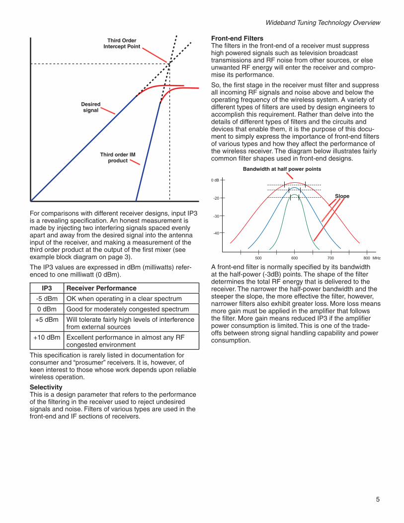
Third Order Intercept Point
Third order IM product
Desired signal
For comparisons with different receiver designs, input IP3 is a revealing specification. An honest measurement is made by injecting two interfering signals spaced evenly apart and away from the desired signal into the antenna input of the receiver, and making a measurement of the third order product at the output of the first mixer (see example block diagram on page 3).
The IP3 values are expressed in dBm (milliwatts) refer-enced to one milliwatt (0 dBm).
IP3 Receiver Performance
-5 dBm OK when operating in a clear spectrum
0 dBm Good for moderately congested spectrum
+5 dBm Will tolerate fairly high levels of interference from external sources
+10 dBm Excellent performance in almost any RF congested environment
This specification is rarely listed in documentation for consumer and “prosumer” receivers. It is, however, of keen interest to those whose work depends upon reliable wireless operation.
SelectivityThis is a design parameter that refers to the performance of the filtering in the receiver used to reject undesired signals and noise. Filters of various types are used in the front-end and IF sections of receivers.
Front-end FiltersThe filters in the front-end of a receiver must suppress high powered signals such as television broadcast transmissions and RF noise from other sources, or else unwanted RF energy will enter the receiver and compro-mise its performance.
So, the first stage in the receiver must filter and suppress all incoming RF signals and noise above and below the operating frequency of the wireless system. A variety of different types of filters are used by design engineers to accomplish this requirement. Rather than delve into the details of different types of filters and the circuits and devices that enable them, it is the purpose of this docu-ment to simply express the importance of front-end filters of various types and how they affect the performance of the wireless receiver. The diagram below illustrates fairly common filter shapes used in front-end designs.
600500 700 800 MHz
0 dB
-20
-30
-40
Bandwidth at half power points
Slope
A front-end filter is normally specified by its bandwidth at the half-power (-3dB) points. The shape of the filter determines the total RF energy that is delivered to the receiver. The narrower the half-power bandwidth and the steeper the slope, the more effective the filter, however, narrower filters also exhibit greater loss. More loss means more gain must be applied in the amplifier that follows the filter. More gain means reduced IP3 if the amplifier power consumption is limited. This is one of the trade-offs between strong signal handling capability and power consumption.

Wideband Tuning Technology Overview
6
IF FiltersThe incoming RF signal from the transmitter (the carrier) must be converted to a lower frequency before audio can be extracted from it. This is accomplished by mixing the carrier with a signal generated by an LO (local oscillator) in the receiver (see block diagram on page 3).
This lower frequency signal is referred to as the IF (inter-mediate frequency). Modern UHF wireless microphone receivers generally use more than one “conversion” to re-duce the frequency. Each stage where a mixer is used to derive a lower frequency is a conversion. Thus, a receiver may be a “double conversion” or a “triple conversion” design, as defined by the number of mixer stages. For example, a typical triple conversion design might convert a UHF carrier at 550 MHz to 244 MHz, then to 10.7 MHz, then to 300 kHz, and deliver the final 300 kHz signal to a detector to produce the audio output.
The first stage in the IF is fed from the output of the first mixer. At this point in the signal chain, unwanted RF en-ergy above and below the carrier has largely been filtered out, so a special type of filter can be used to provide additional selectivity. The goal is to filter the signal down to a point where the bandwidth of the RF energy deliv-ered to the detector is only slightly wider than the modu-lated bandwidth of the signal itself. To accomplish this, IF stages in high-end receivers often use what is called a SAW (surface acoustic wave) filter for this purpose. The “squarish” shape, steep slopes and narrow bandwidth of the filter are ideal for IF filtering.
80
70
60
50
40
30
20
10
0
905.944259.34259.242
Frequency (MHz)
Atte
nuat
ion(
-dB
)
Gro
up d
elay
tim
e (1
.0µ
sec/
Div
)
SAW filters are used at each conversion stage in the IF in much the same manner as front-end filtering is accom-plished: FILTER > GAIN > FILTER > GAIN.
Venue 2 receiver and friends
7
Wideband Tuning Technology Overview
Advanced iQ Front-end Filtering
Tracking Filters
With the transition to DTV in the National Broadband Plan and the congestion in the UHF spectrum it has created, an advanced type of front-end filter has been developed by Lectrosonics. The congestion we now face is com-posed of very high powered RF transmissions from ter-restrial broadcast television signals. Conventional filtering techniques are not always adequate in certain situations.
In addition to congestion from television broadcasts, a theatrical stage production, for example, presents a similar situation. With numerous transmitters operating in close proximity to receiver antennas, the RF signal strength entering the receiver can rival that of a television broadcast.
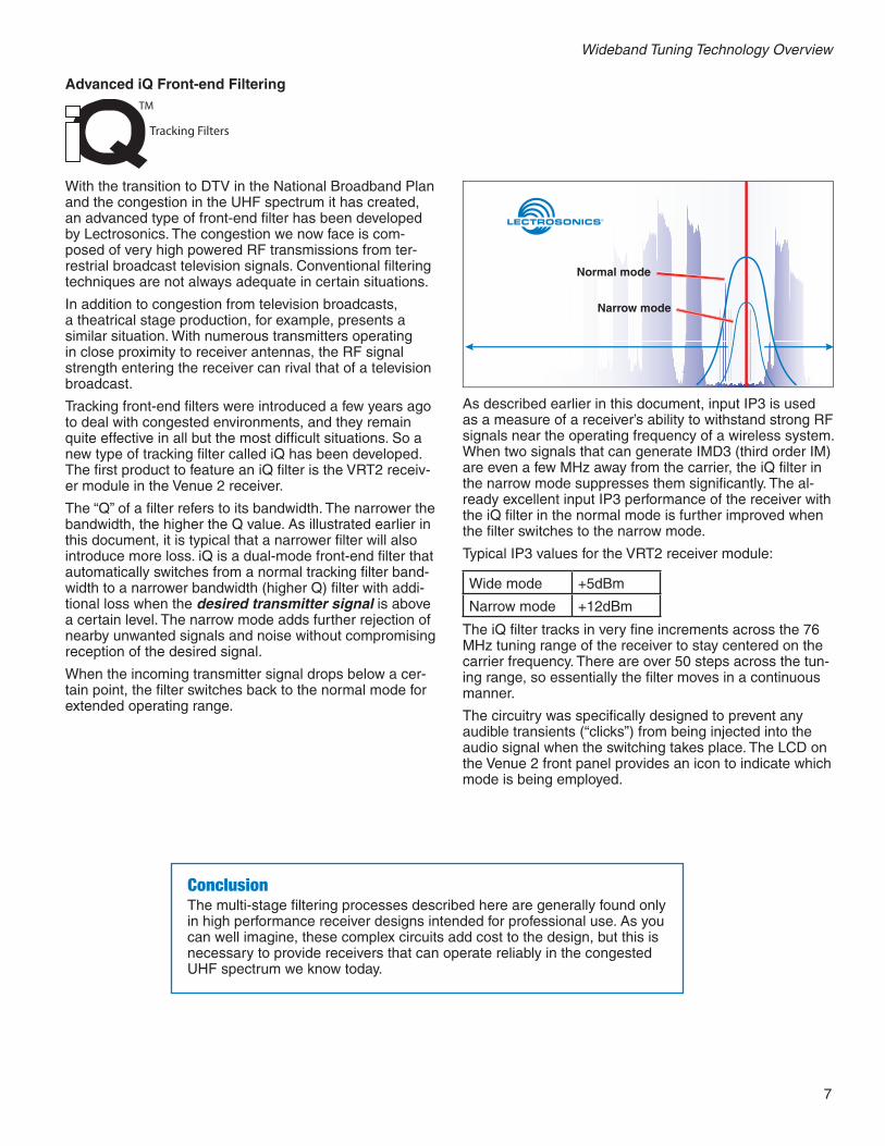
Tracking front-end filters were introduced a few years ago to deal with congested environments, and they remain quite effective in all but the most difficult situations. So a new type of tracking filter called iQ has been developed. The first product to feature an iQ filter is the VRT2 receiv-er module in the Venue 2 receiver.
The “Q” of a filter refers to its bandwidth. The narrower the bandwidth, the higher the Q value. As illustrated earlier in this document, it is typical that a narrower filter will also introduce more loss. iQ is a dual-mode front-end filter that automatically switches from a normal tracking filter band-width to a narrower bandwidth (higher Q) filter with addi-tional loss when the desired transmitter signal is above a certain level. The narrow mode adds further rejection of nearby unwanted signals and noise without compromising reception of the desired signal.
When the incoming transmitter signal drops below a cer-tain point, the filter switches back to the normal mode for extended operating range.
Normal mode
Narrow mode
As described earlier in this document, input IP3 is used as a measure of a receiver’s ability to withstand strong RF signals near the operating frequency of a wireless system. When two signals that can generate IMD3 (third order IM) are even a few MHz away from the carrier, the iQ filter in the narrow mode suppresses them significantly. The al-ready excellent input IP3 performance of the receiver with the iQ filter in the normal mode is further improved when the filter switches to the narrow mode.
Typical IP3 values for the VRT2 receiver module:
Wide mode +5dBm
Narrow mode +12dBm
The iQ filter tracks in very fine increments across the 76 MHz tuning range of the receiver to stay centered on the carrier frequency. There are over 50 steps across the tun-ing range, so essentially the filter moves in a continuous manner.
The circuitry was specifically designed to prevent any audible transients (“clicks”) from being injected into the audio signal when the switching takes place. The LCD on the Venue 2 front panel provides an icon to indicate which mode is being employed.
ConclusionThe multi-stage filtering processes described here are generally found only in high performance receiver designs intended for professional use. As you can well imagine, these complex circuits add cost to the design, but this is necessary to provide receivers that can operate reliably in the congested UHF spectrum we know today.

581 Laser Road NE • Rio Rancho, NM 87124 USA • www.lectrosonics.com+1(505) 892-4501 • fax +1(505) 892-6243 • (800) 821-1121 US and Canada • [email protected]
WidebandTuning_TechOverview.indd
TM Wireless DesignerTM software is a powerful, intuitive control panel for several product families. Among the various options for setup and analysis is a versatile frequency coordination tool. After scanning the spectrum, the results can be imported into the frequency coordinator with a single click. In the frequency coordinator, the suggested operating carriers can be moved manually, or a new set of coordinated frequencies can be generated instantly with a single mouse click.
Potential errors
Selected frequency marker appears bold
Error checking threshold
Frequencies not coordinated
After one-click frequency coordination