Embed Size (px)
Citation preview

Whole-House Audio ControlOwner’s Manual
MC-66 Mult i -Zone Control ler&
MCA-66 Mult i -Zone Control ler /Ampli f ier
Home Theater Direct
Toll free: 866-HTD-AUDIO (483-2834)[email protected]
© Copyright Home Theater Direct, Inc.V.08.16.19
CAUTIONRISK OF ELECTRIC SHOCK
DO NOT OPEN
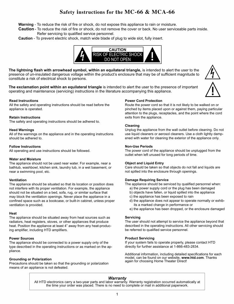
The lightning flash with arrowhead symbol, within an equilateral triangle, is intended to alert the user to the presence of un-insulated dangerous voltage within the product’s enclosure that may be of sufficient magnitude to constitute a risk of electrical shock to persons.
The exclamation point within an equilateral triangle is intended to alert the user to the presence of important operating and maintenance (servicing) instructions in the literature accompanying this appliance.
Read InstructionsAll the safety and operating instructions should be read before the appliance is operated.
Retain InstructionsThe safety and operating instructions should be adhered to.
Heed WarningsAll of the warnings on the appliance and in the operating instructions should be adhered to.
Follow InstructionsAll operating and use instructions should be followed.
Water and MoistureThe appliance should not be used near water. For example, near a bathtub, washbowl, kitchen sink, laundry tub, in a wet basement, or near a swimming pool, etc.
VentilationThe appliance should be situated so that its location or position does not interfere with its proper ventilation. For example, the appliance should not be situated on a bed, sofa, rug, or similar surface that may block the ventilation openings. Never place the appliance in a confined space such as a bookcase, or built-in cabinet, unless proper ventilation is provided.
HeatThe appliance should be situated away from heat sources such as radiators, heat registers, stoves, or other appliances that produce heat. Position the appliance at least 4” away from any heat-produc-ing amplifier, including HTD amplifiers.
Power SourcesThe appliance should be connected to a power supply only of the type described in the operating instructions or as marked on the ap-pliance.
Grounding or PolarizationPrecautions should be taken so that the grounding or polarization means of an appliance is not defeated.
Power Cord ProtectionRoute the power cord so that it is not likely to be walked on or pinched by items placed upon or against them, paying particular attention to the plugs, receptacles, and the point where the cord exits from the appliance.
CleaningUnplug the appliance from the wall outlet before cleaning. Do not use liquid cleaners or aerosol cleaners. Use a cloth lightly damp-ened with water for cleaning the exterior of the appliance only.
Non-Use PeriodsThe power cord of the appliance should be unplugged from the outlet when left unused for long periods of time.
Object and Liquid EntryCare should be taken so that objects do not fall and liquids are not spilled into the enclosure through openings.
Damage Requiring ServiceThe appliance should be serviced by qualified personnel when:
a) the power supply cord or the plug has been damagedb) objects have fallen, or liquid spilled into the appliancec) the appliance has been exposed to raind) the appliance does not appear to operate normally or exhib-
its a marked change in performance or e) the appliance has been dropped, or the enclosure damaged
ServicingThe user should not attempt to service the appliance beyond that described in the operating instructions. All other servicing should be referred to qualified service personnel.
Product ServicingIf your system fails to operate properly, please contact HTD directly for further assistance at 1-866-483-2834.
Additional information, including detailed specifications for each model, can be found on our website, www.htd.com. Thanks again for choosing Home Theater Direct!
WarrantyAll HTD electronics carry a two-year parts and labor warranty. Warranty registration occurred automatically at
the time your order was placed. There is no need to complete or mail in additional paperwork.
Warning - To reduce the risk of fire or shock, do not expose this appliance to rain or moisture.Caution - To reduce the risk of fire or shock, do not remove the cover or back. No user serviceable parts inside. Refer servicing to qualified service personnel.Caution - To prevent electric shock, match wide blade of plug to wide slot, fully insert.
Safety instructions for the MC-66 & MCA-66
1

1. Lisez ces instructions.
2. Conservez ces instructions.
3. Respectez tous les avertissements.
4. Suivez les instructions.
5. Ne pas utiliser cet appareil près de l’eau.
6. Nettoyez uniquement avec un chiffon humide.
7. Ne pas obstruer les ouvertures de ventilation. Installer conformément aux instructions du fabricant.
8. Ne pas installer près de sources de chaleur telles que des radiateurs, registres de chaleur, poêles ou autres appareils (incluant les amplificateurs) qui produisent de la chaleur.
9. Ne pas contourner le dispositif de sécurité de la fiche polarisée type. Une fiche polarisée possède deux lames dont une plus large que l’autre. La lame large est fournie pour votre sécurité. Si la fiche fourniene rentre pas dans votre prise, consultez un électricien pour remplacer la prise obsolète.
10. Protégez le cordon d’alimentation ne soit piétiné ou pincé, en particulier au bouchon, prises de courant, et au point où ils sortent de l’appareil.
11. Utilisez uniquement des fixations / accessoires spécifiés par le fabricant.
12. Utilisez seulement avec un chariot, un support, un trépied, une console ou table spécifié par le fabricant ou vendu avec l’appareil. Lorsque vous utilisez un chariot, soyez prudent lorsque vous déplacez l’ensemble chariot / appareil pour éviter les blessures en cas de chute.
13. Débranchez cet appareil durant les orages ou si inutilisé pendant de longues périodes de temps.
14. Confiez toute réparation à un personnel qualifié. Une réparation est nécessaire lorsque l’appareil a été endommagé de quelque façon que ce cordon d’alimentation ou la fiche est endommagé, du liquide a été renversé ou des objets sont tombés dans l’appareil, l’appareil a été exposé à la pluie ou à l’humidité, ne fonctionne pas normalement , ou s’il est tombé.
AVERTISSEMENT: Pour réduire le risque d’incendie ou un choc électrique, ne pas exposer cet appareil à la pluie ou à l’humidité. L’appareil ne doit pas être exposé au ruissellement ou aux éclaboussures et aucun tobjet rempli de liquide, comme des vases, ne doit être placé sur l’appareil
Consignes de sécurité importantes
2

3This Page is Intentionally Blank

4
If you have any questions, we can be reached [email protected] or toll free 1-866-HTD-AUDIO (483-2834)
Whole-House Audio Control Owner’s Manual
Introduction to the MC-66 & MCA-66 Whole-House Audio Control System
The MC-66 is a six source, six zone stereo audio controller that easily allows you to distribute sound throughout your home. The MCA-66 includes these same features plus a built-in 12-channel amplifier. Both units are controlled by the keypad(s) located within each zone and/or with HTD’s MC App on iPhone and Android devices. With the MC-66 & MCA-66, each of the six zones independently selects from up to six centrally located sources. This means each zone can play a completely different source. Also, from any keypad, you can easily turn on all zones to the same source. We refer to this as “party mode”. You can also turn off all zones with the press of a single button. Tone control (bass/treble) and balance allows each zone to be independently set for the best sound in that zone. We have also developed the MC App (for iPhone and Android devices) which expands this functionality providing wireless control. The controller, keypads and HTD MC App have been designed to make both installation and every-day use intuitive and user friendly.
If, after reading this manual, you have any questions, please call us toll free at 1-866-483-2834 during business hours (M-F 8am-6pm CST). We’re here to help and to make sure you are getting the most out of your new whole-house audio system.
IMPORTANT WARNINGS AND HELPFUL TIPS Please note that while we refer to Cat5e throughout this manual, Cat5, and Cat6 can also be used with equal effectiveness.
1. Never connect or disconnect Cat5e cable from the keypad or controller while the controller ispowered on.
2. Never connect or disconnect speaker cable from a speaker or the controller while the
controller is powered on. 3. ONLY TERMINATE CAT5e CABLES WITH RJ-45 CONNECTORS USING THE 568-A OR
568-B STANDARD (see page 17). You cannot simply connect the 8 wires in the same order at both ends. Cat5e cable consists of 4 twisted pairs of cable and some signals are sent down a particular twisted pair in order to prevent cross-talk. Failure to follow one of the standards will cause the system to act erratically or be entirely inoperable.
Note: Because 568-B is the more recent standard, we encourage you to use it instead of 568-A.
4. When connecting (daisy-chaining) more than one keypad into the SAME zone, each keypad must also have a unique combination of shorting bars installed. Each keypad includes 2 shorting bars already installed - this represents one of the four possible combinations. Removing only the left shorting bar is a second combination; removing only the right is a third; and removing both shorting bars is a fourth combination.
We reference DMA-1240 in several examples throughout this manual, but either DMA-1275 or DMA-1240ADS can be substitued.
MC-66 Multi-Zone Controller
MCA-66 Multi-Zone Controller/Amplifier
Power
Multiroom Controller/Amplifier MCA-66
Protection
Zone Status
1 2 3 4 5 6
FUSE
T8A
/250
V
AC 1
20V~
60Hz
Powe
r Con
sum
ptio
n: 6
10WIR OUT IR IN
SOURCE INPUT
RS232 INTERFACE
KEYPAD PORTS
1 2 3 4 5 6
L
R
43
21
5 6
12V/DCTRIGGER
OUTIN
L R
PRE OUTZONE1
FIXED VARIABLE
L R
PRE OUTZONE2
FIXED VARIABLE
L R
PRE OUTZONE3
FIXED VARIABLE
L R
PRE OUTZONE4
FIXED VARIABLE
L R
PRE OUTZONE5
FIXED VARIABLE
L R
PRE OUTZONE6
FIXED VARIABLE
SPEAKER OUTPUT 8 OHMS/20WRIGHTLEFT RIGHTLEFT RIGHTLEFT RIGHTLEFT RIGHTLEFT RIGHTLEFT
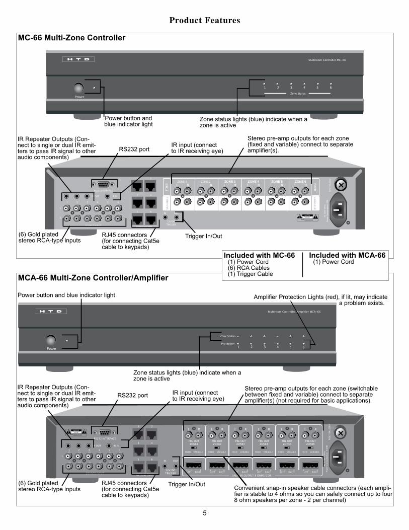
Included with MC-66(1) Power Cord(6) RCA Cables(1) Trigger Cable
Included with MCA-66(1) Power Cord
5
Product Features
Power
Multiroom Controller MC-66
Zone Status
1 2 3 4 5 6
FUSE
T1A
/250
V
AC 1
20V~
60H
zPo
wer
Con
sum
ptio
n: 7
0W
IR OUT IR IN
SOURCE INPUT
RS232 INTERFACE
KEYPAD PORTS
1 2 3 4 5 6
L
R
43
21
5 6
12V/DCTRIGGER
OUTIN
ZONE 1L R L R L R L R L RL R
ZONE 2 ZONE 3 ZONE 4 ZONE 5 ZONE 6
VAR
IAB
LE VA
RIA
BLE
FIXE
D
FIXEDPower
Multiroom Controller MC-66
Zone Status1 2 3 4 5 6
Power button and blue indicator light
Zone status lights (blue) indicate when a zone is active
IR Repeater Outputs (Con-nect to single or dual IR emit-ters to pass IR signal to other audio components)
Stereo pre-amp outputs for each zone (fixed and variable) connect to separate amplifier(s).
RJ45 connectors(for connecting Cat5ecable to keypads)
Trigger In/Out(6) Gold plated stereo RCA-type inputs
RS232 port
Convenient snap-in speaker cable connectors (each ampli-fier is stable to 4 ohms so you can safely connect up to four 8 ohm speakers per zone - 2 per channel)
Amplifier Protection Lights (red), if lit, may indicate a problem exists.
IR Repeater Outputs (Con-nect to single or dual IR emit-ters to pass IR signal to other audio components)
Stereo pre-amp outputs for each zone (switchable between fixed and variable) connect to separate amplifier(s) (not required for basic applications).
RJ45 connectors(for connecting Cat5ecable to keypads)
Trigger In/Out(6) Gold plated stereo RCA-type inputs
RS232 port
Power button and blue indicator light
Zone status lights (blue) indicate when a zone is active
IR input (connect to IR receiving eye)
IR input (connect to IR receiving eye)

KC7 Keypad Control*(Optional)
KC6 Keypad Control(Optional)
*Throughout the owner’s manual an image of the KC6 keypad is used in various situations. It should be known that in all such situations a KC7 can be used in place of a KC6.
Included with MCA-66(1) Power Cord
Sold Separately
Product Features (CONT.)
Back-lit, soft touch buttons
Back-lit, soft touch buttons - Screen and buttons will remain lit for 30 seconds at which point the lights will extinguish until any button is pressed.
During setup mode, use these buttons to set treble, bass, and balance for each zone
Source buttons- Used to select source and to change options in the setup menu.
Volume (up/down) - Used to adjust volume level. Also both buttons can be pressed simul-taneously to enter setup mode.
Volume (up/down) Press both and hold for three seconds to enter setup.
IR receiving eye passes IR signals to other centrally located equipment (use a universal remote to control all of your equipment)
IR receiving eye passes IR signals to other centrally located equipment (use a universal remote to control all of your equipment)
Power Button - Multi-function but-ton used to power on, power off, and mute the keypad. Can also be used to power off all keypads.
Power Button - Multi-function but-ton used to power on, power off, and mute the keypad. Can also be used to power off all keypads.
Volume indicator lights
Select from up to six centrally located sources
LCD Screen - displays selected source, volume level, and setup menu options.
Two RJ45 con-nectors - Use one for connect-ing Cat5e cable to controller. Optionally, use the other RJ45 connector to add a second key-pad in the same zone.
“Screwless” Decora style frame (includ-ed) snaps in place for a professional appearance.
“Screwless” Decora style frame (included) snaps in place for a professional appear-ance.
IR emitters are used in conjuction with the KC6 (or KC7) keypad and any centrally located source’s IR remote to control that source from any zone with a keypad. See the Emitter section in this manual for more information.
1 2
4
65
3
VolVol
Power/Mute
VolVol
Power/Mute
SRC2
59 Source
6
1 2
4
65
3
VolVol
Power/Mute
Double Emitter Single
Emitter
Two RJ45 connectors - Use one for connect-ing Cat5e cable to controller. Optionally, use the other RJ45 connector to add a second keypad in the same zone.
How to Connect
7
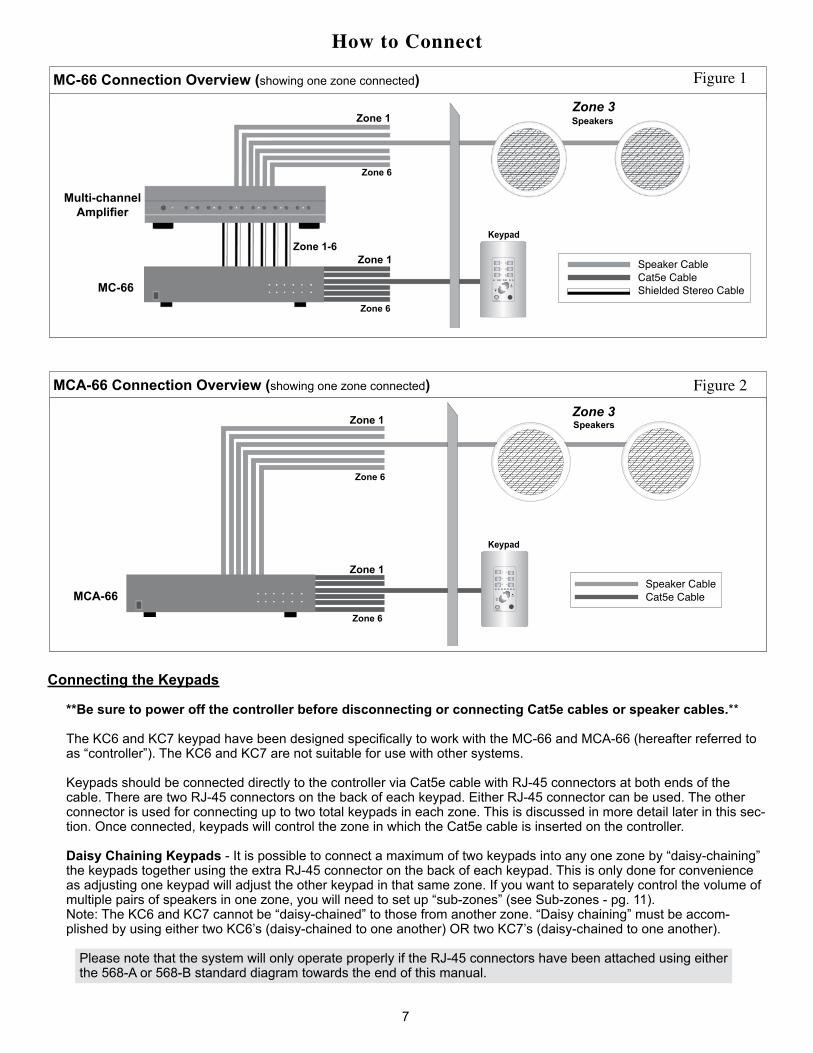
MC-66 Connection Overview (showing one zone connected)
Keypad
Shielded Stereo CableCat5e Cable Speaker Cable
Zone 3SpeakersZone 1
Zone 1Zone 1-6
Multi-channel Amplifier
MC-66
Zone 6
Zone 6
1 2
4
65
3
VolVol
Power/Mute
MCA-66 Connection Overview (showing one zone connected)
Zone 3
Keypad
Figure 2
Figure 1
SpeakersZone 1
Zone 1
Zone 6
Zone 6
MCA-66
Connecting the Keypads
**Be sure to power off the controller before disconnecting or connecting Cat5e cables or speaker cables.**
The KC6 and KC7 keypad have been designed specifically to work with the MC-66 and MCA-66 (hereafter referred to as “controller”). The KC6 and KC7 are not suitable for use with other systems. Keypads should be connected directly to the controller via Cat5e cable with RJ-45 connectors at both ends of the cable. There are two RJ-45 connectors on the back of each keypad. Either RJ-45 connector can be used. The other connector is used for connecting up to two total keypads in each zone. This is discussed in more detail later in this sec-tion. Once connected, keypads will control the zone in which the Cat5e cable is inserted on the controller.
Daisy Chaining Keypads - It is possible to connect a maximum of two keypads into any one zone by “daisy-chaining” the keypads together using the extra RJ-45 connector on the back of each keypad. This is only done for convenience as adjusting one keypad will adjust the other keypad in that same zone. If you want to separately control the volume of multiple pairs of speakers in one zone, you will need to set up “sub-zones” (see Sub-zones - pg. 11). Note: The KC6 and KC7 cannot be “daisy-chained” to those from another zone. “Daisy chaining” must be accom-plished by using either two KC6’s (daisy-chained to one another) OR two KC7’s (daisy-chained to one another).
Please note that the system will only operate properly if the RJ-45 connectors have been attached using either the 568-A or 568-B standard diagram towards the end of this manual.
Cat5e Cable Speaker Cable
1 2
4
65
3
VolVol
Power/Mute
How to Connect
8
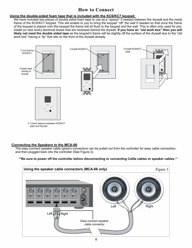
Using the double-sided foam tape that is included with the KC6/KC7 keypad: We have included two pieces of double sided foam tape to use as a “spacer” if needed between the drywall and the metal frame of the KC6/KC7 keypad. This will enable to you to bring the keypad “off” the wall if needed so that once the frame of the keypad is placed onto the keypad the frame will sit flush to the keypad and the wall. This is often only used for pre-install (or new work) electrical boxes that are recessed behind the drywall. If you have an “old work box” then you will likely not need the double sided tape as the keypad’s frame will be slightly off the surface of the drywall due to the “old work box” having a “lip” that sits on the front of the drywall already.
1.Cut hole for KC6/KC7
2.Apply tape directly to drywall
3.Install KC6/KC7
4.Install KC6/KC7 plate
5. Check distance between KC6/KC7 plate and Drywall
VolVol
Power/Mute
Source
VolVol
Power/Mute
Source
VolVol
Power/Mute
Source
VolVol
Power/Mute
Source
1.Cut hole for KC6/KC7
2.Apply tape directly to drywall
3.Install KC6/KC7
4.Install KC6/KC7 plate
5. Check distance between KC6/KC7 plate and Drywall
VolVol
Power/Mute
Source
VolVol
Power/Mute
Source
VolVol
Power/Mute
Source
VolVol
Power/Mute
Source
1.Cut hole for KC6/KC7
2.Apply tape directly to drywall
3.Install KC6/KC7
4.Install KC6/KC7 plate
5. Check distance between KC6/KC7 plate and Drywall
VolVol
Power/Mute
Source
VolVol
Power/Mute
Source
VolVol
Power/Mute
Source
VolVol
Power/Mute
Source
1.Cut hole for KC6/KC7
2.Apply tape directly to drywall
3.Install KC6/KC7
4.Install KC6/KC7 plate
5. Check distance between KC6/KC7 plate and Drywall
VolVol
Power/Mute
Source
VolVol
Power/Mute
Source
VolVol
Power/Mute
Source
VolVol
Power/Mute
Source
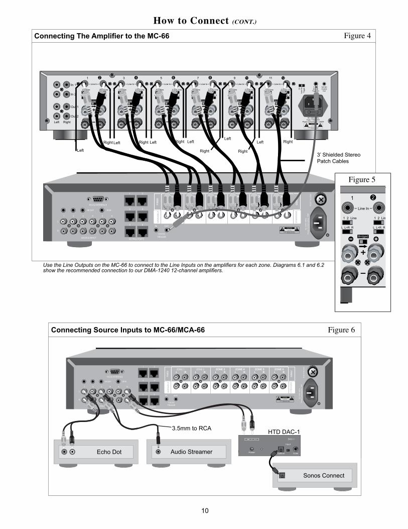
Connecting the Speakers to the MCA-66The easy-connect speaker cable (green) connectors can be pulled out from the controller for easy cable connection, and then plugged back into the controller (See Figure 3).
**Be sure to power off the controller before disconnecting or connecting Cat5e cables or speaker cables.**
Using the speaker cable connectors (MCA-66 only) Figure 3
FUSE
T8A
/250
V
AC 1
20V~
60Hz
Powe
r Con
sum
ptio
n: 6
10WIR OUT IR IN
SOURCE INPUT
RS232 INTERFACE
KEYPAD PORTS
1 2 3 4 5 6
L
R
43
21
5 6
12V/DCTRIGGER
OUTIN
L R
PRE OUTZONE1
FIXED VARIABLE
L R
PRE OUTZONE2
FIXED VARIABLE
L R
PRE OUTZONE3
FIXED VARIABLE
L R
PRE OUTZONE4
FIXED VARIABLE
L R
PRE OUTZONE5
FIXED VARIABLE
L R
PRE OUTZONE6
FIXED VARIABLE
SPEAKER OUTPUT 8 OHMS/20WRIGHTLEFT RIGHTLEFT RIGHTLEFT RIGHTLEFT RIGHTLEFT RIGHTLEFT
Left Right+ - +-
+--+Left Right
Easy-connect speaker cable connector

9
How to Connect (CONT.)
Strip each cable approx. 1/4” and tightly twist the copper wires. Loosen the connection points on the easy-connect speaker cable connectors as necessary using a screwdriver. Insert the cables using the following standards and then re-tighten the connection points:
When using 2-conductor Cables:
Red = positiveBlack = negative
When using 4-conductor Cables:
Red = right positiveBlack = right negativeWhite = left positiveGreen = left negative
Note: make sure that there isn’t too much exposed wire and that all connections are tidy. Any stray wires touching neighbor-ing connectors or wires could cause the unit to go into “protect mode”.
Important Information about the MCA-66 Controller/AmplifierThe MCA-66 includes a built-in 12 channel amplifier. This is essentially 6 stereo amplifiers, one stereo amplifier per zone. Each stereo amplifier includes its own signal sensing capability so that if the keypad is turned off, or if the source currently selected by the keypad is not outputting a signal, the amplifier in that zone will automatically go into stand-by mode. As soon as a signal is detected, the controller/amplifier will power up. This keeps the entire amplifier operating as efficiently as pos-sible.
The amplifiers are designed to be 4 ohm stable. This allows you to connect up to two pairs of 8 ohm speakers (in parallel) into each zone. (note: all HTD brand speakers are 8 ohms). The easy-connect speaker cable connectors supplied for each zone can accept up to 14-gauge cable (the lower the gauge number the thicker the cable, e.g. 14-gauge cable is thicker than 16).
On the back of the MCA-66, you will find Fixed/Variable switches and RCA connections that correspond to each zone. These will only be used when additional amplification is necessary (i.e. adding sub-zones or more than 4 speakers in a zone). Typi-cally operations require that each zone’s switch be set to “Variable”. This allows the keypad to control the volume level in that zone. Setting the switch to “Fixed” is recommended when you set up multiple sub-zones (see Sub-zones, pg. 11) in one zone where each of the speakers in that zone are independently controlled with attenuators (volume controls) separately. Note that the Fixed/Variable switch has no effect on the speaker level outputs on the MCA-66 and only effect the output com-ing from the RCA connections. Thus, using the fixed switch position is used exclusively for an application utilizing a seperate amplifer and volume control (AKA not the amplifier within the MCA-66).
Connecting the Speakers: MC-66 (seperate amplifier required)The MC-66 does not include a built-in amplifier so you need to add a separate multi-channel amplifier. A 12-channel amplifier such as the DMA-1240, DMA-1240ADS, or DMA-1275 is a good match because these amplifiers can easily be set up for 6 stereo zones.
Connect each zone to the multi-channel amplifier using stereo RCA-type patch cables as shown in Figure 4. In most cases, you should plug the RCA patch cables into the “Variable” plugs on the back of the MC-66. This allows the keypad to con-trol the volume level in that zone. Plugging an RCA cable into the “Fixed” plug position is recommended when you set up multiple sub-zones (see Sub-zones, pg. 11) in one zone where each of the pairs of speakers in that zone are independently controlled with attenuators (volume controls) sold separately.
**Speaker cables are connected to the multi-channel amplifier as instructed by the owner’s manual for that amplifier.**
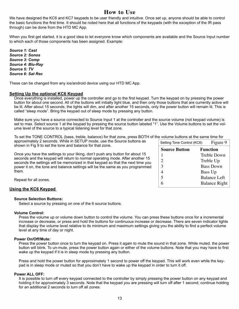
Connecting Source Components (see figure 6)Any audio component with a stereo analog RCA-type output can be connected directly to one of the 6 Source Inputs located on the back of the controller using RCA-type shielded stereo patch cables (not included). Note that 3.5mm to RCA adapters can also be used (not included).
For audio sources that only have a digital or optical out, an HTD Digital-to-Analog Converter (DAC) can be used to convert a digital signal to an analog signal.
Some audio sources may only offer a 3.5mm (headphone jack output). For these devices a simple 3.5mm to RCA converter cable can be used.
10
How to Connect (CONT.)
Connecting Source Inputs to MC-66/MCA-66
Power
Multiroom Controller MC-66
Zone Status
1 2 3 4 5 6
FUSE
T1A
/250
V
AC 1
20V~
60H
zPo
wer
Con
sum
ptio
n: 7
0W
IR OUT IR IN
SOURCE INPUT
RS232 INTERFACE
KEYPAD PORTS
1 2 3 4 5 6
L
R
43
21
5 6
12V/DCTRIGGER
OUTIN
ZONE 1L R L R L R L R L RL R
ZONE 2 ZONE 3 ZONE 4 ZONE 5 ZONE 6
VAR
IAB
LE VA
RIA
BLE
FIXE
D
FIXED
Echo Dot Audio Streamer
HTD DAC-1
Figure 6
tv
Power Optical Coax
Input
DAC-1
FUSE
T1A
/250
V
AC 1
20V~
60H
zPo
wer
Con
sum
ptio
n: 7
0W
IR OUT IR IN
SOURCE INPUT
RS232 INTERFACE
KEYPAD PORTS
1 2 3 4 5 6
L
R
43
21
5 6
12V/DCTRIGGER
OUTIN
VARI
ABLE
FI
XED
ZONE 1L R L R L R L R L RL R
ZONE 2 ZONE 3 ZONE 4 ZONE 5 ZONE 6
VARIABLE FIXED
tv
Power Optical Coax
Input
DAC-1
FUSE
T1A
/250
V
AC 1
20V~
60H
zPo
wer
Con
sum
ptio
n: 7
0W
IR OUT IR IN
SOURCE INPUT
RS232 INTERFACE
KEYPAD PORTS
1 2 3 4 5 6
L
R
43
21
5 6
12V/DCTRIGGER
OUTIN
VARI
ABLE
FI
XED
ZONE 1L R L R L R L R L RL R
ZONE 2 ZONE 3 ZONE 4 ZONE 5 ZONE 6
VARIABLE FIXED
3.5mm to RCA
Power
Multiroom Controller MC-66
Zone Status
1 2 3 4 5 6FU
SE T
1A/2
50V
AC 1
20V~
60H
zPo
wer
Con
sum
ptio
n: 7
0W
IR OUT IR IN
SOURCE INPUT
RS232 INTERFACE
KEYPAD PORTS
1 2 3 4 5 6
L
R
43
21
5 6
12V/DCTRIGGER
OUTIN
ZONE 1L R L R L R L R L RL R
ZONE 2 ZONE 3 ZONE 4 ZONE 5 ZONE 6
VAR
IAB
LE VA
RIA
BLE
FIXE
D
FIXED
Connecting The Amplifier to the MC-66
Right Left
Right
LeftRight Right LeftLeft
Left Right3’ Shielded Stereo Patch Cables
RightLeft
Use the Line Outputs on the MC-66 to connect to the Line Inputs on the amplifiers for each zone. Diagrams 6.1 and 6.2 show the recommended connection to our DMA-1240 12-channel amplifiers.
Figure 5
Figure 4
Sonos Connect

How to Connect (CONT.)
Sub-ZonesA sub-zone is an area that has independent volume control but that is forced to listen to the source selected by the keypad in the primary zone. As an example, you might have a kitchen and dining area that are located side-by-side. In this case, you will often choose to have the kitchen be the primary zone with volume controlled by the keypad and the dining area’s volume controlled by a more traditional rotary or slide-type volume control. Depending on your situation, you may or may not need to add more amplifier channels than that already provided by the multi-channel amplifier.
Sub-zones are extensive subjects on their own. The large amount of variables and customization that can be required to cor-rectly wire/control sub-zones make them a difficult subject to cover here. As such, if you would like more information on how you can setup and control a sub-zone in your whole home audio project, please contact HTD at [email protected] or toll free 1-866-HTD-AUDIO (483-2834).
Using the Trigger In/Out (MC-66/DMA-1240, DMA-1240ADS DMA-1275):
**Be sure to power off the controller before disconnecting or connecting Trigger Cables.**
Trigger In: Only use this input when you want to turn on the controller at the same time another device is turned on. To do this, the other device must have a low voltage trigger output and be connected to the controller via a 3.5mm mono connec-tor patch cable. As an example, you might want the controller powered on when you power on a particular CD player. When the CD player is powered on, it sends a low voltage signal to the trigger input on the controller. When the controller detects this signal, it powers up out of sleep mode and all of the keypads will power on. IMPORTANT: Please note that while the CD Player in this example is powered on, the controller and keypads can NOT be powered off.
Trigger Out: Use the trigger output to automatically power up an external device with a low voltage trigger input whenever a zone is powered on. As an example, with the MC-66 controller, it is often a good idea to con-nect the Trigger Out to the Trigger In on the external multi-channel amplifier using a 3.5mm mono connector patch cable. That way, the multi-channel amplifier will only be powered up when a zone is active. Once all zones have been powered off, the multi-channel amplifier will return to sleep mode.
On - Auto On - Trigger Switch (MC-66/DMA-1240, DMA-1240ADS or DMA-1275):For the most energy efficient setting, set this switch to Trigger and connect a 3.5mm mono patch cable from the Trigger Out on the MC-66 to the Trigger In on the DMA-1240. If a zone is powered on, the low voltage output will be active which will sig-nal the DMA-1240 to “wake up” and power on. If all of the zones are powered off, the trigger output will be inactive and the DMA-1240 will automatically return to sleep mode. Please note that the Power Button on the front of the DMA-1240 should be pressed in with the blue power indicator light illuminated. Trigger mode, using the included Trigger cable is preferred. We generally don’t recommend use of the “Auto” setting for this application. “Auto” mode detects the presence of an audio input signal. If that audio input signal strength is low (as from audio streamers, computers, and other sources) it can cause the amplifier to either “turn off”, or not turn on.
To Whole-house Audio Contoller
To Whole-house Audio Contoller
To Whole-house Audio Contoller
To Whole-house Audio Contoller
Use the double-sided tape included with the IR emitter to attach the emitter to the devices’s IR recieving eye.
This emitter is attached in the appropriate loca-tion. The emitter cable is running under this device to the whole-house audio controller.
This is a side view show-ing how the IR emitter should be attached to the device that is being controlled.
11
Connecting IR Emitters to devices
On
Aut
o O
nTr
igge
r
Home Theater Receiver
Home Theater Receiver
Figure 7

How to Connect (CONT.)
12
Connecting IR Emitters and an IR Receiving EyeThe controller includes the ability to pass infrared (IR) signals on to other components located nearby. This allows the controller and source components to be located in a centralized (and often hidden) location and still be controlled by the IR remotes supplied with each of the source components. The IR signals are sent to the controller either via the IR receiving eyes located on each keypad, or via an IR receiving eye connected directly to the 3.5 mm input on the back of the controller (the IR input on the back of the controller is a source passthrough only). The IR signals are passed along to the source components by connecting IR emitters to the back of the controller and placing them in front of the receiving eyes on the source components. See figure 8. Tip: Many of our customers find it useful to buy a universal or learning remote control that can memorize the functionality of all of the source components. Keeping one (or more) of these remote controls in a convenient location allows you to control all of the source components by simply aiming the remote at any of the keypads located throughout the house.
Connecting IR Emitters to devicesAlthough the previous diagrams show the IR emitters placed near the devices that you wish to control, these diagrams are meant to basically show how the emitters/receiving eyes fit into your whole-house audio setup.
The emitters are packaged along with double-sided tape which allow the emitters to attach directly to the devices you wish to control. These emitters should be placed directly onto the IR receiving eye of the devices. Figure 7 on page 11 shows specifi-cally where these IR emitters should be placed.
The IR emitters shown have a flash-back feature built into the device to visually signal when a command has been “passed through” the system. This flash-back indicator is located on the top side of the emitter. The actual emitting eye within the emitter is located on the bottom portion of the emitter. This is why the emitters should be attached on top of the device’s receiving eye that you wish to control.
FUSE
T1A
/250
V
AC 1
20V~
60Hz
Powe
r Con
sum
ptio
n: 7
0W
IR OUT IR IN
SOURCE INPUT
RS232 INTERFACE
KEYPAD PORTS
1 2 3 4 5 6
L
R
43
21
5 6
12V/DCTRIGGER
OUTIN
L R
PRE OUTZONE1
FIXED VARIABLE
L R
PRE OUTZONE2
FIXED VARIABLE
L R
PRE OUTZONE3
FIXED VARIABLE
L R
PRE OUTZONE4
FIXED VARIABLE
L R
PRE OUTZONE5
FIXED VARIABLE
L R
PRE OUTZONE6
FIXED VARIABLE
Home Entertainment Cabinet
Making use of Infrared Capability
Using IR Emitter(s)
Using the IR Receiver Eye (optional)
Connect Emitters to the Emitter Outputs on the back of the controller. Place each IR Emitter directly on top of the audio component’s infrared eye. (see the component’s owner’s manual to determine this location).
Connect the IR Receiver Eye to the IR Receiver input on the back of the controller. Position the Receiver Eye outside of your cabinet or closet in a position where it can detect your IR remote. It is only necessary when you don’t have a keypad located nearby.
Zone 1-6Equipment RoomYour ownremote control
VOLUME
VOLUME
Your ownremotecontrol
(IR Receiving Eye, Emitters, and Keypad are sold separately)
1 2
4
65
3
Vol
Vol
Power/Mute
Figure 8
HTD Whole-House Audio Controller
HTD 12-Channel Amplifier
CD/DVD Player
Sat Rcvr
Tuner
Power
Multiroom Controller MC-66
Zone Status
1 2 3 4 5 6
1 2
4
65
3
VolVol
Power/Mute
We have designed the KC6 and KC7 keypads to be user friendly and intuitive. Once set up, anyone should be able to control the basic functions the first time. It should be noted here that all functions of the keypads (with the exception of the IR pass through) can be done from the HTD MC App.
When you first get started, it is a good idea to let everyone know which components are available and the Source Input number to which each of those components has been assigned. Example:
Source 1: CastSource 2: SonosSource 3: CompSource 4: Blu-RaySource 5: TVSource 6: Sat Rec
These can be changed from any ios/android device using our HTD MC App.
Setting Up the optional KC6 KeypadOnce everything is installed, power up the controller and go to the first keypad. Turn the keypad on by pressing the power button for about one second. All of the buttons will initially light blue, and then only those buttons that are currently active will be lit. After about 15 seconds, the lights will dim, and after another 15 seconds, only the power button will remain lit. This is called “sleep mode”. Bring the keypad out of sleep mode by pressing any button. Make sure you have a source connected to Source Input 1 at the controller and the source volume (not keypad volume) is set to max. Select source 1 at the keypad by pressing the source button labeled “1”. Use the Volume buttons to set the vol-ume level of the source to a typical listening level for that zone. To set the TONE CONTROL (bass, treble, balance) for that zone, press BOTH of the volume buttons at the same time for approximately 2 seconds. While in SETUP mode, use the Source buttons as shown in Fig 9 to set the tone and balance for that zone. Once you have the settings to your liking, don’t push any button for about 15 seconds and the keypad will return to normal operating mode. After another 15 seconds the settings will be memorized in that keypad so that the next time you power it on, the tone and balance settings will be the same as you programmed them.
Repeat for all zones.
Using the KC6 Keypad
Source Selection Buttons:Select a source by pressing on one of the 6 source buttons.
Volume Control:
Press the volume up or volume down button to control the volume. You can press these buttons once for a incremental increase or decrease, or press and hold the buttons for continuous increase or decrease. There are seven indicator lights that display the volume level relative to its minimum and maximum settings giving you the ability to find a perfect volume level at any time of day or night.
Power On/Off/Mute:
Press the power button once to turn the keypad on. Press it again to mute the sound in that zone. While muted, the power button will blink. To un-mute, press the power button again or either of the volume buttons. Note that you may have to first wake up the keypad if it is in sleep mode by pressing any button.
Press and hold the power button for approximately 1 second to power off the keypad. This will work even while the key-pad is in sleep mode or muted so that you don’t have to wake up the keypad in order to turn it off.
Power ALL OFF:It is possible to turn off every keypad connected to the controller by simply pressing the power button on any keypad and holding it for approximately 3 seconds. Note that the keypad you are pressing will turn off after 1 second; continue holding for an additional 2 seconds to turn off all zones.
13
How to Use
Source Button Function1 Treble Down2 Treble Up3 Bass Down4 Bass Up5 Balance Left6 Balance Right
Figure 9Setting Tone Control (KC6)

Party Mode / ALL ONAt any time, it is possible to force all of the zones connected to the same controller to turn on with the same source se-lected at the keypad you are using. When a keypad is powered on, simply press and hold the source button you want to hear for approximately
Party Mode / ALL ON (cont.)4 seconds. All of the keypads, even those that were previously powered off, will begin playing the same source at the volume level previously set on each keypad.
Once all of the keypads have been set, they are again immediately available for individual control, i.e. a keypad in any zone continues to have control over its own zone so that a different source could be selected or that zone could be turned off.
Setting Up the Optional KC7 KeypadOnce everything is installed, power up the controller and go to the first keypad. Turn the keypad on by pressing the power button for about one second. All of the buttons will initially light blue. After about 30 seconds, the volume and source lights will extinguish, the power button and the display screen will dim. This is called “Sleep Mode”. Bring the keypad out of sleep mode by pressing any button. Make sure you have a source connected to Source Input 1 at the controller and the source volume (not keypad volume) is set to max. Select source 1 at the keypad by pressing the source button to navigate to “SRC1” (or the name you have created for the source) on the display screen. Use the volume buttons to set the volume level of the source to a typical listening level for that zone. The KC7 has the ability for the user to adjust bass, treble, balance, font color, background color, brightness during operation, and brightness during sleep mode. These custom settings can be accessed by entering the KC7’s “Setup Mode”. This can be easily accomplished by pressing both volume buttons (up and down) simultaneously and held for approximately 3 seconds. Once the “Setup Mode” has been accessed, the user will able to alter settings on the keypad using the setup menu. From within the setup menu, the source buttons on the front of the keypad navigate which keypad feature is being changed. Alternately the volume buttons on the face of the keypad adjusts setting for each feature. Upon making all adjustments to the features, the user can simply wait approximately 15 seconds for the keypad to return to its normal operating state at which point all settings will be saved.
Adjusting Balance, Treble, and Bass (KC7):Once “Setup Mode” is reached, using the process above in the “Setting Up the Optional KC7 Keypad” section (and navigating to appropriate feature), the KC7 screen will display the feature (balance, treble, or bass) that you have current control over along with a graphic below showing the current setting. (See Balance Example Screen - Figure 10) Use the volume buttons to make adjustments to current settings, and use the source buttons on the face of the keypad to navigate to the next or previous feature.
Adjusting Font Color and Background Color (KC7):Once “Setup Mode” is reached, using the process above in the “Setting Up the Optional KC7 Keypad” section (and navigating to appropriate feature), the KC7 screen will display the feature (Font Color/Back Color) that you have current control over along with a graphic below showing the current setting. (See Font Color Example Screen - Figure 11) Use the volume buttons to make adjustments to current settings, and use the source buttons on the face of the keypad to navigate to the next or previous feature.
Adjusting Operation and Standby Brightness (KC7):Once “Setup Mode” is reached, using the process above in the “Setting Up the Optional KC7 Keypad” section (and navi-gating to appropriate feature), the KC7 screen will display the feature (Brightness of Operation/Brightness of Standby) that you have current control over along with a graphic below showing the current setting. (See Brightness of Operation Example Screen - Figure 12) Use the volume buttons to make adjustments to current settings, and use the source buttons on the face of the keypad to navigate to the next or previous feature. The Brightness of Operation feature allows you to adjust the bright-ness of the screen when in normal operation mode. The Brightness of Standby allows you to adjust brightness of screen during “Standby” mode.
How to Use (CONT.)
14
Balance
Figure 10
Font Color
Figure 11
Brightness of Operation
Figure 12

15
How to Use (CONT.)Note: Although the Brightness of Standby only shows 5 available settings there are actually 6. The final setting being all the way to the left. This setting actually turns the display screen completely off during Standby mode. Obviously this setting is not available for the Brightness of Operation feature.
Note: If at any point one would like to “reset” the keypad to its default settings, this can be accomplished by navigating to the “Default” feature within the setup menu, selecting “YES” or by using the MC App, AND allowing the keypad to revert to active mode.
Repeat for all desired zones.
Changing the Source Name on the KC7:The KC7 keypad has the ability to display user-created names for each source on the LCD screen of each KC7 keypad.These custom names must first be created within the HTD MC App. If the names have not been created in the MC App or the user has chosen not to use the MC App in conjunction with the KC7, then the source names displayed on the KC7 will default to SRC1, SRC2, SRC3, etc.
Using the KC7 Keypad
Source Selection Buttons:Select a source by pressing either of the two source buttons to navigate through sources.The two source buttons navigate in opposite directions. One advancing to the next source the other reverting to the previ-ous source.
Volume Control:
Press the volume up or volume down button to control the volume. You can press these buttons once for an incremental increase or decrease, or press and hold the buttons down for continuous increase or decrease. There are 60 volume level settings giving you the ability to find a perfect volume level at any time of day or night.
Power On/Off/Mute:
Press the power button once to turn the keypad on. Press it again to mute the sound in that zone. While muted, “MUTE” will display on the KC7 screen. To un-mute, press the power button again or press either of the volume buttons. Note that you may have to first wake up the keypad if it is in sleep mode by pressing any button.
Press and hold the power button for approximately 1 second to power off the keypad. If keypad is in “sleep” mode, it must first be “awakened” to then power off. If volume is muted, the keypad can be powered off as normal with out being un-muted.
Power ALL OFF:It is possible to turn off every keypad connected to the controller by simply pressing the power button on any keypad and holding it for approximately 3 seconds. Note that the keypad you are pressing will turn off after 1 second; continue holding for an additional 2 seconds to turn off all zones.
Party Mode / ALL ON
At any time, it is possible to force all of the zones connected to the same controller to turn on with the same source se-lected. When a keypad is powered on, simply press and hold the source button you want to hear for approximately 4 sec-onds. All of the keypads, even those that were previously powered off, will begin playing the same source at the volume level previously set on each keypad.
Once all of the keypads have been set, they are again immediately available for individual control, i.e. a keypad in any zone continues to have control over its own zone so that a different source could be selected or that zone could be turned off.
Using Your Own Remote Control (KC6 or KC7)You may want to use your own universal or learning remote control to control the keypad functions as well as the functions of the centralized components. To do this, you will need to purchase at least one of our remote controls and then follow the instructions provided with your learning remote control to teach it to control volume, source selection, power, and mute.
16
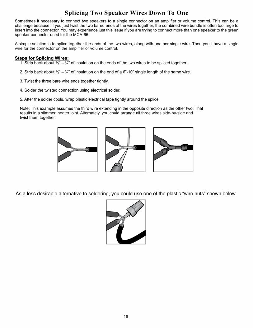
Sometimes it necessary to connect two speakers to a single connector on an amplifier or volume control. This can be a challenge because, if you just twist the two bared ends of the wires together, the combined wire bundle is often too large to insert into the connector. You may experience just this issue if you are trying to connect more than one speaker to the green speaker connector used for the MCA-66.
A simple solution is to splice together the ends of the two wires, along with another single wire. Then you’ll have a single wire for the connector on the amplifier or volume control.
Steps for Splicing Wires:1. Strip back about ½” – ¾” of insulation on the ends of the two wires to be spliced together.
2. Strip back about ½” – ¾” of insulation on the end of a 6”-10” single length of the same wire.
3. Twist the three bare wire ends together tightly.
4. Solder the twisted connection using electrical solder.
5. After the solder cools, wrap plastic electrical tape tightly around the splice.
Note: This example assumes the third wire extending in the opposite direction as the other two. Thatresults in a slimmer, neater joint. Alternately, you could arrange all three wires side-by-side andtwist them together.
Splicing Two Speaker Wires Down To One
As a less desirable alternative to soldering, you could use one of the plastic “wire nuts” shown below.

17
Connecting RJ-45 Plugs to Cat5e CablePlease use a standard (T-568A or T-568B) RJ-45 connection with Cat5e cable (regular Cat5, shielded Cat5, or Cat6 are all acceptable) to connect the keypad to the controller or another keypad. Never use a cable with a “Crossover” con-nection in which the two ends of the cable are wired differently.
When running your Cat5e cable, you have two options: 1) use cable of predetermined lengths that have the RJ-45 plugs attached by the manufacturer, or 2) use a crimping tool to attach the RJ-45 plugs yourself after you have run the Cat5e cable. With option 1) you don’t have to worry about the connections being solid and correct, but you’ll likely have to cut larger holes through the framework of your house to get the cables into position. This option will cost a little more because you are likely to have excess cable since you can only buy in predetermined lengths. Option 2) allows you to buy your Cat5e cable in bulk and run exactly the length you need for each connection. But you’ll have to terminate each end with an RJ-45 plug yourself.
Addendum
Instructions:Start on one end and strip the cable jacket off (about 1”) using a stripper or a knife. Be extra careful not to nick the wires, otherwise you will need to start over.
Spread, untwist the pairs, and arrange the wires in the order of the desired cable end. Flatten the end between your thumb and forefinger. Trim the ends of the wires so they are even with one another, leaving only 1/2” in wire length. If it is longer than 1/2” it will be out-of-spec and susceptible to crosstalk. Flatten and insure there are no spaces between wires.
Hold the RJ-45 plug with the clip facing down or away from you. Push the wires firmly into the plug. Inspect that each wire is flat and even at the front of the plug. Check the order of the wires. Double check again. Check that the jacket is fitted right against the stop of the plug. Carefully hold the wire and firmly crimp the RJ-45 with a special RJ-45 crimping tool.
Check the color orientation, check that the crimped connection is not about to come apart, and check to see if the wires are flat against the front of the plug. If even one of these are incorrect, you will have to start over.
We recommend use of our EZ-RJ45 Crimper Tool and our EZ-RJ45 Tips to make the this job MUCH easier. With the EZ-RJ45 system, the eight little wires of the Cat5 or Cat6 cable can be pulled completely through the EZ-RJ45 Tips, making color-coded wire verification easy.
Tips for Running Cat5e and Connecting to RJ-45:• If you are pulling cables through hole, it is easier to attach the RJ-45 plugs after the cable is pulled.• Odd numbered pins are always striped, even numbered pins are always solid colored. • Looking at the RJ-45 with the clip facing away from you, Brown is always on the right, and pin 1 is on the left. • No more than 1/2” of the Ethernet cable should be untwisted, otherwise it will be susceptible to crosstalk.• Do not deform, do not bend, do not stretch, do not staple, do not run parallel with power cables, and do not run Cat5e
cables near noise inducing components.
RJ-45 Plug
Clip is pointedaway from you T-568B
o O g B b G br BR
1 2 3 4 5 6 7 8
T-568Bo O g B b G br BR
1 2 3 4 5 6 7 8RJ-45 Plug
Clip is pointedaway from you T-568A
1 2 3 4 5 6 7 8
g G o B b O br BR
T-568A
1 2 3 4 5 6 7 8
g G o B b O br BR
Oo
Gg
Bb
BRbr
OrangeOrange striped
GreenGreen striped
BlueBlue striped
BrownBrown striped
Wire KeyT-568A Straight-Through Cat5e Cable T-568B Straight-Through Cat5e Cable
Pin 1Pin 1
Recommended
T-568A/T-568B Standardized RJ45 to Cat5e Connection Figure 13

Sharing Sources Across Multiple ControllersUp to 6 audio devices can be connected to each MC-66 controller. Every keypad attached to that controller can select between those devices. Using “Y-adapters”, it is possible to connect an audio device into multiple MC-66 controllers, making it available to all zones.
In the example below (Figure 12.1), the Tuner is available to all 12 zones, but Voice Assistant is only available to six zones and Streamer is only available to the other six zones.
18
Addendum
Sharing Sources Across Multiple Controllers Figure 14
Voice Assistant Tuner Streamer
Power
Multiroom Controller MC-66
Zone Status
1 2 3 4 5 6FU
SE T
1A/2
50V
AC 1
20V~
60H
zPo
wer
Con
sum
ptio
n: 7
0W
IR OUT IR IN
SOURCE INPUT
RS232 INTERFACE
KEYPAD PORTS
1 2 3 4 5 6
L
R
43
21
5 6
12V/DCTRIGGER
OUTIN
ZONE 1L R L R L R L R L RL R
ZONE 2 ZONE 3 ZONE 4 ZONE 5 ZONE 6
VAR
IAB
LE VA
RIA
BLE
FIXE
D
FIXED
Power
Multiroom Controller MC-66
Zone Status
1 2 3 4 5 6
FUSE
T1A
/250
V
AC 1
20V~
60H
zPo
wer
Con
sum
ptio
n: 7
0W
IR OUT IR IN
SOURCE INPUT
RS232 INTERFACE
KEYPAD PORTS
1 2 3 4 5 6
L
R
43
21
5 6
12V/DCTRIGGER
OUTIN
ZONE 1L R L R L R L R L RL R
ZONE 2 ZONE 3 ZONE 4 ZONE 5 ZONE 6
VAR
IAB
LE VA
RIA
BLE
FIXE
D
FIXED

Home Theater Direct, Inc.www.htd.com
Expert Support:Toll free: 866-HTD-AUDIO (483-2834)
TROUBLESHOOTING TIPS
• If you discover that a keypad is controlling a different zone, it is most likely because the speaker cables are connected to the wrong output of the amplifier.
• Protection Lights - the red protection lights on the MCA-66 will light only when a problem exists that triggers the built-in protection mode. The amplifier in a zone will shut down until the problem has been resolved. This is usually an indication of a short in the speaker cable or speaker connection.
If you have any questions, please contact HTD at [email protected] or toll free 1-866-HTD-AUDIO (483-2834).
Specifications:Stereo Zones
Stereo Inputs
Pre-amp outputs (switchable between Fixed and Variable) for each zone
RS232 connection for HTD MC App
IR emitter outputs
8 ohms RMS Watts Per Channel
4 ohms RMS Watts Per Channel
Dimensions (HxWxD)
Net Weight
MC-666
6
N/A
Y
3
N/A
N/A
4” x 17” x 8”
10 lbs.
MCA-666
6
Y
Y
3
20
30
4” x 17” x 17.5”
30 lbs.