Embed Size (px)
Citation preview

Whi
te P
aper
New Redundant Automatic Voltage Regulator (AVR) Solution
Author: David R. Brown, Turbomachinery Control Solutions Senior Consultant, Invensys Operations Management
What’s Inside:1. Introduction2. AVRFundamentals3. AddressingtheCurrent-SharingConfigurationChallenge4. AVRSolutionComponents5. TheAVRSolution’sMasterController6. DCCurrentDrives7. ACVoltageTransducer8. PowerSystemStabilizer(PSS)9. GeneratorMeasurementTransducers10.GeneratorExcitationCurrentandVoltageControl11.AVRSolutionFaultToleranceandOn-LineRepairability12.AVRSolutionCommissioning13.Conclusion14.References15.Bibliography
Page 1
1. IntroductionThis paper describes a redundant current-sharing generator solution that can be applied to generator sizes from 1MW to over 1000MW. Superior reliability, increased agility, on-line repair and continuous health are achieved by splitting the excitation current load between two current drivers, each of which is continuously diagnosed. Each current driver is sized for 100% duty and the backup driver can pick up the load and stabilize the system output within 8.3 milliseconds (or ½ cycle). The system includes a triple modular redundant (TMR) controller to integrate current driver management and generator control modes, features, and limits. The system architecture allows calibration, tuning, and thorough system tests before starting the prime mover and also allows the user to fully exploit the generator’s capability while still observing the manufacturer’s operating limits.
BackgroundTurbomachinery converts a flow of kinetic energy into mechanical power and generators convert that mechanical power into electrical power. Electrical power is produced by magnetic field excitation current and is controlled by a device historically known as the Automatic Voltage Regulator (AVR). The AVR controls the amount of generator excitation current - a change in excitation current will change the voltage output of the generator. Although traditional digital AVRs offer improved performance and automation features when compared to older analog AVRs, through more stable reactive power control and elimination of constant manual adjustments by the operator, they have two disadvantages - lower availability and higher machine stress. Typically, traditional AVRs may have a primary/backup arrangement to provide redundant excitation current drives. In this arrangement, only one current drive operates at a time and if there is a fault with the first current drive, the backup current drive takes over control — without knowing its health — and the operating drive can be over-stressed.
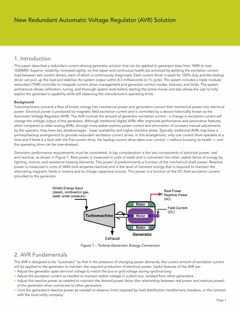
Generator performance requirements must be considered. A key consideration is the two components of electrical power: real and reactive, as shown in Figure 1. Real power is measured in units of watts and is converted into other usable forms of energy by lighting, motors, and resistance heating elements. This power is predominantly a function of the mechanical shaft power. Reactive power is measured in units of VARs (volt-amperes reactive) and is the level of transient energy that is required to maintain the alternating magnetic fields in motors and to charge capacitive circuits. This power is a function of the DC field excitation current provided to the generator.
Figure 1 – Turbine-Generator Energy Conversion
2. AVR FundamentalsThe AVR is designed to be “automatic” so that in the presence of changing power demands, the correct amount of excitation current will be applied to the generator to maintain the required production of electrical power. Useful features of the AVR are:• Adjust the generator open terminal voltage to match the bus or grid voltage during synchronizing• Adjust the excitation current as needed to maintain stable voltage in a plant bus, isolated from other generators• Adjust the reactive power as needed to maintain the desired power factor (the relationship between real power and reactive power)
of the generator when connected to other generators• Limit the generator’s reactive power as needed to observe limits imposed by load distribution transformers, breakers, or the contract
with the local utility company
New Redundant Automatic Voltage Regulator (AVR) Solution

Page 2
• Adjust the generator’s excitation current as needed to observe the generator manufacturer’s heat capacity limits to prevent overheating of either the generator stator or rotor
• Limit the generator’s excitation current as needed to observe the generator manufacturer’s over and under excitation limits
3. Addressing the Current-Sharing Configuration ChallengeAlthough current-sharing is preferred, there are some technical hurdles that must be overcome to allow redundant, load sharing configuration of two current drives. A typical current drive is powered by three-phase alternating current (AC) and uses a bridge of six thyristors to produce the direct current (DC) output required by the generator exciter field. Thyristors conduct directional current when triggered in the presence of a minimum forward gate voltage. Simply connecting two current drives in parallel would not allow both drives to smoothly contribute an equal amount of DC current. The corresponding thyristors from each drive would attempt to fire at the same time. The moment that one thyristor begins conducting current, the voltage difference across the corresponding thyristor in the other drive drops below the minimum forward gate voltage, preventing it from conducting.
A solution to the redundant thyristor firing issue is to shift the three-phase feed of one of the current drives by 30°. This is accomplished by utilizing a delta-wye transformer to feed one current drive and a delta-delta transformer to feed the other current drive, as shown in Figure 2. Both types of industrial transformers are commonly available. The relative phase shift of the two feeds ensures that a minimum forward gate voltage is present when each of the corresponding thyristors is triggered.
Figure 2 – Transformer Phase-Shifted Power Feed
The thyristor bridge in each drive will fire to provide an output pulse every 60° for each phase, producing rectified DC output from the drive. The total DC current output of the drive is controlled by the firing angle of the thyristors and the earlier that the thyristors fire in the AC waveform cycle, the more current is produced. By utilizing the phase shifting transformer arrangement, the two drives together produce an output pulse every 30°, resulting in a smoother DC output from two drives than from a single drive. For a 60Hz generator, the redundant drives provide a DC output at 720Hz with less ripple than a single drive.
By implementing a relative phase shift in the power feeds of the DC drives, they can both simultaneously control current.
New Redundant Automatic Voltage Regulator (AVR) Solution

Page 3
4. AVR Solution ComponentsThe generator excitation solution described in this paper is the result of over 75 redundant generator control systems provided to customers since 1994. The specific configuration described in this paper was first applied on two 60MW gas turbine generator units in 2003. The major system components are shown in Figure 3.
Figure 3 – System Components
5. The AVR Solution’s Master ControllerA highly reliable triple modular redundant (TMR) logic solver is used as the Master Controller. The TMR platform was originally developed for critical control and emergency shutdown (ESD) functions in the process industries where safety availability (system always takes appro-priate action when required) and reliability (system does not cause spurious process trips) are both very important to the end user.
The Master Controller gathers various measurements from the generator and performs generator supervisory control in the application program. Several communication modules are available for the Master Controller to provide serial, Ethernet, and native interfaces to practically any human machine interface (HMI) or distributed control system (DCS) that the end user chooses.
The following is a list of typical generator control, limiting, and monitoring functions that are provided by the Master Controller.• Over Excitation Limits - Hard over-excitation limit, timed based over-excitation limit, off-line maximum excitation limit, “V” curve-
based maximum excitation limit• Minimum Excitation Limits - “V” curve-based minimum excitation limit, on-line minimum excitation limit• Voltage Control - Volts-per-hertz limit, system will tolerate the loss of voltage sensing (PT fuses)• Automatic Bus Voltage Matching - Automatic synchronizing / generator breaker closing feature. Note: the automatic synchronizing
feature can easily be added for as many distribution bus breakers as are needed for each application.• Transformer Secondary Voltage Control - For applications where the generator outputs through a transformer• VAR Control - This allows the generator output to be manipulated to maintain a target VAR setpoint• Power Factor (PF) Control - This is accomplished as a special case of VAR control. The PF setpoint and watt measurement are used
to calculate a VAR setpoint. This PF control variation is not a PF meter measurement based control.
New Redundant Automatic Voltage Regulator (AVR) Solution

Page 4
New Redundant Automatic Voltage Regulator (AVR) Solution
• Utility Power Factor (PF) Control - This is accomplished as a special case of utility VAR control. The PF setpoint and watt measurement are used to calculate a VAR setpoint. This PF control variation is not a PF meter measurement based control.
• Prioritized Temperature Limiting - Calculated rotor temperature limit and stator temperature limit• Automatic Transformer Tap Change Control and Coordination - For applications where the utility transformer has a tap changing feature• Utility VAR Control - This allows the generator output to be manipulated to maintain a target utility VAR setpoint• Multiple Generator Voltage and VAR Load Sharing Coordination - Load sharing can be accomplished by sharing data between
generator excitation control systems over peer-to-peer communication networks
In addition to generator-related control functions, the Master Controller executes turbine protection functions, turbine and auxiliary equipment sequencing, offline speed control, online load control and turbine valve management functions. By integrating turbine and generator control functions into a single logic solver, tighter control of the entire turbine-generator train is achieved while eliminating the need to train personnel and stock spare parts for separate control systems.
6. DC Current DrivesThe DC current drives used in the generator excitation system were originally designed for control of DC motors. The DC drive is available “off the shelf” with current outputs from 35 to 2400 amps in order to meet the requirements of any type of generator exciter. DC drive configurations can be provided for generator sizes ranging from 1MW to over 1000MW. The DC drives are three-phase, full wave thyristor bridges as shown in IEEE 421.1-19861.[1] A special software and hardware configuration of the drive was developed for generator excitation current drive applications. This DC current drive operates with a 2.7 milliseconds loop cycle time and also includes a fast bipolar analog input to accept the bias control signal from a power system stabilizer (PSS).
7. AC Voltage TransducerCommercially available AC voltage transducers typically have response times greater than 100 milliseconds, which is too slow for voltage control. The AC voltage transducer utilized in this application is a specially designed circuit that provides three-phase, full wave rectification of the signal from the open-delta instrument potential transformer (PT). The rectified signal is passed through a low frequency pass filter to eliminate high frequency noise. The DC output signal of the voltage transducer is connected to the measurement of the DC drive. Throughput transient response of the transducer is 8 milliseconds. One voltage transducer is provided for each DC drive.
8. Power System Stabilizer (PSS)A PSS is recommended by the North American Electric Reliability Council (NERC) for all mid-size and larger generators. A commercially available PSS unit is utilized with the generator excitation system. The purpose of the PSS is to detect and stabilize resonant power fluctuations between large power generation systems. When power fluctuations within the range of 0.1 – 3 Hz are detected, the PSS generates a sinusoidal control signal that the DC drive and Master Controller use to create a correlating bias on the excitation current output to help dampen the power fluctuations.
9. Generator Measurement TransducersSeveral signal transducers are used for synchronizing, operating mode management, and monitoring. These include:• Generator Phase-to-Phase Voltages (AB, BC, CA)• Bus Phase-to-Phase Voltage (AB)• Generator Phase Current (A, B, C)• Generator Watts• Generator VARs• Generator-Bus Synchronizing Phase Angle
10. Generator Excitation Current and Voltage ControlThere are two traditional control modes provided by modern AVRs: Manual and Automatic. In Manual mode, the operator manually adjusts excitation current in an open loop manner. In Automatic mode, the operator selects a generator terminal voltage setpoint and a Proportional Integral Derivative (PID) control loop automatically manipulates the excitation current to achieve the desired voltage.

Page 5
New Redundant Automatic Voltage Regulator (AVR) Solution
Figure 4 – Excitation Current and Generator Voltage Control Diagram
In this generator excitation system, both drives are normally active with an excitation current PID control loop active in each drive. In Manual mode the operator selects the setpoint for the excitation current output. This setpoint is divided equally between the two drives. As shown in Figure 4, the DC current flow feedback measurement signal is produced with AC current transformer (CT) sensors that are placed on the three-phase AC input feed side of the current drive. The combined output of the two DC drives is the DC current supplied to the exciter field coil.
In Automatic mode, voltage control functions are distributed between the two DC drives and the Master Controller. A proportional-only voltage PID control loop resides in each DC drive. The output of the voltage PID control loop is the excitation current PID loop setpoint. Interaction between the cascaded voltage and current control loops in the drives is coordinated so that control mode transitions are handled smoothly without causing disturbances to the connected electrical system.
Figure 5 – Generator Voltage Droop Graph

Page 6
New Redundant Automatic Voltage Regulator (AVR) Solution
Normally both DC drives operate together. The voltage PID control loop in each drive receives a voltage setpoint from the Master Controller. Since the voltage PID control loops in each drive operate with only proportional action, the two drives will operate together in a voltage droop mode to proportionally share the load as shown in Figure 5. If voltage decreases, each drive will proportionally increase its respective contribution to the total excitation current. Because of the fast loop cycle time, the drives will detect voltage disturbances and adjust their outputs proportionally in ½ cycle (8.3 milliseconds). This configuration provides generator terminal voltage droop based on exciter field current.
Since the drives operate in voltage droop (proportional) mode, load changes will cause small transient differences between the voltage setpoint and measurement. On a 13.8kV electrical system and a typical droop setting of 3% for each drive, the maximum voltage offset is 414 volts. The integral action in the Master Controller’s voltage PID control loop will adjust the voltage setpoints of each drive to return the steady state offset between the Master Controller voltage setpoint and voltage measurement to zero.
Status information is communicated directly between the two drives with discrete inputs and outputs. When both drives are active, each drive’s maximum current limit is switched from 100.0 % to 50.0 %. Also, the proportional gain (droop) of each drive is doubled. These actions allow the two drives to share the total load with a net droop setting that is the same for one drive operating alone.
Each DC drive is capable of applying large positive and negative voltages to the exciter field in order to effect fast current changes to meet fast demands for increases or decreases in reactive power.
11. AVR Solution Fault Tolerance and On-Line RepairabilityThe generator excitation system is designed so that the failure of any single component will not cause the generator to trip or cause any control degradation. Such redundancy may be justified if a spurious trip of the generator can result in unsafe operation of the plant or cause financially significant production losses. Any component failure will generate an alarm in the HMI to alert the operator of the fault.
The TMR Master Controller can tolerate any single fault and even certain multiple faults without interrupting any control functions. The TMR Master Controller can also accept two separate power feeds. Many options are available, including one AC and one DC feed or two AC feeds from separate sources.
Since the DC excitation current drives are redundant, if one drive fails, the other drive will continue to provide all required excitation current. Each DC drive can be powered by separate AC power feeds.
All generator and exciter measurements that are critical to maintaining control are made redundant so that the failure of a single measurement will not prevent normal operation of the generator.
To take full advantage of component fault tolerance, the end user should be able to replace faulted components while the generator is operating at any load. PT isolation fuses and power disconnects are all provided to allow on-line replacement of each drive or measuring instrument. Any power, processor, input/output, or communication module in the TMR Master Controller can be replaced on-line.
12. AVR Solution CommissioningWhen auxiliary power is available, the DC drives can be functionally tested and the current PID control loops tuned for each drive individually and as a redundant current-sharing set, without requiring operation of the turbine. For brushless type exciters, this can be accomplished with the generator rotor at rest. However, to prevent welding of the brushes to the slip rings for brush type exciters, a minimum continuous motion of the rotor is necessary and can be provided by either the turning gear or by slow rolling the turbine rotor assembly.
Full rated excitation current functional testing can be completed without the risk of creating high generator output voltage levels when the rotor speed is kept at a low level, because the voltage produced is proportional to rotor speed.
Tuning without operating the turbine saves energy at commissioning because the turbine does not need to be started. This can also save time during commissioning since the excitation current PID loops can be tuned while mechanical work on the turbine and other related equipment is still in progress.

Page 7
New Redundant Automatic Voltage Regulator (AVR) Solution
13. ConclusionThe generator excitation solution described in this paper provides redundant current sharing with a unique method that has already provided more than 27,000 operating hours of reliable performance. The complete system is redundant so that component failures can be tolerated and faulty parts replaced while the generator is operating at any load. The generator excitation solution provides very fast generator terminal voltage control in the presence of transient loads.
14. References[1] ANSI/IEEE Std 421.1-1986, “IEEE Standard Definitions for Excitation Systems for Synchronous Machines,” 1986, page 15, Figure 15B.
15. Bibliography15th Annual Joint ISA POWID/EPRI Controls & Instrumentation Conference, ISA_POW05-P015.
Invensys, the Invensys logo, ArchestrA, Avantis, Eurotherm, Foxboro, IMServ, InFusion, SimSci-Esscor, Skelta, Triconex, and Wonderware are trademarks of Invensys plc, its subsidiaries or affiliates. All other brands and product names may be the trademarks or service marks of their representative owners.
© 2010 Invensys Systems, Inc. All rights reserved. No part of the material protected by this copyright may be reproduced or utilized in any form or by any means, electronic or mechanical, including photocopying, recording, broadcasting, or by any information storage and retrieval system, without permission in writing from Invensys Systems, Inc.
Invensys Operations Management • 5601 Granite Parkway III, #1000, Plano, TX 75024 • Tel: (469) 365-6400 • Fax: (469) 365-6401 • iom.invensys.com
Rel. 08/10 PN IN-0120