Embed Size (px)
Citation preview
Jan Kremer Consulting Services (JKCS)
Data Center Design White Paper Page 1
DATA CENTER DESIGN
White Paper
JJAANN KKRREEMMEERR
CCOONNSSUULLTTIINNGG SSEERRVVIICCEESS
Jan Kremer Consulting Services (JKCS)
Data Center Design White Paper Page 2
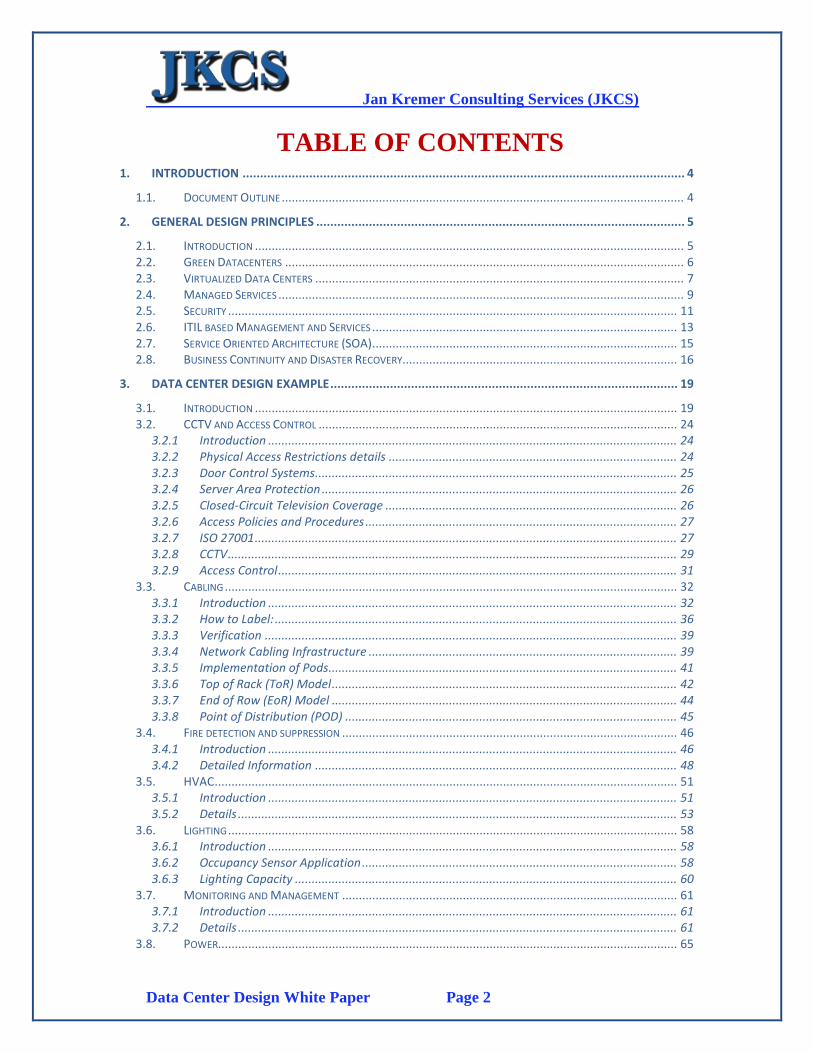
TABLE OF CONTENTS 1. INTRODUCTION .............................................................................................................................. 4
1.1. DOCUMENT OUTLINE ........................................................................................................................ 4
2. GENERAL DESIGN PRINCIPLES ......................................................................................................... 5
2.1. INTRODUCTION ................................................................................................................................ 5 2.2. GREEN DATACENTERS ....................................................................................................................... 6 2.3. VIRTUALIZED DATA CENTERS .............................................................................................................. 7 2.4. MANAGED SERVICES ......................................................................................................................... 9 2.5. SECURITY ...................................................................................................................................... 11 2.6. ITIL BASED MANAGEMENT AND SERVICES ........................................................................................... 13 2.7. SERVICE ORIENTED ARCHITECTURE (SOA) ........................................................................................... 15 2.8. BUSINESS CONTINUITY AND DISASTER RECOVERY.................................................................................. 16
3. DATA CENTER DESIGN EXAMPLE ................................................................................................... 19
3.1. INTRODUCTION .............................................................................................................................. 19 3.2. CCTV AND ACCESS CONTROL ........................................................................................................... 24
3.2.1 Introduction .......................................................................................................................... 24 3.2.2 Physical Access Restrictions details ...................................................................................... 24 3.2.3 Door Control Systems............................................................................................................ 25 3.2.4 Server Area Protection .......................................................................................................... 26 3.2.5 Closed-Circuit Television Coverage ....................................................................................... 26 3.2.6 Access Policies and Procedures ............................................................................................. 27 3.2.7 ISO 27001 .............................................................................................................................. 27 3.2.8 CCTV ...................................................................................................................................... 29 3.2.9 Access Control ....................................................................................................................... 31
3.3. CABLING ....................................................................................................................................... 32 3.3.1 Introduction .......................................................................................................................... 32 3.3.2 How to Label: ........................................................................................................................ 36 3.3.3 Verification ........................................................................................................................... 39 3.3.4 Network Cabling Infrastructure ............................................................................................ 39 3.3.5 Implementation of Pods........................................................................................................ 41 3.3.6 Top of Rack (ToR) Model ....................................................................................................... 42 3.3.7 End of Row (EoR) Model ....................................................................................................... 44 3.3.8 Point of Distribution (POD) ................................................................................................... 45
3.4. FIRE DETECTION AND SUPPRESSION .................................................................................................... 46 3.4.1 Introduction .......................................................................................................................... 46 3.4.2 Detailed Information ............................................................................................................ 48
3.5. HVAC .......................................................................................................................................... 51 3.5.1 Introduction .......................................................................................................................... 51 3.5.2 Details ................................................................................................................................... 53
3.6. LIGHTING ...................................................................................................................................... 58 3.6.1 Introduction .......................................................................................................................... 58 3.6.2 Occupancy Sensor Application .............................................................................................. 58 3.6.3 Lighting Capacity .................................................................................................................. 60
3.7. MONITORING AND MANAGEMENT .................................................................................................... 61 3.7.1 Introduction .......................................................................................................................... 61 3.7.2 Details ................................................................................................................................... 61
3.8. POWER......................................................................................................................................... 65
Jan Kremer Consulting Services (JKCS)
Data Center Design White Paper Page 3
3.8.1 Introduction .......................................................................................................................... 65 3.8.2 Power Design Includes: ......................................................................................................... 65 3.8.3 Details ................................................................................................................................... 68
3.9. RACKS .......................................................................................................................................... 71 3.9.1 Introduction .......................................................................................................................... 71 3.9.2 Details ................................................................................................................................... 71
3.10. RAISED FLOOR ............................................................................................................................... 72 3.10.1 Introduction ..................................................................................................................... 72 3.10.2 Summary .......................................................................................................................... 75
3.11. RF SHIELDING ................................................................................................................................ 76 3.11.1 Introduction ..................................................................................................................... 76 3.11.2 Details .............................................................................................................................. 76
3.12. WATER DETECTION ......................................................................................................................... 77 3.12.1 Introduction ..................................................................................................................... 77 3.12.2 Details .............................................................................................................................. 77 3.12.3 Tracetek from Tyco Thermal Controls .............................................................................. 83
3.13. LABELING ...................................................................................................................................... 86 3.13.1 Introduction ..................................................................................................................... 86 3.13.2 Features ........................................................................................................................... 86 3.13.3 Benefits ............................................................................................................................ 87 3.13.4 Provides ............................................................................................................................ 87
Jan Kremer Consulting Services (JKCS)
Data Center Design White Paper Page 4
1. INTRODUCTION
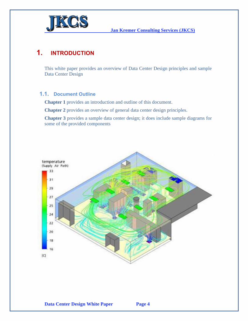
This white paper provides an overview of Data Center Design principles and sample
Data Center Design
1.1. Document Outline
Chapter 1 provides an introduction and outline of this document.
Chapter 2 provides an overview of general data center design principles.
Chapter 3 provides a sample data center design; it does include sample diagrams for
some of the provided components
Jan Kremer Consulting Services (JKCS)
Data Center Design White Paper Page 5
2. General Design Principles
2.1. Introduction
Knowing what the client needs are the essentials of good data center design, and the
general infrastructure that a data center includes are the basic starting principles.
Now we need to concentrate on its exact scope. How many layers of infrastructure
should the data center include, will it be only server environment for one or many
managed services capabilities, how does the main data center purpose relate to the
disaster recovery data center
capabilities as to scope, capabilities
and service levels and what kind of
tier level is required etc.
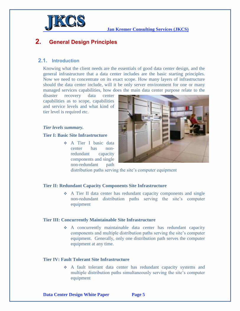
Tier levels summary.
Tier I: Basic Site Infrastructure
A Tier I basic data
center has non-
redundant capacity
components and single
non-redundant path
distribution paths serving the site’s computer equipment
Tier II: Redundant Capacity Components Site Infrastructure
A Tier II data center has redundant capacity components and single
non-redundant distribution paths serving the site’s computer
equipment
Tier III: Concurrently Maintainable Site Infrastructure
A concurrently maintainable data center has redundant capacity
components and multiple distribution paths serving the site’s computer
equipment. Generally, only one distribution path serves the computer
equipment at any time.
Tier IV: Fault Tolerant Site Infrastructure
A fault tolerant data center has redundant capacity systems and
multiple distribution paths simultaneously serving the site’s computer
equipment
Jan Kremer Consulting Services (JKCS)
Data Center Design White Paper Page 6
2.2. Green Datacenters
Data center cooling is where the greatest energy-efficiency improvements can be
made. And cooling a data center efficiently is impossible without proper floor plan
and air-conditioning design. The fundamental rule in energy- efficient cooling is to
keep hot air and cold air separate. The hot-aisle/cold aisle, raised-floor design has
been the cooling standard for many years, yet surprisingly few data centers
implement this principle fully or correctly.
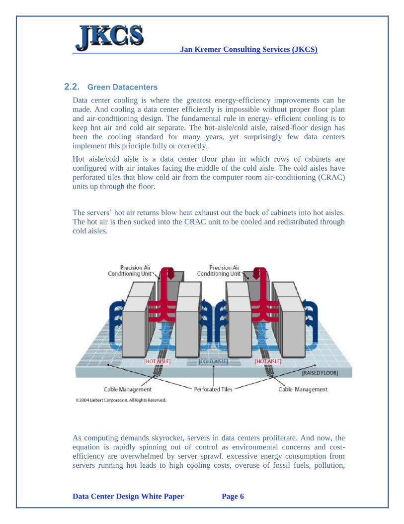
Hot aisle/cold aisle is a data center floor plan in which rows of cabinets are
configured with air intakes facing the middle of the cold aisle. The cold aisles have
perforated tiles that blow cold air from the computer room air-conditioning (CRAC)
units up through the floor.
The servers’ hot air returns blow heat exhaust out the back of cabinets into hot aisles.
The hot air is then sucked into the CRAC unit to be cooled and redistributed through
cold aisles.
As computing demands skyrocket, servers in data centers proliferate. And now, the
equation is rapidly spinning out of control as environmental concerns and cost-
efficiency are overwhelmed by server sprawl. excessive energy consumption from
servers running hot leads to high cooling costs, overuse of fossil fuels, pollution,
Jan Kremer Consulting Services (JKCS)
Data Center Design White Paper Page 7
depletion of natural resources and release of harmful co2 as waste. For every kilowatt
of energy consumed by a server, roughly another kilowatt must be expended to cool
that machine. By the end of 2008, the power costs of a server have exceeded the cost
of the server itself. Reduction of the number of servers can be achieved by
implementing a “Virtualized Data Center”. Using less equipment to do more goes to
the heart of being LEAN & GREEN. Consolidating and virtualizing storage and
using efficient computing practices and power-saving tactics are the route to
achieving environmental efficiency and reduction of cost.
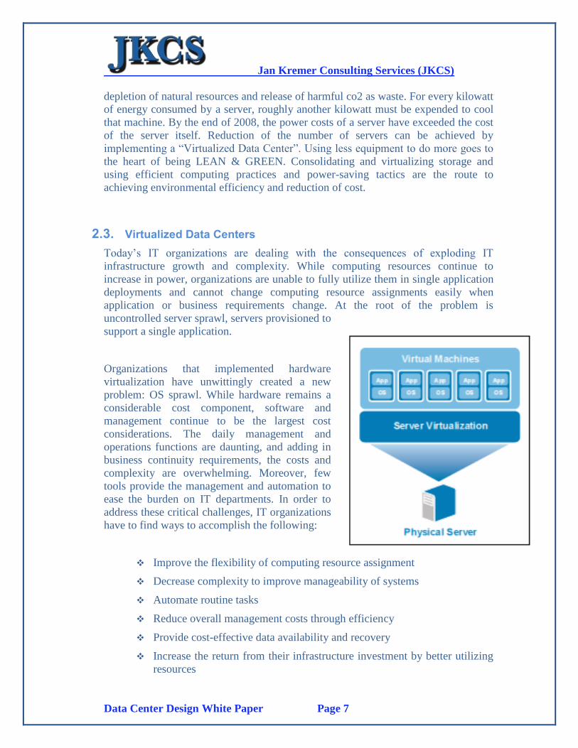
2.3. Virtualized Data Centers
Today’s IT organizations are dealing with the consequences of exploding IT
infrastructure growth and complexity. While computing resources continue to
increase in power, organizations are unable to fully utilize them in single application
deployments and cannot change computing resource assignments easily when
application or business requirements change. At the root of the problem is
uncontrolled server sprawl, servers provisioned to
support a single application.
Organizations that implemented hardware
virtualization have unwittingly created a new
problem: OS sprawl. While hardware remains a
considerable cost component, software and
management continue to be the largest cost
considerations. The daily management and
operations functions are daunting, and adding in
business continuity requirements, the costs and
complexity are overwhelming. Moreover, few
tools provide the management and automation to
ease the burden on IT departments. In order to
address these critical challenges, IT organizations
have to find ways to accomplish the following:
Improve the flexibility of computing resource assignment
Decrease complexity to improve manageability of systems
Automate routine tasks
Reduce overall management costs through efficiency
Provide cost-effective data availability and recovery
Increase the return from their infrastructure investment by better utilizing
resources
Jan Kremer Consulting Services (JKCS)
Data Center Design White Paper Page 8
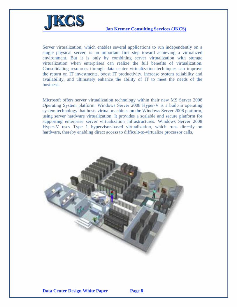
Server virtualization, which enables several applications to run independently on a
single physical server, is an important first step toward achieving a virtualized
environment. But it is only by combining server virtualization with storage
virtualization when enterprises can realize the full benefits of virtualization.
Consolidating resources through data center virtualization techniques can improve
the return on IT investments, boost IT productivity, increase system reliability and
availability, and ultimately enhance the ability of IT to meet the needs of the
business.
Microsoft offers server virtualization technology within their new MS Server 2008
Operating System platform. Windows Server 2008 Hyper-V is a built-in operating
system technology that hosts virtual machines on the Windows Server 2008 platform,
using server hardware virtualization. It provides a scalable and secure platform for
supporting enterprise server virtualization infrastructures. Windows Server 2008
Hyper-V uses Type 1 hypervisor-based virtualization, which runs directly on
hardware, thereby enabling direct access to difficult-to-virtualize processor calls.
Jan Kremer Consulting Services (JKCS)
Data Center Design White Paper Page 9
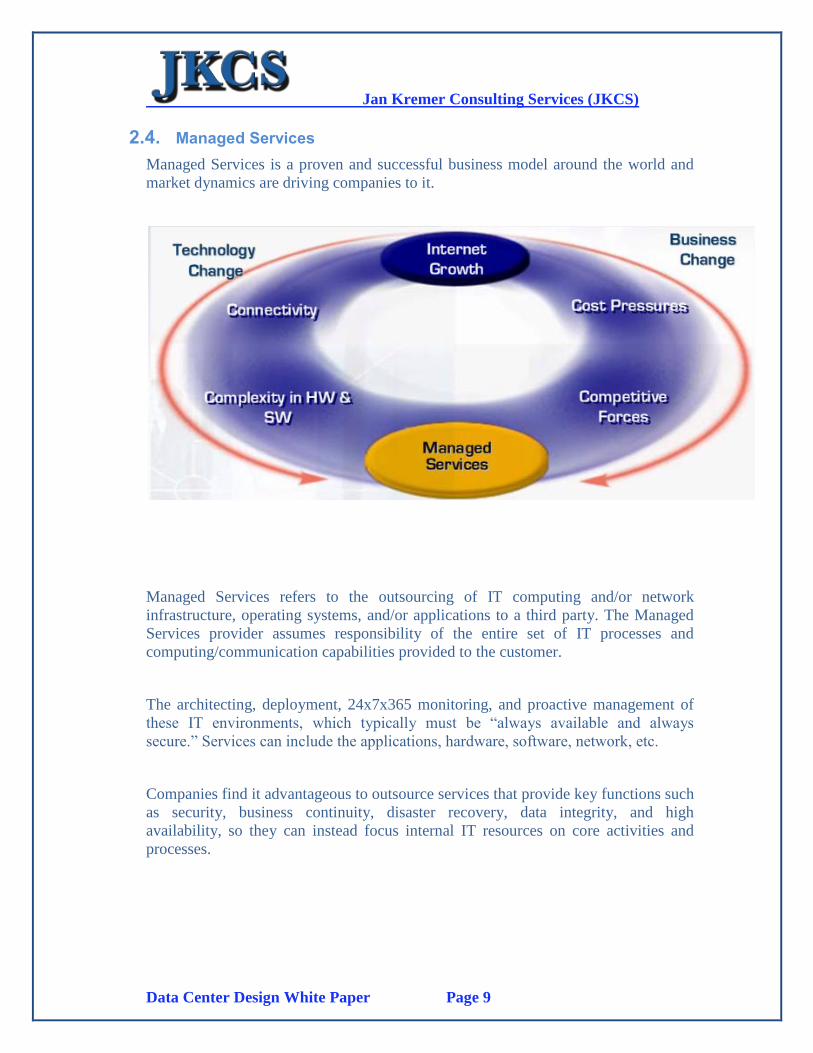
2.4. Managed Services
Managed Services is a proven and successful business model around the world and
market dynamics are driving companies to it.
Managed Services refers to the outsourcing of IT computing and/or network
infrastructure, operating systems, and/or applications to a third party. The Managed
Services provider assumes responsibility of the entire set of IT processes and
computing/communication capabilities provided to the customer.
The architecting, deployment, 24x7x365 monitoring, and proactive management of
these IT environments, which typically must be “always available and always
secure.” Services can include the applications, hardware, software, network, etc.
Companies find it advantageous to outsource services that provide key functions such
as security, business continuity, disaster recovery, data integrity, and high
availability, so they can instead focus internal IT resources on core activities and
processes.
Jan Kremer Consulting Services (JKCS)
Data Center Design White Paper Page 10
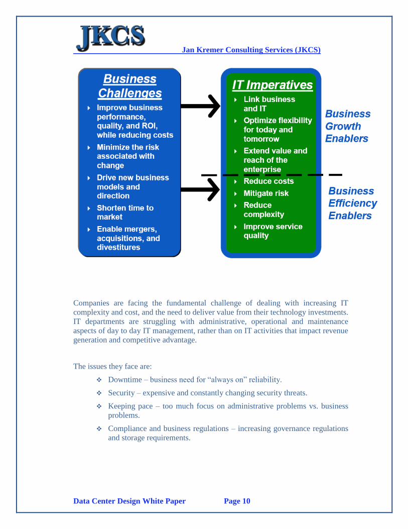
Companies are facing the fundamental challenge of dealing with increasing IT
complexity and cost, and the need to deliver value from their technology investments.
IT departments are struggling with administrative, operational and maintenance
aspects of day to day IT management, rather than on IT activities that impact revenue
generation and competitive advantage.
The issues they face are:
Downtime – business need for “always on” reliability.
Security – expensive and constantly changing security threats.
Keeping pace – too much focus on administrative problems vs. business
problems.
Compliance and business regulations – increasing governance regulations
and storage requirements.
Jan Kremer Consulting Services (JKCS)
Data Center Design White Paper Page 11
2.5. Security
The increasing multiplicity of data centre locations and often the geographical
dispersion of IT administrators increases the importance of a sound security strategy.
To work effectively, the strategy should establish guidelines and responsibilities to
protect the information assets of a company.
Physical security
Public: areas that all employees can access
Controlled: areas that can and must be locked when unattended
Very controlled: areas where access is restricted to registered or authorized users
The question for many IT managers is how to supplement physical security strategy.
The answer is to give secure, remote access and control of data centre servers and
devices to authorized personnel no matter where they or the devices are located.
Data Center physical security includes components such as:
CCTV System with central control room monitors and video recording
units\
Data Center Access Control System with role based access control for the
different zones and rooms within the Data Center including biometrics
fingerprint scanners (employees only)
Visitor “temporary” card issuance system for Data Center access for
visitors
Employee Access Card Issuance system with Digital Camera (capturing
digital photo for card surface) and Biometrics Fingerprint Scanner
(Fingerprint minutiae on card contactless chip for 1-1 verification at
access points). Additional Biometrics systems such as Iris and facial
recognition are also supported
Outside CCTV cameras for Data Center perimeter security management
The security systems can utilize the existing IP network for functionality for both
access control requests and CCTV. This reduces the cost and complexity of adding
separate physical lines. Additionally, it will allow for remote monitoring and
management from any Facility.
Logical security
Logical security strategy requires the IT manager to identify and authenticate users.
User IDs need to be established to identify the person connecting to the system.
Logical security includes defining and protecting resources. What resources can users
access when they have been authenticated?

Jan Kremer Consulting Services (JKCS)
Data Center Design White Paper Page 12
Physical and Logical Security Convergence
"CEOs and boards don't really think about security; they think about risk. With too
many security discussions, they kind of glaze over the issue, but when you're talking
with executive management and explaining things to them in terms of risk to the
business, that really gets the business leaders thinking about integration and
convergence of physical security and IT security in the right way."
— Practice Leader, Global IT Services Provider
Convergence of logical and physical security brings significant benefits, specifically
identifying areas where the two can interconnect to the greatest positive effect. In
order to make this convergence happen, security management must be integrated
with existing business processes for managing facilities, personnel and IT Systems.
This requires clear organizational ownership on critical management processes such
as:
Enterprise Security Policy
User provisioning and asset management
Security monitoring and auditing
Incident response
Business Continuity Planning
One simple example of this convergence is the usage of a smartcard based Identity
Card which is used for Physical Access Control as well as for authentication of the
cardholder to computers and data. This Smartcard based ID card is based on a combi-
chip, meaning the card has one chip which supports contact (Logical Security for
Computer Authentication with biometrics based identity verification) and a
contactless proximity chip (Physical Security used for access control using the same
biometrics as provided by the contact portion of the chip)

Jan Kremer Consulting Services (JKCS)
Data Center Design White Paper Page 13
2.6. ITIL based Management and Services
The IT Infrastructure Library (ITIL), a set of best practices addressing the delivery of
high-quality, cost-effective IT services, includes best practice guidelines for multiple
IT Operations activities. Release Management and Change Management are two
activities within ITIL’s IT Service Management (ITSM) disciplines that offer
guidance for deploying changes to IT services. Both Release and Change
Management recommend pre-deployment testing, and best practice guidance sug-
gests that improving these processes also benefits ITSM Incident, Problem, and
Availability Management.
Benefits of ITIL deployment
The key benefits of implementing ITIL:
Improving IT and business alignment
Improved productivity
Ensuring best practice
Implementation of ITIL can be costly, so where can an organization expect to recover
those costs?
Jan Kremer Consulting Services (JKCS)
Data Center Design White Paper Page 14
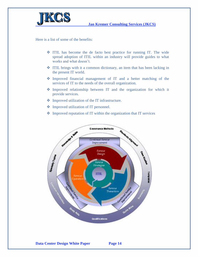
Here is a list of some of the benefits:
ITIL has become the de facto best practice for running IT. The wide
spread adoption of ITIL within an industry will provide guides to what
works and what doesn’t.
ITIL brings with it a common dictionary, an item that has been lacking in
the present IT world.
Improved financial management of IT and a better matching of the
services of IT to the needs of the overall organization.
Improved relationship between IT and the organization for which it
provide services.
Improved utilization of the IT infrastructure.
Improved utilization of IT personnel.
Improved reputation of IT within the organization that IT services
Jan Kremer Consulting Services (JKCS)
Data Center Design White Paper Page 15
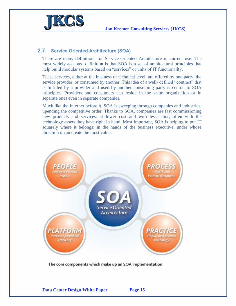
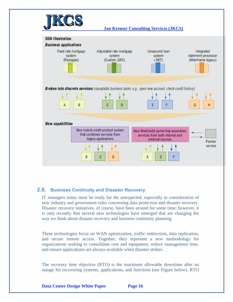
2.7. Service Oriented Architecture (SOA)
There are many definitions for Service-Oriented Architecture in current use. The
most widely accepted definition is that SOA is a set of architectural principles that
help build modular systems based on “services” or units of IT functionality.
These services, either at the business or technical level, are offered by one party, the
service provider, or consumed by another. This idea of a well- defined “contract” that
is fulfilled by a provider and used by another consuming party is central to SOA
principles. Providers and consumers can reside in the same organization or in
separate ones even in separate companies.
Much like the Internet before it, SOA is sweeping through companies and industries,
upending the competitive order. Thanks to SOA, companies are fast commissioning
new products and services, at lower cost and with less labor, often with the
technology assets they have right in hand. Most important, SOA is helping to put IT
squarely where it belongs: in the hands of the business executive, under whose
direction it can create the most value.
Jan Kremer Consulting Services (JKCS)
Data Center Design White Paper Page 16
2.8. Business Continuity and Disaster Recovery
IT managers today must be ready for the unexpected, especially in consideration of
new industry and government rules concerning data protection and disaster recovery.
Disaster recovery initiatives, of course, have been around for some time; however, it
is only recently that several new technologies have emerged that are changing the
way we think about disaster recovery and business continuity planning.
These technologies focus on WAN optimization, traffic redirection, data replication,
and secure remote access. Together, they represent a new methodology for
organizations seeking to consolidate cost and equipment, reduce management time,
and ensure applications are always available when disaster strikes.
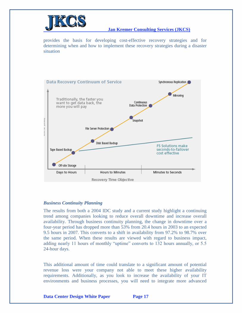
The recovery time objective (RTO) is the maximum allowable downtime after an
outage for recovering systems, applications, and functions (see Figure below). RTO
Jan Kremer Consulting Services (JKCS)
Data Center Design White Paper Page 17
provides the basis for developing cost-effective recovery strategies and for
determining when and how to implement these recovery strategies during a disaster
situation
Business Continuity Planning
The results from both a 2004 IDC study and a current study highlight a continuing
trend among companies looking to reduce overall downtime and increase overall
availability. Through business continuity planning, the change in downtime over a
four-year period has dropped more than 53% from 20.4 hours in 2003 to an expected
9.5 hours in 2007. This converts to a shift in availability from 97.2% to 98.7% over
the same period. When these results are viewed with regard to business impact,
adding nearly 11 hours of monthly “uptime” converts to 132 hours annually, or 5.5
24-hour days.
This additional amount of time could translate to a significant amount of potential
revenue loss were your company not able to meet these higher availability
requirements. Additionally, as you look to increase the availability of your IT
environments and business processes, you will need to integrate more advanced
Jan Kremer Consulting Services (JKCS)
Data Center Design White Paper Page 18
means of achieving these results. The impact of reaching these high-availability goals
will likely require greater levels of expertise, automation, and, ultimately, capital
investment.
Disaster Recovery Planning
A Disaster Recovery Plan covers the data, hardware and software critical for a
business to restart operations in the event of a natural or human-caused disaster. It
should also include plans for coping with the unexpected or sudden loss of key
personnel. The analysis phase in the development of a BCP (Business Continuity
Plan) manual consists of an impact analysis, threat analysis, and impact scenarios
with the resulting BCP plan requirement documentation.
Jan Kremer Consulting Services (JKCS)
Data Center Design White Paper Page 19
3. Data Center Design Example
3.1. Introduction
This section provides Data Center Design examples for the following components
This document represents the second deliverable for this project which is a “Low
Level” design for the main components of the Data Center such as:
General Design
o Floor Plan
o Final layout for the Communications Room and Power Distribution Room
o Labeling and Mapping
o Shielding
Power System Design
o Final Design for the Generator Sets
o Final Floor Plans for the Generator Sets room
o Final Design for the UPS systems
o Overhead power cabling since water piping is under raised floor
Cooling/AC high level design
o Basic design for using water chillers
o Models of chillers recommended
o Water piping under raised floor
Detailed Cabling Design based on TIA 942 and TIA 568-A and B
Detailed design for a Data Center Monitoring System
Detailed design for Fire Protection and Detection based on FM200
Detailed design for Water Leakage detection and monitoring whole room
Overall Design Summary
Knowing what the client needs are the essentials of good data center design, and the
general infrastructure that a datacenter includes are the basic starting principles now
we need to concentrate on its exact scope.
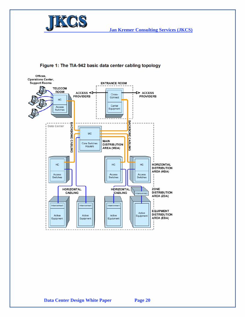
The TIA-942 standard provides several requirements and recommendations for
cabling management. The data center must be designed with separate racks and
pathways for each media type, and power and communications cables must be placed
in separate ducts.
Jan Kremer Consulting Services (JKCS)
Data Center Design White Paper Page 20
Jan Kremer Consulting Services (JKCS)
Data Center Design White Paper Page 21
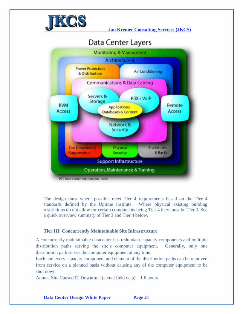
The design must where possible meet Tier 4 requirements based on the Tier 4
standards defined by the Uptime institute. Where physical existing building
restrictions do not allow for certain components being Tier 4 they must be Tier 3. See
a quick overview summary of Tier 3 and Tier 4 below.
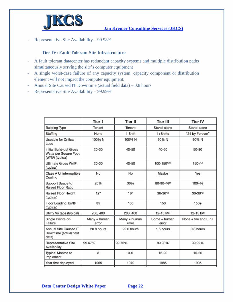
Tier III: Concurrently Maintainable Site Infrastructure
- A concurrently maintainable datacenter has redundant capacity components and multiple
distribution paths serving the site’s computer equipment. Generally, only one
distribution path serves the computer equipment at any time.
- Each and every capacity component and element of the distribution paths can be removed
from service on a planned basis without causing any of the computer equipment to be
shut down
- Annual Site Caused IT Downtime (actual field data) – 1.6 hours
Jan Kremer Consulting Services (JKCS)
Data Center Design White Paper Page 22
- Representative Site Availability – 99.98%
Tier IV: Fault Tolerant Site Infrastructure
- A fault tolerant datacenter has redundant capacity systems and multiple distribution paths
simultaneously serving the site’s computer equipment
- A single worst-case failure of any capacity system, capacity component or distribution
element will not impact the computer equipment.
- Annual Site Caused IT Downtime (actual field data) – 0.8 hours
- Representative Site Availability – 99.99%
Jan Kremer Consulting Services (JKCS)
Data Center Design White Paper Page 23
Jan Kremer Consulting Services (JKCS)
Data Center Design White Paper Page 24
3.2. CCTV and Access Control
3.2.1 Introduction
All elements of the Data Center physical security deliverables must be installed and
tested including:
CCTV System within Data Center (Computer Room) with central control
room monitors and video recording units.
Datacenter Access Control System with role based access control for the
different zones and rooms within the Datacenter including biometrics
fingerprint scanners (employees only).
Visitor “temporary” card issuance system for Data Center access for
visitors. (Optional)
Employee Access Card issuance system with Digital Camera (capturing
digital photo for card surface) and Biometrics Fingerprint Scanner
(Fingerprint minutiae on card contactless chip for 1-1 verification at
access points).
Outside CCTV (around the inside building entrance door(s) to the
Computer Room) and cameras for Datacenter perimeter (outside
Generator Set/UPS building for security management.
The security systems will utilize the existing IP network for functionality for both
access control requests and CCTV. This reduces the cost and complexity of adding
separate physical lines. Additionally, it will allow for remote monitoring and
management.
3.2.2 Physical Access Restrictions details
The most fundamental way of physically protecting the items housed in a Datacenter
is control over who can enter and who can enter in which location(s) of the Data
Center. Door Locks, Access Control Systems, fencing and lockable server cabinets
each prohibit someone from entering, that is unauthorized personnel seeing obtaining
sensitive information.
The most fundamental way of physically protecting the items housed in a Datacenter
is control over who can enter and ensure that the “who” is really the authorized
person to enter the Datacenter and its sub locations. Smartcard access control systems
with biometrics will not only ensure that controlled access is ensured but also at all
times a central control monitions system will always know “who is where at all
times”.
Jan Kremer Consulting Services (JKCS)
Data Center Design White Paper Page 25
3.2.3 Door Control Systems
A Datacenter related to manager services has several levels of access control security
such as:
Level 1: Main Access to Datacenter Facility
o This includes all personnel allowed access to the Datacenter which
includes Operators, Engineers, Management and Administration
Level 2: Access to the different Computer Rooms (Computer Room areas
such as Communications Room and Power Distribution Room), each
Computer Room area which serves different functionality should have
their own access control
Level 3: Access to Rack/Cabinets and rooms that contain secure hardware
and software such as:
o Systems containing Certification Authority hardware and software
o Smartcard Key Management Authority (KMA) hardware and
software
o Key Generation and Key Distribution hardware and software
including HSM’s
Access control should be established using contactless smartcards which store on the
chip (suggest 16-32Kb) the information of the cardholder for access control to the
different Datacenter security levels:
Name, Phone, Position, and Company organization group
Security Access level
Biometrics including digital photo and two fingerprint minutiae
Access control doors must have a “contactless” smartcard reader with fingerprint
scanner. Each card reader for each location will perform the required check. When
the person holding the card requires to access the Datacenter, and any higher level
security rooms he holds his card close to the reader, the system logs:
Date and Time accessing (and leaving)
Name etc
Then validates the Fingerprint scanned from the reader against the minutiae in the
card, when OK validates the security level allowed and opens the door or rejects
access.
All secure area’s including leaving the data center will force also the employee (or
visitor when given temporary pass) to use the card on a reader in the exit area in
order to open the door for leaving. This system now can also be utilized for:
Security audits
Time Management for employees for maintaining a log when employees were
present (automated time sheets)
Jan Kremer Consulting Services (JKCS)
Data Center Design White Paper Page 26
3.2.4 Server Area Protection
3.2.4.1 Cages
Although most Datacenters have hard-walled rooms, sometimes it has been chosen to
surround a specific server area with wire mesh fencing. This called a “cage”, such
fencing is most commonly used to sub divide a large computer room area (with
raised floors) to add additional physical security to certain select servers and
networking devices. You could go as far as creating these cages in a direct one to one
relationship as to your server zoning such as zones for:
Web Servers protected by a DMZ including firewall(s) and Intrusion Detection
Systems (IDS)
Separate zones for Application and Database Servers
Separate zones for security sensitive servers such as for:
o Certification Authority
o Key Management Authority
o Key Generation Systems for Security Cards and other PKI functions
Network and Systems Management servers such as HP OpenView and
CiscoWorks etc.
Cages can then have their own access control with the related security level related to
the server group and functions
3.2.4.2 Locking Cabinets
Another additional physical security level is to ensure that all server, network
devices, HSM devices, network management systems racks (Cabinets) are lockable
and that these cabinets are locked with proper management control over the keys for
these cabinets. This means the access control to these keys must be clearly defined
and their usage tested in practice especially for exceptional emergency conditions
3.2.5 Closed-Circuit Television Coverage
Card Reader logs can track who enters and leaves the Datacenter, bur for real time
surveillance of who enters your server environment, installation of closed-circuit
television is strongly recommended. Cameras should be placed at strategic locations
outside and inside the Datacenter and should be monitored by security personnel as
well as recorded on an Audio/Video recording system. All these physical access
control systems should be integrated with each other and complement each other.
Jan Kremer Consulting Services (JKCS)
Data Center Design White Paper Page 27
3.2.6 Access Policies and Procedures
Each Datacenter needs a proper access policy that defines who is allowed to enter
each of security levels defined, and also under what circumstances. This is usually
done by “Job Classification”. This classification must be done for all persons who
possible may have to be in these secure areas. A visitor systems access policy must
also be defined which could be for example that no visitor (even having a temporary
entry batch) can never be entering, leaving or walking around the premised without
the presence of an authorized employee.
3.2.7 ISO 27001
We recommend the implementation of an overall security policy based on ISO 27001
Information Security is a business requirement in all organizations in today’s world.
These requirements are driven either by business need or by regulations. Many
organizations find it difficult to derive a framework for defining the requirements.
ISO 27001, the Information Security Management System works as a framework
from where the organization can start the information security management
initiative.
There are several reasons why an organization should implement ISO 27001 standard
and the primary one is the business demand. The ISO 27001 certification confirms
that certain levels of protection are in place so as to protect the information / data
handled.
ISO 27001 presents the requirements to implement and operate an Information
Security Management System (ISMS). Below is an interpretation of the major
requirements and deliverables of each phase of the ISMS implementation method
established by using ISO 27001.
Our methodology for assessing and managing information risks, as well as for the
development of information security policy and procedures will be based on
ISO27001:2005 international standard and best practices.
Jan Kremer Consulting Services (JKCS)
Data Center Design White Paper Page 28
Phases involved in implementing ISO 27001
There are different ways of implementing ISO 27001 and exact phases that apply to
one organization may not be able applicable for another one. The following phases
are from a high-level overview perspective and will be covered throughout the
project phases. A unique method of implementation might be produced for each
organization depending on the organizations structure and goals.
1. Define the scope and boundaries the ISMS.
2. Identify the organization Information Security policies and procedures.
3. Define the risk assessment methodology and criteria for accepting risks.
4. Identify Information assets and assess the business impact upon the loss of
confidentiality, integrity or availability of the assets.
5. Identify and evaluate the risks:
Identify threat and vulnerabilities related to the assets.
Evaluate the impact and likelihood for these threats and
vulnerabilities, and the controls currently in place.
Estimate the level of risks based on the risk assessment
methodology.
Determine whether risks are acceptable or need treatment based on
the risk acceptance criteria.
6. Identify the options for treating the risks, whether accept, avoid, transfer
or reduce the risks by Appling additional controls.
7. Select the ISO 27001 controls which are applicable for mitigating the risks
identified.
8. Define how to measure the effectiveness of the selected controls or group
of controls and how to calculate the residual risks.
9. Document the statement of applicability.
10. Prepare risk treatment plan.
11. Implement the risk treatment plan and document it. Perform Security
Awareness training for the ISMS users.
12. Conduct Internal Audit for the implemented ISMS to measure the
effectiveness of the ISMS and perform “if needed” any corrective and
preventive actions.
Jan Kremer Consulting Services (JKCS)
Data Center Design White Paper Page 29
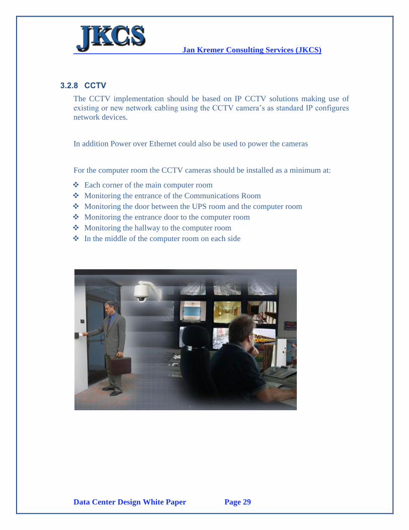
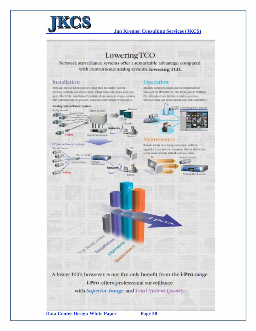
3.2.8 CCTV
The CCTV implementation should be based on IP CCTV solutions making use of
existing or new network cabling using the CCTV camera’s as standard IP configures
network devices.
In addition Power over Ethernet could also be used to power the cameras
For the computer room the CCTV cameras should be installed as a minimum at:
Each corner of the main computer room
Monitoring the entrance of the Communications Room
Monitoring the door between the UPS room and the computer room
Monitoring the entrance door to the computer room
Monitoring the hallway to the computer room
In the middle of the computer room on each side
Jan Kremer Consulting Services (JKCS)
Data Center Design White Paper Page 30
Jan Kremer Consulting Services (JKCS)
Data Center Design White Paper Page 31
3.2.9 Access Control
System Overview
Fingerprint based access control readers for entering and leaving the Computer
Room as a minimum
Manual access desk in corridor as to moving to the Computer Room entrance
door with sign-in sign-out register
Manual check in and out using register should be performed
Visitor process:
o Visitors should NEVER be given access to the computer room without
authorized employee guidance throughout the visitor presence in the
computer room
o Sign out must be performed when visitor leaves
Maintenance Engineer process:
o Engineer must sign in at entrance desk
o Engineer will be given temporary maintenance and support access card
o Engineer uses card to enter computer room
His presence in room is now logged in “room presence system”
Security at all times knows who is in the computer room in
case of fire emergency etc.
o Uses same card to exit the computer room which clears the record him
being in the room in cases of emergencies
o Special engineering card maybe required for accessing the
communications room with higher access control authority
3.2.9.1 Access Control Levels
Only limited personnel that have a need for presence in the Computer Room or High
Level Management should have access card with the proper authority to access the
computer room. The Computer Room must be identified as a high access control
zone indication so normal personnel can never use their existing ID card to enter the
Computer Room.
Jan Kremer Consulting Services (JKCS)
Data Center Design White Paper Page 32
3.3. Cabling
3.3.1 Introduction
Basic principles of a network cabling infrastructure include:
Creating a network cabling infrastructure
Points of Distribution
Avoiding Spaghetti
Labeling and Color Coding
Verification
3.3.1.1 Creating the Infrastructure
The connectivity requirements are based on device connection requirements which
are obviously defined. The most important element of the cabling infrastructure is
VERY SIMPLE, labeling and documenting that data in detail based on the TIA 606-
A Standard. Cabling must be based on the TIA-942 and TIA -568A and 568B
standards as well as the TIA-606-A Labeling and Documenting Standards.
3.3.1.2 Points of Distribution
A Point of Distribution (POD) is a rack of devices that manage a number of RLU’s.
See next page(s) to explain how this relates to the TIA-942 standards.
3.3.1.3 Avoiding Spaghetti
Cabling installations must always consider:
Calculate proper cabling lengths
Perform standard labeling and document this in the TIA 606_A database
Router Cables using the design documented
Avoid messy cabling routing
3.3.1.4 Labelling and Colour Coding
Every component of the Data Center infrastructure is to be labeled in an independent
manner consistent with the overall scheme. For purposes of tracking the fiber, the
most important things to keep in mind with the labeling system are buildings,
telecommunication rooms, fiber panels, port numbers, pedestal labels, and of course
the fiber itself.

Jan Kremer Consulting Services (JKCS)
Data Center Design White Paper Page 33
These individual identifiers can be combined to create an overall and accurate picture
of a cabling plant. Test reports will use a combination of these pieces to completely
identify any piece of the cabling plant, where it is connected and the pathway that it
follows. This requires that every piece of equipment should be labeled.
Fiber cable should be labeled on the outside jacket of the cable. Fiber panels should
be labeled on the outside of the box. Individual modules or ports inside a fiber panel
should be clearly labeled. Documentation should be located inside the fiber panel
that clearly identifies what fiber strands are connected to which bulkhead. Under no
circumstances should a technician need to open the installer's side of an LIU in order
to determine the identifier for a bulkhead or what fiber is attached to that bulkhead.
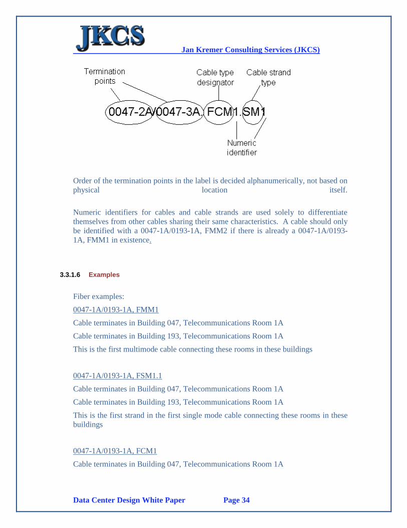
3.3.1.5 Reading a Name
A name is constructed combining the pertinent labels from the appropriate
infrastructure elements. These names will be used in documentation to track each
component of the infrastructure. Below is an example of a single mode fiber label.
For composite fiber cables, the identifier would be shown as below.
Jan Kremer Consulting Services (JKCS)
Data Center Design White Paper Page 34
Order of the termination points in the label is decided alphanumerically, not based on
physical location itself.
Numeric identifiers for cables and cable strands are used solely to differentiate
themselves from other cables sharing their same characteristics. A cable should only
be identified with a 0047-1A/0193-1A, FMM2 if there is already a 0047-1A/0193-
1A, FMM1 in existence.
3.3.1.6 Examples
Fiber examples:
0047-1A/0193-1A, FMM1
Cable terminates in Building 047, Telecommunications Room 1A
Cable terminates in Building 193, Telecommunications Room 1A
This is the first multimode cable connecting these rooms in these buildings
0047-1A/0193-1A, FSM1.1
Cable terminates in Building 047, Telecommunications Room 1A
Cable terminates in Building 193, Telecommunications Room 1A
This is the first strand in the first single mode cable connecting these rooms in these
buildings
0047-1A/0193-1A, FCM1
Cable terminates in Building 047, Telecommunications Room 1A
Jan Kremer Consulting Services (JKCS)
Data Center Design White Paper Page 35
Cable terminates in Building 193, Telecommunications Room 1A
This is the first fiber composite cable connecting these rooms in these buildings
0047-1A/0193-1A, FCM1.SM1
Cable terminates in Building 047, Telecommunications Room 1A
Cable terminates in Building 193, Telecommunications Room 1A
This is the first strand of single mode fiber in the first composite cable connecting
these rooms in these buildings
Hardware examples:
0047-1A-1FPL1
Fiber panel is located in Building 047, Telecommunications Room 1A
Fiber panel is mounted in rack number 1.
This is the first fiber panel, in the first rack, in Telco Room 1A
0047-1A-WFPL1.1/1
Fiber panel is located in Building 047, Telecommunications Room 1A
Fiber panel is mounted on the wall.
This is the first bulkhead position in the first module of this fiber panel
PCB001-WFPL1.2/4
Fiber panel is located in Pathway Cabinet #1
Fiber panel is mounted on the wall.
This is the fourth bulkhead position in the second module in this fiber panel.
3.3.1.7 The Standard in Implementation
Implementing a new labeling scheme is going to be a long multi-step process. The
first and most important step of which is to make sure that any new installations are
labeled in accordance with the new scheme.
New installations should follow the scheme as laid out above.
Jan Kremer Consulting Services (JKCS)
Data Center Design White Paper Page 36
3.3.2 How to Label:
3.3.2.1 Fiber Optic cable
1) The fiber optic cable should be labeled on the outside jacket of the cable within
8 inches of the breakout point for the individual strands. This label will follow the
conventions outlined above with a typical label being 0147-1A/0147-3A, FSM1.
2) When deciding which end of the fiber to denote first in the label, use the lower
alpha numeric characters first. For example, 0147-1A/0347-1A, FSM1 would be
proper and 0347-1A/0147-1A, FSM1 would not.
3) Individual fiber strands should be inserted into any fiber panel following the
standard color code for fiber with Blue being first and so on. This color code should
be followed so it can be read from left to right and from up to down for each
module as viewed from the front of the fiber panel. In the documentation, strand
numbers will begin at 1 and ascend in keeping with the color code. i.e. blue=1,
orange=2, green=3, and so on.
Blue-Orange-Green-Brown-Slate-White-Red-Black-Yellow-Violet-Rose-Aqua
3.3.2.2 A Fiber Panel
Outside
1) A fiber panel should be assigned an independent identifier and be labeled with it in
the upper right hand corner of the front of the LIU. Appropriate identifiers include
FPL1, FPL2, and so on.
2) A fiber panel should have a list of all fiber cables that are held in the box itself.
Often times, this will just be one fiber cable but could be much more. This list
should be preceded with an introduction of 'This FPL holds:' or the like to prevent
confusion between the fiber name and the recorded name of the fiber panel. This list
should be in the upper left hand corner of the fiber panel.
3) In the event that both ends of a particular fiber cable terminate in the same room, the
name of that cable on the front of the fiber panel should be followed by an additional
label that specifies the rack and fiber panel numbers on both ends of that cable. For
example, 0019-2A/0019-2A, FMM1 followed by WFPL6/1FPL1 would
communicate that one end of the cable terminates in a wall mounted fiber panel
labeled fpl6 and a rack mounted fiber panel labeled fpl1 in rack 1. This additional

Jan Kremer Consulting Services (JKCS)
Data Center Design White Paper Page 37
label does not add to the cable name for record purposes but exists solely to assist
technicians in the field
Inside
1) Fibers should be installed in each module of a fiber panel from left to right and
up to down in accordance as you look at the face of the bulkheads with the standard
color code for fiber installation.
2) Each fiber termination should be labeled on the boot by a number that
corresponds to its placement in the color-code of the cable
Numbers should begin at 1 and ascend from there with duplicate numbers used for
different types of fiber strands in one cable. For example, a composite fiber cable will
have multiple strands designated with a 1 to correspond to the first MM fiber cable
and the first SM fiber cable. Numbers will not refresh for different binder groups,
only for different classifications of fiber.
3) Each bulkhead will have an independent identifier. In a fiber panel that has been
subdivided in to modules, label the modules with numbers beginning with 1 and
ascending. The individual bulkheads need not be labeled and they will be identified
with numbers that begin with 1 and will be read from left to right or up to down in
accordance with the orientation of the module. In fiber panels that have not been
subdivided, the individual bulkheads will need to be identified with a number. If the
fiber panel does not come preprinted, the installer will be responsible for labeling the
bulkheads.

Jan Kremer Consulting Services (JKCS)
Data Center Design White Paper Page 38
4) A documentation page will be supplied inside the panel and should be marked
with which fiber strand matches up to which bulkhead. The installer may create a
simple spreadsheet similar to that pictured below. In this case, labeling should make
clear the identity of each bulkhead and the fiber strand that is connected to it. At this
time, copies of this spreadsheet should be sent to Network Services.
<Fiber Panel # 0047-1A-WFPL1
Module / Port Fiber Identifier
1/1 0047-1A/0149-3A, FMM1.1
1/2 0047-1A/0149-3A, FMM1.2
1/3 0047-1A/0149-3A, FMM1.3
1/4 0047-1A/0149-3A, FMM1.4
1/5 0047-1A/0149-3A, FMM1.5
1/6 0047-1A/0149-3A, FMM1.6
2/1 0047-1A/0149-3A, FMM1.7
2/2 0047-1A/0149-3A, FMM1.8
2/3 0047-1A/0149-3A, FMM1.9
2/4 0047-1A/0149-3A, FMM1.10
2/5 0047-1A/0149-3A, FMM1.11
2/6 0047-1A/0149-3A, FMM1.12
This is the first fiber panel mounted on the wall in Telco Room 1A in Building
#0047. Bulkhead #1 holds the first strand of the first fiber cable between Telco
Room 1A of Building #0047 and Telco Room 3A of Building #0149.
5) At no time should the labeling inside a fiber panel require a technician or
engineer to open the installer's side of the fiber panel to retrieve labeling information.
Bulkhead or module position labels should be apparent from a grid work sheet or
labeled explicitly by the installer.
3.3.2.3 A Communications Cabinet
Communications Cabinets are to be labeled with their standard label being
in the form of PCB###. For example, cabinet #4 would be PCB004.
Cabinets should be labeled outside on the most visible side.
Cabinets should be labeled inside as well. The inside label will be applied
to the interior of the fiber side door with the locking assembly.
Jan Kremer Consulting Services (JKCS)
Data Center Design White Paper Page 39
3.3.2.4 A Telecommunications Room
Telecommunications rooms should be labeled with the floor they are on and a letter
designation to prevent their confusion with other Telco rooms on the same floor. 1A
would designate the first floor telecommunications closet and have a designation of
A.
Unless previously labeled, Telco Rooms should be labeled on the interior of the
doorjamb near the property decal. Final labeling should consist of a plastic sign on
the outside door of the Telecommunications Room. This sign should designate the
use of the room as a Telecommunications Room and display the appropriate
identifier for that specific room; Telecommunications Room 1A, for example.
3.3.2.5 A Telecommunications Rack
Telecommunications rooms should be labeled numerically beginning with 1 and
ascending as more racks are added to the room. The rack should be clearly labeled
along the top crossbar of the rack. For purposes of this labeling standard, a
telecommunications rack is considered to be any structure capable of holding
telecommunications terminations and electronic hardware. This includes but is not
limited to 7ft free standing racks, free standing enclosures, 3-4ft wall mounted fixed
racks, and wall mounted enclosures and so on.
3.3.2.6 Conduit
An installed conduit should be labeled with the point of origin, point of termination
and a unique identifier to differentiate it from other conduit sharing the same
pathway. This label follows the same guidelines as discussed above. 0147-1A/0347-
1A, PCO1 would designate the first conduit running between building 147
telecommunications room 1A and building 347 telecommunications room 1A.
Labels should be affixed to both ends of the conduit. Labels are to be applied within
6 inches of the termination of each end of the conduit.
3.3.3 Verification
During implementation each and every patch panel port MUST be verified and
certified by the installer as part of that contract. Obviously cable testing equipment
and additional tools must be utilized to ensure proper cabling installations.
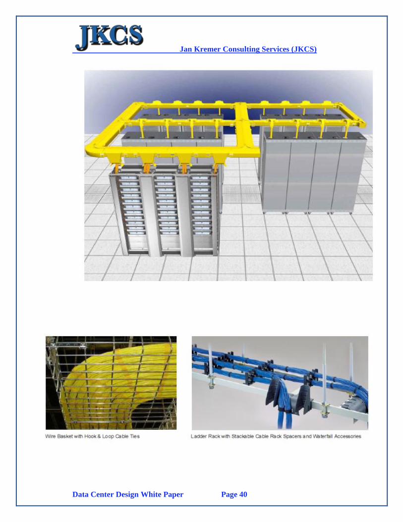
3.3.4 Network Cabling Infrastructure
The recommended network cabling structure will be based on “overhead” cable trays
which reduce cabling spaghetti under the raised floor. This also prevents
unnecessary obstructions to the cold air flow under the raised floors and prevents
complications with the Water Detection Cable. We also recommend that the Power
Cabling will also be in separate “overhead” trays considering the placement of
chilled water piping under the raised floor.
Jan Kremer Consulting Services (JKCS)
Data Center Design White Paper Page 40
Jan Kremer Consulting Services (JKCS)
Data Center Design White Paper Page 41
When deploying large volumes of servers inside the data center it is extremely
important that the design footprint is scalable.
However, access models vary between each network, and can often be extremely
complex to design. The integrated network topologies discussed in this guide take a
modular, platform-based approach in order to scale up or down as required within a
cabinet or room.
It is assumed that all compute resources incorporate resilient network, power, and
storage resources. This assumption translates to multiple LAN, SAN, and power
connections within the physical layer infrastructure. One way to simplify the design
and simultaneously incorporate a scalable layout is to divide the raised floor space
into modular, easily duplicated sub-areas.
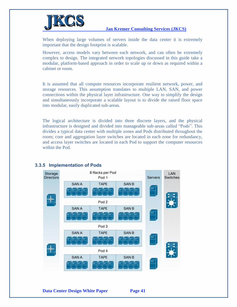
The logical architecture is divided into three discrete layers, and the physical
infrastructure is designed and divided into manageable sub-areas called “Pods”. This
divides a typical data center with multiple zones and Pods distributed throughout the
room; core and aggregation layer switches are located in each zone for redundancy,
and access layer switches are located in each Pod to support the computer resources
within the Pod.
3.3.5 Implementation of Pods
Jan Kremer Consulting Services (JKCS)
Data Center Design White Paper Page 42
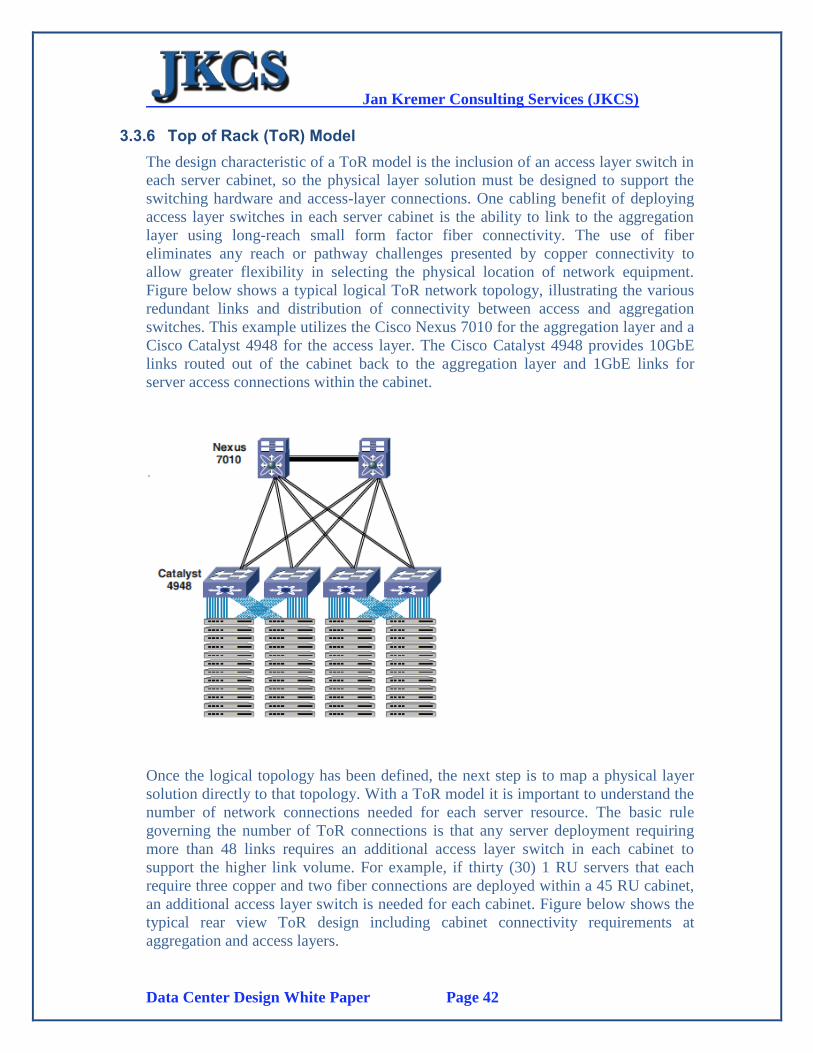
3.3.6 Top of Rack (ToR) Model
The design characteristic of a ToR model is the inclusion of an access layer switch in
each server cabinet, so the physical layer solution must be designed to support the
switching hardware and access-layer connections. One cabling benefit of deploying
access layer switches in each server cabinet is the ability to link to the aggregation
layer using long-reach small form factor fiber connectivity. The use of fiber
eliminates any reach or pathway challenges presented by copper connectivity to
allow greater flexibility in selecting the physical location of network equipment.
Figure below shows a typical logical ToR network topology, illustrating the various
redundant links and distribution of connectivity between access and aggregation
switches. This example utilizes the Cisco Nexus 7010 for the aggregation layer and a
Cisco Catalyst 4948 for the access layer. The Cisco Catalyst 4948 provides 10GbE
links routed out of the cabinet back to the aggregation layer and 1GbE links for
server access connections within the cabinet.
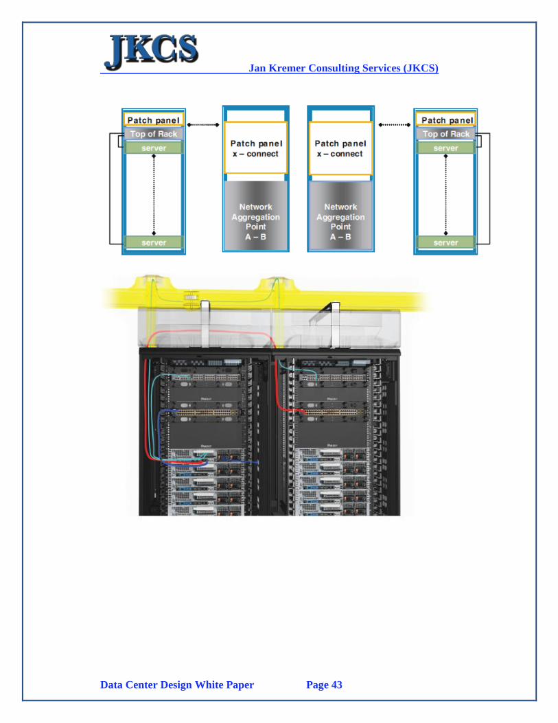
Once the logical topology has been defined, the next step is to map a physical layer
solution directly to that topology. With a ToR model it is important to understand the
number of network connections needed for each server resource. The basic rule
governing the number of ToR connections is that any server deployment requiring
more than 48 links requires an additional access layer switch in each cabinet to
support the higher link volume. For example, if thirty (30) 1 RU servers that each
require three copper and two fiber connections are deployed within a 45 RU cabinet,
an additional access layer switch is needed for each cabinet. Figure below shows the
typical rear view ToR design including cabinet connectivity requirements at
aggregation and access layers.
Jan Kremer Consulting Services (JKCS)
Data Center Design White Paper Page 43
Jan Kremer Consulting Services (JKCS)
Data Center Design White Paper Page 44
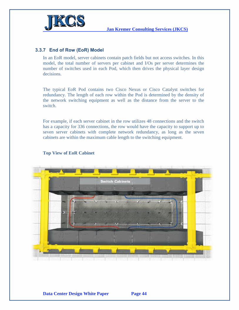
3.3.7 End of Row (EoR) Model
In an EoR model, server cabinets contain patch fields but not access switches. In this
model, the total number of servers per cabinet and I/Os per server determines the
number of switches used in each Pod, which then drives the physical layer design
decisions.
The typical EoR Pod contains two Cisco Nexus or Cisco Catalyst switches for
redundancy. The length of each row within the Pod is determined by the density of
the network switching equipment as well as the distance from the server to the
switch.
For example, if each server cabinet in the row utilizes 48 connections and the switch
has a capacity for 336 connections, the row would have the capacity to support up to
seven server cabinets with complete network redundancy, as long as the seven
cabinets are within the maximum cable length to the switching equipment.
Top View of EoR Cabinet
Jan Kremer Consulting Services (JKCS)
Data Center Design White Paper Page 45
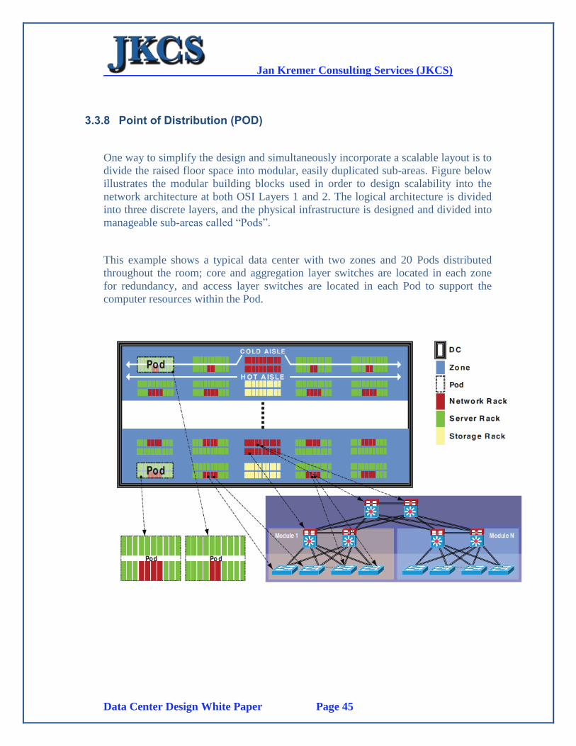
3.3.8 Point of Distribution (POD)
One way to simplify the design and simultaneously incorporate a scalable layout is to
divide the raised floor space into modular, easily duplicated sub-areas. Figure below
illustrates the modular building blocks used in order to design scalability into the
network architecture at both OSI Layers 1 and 2. The logical architecture is divided
into three discrete layers, and the physical infrastructure is designed and divided into
manageable sub-areas called “Pods”.
This example shows a typical data center with two zones and 20 Pods distributed
throughout the room; core and aggregation layer switches are located in each zone
for redundancy, and access layer switches are located in each Pod to support the
computer resources within the Pod.
Jan Kremer Consulting Services (JKCS)
Data Center Design White Paper Page 46
3.4. Fire detection and suppression
3.4.1 Introduction
Several steps must be taken to avoid fires such as:
No Smoking
No combustible materials
Always check HVAC reheat coils
Check the sprinkler/FM200 fire suppression system frequently
Preserve the data center “Cocoon”. Maintain the secure data center perimeter
Ensure you have a disaster response plan in place in case “worst case” happens
Provide easy access to fire extinguishers
The first line of fire defense and containment is the actual building structure. The
rooms and storage rooms of the data center must be isolated by fire resistant walls.
The floor and ceiling must be constructed of noncombustible or limited combustible
material. Also the HVAC system must be dedicated to the data center only.
3.4.1.1 Fire Detection Systems
The early warning fire detection system must have the following features:
Must be a heat detection type system
Installed and maintained in accordance with NFPA 72E (NFPA 2001)
Each installation should be engineered for the specific area it must protect
Some detection must be provided under the raised floor
Considering the noise in a data center, visual alerts must be provided
3.4.1.2 Fire Suppression Systems
The FM200 solution is the recommended suppression system currently available. The
FM200 uses the gas hepta-fluoropropane which is quickly dispersed around the
equipment. It works literally by removing heat energy from the fire to the extent that
the combustion reaction cannot be sustained.
It works quickly, is safe for people, does not damage the hardware or electrical
circuits and does not require a post-discharge cleanup effort. With FM200 a data
center can be back in business almost immediately after a fire.
The Datacenter will consist of a gaseous fire suppression system using FM200.
FM200 works by physically cooling the fire at a molecular level, and is safe for use
Jan Kremer Consulting Services (JKCS)
Data Center Design White Paper Page 47
around operating electronic devices and in human occupied areas. Fire detection in
the Data Center will use cross zoned photo-electric and ionization spot detectors.
Additionally, High Sensitivity Smoke Detection (HSSD) will be used for the earlier
possible detection of combustion. The Fire detection system will be integrated into
the IP network. This will allow the use of existing infrastructure instead of running
dedicated lines, and allow for remote monitoring and control. The remainder of the
Datacenter will be protected to local code standards utilizing hand held fire
extinguishers as applicable.
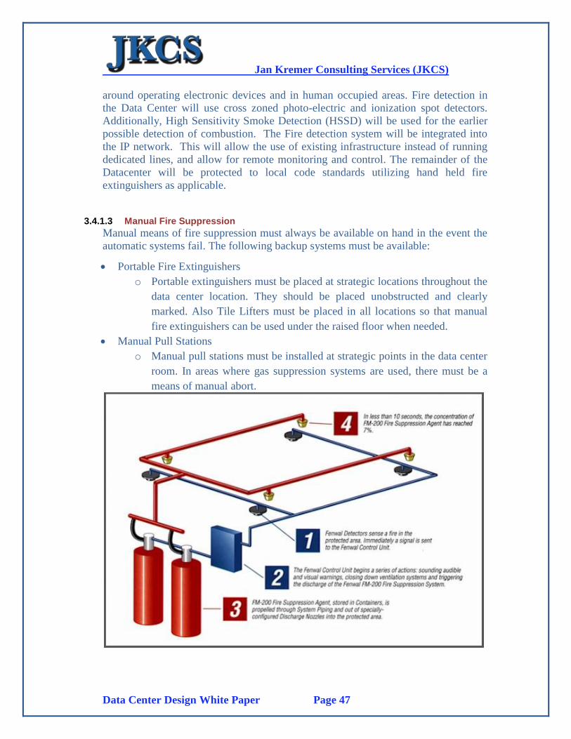
3.4.1.3 Manual Fire Suppression
Manual means of fire suppression must always be available on hand in the event the
automatic systems fail. The following backup systems must be available:
Portable Fire Extinguishers
o Portable extinguishers must be placed at strategic locations throughout the
data center location. They should be placed unobstructed and clearly
marked. Also Tile Lifters must be placed in all locations so that manual
fire extinguishers can be used under the raised floor when needed.
Manual Pull Stations
o Manual pull stations must be installed at strategic points in the data center
room. In areas where gas suppression systems are used, there must be a
means of manual abort.
Jan Kremer Consulting Services (JKCS)
Data Center Design White Paper Page 48
3.4.2 Detailed Information
The Chemetron Fire Systems Gamma Series Systems are automatic suppression
systems using the FM-200 chemical agent and consisting of four basic components
and their associated accessories.
FM-200 Components
Control Panels
Detection and Alarm Devices
Completer Kits
3.4.2.1 Features
The FM-200 components consist of agent containers, container supports (racks),
and discharge nozzles.
The control panel is the brains of the system and is used to monitor the detection
and accessories.
The detection, alarm devices, and accessories are the external devices that act as
the eyes and voice of the system as they give audible or visual signals.
The completer kits consist of warning signs, hoses, connection fittings, pressure
gauges or solenoid valves, and the actuator required to operate the cylinder valve.
The system and its components are agency tested for total flooding applications and
should be used in accordance with the guidelines contained in National Fire
Protection Association 2001. A total flooding application can be defined as injecting
FM-200 into an enclosure or volume having the structural integrity to retain the agent
during and after discharge.
The design of such a system requires that the FM-200 chemical agent be discharged
from its container within 10 seconds and be thoroughly mixed throughout the
protected volume, reaching a minimum concentration level of 6.25%, but not
exceeding 9% in normally occupied spaces.
FM 200 is a halocarbon agent accepted as an alternative to Halon for total flooding
fire suppression systems. After receiving the fire signal, FM 200 is discharged totally
from the cylinders within 10 seconds to fill up the space uniformly at the design
concentration to extinguish the fire. The agent is retained at its design concentration
in the space for a period-called 'Hold Time'-to extinguish the fire.

Jan Kremer Consulting Services (JKCS)
Data Center Design White Paper Page 49
After Hold time, when the fire is extinguished, the agent is exhausted from the space
by exhaust fans before any inspection is performed. For the design of the system,
NFPA Code 2001, "Standard on Clean Agent Fire Extinguishing Systems" is
followed.
FM 200 design includes determination of the agent quantity, piping layout, pressure
drop through the piping and accessories, as well as fixing the location and quantities
of discharge nozzles for uniform distribution of the agent throughout the space. This
also includes determining the filling density in the agent cylinders to take care of the
pressure drop through the system, for determining the number of cylinders.
From above, the agent quantity required for total flooding of the space is determined
independently based on the design concentration of the agent necessary for the type
of fire to be extinguished, Hold Time for extinguishing the fire, additional quantity
required to take care of the leakage, etc.
Tentative pipe sizing and pipe routing with nozzle location are done by the owner or
the engineer in harmony with the other facilities in the space. This is, however,
finalized by the agent supplier's authorized system designer based on the pressure
drop software program for two-phase flow of the agent.
To take care of the system pressure drop and to establish the required pressure at the
nozzles, the authorized agent determines the agent fill density in the cylinder. They
also finalize the number of cylinders based on the fill density and their standard
cylinder size.
The areas to be protected are identified from the fire risk analysis of the plant and the
various codes (like NFPA, etc). The requirements are guided by the functional
criticality of the system protected, amount of loss involved, fire insurance premium,
etc
A typical case of protecting a power station using the FM 200 total suppression
system is the basis for the following design information. Design Code: NFPA 2001,
"Clean Agent Fire Extinguishing System," is the governing code for designing the
system, and NFPA 72, "National Fire Alarm Code," is followed for fixing the fire
alarm system, an important part of the clean agent total suppression system.
Jan Kremer Consulting Services (JKCS)
Data Center Design White Paper Page 50
Agent Concentration: Since FM 200 is the most expensive item of the total system, a
careful analysis is required before fixing the required concentration and the total
quantity of the agent.
Regarding design concentration of the agent, there are various guidelines available,
such as:
120% of cup burner value verified by listing/approval tests, minimum design
concentration (%V/V) of FM 200 is 7%, (refer to Table 4-7.5 Weight and Storage
Volume Equivalent data for New Technology Halocarbon Gaseous alternatives'
SFPE Handbook on Fire Protection Engineering).
The same agent concentration of 7% is accepted by Factory Mutual (FM) as the
design agent concentration.
Underwriters' Laboratories (UL), however, recommends the agent design
concentration as 7.44%.
To satisfy both FM and UL, it seems prudent to consider the design concentration as
7.44% by volume. The FM 200 supplier's authorized agent normally recommends 7%
as the design concentration, based on their experience with the type of fire
anticipated in the areas protected. Increase of the agent concentration from 7% to
7.44% has the repercussion on the cost of the agent. If possible, the recommendation
of the AHJ (Authority of Jurisdiction) should be solicited before fixing the agent
design concentration.
The maximum limit of the FM 200 concentration is restricted by NFPA 2001 due to
the safety considerations of the toxicological and physical effects on human life.
The recommended FM-200 installation will include 2 large Gas containers placed on
the right wall next to one of the main pillars and include app. 300 nozzles distributed
over the Computer Room floor space as well as the Communications Room
HP OpenView integration is established through the Chemetron detection and alarm
devices which are viewed and monitored under HP OpenView as SNMP devices.
Jan Kremer Consulting Services (JKCS)
Data Center Design White Paper Page 51
3.5. HVAC
3.5.1 Introduction
HVAC and other environmental controls are essential for a data center. Computer
Hardware requires a balanced and appropriate environment for continuous system
operation.
Temperatures and relative humidity levels outside of the specified operating ranges
or extreme swings in conditions can lead to unreliable components or system failures.
Control of these environmental factors also has an effect on the control of
electrostatic discharge and corrosion of system components.
This introduction section includes:
Reasons for control
Temperature Requirements
Relative Humidity
Electrostatic Discharge
3.5.1.1 Reasons for control
Computer rooms require precise and adaptable temperature control because:
Need for cooling
o Data Centers have a dense heat load
Cooling is needed where required
o Heat load varies across an area of equipment placement
Precise cooling is needed
o Data Center cooling require higher sensible heat ratio than office areas and
precision systems require 85 to 100% cooling while normal comfort
systems require much less
Controls much be adaptable
o Heat load will change with additional equipment configurations and also
outside temperature changes will affect integral cooling requirements as is
the case in Saudi Arabia.
Data Centers need frequent air exchange
o Precision cooling systems must support cooling at an adequate range.
Precision Air Conditioners pass more than 500 cubic feet per minute per
ton while comfort systems pass only an average of 350 CFM.
Jan Kremer Consulting Services (JKCS)
Data Center Design White Paper Page 52
3.5.1.2 Temperature Requirements
General temperature requirements for a data center are in the range of 70 to 74 F
which is 21 to 23 Celsius. Most Computer Equipment works best in a 22 Celsius
environment.
Critical conditions apply such as:
Component failure
AC failure
Installations and de-installations and reconfigurations
Removal of floor tiles and changes in cabling
Doors left open
3.5.1.3 Relative Humidity
Relative Humidity (RH) is the amount of moisture in a given sample of air at a given
temperature in relation to the maximum amount of moisture that the sample could
contain at the same temperature. If the air is holding all the moisture it can hold for a
specific set for conditions then it is said to be saturated (100% RH). Since air is a gas,
it expands as it is heated, and as it gets warmer the amount of moisture it can hold
increases.
Ambient Levels between 45 and 50% RH are optimal for system reliability. Most
Data Processing Equipment works between 20 to 80 % RH although 45-50% is
preferred. High Relative Humidity conditions can create damage from condensation,
while low Relative Humidity conditions can lead to an increased chance of
Electrostatic Discharge.
3.5.1.4 Electrostatic Discharge
Electrostatic Discharge (ESD) is the rapid discharge of static electricity between
bodies of different electrical potentials and can damage electronic components. ESD
can change the electrical characteristics of a semiconductor device, degrading or
destroying it.

Jan Kremer Consulting Services (JKCS)
Data Center Design White Paper Page 53
3.5.2 Details
We recommend a Tier 4 Chiller (Chilled Water Supply for all Rack cooling units as
well as the chilled water CRAC units (HP Superdomes, a TANDEM Base24 system
and HP SAN as well as overall room AC).
The design incorporates two (2) Chiller units will be configured in a
redundant/failover configuration to provide maximum availability of the HVAC
system. Both units will be installed on the roof of the UPS room.
Weight requirements etc are included in the design document for the Generator Set
and UPS construction requirements.
3.5.2.1 Chilled Liquid Systems
The basic premise of a chilled liquid system is that air goes through its intake and is
passed through a set of filters which are electrically charged. Once filtered the air
passes through a series of coils that contain fluid at much lower temperature than the
air. The cooled air is then passed out of the HVAC at a higher speed. HVAC units
also include humidifiers to change the RH of the air to keep it at the appropriate
level.
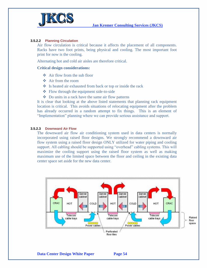
Jan Kremer Consulting Services (JKCS)
Data Center Design White Paper Page 54
3.5.2.2 Planning Circulation
Air flow circulation is critical because it affects the placement of all components.
Racks have two foot prints, being physical and cooling. The most important foot
print for now is the cooling.
Alternating hot and cold air aisles are therefore critical.
Critical design considerations:
Air flow from the sub floor
Air from the room
Is heated air exhausted from back or top or inside the rack
Flow through the equipment side-to-side
Do units in a rack have the same air flow patterns
It is clear that looking at the above listed statements that planning rack equipment
location is critical. This avoids situations of relocating equipment after the problem
has already occurred in a random attempt to fix things. This is an element of
“Implementation” planning where we can provide serious assistance and support.
3.5.2.3 Downward Air Flow
The downward air flow air conditioning system used in data centers is normally
incorporated using raised floor designs. We strongly recommend a downward air
flow system using a raised floor design ONLY utilized for water piping and cooling
support. All cabling should be supported using “overhead” cabling systems. This will
maximize the cooling support using the raised floor system as well as making
maximum use of the limited space between the floor and ceiling in the existing data
center space set aside for the new data center.
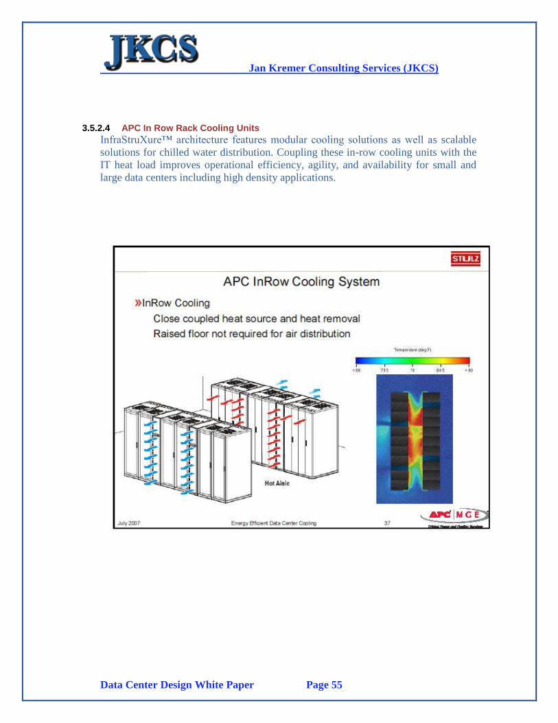
Jan Kremer Consulting Services (JKCS)
Data Center Design White Paper Page 55
3.5.2.4 APC In Row Rack Cooling Units
InfraStruXure™ architecture features modular cooling solutions as well as scalable
solutions for chilled water distribution. Coupling these in-row cooling units with the
IT heat load improves operational efficiency, agility, and availability for small and
large data centers including high density applications.
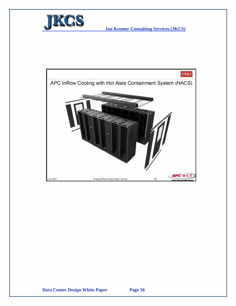
Jan Kremer Consulting Services (JKCS)
Data Center Design White Paper Page 56
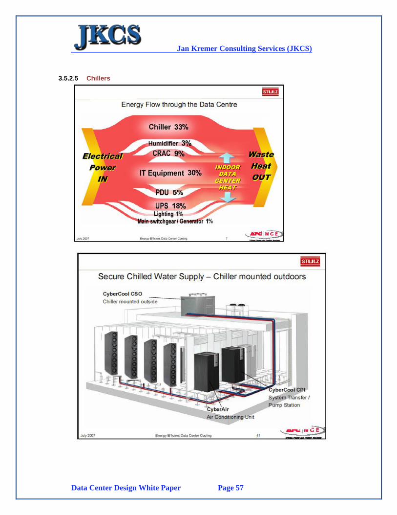
Jan Kremer Consulting Services (JKCS)
Data Center Design White Paper Page 57
3.5.2.5 Chillers
Jan Kremer Consulting Services (JKCS)
Data Center Design White Paper Page 58
3.6. Lighting
3.6.1 Introduction
Use Occupancy Sensors
o Occupancy sensors can be a good option for datacenters that are
infrequently occupied. Thorough area coverage with occupancy sensors or
an override should be used to insure the lights stay on during installation
procedures when a worker may be 'hidden' behind a rack for an extended
period.
Provide Bi-Level Lighting
o Provide two levels of clearly marked, easily actuated switching so the
lighting level can be easily changed between normal, circulation space
lighting and a higher power detail work lighting level. The higher power
lighting can be normally left off but still be available for installation and
other detail tasks.
Provide Task Lighting
o Provide dedicated task lighting specifically for installation detail work to
allow for the use of lower, circulation space and halls level lighting
through the datacenter area.
3.6.2 Occupancy Sensor Application
Occupancy sensors are "application-sensitive" devices, meaning that most problems
in the field are the result of misapplication. Here are some general guidelines that can
help with occupancy sensor application:
Calibrate the sensor. The sensor will be provided with manufacturer-default
settings for sensitivity to magnitude of motion and time delay before
switching the lights off. The default time delay may be from 30 seconds to 15
minutes. Be sure to calibrate the sensor to specific conditions in the space for
best performance.
Understand local occupancy patterns. Occupancy sensors generate the greatest
savings in spaces where occupancy is unpredictable and/or intermittent.
Line of sight must be maintained between the sensor and the occupant except
in the case of an enclosed space with hard surfaces covered by an ultrasonic
sensor. Be sure to view sensor specifications to determine the amount of
coverage that will be provided to the space by the sensor; this will aid with
choosing the number of sensors required to cover an area properly and where
to place them.

Jan Kremer Consulting Services (JKCS)
Data Center Design White Paper Page 59
The amount of motion required to keep the lights on is based on distance
between the sensor and the occupant. Ultrasonic sensors are more sensitive at
greater distances than PIR sensors.
Avoid conditions that may result in false triggering. Conditions to generally
avoid include using an ultrasonic sensor for restricted-coverage areas and
high-bay and outdoor applications; setting the ultrasonic sensor to maximum
sensitivity so that it picks up small non-human movements in the space; and
setting the sensor so that it turns off too quickly or cannot see the occupant,
such as bathrooms/stalls. Avoid placing an ultrasonic sensor where it can pick
up vibrations and air currents, and placing a PIR sensor where it is exposed to
direct sunlight that can trigger it. If a PIR sensor has a line of sight into an
adjacent hallway, resulting in false triggers, then simply put a masking label
on the section of the lens that can "see" into the hallway to restrict its
coverage.
Consider the direction of motion. Ultrasonic sensors are most sensitive to
occupants moving towards and away from the sensor, while PIR sensors are
most sensitive to lateral motion.
Check the load limits for the sensor selected. Ensure that the load handled by
the sensor is within the minimum and maximum limits specified by the
manufacturer.
Check with the manufacturer to determine if there is a limitation in
compatibility with any other lighting equipment, such as electronic ballasts.
Determine switching’s effect on lamp life. Frequent switching can shorten
lamp life, particularly if the lamps are instant start lamps. However, also
calculate into the total impact of occupancy sensors the effect of reduced
operating hours.
Trial installation. Consider a trial installation to learn more about actual
occupancy sensor performance in a given space before full installation. Note
that most occupancy sensors include an LED to indicate that the sensor is
detecting occupancy/motion.
Commission the system. After installation, set the desired time delay and
sensitivity, and then calibrate performance by testing the sensors.
We also recommend that the “lighting rows” are above the “cold aisles” so that any
heat generation is controlled by the Hot/Cold Aisle cooling implementation. Using
motion sensors with occupancy sensors will switch off lighting when not needed and
considerably reduce power usage as well as heat dissipation into the computer room.
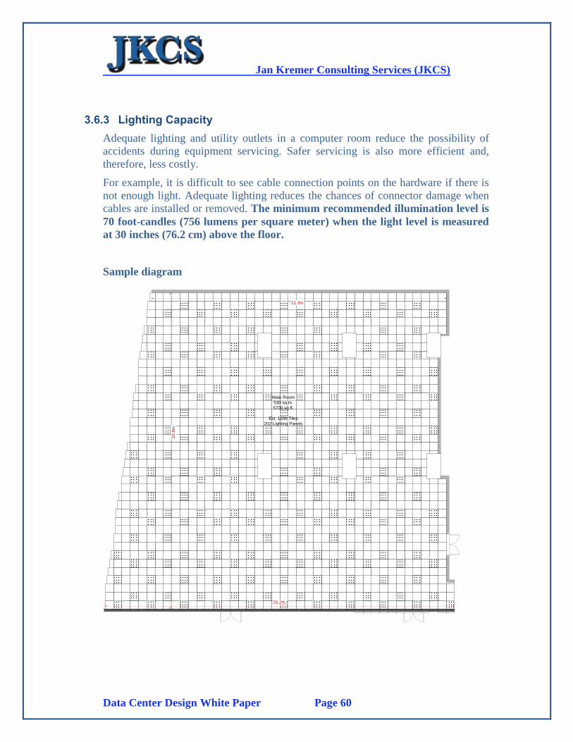
Jan Kremer Consulting Services (JKCS)
Data Center Design White Paper Page 60
3.6.3 Lighting Capacity
Adequate lighting and utility outlets in a computer room reduce the possibility of
accidents during equipment servicing. Safer servicing is also more efficient and,
therefore, less costly.
For example, it is difficult to see cable connection points on the hardware if there is
not enough light. Adequate lighting reduces the chances of connector damage when
cables are installed or removed. The minimum recommended illumination level is
70 foot-candles (756 lumens per square meter) when the light level is measured
at 30 inches (76.2 cm) above the floor.
Sample diagram
25.2m.
22
.8m
.
21.3m.
Main Room
530 sq m.
5700 sq ft.
Est. 1256 Tiles
202 Lighting Panels
Jan Kremer Consulting Services (JKCS)
Data Center Design White Paper Page 61
3.7. Monitoring and Management
3.7.1 Introduction
A comprehensive monitoring system is important for the design and maintenance of a
data center facility. It also provides an invaluable tool for diagnosing and correcting
problems, collecting historical data for systems evaluations and for day to day
verifications and corrections. The following data is critical for monitoring systems
designs:
Room conditioning feedback should not be based on one sensor in one part of
the Data Center room since it could provide confusing and incorrect data.
Multiple sensors are required with multiple data gathering capabilities
Historical trend capabilities must be provided
Critical alarms must be provided
Must be integrated with centralized data center tracking system, including
Building Management and Security
Must include HVAC and AC monitoring
Must include standard IP and SNMP protocols
Monitoring System Status, Health and load is a useful tool for understanding how
each system is working, by itself and in relationship with other connected systems. It
is important to understand that systems monitoring should conform to industry
standards such as SNMP. All systems including HVAC, UPS etc., should be
connected through the network complying with the SNMP basic standard. The most
critical monitoring components in the Data Center:
UPS and Generator Sets
CRAC (Chillers) and Rack Cooling Units
Fire Protection and Detection (FM200)
Water Leakage
3.7.2 Details
The Monitoring System recommended is a combination of an integrated Data Center
Infrastructure monitoring system provided by APC/Schneider. Main Power
Monitoring is based on the PMS system provided by Schneider (See Below)
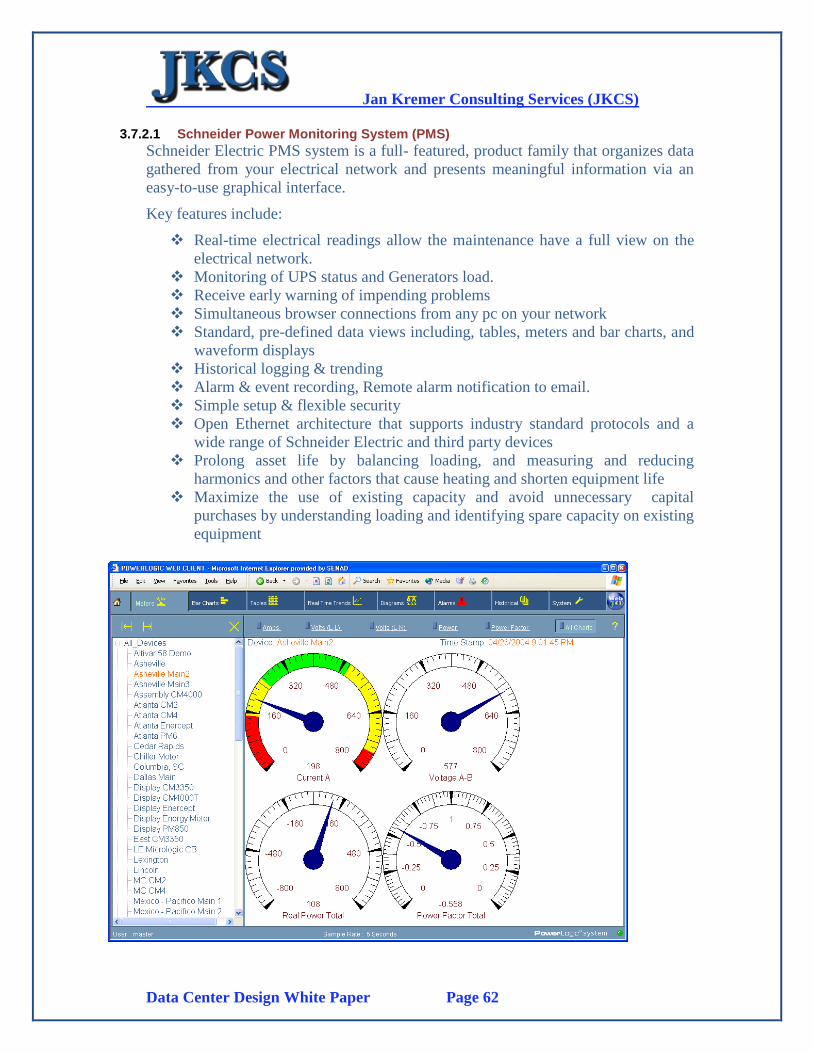
Jan Kremer Consulting Services (JKCS)
Data Center Design White Paper Page 62
3.7.2.1 Schneider Power Monitoring System (PMS)
Schneider Electric PMS system is a full- featured, product family that organizes data
gathered from your electrical network and presents meaningful information via an
easy-to-use graphical interface.
Key features include:
Real-time electrical readings allow the maintenance have a full view on the
electrical network.
Monitoring of UPS status and Generators load.
Receive early warning of impending problems
Simultaneous browser connections from any pc on your network
Standard, pre-defined data views including, tables, meters and bar charts, and
waveform displays
Historical logging & trending
Alarm & event recording, Remote alarm notification to email.
Simple setup & flexible security
Open Ethernet architecture that supports industry standard protocols and a
wide range of Schneider Electric and third party devices
Prolong asset life by balancing loading, and measuring and reducing
harmonics and other factors that cause heating and shorten equipment life
Maximize the use of existing capacity and avoid unnecessary capital
purchases by understanding loading and identifying spare capacity on existing
equipment
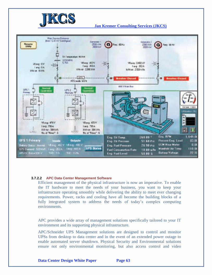
Jan Kremer Consulting Services (JKCS)
Data Center Design White Paper Page 63
3.7.2.2 APC Data Center Management Software
Efficient management of the physical infrastructure is now an imperative. To enable
the IT hardware to meet the needs of your business, you want to keep your
infrastructure operating smoothly while delivering the ability to meet ever changing
requirements. Power, racks and cooling have all become the building blocks of a
fully integrated system to address the needs of today’s complex computing
environments.
APC provides a wide array of management solutions specifically tailored to your IT
environment and its supporting physical infrastructure.
APC/Schneider UPS Management solutions are designed to control and monitor
UPSs from desktop to data center and in the event of an extended power outage to
enable automated server shutdown. Physical Security and Environmental solutions
ensure not only environmental monitoring, but also access control and video
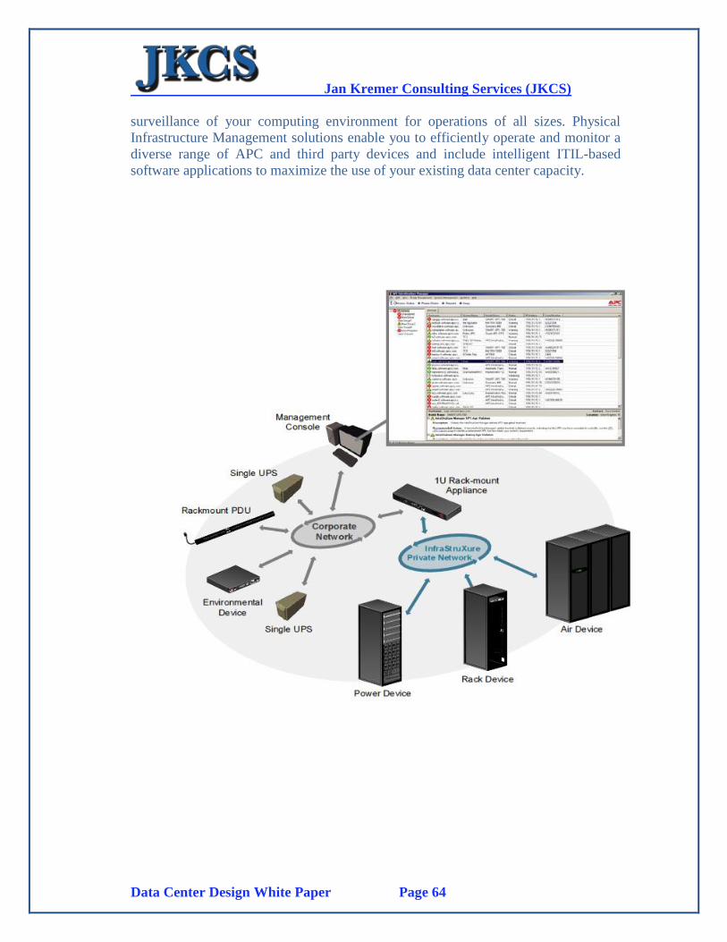
Jan Kremer Consulting Services (JKCS)
Data Center Design White Paper Page 64
surveillance of your computing environment for operations of all sizes. Physical
Infrastructure Management solutions enable you to efficiently operate and monitor a
diverse range of APC and third party devices and include intelligent ITIL-based
software applications to maximize the use of your existing data center capacity.
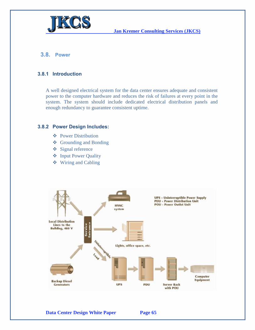
Jan Kremer Consulting Services (JKCS)
Data Center Design White Paper Page 65
3.8. Power
3.8.1 Introduction
A well designed electrical system for the data center ensures adequate and consistent
power to the computer hardware and reduces the risk of failures at every point in the
system. The system should include dedicated electrical distribution panels and
enough redundancy to guarantee consistent uptime.
3.8.2 Power Design Includes:
Power Distribution
Grounding and Bonding
Signal reference
Input Power Quality
Wiring and Cabling
Jan Kremer Consulting Services (JKCS)
Data Center Design White Paper Page 66
3.8.2.1 Power Distribution
Power distribution should support adequate and consistent power supply with
dedicated power distribution units (PDU) and sufficient redundancy to guarantee
constant uptime supporting Tier 4 class infrastructure.
Two (2) Power Backup Generator Sets (N+1) will be designed each providing the
required backup power supply needed. Accommodations will be made to allow the
installation of a third generator when the second power input is delivered.
Backup Power Generators must be able to carry the load of the data center load.
Although it is sometimes necessary, sharing breakers is not recommended.
Maintenance Bypass
The Power Design System must provide the means for bypassing and isolating any
point of the system to allow for maintenance, repair, or modifications without
disrupting operations.
3.8.2.2 Grounding and Bonding
Grounding is the creation of a path to an electronically conductive body, such as
earth which maintains a zero potential (not positively or negatively charged) for
connecting to an electrical circuit. This is done by connecting the data center
equipment at the power source to an earth grounding electrode subsystem which is a
network of interconnected rods, plates, mats, or grids installed to establish a low
resistance contact with earth.
A final reason for proper grounding is noise control which is an important aspect of
power quality. Bonding is the means by which two or more grounding rods are
connected. Proper bonding techniques are critical to proper grounding. A solid and
well bonded grounding system will allow circuit breakers and power sequencers
connected to grounded outlets and have a safe path to ground if an over current
situation occurs.
Equipment Grounding Conductor Impedance
The Data Center must have its own grounding plan which will tie into the earth
ground for the building. The System must have sufficient low resistance to allow
circuit breakers, surge protectors and power sequencers to respond to this over
current state very quickly.
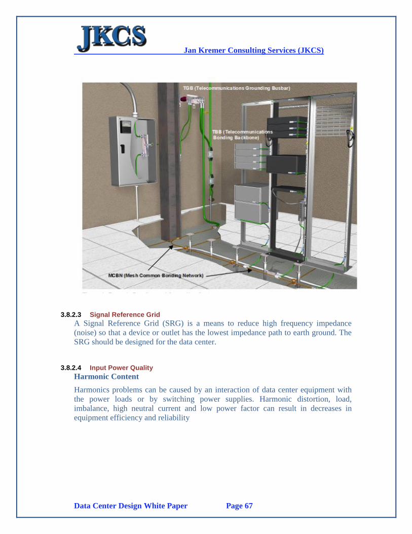
Jan Kremer Consulting Services (JKCS)
Data Center Design White Paper Page 67
3.8.2.3 Signal Reference Grid
A Signal Reference Grid (SRG) is a means to reduce high frequency impedance
(noise) so that a device or outlet has the lowest impedance path to earth ground. The
SRG should be designed for the data center.
3.8.2.4 Input Power Quality
Harmonic Content
Harmonics problems can be caused by an interaction of data center equipment with
the power loads or by switching power supplies. Harmonic distortion, load,
imbalance, high neutral current and low power factor can result in decreases in
equipment efficiency and reliability

Jan Kremer Consulting Services (JKCS)
Data Center Design White Paper Page 68
Voltage Spikes
Voltage spikes are rises in the voltage caused within the power distribution units.
This is why a proper UPS system is required.
Lightning Protection
The potential damaging effects of lightning on computer systems can be direct or
indirect.
It might be on the utility power feed, directly on the equipments, or through high-
frequency electromagnetic interference or sure currents. The design includes paths
for surge entry and surge arrestors.
3.8.2.4.1.1.1 Power Distribution Units
A Power Distribution Unit (PDU) is a way to integrate circuit breakers, wire band
outlets into a single central location on the floor that can serve multiple Rack
Location Units (RLU). This gives a lot of flexibility to the electrical system design.
Properly designed PDU’s offer a great deal of flexibility to your electrical design.
3.8.3 Details
3.8.3.1 New power infrastructure for new Data Center
This section provides an overview of the overall power design which includes:
Main Power Input
Transformers
Generator Sets
Uninterruptable Power Supply
Power Distribution Units
Transformers
We recommend transformers of 1.5MW capacity. These transformers are normally
provided by SCECO although they, as well as the Cummins Generator Sets can be
provided by APC/Schneider. Also the UPS systems can be provided by
APC/Schneider. In summary the whole Power Solution can be provided by a single
organization (Schneider) making warranty, maintenance and support much more cost
effective.
Jan Kremer Consulting Services (JKCS)
Data Center Design White Paper Page 69
3.8.3.2 Generator Set
Introduction
The Generator Set(s) will be configured as per the Tier 3-4 requirements and there
will be one active set and a standby (switchable) set. Each Generator must be able to
handle as a minimum the total SCECO provide power input which is 1500 kVA. The
generator set must provide as a minimum 1500 kVA in prime mode and not standby
mode. Standby Mode power supply is usually 15-20% more than “Prime Mode”.
Prime Mode
Prime Mode is the output available with varying load for an unlimited time. Average
power output is 70% of the prime power rating.
Typical peak demand of 100% of prime-rated ekW with 10% of overload
capability for emergency use for a maximum of 1 hour in 12
Overload operation cannot exceed 25 hours per year.
Prime power in accordance with ISO8528
Fuel stop power in accordance with ISO3046
Standby Mode
Standby Mode is the output available with varying load for the duration of the
interruption of the normal source power. Average power output is 70% of the standby
power rating. Typical operation is 200 hours per year, with maximum expected usage
of 500 hours per year. Fuel stop power in accordance with ISO3046
3.8.3.3 UPS System
The design for the UPS system is based on a Tier 3/4 configuration. One active UPS
system is switchable with a redundant second fully configured UPS system. Each
UPS configuration will initially be configured for 600 KW which is 750 KVA and
expandable to 1600 KW which is 2000 KVA.
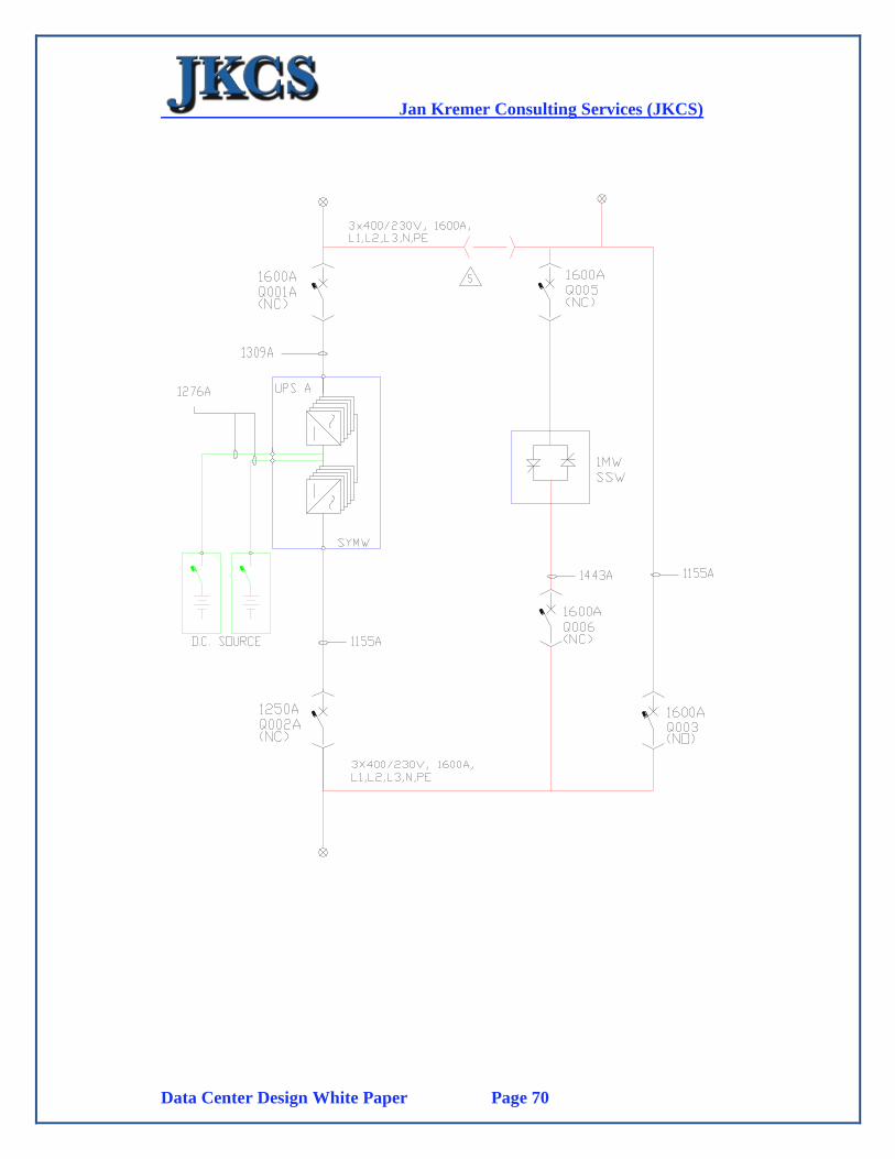
Jan Kremer Consulting Services (JKCS)
Data Center Design White Paper Page 70
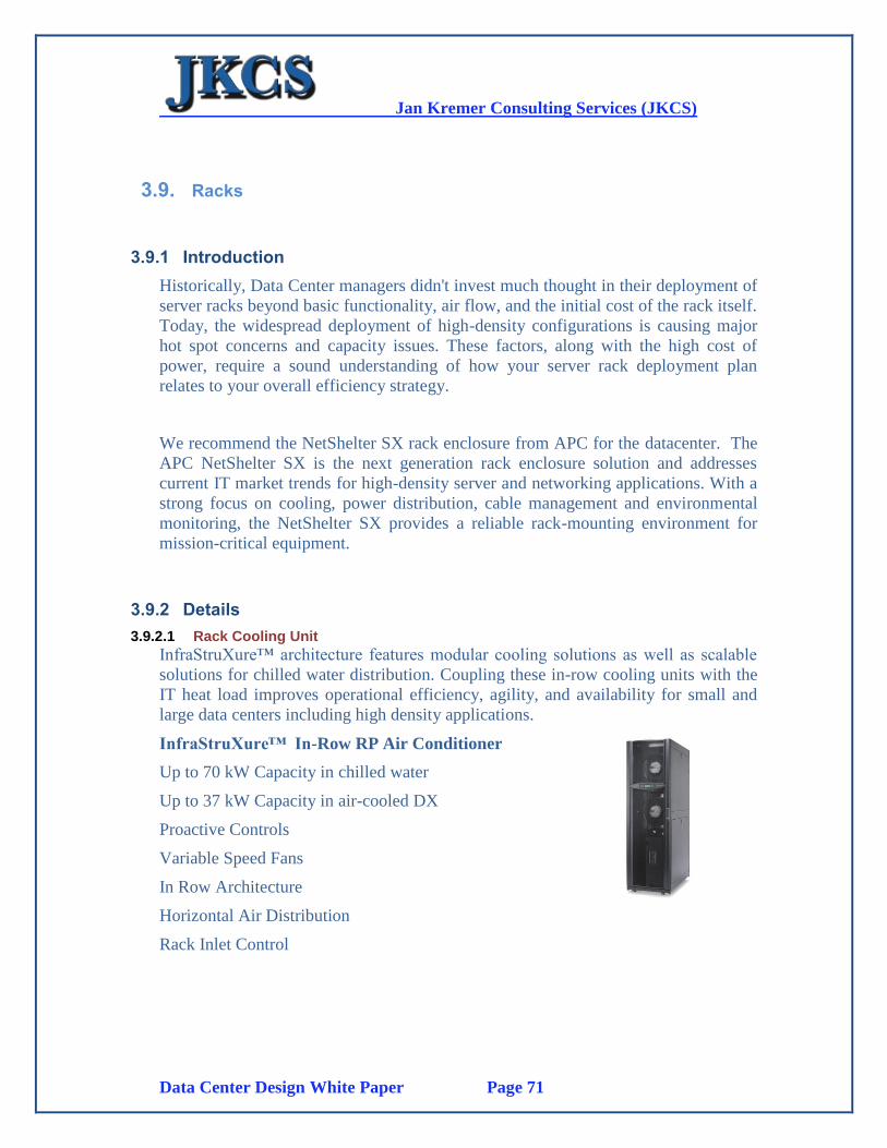
Jan Kremer Consulting Services (JKCS)
Data Center Design White Paper Page 71
3.9. Racks
3.9.1 Introduction
Historically, Data Center managers didn't invest much thought in their deployment of
server racks beyond basic functionality, air flow, and the initial cost of the rack itself.
Today, the widespread deployment of high-density configurations is causing major
hot spot concerns and capacity issues. These factors, along with the high cost of
power, require a sound understanding of how your server rack deployment plan
relates to your overall efficiency strategy.
We recommend the NetShelter SX rack enclosure from APC for the datacenter. The
APC NetShelter SX is the next generation rack enclosure solution and addresses
current IT market trends for high-density server and networking applications. With a
strong focus on cooling, power distribution, cable management and environmental
monitoring, the NetShelter SX provides a reliable rack-mounting environment for
mission-critical equipment.
3.9.2 Details
3.9.2.1 Rack Cooling Unit
InfraStruXure™ architecture features modular cooling solutions as well as scalable
solutions for chilled water distribution. Coupling these in-row cooling units with the
IT heat load improves operational efficiency, agility, and availability for small and
large data centers including high density applications.
InfraStruXure™ In-Row RP Air Conditioner
Up to 70 kW Capacity in chilled water
Up to 37 kW Capacity in air-cooled DX
Proactive Controls
Variable Speed Fans
In Row Architecture
Horizontal Air Distribution
Rack Inlet Control
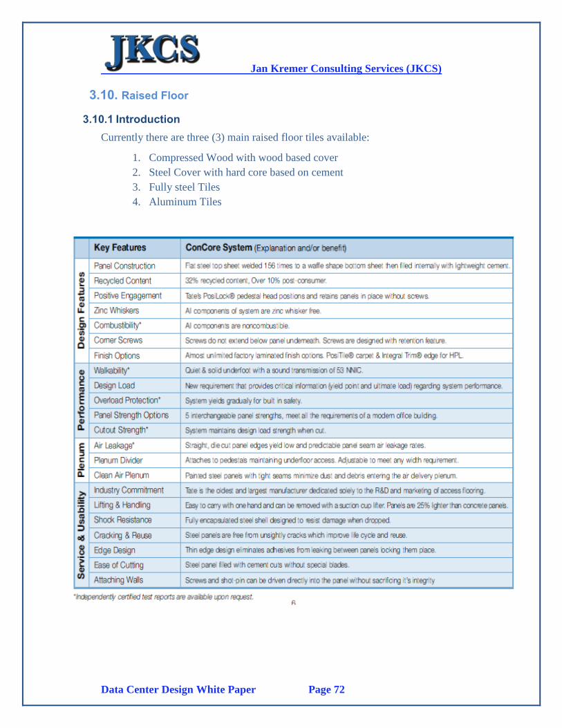
Jan Kremer Consulting Services (JKCS)
Data Center Design White Paper Page 72
3.10. Raised Floor
3.10.1 Introduction
Currently there are three (3) main raised floor tiles available:
1. Compressed Wood with wood based cover
2. Steel Cover with hard core based on cement
3. Fully steel Tiles
4. Aluminum Tiles

Jan Kremer Consulting Services (JKCS)
Data Center Design White Paper Page 73

Jan Kremer Consulting Services (JKCS)
Data Center Design White Paper Page 74
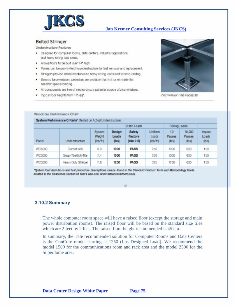
Jan Kremer Consulting Services (JKCS)
Data Center Design White Paper Page 75
3.10.2 Summary
The whole computer room space will have a raised floor (except the storage and main
power distribution rooms). The raised floor will be based on the standard size tiles
which are 2 feet by 2 feet. The raised floor height recommended is 45 cm.
In summary, the Tate recommended solution for Computer Rooms and Data Centers
is the ConCore model starting at 1250 (Lbs Designed Load). We recommend the
model 1500 for the communications room and rack area and the model 2500 for the
Superdome area.

Jan Kremer Consulting Services (JKCS)
Data Center Design White Paper Page 76
3.11. RF Shielding
3.11.1 Introduction
Shielding is a way of preventing electronic emissions that are generated from a
computer or network from being used by unauthorized users for gathering
information. It minimizes the chances of eavesdropping within a network. Shielding
can be provided by surrounding a computer room with a “Faraday” cage.
3.11.2 Details
We suggest a product called SM-10 Flexible Metallic Fabrics. SM-10 Metalized
Fabrics provide:
EMI/RF shielding up to 60 db
Exceptional resilience and comfortably attaches to a variety of surfaces
Superior RF leak prevention
SM-10 is available in copper or nickel/copper fabrics
In Computer Room applications SM-10 is applied to walls, ceilings and floors.
We have marked the walls that are outside walls of the building. They are clearly the
vulnerable areas for RF and EMI. We suggest applying SM-10 to these walls to
avoid exposure of wireless RF signals to the outside world as well as blocking any
external interference sources.
Jan Kremer Consulting Services (JKCS)
Data Center Design White Paper Page 77
3.12. Water Detection
3.12.1 Introduction
Like fire, flooding can be caused by either equipment failure or by natural causes.
While the design should attempt to prohibit water pipes from passing through the
data center, sometimes this cannot be avoided.
Moisture below the floor can damage wiring or equipment and cause costly
downtime. An under floor water detection system can give you an immediate
warning. One with a LCD display will show you the exact location of the leak
reducing the chance of costly damage. The location of the leak is displayed on the
control panel so you can use your time to resolve the leak rather than looking for it.
The design requires a proper water detection system design which is described in
more detail in the next section.
3.12.2 Details
3.12.2.1 RLE Technologies
The Water Leakage High level Design is based on a “Distance Detection” cabling
system under the raised floor. The two components required are the control unit and
the leakage detection cable which must support the 660 square meter floor space of
the Computer Room.
The distance-read system pinpoints the location of a water leak. Distance-read
systems are particularly useful in facilities with large raised-floor areas. This
technology features a water leak detection cable, up to 5000 feet in length. The cable
is placed in a serpentine pattern on the sub-floor, around all possible leak sources. If
a leak occurs, the control head annunciates this information. The control head then
provides a distance measurement. This distance measurement is cross referenced
with the water leak detection reference map, and the location of the leak is pinpointed
within a few feet.
Following is a summary of the two main components of the water leakage detection
system. The option presented here from RLE Technologies a US based technology
supplier with distribution in the Middle East.
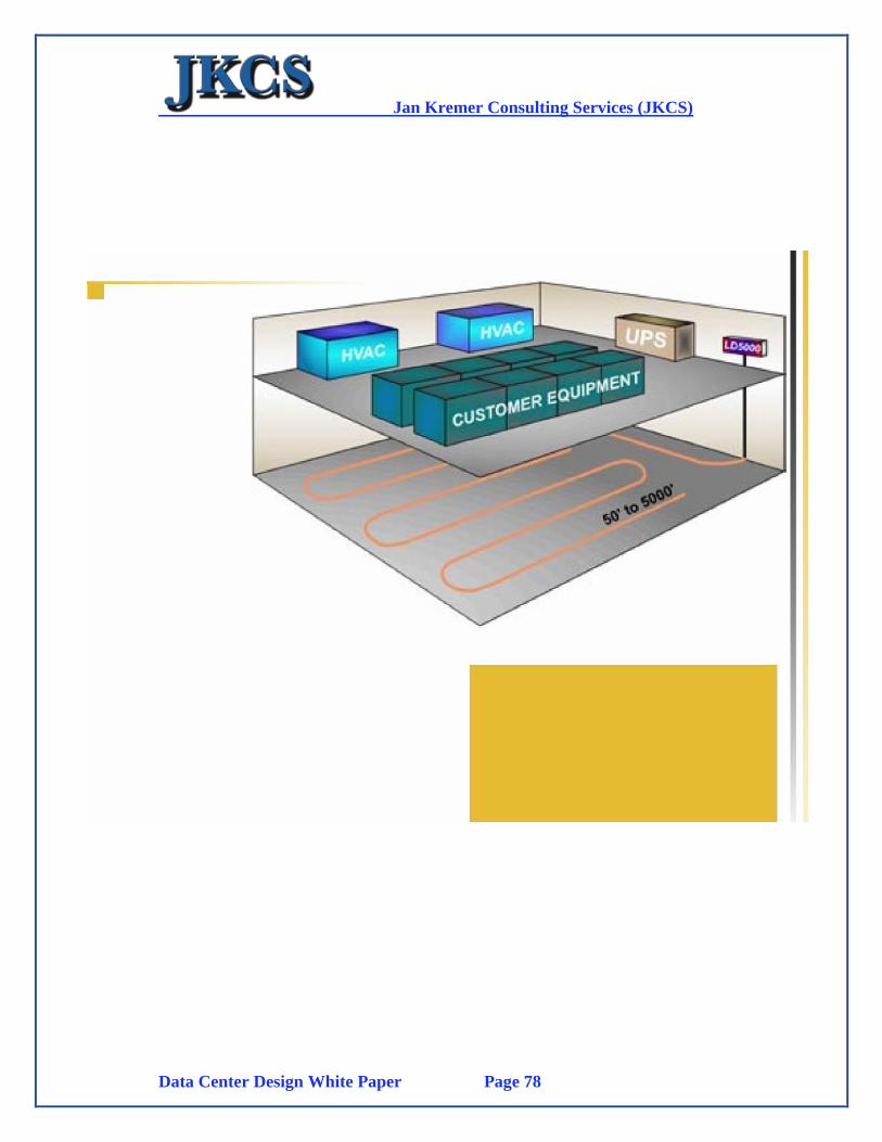
Jan Kremer Consulting Services (JKCS)
Data Center Design White Paper Page 78
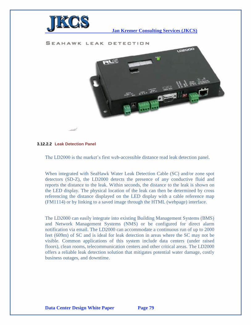
Jan Kremer Consulting Services (JKCS)
Data Center Design White Paper Page 79
3.12.2.2 Leak Detection Panel
The LD2000 is the market’s first web-accessible distance read leak detection panel.
When integrated with SeaHawk Water Leak Detection Cable (SC) and/or zone spot
detectors (SD-Z), the LD2000 detects the presence of any conductive fluid and
reports the distance to the leak. Within seconds, the distance to the leak is shown on
the LED display. The physical location of the leak can then be determined by cross
referencing the distance displayed on the LED display with a cable reference map
(FM1114) or by linking to a saved image through the HTML (webpage) interface.
The LD2000 can easily integrate into existing Building Management Systems (BMS)
and Network Management Systems (NMS) or be configured for direct alarm
notification via email. The LD2000 can accommodate a continuous run of up to 2000
feet (609m) of SC and is ideal for leak detection in areas where the SC may not be
visible. Common applications of this system include data centers (under raised
floors), clean rooms, telecommunication centers and other critical areas. The LD2000
offers a reliable leak detection solution that mitigates potential water damage, costly
business outages, and downtime.

Jan Kremer Consulting Services (JKCS)
Data Center Design White Paper Page 80
3.12.2.3 Leak Detection Cable
RLE patented SeaHawk Water Leak Detection Cable (SC) is used to reliably sense
the presence of water or any conductive liquid. SC is durable, easy to clean, fast
drying, and able to resist damage from most contaminants. The cable’s abrasion-
resistant polymer core increases its strength and durability. The cable is constructed
from non-conductive polymers which help eliminate false alarms commonly
associated with leak detection cable. When connected to a SeaHawk single or multi-
zone control panel, SC senses the presence of water in each zone and the panel
indicates which zone is in alarm.
When connected to a SeaHawk distance read panel, SC not only determines the
presence of a fluid, but also pinpoints the exact location of the fluid along the cable
route. Each SC connection to a SeaHawk panel requires a Leader Cable Kit (LC-
KIT). SC is available in standard and custom lengths. The cable’s ends terminate
with mating connectors which make installation and expansion of existing leak
detection systems quick and easy. SC offers a reliable leak detection solution that
mitigates potential water damage, costly business outages, and downtime.
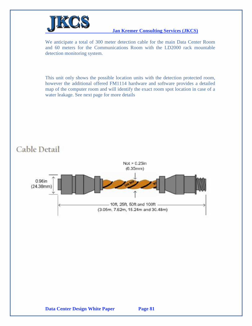
Jan Kremer Consulting Services (JKCS)
Data Center Design White Paper Page 81
We anticipate a total of 300 meter detection cable for the main Data Center Room
and 60 meters for the Communications Room with the LD2000 rack mountable
detection monitoring system.
This unit only shows the possible location units with the detection protected room,
however the additional offered FM1114 hardware and software provides a detailed
map of the computer room and will identify the exact room spot location in case of a
water leakage. See next page for more details
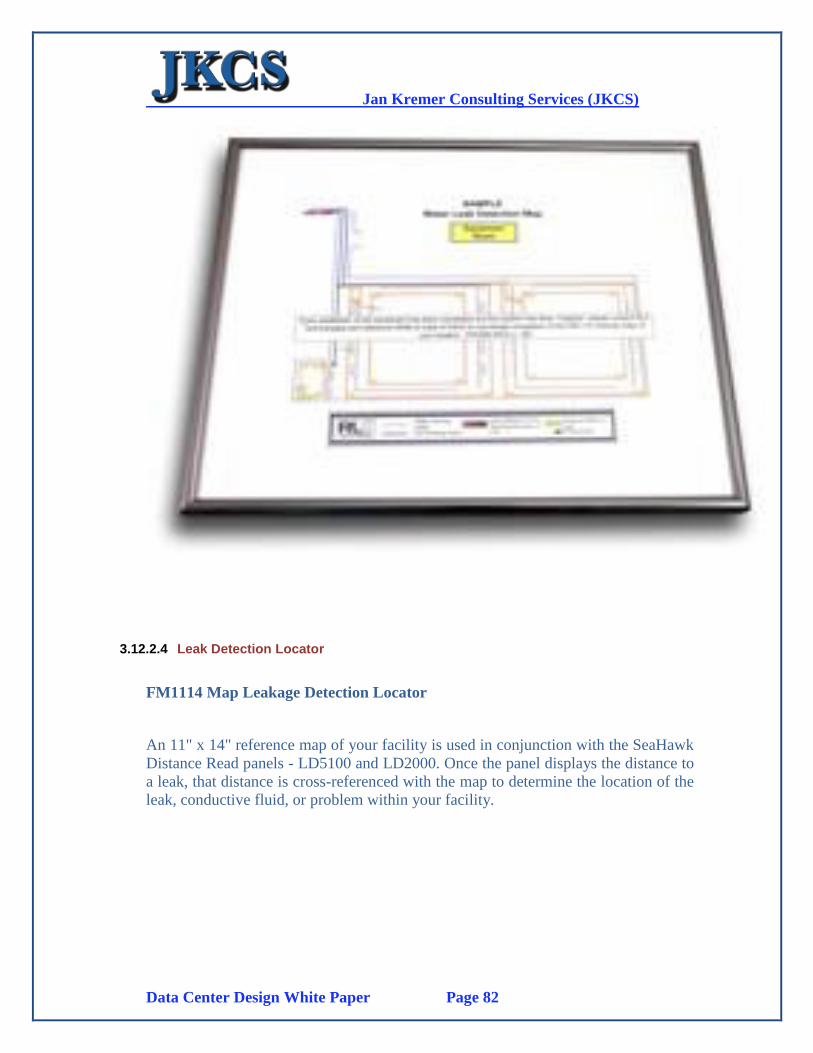
Jan Kremer Consulting Services (JKCS)
Data Center Design White Paper Page 82
3.12.2.4 Leak Detection Locator
FM1114 Map Leakage Detection Locator
An 11" x 14" reference map of your facility is used in conjunction with the SeaHawk
Distance Read panels - LD5100 and LD2000. Once the panel displays the distance to
a leak, that distance is cross-referenced with the map to determine the location of the
leak, conductive fluid, or problem within your facility.
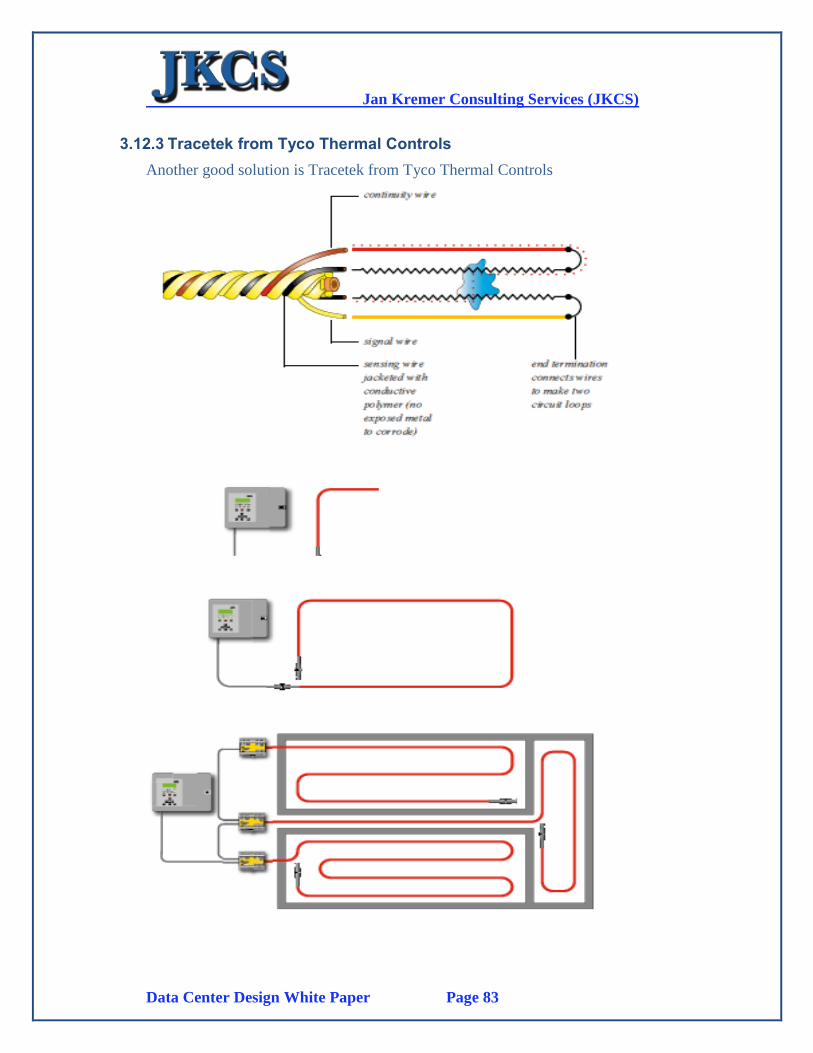
Jan Kremer Consulting Services (JKCS)
Data Center Design White Paper Page 83
3.12.3 Tracetek from Tyco Thermal Controls
Another good solution is Tracetek from Tyco Thermal Controls
Jan Kremer Consulting Services (JKCS)
Data Center Design White Paper Page 84
Unique sensing cable
Distributed sensing: by sensing liquid along its entire length, TraceTek cable
makes it possible to detect leaks at their source
Durable construction: small but rugged cable is extremely resistant to corrosion
and abrasion
o Dries and clears quickly: cable construction leaves virtually no place to
trap moisture Simple and sure detection circuit – that can also locate
Continual check of system integrity:
TraceTek cable uses a four-wire construction. Monitoring the two circuit loops
provides a continual and positive verification of system integrity.
Simple and sure detection: liquid creates a circuit between the sensing wires to
trigger an alarm –no moving parts, no calibration.
o Accurate location: a TraceTek locating system pinpoints (0.1% precision)
where liquid contacts the sensing cable. The locating module measures the
current and the voltage drop in the second sensing loop and simply applies
Ohm’s law (R=V/I)
o Clear indication: LEDs clearly indicate system status – monitoring, leak,
or fault.
Modular – for ease of design and installation
Standard lengths of TraceTek cable quickly plug together so you don’t need special
tools to install the system. The modular design also means that you can easily add to
the system in the future.
Flexible – with a choice of systems and interfaces to meet your needs
There’s a TraceTek system to meet your needs, whether you’re looking for a simple
detection system (for a small, isolated area) or for a complex, multi-branched
locating system. All TraceTek modules have relays to signal detection of an alarm
condition (for example, to a building management system).
Our locating system also displays the distance to the leak. Our microprocessor-based
alarm and locating module continues to monitor after a leak and alarms if any major
change occurs. It keeps a log of events and has built-in system wide diagnostic
functions. In addition to alarm relays, its interfaces include a 4 – 20 mA current
transmitter and an RS-232/RS-485 communications port.

Jan Kremer Consulting Services (JKCS)
Data Center Design White Paper Page 85
HP OpenView integration is established through the RLE Monitoring System which
integrates with BMS Systems and NMS Systems such as HP OpenView.
Jan Kremer Consulting Services (JKCS)
Data Center Design White Paper Page 86
3.13. Labeling
3.13.1 Introduction
We propose the standard TIA 606-A for labeling all data center elements such as:
Cabling
Patch Panels
PDU units
Racks and Contents
Cooling Units
Monitoring Panels
Etc.
All data is collected using a TIA-606-A compliant software/hardware system that
stores all collected and labeled data into a Database. See below for a short summary.
3.13.2 Features
Web-enabled Solution
Log-in Security
Full ANSI/TIA/EIA 606A Compliance
Documentation Wizards
Seamless Link With LabelMark™ Software
Spreadsheet import tool
Multi-view and multi-task capability
Import data from testers
User and Date Stamping on all Notes
Customizable Fields
Attachment Capabilities
Track Horizontal and Backbone Cabling, Termination Hardware, Assets,
Contacts, Fire Stopping, Pathways, Cable Splices, and much more!
Jan Kremer Consulting Services (JKCS)
Data Center Design White Paper Page 87
3.13.3 Benefits
Proper documentation allows you to quickly locate, review and correct network
issues.
Quickly export all your ID's for anything being tracked to Brady's Label Mark
label design software with little effort and time.
Minimal resources are needed to implement NetDoc. Brady experts are available
to help with expert training, support, and consulting work as needed.
All of your documentation, test results, drawings, and any other attachments you
need are at your fingertips in one secure location.
Staff members will be better able to manage all areas of your network by knowing
where equipment is located and what it is connected to, which will save time and
expenses.
3.13.4 Provides
Cable Management
Network Documentation
Asset Management
ANSI/EIA/TIA-606-A Complaint
Application(s): ANSI/EIA/TIA-606-A Compliant, Asset
Management, Cable Management, Network
Documentation
Operating System: Windows® 2000, XPWindows® 2000
Server, Windows 2003 Server
Printer Compatibility: 1244/1344 Series, InkJet/Laser Printers,
MVP Series, Tagus, TLS 2200®, TLS PC
Link™, Wraptor, X-Plus Series
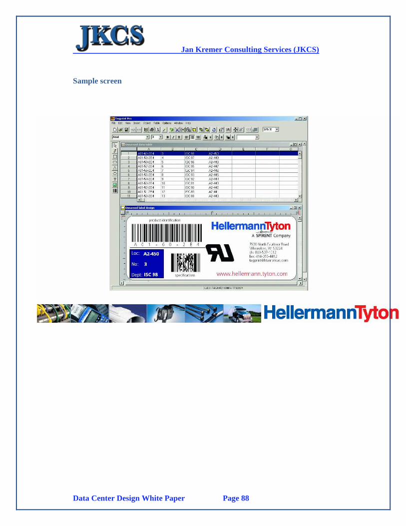
Jan Kremer Consulting Services (JKCS)
Data Center Design White Paper Page 88
Sample screen
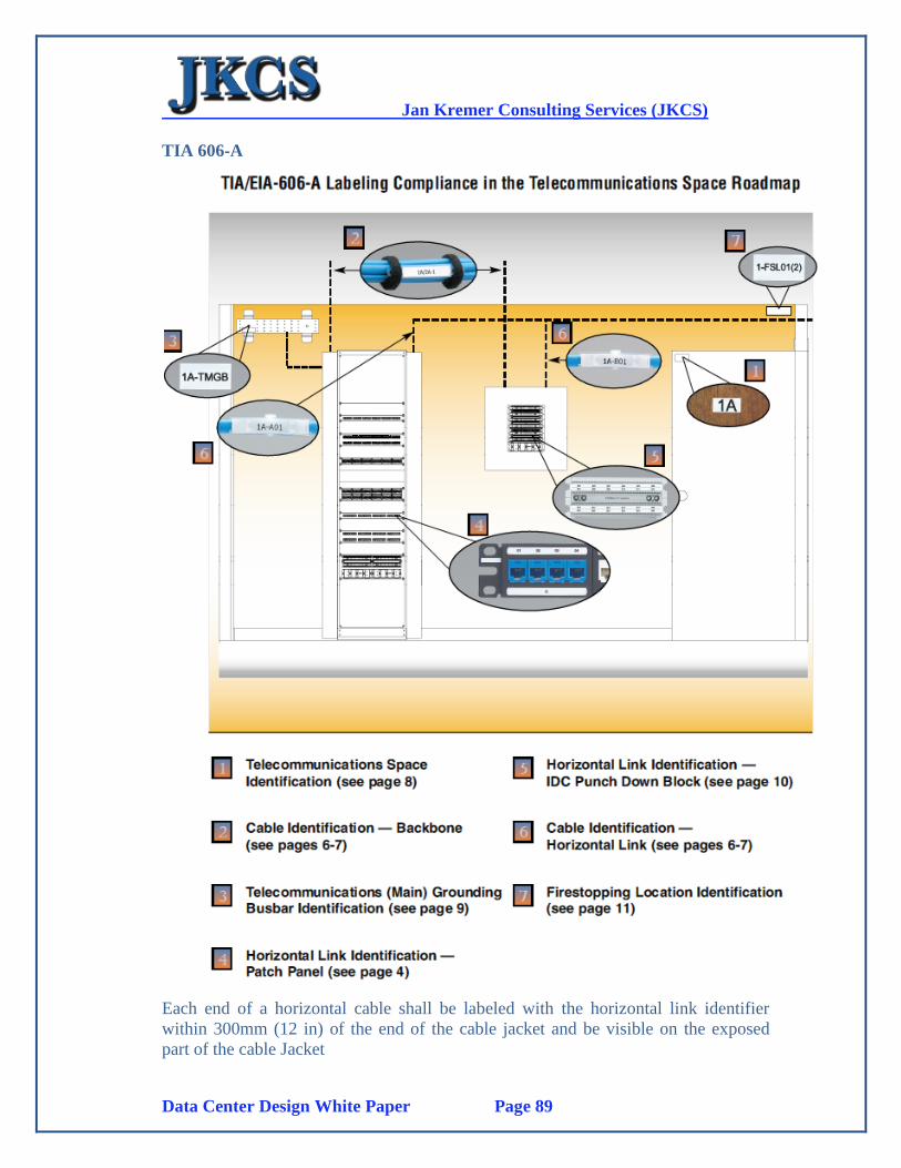
Jan Kremer Consulting Services (JKCS)
Data Center Design White Paper Page 89
TIA 606-A
Each end of a horizontal cable shall be labeled with the horizontal link identifier
within 300mm (12 in) of the end of the cable jacket and be visible on the exposed
part of the cable Jacket

Jan Kremer Consulting Services (JKCS)
Data Center Design White Paper Page 90
“Each individual telecommunications outlet & connector shall be labeled with the
horizontal link identifier. Labeling to appear on the faceplate, connector, or Mutoa”
(multi-user telecommunications outlet assembly)
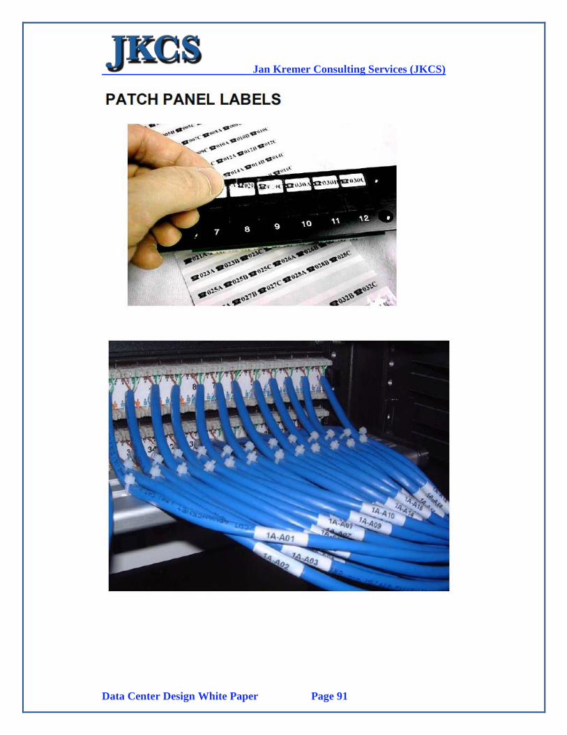
Jan Kremer Consulting Services (JKCS)
Data Center Design White Paper Page 91
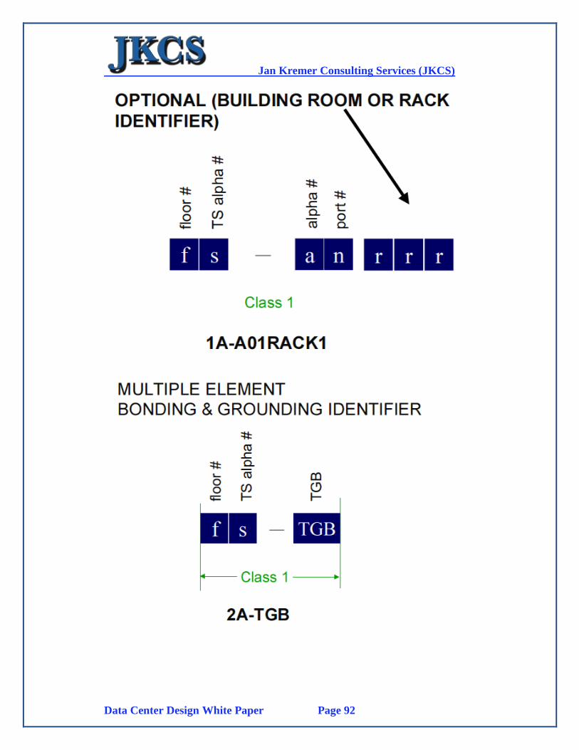
Jan Kremer Consulting Services (JKCS)
Data Center Design White Paper Page 92
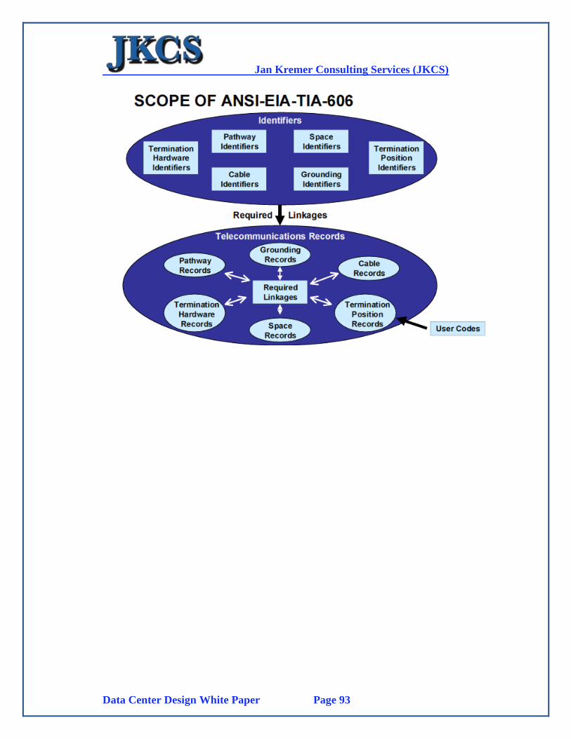
Jan Kremer Consulting Services (JKCS)
Data Center Design White Paper Page 93