Embed Size (px)
Citation preview

www.westernpowerinnovation.co.uk
Project FALCON FINAL REPORT – A WiMAX Based
Telecommunications System to Support Engineering Trials
08 September 2015

Project FALCON
Neither WPD, nor any person acting on its behalf, makes any warranty, express or implied, with respect to the use of any information, method or process disclosed in this document or that such use may not infringe the rights of any third party or assumes any liabilities with respect to the use of, or for damage resulting in any way from the use of, any information, apparatus, method or process disclosed in the document. © Western Power Distribution 2016 No part of this publication may be reproduced, stored in a retrieval system or transmitted, in any form or by any means electronic, mechanical, photocopying, recording or otherwise, without the written permission of the Future Networks Manager, Western Power Distribution, Herald Way, Pegasus Business Park, Castle Donington. DE74 2TU. Telephone +44 (0) 1332 827446. E-mail [email protected].
FINAL REPORT – A WiMAX Based Telecommunications System to Support Engineering Trials 2
Contents Executive Summary ............................................................ 6
1 Introduction and Overview ......................................... 7 1.1 Background 8 1.2 Approach to Knowledge Management 12 1.3 Scope 12 1.4 Document Structure 12 1.5 Acknowledgements 13
2 System Requirements ............................................... 14 2.1 High Level 15 2.2 Detailed Requirements 16
3 System Design and Planning ..................................... 19 3.1 System Overview 22
4 Integration, Installation & Commissioning ............... 44 4.1 Rollout of WiMAX Radio Capability to the WPD 11KV
Substation Network Trials Area 45 4.2 Radio Connectivity 49 4.3 Attached End-user Equipment Support 50 4.4 System Integration 51 4.5 Installation Working Practices and Methods 52 4.6 Antenna Mountings 62 4.7 Other Issues 63
5 Network Operations and System Monitoring ........... 66
5.1 Training 67 5.2 Monitoring of the Network 68 5.3 Network Management 73 5.4 Diagnostics 73
6 Maintenance & Remedial Work ................................ 79 6.1 Tolerance of Network Problems 80 6.2 Handling Problem Sites 80 6.3 Lines of Sight and Coverage 81

Project FALCON
FINAL REPORT – A WiMAX Based Telecommunications System to Support Engineering Trials 3
6.4 Interference and Restrictions 85 6.5 Transient Issues 91 6.6 Unresolved Issues 93
7 Network Security ....................................................... 95
7.1 Approach 97 7.2 Physical Security of Critical Infrastructure 97 7.3 Implications for Performance and Latency 98 7.4 Secure Network Segregation 98 7.5 Device Hardening 98 7.6 Management Plane Protection 99 7.7 Control Plane Protection 99 7.8 Security Governance 100 7.9 Substation LAN Security Design 100 7.10 IPSec Virtual Tunnel Interfaces 103 7.11 Head-end WAN Access 104 7.12 Head-end Traffic Segmentation 104 7.13 Primary substation WAN access 105 7.14 Secondary substation WAN access 105 7.15 Authentication, Authorisation and Auditing (AAA)
framework for Smart Grid 105
8 Latency and Throughput ......................................... 107 8.1 Measured Latency 108 8.2 Monitored Throughput 112
9 Equipment Integration ............................................ 115 9.1 Substation Equipment Types 117
10 Comparison to Existing Systems ............................. 128 10.1 Scanning UHF Radio 129 10.2 Broadband over Powerline (BPL) 130 10.3 Alternative and Complementary Technologies 131
11 Overall Project Conclusions .................................... 133 11.1 Specific Conclusions 134 11.2 Specific Recommendations 137 11.3 Reasons for Poor Radio Connectivity 139 11.4 Wider Application of WiMAX Technology for DNO
Communications 142 11.5 What Next for the FALCON WiMAX Network 143 11.6 Next Generation FALCON-Type Networks 144 11.7 WiMAX Frequency Regulatory Policy and Future
Plans 144
Appendices ..................................................................... 148 A FALCON Substation List 149
Figures Figure 1: Pico Call Structure of the FALCON WiMAX Network 17 Figure 2: Radio Planning Tool Output - FALCON Trials Area 22
Project FALCON
FINAL REPORT – A WiMAX Based Telecommunications System to Support Engineering Trials 4
Figure 3: FALCON Network Geographical Coverage Area 23 Figure 4: FALCON FAN Backhaul Schematic 24 Figure 5: PRTG WiMAX Secondard Nodes Clustered Around Base Stations 25 Figure 6: Airspan Airsynergy Base Station 26 Figure 7: Airsynergy Pole Mount Bletchley Primary 26 Figure 8: Typical Primary Site Components 27 Figure 9: Marlborough St Primary Site - Pole Top Configuration 28 Figure 10: Typical (Ground) Secondary Site Components 29 Figure 11: Typical Ground Based Secondary Site Installation 30 Figure 12: Cisco CGR1240 Router in Situ 30 Figure 13: FALCON Antenna on Cranked Pole 30 Figure 14: Cisco CGR1240 Router with Attached Equipment (Gridkey LVM) 30 Figure 15: FALCON Network Tiered Architecture 32 Figure 16: Cisco CGR2010 Primary Substation Rugged Router, Front View 33 Figure 17: Cisco CGS 2520 Rugged LAN Switch, Front View 34 Figure 18: Cisco CGR 1240 Secondary Substation Rugged Router 35 Figure 19: FALCON Head-end Network Infrastructure 38 Figure 20: Typical Primary Substation VLAN Connectivity 41 Figure 21: Head End Infrastructure VLAN Topology 42 Figure 22: FALCON Static Virtual Tunnel Interface (SVTI) 42 Figure 23: 15m Wood Pole Installation Work 47 Figure 24: Fully Installed Wood Pole at Bletchley Primary 47 Figure 25: LV Busbar Clamp Power Sourcing 61 Figure 26: Fuse with Auxiliary Power Socket 61 Figure 27: Typical FALCON Panel Antenna (1.4GHz WiMAX) 62 Figure 28: Granby Court Substation, Surrounding Trees 62 Figure 29: Antenna Pointing Options for Secondary Substations 65 Figure 30: Netspan (part) Node View 69 Figure 31: Netspan (part) Subscriber Station View 69 Figure 32: PRTG Top Level Device Based Network View 71 Figure 33: Willen Road Substation, SNMP Temperature Monitoring 73 Figure 34: Plot of UL CINR against RSSI All Substations 77 Figure 35: Plot of DL CINR against RSSI All Substations 77 Figure 36: Downlink CINR/RSSI Plot with Substations Identified 78 Figure 37: Long Term Signal Deterioration at Unisys Logistics Centre 83 Figure 38: PRTG Ping RTT Times at Malins Gate (Annual Plot) 84 Figure 39: PRTG Ping Response Times at The Linx, Bletchley 86 Figure 40: Netspan Registration Historyfor Moulsoe Church 88 Figure 41: Moulsoe Church Ping RTT Times Before and During Silverstone Week 89 Figure 42: Thorneycroft Lane Ping RTT Before & After Attenuation 90 Figure 43: Network Security Design 97 Figure 44: Network End-to-End Pathways 111 Figure 45: WAN Traffic at FALCON Head-end Router (365 days) 113 Figure 46: WAN Traffic at FALCON Head-end Router (30 days) 113 Figure 47: FALCON Network Top Protocols 114 Figure 48: P341 DAR Relay Support 117

Project FALCON
FINAL REPORT – A WiMAX Based Telecommunications System to Support Engineering Trials 5
Figure 49: Screen Shot of T200E Measurement Data Download 120 Figure 50: Sub.net Device - Configuration of FALCON Network IP Parameters 121 Figure 51: Sub.net Device - Real Time Parameter Display 121 Figure 52: Sub.net Device - Display of Recorded Measured Values 121 Figure 53: Sub.net Device - CSV File Download 121 Figure 54: Energy Storage Systems - Overview of Controller Devices 122 Figure 55: Energy Storage Systems - Site Controller Software 123 Figure 56: Energy Storage Systems - Battery Controller Software 124 Figure 57: Energy Storage Systems - Screenshot of DNP3 Dashboard Application on Site Controller PC 125 Figure 58: Tollgrade Lighthouse MV Sensor 126 Figure 59: Device Inter-connection for 11kV Overhead Line Dynamic Asset Rating Trial 127 Figure 60: WRC 2015 Options for 1.3 - 1.5GHz Bands 145 Figure 61: EUTC Spectrum Proposal 146 Figure 62: European Radio Spectrum Policy Programme 147

Project FALCON
FINAL REPORT – A WiMAX Based Telecommunications System to Support Engineering Trials 6
Executive Summary This document describes the telecommunications workstream of the FALCON Project and in particular presents the learning which has resulted from the design, rollout and subsequent operational activities. It is intended that the FALCON Project will inform the development of the future WPD telecommunications strategy as well as gathering the learning associated with the rollout and use of new communications technologies for the benefit of the wider utilities industry given that a number of elements in the FALCON communications system have been deployed for the first time in the UK and therefore presented significant learning opportunities. Our findings across a range of areas and activities bear out this initial expectation.
The primary role of the FALCON communications network is to allow monitoring and where necessary control of the engineering intervention techniques which the project trialled, enabling accurate data to be gathered from the field for analysis and use by other FALCON workstreams. The telecommunications system also facilitates the gathering of the passive monitoring data from the Low Voltage Monitoring devices widely deployed on the trials network.
The system was operated successfully in support of the trials and proved stable in use once a number of individual installation issues had been resolved. The IP architecture was flexible and the bandwidth available for the transmission of data proved more than sufficient for the needs of the network. The project concludes that WiMAX has proved to be a suitable radio technology for the FALCON application, giving high levels of control to the DNO when compared to other alternative candidate solutions. Failures to connect or to maintain stable links to substations in various circumstances have been understood and the reasons for, and solutions to these cases are presented in this report.
The WiMAX technology in use and in particular the operating frequencies were the subject of a specific dispensation from OFCOM and UK MoD to test the FALCON systems and the report includes a section from the JRC which discusses the future possibilities for further use of WiMAX frequencies in the UK.
WPD is currently exploring the potential to utilise the FALCON Telcos network and the experience gained during the project to test other technologies across the WPD area to determine the most suitable option for the future.

Project FALCON
FINAL REPORT – A WiMAX Based Telecommunications System to Support Engineering Trials 7
SECTION 1
1 Introduction and Overview

Project FALCON
FINAL REPORT – A WiMAX Based Telecommunications System to Support Engineering Trials 8
1.1 Background One of the major workstreams of the FALCON Project provided the design and deployment of a pilot for a radio based telecommunications infrastructure, the primary objective of which is to support the FALCON engineering trials area in Milton Keynes. Because of its experimental nature, a secondary objective for the project is to develop the basis of a ‘system blueprint’ through which to inform the industry in the event that a similar WiMAX radio based telecommunications infrastructure solution were to be rolled out elsewhere.
The FALCON Project itself deploys four technical engineering and two commercial intervention techniques, and combinations thereof, which are designed to resolve network constraints. These are used as alternatives to the more conventional intervention approach of “Traditional Reinforcement” which simply uprates overloaded assets to obtain a resolution. Not only were these new techniques deployed as field trials, they were also modelled in a computer simulation of the same area of the 11KV distribution network (by the SIM project workstream of FALCON).
The six remedial intervention techniques are:
1. Dynamic Asset Rating;
2. Automated Load Transfer;
3. Meshed networks;
4. Energy Storage;
5. Distributed Generation;
6. Demand Side Management.
The field equipment supporting the four engineering techniques (numbered 1 to 4 in the list above) utilise the new IP communications network to return monitored data to a control/oversight and data collection function, the commercial techniques do not require the same level of communications support.
1.1.1 The Current Communications Architecture To date and prior to FALCON, connectivity to the large and primary substations operated by DNO’s such as WPD has usually (though not always) been via UHF scanning radio. In this architecture, each substation communicates back to a local UHF tower using a send and receive pair of antennas. Each of these towers has a high-speed backhaul using a combination of kilostream, microwave and dedicated networks connecting back to data centres in WPD. The GE ENMAC DMS system (now known more properly as Power On Fusion or POF) is the heart of the control centre. This System communicates with a Remote Terminal Unit (RTU) in each of the large and primary substations, allowing for the monitoring and control of the high voltage electrical equipment. The POF system controls the dialogue with these substations, with each being polled on a typical ten second cycle.
More widely, the smaller secondary substations usually (to date) have had no communication capability. However in the limited number of locations where
Project FALCON
FINAL REPORT – A WiMAX Based Telecommunications System to Support Engineering Trials 9
communications have been deployed, a GPRS modem or unlicenced UHF radio is used to allow communications from the POF systems to the RTU. This has most commonly been for monitoring, but in a few secondary substations switching operations can be performed.
Where present, the communications has tended to be one-way, in the form of monitoring rather than control, and although the use of automated switchgear is increasing it is mainly served using the same technology.
1.1.2 A Possible New Approach to Communications Whilst the FALCON Project overall is not primarily focused on the communications network, which is largely a means to an end, it is nevertheless a vital part of the project as the technical intervention techniques all rely heavily on a secure and robust communication infrastructure in order to be evaluated fully by the project. Across the utility industry, a reliance on the communications network is inevitably becoming more of an imperative as the concept of the smart grid becomes reality. FALCON was therefore charged with investigating whether a WiMAX radio based system offers a viable means to implementing communications infrastructure to support the Smart Grid paradigm.
The key communications goals of the FALCON Project were identified as follows:
1. The design and deployment of a secure and reliable communications infrastructure that provides connectivity to the nine primary substations and the 200 secondary substations identified in the FALCON trials area. The following were specific requirements for the telecommunications infrastructure implementation:
a. The Communications network will transport both Monitoring and Control traffic for the FALCON intervention techniques;
b. The Internet Protocol (IP) will be used across the WAN and all the intervention techniques will deploy Ethernet and IP enabled equipment (or interface capability);
c. The FALCON Network will incorporate an Ethernet station bus but the process bus will be hardwired connections. This station bus provides communications between the IEDs and RTU where appropriate;
d. Once the new communications network has been proven, the existing monitoring and control in the primary substations and the secondary substations may be migrated (where already existing) from the UHF network on to the FALCON Network1;
e. For the Meshed network intervention technique a secondary goal of deploying Teleprotection over the FALCON communications network is to be designed;
f. The communications infrastructure should primarily be on a private network that is in the control of WPD and their partners.
1
This is a long term requirement, not a FALCON objective as in most cases the existing comms at 11KV is piloting other trials.

Project FALCON
FINAL REPORT – A WiMAX Based Telecommunications System to Support Engineering Trials 10
2. To build a secure communications network for FALCON that does not compromise the security policy of WPD;
3. To prepare a view of the communications system design so as to be able to provide material for a blueprint for how utilities might deploy a future communications infrastructure for the Smart operations.
1.1.3 Constraints on the FALCON WiMAX Deployment The FALCON Project had a number of objectives, not solely associated with the electrical engineering aspects of the trials, and when assessing the success of the FALCON telecommunications network implementation it should be remembered that this was a pilot proof of concept activity taking place in a limited trials area.
The FALCON WiMAX based telecommunications system implementation was cost and time limited and the radio solution adopted for the project was therefore necessarily constrained by a number of early design decisions made to accommodate these constraints. This included limiting the project to the use of WPD owned property for the siting of radio towers and other support infrastructure, and minimising possible planning delays by operating within permitted development rights. The former constraint effectively limited the geographical position of the main backhaul antenna sites to WPD Primary substations large enough to accommodate them, while the latter limited the height of these antennas. In addition, many secondary substations are located in out of the way positions and to some extent are even hidden away from view where possible to make them less visually obtrusive. With WiMAX being a line of sight or near line of sight technology best served by a clear uncluttered view to the basestation, this ultimately led to there being a small number of locations within the trials area where coverage was so poor that they had to be abandoned from the trials or data gathering exercises. Unfortunately the difficulties coincided in several places with the locations of some of the more important secondary substations involved in the trials, so alternatives had to be sought and remedial action taken. The constraints are summarised below:
As noted above, the decision was taken to avoid third party involvement and costs where possible and deploy equipment solely to WPD real estate (primary substations for the main backbone infrastructure). This naturally limited the geographic spread of the radio coverage as the usual maximum reliable working range for the WiMAX system in normal use is around 2km in most circumstances;
Only FALCON trials locations were chosen for communications equipment deployment. This was an entirely pragmatic approach adopted early in the project. There is however no reason why non-FALCON primary sites could not have been used for telecommunications backhaul infrastructure. This would have improved the reach and spread of the communications network;
To avoid having to engage with and be delayed by the local council planning process it was decided to operate within the envelope of permitted development rights which permits towers of up to 15m height to be used without reference to planners. This of course limited the height and therefore reach of the antennas on the main base stations;

Project FALCON
FINAL REPORT – A WiMAX Based Telecommunications System to Support Engineering Trials 11
The means of raising the antennas to the selected 15m height above ground was chosen to be standard wood poles. While this provided a quick and cheap solution with in-house experience in deployment, it did mean that any pole top maintenance work needing to be carried out thereafter required the use of a MEWP for access. In anticipation of the need to avoid such access being required to the pole top in all cases, the main power breakers for the pole head equipment were installed much lower down near the base of the pole (to which cables had to be run). These poles attracted little adverse comment from neighbours which might not have been the case with metal lattice towers had these been used instead;
The project did not utilise some extant inter-primary fibre connections to form part of the connectivity which just happened to be available (linking Bradwell Abbey, Childs Way and Bletchley primaries) as this was considered to be counter to the investigative brief of the FALCON project and would have added little to the learning. The option was considered when connectivity options were being reviewed.
Because of the above, network coverage was somewhat limited from the outset and the project found that a number of secondary substation sites could either not be connected as a result or else had varying degrees of connection difficulties. This would not have been the case if the network had been organised to ensure connectivity based on previous learning rather than being constrained by time and cost. On the positive side for the project, this did mean that it was necessary to carry out a lot of investigative work to understand the situation on the ground for a number of problem cases. This approach led to the gathering of significant amounts of learning, presented in this report, which may be incorporated into adapting the approach for future deployments.
The FALCON Project required the rollout of monitoring and intervention equipment to around 200 electricity distribution substations. These were chosen from the subject trials area in Milton Keynes, an area containing around 800 secondary substations in total, and these sites were chosen early in the project without reference to their potential for radio coverage. The substation selection criteria was thus in the context of the wider FALCON objectives and radio coverage was a secondary consideration to selecting the appropriate substations for the primary FALCON objectives.
The data traffic was envisaged and designed to include control as well as monitoring data, so speed (latency) was an important consideration in the telecoms design. The physical carrier was chosen to be based on a WiMAX radio solution. The 1.4 & 3.5 GHz frequencies are currently largely vacant and have been used by the MoD who are potentially relinquishing full control and reservation of these bands and had granted their use for the period of the FALCON Project on a temporary Authority to Test licence.
The project was also required to observe an operating constraint forbidding use of the 3.5GHz frequency during the British Grand-Prix at Silverstone as this was also being used for the event. We note here that going forward, should the frequency become available and taken up for utilities use, such restrictions would not be acceptable for BaU - but permissions may be granted on a case by case basis where it did not compromise the effectiveness of the DNO.

Project FALCON
FINAL REPORT – A WiMAX Based Telecommunications System to Support Engineering Trials 12
1.2 Approach to Knowledge Management Learning was gathered through all phases of the Telecommunications system design, deployment and operations and documented as the information was obtained. The key learning target areas were captured very early on, in some detail in certain subjects, and a number of subject domains were identified in key areas, with information gathered as the project progressed. The details obtained for the learning points were noted at the same time as they arose in order to ensure that the information was as complete as possible, but a further ongoing source of information was a master site rollout management spreadsheet which was maintained from the very start of the site installations. This spreadsheet was organised by site and included the main site reference details as well as rollout notes which were mined for information in the later project phases.
1.3 Scope This report covers the Telecommunications workstream only. Reference is made in a number of places to documents and findings in the related Engineering Trials workstream which the communications system principally supports. One particular area of crossover between these two areas is the trials equipment/communications network integration.
1.4 Document Structure The main sections of the telecommunications workstream final report address the following areas:
Introduction and Overview;
System Requirements;
System Design and Planning;
Integration, Installation & Commissioning;
Network Operations and System Monitoring;
Maintenance & Remedial Work;
Network Security;
Latency and Throughput;
Equipment Integration;
Comparison to Existing Systems;
Overall Project Conclusions.
The project history and technical findings covering these main subject areas are presented in the sections which follow. The content of the main sections when each subject is discussed seeks to address the following points as and where applicable:
What did we set out to learn?
How did we go about it?
How successful were we?

Project FALCON
FINAL REPORT – A WiMAX Based Telecommunications System to Support Engineering Trials 13
What would we do differently if the work were to be repeated?
The cover photograph shows the WPD/Surf Telecoms Radio Tower at Little Horwood to the immediate South West of Milton Keynes which terminates the microwave link from Bradwell Abbey and is the junction point between the FALCON network and the rest of the WPD telecommunications system.
1.5 Acknowledgements The FALCON Project acknowledges the assistance of the JRC in the UK in relation to issues and advice concerning the use of the WiMAX radio spectrum and official policy in this regard. The JRC has also contributed to this document in section 11.4.
We acknowledge the permission of Project Partners Cisco to allow the re-use of a number of extracts from the design sections and a number of diagrams taken from the Cisco High Level Design for the FALCON telecommunications system.
We are also grateful to the UK MoD for providing dispensation to test the FALCON communications solution using the WiMAX frequency bands.
We acknowledge the permission of Paessler AG to use screenshots from the PRTG network monitoring tool.
We acknowledge the permission of Airspan to use screenshots from the Netspan radio network monitoring tool.

Project FALCON
FINAL REPORT – A WiMAX Based Telecommunications System to Support Engineering Trials 14
SECTION 2
2 System Requirements

Project FALCON
FINAL REPORT – A WiMAX Based Telecommunications System to Support Engineering Trials 15
2.1 High Level The FALCON Project was set up to find a means to address the communication requirements for Smart Grid Communications Networks which might be applicable to any of the UK Electricity Distribution Network Operators. The Primary Goal was to ensure the Communications Network was designed and built to ensure all of the Intervention Methods of the FALCON Project are supported in full. A secondary goal was to design the Communications Network to ensure future Bandwidth and Protocols were catered for. The Design was also to be scalable so as to allow for possible regional or even nationwide implementation as well as introducing new technologies for Smart Grid communications not currently used within the Electricity Industry.
These high-level communication requirements for the FALCON network translated into the following to level objectives:
Delivery of a private network;
A radio based solution is required;
No additional fibre or pilot wires may be installed;
All communications to be layered over Ethernet and IP;
A resilient design is required for the overall communication WAN infrastructure. The FALCON Project does not require resilient router and switch configurations in each substation however, as this would impose a significant additional cost and accommodation overhead, and single endpoint failures can be tolerated;
A lack of resilience in one part affects the resilience of the whole system;
No single site failure should be able to take down multiple sites;
GPRS is not considered sufficiently reliable to be used as a primary access mechanism or as a backup;
Redundant control centre backhaul points will be used;
Teleprotection over the FALCON network was to be trialled in an additional work item using IEC61850 GOOSE multicast messages;
All sites to have robust security in place using physical access control (specifically on ports) with E2E encryption via IPSec;
The devices being considered in the trial were to communicate only on IPv4. As part of an additional piece of work looking at the target Architecture, IPv6 was to be factored in. However for the FALCON network design this was out of scope. The infrastructure deployed was however IPv6 capable as future proofing.
The following practical considerations were also taken into account:
Use of Wood Poles in place of steel masts;
Height selection for substation poles;
Local planning authority planning restrictions;
Frequency restrictions and benefits;

Project FALCON
FINAL REPORT – A WiMAX Based Telecommunications System to Support Engineering Trials 16
Allocation of and reuse of MoD Spectrum, negotiating and working with the JRC and OFCOM;
Existing telecoms network back haul availability and capacity;
Existing Infrastructure availability;
Use of DNO assets for telecoms infrastructure;
Network capability to transport all protocols transparently;
Establishment of suitable Network Management solutions, protocols and procedures;
Design network security for prevention of cyber-attack;
Admin security for authorised users on Network;
Network equipment accommodation requirements;
Cost considerations for network build assets;
Use of DNO staff to reduce build costs;
Design and build of Lab for network configurations and evaluation of plant interfacing;
Facilitation of future maintenance access and procedures;
Notification of proposals to neighbours and interested parties to reduce the possibility of holdups later in the build programme;
Antenna installations at Secondary substations, installation and design options;
Antenna installations on Pylons for network access and Back Haul;
Earthing requirements of telecoms plant at primary and distribution substations;
Contractor and third party staff, substation access and authorisations;
Primary substation accommodation design;
Power requirements at primary and distribution substations;
Training and knowledge dissemination of new technology equipment to Telecoms Staff.
2.2 Detailed Requirements This section provides more detail on the specific design themes and requirements identified for implementation on the FALCON telecommunications workstream. The high level requirements include those relating to security, bandwidth and latency, while existing UHF based solution are not considered suitable for smart grid applications due to limitations in these areas.
Based on the high level system requirements an IP communications solutions choice and WiMAX communications technology were chosen for the implementation of the FALCON Project. This allows monitoring and control of the intervention techniques and can also potentially be used to form the basis for a future WPD communications architecture blueprint.
Some of the requirements evolved or were modified through the lifetime of the project.

Project FALCON
FINAL REPORT – A WiMAX Based Telecommunications System to Support Engineering Trials 17
2.2.1 Uplink Connectivity The Primary Substations connect via Airspan WiMAX access nodes and iBridge backhaul connectivity to one of two main radio aggregation sites, these locations are then backhauled over traditional communications technologies to the data centre.
The Primary Substations have a pico-cell capability which provides connectivity to the Secondary Substation sites.
Figure 1: Pico Call Structure of the FALCON WiMAX Network
Source: Cisco HLD
2.2.2 Resilience Resilience was built into the WiMAX architecture for the Primary Substations. No specific WAN resilience was required for Secondary Substations for the trials as this is essentially uneconomic given the lower number of properties affected on each feeder. In any case some of the connected equipment operates on a store and forward basis and this capability is assessed as providing an adequate level of resilience given the value at risk.
Load balancing was not a specific requirement. At the Head-end in Tipton, dual routers were initially considered, however it was decided that because the system only had a single backhaul connection this would not yield any great advantage. It might have been possible to have added dual Head-end routers for resilience, however the experience of the Project has been that Head-end router issues that have been seen were software related and easily managed. Nevertheless, for a future project and certainly for operations it is recommended that full resiliency is desirable, but clearly this has to be assessed according to the individual system requirements.
In terms of geographic redundancy (for a FALCON type network this would effectively mean the inclusion of two Head-ends) this capability, while initially considered, was remove due to cost/complexity and the fact WPD had no spare capacity on the backhaul network to the alternate Head-end site that had been proposed.
Project FALCON
FINAL REPORT – A WiMAX Based Telecommunications System to Support Engineering Trials 18
WAN backup using GPRS or other public radio technologies was not required for the FALCON network, although alternatives were considered during later project phases (refer to Section 10.3).
2.2.3 WAN Segmentation There was no requirement for segmentation of the traffic over the WAN. There was also no requirement for traffic segmentation within the Data Centre. All traffic is delivered via a single Gigabit Ethernet interface at each of the data centre locations. The FALCON network is separated by firewall from the WPD corporate network.
2.2.4 WAN Security All traffic is encrypted for ease of configuration using IPSec. However the effect of large amounts of PMU traffic on the router throughput needed to be checked to ensure that monitoring and control traffic was not adversely affected. IPSec is used with a basic hub and spoke topology. All encryption tunnels are terminated at the Head-end. This document includes in Section 7 a detailed explanation of security considerations and explains the design adopted by the project.
2.2.5 Availability LAN redundancy was not a requirement for the FALCON Project.
2.2.6 IP Addressing Requirements The requirement in terms of network addressing was for a readily repeatable deployment solution lending itself to replication over a large number of similar (though not identical) substation environments. The scheme required all substation devices to use a fixed IP address. Fixed IP address management and allocation was achieved using a master database spreadsheet.
The IP addressing uses the RFC1918 address ranges. All site configurations have the same temple. Thus the same configuration and IP addressing scheme is applicable to all the intervention techniques and can be deployed in all substations in a similar fashion as required. The IP address ranges were standardised using subnetting.
2.2.7 Port Security For layer 2 LAN segments MAC address filtering was implemented and controlled by a Radius database. This was deployed using 802.1x and MAC auth bypass functionality. WPD already used this policy.
802.1X admission control was not implemented due to the substation devices not being compliant with this technology and Cisco Standard LAN security best practices were used for LAN ports within the Substation. All unused ports were shut down and had to be actively enabled prior to being used.

Project FALCON
FINAL REPORT – A WiMAX Based Telecommunications System to Support Engineering Trials 19
SECTION 3
3 System Design and Planning

Project FALCON
FINAL REPORT – A WiMAX Based Telecommunications System to Support Engineering Trials 20
The design phase of the project was led by Surf Telecoms Ltd, WPD’s independent Telecommunications arm, working closely with partners and subcontractors Cisco and Airspan to define the overall IP network architecture. A primarily radio based IP network was planned for the FALCON Project as this offered significant flexibility and openness to the sort of future requirements envisaged for smart grid type network functionality under consideration on FALCON, where only limited physical connectivity options were available for the pre-existing facilities. With reference to the requirements above, further design considerations included bandwidth and throughput with a design that would minimise inherent latency while providing security and resilience and which was both proven where possible and available “off-the-shelf”.
Early on in the design process, Cisco engaged Airspan with whom they had worked previously in the USA on similar platforms and technologies. Airspan were identified as being a centre of radio product excellence who not only had a ready backhaul radio solution (AirSynergy) based on 3.5GHz radio, but also had a Cisco compatible (and field tested) 1.4 GHz WiMAX module compatible with the Cisco CGR router family identified as the main equipment for FALCON substation access points. The design therefore crystallised around this basic core equipment set for the physical implementation.
In the FALCON design, the Milton Keynes FALCON trials area electricity distribution network is served by an IP based telecommunications infrastructure which mirrors it to a large degree. There are eight2 distribution primary substations which were chosen to host Airspan Airsynergy telecommunications backhaul infrastructure. These telecommunications enabled primaries are interconnected, with the interconnections converging via Airspan iBridge radio units on two aggregation nodes at Bradwell Abbey and Horwood radio tower (which although part of the network is not itself a power distribution site). At Horwood, the ultimate FALCON communications aggregation point, all traffic joins the main Surf Telecoms Ltd. backhaul spine network serving WPD and is onward routed to/from control and monitoring elements at Tipton in the West Midlands.
The list of electricity distribution primaries in the greater trials area, which were potentially available for use by FALCON, is as shown below. Those which were actually used for communications infrastructure backhaul (around 50% of the available total) are shown in bold text. As noted elsewhere, based on FALCON outcomes, we can state with some certainty that the use of additional primaries from the list below would have improved coverage possibilities for the benefit of the secondary sites. Based on this list there were certainly more primaries that could have been used on FALCON:
Stony Stratford;
Shenley Wood;
Kiln Farm;
2
A ninth Primary at Winslow is not part of the backhaul 3.5GHz infrastructure but served largely as if it were a Secondary substation location, though uses an Airspan CPE access router rather than Cisco CGR 1240 device.

Project FALCON
FINAL REPORT – A WiMAX Based Telecommunications System to Support Engineering Trials 21
Bradwell Abbey;
Eldergate;
Portway;
Childs Way;
Bletchley;
Victoria Road;
Newton Road;
Secklow Gate;
Fox Milne;
Kingston;
Fen Farm;
Wavendon Gate;
Marlborough Street;
Newport Pagnell;
Wolverton;
Winslow (not backhaul comms)
With a radio solution the prime consideration will always be coverage and ensuring that this is maximised in the substation locations. Theoretical radio coverage was mapped by Airspan using radio planning tools, specifically the Airspan preferred planning utility Mentum Planet. This extended over the trials area and from this the WiMAX base cell deployment strategy was defined. Limited drive around tests employing a pump up mast were conducted both to verify the model (limited tests) and later and more widely, to check out those sites which were difficult to connect and use effectively. The FALCON trials area coverage map is reproduced below in Figure 2.

Project FALCON
FINAL REPORT – A WiMAX Based Telecommunications System to Support Engineering Trials 22
Figure 2: Radio Planning Tool Output - FALCON Trials Area
3.1 System Overview The WiMAX radio network implemented for the FALCON Project covers a large part of the urban area of Milton Keynes and additionally extends to the southwest into a more rural landscape. This was done intentionally to allow the trials of both underground and overhead electrical distribution components and gave the additional advantage of testing both types of environment in the telecommunications context. Refer to Figure 3 below.

Project FALCON
FINAL REPORT – A WiMAX Based Telecommunications System to Support Engineering Trials 23
Figure 3: FALCON Network Geographical Coverage Area
The overall network consists of a pre-existing backhaul spine (mainly microwave based) operated by Surf Telecoms Ltd. for WPD which converges on the Tipton “Head-end”, and an access point to this at Horwood Radio Tower in the South West region of the FALCON trials area. Horwood has two main base stations acting as a root for the FALCON FAN backhaul network on 3.5GHz and onto which a number of inter-primary FALCON 3.5GHz links converge. In addition, Little Horwood Radio Tower also terminates a microwave link to the Bradwell Abbey Primary (and bulk supply point) at which point the 3.5GHz backhaul link to Marlborough St (relayed also to Newport Pagnell) converges. Horwood thus forms a central aggregation node in the network aggregating the microwave radio traffic from Bradwell Abbey as well as the traffic from the substations parented directly from Horwood with access via the three Horwood WiMAX access nodes.
In end-to-end terms, the primary substation Airspan Airsynergy picocells connect to the Airspan iBridge units which backhauls individual picocell traffic back to a further iBridge node at either Horwood tower or Bradwell Abbey substation as described above. Airsynergy sector base stations (WiMAX Nodes) are hardwired at the pole top to a dedicated iBridge node, which connects back to the iBridge nodes at Horwood or Bradwell Abbey sites. Bradwell Abbey then connects to Horwood via a WPD provided

Project FALCON
FINAL REPORT – A WiMAX Based Telecommunications System to Support Engineering Trials 24
Ethernet based microwave radio system. Once traffic is aggregated at Horwood, it is forwarded via a microwave radio links within the WPD network, terminating at Tipton.
The overall FALCON backhaul is illustrated in Figure 4 below, a “map” image taken from the live network monitoring system PRTG.
Figure 4: FALCON FAN Backhaul Schematic
On the diagram in Figure 4, the microwave link (physical link) corresponds with the line shown connecting the Cisco ME3600 switches at Bradwell Abbey and Horwood Radio Tower (Logical link). All the other links are implemented as 3.5Ghz WiMAX inter-primary connections effected using the Airspan AirSynergy base stations. It is seen, by referring to the above diagram, that there are three main branches to the backhaul as implemented:
1. Newport Pagnell Feeder Terminal (FT) relayed via Marlborough St relay and FT to Bradwell Abbey Feeder Base (FB) and onwards to Little Horwood Radio Tower via microwave link;
2. Childs Way, Secklow Gate and Fox Milne FT, connecting to Little Horwood FB1;
3. Bletchley and Newton Road FT connecting to Little Horwood FB2.
The rest of the radio network at the lowest levels consists of the secondary substations which are clustered around their local primary substation (interestingly, in an analogous

Project FALCON
FINAL REPORT – A WiMAX Based Telecommunications System to Support Engineering Trials 25
way to the structure of the electrical distribution network) and which are connected using a spread of three main frequencies (contained in a scan list - 1432.5 MHz, 1437.5 MHz and 1442.5 MHz) in the 1.4GHz WiMAX band. Most of the primary sites (but not Child’s Way or Bradwell Abbey primaries which each have one, and Horwood which has three) have two WiMAX nodes pointing in different directions acting as access to the backhaul for these secondary locations. As described elsewhere in this document, when establishing connectivity at a given secondary site the antenna is panned around on the different access frequencies in turn until a usable signal is found, being the best of those investigated. A section of the overall network topology with this lowest level of granularity exposed is illustrated in Figure 5 below, also taken from the live network monitor system PRTG.
Figure 5: PRTG WiMAX Secondard Nodes Clustered Around Base Stations
Source: PRTG Network Monitor
Project FALCON
FINAL REPORT – A WiMAX Based Telecommunications System to Support Engineering Trials 26
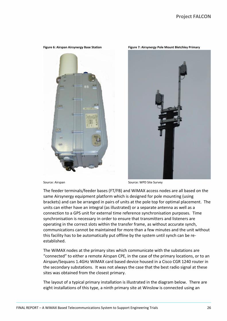
Figure 6: Airspan Airsynergy Base Station Figure 7: Airsynergy Pole Mount Bletchley Primary
Source: Airspan Source: WPD Site Survey
The feeder terminals/feeder bases (FT/FB) and WiMAX access nodes are all based on the same Airsynergy equipment platform which is designed for pole mounting (using brackets) and can be arranged in pairs of units at the pole top for optimal placement. The units can either have an integral (as illustrated) or a separate antenna as well as a connection to a GPS unit for external time reference synchronisation purposes. Time synchronisation is necessary in order to ensure that transmitters and listeners are operating in the correct slots within the transfer frame, as without accurate synch, communications cannot be maintained for more than a few minutes and the unit without this facility has to be automatically put offline by the system until synch can be re-established.
The WiMAX nodes at the primary sites which communicate with the substations are “connected” to either a remote Airspan CPE, in the case of the primary locations, or to an Airspan/Sequans 1.4GHz WiMAX card based device housed in a Cisco CGR 1240 router in the secondary substations. It was not always the case that the best radio signal at these sites was obtained from the closest primary.
The layout of a typical primary installation is illustrated in the diagram below. There are eight installations of this type, a ninth primary site at Winslow is connected using an

Project FALCON
FINAL REPORT – A WiMAX Based Telecommunications System to Support Engineering Trials 27
Airspan CPE (not a WiMAX enabled Cisco CGR 1240 router) as if it were a secondary site as this location has no backhaul routing role and consequently no Airspan Airsynergy terminals, though it does have engineering trials equipment deployed.
Figure 8: Typical Primary Site Components
Source: FALCON Project
The pole top configuration of antennas and Airspan Airsynergy units shown in the above diagram in schematic form is also shown in the image below taken of the actual field deployment at Marlborough Street Primary. This location acts as a relay node for the Newport Pagnell Primary which was found to be “over the horizon” for Microwave or 3.5GHz communications via any other route to the aggregation sites on the FALCON backhaul. The figure shows the Airspan Airsynergy units (FT and relay node), WiMAX nodes (x2) and high gain square antennas pointing in opposing directions at Bradwell Abbey aggregation node and Newport Pagnell (relayed). Also shown is the scanning radio mast offset from the other WiMAX equipment. For maintenance purposes this array needed to be accessed using a MEWP.

Project FALCON
FINAL REPORT – A WiMAX Based Telecommunications System to Support Engineering Trials 28
Figure 9: Marlborough St Primary Site - Pole Top Configuration
Source: Airspan
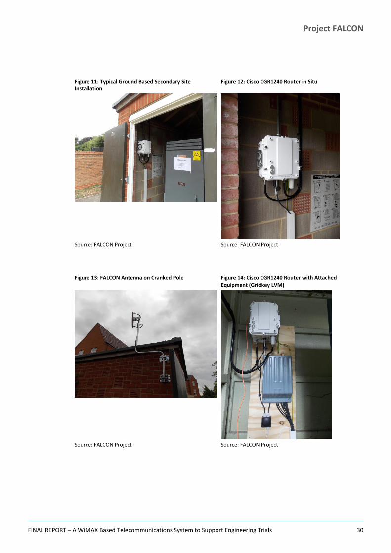
For the secondary distribution substations a typical site layout for a ground mounted enclosed location is illustrated below. A similar equipment set is deployed to both pole and ground mounted compound locations though the mounting and deployment details are clearly site dependent as all sites tend to be unique in their construction, size, layout and aspect. Nevertheless, the secondary site communications solution is largely standard, varying only in terms of the placement of equipment and matters such as cable length, antenna height and bearing.

Project FALCON
FINAL REPORT – A WiMAX Based Telecommunications System to Support Engineering Trials 29
Figure 10: Typical (Ground) Secondary Site Components
Source: FALCON Project
The following pictures were taken during the installation and rollout phase of the Project and illustrate typical secondary site installations.
Project FALCON
FINAL REPORT – A WiMAX Based Telecommunications System to Support Engineering Trials 30
Figure 11: Typical Ground Based Secondary Site Installation
Figure 12: Cisco CGR1240 Router in Situ
Source: FALCON Project Source: FALCON Project
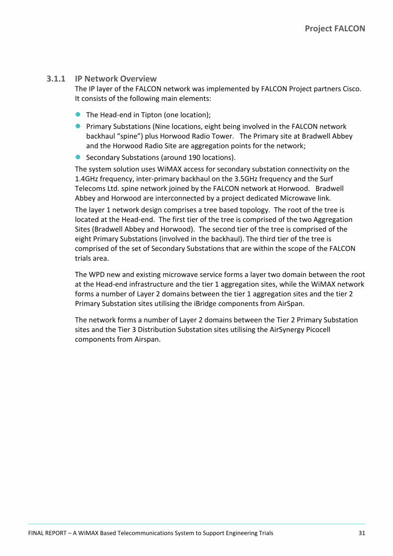
Figure 13: FALCON Antenna on Cranked Pole Figure 14: Cisco CGR1240 Router with Attached Equipment (Gridkey LVM)
Source: FALCON Project Source: FALCON Project
Project FALCON
FINAL REPORT – A WiMAX Based Telecommunications System to Support Engineering Trials 31
3.1.1 IP Network Overview The IP layer of the FALCON network was implemented by FALCON Project partners Cisco. It consists of the following main elements:
The Head-end in Tipton (one location);
Primary Substations (Nine locations, eight being involved in the FALCON network backhaul “spine”) plus Horwood Radio Tower. The Primary site at Bradwell Abbey and the Horwood Radio Site are aggregation points for the network;
Secondary Substations (around 190 locations).
The system solution uses WiMAX access for secondary substation connectivity on the 1.4GHz frequency, inter-primary backhaul on the 3.5GHz frequency and the Surf Telecoms Ltd. spine network joined by the FALCON network at Horwood. Bradwell Abbey and Horwood are interconnected by a project dedicated Microwave link.
The layer 1 network design comprises a tree based topology. The root of the tree is located at the Head-end. The first tier of the tree is comprised of the two Aggregation Sites (Bradwell Abbey and Horwood). The second tier of the tree is comprised of the eight Primary Substations (involved in the backhaul). The third tier of the tree is comprised of the set of Secondary Substations that are within the scope of the FALCON trials area.
The WPD new and existing microwave service forms a layer two domain between the root at the Head-end infrastructure and the tier 1 aggregation sites, while the WiMAX network forms a number of Layer 2 domains between the tier 1 aggregation sites and the tier 2 Primary Substation sites utilising the iBridge components from AirSpan.
The network forms a number of Layer 2 domains between the Tier 2 Primary Substation sites and the Tier 3 Distribution Substation sites utilising the AirSynergy Picocell components from Airspan.

Project FALCON
FINAL REPORT – A WiMAX Based Telecommunications System to Support Engineering Trials 32
Figure 15: FALCON Network Tiered Architecture
Source: Cisco FALCON HLD
3.1.1.1 Head-end Infrastructure The Head-end of the network is located in Tipton and houses the Head-end router, network servers and onward connectivity via firewall to the WPD operational network. Thus:
Network Management Systems
– SolarWinds NMS
– PRTG Network Monitor
– Airspan NMS (Netspan)
– NOC PC (GUI Programs)
Access Control
– TACACS

Project FALCON
FINAL REPORT – A WiMAX Based Telecommunications System to Support Engineering Trials 33
Security
– Zone Based Firewalls (ZBFW) in tunnel termination routers
Network Devices
– Tunnel Termination Routers
– LAN Switching
The Head-end infrastructure interfaces with the WPD firewalls via a dedicated Layer 3 connection (Local Head-end VLAN’s are not extended to the WPD Firewalls). The Head-end routers at Tipton main office will also connect to the NMS servers via a GE fibre link between Tipton office and Ocker House where the servers are located.
3.1.1.2 Primary Site Infrastructure In the primary distribution substations WAN integration is provided by the Cisco CGR2010 router which is connected wirelessly via WiMAX to the AirSynergy node within the same substation via a dedicated Airspan CPE (presented as an Ethernet connection to the CGR2010).
The Substation LAN consists of a station bus only. All grid devices are hardwired to sensors.
Figure 16: Cisco CGR2010 Primary Substation Rugged Router, Front View
Source: Cisco FALCON HLD
The CGR2010 supports 2 Gigabit Ethernet ports and provides connectivity for the substation switch (CGS2050, see below) and the uplink to the Airspan WiMAX network. The additional GRWIC slots are available for future additional port capacity using an ESM module or for additional functionality (such as a 2g/3g card for backup).
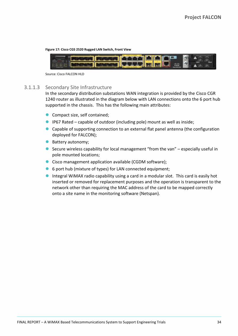
The primary site CGS2050 LAN switch provides both fibre and copper access ports to support attachment of engineering and monitoring equipment.
Both the CGR 2010 router and CGS2050 switch are rugged devices which compared to classical routers and switches are more suitable for deployment to harsh environments.
Project FALCON
FINAL REPORT – A WiMAX Based Telecommunications System to Support Engineering Trials 34
Figure 17: Cisco CGS 2520 Rugged LAN Switch, Front View
Source: Cisco FALCON HLD
3.1.1.3 Secondary Site Infrastructure In the secondary distribution substations WAN integration is provided by the Cisco CGR 1240 router as illustrated in the diagram below with LAN connections onto the 6 port hub supported in the chassis. This has the following main attributes:
Compact size, self contained;
IP67 Rated – capable of outdoor (including pole) mount as well as inside;
Capable of supporting connection to an external flat panel antenna (the configuration deployed for FALCON);
Battery autonomy;
Secure wireless capability for local management “from the van” – especially useful in pole mounted locations;
Cisco management application available (CGDM software);
6 port hub (mixture of types) for LAN connected equipment;
Integral WiMAX radio capability using a card in a modular slot. This card is easily hot inserted or removed for replacement purposes and the operation is transparent to the network other than requiring the MAC address of the card to be mapped correctly onto a site name in the monitoring software (Netspan).

Project FALCON
FINAL REPORT – A WiMAX Based Telecommunications System to Support Engineering Trials 35
Figure 18: Cisco CGR 1240 Secondary Substation Rugged Router
Source: Cisco High Level Design for FALCON
3.1.2 Addressing Schema In the substations all devices use a statically assigned IP address. Dynamically assigned IP addresses were only utilised on VLAN 7 for supporting an engineering laptop for which address allocation is via the DHCP protocol. The DHCP server is provided by the local CGR 2010 and restricted to the VLAN 7 subnet allocation only. This support was provided for the Engineers laptops so that they did not have to be concerned with IP addressing considerations when moving between locations.
The IP addressing scheme that was used is derived from the RFC1918 /12 address ranges. Actual IP addresses are omitted from this issue of the Report.
Use Required Subnets Summary Mask
Substations 1 x /26 per substation /26 per substation
Project FALCON
FINAL REPORT – A WiMAX Based Telecommunications System to Support Engineering Trials 36
Use Required Subnets Summary Mask
(8 subnets of /29) each per substation)
Unused Reserved For Future Use
Head-end /28 x 5 /24
IPSEC SVTI /31 per IPSEC Tunnel /23
Backhaul /26 x10 /24
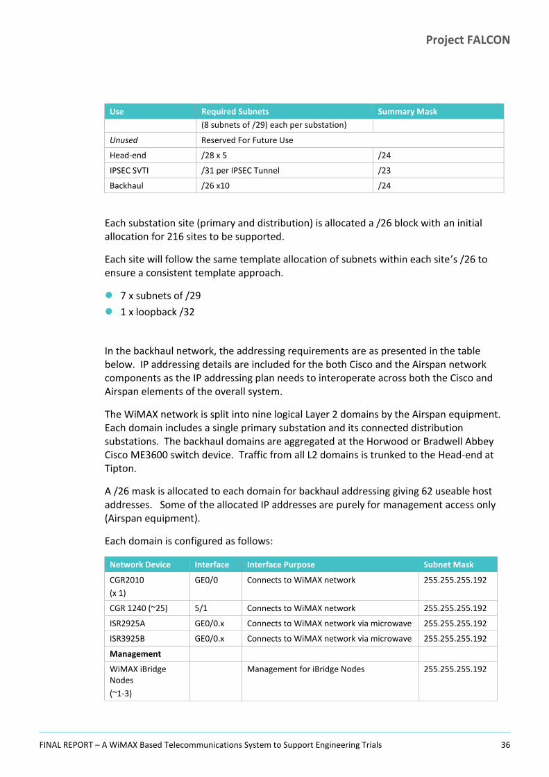
Each substation site (primary and distribution) is allocated a /26 block with an initial allocation for 216 sites to be supported.
Each site will follow the same template allocation of subnets within each site’s /26 to ensure a consistent template approach.
7 x subnets of /29
1 x loopback /32
In the backhaul network, the addressing requirements are as presented in the table below. IP addressing details are included for the both Cisco and the Airspan network components as the IP addressing plan needs to interoperate across both the Cisco and Airspan elements of the overall system.
The WiMAX network is split into nine logical Layer 2 domains by the Airspan equipment. Each domain includes a single primary substation and its connected distribution substations. The backhaul domains are aggregated at the Horwood or Bradwell Abbey Cisco ME3600 switch device. Traffic from all L2 domains is trunked to the Head-end at Tipton.
A /26 mask is allocated to each domain for backhaul addressing giving 62 useable host addresses. Some of the allocated IP addresses are purely for management access only (Airspan equipment).
Each domain is configured as follows:
Network Device Interface Interface Purpose Subnet Mask
CGR2010
(x 1)
GE0/0 Connects to WiMAX network 255.255.255.192
CGR 1240 (~25) 5/1 Connects to WiMAX network 255.255.255.192
ISR2925A GE0/0.x Connects to WiMAX network via microwave 255.255.255.192
ISR3925B GE0/0.x Connects to WiMAX network via microwave 255.255.255.192
Management
WiMAX iBridge Nodes
(~1-3)
Management for iBridge Nodes 255.255.255.192

Project FALCON
FINAL REPORT – A WiMAX Based Telecommunications System to Support Engineering Trials 37
Network Device Interface Interface Purpose Subnet Mask
WiMAX AirSynergy Nodes
(~1-3)
Management for Airsynergy Nodes 255.255.255.192
ME3600 Loop0 Management interface on WiMAX network aggregation switch
255.255.255.255
At the primary substations, a /29 subnet is allocated for each VLAN, providing 6 useable IP addresses per VLAN.
The first address within each of the /29 subnets is used for the CGR2010 sub interface on the trunk link. The remaining 5 addresses are then available for the addressing of endpoint devices.
The following IP addressing scheme has been allocated to the network devices within the Primary Substations:
Network Device Interface VLAN Tag VLAN Purpose Subnet Mask
CGR2010
(x9)
Loop0 - Mgt 255.255.255.255
GE0/1.2 2 RTU 255.255.255.248
GE0/1.3 3 DAR Relays 255.255.255.248
GE0/1.4 4 PMU 255.255.255.248
GE0/1.5 5 Protection Relays 255.255.255.248
GE0/1.6 6 Tollgrade Aggregator 255.255.255.248
GE0/1.7 7 Engineering Laptop 255.255.255.248
CGS2520
(x9)
VLAN1 1 Mgt 255.255.255.248
At the secondary substations, a /29 subnet has been allocated for each interface, providing 6 useable IP addresses per subnet, sufficient for the amount of equipment deployed at these locations.
The first address within each of the /29 subnets is used for each of the individual CGR 1240 physical interfaces. The remaining 5 addresses are then available for the addressing of endpoint devices that are connected to the given interface on the CGR 1240.
The following IP addressing scheme was allocated to the network devices within the Secondary Substations:
Network Device Interface VLAN Tag Purpose Subnet Mask
CGR 1240
(x200)
Loop0 - Mgt 255.255.255.255
FE2/1 - DA Device 1 255.255.255.248
FE2/2 - Future Use 255.255.255.248

Project FALCON
FINAL REPORT – A WiMAX Based Telecommunications System to Support Engineering Trials 38
Network Device Interface VLAN Tag Purpose Subnet Mask
FE2/3 - RTU 255.255.255.248
FE2/4 - Future Use 255.255.255.248
FE2/5 - Future Use 255.255.255.248
FE2/6 - Future Use 255.255.255.248
The Head-end infrastructure is comprised of four VLANs in a flat network architecture.
The Head-end LAN is interconnected with the WPD firewall, thereby providing the primary and secondary substations connected to the FALCON network with onward connectivity to WPD control centres and potentially, other components within the WPD enterprise network environment.
The diagram below shows the basic IP address requirements. A /24 mask is allocated by the FALCON Head-end infrastructure. This /24 network range is further subnetted to provide /28 subnets for the four required VLANs and the Layer 3 connection between the WPD IR firewall and the FALCON network’s Head-end infrastructure.
Figure 19: FALCON Head-end Network Infrastructure
Source: Cisco FALCON HLD

Project FALCON
FINAL REPORT – A WiMAX Based Telecommunications System to Support Engineering Trials 39
A dedicated VLAN500 subnet is used to connect to the Surf Telecoms Ltd. 3560 router for NTP (see Section 3.1.7).
The Head-end infrastructure network devices are configured as follows:
Network Device Interface VLAN Tag VLAN Purpose Subnet Mask
ISR3925A Loop0 - 255.255.255.255
GE0/1.200 200 Management 255.255.255.240
GE0/1.300 300 DA Traffic 255.255.255.240
GE0/1.400 400 Radius 255.255.255.240
GE0/1.500 500 NTP 255.255.255.240
ISR3925B Loop0 - 255.255.255.240
GE0/1.200 200 Management 255.255.255.240
GE0/1.300 300 DA Traffic 255.255.255.240
GE0/1.400 400 Radius 255.255.255.240
GE0/1.500 500 NTP 255.255.255.240
Catalyst 3750X VLAN200 200 Management 255.255.255.240
WPD IR Firewall xEy - DA Traffic 255.255.255.240
Surf Telecom 3560
VLAN500 500 NTP 255.255.255.240
3.1.3 Routing Within the FALCON network, static routing was used on all network devices as the architecture lends itself to static routing (being a hub and spoke architecture with no redundant paths). Whilst dynamic routing protocols, including OSPFv2 are available, static routing was used for reasons of simplicity.
Each of the primary and secondary substation sites has a default route configured with the next hop configured towards the Head-end infrastructure being set as the (IPSec) tunnel interface.
The Head-end infrastructure routers (i.e. ISR3925A and ISR3925B) have aggregated static routes for each remote site with a next hop set towards the WiMAX backhaul network domains (each backhaul network domain having its own sub-interface). The IP addressing scheme allocated for each remote site (primary & secondary) provides a summary aggregate route to minimize the administrative configuration requirements that are associated with static routing.
Within the Head-end infrastructure VLANs, the traffic that traverses from the FALCON network towards the WPD enterprise systems behind the WPD firewall is routed over from the FALCON network ISR3925s towards the WPD firewall via VLAN 300 within the Head-end infrastructure, again through the use of static routing.

Project FALCON
FINAL REPORT – A WiMAX Based Telecommunications System to Support Engineering Trials 40
3.1.4 Use of DHCP Dynamic allocation of IP addresses takes place on the substation LAN infrastructure in order to support the interconnection of engineering laptops on VLAN 7. A DHCP server is enabled for the subnet that provides connectivity for the engineering laptop at each primary substation. The DHCP server is configured with the relevant DNS & Default Gateway details for the engineering laptop.
A DHCP server instance is configured locally on the CGR2010 at each of the primary substations. No centralized DHCP services are available for the Engineering Laptops on the FALCON network.
3.1.5 Use of VLANs VLAN’s are required in the Primary substations to separate intervention technique devices and also in the Head-end infrastructure.
Primary Substation VLAN Assignments are as shown in the table below. A VLAN database supports the nominated switch ports on the Cisco CGS2520 switch.
VLAN Use Switch Ports
1 Default Management
2 RTU FE 0/17
3 DAR Relays FE 0/1-3
4 PMU FE 0/4-5
5 Protection relays FE 0/6-7
6 Tollgrade Aggregator FE 0/18-19
7 Engineering Laptop FE 0/243
Each intervention technique has been allocated a separate VLAN and IP subnet to mimic the allocation template at the secondary substations (e.g. one IP address subnet per interface). This was done to provide, as far as possible, a common design template and IP address allocation structure. VLANs are used at primary substations for segregating local traffic.
3
Engineer will contact Surf NMC for port enablement as per operational procedures.

Project FALCON
FINAL REPORT – A WiMAX Based Telecommunications System to Support Engineering Trials 41
Figure 20: Typical Primary Substation VLAN Connectivity
Source: Cisco FALCON HLD
In the Secondary Substations the CGR 1240 does not support the creation of layer 2 based VLANs. All of the ports on the CGR 1240 are layer 3 based ports. The port can be configured with a unique IP address (a fixed IP address permanently assigned to that port) and provide a subnet gateway for any device that is connected to the port.
In the Head-end Infrastructure, the VLAN Assignments are required to be separated into a small number of VLAN’s in order to segregate the management traffic, DA traffic and the network services traffic (NTP & Radius) that is routed to or from WPD IR and the Surf Telecoms Ltd. networks.
The following diagram shows the Head-end infrastructure VLAN topology:

Project FALCON
FINAL REPORT – A WiMAX Based Telecommunications System to Support Engineering Trials 42
Figure 21: Head End Infrastructure VLAN Topology
Source: Cisco FALCON HLD
The tunnel termination routers utilize the Zone-Base Firewall (ZBFW) function to permit only the specific traffic detailed by the network design.
VLAN Use Notes
200 Management Airspan + SNMP + Tacacs
300 DA Traffic Grid Device traffic
400 FALCON Services Radius
500 Surf Telecom Services NTP
3.1.6 IPSec Tunnels Each CGR router has a static virtual tunnel interface (SVTI) configured to the Head-end router using IPSEC to secure the traffic. The overall security approach and architecture is described in Section 7. Each SVTI requires a /31 IP address subnet.
Figure 22: FALCON Static Virtual Tunnel Interface (SVTI)

Project FALCON
FINAL REPORT – A WiMAX Based Telecommunications System to Support Engineering Trials 43
Source: Cisco FALCON HLD
When an IPSec VTI is configured, encryption occurs in the tunnel. Traffic is encrypted when it is forwarded to the tunnel interface. Traffic forwarding is handled by the IP routing table, and dynamic or static routing can be used to route traffic to the SVTI as it appears as a separate interface (such as ‘Tunnel0’) in the routing table. After packets arrive on the inside interface, the forwarding engine switches the packets to the VTI, where they are encrypted. The encrypted packets are handed back to the forwarding engine, where they are switched through the outside interface.
3.1.7 NTP The Network Time Protocol (NTP) service is provided by the Surf Telecom Ltd. network to support the operation of the FALCON system. NTP synchronizes the time of a computer client or server to another server or reference time source, such as a radio, satellite receiver, or modem. NTP provides client accuracy that is typically within milliseconds on LANs, and up to a few tens of milliseconds on WANs, relative to the synchronised primary server.
NTP runs over UDP, which in turn, runs over IP. All NTP communication uses UTC, which is essentially the same as Greenwich Mean Time (GMT). NTP synchronizes time-stamps between the NTP server and all routers configured for NTP. The synchronization of time-stamps allows events from multiple routers to be correlated when system logs are created.
The CGR routers deployed for FALCON each need to access an NTP server before the IPSec tunnel used for the session can be configured and used. This must be done so that the certificate expiration date can be accurately validated. This necessarily means that the NTP server IP address must belong to the provisioning routing plan that is shared with the IPSec traffic routing plan from CGR perspective. FALCON uses three Symmetricom NTP servers hosted by Surf Telecoms Ltd., which work by peering with the Surf 3560 at Tipton.
All devices in the primary and distribution substations will require access to an NTP server, so the Surf Telecoms NTP servers are also visible to the FALCON network. The recommended option was to configure the ISR3925s to synchronise with the NTP server and allow the primary / secondary distribution substation routers to ‘peer’ with their parent ISR3925 within the Head-end infrastructure. This allows access to the Surf Telecoms NTP servers to be restricted to the Head-end infrastructure routers.
Project FALCON
FINAL REPORT – A WiMAX Based Telecommunications System to Support Engineering Trials 44
SECTION 4
4 Integration, Installation & Commissioning

Project FALCON
FINAL REPORT – A WiMAX Based Telecommunications System to Support Engineering Trials 45
This section covers the main field rollout activities carried out by the FALCON Project to deploy the telecommunications solution to the network and prove its operation.
4.1 Rollout of WiMAX Radio Capability to the WPD 11KV Substation Network Trials Area The initial rollout plan of radio capability to sites involved with the FALCON trials was based on a theoretical radio coverage plan provided by Radio contractor/suppliers Airspan and spanned the area containing the candidate substations. There was some flexibility as to which sites were chosen for the trials as the brief for the project directed that the required intervention technique capabilities be deployed at a number of suitable places on the electricity distribution network. With over 800 substations available to choose from in the core trials network area and only 200 needing to be included in the trials, this allowed for some freedom in the selection process which was mainly based on characteristics of the electrical network and customer distribution details. For example, low voltage monitoring (LVM) needed to be deployed to a range of locations representative of the various customer categories4. This would allow comparison at a range of load locations of different types between actual load profiles gathered by monitoring and the predictions of the energy model.
At this early stage, with the preliminary list of sites chosen, deployment of equipment could then commence. This included both communications equipment in the form of routers and antennas as well as the electrical distribution network units required for the trials and served by the communications system (such as switches, temperature sensors and batteries). This programme of work continued at both the primary locations (where the base station backhaul nodes of the communications network were located) and the distribution substations in parallel in what was hoped would be a rapid deployment. This approach did however mean that the core network was not always available early enough to allow substations to be tested as each was deployed and while obvious with hindsight we now consider this to be a key learning point.
Additionally, the project also utilised initial deployment fitting teams who were not radio specialists and therefore some sites needed to be revisited, sometimes on multiple occasions, in an ongoing programme of work necessary to make them reliable enough for their intended use. The project was able to draw on partner organisations to provide expert support.
In a small number of cases, sites from the preliminary rollout list needed to be abandoned and replaced by other candidates because of unsuitable radio coverage or detrimental local conditions. In this respect the initial broad coverage analysis was clearly not the whole story in terms of being a completely accurate predictor of radio coverage in very
4
There were 32 Customer Categories in total based on the total number of customers and the proportion of customers that were domestic at a given location.

Project FALCON
FINAL REPORT – A WiMAX Based Telecommunications System to Support Engineering Trials 46
specific subject areas. Some of the possible reasons for this are discussed elsewhere in this Report.
Once the main 3.5GHz WiMAX backhaul communications backbone was in operation with all the antennas in the primaries pointed as per the theoretical radio plan, the secondary substations could then be brought fully online, tested and commissioned in a rolling programme of works extending over several months. Because of the approach described above, the project found that around 30% of the deployed sites initially exhibited connection difficulties at some level or other with around half of those requiring significant rectification effort or even abandonment (around 5% overall fell into the latter bracket)5. In the same interval, the project also refined its network monitoring tools, procedures and expertise and this meant that the team view of the health of the network evolved and improved considerably. As a result of this improved view and diagnostic capability, revisits to sites previously assumed to be good on the basis of their radio health stats became necessary when it was discovered that additional indicators at the IP connectivity level suggested the presence of residual issues which would have left the affected substations unusable without suitable remedial action being taken. There is further discussion of this in sections below.
An additional problem seen by the project was that the substation CGR routers had been prepared and tested in batches in the lab staging area, in some cases a long time prior to actually being deployed. It also transpired that there were some incremental configuration elements added to the stored routers later on. This all meant that elementary mistakes and non-standard entries were sometimes made in specifying and loading up equipment configurations which then required additional effort later on to diagnose and rectify. With hindsight the project concludes that it is much better to do such repetitive tasks by scripting these, to do these carefully just once and to keep extensive records and track the work.
As noted above, the work of equipping substations with supporting infrastructure (mounting plates, trunking, antenna mountings, power feeds), configuring and later installing communications (and electrical intervention and monitoring equipment), connecting these all up, checking the systems out (testing) and supporting/monitoring/managing the sites) was done by separate fitting teams with management coordination, and these teams did not always have radio installation training. As experience was gained, the project found that this work therefore required careful tracking of the progress of each substation and to that end reliable, regularly supplied information from the fitting (and other) teams should be considered a mandatory requirement of such programmes.
The site installation activities were as follows:
5
A note on these percentage figures. The boundary between an issue being considered as the finessing of an installation matter and being a true issue requiring a more in depth investigation is not clear cut, so these numbers are for guidance only. Individual site details are available in Appendix A.

Project FALCON
FINAL REPORT – A WiMAX Based Telecommunications System to Support Engineering Trials 47
Primary Substation Works
Wood Pole installations were carried out by WPD engineering staff mainly at weekends to fit in with existing work load commitments;
Figure 23: 15m Wood Pole Installation Work Figure 24: Fully Installed Wood Pole at Bletchley Primary
Source: Airspan Source: Airspan
Wood poles were used as they offered very cost effective solution to the project and were augured into the ground close to the primary buildings within the primary compounds;
Battery Charger Installations within the Primary Substations were carried out by WPD contractors Team Simoco who provided fitting teams with electrical qualifications;
Airspan Airsynergy Radios were configured by Airspan with installation being carried out by Beacon Comms;
DC / AC inverter wiring and equipment set up and installed by Surf Telecoms Ltd. Engineering staff;
Airspan CPE configured and tested by Airspan with Installation being carried out by Team Simoco fitting teams in association with Surf Telecoms Ltd. Engineering staff;
Cisco Routers Installed by Team Simoco and Surf Engineering Telecoms Ltd. staff with configuration from low level design templates and conduct of end-to-end commissioning tests done with support from the Cisco Partner Team.

Project FALCON
FINAL REPORT – A WiMAX Based Telecommunications System to Support Engineering Trials 48
Distribution Substation Works
CGR 1240 Router Installation carried out by Team Simoco;
Square plate antenna and RF feeders installed by Team Simoco;
Interface configuration installed by Surf Telecoms Ltd. and Cisco Partner Team in conjunction with Falcon WPD Distribution Contractors;
AC wiring installed in PVC conduit by WPD smart metering and Team Simoco fitting teams;
Cat5 Data wiring in PVC conduit installed by WPD smart metering staff on secondment to the FALCON Project;
Basic initial antenna panning was carried out by the Team Simoco fitting teams when the first kit installations were being done;
Radio optimisation was carried out retrospectively by both project team staff and more extensive works were done by Beacon Comms whenever it was identified that there was very poor radio connectivity at a given location and especially where these locations involved active trials deployments. The Beacon Comms work included raising antennas to extended heights (around 6m where possible) and panning on different scan lists to find best usable signals. This was done in cooperation with centralised monitoring based in the FALCON Lab which inspected the results of adjustments in near real time and fed back to the beacon installation team on the ground;
Integration Lab Works
Network Switches and routers were installed and configured by the Cisco Partner Team. These were borrowed from the Head-end resilient units;
Airspan VPN and remote access was set up by Surf Telecoms Ltd. Engineering Teams with assistance by external Consultants;
Project Servers and application software loaded on them were set up by project partners and manufacturers and configured by both these teams and the projects own staff.
General
Network Management Servers were supplied by WPD IR (Information Resources) team and specialist software installed by vendors such as Cisco, Airspan and Gridkey but also by the project staff;
Airspan Netspan Manager, server supplied by WPD and software supplied and installed by Airspan;

Project FALCON
FINAL REPORT – A WiMAX Based Telecommunications System to Support Engineering Trials 49
PRTG IP Network Management, server supplied by WPD IR with software being supplied and installed by Cisco Partner Team.
4.2 Radio Connectivity A specific learning point which emerged from the FALCON deployment work and subsequent checkout and operations relates to the radio network, and concerns the need to establish reliable end-to-end communications early on in the rollout and commissioning phase. The FALCON trials involved some two hundred specifically equipped 11kV substations in the trials area. The project found that around 65% of these sites came up and communicated over the WiMAX link quite readily with little or no intervention, while the remaining 35%, some 70 locations, fell into a number of categories in respect of problems or delays encountered and these are broadly listed below. Any organisation carrying out a similar rollout operation might wish to anticipate these problems when planning their own programme of work:
Site surveys identified the need to undertake rectification work requiring HV outages, which had to be planned in so as to minimise impacts on consumers, affecting the installation dates. Other unforeseen issues also arose and around 6 sites (3% of the total) were affected by such issues. Examples included:
– Straightening a leaning pole before telecoms equipment could be safely installed;
– Putting in place certain site specific arrangements (such as agreeing with landowners to gain access over waterlogged fields).
Fitting crews should be coordinated with radio engineers (or else use specialist companies) to ensure that antennas are mounted in the most suitable location at a site and pointed at the most appropriate/best primary base station based on received signal parameter monitoring. Some 30 sites (15% of the total) needed revisiting to adjust mounting brackets placed inappropriately on wooden poles or buildings. The lesson here is that inter-team coordination early on in the fitting process saves checks and revisits later, and this was clearly evidenced by improved performance later in the programme once the learning had led to the approach being modified;
A programme of work was undertaken through 2014 to improve radio connectivity using 6m poles deployed at all main trials sites and additionally at those with particular and ongoing difficulties. This programme of work covered some 35 sites, around 17% of the total number of substations involved in FALCON;
A number of other locations needed additional fine tuning to the best bearing for the local primary base station;
A number of sites had too strong a signal and required the fitting of attenuators to reduce the signal strength or eliminate an interfering signal (all CPE primary locations and a further 8 locations, or around 4% of substations);
An early view needs to be taken in respect of radio connectivity by doing drive around tests and using pump-up mast surveys. It was found, where fitting had been done prior to widespread radio connectivity existing, that longer masts were often required for more difficult sites when these were then made live at a later date. Around 15
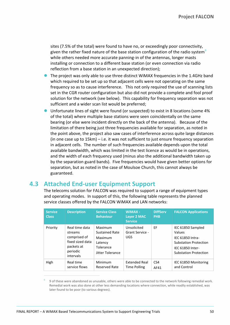
Project FALCON
FINAL REPORT – A WiMAX Based Telecommunications System to Support Engineering Trials 50
sites (7.5% of the total) were found to have no, or exceedingly poor connectivity, given the rather fixed nature of the base station configuration of the radio system6 while others needed more accurate panning-in of the antennas, longer masts installing or connection to a different base station (or even connection via radio reflection from a base station in an unexpected direction);
The project was only able to use three distinct WiMAX frequencies in the 1.4GHz band which required to be set up so that adjacent cells were not operating on the same frequency so as to cause interference. This not only required the use of scanning lists set in the CGR router configuration but also did not provide a complete and fool proof solution for the network (see below). This capability for frequency separation was not sufficient and a wider scan list would be preferred;
Unfortunate lines of sight were found (or suspected) to exist in 8 locations (some 4% of the total) where multiple base stations were seen coincidentally on the same bearing (or else were incident directly on the back of the antenna). Because of the limitation of there being just three frequencies available for separation, as noted in the point above, the project also saw cases of interference across quite large distances (in one case up to 15km) – i.e. it was not sufficient to just ensure frequency separation in adjacent cells. The number of such frequencies available depends upon the total available bandwidth, which was limited in the test licence as would be in operations, and the width of each frequency used (minus also the additional bandwidth taken up by the separation guard bands). Five frequencies would have given better options for separation, but as noted in the case of Moulsoe Church, this cannot always be guaranteed.
4.3 Attached End-user Equipment Support The telecoms solution for FALCON was required to support a range of equipment types and operating modes. In support of this, the following table represents the planned service classes offered by the FALCON WiMAX and LAN networks:
Service Class
Description Service Class Behaviour
WiMAX - Layer 2 MAC Service
DiffServ PHB
FALCON Applications
Priority Real time data streams comprised of fixed sized data packets at periodic intervals
Maximum Sustained Rate
Maximum Latency Tolerance
Jitter Tolerance
Unsolicited Grant Service - UGS
EF IEC 61850 Sampled Values
IEC 61850 Intra-Substation Protection
IEC 61850 Inter-Substation Protection
High Real time service flows
Minimum Reserved Rate
Extended Real Time Polling
CS4
AF41
IEC 61850 Monitoring and Control
6
9 of these were abandoned as unusable, others were able to be connected to the network following remedial work. Remedial work was also done at other less demanding locations where connection, while readily established, was later found to be poor (to various degrees).

Project FALCON
FINAL REPORT – A WiMAX Based Telecommunications System to Support Engineering Trials 51
Service Class
Description Service Class Behaviour
WiMAX - Layer 2 MAC Service
DiffServ PHB
FALCON Applications
comprised of variable data packets on a periodic basis
Maximum Sustained Rate
Maximum Latency Tolerance
Jitter Tolerance
Traffic Priority
Service - ertPS Existing SCADA Communications (RTU)
PMU – C37.118 Streaming
Medium Real time data streams comprised of variable sized data packets on a periodic basis
Minimum Reserved Rate
Maxium Sustained Rate
Maximum Latency Tolerance
Traffic Priority
Real Time Polling Service - rtPS
CS3
AF31
CS2
AF21
Temperature Sensing DAR – SCADA Points
7
Low Delay tolerant data streams consisting of variable sized data packets with a minimum data rate required
Minimum Reserved Rate
Maximum Sustained Rate
Traffic Priority
Non Real Time Polling Service - nrtPS
CS1
AF11
LVM (Gridkey) units
Default Data Streams for which no minimum service level is required
Maximum Sustained Rate
Best Effort Service - BE
Default Engineering Laptop
4.4 System Integration System integration is a key activity within any programme. With hindsight, it would have been better to have allowed more time on FALCON for integration in the two key areas of:
1. Attached equipment checkout, test and integration with the telecommunications network;
2. Integration of the overall telecoms systems components – radio and IP elements.
Elements in the first category were carried out by the electrical intervention technique trials workstream team since the deployment, test and commissioning of the electrical
7
The DAR relay (IEC 61850) will be sending data to the local RTU for translation into DNP3/IEC 104 for onward routing to ENMAC, thus the traffic will not be a separate flow on the network.
Project FALCON
FINAL REPORT – A WiMAX Based Telecommunications System to Support Engineering Trials 52
site equipment fell under this area. In the second category extended investigations were needed at certain points in the integration test phase but also during the later operational phase. By way of an example of this - a difficult problem was found with the radio base stations which proved very difficult to trace back to a particular part of the overall solution and required combined Cisco/Airspan/WPD investigation. The resolution for this required the addition of a filter in all iBridge backhauls to avoid flooding “unknown” traffic across the WiMAX Network.
From this we conclude that for future systems implementations, the integration phase is clearly defined and sufficient costs are reserved for both planned and contingency elements.
4.5 Installation Working Practices and Methods The communications equipment rollout activity involved several different skills and hence required different teams working at different stages of the overall process. The work included the following principal activities:
4.5.1 Head-end Activities required in setting up the Head-end included the following:
1. Server deployments, configuration/build and software installation and checkout.
2. Firewall adjustments
3. Network infrastructure, routers/switches and IP address scheme definition and implementation.
4. Data reception and processing software/systems installation, set-up and test. This is not a communications system task but is important to it as it affects what is done on and by the network and is the reason for its existence.
4.5.2 Communications Backbone On FALCON the main WPD backbone was pre-existing and included one new microwave link needed to connect elements of the FALCON trials network to the main WPD regional communications system via the radio tower at Little Horwood.
4.5.3 Primary Substation Locations Eight primary sites were used as routing nodes in a communications network that effectively shadowed (but did not match exactly) the 11KV electricity distribution network. Each primary site was fitted out with a number of Airsynergy base stations used to communicate with other primaries of the 3.5GHz frequency (backhaul) and via WiMAX access nodes to a local cluster of substations on the 1.4GHz WiMAX radio frequency (see below). The number of substations attached to each base station unit at the primaries varied between around 5 and 30 sites, the number depending on prevailing radio/reception conditions but being relatively fixed once established. A substation did

Project FALCON
FINAL REPORT – A WiMAX Based Telecommunications System to Support Engineering Trials 53
not however need to be connected to a radio routing hub that corresponded to its electricity supply feeder connection.
One further primary substation (at Winslow) was also involved in the network but was effectively connected in the same manner as a secondary substation, though rather than the usual single Cisco CGR 1240 router, was fitted with a rack mount router (as at the other primary substations) and was connected to the WAN via a local Airspan CPE linking onto a primary base station which was not itself local but rather was located at a different routing Primary (Horwood).
At primary substation locations other than Winslow (as described above), Bradwell Abbey and Little Horwood, the primary LAN was connected to the wider WAN via a radio CPE deployed in that primary site. These permitted wireless communication up to the local primary base station via Airspan CPE. Because of the proximity of the CPE to the base station however, the CPE signals needed 20 dB of attenuation so as not to swamp the local base stations. In most cases the pre-attenuation CPE RSSI was of the order of -40dB or better. After attenuation a typical CPE RSSI was around -60dB.
At Horwood and Bradwell Abbey primaries the local sites connected to the backhaul via direct connections to the two ME3600 switches connecting in turn to the Microwave radio link between these two sites. Thus Horwood and Bradwell Abbey primaries did not have Airspan CPE equipment fitted.
The work in the primaries included the following activities:
1. Site assessment (suitability to the trials, usability of the location, ability to support a number of local substation WiMAX end-nodes, local matters including legal issues (a number were thrown up), accessibility);
2. Installation tracking – a management task covering: maintenance of a master overview of progress and issues. This proved to have multiple phases which we identify as: preparatory, installation, testing/commissioning, BAU;
3. Site preparation. This included legal issues resolution (where necessary to the work), civil works including the deployment of electrical intervention equipment, installation of 19” racks, battery backing facilities, connection work, LV power fit, installation of other mountings and cable trunkings, installation of 15m wooden poles for the Airsynergy units with antenna fit, cross site (within the primary) cabling;
4. Main communications equipment preparation: assembly, pre-configuration and bench test for which purposes a “lab” was established in the WPD depot in Milton Keynes;
5. Main communications equipment installation, integration, checkout and commissioning on-site (including attenuation on CPEs);
6. Site go-live (radio communications active) and connection to aggregation site/routing hub and main backhaul (via microwave link if applicable depending on location);
Project FALCON
FINAL REPORT – A WiMAX Based Telecommunications System to Support Engineering Trials 54
7. Connection of local equipment (installed by different teams in most cases but some lightweight monitoring equipment can almost be treated as communications type deployments);
8. Overall integration and test (site level);
9. System testing – multi-site testing - connected equipment operational and passing data to Head-end;
10. Remedial work
At the primaries all communications equipment was housed in standard network equipment (19”) racks within the main primary site buildings. These have a reasonably clean environment capable of supporting standard office equipment rather than the compact and ruggedized form factors required for the secondary substations.
Radio base stations were placed on specially erected 15m wooden poles augered into new holes within the primary compound. In one location at the Bradwell Abbey bulk supply feed site a 132KV tower within the compound was utilised to allow a higher and low cost mounting position for the base station equipment. A caution on this however – the WiMAX radio base stations require precise time synchronisation in order to allow the radio units to transmit and receive within the allocated (and coordinated) transmit/receive time windows in Time Division Multiplexed (TDM) communications. The critical time synch is provided by GPRS satellite signal with the receivers needed to achieve this located at each site mounted with the base stations. It was found that at the Bradwell Abbey location where the GPRS unit was mounted on the tower, the initial proximity of the 132KV conductors to the antenna appeared to cause interference sufficient to lose a number of synchronisation signals. This had knock-on effects into the rest of the system as the Airspan radio base stations were initially configured to back off transmit operations when the time synch signal was not received (to avoid missing the TDM slot in the communications cycle). To work around this issue, two remedial actions were put in place:
The GPRS antenna was moved away from the 132KV conductors (as far as practically possible);
A software workaround was put in place to allow for a 3-minute unguided (non-synchronised) interval to be supported rather than the base station backing off immediately on detection of a condition of non-synch. The freewheeling clock drift was judged to not become misaligned over this longer interval to the extent that there was a threat to TDM operation of the overall radio system while allowing some resilience to temporary loss of GPRS lock.
For a more permanent BAU solution, it may be more cost effective to lease antenna mounting space on a commercial third party communications tower in the area requiring to be served, though this is not part of current WPD policy. Such towers are available and while rental for these is a cost not seen on FALCON due to the use of WPD facilities only, their additional height and therefore reach would clearly reduce the required effort

Project FALCON
FINAL REPORT – A WiMAX Based Telecommunications System to Support Engineering Trials 55
associated with radio rollout overall. This might be expected because fewer base stations would be required to achieve the same coverage and fewer locations with radio coverage issues would be encountered as a direct result of the greater reach of these dedicated towers. On FALCON a considerable effort was required post equipment rollout to substations to investigate and pull up those with communications difficulties and around 5% of our intended sites had to be written off due to an inability to communicate via WiMAX without significant additional cost and effort potentially being expended.
Base Station Deployment Strategy Cost Benefit Analysis
The FALCON Project therefore recommends that a cost/benefit analysis be carried out before any future systems are deployed to consider the possibilities for the use of alternative base station hosting locations which can include a wider use of the DNOs own facilities.
One aspect of the radio system design should be pointed out. During the Silverstone British Grand-Prix event in July, which takes place just to the West of Milton Keynes, a stipulation of the use of the main backhaul 3.5GHz WiMAX frequency on FALCON was that this was to be turned off during the week prior to the race to allow certain race services to use this frequency without fear of interference. As a result, substations dependent upon the backhaul radio links for e2e connectivity were unable to communicate with the Head-end at this time as the majority of the inter-primary links were disabled. As a result the ability of the substations to return their data in near real time to the Head-end for analysis was removed in these locations. Not all substations were affected however as those substations usually connected to Bradwell Abbey and Horwood retained the ability to connect to the Head-end because they were directly attached to locations which did not rely on the 3.5GHz link. At Horwood this is the main nodal point connected to the spine network to the Head-end, and Bradwell Abbey uses a microwave link unaffected by the outage stipulations to connect to Horwood and onwards to Tipton.
4.5.3.1 Primary Substation Specific Build Requirements PB Designs 185 Amp Hour 48 Volt Battery charger and Combined Data rack;
20 Amp AC mains supply for Battery Charger;
17 Metre Wood Pole supplied and installed by WPD. (This is 14.2 metres above ground when installed as over 2m is actually in the ground to secure the pole);
Flexible green or rigid duct installed in ground between substation switch room and base of pole for Airsynergy Base Station cabling;
20 Amp Circuit DC supply cable preferably 6mm2 wired between Falcon Charger Rack and Wood Pole DC interface box;
If possible, install the DC cable in separate duct to the pole installation earth to minimise induced current due to possible lightning strike surge;

Project FALCON
FINAL REPORT – A WiMAX Based Telecommunications System to Support Engineering Trials 56
DC interface box with 3 x 6 Amp MCB'S and common block, installed at 1.4 metres above ground on a wood pole;
Install 25mm plastic conduit with joining couplers and saddles from mid Head Frame position to height adjacent to base of DC interface box. All materials are available from WPD stores;
Number of conduits required is equal to the number of Airsynergy Base Stations at the site;
Prior to installation of the Airsynergy Base Stations carry out functionality tests at ground level to ensure remote management access is achievable and also correct operation of the Airsynergy devices;
Also check radio link and data functionality to the Airspan WiMAX CPE prior to the Airsynergy Base Stations being installed;
Install the Airsynergy Base Stations to the metal pole extension of the head frame and earth with 16mm2 earth wire to main 70mm2 earth point;
Install 70mm2 Earth from suitable position on Head frame to earth point at base of Pole and Substation Earth;
Pan Airsynergy base station antennas into to correct azimuth as stipulated by Airspan planning department;
Install and connect the DC and CAT5 weatherproof data cable from each Airsynergy Base Station in its own conduit for each pair of cables;
Supply and install a suitable and correct copper Earth connection interface at base of Wood Pole to provide adequate Earth connectivity between the two Earth cables;
Provide and install spiral flex or equivalent protection to the exposed cables between each of the conduits and the point of entry at the base of the DC interface box to reduce the effects of UV sunlight degradation;
Colour code each of the two Head Frame mounting poles and associated cable conduit and Airsynergy Base Station to ease identification from ground level for fault finding at a later date;
Install Cisco 2010 router in suitable position within the Falcon charger / data rack and DC power with 6 Amp MCB;
Obtain and install 19" rack shelf near the top of the Charger / data rack and install Airspan CPE on shelf;
DC power Airspan CPE via 6 Amp MCB;
Connect CAT5 patch lead between correct ports on the Cisco router and the Airspan CPE device;
Install Airspan CPE WiMAX antenna to outside of substation switch room on either the wall or existing D20 Telemetry RTU UHF radio antenna pole using a suitable bracket arrangement;
Wire 2 x Co-axial cables of suitable grade with connection between the Airspan CPE device and the antennas, these should be installed in a Cross-polar arrangement with each being at 45 degrees off vertical and 90 degrees from one another;

Project FALCON
FINAL REPORT – A WiMAX Based Telecommunications System to Support Engineering Trials 57
Pan CPE antenna for best signal although due to its close proximity to the Airsynergy Base Station it may be necessary to attenuate the input into the Airspan CPE device so as not to swamp or over drive the receiver. This can also be achieved by off panning or shielding the link antennas to reduce the signal;
Bring all under management via the Surf Telecoms Ltd. Network Management Centre at Ocker House Tipton.
4.5.3.2 Primary Site Issues
Airsynergy radio Base Station was found to be a negative earth variant as opposed to the requirement of the substation FALCON charger of positive earth, resulting in MCB'S tripping. This was resolved as follows:
– A suitable current capacity 48 Volt DC to 240 Volt AC Inverter was procured;
– The Airspan 240 Volt to 48 Volt Floating Earth Inverter supplied with each Airsynergy Base Station was used;
– Procedure as follows: The two inverters mentioned above were installed onto a 19" Rack mount tray placed at a suitable location within the battery charger rack. The 48 Volt positive earth supply from a suitable sized MCB was wired on the battery charger distribution panel to the 48 Volt DC to 240 Volt AC Inverter then an AC mains interconnect wiring cable was installed between the two inverters.
– The output from the Airspan Inverter was then at 48 Volts floating earth and wired up to the supply wiring running up to the Airsynergy Base Station radio unit located at the top of the antenna pole;
A redesigned heavy gauge head frame provided a lack of height compared to an original option and had to be replaced due to insufficient capacity when Airsynergy weight and wind loading was taken into consideration. Also brackets bent due to excessive cut out of “U” section;
Great crested newts were seen in some of the cable conduit and a delay was incurred at Bradwell Abbey site while appropriate environmental policy/procedures for their care were followed. Work simply took place elsewhere in the interim.
4.5.3.3 Primary LV Power Availability and Solution Power supply is provided within the primary substations by WPD. Both the CGR2010 and the CGS2050 can support the project requirements for low voltage DC via dual PSUs. The CGR2010 and the CGS2050 are powered by a -48v DC supply that is being provided in the primary substation communications rack. Rear access permits a ‘hot swap’ of the power supplies on failure.
At the backhaul aggregation sites power supply is again provided by WPD. The ME3600 can support WPDs requirements for low voltage DC via dual PSUs. The ME3600 is powered by a -48v DC supply provided in the primary substation communications rack.

Project FALCON
FINAL REPORT – A WiMAX Based Telecommunications System to Support Engineering Trials 58
4.5.4 Secondary Substation Locations The following were the principal activities needed to establish the secondary substations:
1. Site assessment (suitability to the trials, usability of the location, local matters including legal issues (a number were thrown up), accessibility);
2. Rollout tracking – a management task covering: maintenance of a master overview of progress and issues. This proved to have multiple phases which we identify as: preparatory, rollout, testing/commissioning and initial observation & familiarisation, operations/BAU;
3. Main communications equipment preparation: assembly, pre-configuration (allocation of IP address, recording WiMAX Card MAC address etc) and bench test using the lab in the WPD depot in Milton Keynes ready for deployment to site;
4. Site preparation (1). This included legal issues resolution (where necessary to the work), civil works (mainly associated with the deployment of electrical intervention equipment rather than the communications implementation although some issues were found while just generally accessing the substations).
5. Site preparation (2). LV power fit (see below), installation of mountings and cable trunkings, installation of antenna poles and antenna fit, cable fit and router installation. Specifically:
a. Identify the most suitable location for the mounting of the Cisco CGR 1240 Router bracket and install both the bracket and the router;
b. Wire and connect the correct sized Earth from a suitable earth point connection within the substation to the Earth Lug or suitable connection on the Router or mounting bracket;
c. Fit the Lightning Protectors to the RF "N Type" connectors located at the base of the CGR 1240 Router;
d. Determine the best location and bearing for the 1.4 GHz Antenna installation with respect to coverage and physical security by RF signal detection equipment if possible;
e. Install Antenna on suitable pole or wall mount brackets to achieve the required height and earth pole to substation earth;
f. Install the two LMR600 RF Feeders from the Cisco CGR 1240 router located within the Distribution Substation to the Flat Plate Antenna via the Lightning Surge Protectors and make good any holes etc. following installation;
g. Install and Connect the Data Cable using the correct ruggedized CAT5 Cable in 1" PVC conduit between the Substation PMU and or monitoring devices. This may need to be carried out by WPD Distribution Staff;
h. Install and connect the Conec AC mains power lead (see below regarding substation LV supply) in 1" PVC conduit with the Data Cable and connect to the CGR 1240 router. If this lead is not already installed do not attempt to connect this to the Substation Switch Gear and advise WPD staff of the requirement;

Project FALCON
FINAL REPORT – A WiMAX Based Telecommunications System to Support Engineering Trials 59
6. Main communications equipment installation, integration, checkout and commissioning on-site. Specifically:
a. Power up the CGR 1240 Router and logon via the Man Machine Interface (9600 Baud 8N1);
b. Check for correct operation and log into the WiMAX radio interface to identify the RSSI (Received Strength Signal Indication);
c. Using this RSSI monitor, Pan in the Flat plat Antenna into the best and strongest signal from any of the Primary Substations regardless of geographical proximity to the Distribution Substation being installed;
7. Site go-live (1) (radio communications active) and handover to NMC/Monitoring functions;
8. Connection of local equipment (installed by different teams in most cases but some lightweight monitoring equipment can almost be treated as communications type deployments;
9. Overall integration and test;
10. Site go-live (2) (Connected equipment operational and passing data to Head-end);
11. Remedial work
Secondary substations have two principle formats with subdivisions within these as follows:
Ground Mounted Substations;
– Prefabricated enclosed GRP structures;
– Brick built structures (various sizes);
– Open compounds.
Pole Mounted Substations.
The environment in all these locations is, if not actively hostile, still challenging to the extent that standard telecoms equipment cannot be deployed to such places. The project therefore used specialist ruggedised (IP67) Cisco routers (CGR series) capable of being deployed to pole mounted locations with the same equipment also used in the ground mounted sites which it will be noted (as per the list above) included a number of open locations. The CGR routers were mounted close to the externally mounted antenna poles inside protective buildings where possible and in such a way that access to the inside of the router enclosure for maintenance activities (via a hinged front door) was still possible within the confines of the building/location and meaning that the lengths of the RF cables were kept as short as possible. These GCR routers are wireless enabled, permitting Engineers to carry out certain maintenance operations from outside the compounds (even from “inside the van”) using maintenance laptops and Cisco CGDM software.

Project FALCON
FINAL REPORT – A WiMAX Based Telecommunications System to Support Engineering Trials 60
One environmental finding was that on particularly sunny days in the open compound ground locations where the router had been mounted inside a small GRP housing, these housings became particularly hot due to solar gain and this caused the routers to become very hot in their turn. To alleviate this we recommend that louvered ventilation panels are installed into the sides of the housings to permit some airflow to circulate around the devices.
4.5.4.1 Secondary Site LV Power Availability and Solution Power supply is provided within the secondary substation sites by a variety of means depending on the individual site conditions. The CGR 1240 can support requirements for 240v AC single phase mains supply.
Wherever possible the same power supply source was utilised for all the FALCON Trial equipment. For example, the CGR router and the LV monitoring supplies are common.
For most of the ground mounted substations the supply is obtained in some way from the Low Voltage distribution board. The method varies dependant on age and type of distribution board as some are equipped with auxiliary terminals, a power socket or in the case of indoor brick built substations a connection to a 240 volt power and lighting installation. For these sites it was simply a case of wiring in a fused spur to provide the supply to the router.
For those LV distribution boards at ground mounted locations where there was no auxiliary supply facility, the project employed one of the following alternatives:
1. Installation of an approved G Clamp device that grips directly onto the bare LV bus bars (if access is available) to provide an auxiliary supply to a floating 13 Amp socket (refer to Figure 25 below in which the auxiliary power socket is visible in the centre of the clamp attachment).
2. Replace one set of LV fuse carriers for an alternative carrier that is equipped with a fused auxiliary supply socket. This was in some cases the only method to obtain a supply, particularly when dealing with a modern fully insulated LV board where no room is available on the busbar to install a G clamp device. There are some disadvantages to this method:
a. Any work on the LV mains associated with the fuses may mean temporary disconnection of the auxiliary supply;
b. LV switching / back feeds are necessary to remove or replace the fuse carriers.

Project FALCON
FINAL REPORT – A WiMAX Based Telecommunications System to Support Engineering Trials 61
Figure 25: LV Busbar Clamp Power Sourcing Figure 26: Fuse with Auxiliary Power Socket
Source: FALCON Project Source: FALCON Project
For pole mounted substations the power supply is derived from the load side of the LV tails connected to the pole mounted fuses (PC400s).
A fused cut out is installed in a weather proof pole mounted box (street lighting boxes proved to be a suitable solution for this) and insulation piecing connectors are utilised to obtain the supply. In some cases the position of the pole mounted fuses was in close proximity to the High Voltage terminals or conductors, this necessitated a short supply interruption to safely make the connections.
Pole mounted installations are much less convenient than the ground mounted sites as specialist tradesmen and vehicles are needed to access the equipment. Many of the Pole mounted sites are away from the roadside and access needs to be arranged with the landowners.
For the CGR Routers, power redundancy is provided via 3 x 4aAH 12V Li-ION batteries within each CGR 1240 providing up to a maximum of 12hrs autonomous operation in the event of a mains supply failure. The actual value of this capability remains questionable however when it is recalled that without power none of the trials deployed equipment would be operable.
If the backup battery supply is discharged, a user-set threshold places the CGR 1240 router to sleep gracefully. It is also possible to send a dying gasp alarm message to the NMC prior to this state being entered.
Battery charging is optimized to maintain battery life, with intelligent software algorithms that monitor such environmental factors including ambient temperature and humidity. Each battery pack has an estimated life span of 5 years. At the end of five years the recommendation is that the batteries should be replaced.

Project FALCON
FINAL REPORT – A WiMAX Based Telecommunications System to Support Engineering Trials 62
4.6 Antenna Mountings Antennas were mounted in a number of configurations, the basic default being a short 0.5m angle bracket sufficient just to raise the antenna above the substation roof line, compound or any small local obstruction. In many cases additional height was required to clear obstacles or simply to gain height to establish reliable connection to the best base station and in such cases longer 2m and 3m poles were used. The problem with these longer poles was that where these were attached near their lower extremity the longer exposed length would then be subject to more movement in windy conditions, especially on the prefabricated GRP type buildings which are not perfectly rigid and could themselves be stressed in this way.
Figure 27: Typical FALCON Panel Antenna (1.4GHz WiMAX)
Figure 28: Granby Court Substation, Surrounding Trees
Source: FALCON Project Source: FALCON Project
A further convenience issue was noted with poles which were shaped or “cranked” (as not all were straight – a solution believed to assist with stability by reducing whip on longer mountings) wherein such cranked poles could not be turned easily in the event that an antenna panning adjustment was later found to be required. Straight poles can be readily rotated from ground level by an attending engineer by simply turning the pole in the mounting on the side of the substation, whereas a pole with a bend in it cannot be turned in this way as the bend prevents it. The only option then left to the engineer is to rotate the actual antenna on the pole itself, which means mounting ladders to access the top of the pole, a much less convenient solution. In these cases the best trade-off solution points to the use of a cranked pole as these support the antennas optimally for their operational lifetime, whereas considerations relating to homing of the antennas are one-off (set-up/tuning) operations.
In locations where even longer standard poles were not sufficient, in a few locations the antennas were mounted temporarily on scaffold poles up to 5m high. These had to be anchored securely to the ground and cross braced as the approach of using of such very long poles proved even more unstable unless this was done. A programme of work then replaced the scaffold pole mounts with more applicable mounts of up to 6m in height.

Project FALCON
FINAL REPORT – A WiMAX Based Telecommunications System to Support Engineering Trials 63
Wooden poles were considered for some substation locations where there was sufficient compound space but this approach was not actually pursued in the event.
In all cases it is recommended that the installations be carefully planned in advance and executed to plan / adapted should issues be encountered. To this end, FALCON made a second pass at problematic substations to use the Google Earth desktop application as a desk based tool to work out range/bearing and elevation profile along line of sight from substation to base station for a number of alternative alignments (to different base stations) and then, once in the field, to use the predetermined bearings to correctly sight the antennas. Once the connections were made and the routers configured and powered on, the CGDM management laptop would be used to connect to the router and monitor signal strength and other characteristics while the bearing of the antenna could then be fine-tuned. Thereafter the signal parameters were monitored over an interval of several months to establish stability and check for effects which could not be seen during a single visit and re-attend site if necessary.
It should be noted that care is needed when taking bearings using a compass in the vicinity of the substations as these have a magnetically noisy environment (transformers, power cables) and some mobile phones have a very marked magnetic field and were found to cause SIGNIFICANT compass deflection when in close proximity. The project found that a combination of tools provides the best approach, with pointing set to landmarks based on mapping tools such as Google Earth confirmed/backed up by compass bearings in-situ.
When mounting antennas the whole environment in the area needs to be assessed, even apparently simple expedients like considering whether a mounting on a different wall might avoid a line-of-sight through a tree or at a house, or whether a higher mounting could avoid the antenna looking for several hours each day at the side of a container lorry which may park opposite. The latter consideration was found to be a regular occurrence at certain commercial locations where the Project investigated issues of transient poor connectivity.
In several cases where the initial antenna installation had preceded the availability of base stations to be tested against, the antennas were misaligned with respect to what would be their optimum direction, sometimes significantly so. While it therefore seemed from a simple view of the radio parameters that these sites were adjusted to an acceptable level, this did not prove to be the case when inspected more critically at the IP level, and the quality of reflected and/or off-beam signals was in the cases that we investigated therefore found to be questionable for the communication purposes of the FALCON Project.
4.7 Other Issues The following learning points emerged from the project in relation to substations.
A multi-pass fit programme was found to be necessary due to the approach that was taken initially to deployment by the Project. This took the form of first, second and
Project FALCON
FINAL REPORT – A WiMAX Based Telecommunications System to Support Engineering Trials 64
third fit operations and is to be avoided in the future by more careful planning (see Recommendations Section 11.2);
FALCON experienced some integration problems where RJ45/CAT-5/6 cables had not been made up robustly enough or were installed to locations where they could be pinched (by closing cabinet doors), or else were run beside power cables with the clear possibility therefore of noise introduction;
The process of installing mountings for routers (and other equipment) needs to consider a number of factors, not least in the substation environment the need for safe access but also the need to open and manage the internals (card swaps, console cable access etc.), minimise the length of signal cables and provide appropriate cable runs;
Fitters should consider the likely reaction of neighbours when installing new highly visible elements in substations, particularly antennas. During or following installation neighbours may object on aesthetic grounds but the equipment can also attract the wrong sort of attention in some cases and result in vandalism. Both of these cases were seen on FALCON but at a very low level of incidence;
When installing to pole mount locations the equipment needs to be sited safely and in accordance with proper Business procedure and working practice. Further, items must not be placed so as to impede access to other pre-existing equipment;
The general covered secondary substation environment is suitable for the deployment of in particular hardened routers (as provided by Cisco). These have fared well even in outside deployments (on poles or in simple non-covered compounds);
Co-Channel interference. This is a known issue with radio based systems and the initial planning should in most cases minimise the likelihood of it occurring. This was seen however on a number of FALCON substations in locations where the line of sight from a substation to its local (best) base station coincided with the line of sight to a different more distant base station;
Other radio interference. The Cisco CGR connected grid routers provide a WiFi wireless access point facility permitting local connectivity for up to 5 devices. While this is short range (maximum around 18 – 30m) we investigated one reported case of suspected local interference. This is covered more fully in Section 6.4.3, Interference with Other Systems, where it is detailed that following investigation the reported problem was not found to originate with the FALCON equipment;
Specifically for a pilot system operation such as the WiMAX deployment on FALCON it should be remembered that with a small bounded area being used for the actual trials, edge effects become significant at some locations. This is best illustrated in the figure below where it is readily seen that more pointing options exist for secondary substations which are located in well inside the trials area as they are surrounded by primary routing nodes. This is not the case for substations on the edge of the trials area for which the pointing options are significantly reduced. This was a particular issue in the Newport Pagnell area of Milton Keynes where there was an additional topological constraint as hilly ground reduced the already limited number of primary substation options.

Project FALCON
FINAL REPORT – A WiMAX Based Telecommunications System to Support Engineering Trials 65
Figure 29: Antenna Pointing Options for Secondary Substations
Project FALCON
FINAL REPORT – A WiMAX Based Telecommunications System to Support Engineering Trials 66
SECTION 5
5 Network Operations and System Monitoring
Project FALCON
FINAL REPORT – A WiMAX Based Telecommunications System to Support Engineering Trials 67
The FALCON Network operations phase followed on from the rollout activities described above but also had a significant overlap with it. Effectively, data collection from attached devices in the substations commenced as soon as a usable communications link had been established to each in turn. In most cases the initially connected devices were the Gridkey LVM monitoring units which were present at over three quarters of the FALCON locations and whose data was instantly of value in providing load profile information at each location, useful for comparison with and feedback to the Energy Model outputs used for the FALCON SIM. As load profiles need to be compiled to cover whole years, it is better to have as much data as it is possible to gather in this area.
Network operations were conducted principally from the FALCON lab facility which had been constructed in the WPD Milton Keynes Depot at Stacey Bushes in the North West of the FALCON trials area close to the Bradwell Abbey Primary and telecommunications aggregation site. Support was provided on an “as needed” basis by the Surf Telecoms Ltd. NMC at Tipton in the West Midlands with Tipton also being the location of the FALCON network Head-end (router and servers), however the NMC did not have overall charge of the FALCON network during the active project phases. This lab based local support approach was adopted in order to maintain an agile response capability especially during the ongoing engineering trials and communications evaluations. This was largely possible due to there being a local FALCON team presence in Milton Keynes necessary for conducting and supporting the engineering trials. As a result, thorough investigative work could be carried out in response to issues raised, but also enabled a proactive approach and a process of ongoing continual improvement to take place.
The Lab facility contained storage and staging areas used for equipment preparation and rollout during the early project phases as well as spares holdings and a radio test facility for use during the operations phase. The radio test facility consisted of a CGR 1240 router (any could be used – usually one under investigation) connected via standard RF cables to a FALCON WiMAX antenna on the side of the depot building and panned in on the local Bradwell Abbey WiMAX node. Thus any router could be connected to the FALCON network and checked out from the Lab acting as a surrogate substation. The lab also contained the telecommunication network monitoring systems, onward connectivity to the WPD and FALCON networks (plus Internet connectivity for selected stand-alone “kiosk” PCs) and trials data gathering and analysis systems. The Lab was invaluable as a project support facility.
The network support function proved to be routine and, as already noted, was combined with various ongoing investigative initiatives. A small team of mainly part time staff were assigned to managed the network with some additional staffing only being required because of site access restrictions.
5.1 Training There are two distinct operational aspects to the overall FALCON network and these required targeted training. The areas are:

Project FALCON
FINAL REPORT – A WiMAX Based Telecommunications System to Support Engineering Trials 68
Overall network architecture, routing and switching (Cisco);
Radio elements (Airspan).
Airspan provided targeted training to WPD on-site at the Tipton offices of Surf Telecoms Ltd. This included hands-on work with a replica system emulating most of the FALCON network functions and covered provisioning of new equipment, diagnostics and some of the technical details of the solution.
Training from Cisco was by close working with the Cisco site team who as a key project partner actively supported FALCON through all the project phases.
5.2 Monitoring of the Network The network implementation rolled out for WPD was based on Airspan radio equipment and Cisco IP routing technology.
5.2.1 Netspan Radio Network Monitoring System For management of the Airspan radio network the Netspan proprietary software application was deployed. Netspan provides summary and detailed “drill down” views of the entire radio network and its automatic network discovery (based on active MAC IDs) can be supplemented by the addition of user defined fields. The interface for the user is implemented in the browser.
Netspan provides two main views, the NODE view and the SUBSCRIBER STATION views (see below). On FALCON these corresponded to the backhaul elements and the end-use substations respectively. These were displayed with a meaningful substation name as the primary field for user recognition. In the node view, the various Feeder Terminals (FT), Feeder Bases (FB) and WiMAX nodes are shown, one on each line, with numerous columns of relevant information for each. Double clicking on a device moves to a device specific display where radio or data stats may be displayed.

Project FALCON
FINAL REPORT – A WiMAX Based Telecommunications System to Support Engineering Trials 69
Figure 30: Netspan (part) Node View
Source: Netspan Network Monitor
In the Netspan subscriber station view each row is a substation. Included on this display level were the primary CPE elements as well as the distribution substation CGR routers (actually the WiMAX cards in these). Added fields not auto discovered by Netspan itself included the site name, WAN IP address of the WiMAX card, Substation ID, Equipment type and free text notes.
Figure 31: Netspan (part) Subscriber Station View

Project FALCON
FINAL REPORT – A WiMAX Based Telecommunications System to Support Engineering Trials 70
Source: Netspan Network Monitor
During rollout and commissioning Netspan discovers new active elements on the network and registers these under their MAC address. This means that to track the rollout and build a usable Netspan based monitor system it is necessary to track the MAC addresses of the units rolled out and cross-reference these to human readable details such as Site ID, Site Name and IP address. IP addresses were all fixed (as noted in the Network Design section above) and tracked in a master spreadsheet. When a new router was configured from a template configuration file in the FALCON lab, it was allocated an IP address from the list and its allocated site name added using a Brady label to the outside of the router chassis. Once deployed and working the new units would register with Netspan and a simple cross-reference between the new MAC address appearing on the Netspan monitor (as a new row at the top of the display) and the IP address for the corresponding MAC address entry seen in the Head-end ARP table could be derived. Once this was done the other details for the site could be added to the Netspan configurable fields. The only problem with this approach came when a deployed router was at a site having radio connection difficulties. In such cases the ARP table would not always hold a complete entry for the new MAC (unless some even short/intermittent connectivity happened) and an orphan entry could therefore be present in Netspan. Such cases were not too problematic as some narrowing down of the location of the unit was possible due to the fact that Netspan records the primary base station WiMAX node to which the unit had attached, even briefly, and in general there were less than 20 distribution substations per WiMAX node. Nevertheless, careful tracking of such rollouts is advised, and to avoid any such problem situations, close recording of the MAC address for each WiMAX card and the device to which it is allocated/ inserted would be a wise move.
It was realised early in the project that it would be invaluable to preserve the full radio network statistics gathered by Netspan in order to support investigation and diagnosis of the system and to thereby gain familiarity with this new network as well as to investigate problems arising. Accordingly, these full network statistics files were extracted every three to four days (the limit of the Netspan data buffer at the time) and stored external to the system. A suite of analysis programs were then written (in Excel VBA) to trawl through the large amounts of data (a datapoint every minute from some 200 active sites yielding therefore around 60-70MB of network performance data per day) and produce graphs and statistics for selected sites over such intervals as required. By this method a number of distinct behaviours were seen which allowed for the identification and subsequent rectification of a range of problems.
5.2.2 IP Level Monitoring For the IP network two main third party tools were deployed and used for monitoring purposes. These are Solarwinds and PRTG (from Paessler AG) both of which give an IP level view of the network. These tools were in addition to the native facilities available from the network equipment supplier (Cisco), such as the Netflow utility.
PRTG (from Paessler AG) proved to be a very useful tool on the FALCON Project. The tool is used to manage “sensors” which are created and then associated with “devices”. The
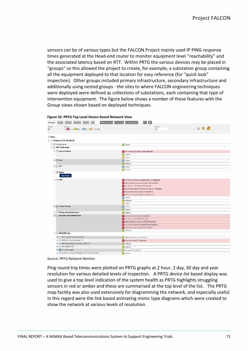
Project FALCON
FINAL REPORT – A WiMAX Based Telecommunications System to Support Engineering Trials 71
sensors can be of various types but the FALCON Project mainly used IP PING response times generated at the Head-end router to monitor equipment level “reachability” and the associated latency based on RTT. Within PRTG the various devices may be placed in “groups” so this allowed the project to create, for example, a substation group containing all the equipment deployed to that location for easy reference (for “quick look” inspection). Other groups included primary infrastructure, secondary infrastructure and additionally using nested groups - the sites to where FALCON engineering techniques were deployed were defined as collections of substations, each containing that type of intervention equipment. The figure below shows a number of these features with the Group views shown based on deployed techniques.
Figure 32: PRTG Top Level Device Based Network View
Source: PRTG Network Monitor
Ping round trip times were plotted on PRTG graphs at 2 hour, 2 day, 30 day and year resolution for various detailed levels of inspection. A PRTG device list based display was used to give a top level indication of the system health as PRTG highlights struggling sensors in red or amber and these are summarised at the top level of the list. The PRTG map facility was also used extensively for diagramming the network, and especially useful in this regard were the link based animating mimic type diagrams which were created to show the network at various levels of resolution.

Project FALCON
FINAL REPORT – A WiMAX Based Telecommunications System to Support Engineering Trials 72
The PRTG product is licenced by the number of sensors, FALCON initially purchased a 500 sensor licence which was just about sufficient to cover a minimum monitoring level for the system but the tool proved so useful and easy to use that this was extended to the PRTG 1000 licence allowing more flexibility. A further PRTG “map” facility was set up – this provided a graphical representation of the monitoring data. Maps can contain graphs as well as animating icons of various types (links, status blocks, user defined images etc) and allow for the aggregation of multiple sensors and devices to give a different cut (and therefore view) across the overall monitoring picture. Such “mimic diagrams” allow for a ready view for the control room with error conditions illustrated by red indications on link and status objects.
Some of the PRTG features could not be deployed (such as SMS text/email alert integration) as the WPD networking policy does not permit Internet connectivity.
5.2.3 Extended Monitoring Using SNMP For evaluation purposes a small number of sites were set up with SNMP enabled at the routers. A sample Primary site at Bradwell Abbey and a Secondary Substation site at Willen Rd Street Lighting were chosen. Additionally, SNMP on the Head-end router was also configured for this important network component.
The PRTG monitoring system is readily set up to connect with the SNMP traps on the enabled devices using a PRTG quick deployment facility based on templates. By this means the secondary substation routers could be tooled-up to provide various diagnostic data sets, including CPU, Memory and IO levels as well as providing other parameters supporting more detailed feedback such as chassis temperature. The following image is a PRTG plot based on the SNMP readout from the Cisco CGR 1240 router of its internal chassis temperature at Willen Rd (a pole mounted site) and covers a 48 hour interval around a hot summer day in June 2015 when the outside temperature reached around
22C. The diurnal temperature variation over the two day period is clearly visible:

Project FALCON
FINAL REPORT – A WiMAX Based Telecommunications System to Support Engineering Trials 73
Figure 33: Willen Road Substation, SNMP Temperature Monitoring
Source: PRTG Network Monitor
SNMP was not widely deployed however as this adds significantly to network load and for the FALCON network was considered largely irrelevant. It was deployed only as a test in readiness for diagnostic use if required.
5.3 Network Management The network was managed largely reactively using a monitoring approach based on operation of the combined tools described above. The Netspan REGISTERED sites and the converse NOT REGISTERED list were checked at regular intervals throughout the working day and cross compared to a display of PING response times for the same sites in PRTG. Using these combined radio and IP link views allowed better diagnosis of the position at any given time and experience with the performance of the various sites could be built up over time. Once poorly performing sites had been flagged, and in some cases understood to a first level, engineering staff could then be deployed to carry out site inspection. Where possible, remedial work would then follow, with this depending on the nature of the local circumstances (and listed elsewhere in this document). The management operation became largely a routine function and usually featured the same set of recurring rogue locations, with many “good” performing sites continuing to operate year-in year-out without issue.
5.4 Diagnostics Active monitoring allows for diagnosis of some forms of failure and after several months of closely watching the network it became possible to categorise some early failure

Project FALCON
FINAL REPORT – A WiMAX Based Telecommunications System to Support Engineering Trials 74
signatures within the monitored system parameters. This allowed a certain number of faults, many inherent to the pilot nature of the project, to be recognised and dealt with early once such familiarity had been gained. This included:
Recognition of a transient CGR router hang fault from a radio statistics signature. The RSSI UL/DL values would deteriorate and the UL RSSI would go to a particular value of -100dB and then the router would lose registration (on Netspan). Sometime later, all communications to the router would cease. Such routers were believed to be experiencing a WiMAX card firmware fault and simply needed a reboot (as workaround) until the problem could be rectified at source. Another automated workaround was also put in place in a test location to avoid the need to visit the site to reboot, with a watchdog deployed to auto-reboot the systems on detection of the issue in software rather than through monitoring;
The Airspan CPE units providing cross primary site connectivity (and at Winslow connectivity to the backhaul network via Horwood) were found to drop out occasionally at a number of Primary sites. This was easy to recognise as the Netspan system simply showed the CPE unit offline (no registration). All CPE equipped primaries dropped out at least once, but the Marlborough St, Childs Way and Bletchley CPEs were the most frequently lost. The dropouts were handled by a power cycle reboot of the units which were then restored to full function. There was no determined underlying cause. The Airspan CPEs received power using POE delivery with source power being local inverters within the primary communications racks. The set-up was not ideal and was suspected, though not proven, of being the root of the CPE dropout issues;
A number of sites exhibited on/off, discontinuous registration or long term instability in their connections in spite of having indications in the radio statistics of excellent signal strength and good Signal to Noise Ratios (SNR/CINR). After investigating the antenna bearing for such cases along with other environmental factors (situation, topology and cable integrity for example), the problems were often found to be the result of faulty WiMAX cards, although the same failure signature also resulted from co-channel interference (see section 6.4.2). A rapid rectification was usually possible by simply replacing the faulty cards. The main conclusion was not to discount any possibility when conducting investigations at problem sites;
Unexpected and usually long term signal deterioration diagnosed by signal trend monitoring over extended periods as was done regularly throughout the project. As mentioned elsewhere this resulted from a variety of causes including:
– Failing WiMAX cards (seen on a number of occasions);
– Foliage growing near the antennas (Leary Crescent, Newport Pagnell);
– Construction of buildings close to the substations or along the lines of sight (Unisys),
– Vandalism (deliberate rotation/movement of the antennas and in one case use of the antenna for target practice such as at Moor Park, Bletchley and Ashlands Stadium which was destroyed by fire);

Project FALCON
FINAL REPORT – A WiMAX Based Telecommunications System to Support Engineering Trials 75
– weathering of poorly made cable connectors or disconnection of cables (by means unknown).
IP level instability. During the early stages of the system level end-to-end integration the project saw a level of instability at the IP level that had not been suspected after observing the developing radio network over the preceding months as the rollout had progressed. This was (eventually) found to be a problem with a number of different possible causes (covered at length in this Report) and it illustrates the need to be mindful of the entire communications stack when considering the integration/test activities. To address this, the project looked for a way to detect these problem sites, eventually developing the diagnostic method described in Section 5.4.1 below;
Antenna misalignments. A significant number of cases were seen where there were good indications of signal strength based on monitored radio parameters but at the IP level there was instability (manifest as long ping response times and significant periods of no service). Such locations (Unit 32 Blundells Rd Bradville, Rickley Lane) had not received much attention given their seemingly acceptable radio parameters however when investigating the IP instability it was found that in these cases the antennas were significantly misaligned (as if they had been installed to a default spec square on to the building). Once the antenna was pointed to the base station the signal strength and noise ratio (CINR) were improved (in the quoted cases by over 10dB) and the IP level communications was improved significantly;
Excess traffic on some of the backhaul links – in particular the aggregated relay link to Newport Pagnell from Marlborough St results in the data from all the substations attached to the two primaries (Newport Pagnell and Marlborough St) being piled up on to the Marlborough St to Bradwell Abbey link.
As described in Section 5.2 on Monitoring of the Network, fault diagnosis and general system management is rendered much easier if the necessary diagnostic supporting information is available for analysis. Certain failure modes which result in the devices dropping off the network cannot clearly be managed remotely, but otherwise fault diagnosis is greatly facilitated by becoming familiar with the characteristics of the network operating in a nominal fashion.
For radio communication dead spots, site inspection is necessary to establish any immediate cause that could be present. Use of a portable pump-up mast allows for the investigation of different signal strengths at different heights from a possible list of candidate base stations which might be used to serve the location. Other diagnostic tools were also used on the FALCON Project including Google Earth, which can be preloaded with substation coordinates and details as well as the theoretical radio coverage map overlay (loadable from a KML file). Google Earth had multiple uses:
As a desk based planning and diagnostic tool. Using the line tool within the application it is possible to connect the substation to the local base stations, determine the range and bearing so that the bearing can be used either to set at deployment time (or check an existing) actual antenna bearing. The line on the map can also be converted to an elevation profile which readily shows the lie of the land

Project FALCON
FINAL REPORT – A WiMAX Based Telecommunications System to Support Engineering Trials 76
along the line of sight and thus illustrates clearly whether problems of this nature might be expected. Note that while this elevation profile does not include additional influencing factors such as foliage or buildings, it still provides a significant amount of input when assessing connectivity issues – some cases are clear cut while others remain ambiguous, but as a tool it does give that additional information;
As a field based tool to provide rollout engineers with a view of the local radio coverage as well as bearing information.
One aid to diagnosis for the FALCON communications network was the enablement of wireless capability on the CGR 1240 routers – allowing drive-by connectivity for engineers using diagnostic laptops with the Cisco management software suite (CGDM software) installed on them. This access is controlled from a security point of view using certificates and passwords. What this means is that engineers can visit the substation but don’t necessarily need to open them up (or more importantly climb a pole) to effect an investigation, download configurations etc. Thus investigation work is made simpler, safer and more rapid.
5.4.1 Quick-Look Diagnostic Mechanism The IP level instability referred to in the section above was manifested as an inability to execute some application level programs requiring sustained connectivity and was investigated by measuring unexpectedly long ping response times (RTT more than 300ms and often as much as 1500ms or completely timed-out). In many cases this effect was seen even at locations with seemingly very good radio stats.
With long term monitoring of the entire radio network being operated using the Netspan system from Airspan and the collection being made from this of full RF statistics for all locations at minute intervals, it was possible to develop a diagnostic tool for rooting out potentially problematic sites by inspecting the data. The project began by simplistically plotting at weekly intervals the key RF stats for each of the individual sites over a range of dates. This showed up some long term trends and allowed the project team to become familiar with the individual locations. This was however limited, and for good sites without any apparent issues had little advantage.
A significant step forward in early diagnostic capability was obtained when the approach was tried plotting CINR (signal quality) against RSSI (signal strength) based on long term average values for these two parameters. The averages were derived from monitoring results taken from radio signal statistics which had been gathered over several months and exported from the Netspan radio monitoring system. Two examples of the resulting plots for these parameters are shown below. In each plot, each data point on the graphs is the average CINR vs RSSI (Uplink in the first plot, Downlink in the second) at a given substation. It is readily seen that there is a very clear linear relationship between these values (though in the Downlink plot, the CINR limits at a value of around 31 and the plot consequently levels off). The relationship is not unexpected as the two parameters are closely correlated.

Project FALCON
FINAL REPORT – A WiMAX Based Telecommunications System to Support Engineering Trials 77
Figure 34: Plot of UL CINR against RSSI All Substations Figure 35: Plot of DL CINR against RSSI All Substations
Source: FALCON Project Source: FALCON Project
On closer inspection, it is possible to identify a number of points (substations) which do not fall on or close to the line. When these points were cross matched to the actual site name it was found that these were always problematic sites, some of which are mentioned elsewhere in this document. Care needed to be taken during this process as some sites had been adjusted in the interval in which the averages were taken, but this was managed readily when looking more closely at the “problem” list. The project therefore developed a largely automated and readily available method of checking site communications data link integrity using routine radio statistics data combined with a simple plotting function and then directing deeper investigation efforts at those sites not falling on the line (as illustrated in the figure below). This would be particularly useful during radio system rollout, though the method was developed too late for this to be used extensively on the FALCON project where our earlier investigations reinforced the concepts emerging from this approach. Had it not already been known which substations were experiencing significant connectivity issues, the conclusions would not have been so readily made.
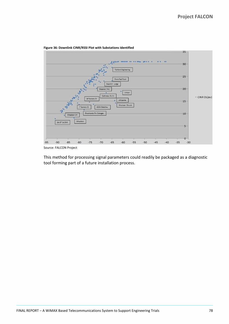
Project FALCON
FINAL REPORT – A WiMAX Based Telecommunications System to Support Engineering Trials 78
Figure 36: Downlink CINR/RSSI Plot with Substations Identified
Source: FALCON Project
This method for processing signal parameters could readily be packaged as a diagnostic tool forming part of a future installation process.

Project FALCON
FINAL REPORT – A WiMAX Based Telecommunications System to Support Engineering Trials 79
SECTION 6
6 Maintenance & Remedial Work
Project FALCON
FINAL REPORT – A WiMAX Based Telecommunications System to Support Engineering Trials 80
Once the FALCON telecommunications system was in a nominal operating mode, the emphasis of the telecommunications workstream shifted to routine maintenance essentially to manage the service and ensure continuity in the flow of data back to the Head-end for analysis.
6.1 Tolerance of Network Problems It was found that continuous, completely reliable network operations were not always necessary at all locations on the network. There is some ability to tolerate network outages and/or variations in radio reception conditions. This depends very much on the nature of the connected site and what functions are being supported there by the communications network.
Typically, simple equipment monitoring will not always require continuous communications to the Head-end, where the data is ultimately collected/assembled for analysis, as it is often buffered at the substation where it is being generated and will be released by the monitoring device (such as the Gridkey LVM monitoring units) once connectivity is re-established in a store and forward fashion. In such cases where any breaks in communications are short compared to the buffering and recovery capability of the data gathering components – there are no overall resulting data gaps at the Head-end once any “fill-in” data elements have been integrated back into the overall dataset. On the FALCON Project, where there was no explicit need for real time display of monitored data, it was therefore not necessary to expend significant effort on fine tuning the radio connectivity at such sites. The situation is very different for instances where real-time control or display is required. Nevertheless all possible effort should still be put into making each site communicate in the best manner since poorly connected sites can stress the overall network and result in operational degradation.
6.2 Handling Problem Sites On a pilot trial project there is some possibility of a flexible / adaptive approach which allows for certain problem cases to simply be omitted from the programme of work. A rollout for BAU does not however permit such a luxury. On the FALCON Project we did abandon a small number of unworkable locations whose function was not involved in the formal trials where the only equipment was therefore Low Voltage Monitoring (LVM). At these locations the decision to abandon was easier in the case where other sites of the same customer category were already connected successfully and the LVM equipment was simply reallocated to a new location of the same category.
For a complete investigation however, and recognising that a real-world rollout is always going to throw-up problematic locations, FALCON also explored some alternative and where possible complementary telecommunications solutions to the use of WiMAX.
While some 65% of sites eventually came on-stream in a stable, usable fashion, a difficult to resolve core of sites needed additional attention which in the end comprised mainly of remedial works on antenna mountings – either to raise these physically higher or pan them in better to the correct bearing with respect to the base station. As noted

Project FALCON
FINAL REPORT – A WiMAX Based Telecommunications System to Support Engineering Trials 81
elsewhere, these problems were at least partly explained by the pilot nature of the project and constraints applied during the system design and early rollout phase, particularly in respect of the primary infrastructure, and a more complete base station deployment would have helped in this respect. Given these problems, and the directive for the project to fully investigate issues that arose, the project therefore considered what further options were open to it should a more radical approach to difficult connectivity be required for some of the locations. The options considered, as detailed in Ref x, were:
Power Line Carrier (PLC)/Broadband over Powerline (BPL);
RF Mesh (a promising option but one not possible at the current time due to regulatory restrictions and lack of available hardware modules operating on acceptable power levels and frequencies);
Microwave;
Wifi 802.11;
GPRS/3G/4G;
DSL;
Direct Ethernet.
WiMAX and Scanning radio were omitted from the analysis carried out by the Project as these were already ongoing project implementation activities.
After consideration of the above and discounting of the unlikely solutions, the following options were chosen for further investigation (or as per the first item, were already ongoing on FALCON):
A scanning radio implementation;
RF Mesh for a fully complementary solution;
A WiFi solution for substations in close proximity to each other;
A DSL solution.
All were feasible technically but there was insufficient time and resources to actually deploy any other, than the first. A future project may consider these possibilities.
6.3 Lines of Sight and Coverage A WiMAX implementation covering all sites in a given area would require a more rigorous analysis of the radio coverage and potentially many more base stations would be needed to give complete blanket coverage at all possible locations8. On FALCON an approach was taken with the base station setups, as has already been described elsewhere in this
8
Precisely how much more rigorous: how many more base stations and how this affects the costs and therefore the viability of WiMAX would be an interesting investigation to carry out but not one which was done on FALCON.

Project FALCON
FINAL REPORT – A WiMAX Based Telecommunications System to Support Engineering Trials 82
report, which used the following approach, which would necessarily apply for a full BAU rollout:
1. Only WPD owned facilities were used for the base station deployments. This meant that in Milton Keynes 9 primary substations were chosen across the trials area and fitted out for the support of base stations;
2. No third party dependency was introduced for base station equipment deployments;
3. Wood poles having a 15m maximum height (when extended by metal mounting brackets at the top of the poles) were installed for the purpose of mounting the base stations / antennas. Under 15m allowed this to be done within “permitted development” rights, so avoiding the need to obtain specific planning permission;
4. Because of the limited budget for the trials, not all available primary substations in the trials area were utilised and not all those that were have been fitted out with multiple transceivers/antennas.
The consequence of this approach was that it limited the coverage to a certain degree for the prototype trials network. In addition, there will always be some locations where radio coverage is difficult and this happens for a variety of reasons. Some of the issues that affected FALCON site connectivity are listed below and are further followed up or developed elsewhere in this document:
1. Substations tend to be hidden out of the way, by design in many cases, so as to be unobtrusive and not drawing attention to themselves. This can therefore mean that they are deliberately placed where the conditions necessary for good radio communications are not always facilitated;
2. Substations may be in the lea of, or surrounded in their immediate environment, by buildings. It is not unusual for a substation (which is a small single story building or even just a palisade housing) to be located on a housing estate surrounded by much taller houses or garages or other blocks. The issues may be worse on industrial parks where the buildings may be larger and/or more substantial. This may or may not be a problem depending on lines of sight to the closest base stations. The actual situation varies a lot from place to place depending on the size and proximity of the surrounding buildings, the lay of the land and other factors such as trees/bushes. Furthermore there may be other more distant and therefore less obvious buildings along the line of sight to the base station especially if there is high land along the line of sight. Close buildings do however provide an opportunity to catch a radio reflection, thereby yielding an otherwise unexpected capability to connect via a different base station in situations where the connection to the proposed one is not possible. Instances of new construction were also seen to have an adverse effect – notably at Unisys Logistics Centre at Fox Milne, an active trials location, where a three story warehouse type building was constructed very close to the substation and in the line of sight of this location to the primary base station at Fox Milne primary. As seen in the signal strength graph below (UL / DL RSSI), the deterioration was rapid at the point where the side cladding was added to the initially erected steel frame.

Project FALCON
FINAL REPORT – A WiMAX Based Telecommunications System to Support Engineering Trials 83
Figure 37: Long Term Signal Deterioration at Unisys Logistics Centre
Source: Netspan Monitoring System Long term Stats
3. As with buildings, trees and bushes can be problematic. There is some possibility for trimming of trees and other foliage on the immediate land if this is owned by the DNO but otherwise lines of sight are best set to avoid such obstacles. Trees in leaf can be particularly problematic for radio reception in general, however this was not too much of a widespread issue for FALCON where little global improvement in radio signal strengths and signal to noise ratios was seen in the autumn when the leaves fell and conversely little degradation appeared to take place in spring/summer as the leaves reappeared except in locations where the foliage was thick and in the immediate vicinity of the antenna, as was the case at a handful of sites. By way of a specific example, Malins Gate Substation ping response times are shown in Figure 38 below. Malins Gate is situated in a dip and surrounded by high trees of various types. This substation will always pose a problem for communications when these trees are in leaf. Through the winter from October to May the ping times are very good at just over 100mS. Through the Summer period, however, the ping times regularly extend to in excess of 600mS and often exceed 1s or even result in complete loss of traffic. Fortunately the LVM device at this location was tolerant to network connectivity interruptions and all the data was retrieved as the unit caught up during periods of connectivity.

Project FALCON
FINAL REPORT – A WiMAX Based Telecommunications System to Support Engineering Trials 84
Figure 38: PRTG Ping RTT Times at Malins Gate (Annual Plot)
Source: PRTG Network Monitor
4. Topology of the land is a major issue, as radio propagation is clearly affected by this key environmental consideration. Even the Milton Keynes trial area, which at first appearance is relatively flat, does in fact have several gentle though extended rises and falls in the land surface. The worst effects were seen from short distance hills shading the substation from its main base station, such as that prevailing at Chadds Lane Energy Storage site. These features most likely escaped the initial radio analysis. The expected base station for Chadds Lane (Secklow Gate) was behind a steep hill that rose away from the substation for around 50 metres with a rise of around 20m at the top of which, on the brow of the hill, were houses and trees. To obtain any connectivity at Chadds Lane it therefore proved necessary to point the antenna towards the much more distant and less optimally aligned Fox Milne Primary base station. Connectivity should have been very difficult from Chadds Lane via Fox Milne due to its distance, the fact that Chadds Lane is well outside the main beams of the 2 transponders at Fox Milne (107 and 128 degrees off those beams which have a width of around 60 degrees), and housing along the line of sight. However a usable signal was achieved by raising the antenna to around 7m above the ground. The fact that this site connected to Fox Milne at all was surprising and must have been through a fortuitous side lobe of the base station.
5. Transient issues such as the weather and moving/parked vehicles. Rain attenuation can cause signal degradation and even loss and rain can also affect radio reception long after it has ended where it results in wet foliage along the main line of sight.
Given the above apparently perilous situation in regards to prospects for good radio connectivity, there are however seemingly hopeless situations where FALCON found that good radio reception can nevertheless be obtained following careful investigation and
Project FALCON
FINAL REPORT – A WiMAX Based Telecommunications System to Support Engineering Trials 85
once appropriate remedial action has been taken. Understanding the nature of the problem is key.
6.4 Interference and Restrictions The FALCON Project found a number of reasons for poor radio connectivity at substations and in addition to poor signal strength, one of the more obscure reasons for problems was found to be radio interference between different FALCON sites. The project also noted the possibility of interference caused by our WiMAX transmissions affecting other systems and potentially rendering them inoperable (and/or vice versa) and investigated one candidate case of this that had been reported to us.
6.4.1 Radio Signal Strength Radio signal strength is crucial for reliable communications. However it was found that a close look needs to be taken at the whole range of available radio network indicator parameters when assessing the network health (a holistic view). A good signal strength does not necessarily mean that the signal to noise ratio will be good and/or that at the IP level, the communications will proceed unhindered. One major factor that was found to be implicated in cases of poor IP level communications in spite of good RSSI levels is the correct bearing of the antenna – specifically how far off the true bearing of the base station is the antenna alignment. Following the discovery of this effect it became possible to diagnose sites with suspected poor antenna alignment from the IP ping plots – those with lots of packet loss but where signal levels were good. This was found to be the result of antenna pointing inaccuracies. Examples included:
The Linx, Bletchley. A very clear case where on inspection the antenna was found to
be pointing 180 off the bearing of the Bletchley base station to which it was attached. This meant that this site was connecting using the back of the antenna – a possible condition but one which Airspan indicated would give a theoretical 20dB lower signal level than the antenna being correctly aligned. Immediately following realignment, the signal level improved by around 20dB from -84dB (CINR 23) to -64dB (CINR 36) and the dropped packet levels went effectively to zero9. Significantly, at a level of -84dB pre-adjustment this signal level had clearly been expected to be usable, and the site had not attracted much attention. Nevertheless, ping results for this and other similar sites showed significant instability at the IP level – with long ping times (in excess of 500 ms) as opposed to an expected 120 ms, numerous timeouts and packet drops and communication was only established reliably once the bearing had been corrected.
The figure below illustrates the above narrative and in common with other plots used in this report also illustrates the value of using PRTG for verifying the status of the IP level communications.
9
When looking at metrics such as dropped packet levels using monitoring facilities, there are multiple potential causes of these losses (not all of which are local to the monitored entity) and therefore stating that all drops have been eliminated as a result of action taken is not an assessment that is readily made.

Project FALCON
FINAL REPORT – A WiMAX Based Telecommunications System to Support Engineering Trials 86
Figure 39: PRTG Ping Response Times at The Linx, Bletchley
Source: PRTG Network Monitor
Unit 32 Blundells, Bradville. This site was found to be aligned on a bearing of 143
but connected to Bradwell Abbey which has a true bearing of 239 from the site. The antenna was therefore panned-in and the DL RSSI subsequently increased from -89dB to -69dB and again the dropped packet levels went effectively to zero in spite of there being trees on the new line of sight;
At Newport Pagnell Local, which is immediately next door to the Newport Pagnell primary substation, signal levels were exceedingly high (around -20dB level). In order to reduce this, the antenna at the substation was initially de-pointed (directly away from the base station). This caused noisy unstable communications which proved problematic for an interval. A much better result was obtained by correctly pointing the antenna but attenuating the signal level to around the -50dB level using in-line attenuators (a rapidly fitted and reasonably cheap solution). Attenuation proved to be a useful ability at several sites with excessively high signal strength. Various attenuation levels are available for installation and these can be connected in series to provide a wider range of options.
6.4.2 Inter-site Radio Interference The various FALCON substation sites operate on three frequencies which are themselves reused across the trials area. Any given site chooses a single frequency from the master scan list to find the best signal in its area. The frequencies available are: 1432.5 MHz, 1437.5 MHz and 1442.5 MHz. The initial radio setup organised the various base station units (two at most primaries, three at Horwood, one at Bradwell Abbey and Childs Way)

Project FALCON
FINAL REPORT – A WiMAX Based Telecommunications System to Support Engineering Trials 87
to operate on a frequency plan which attempted to minimise the risk of co-channel interference by geographical separation. However this proved difficult to eliminate in a small number of cases given the limited choice available.
The main interference issue was found to be the result of unfortunate orientations in alignments where a particular substation could see more than one primary transmitter operating on the same frequency. This effect was not initially apparent when a substation was being commissioned as at this early stage in the project the IP level quality of each site was not being investigated at set-up, the main diagnostic at this stage being a simple view of RSSI.
Examples of sites later found to be experiencing inter-site radio interference included:
Moulsoe Church;
Thorneycroft Lane, Downhead Park;
Church End Lathbury;
Whaddon Council Houses;
Brooklands Farm Cottages, Broughton.
Moulsoe Church, 14.9KM distant from Little Horwood base station, has a clear downhill line of sight across the open basin (in which sits Milton Keynes) and readily connected to Horwood with a -82dBM signal strength, which was maintained as a good connection, throughout the Silverstone 3.5GHz radio silence. Normally on Fox Milne base station, only 2km distant, Moulsoe had a very poor connectivity record and was often not connected in spite of having a seemingly good signal to Fox Milne measured simplistically in terms of radio parameters. Inspection of the base station registration history plots revealed that the site was actually hopping between base stations, as illustrated in the Netspan registration history below, which also illustrates the extended intervals with no registration:
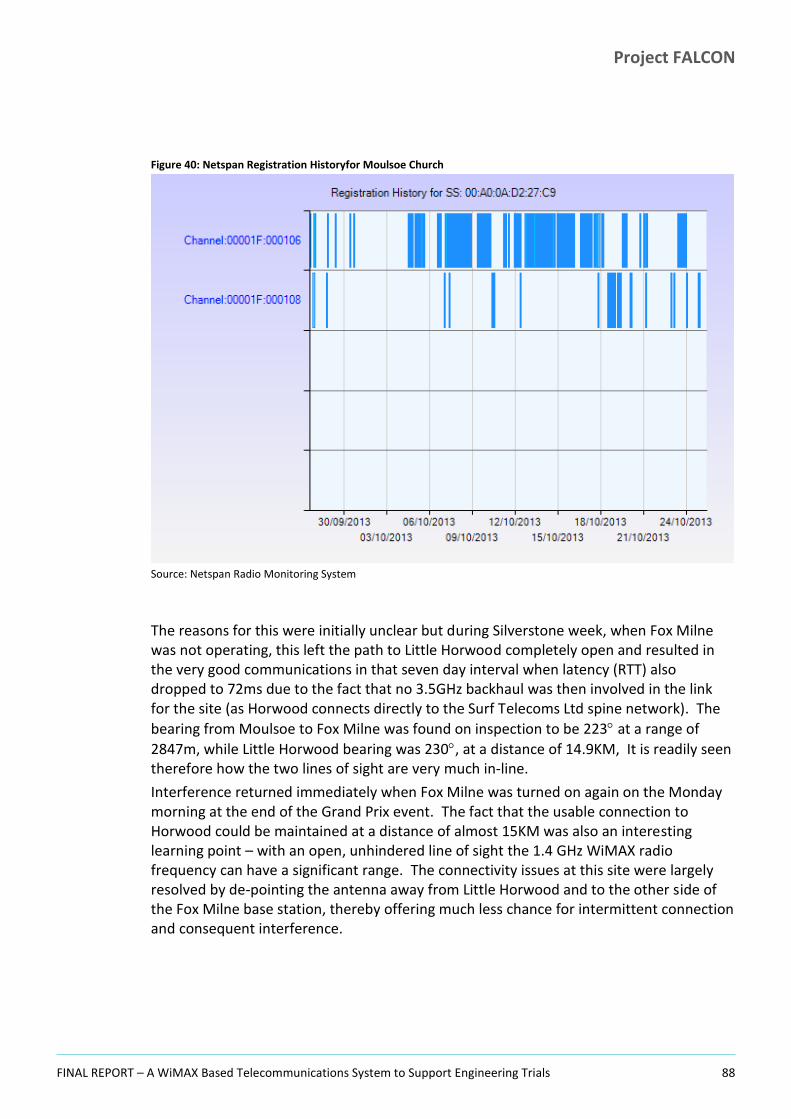
Project FALCON
FINAL REPORT – A WiMAX Based Telecommunications System to Support Engineering Trials 88
Figure 40: Netspan Registration Historyfor Moulsoe Church
Source: Netspan Radio Monitoring System
The reasons for this were initially unclear but during Silverstone week, when Fox Milne was not operating, this left the path to Little Horwood completely open and resulted in the very good communications in that seven day interval when latency (RTT) also dropped to 72ms due to the fact that no 3.5GHz backhaul was then involved in the link for the site (as Horwood connects directly to the Surf Telecoms Ltd spine network). The
bearing from Moulsoe to Fox Milne was found on inspection to be 223 at a range of
2847m, while Little Horwood bearing was 230, at a distance of 14.9KM, It is readily seen therefore how the two lines of sight are very much in-line.
Interference returned immediately when Fox Milne was turned on again on the Monday morning at the end of the Grand Prix event. The fact that the usable connection to Horwood could be maintained at a distance of almost 15KM was also an interesting learning point – with an open, unhindered line of sight the 1.4 GHz WiMAX radio frequency can have a significant range. The connectivity issues at this site were largely resolved by de-pointing the antenna away from Little Horwood and to the other side of the Fox Milne base station, thereby offering much less chance for intermittent connection and consequent interference.

Project FALCON
FINAL REPORT – A WiMAX Based Telecommunications System to Support Engineering Trials 89
Figure 41: Moulsoe Church Ping RTT Times Before and During Silverstone Week
Source: PRTG Network Monitor
A similar effect to Moulsoe Church was seen at Broughton Village substation where the performance was improved during nominal operations by adjusting the antenna direction to fix this so as to be on the other side of the bearing to Fox Milne from Little Horwood. Broughton Village substation antenna was unfortunately looking directly at Little Horwood (in fact on the exact bearing of the very distant station).
At Thorneycroft Lane, the site was panned in on the Marlborough St Primary WiMAX communications node but in spite of a seemingly very acceptable signal strength of around -54dB10 was found to be consistently poor in terms of IP connectivity - with extended drop out intervals and long but also highly variable ping round trip times as measured by the monitoring system PRTG. When the bearings to the local base stations were investigated, these were found to be:
Marlborough St: primary 293.92 at a range of 1.71km;
Fox Milne primary: 113.93 at a range of 2.17km;
Newport Pagnell primary 17.22 at a range of 2.3km but unworkabledue to buiildings and topology.
10
It is thought that this signal strength is the sum of both interfering signals and is thus not a good reflection of the quality of the signal in such cases - being effectively a false high. Attenuation acts on both signals but depresses the weaker interferer more and therefore suppresses its effect.

Project FALCON
FINAL REPORT – A WiMAX Based Telecommunications System to Support Engineering Trials 90
It was noticed that Fox Milne and Marlborough St are 180 apart from this site (to within 1/100 of a degree!). So with a similar range and clear line of sight topologically to both primary substations (broken only by houses in the very short distance) this looked again like pickup on the back of the antenna (from Fox Milne) interfering with the front (Marlborough St) an effect already seen at the Linx, Bletchley. Turning the antenna onto Fox Milne might have been an option but was judged unlikely to help as the interference would just be the other way round.
It was therefore decided to install attenuation to see if that made any difference, this was done on in October 2014 and made an immediate and huge difference.
The plot below shows very clearly the PRTG ping times over a thirty day interval towards the end of which the resolution was obtained. Red lines (unwanted) are timeouts, the blue filled line shows acceptable periods of connectivity.
Figure 42: Thorneycroft Lane Ping RTT Before & After Attenuation
Source: PRTG Ping Monitor
6.4.3 Interference with Other Systems In October 2014 the project was contacted via WPD by a factory location in Milton Keynes. The Facilities Manager had observed that radio control for the site barrier entry system had stopped working and looking back to when this occurred, concluded that it was seemingly coincident with the installation of the FALCON antenna located on the substation just outside their gates. Other means of barrier operation (manual and keyfob proximity operation) were still working correctly and a complete overhaul of the system

Project FALCON
FINAL REPORT – A WiMAX Based Telecommunications System to Support Engineering Trials 91
by the barrier supplier had found no problem. The project contacted the supplier for radio system details and to arrange a series of tests.
The entry system was based on a 2.4GHz radio system which could be operated from vehicles approaching the factory access barrier. Clearly the FALCON WiMAX operating frequency of 1.4GHz is not on the face of it in the same band, though with very close proximity (5-6m) and the possibility of harmonics at that range we considered that there was some potential for issues arising. However as 2.4 GHz is an unlicenced frequency band it can be used in any local factory unit and even welding is a possible source of high frequency interference where inverters are being used increasingly to provide hi-frequency soft start arcs. Thus we considered that there were possibilities that the factory were producing their own interference without realising it, or else it was some other source of 2.4GHz band emissions or some other issue. Meanwhile, the FALCON WiMAX radio operated on a licenced frequency issued by Ofcom, and no one other than WPD/FALCON and the MoD should have been using the three frequencies of: 1432.5 MHz, 1437.5 MHz and 1442.5 MHz.
The other frequency used for automation by the project (Scanning Radio) was not operational at the time of the detection of the interference. This frequency is within the un-licenced band between 458.5 and 458.9 MHz. These frequencies can suffer interference from traffic signalling systems so there is potential in such cases for transient problems to occur but this was certainly not applicable at the site in question.
Following investigation of the matter on-site in October 2014, it was finally determined that neither WiMAX nor WiFi were the cause of the barrier problems which were found eventually to be caused by incompatible remote handset units. The value to the project of this was the investigation and follow up which ultimately yielded a (good) negative result.
6.5 Transient Issues The project experienced a number of transient issues (aside from radio interference and growth of foliage and leaves on trees discussed above) which also affected the radio communications to some degree. These issues can in general be anticipated for a line of sight communications system, but it is worth listing those that were seen.
Weather conditions. Rain attenuation causes signal degradation and even loss. Rain can also affect radio reception long after it has ended where it results in wet foliage along the main line of sight. This effect was seen on occasions but was not extensively investigated;
Moving/parked vehicles. Not only can vehicles move in front of an antenna which is mounted too low causing a short term loss, the project also experienced several instances of high sided vehicles parking for extended periods in front of low antennas while they unloaded or parked up (at light industrial locations – e.g. at Tanners Drive and Michigan Drive substations) and even one case of a lorry bodily moving an
Project FALCON
FINAL REPORT – A WiMAX Based Telecommunications System to Support Engineering Trials 92
antenna where some object such as a wing mirror contacted and rotated it (Oxford St. Bletchley). In such cases the signal loss was for an extended period (and effectively permanent until the antenna was readjusted at Oxford Street);
Building works in the line of sight. Construction of buildings can attenuate previously good signal or perhaps introduce radio reflections which act to reduce signal strength and/or quality;
Unknown source signal degradation. At various times some sites would simply exhibit an unstable signal profile either in the RF or sometimes without apparent RF issues just in the IP communications layer. Without any apparent reason a site might then experience packet drops or poor network behaviour usually lasting a short period, though at some sites might extend over several days. Such cases may be attributable to atmospheric conditions or a collection of prevailing circumstances which acting together might just take a borderline location close to an operating limit and render it unstable for the periods observed before the site then recovered at some later point.
This sort of event is very difficult to track and resolve because by the time the issues have been noted in many cases, the problem is shortly thereafter resolved on its own. Airspan have also suggested that morning and evening effects are seen in some situations on radio networks, but additional reasons for unknown effects of this nature could investigated, and might include:
– Highly localised rain attenuation at a site sufficiently remote from the control centre to not be noted there as a possible cause. Such events might be readily checked out under a future pro-active investigative programme of work;
– Wind moving an antenna in an oscillatory fashion. This was a clear possibility in some substations with extended, unbraced mounting poles;
– “Atmospherics” – inversion layers, fog;
– Localised intermittent radio interference (e.g. high power transmitter breaking through at or near the WiMAX frequency). The project was not expecting any direct legal WiMAX interference on the 1.4 or 3.5GHz frequencies as WPD has the only usage dispensation in the area (excepting during the Silverstone event in July each year);
– Any of the transient issues noted above;
– Poor signal connections coming and going (cabling issues, water ingress);
– Wider instantaneous or more extended network load resulting in increased localised stress levels and IP packet loss or extended timeouts;
– IP address clashes (not expected once rollout and integration/checkout completed) but certainly a problem seen at least twice during the FALCON installation process;
– Events such as the unresolved Finch Close router problem perhaps caused by some curious interaction of router and base station (see below).

Project FALCON
FINAL REPORT – A WiMAX Based Telecommunications System to Support Engineering Trials 93
6.6 Unresolved Issues During ongoing system operations in February 2015 an unusual problem emerged at the Finch Close secondary substation. This site had been in operation for many months without issue but suddenly, following the site recovering overnight from a hang state, started generating significant amounts of noise data on the network which detrimentally affected several other substations mainly connected to the same primary (WiMAX nodes 1 & 2 at Fox Milne Primary site). The worst affected sites were:
Pearmain Close
Stamford Avenue Springfield
Falcon Avenue (battery technique location)
But also Butterfield Close Woolstone (on Secklow Gate primary) also appeared to be affected. With Finch Close active on the network the listed sites (and Finch Close itself) all suffered intermittent IP level comms and lost connectivity (registration). Inspection of the data throughout at the locations showed large amounts of data being passed (in excess of 1MBPS).
The project embarked on a series of investigations to try to pinpoint and resolve the cause. Initially the WiMAX card in the CGR router at Finch Close was swapped out for a different unit but the problem persisted. The issue went away when the site was off (power down state). The router chassis was also then swapped without effect – i.e. a new router with a different WiMAX card at the location gave the same result. The LVM unit was also disconnected but the noise continued. An interval with no noise was observed (ironically while Cisco were at Horwood aggregation site waiting to do some diagnostic packet captures) but this appeared to be while the LVM unit was catching up buffered data after the router was turned on after a 12 day off interval. However the noise did resume after 3 hours and continued even after the LVM unit (the only attached equipment) was disconnected. This aspect has never been understood.
As a next step, the router from Finch Close was recovered to the FALCON lab where it was set up via the local lab connection onto the Bradwell Abbey primary. It was hoped that it would be possible to localise the issue and perform an in depth investigation. However this same router (already a itself a replacement) which gave the noise at the Finch Close site ran perfectly in the lab, even with an LVM load. On returning the unit to Finch Close the issue reappeared.
A final test was done in which the scanning list on the CGR router was set to use the frequency of Fox Milne WiMAX Node 2 (the other WiMAX node at the Finch Close local primary). Upon connection the site came up and worked perfectly well, without noise or disruption to the other sites noted above. This is the state in which the site has been left operating.
Clearly some form of unfavourable interaction between any deployed router at Finch Close and Fox Milne node 1 must have taken place. We are still unable to account for the behaviour as it was clearly not a CGR hardware issue (as it affected multiple units) and

Project FALCON
FINAL REPORT – A WiMAX Based Telecommunications System to Support Engineering Trials 94
other sites on Fox Milne Node 1 worked correctly (so it was not a simple issue on the base station side). We saw no evidence of local issues (such as new buildings or any of the sort of transitory issues noted elsewhere in this document) and a full investigation might have required a radio interference inspection to be carried out. Once the issue was worked around successfully however the Project needed to concentrate on other priorities (the Finch Close investigation had already taken several days of effort).
Project FALCON
FINAL REPORT – A WiMAX Based Telecommunications System to Support Engineering Trials 95
SECTION 7
7 Network Security

Project FALCON
FINAL REPORT – A WiMAX Based Telecommunications System to Support Engineering Trials 96
This section discusses the project approach to protecting and securing the WPD network assets, devices and upper layer protocols (such as IEC61850, DNP3, SNTP, Radius etc.) that are considered “critical infrastructure” in the FALCON trial network, from both intentional (malicious) and non-intentional cyber attacks. It gives an insight into the reasoning which influenced the FALCON network security architecture. Additional detail is available in the published FALCON White Paper on Security authored by Cisco for the project.
The FALCON Field Area Network (FAN) and Wide Area Network (WAN) backhaul communications infrastructure is based on standard 802.16 (WiMAX) covering the physical and data link layer. There are security specific dependencies and implications to this technology, much as would have been the case with alternative technologies such as MPLS-VPN. Should the WiMAX infrastructure be compromised in one form or another, the upper layer protocols and traffic flows will be affected just as much. Most likely, this would result in a denial of service problem and that is essentially the equivalent of “unavailability” of critical services equating to a red alert condition. To address that concern, vendors and system integrators working on adjacent or overlapping FALCON domains of technology act in a coordinated fashion and work off a single security blueprint to maintain consistency of security across the entire infrastructure.
Key security areas for WiMAX implementation for FALCON were the following:
Authentication; is based on EAP-TLS using X.509 certificates – this is the preferred way to secure against Man-in-the-Middle attacks;
Encryption; Based on AES 128-256 bit encryption, providing strong support for confidentiality of data traffic;
Availability; WiMAX deployments will use licensed RF spectrum, giving them some measure of protection from unintentional interference.
This is supplemented by usual due diligence business processes, which in this case includes penetration testing.
The diagram below shows a relevant representation of a network security design framework. Functional mitigation techniques are listed per OSI (Open Systems Interconnection) layer while the non-functional (policies) are listed across all OSI layers on the right hand side.

Project FALCON
FINAL REPORT – A WiMAX Based Telecommunications System to Support Engineering Trials 97
Figure 43: Network Security Design
These techniques were implemented in a phased approach on FALCON. Some mitigation techniques are cross functional or cross OSI layer and are explained below in greater detail where the main elements of the security solution are presented.
7.1 Approach The substation configurations of primary and secondary entities are based on blueprints that are as consistent and flexible as required to fulfil current and future needs. The former is needed to ascertain feasibility of maintaining configurations across hundreds if not thousands of assets and devices, while the latter is needed to make sure that change management can be applied as seamlessly as possible during the lifecycle of all relevant equipment and systems.
7.2 Physical Security of Critical Infrastructure There was no explicit element of physical security work done as part of the FALCON Project which effectively relied on the existing physical security controls in place at the sub stations involved in the project. However, for future use, it is interesting to address some of the dependencies between physical and electronic perimeter security. Best practice is to align both domains in such a way that all relevant threat levels are addressed in a holistic manner, covering both the physical and the electronic perimeter. It is easy to understand that at locations where potential intruders can gain relatively easy access to substation equipment, further security at infrastructure level is needed.
The substation architecture for FALCON adopted by WPD was capable of supporting future physical access control by offering extensibility to a multi service bus. This offers the capability potential to securely connect IP cameras, badge readers, VoIP (Voice Over IP) and related equipment if such is needed in future. Backend systems for management of security and surveillance equipment can be located in a separate zone in the Head-end

Project FALCON
FINAL REPORT – A WiMAX Based Telecommunications System to Support Engineering Trials 98
DMZ or securely routed to an existing data centre. A future review of the current control centre design, covering for example QoS, may be required but in principal there are no technical constraints to implement a multiservice bus in larger or less physical secure primary substations at a later stage. Benefits may be found in multiple areas ranging from thermal cameras monitoring the switchyard to automated access control covering staff or contractors on premise through badge or biometrics reader, VoIP and video.
7.3 Implications for Performance and Latency Some critical traffic flows like teleprotection, centralized remedial action schemes and related real-time controls are very sensitive to delay and jitter, imposed by deep packet inspection, intrusion detection or other interception techniques that contribute significantly to serialisation delay of packets. It is important to understand these potential constraints early in the design phase of the control centre and substation network blueprints, by making sure that a class of low latency traffic can be securely accommodated. It is hard to generalize critical latency and performance requirements for all power distribution or power transmission environments, however there is some rationale involved and previous experience that indicates that such low latency flows are best protected by ACL based packet filters that operate at wire rate. ACLs are implemented in the routers forwarding hardware and do not compromise the performance of high performance applications.
7.4 Secure Network Segregation Where applicable and technically feasible, the network infrastructure of process control systems is divided into multiple zones with different functions and protection requirements. In particular, different technical and operational domains should be segregated from one another. In the FALCON design this recommendation was applied at substation and at the Head-end level. This enforces traffic flows belonging to different functional groups to be segmented by way of respectively Virtual LANs (VLANs), Access Control Lists (ACL’s) and Deep Packet Inspection based firewalling. These measures mitigate attacks originating from compromised network segments to adjacent zones and helps to withstand a cyber attack by isolating the offensive traffic or as a minimum, slowing down the offending patterns, offering WPD or partner security staff enough time to intervene and apply corrective action.
7.5 Device Hardening It is best practice to consider telecommunications equipment as critical cyber assets that are constantly under threat. Neglecting to adopt this attitude offers attackers some leverage to get in through unexpected entry points. A number of measures have been agreed upon and integrated in the FALCON Project network design to mitigate the risk of telecom equipment being compromised. The most notable measures are listed below:
Unnecessary services are disabled;
Banners on terminal access to all relevant devices and nodes advise users with an appropriate legal warning that they have connected to a secured infrastructure;

Project FALCON
FINAL REPORT – A WiMAX Based Telecommunications System to Support Engineering Trials 99
Secret passwords are encrypted in the configuration file using MD5 (Message Digest 5) hashing so as to be unreadable;
A low console port timeout interval (five minutes) is enabled on all serial console and virtual terminal ports to disconnect any inactive sessions;
The service “tcp-keepalives” is configured to disconnect and clear idle sessions running over TCP, hence avoiding exposure by open TCP sessions to a critical network device;
All unused physical ports are kept in the persistent shutdown state to preventunauthorized physical access to the network and must be actively enabled before use;
CDP (Cisco Discovery Protocol) is disabled. While offering useful services during troubleshooting it also offers an undesirable backdoor to reconnaissance efforts that could be exploited by malevolent or unauthorized users.
These device hardening measures have been implemented across the board in both the control centre and in substations.
7.6 Management Plane Protection It was agreed that on all routers and switches, access to the terminal lines would be protected via an ACL applied to the virtual console ports (lines). The ACL only permits connectivity from trusted hosts located on the management network segments within the control centre.
Management access to the network nodes will be further protected through the use of secured application layer protocols. Only secure shell session (SSH) support will be made available for terminal access of the network devices and secure web access (HTTPS) for GUI applications. This measure covers two concerns, it mitigates unauthorized access to the command line interface (CLI) via an unsecure protocol (Telnet exchanges credentials in clear text) and secondly it blocks potential exploits of the CPU like denial of service (DoS) and distributed denial of Service (DDOS) attacks via the virtual console ports.
7.7 Control Plane Protection Telecommunications equipment is roughly comprised of two logical key components, the control plane has knowledge on where to send packets to, inferred from simple or complex routing and switching algorithms and the forwarding plane which handles the actual forwarding of packets in the most efficient and secured way possible.
The likelihood of an attack staged via the forwarding path inside any of the substations is negligible due to existing access control applied at the perimeter like packet filters or access lists. As such, Control Plane Protection makes most sense at the Head-end routers where lots of control data gets aggregated from sources that may not all be under a strict span of control at day one.
Control Plane Protection avoids the CPU of the network device becoming overwhelmed by undesirable levels of “control” traffic. Such traffic is under normal circumstances light to moderate and the CPU can handle the requests without much effort. Some denial of

Project FALCON
FINAL REPORT – A WiMAX Based Telecommunications System to Support Engineering Trials 100
service attacks do target the control plane deliberately but system defects or caveats could yield the same behaviour, causing the device under attack to drop a mix of legitimate and undesirable traffic without being able to make a distinction. Applying Control Plane Protection mitigates this risk significantly but requires careful testing and monitoring to avoid unstable Control Plane behaviour.
7.8 Security Governance A governance model must be developed or adapted such that ICS and SCADA environments subject to Ethernet and IP migration are covered in terms of adequate procedures, policies and standards. There are many ways to interpret security governance models but most of all it is necessary to ascertain quality assurance and consistency of the desired security mitigation strategy. As mentioned earlier in this document, there is no single source of truth in terms of which governance model to embrace, but many customers already have an ISO 27002 or in the US a NIST 800-50 based structure in place. These should be complemented with ICS specific publications such as IEC 62443 and ISA99.
More specific details on how these security measures were implemented in FALCON can be found in the next section.
7.9 Substation LAN Security Design A distinction is made between primary and secondary substations in regard to LAN security. Existing physical security levels of substations drive the type and degree of risk mitigation at the network design in general and the LAN design specifically. One good example would be the consideration that it is relatively easy to gain unauthorized access to secondary substations and tamper with the present systems. Although there’s no track record of such violations, (the high tension extremely hazardous contents of the substation should be a major disincentive to unauthorized tampering), it is recommended to make the secondary substation LAN environment tamper proof to avoid unlawful access of third parties into the wider SCADA control system via the IP network. On the other hand, primary substation LAN environments will be harder to gain unauthorized access to but require fine granular authorisation and authentication of temporary access to the network.
The following mitigation techniques have been designed into the FALCON network.
7.9.1 Primary Substation
7.9.1.1 Disable unnecessary and unused ports This is in line with more general LAN security guidelines and mandated by NERC-CIP. It avoids unauthorized personnel gaining access to the network via physical connectivity to a network device. This offers an additional mitigation level against MAC spoofing (see section below).

Project FALCON
FINAL REPORT – A WiMAX Based Telecommunications System to Support Engineering Trials 101
7.9.1.2 Port security This feature will only allow authorized MAC address to connect to the LAN infrastructure. There is a “binding” mechanism, auto learning the source MAC address of device(s) connected to the switch port(s). This can also be manually overwritten if needed. It can be considered in substation locations where a number of ports are left enabled (albeit disconnected) to facilitate e.g. the roll out of new equipment. It can also be considered to allow access to pre-authorized mobile devices, hence foregoing the need to have a procedure in place to enable ports remotely when network access in needed e.g. to enable mobile workforce to connect to LAN equipment for maintenance purposes.
A combination of disabling unused ports and port security is needed to fulfil security requirements while keeping some flexibility for mobile or temporary connectivity at the substation LAN level.
7.9.1.3 MAC Access List MAC address access lists work purely at layer-2 of the OSI model and are used as a way to enforce control of layer 2 traffic patterns inside the substation LAN. This has been achieved by specifying source and destination MAC addresses as well as the Ether type. This offers a high granularity of controlling layer-2 traffic as close to the source as possible for example - by using MAC address access list it is possible to enforce that Ethernet connected RTU’s cannot transmit to certain destination MAC addresses or cannot transmit certain Ether type frames (protocols). In general, it is recommended to deploy MAC access lists in uniform environments, so that the complexity of implementing and maintaining this mitigation control is kept at a manageable level.
7.9.1.4 802.1X and MAC Authentication Bypass Depending on the need to secure “non disabled” ports at the station bus or multiservice bus level, an additional layer of security may be considered. If end nodes support 802.1X, this allows fine granular access to the network based on central managed policies (Cisco ACS). These policies might be basic, e.g. granting a supplicant access to a port and the assigning of a VLAN-id to that port. They might be more complex, like time of the day or operating system specific dependant access levels. For a typical substation environment, 802.1X makes most sense at the multiservice bus where some not connected access ports might remain enabled at configuration and NMRAM level to provide access to 3rd party laptops or temporary test equipment. An alternative to 802.1X would be a manual procedure where temporary substation network access is enabled on demand based on existing, revised or newly created and documented processes.
Not all devices support 802.1X however and MAC Authentication Bypass, or MAB, is a mechanism that offers policy based granular admission control to the network but based on the end node MAC address. MAB is mainly used as failback mechanism for 802.1X and should only be deployed if no other options are available. At this point it is clear that neither 802.1X nor MAB are considered for station bus connectivity to RTU’s, MU’s IED’s or PMU’s as these devices are not frequently repatched and non utilized ports on the
Project FALCON
FINAL REPORT – A WiMAX Based Telecommunications System to Support Engineering Trials 102
station bus remain disabled unless a procedure allows for strictly controlled change management.
7.9.1.5 Segmentation Each primary substation will enforce logical network segmentation by use of VLAN technology at Layer-2 switch level. All VLANs will be terminated at the substation router level where L3-ACL’s are applied to further control traffic between each segment as well as remote locations (control centres or other substations).
7.9.1.6 System log (Syslog) messages System logging must be enabled for all IP end nodes supporting it. An adequate severity level must be configured to make sure that enough details can be gleaned to identify patterns that indicate a potential security breach. On a broader level, given the importance of “availability” in general, syslog capabilities must be considered also against signs of device failure or misbehaviour. To enhance syslog messages with more intelligence (i.e. SIEM) requires a further refinement of the system in general and may or may not be desired depending on the level of security breaches experienced. In general, it is very important to avoid false positives because they render this line of defence counter productive. Monitoring syslog messages should be automated (e.g. by auto parsing severity 3 and above messages and redirection to NOC terminals) to ascertain the ROI of the investment in equipment and resources.
7.9.1.7 Device hardening See separate section on Device hardening
7.9.2 Secondary Substation
7.9.2.1 Embedded Event Manager (EEM) It is generally relatively easy to gain physical access to secondary (distribution) substations. Therefore some mechanism is needed to ensure that intruders do not remove a legitimately connected end node and spoof that end node with an attacking end node. In such circumstances it is best to make sure that when the original device gets disconnected, the port will be shut down, the configuration saved and an alert (trap) sent to the control centre, which is exactly what the EEM script is doing on the FALCON implementation.
Secured WiFi access
This is achieved by cautiously implementing the following mitigation measures:
No SSID broadcast;
WPA2 – AES / EAP TLS / EAP TTLS level authentication.
Device Management Authentication
Service personnel are provided with wireless access to the secondary substation LAN via X.509 based certificates. This mitigates the risk of security breaches via WiFi.

Project FALCON
FINAL REPORT – A WiMAX Based Telecommunications System to Support Engineering Trials 103
Role Based Access Control assures further protection at the management level as per IEC 62351-8 recommendation.
7.9.2.2 IPv4/IPv6 Access Control Lists (ACLs) Secondary substations will often be equipped with one network device that combines both Layer-2 and Layer-3 functionality. ACL’s protect in a fine granular way against undesired traffic patterns and can stop undesirable traffic in both the inbound and outbound directions. ACL’s are in fact the equivalent of a stateless packet filter and are very efficient in terms of performance and mitigation at the network and transport layer. Given the large number (typical) of secondary substations, it makes a lot of sense to standardize ACL’s for use across “domains” rather than these being tailor made on a per substation level. Caution is needed as this will take alignment with the IP address management system to make sure that trusted and expected source/destination IP flows are not inadvertently blocked at network or transport layer (respectively at Source/Destination IP and Source/Destination Port level).
7.9.2.3 Device hardening See separate section on Device hardening.
7.10 IPSec Virtual Tunnel Interfaces IPSec or Internet Protocol Security assures that selected traffic between substations and the control centre is directed through encrypted and authenticated tunnel interfaces. Likewise, the integrity and confidentiality of traffic flows inside the utility control and monitoring realm are guaranteed.
IPSec tunnels for the FALCON trail environment are based on static virtual tunnel interfaces. This facilitates the deployment of IPSec in the trial environment by keeping the level of configuration effort of IP network devices (in the form of elaborate crypto maps) low. In this trial phase it is feasible to do this due to the relatively low number of end points where in a production environment it will be recommended to consider dynamic tunnel establishment techniques such as Dynamic Virtual Tunnel Interfaces, DMVPN, GETVPN or FlexVPN. This will enhance the overall infrastructure in terms of flexibility of secure communication in general e.g. by supporting any to any topologies and multicast applications.
In some circumstances (typically following a period of service outage somewhere in the network) IPSEC tunnels deconstruct and subsequently on restoration of the system then have to timeout (rekey) before attempting a new session with the Head-end. This causes the served location to be offline, however eventually the tunnels will return either on their own, or else can be managed directly for a faster return to service. By default the IPSEC auto rekey window was set to 86400 seconds (24 hours) as a configuration element. This was a trade-off between stability and not having too much IPSEC management activity present on the network.
Project FALCON
FINAL REPORT – A WiMAX Based Telecommunications System to Support Engineering Trials 104
7.11 Head-end WAN Access To avoid rogue and undesirable traffic entering the control and data centre it is necessary to apply IP packet filtering at the control centre perimeter devices. Likewise, outbound traffic will also be filtered to avoid undesired sources entering the realm of the utility control and monitoring domain. Prior to instituting such access control, the necessary research had to be done in terms of IP address management.
7.12 Head-end Traffic Segmentation The Head-end environment requires different levels of security mitigation.
Firstly there is the need to keep undesired and rogue traffic out of the control centre by use of packet filters at ingress of the WAN side interfaces of the Head-end router(s) where most traffic will still be encrypted. Inspection of higher layers is not very useful here, and would mostly harm performance without the benefit of additional security.
Secondly there is the need to keep a secure boundary through statefull, deep packet inspection between control centre Head-end zone (also referred to as SCADA DMZ) and the rest of WPD’s corporate network. This requirement is fulfilled by a designated firewall pair, owned and operated by WPD. A firewall works from layer-3 up to the application level and offers a higher granularity of protection than a stateless packet filter. Note that the use of a firewall at this place on the network makes a lot of sense since all traffic is already decrypted by the Head-end router(s). Clear text is made subject to further scrutiny by the firewall and IPS at this point. Today there is very little traffic permitted between the two zones but in the foreseeable future, when more distributed applications may be introduced, it is recommended to consider Intrusion Detection and Prevention (IDP) as well as antivirus scan systems at this level for further additional “belt and braces” protection.
Lastly, within the Head-end DMZ there is a need for additional security zones such as SCADA management, control and WiMAX management, to mention just a few important ones. Resources in these environments have no immediate relationship to one another and need to be isolated to avoid deliberate or isolated access violations. To accommodate these zones in the Head-end DMZ, VLANs, in combination with IP packet filters, are applied to network devices thereby restricting access at layer-2 and layer-3 where needed.
Note: A more scalable way to address zone isolation would be through the virtualisation of the Head-end router in multiple VRF’s (virtual routing and forwarding) instances. This technology creates a number of virtual routers that operate fully independently from one another and is inherently secure because of the virtual air gap between the isolated environments. VRF and MPLS-IP in general are viable solutions but require more elaborate configurations and this imposes a level of complexity for staff that might not be required in a trial prototype network, but would certainly be highly recommended when FALCON is extended into a full production environment.
Project FALCON
FINAL REPORT – A WiMAX Based Telecommunications System to Support Engineering Trials 105
7.13 Primary substation WAN access To avoid rogue traffic entering the substation, IP filtering is applied at the perimeter (WAN facing) devices in the ingress direction. A firewall would offer more protection since it works in a statefull fashion (4-tuple covering source/destination IP and port numbers) at the higher layers taking care of forged packets at the transport layer and above. Equipment at primary stations supports Zone Based Firewalling, addressing the above mentioned concerns. However, due to the very locked down nature and the current scale of the trial environment, it was decided that packet filtering would offer enough mitigation for the time being. Going forward, it may be decided to actually consider firewalls in each primary substation (the number of primary substations is more manageable in this respect). This will chiefly depend on how control centre located traffic sources would be complemented by others, originating from less secure realms or zones.
Again, prior to instituting such access control, the necessary research was done in terms of IP address management to assure continuity of all legitimate traffic flows.
7.14 Secondary substation WAN access In general, the criticality of secondary substations is lower than primary substations because they have a far smaller impact on the electricity grid. That does not imply that security measures can be relaxed however, because each entry point into the IP infrastructure must be carefully protected. The security measures are in fact largely identical to primary substations, for example by deploying IP packet filters on relevant interfaces and allowing only legitimate and expected traffic. The network equipment in secondary substations is not expected to require deep packet inspection or statefull packet filtering provided the limited exposure to attacks at this level and also given the potential for high numbers of locations being involved (200 on the small FALCON trials network). Additionally it is also worth bearing in mind that inside the control centre there will be a significant level of security measures in place to mitigate residual risks.
7.15 Authentication, Authorisation and Auditing (AAA) framework for Smart Grid Authentication and authorisation of different levels of actors on the communication network comprising infrastructure as well as systems is implemented in a thorough and well architected fashion so as to address this at central rather than error prone decentralised fashion.
As a failback mechanism, all devices under management by the AAA system (Cisco ACS in this case) are configured with local user credentials, in line with the “availability” factor of the end-to-end critical infrastructure.
It is highly recommended to build an AAA cluster so that failback will only need to be called upon in extreme situations of network unavailability.
AAA can be coupled with additional authentication systems such as AD, LDAP or RSA token servers.

Project FALCON
FINAL REPORT – A WiMAX Based Telecommunications System to Support Engineering Trials 106
The domain under control by AAA is protected from unlawful access of assets and devices by untrusted and unauthorized parties and can be complemented with extensive Role Based Access and customized attribute value pairs to facilitate and streamline overall configuration privilege management. Keeping track of logs for internal and external auditing is also one of the key advantages of using AAA systems, very often feeding into incident management and problem management Operational Support Systems (OSS) for compliance or for regulatory reasons (e.g. to supply the Change Advisory board with information and data in incidents).
For some use cases such as patch management, deploying pass through of authentication and authorisation to a corporate active directory or LDAP service can be an advantage. This can simplify the user interaction, reducing the number of passwords that must be remembered. Such an approach increases the effective system security by reducing the temptation for users to consider writing down passwords in an insecure fashion. This has not been implemented within FALCON due to the trial nature of the network, but would be a recommendation for a full deployment.

Project FALCON
FINAL REPORT – A WiMAX Based Telecommunications System to Support Engineering Trials 107
SECTION 8
8 Latency and Throughput

Project FALCON
FINAL REPORT – A WiMAX Based Telecommunications System to Support Engineering Trials 108
The WPD FALCON network carries a mixture of application traffic types. These different applications have differing performance characteristics that must be met by the network if the application is to behave within its specification, particularly during times of network congestion.
Low latency application traffic such as control and closed loop commanding would require priority treatment by the network over other forms of traffic if the data is to be delivered in line with the application’s performance specification. The project developed a QoS architecture for deployment in later phases to ensure that network traffic can be appropriately managed as it traverses from a given source end point to a given destination end point across a network.
For the majority of the FALCON Project however, the network was mainly concerned with monitoring data transfer and in this respect the network overall delivered the expected response and performance in terms of both throughput and latency.
8.1 Measured Latency Latency is a measure of delay in transmission time between two points on a network. A useful measure of this is available for the network based on Packet Round Trip Times (RTT) measured by the network monitoring tools, specifically as obtained on FALCON by the PRTG tool deployed in conjunction with the Head-end router in Tipton. While this only measures total RTT from a particular specific location (namely the Head-end) on the network to all the others, it was carried out consistently and for over a year, allowing meaningful statistics to be gathered. Additionally, it remains possible, where necessary, to ping from selected locations to any others, although as traffic is ultimately routed via the Head-end in most cases anyway, this is not adding any particular clarity. During the design phase an Airspan “rule of thumb” was used that each additional radio hop in the packet transit route adds around 20ms to the total latency of the overall path. This was effectively verified by the figures seen from the active monitoring carried out on the FALCON Project. The table below lists Round Trip Times based on Head-end pings generated from the Head-end router to the listed units measured using PRTG.
Table 1: Measured Latency - RTT to Key Units on Main FALCON Nework Radio Links
Site/Unit RTT (ms) Type Comment
Little Horwood, FB1 2 Backhaul Main Node Direct connection to Surf Backhaul
Little Horwood, FB2 2 Backhaul Main Node Direct connection to Surf Backhaul
Bradwell Abbey FB1 3 Backhaul Main Node Microwave link to Horwood
Marlborough St FT1 23 Backhaul Main Node 3.5GHz Radio backhaul to Bradwell Abbey then Microwave to Horwood
Marlborough Relay Node
23 Backhaul Main Node 3.5GHz Radio backhaul to Bradwell Abbey then Microwave to Horwood
Newport Pagnell FT1 43 Backhaul Main Node 3.5GHz Relay via Marlborough St then 3.5GHz Radio backhaul to Bradwell Abbey then Microwave to Horwood

Project FALCON
FINAL REPORT – A WiMAX Based Telecommunications System to Support Engineering Trials 109
Childs Way FT1 21 Backhaul Main Node 3.5GHz Radio backhaul to Horwood
Secklow Gate FT1 23 Backhaul Main Node 3.5GHz Radio backhaul to Horwood
Fox Milne FT1 24 Backhaul Main Node 3.5GHz Radio backhaul to Horwood
Bletchley FT1 23 Backhaul Main Node 3.5GHz Radio backhaul to Horwood
Newton Rd FT1 22 Backhaul Main Node 3.5GHz Radio backhaul to Horwood
Winslow CPE 100 Primary CPE 1.4GHz WiMAX link to Horwood
Marlborough St CPE 105 Primary CPE 1.4GHz WiMAX link to Marlborough St WiMAX Node then 3.5GHz Radio backhaul to Bradwell Abbey then Microwave to Horwood
Newport Pagnell CPE 130 Primary CPE 1.4GHz WiMAX link to Newport Pagnell WiMAX Node then 3.5GHz Radio backhaul to Bradwell Abbey via Marlborough St Relay, then Microwave to Horwood
Childs Way CPE 104 Primary CPE 1.4GHz WiMAX link to Childs Way WiMAX Node then 3.5GHz Radio backhaul to Horwood
Secklow GateCPE 112 Primary CPE 1.4GHz WiMAX link to Childs Way WiMAX Node then 3.5GHz Radio backhaul to Horwood
Fox Milne CPE Primary CPE 1.4GHz WiMAX link to Childs Way WiMAX Node then 3.5GHz Radio backhaul to Horwood
Bletchley CPE 109 Primary CPE 1.4GHz WiMAX link to Childs Way WiMAX Node then 3.5GHz Radio backhaul to Horwood
Newton Rd CPE 103 Primary CPE 1.4GHz WiMAX link to Childs Way WiMAX Node then 3.5GHz Radio backhaul to Horwood
Little Horwood, Typical 73 Secondary CGR 1240 1.4GHz WiMAX link to Horwood WiMAX node then wired connection to Horwood FB then via ME3600 switch onward
Bradwell Abbey, Typical
86 Secondary CGR 1240 1.4GHz WiMAX link to Bradwell Abbey WiMAX node then wired connection to Bradwell Abbey FB then Microwave connection to Horwood then via ME3600 switch onward
Marlborough St, Typical
106 Secondary CGR 1240 1.4GHz WiMAX link to Marlborough St WiMAX node then then wired connection to Marlborough St FT then 3.5GHz Radio backhaul to Bradwell Abbey FB then Microwave connection to Horwood then via ME3600 switch onward
Newport Pagnell, Typical
126 Secondary CGR 1240 1.4GHz WiMAX link to Newport Pagnell WiMAX node then wired connection to Newport Pagnell FT then relay node to Marlborough St via 3.5GHz Radio backhaul then Microwave connection to

Project FALCON
FINAL REPORT – A WiMAX Based Telecommunications System to Support Engineering Trials 110
Horwood then via ME3600 switch onward
Childs Way, Typical 107 Secondary CGR 1240 1.4GHz WiMAX link to Childs Way WiMAX node then then wired connection to Childs Way FT then 3.5GHz Radio backhaul to Horwood FB then via ME3600 switch onward
Secklow Gate, Typical 107 Secondary CGR 1240 1.4GHz WiMAX link to Secklow Gate WiMAX node then then wired connection to Secklow Gate FT then 3.5GHz Radio backhaul to Horwood FB then via ME3600 switch onward
Fox Milne, Typical 105 Secondary CGR 1240 1.4GHz WiMAX link to Fox Milne WiMAX node then then wired connection to Fox Milne FT then 3.5GHz Radio backhaul to Horwood FB then via ME3600 switch onward
Bletchley, Typical 106 Secondary CGR 1240 1.4GHz WiMAX link to Bletchley WiMAX node then then wired connection to Bletchley FT then 3.5GHz Radio backhaul to Horwood FB then via ME3600 switch onward
Newton Rd, Typical 105 Secondary CGR 1240 1.4GHz WiMAX link to Newton Road WiMAX node then then wired connection to Newton Road FT then 3.5GHz Radio backhaul to Horwood FB then via ME3600 switch onward
Source: PRTG Network Monitor
Looking at the above table it is possible to confirm a number of conclusions, recalling that the values used in the analysis were based on short term samples of values obtained from the PRTG network monitor:
For substations connected via WiMAX to the five primary sites which themselves connect directly to Little Horwood on the 3.5GHz backhaul (Fox Milne, Childs Way, Secklow Gate, Bletchley, Newton Rd), the ping times are remarkably consistent at around 105ms. Marlborough St Primary has a signal pathway that also includes the microwave link from Bradwell Abbey to Horwood, but also has a ping turnaround time of 105ms. This and other details above lead to the observation that the microwave link adds only around 1ms delay to packets which transit it, a conclusion confirmed by the ping times to Horwood and Bradwell Abbey FT;
For the 5 sites above, the ping round trip transit time to the primary FT is around 24ms implying that the WiMAX element of the link is around 80ms (being 105-24), or a 40ms WiMAX one-way latency;
For secondary WiMAX substations with no FALCON backhaul in their connection path (i.e. those attached directly to Little Horwood), the ping turnaround time is around 73ms. This is the lowest value that may be achieved. This is a turnaround time to complete ping outbound, turnaround and return operations, so the actual measured 1.4GHz WiMAX one-way latency is around 36ms (allowing for a very small delay on the

Project FALCON
FINAL REPORT – A WiMAX Based Telecommunications System to Support Engineering Trials 111
Surf Telcoms Ltd. Microwave spine network) which aligns well to the 40ms value for the other sites noted above;
For secondary WiMAX substations with only the microwave element of the FALCON backhaul in their connection path (i.e. those attached directly to Bradwell Abbey), the ping turnaround time is around 86ms. Given that the value for the Microwave link latency is less than 1ms, the balance of the difference between the observed 86ms and 73 ms (for Horwood attached substations) is probably attributable to the transit time through the electronics at Bradwell Abbey (ME3600 etc.), though it should be noted that the measurement sample is small;
For the relayed site at Newport Pagnell (one additional relay hop), the ping response time for WiMAX connected nodes is around 125ms, i.e. around 20ms more than the non-relayed nodes. The relay node therefore adds around 10ms latency to a secondary substation link;
The ping turnaround time to the Primary CPE’s is very similar to the turnaround time to the secondary substation CGR routers (WiMAX card component), so these perform in a similar fashion;
Airspan have indicated that additional backhaul hops add 20ms to the latency. Our measured figures confirm this exactly if this is the two way latency.
The pathways discussed above are as shown in the diagram below which shows the components on the various main backhaul pathways.
Figure 44: Network End-to-End Pathways
Source: FALCON Project

Project FALCON
FINAL REPORT – A WiMAX Based Telecommunications System to Support Engineering Trials 112
8.1.1 Implications for Teleprotection Schemes Full implementation of the meshing technique requires teleprotection to be enabled and to achieve this, the FALCON telecommunications system top level design included provision for the use of Goose Messaging (IEC 61850). In preparation for an investigation of this facility, the project tested Goose messaging from CPE to CPE across a single base station (in a non-operational environment) as this as would mimic a typical deployment scenario for simple/complex mesh sites in which both locations would be expected to be connected to a single basestation (i.e. with the basic assumption that there is no protection traffic traversing multiple base stations between mesh sites). The Childs Way primary was chosen for these tests during the FALCON Project.
It is worth noting that the telecommunications system as implemented sometimes (as a result of local radio reception conditions) resulted in substations actually being connected to different radio base stations even where these substations were physically close together and electrically connected to a single base station. Thus the assumption that substations in a single mesh configuration are on a single communications base station may not be universally true (though this would be less likely in a full BaU implementation).
When the initial preparatory timing tests were carried out, the default latency was found to be around 160ms (CPE->Air synergy->CPE on Childs Way). It was initially unclear from suppliers how improvements would be achieved. Initial discussions identified the potential requirement for the implementation of QoS, and a firmware upgrade.
The firmware upgrade was both developed and implemented; however, it caused instabilities on some sections of the backhaul and the firmware change was rolled back. Further discussions concluded that implementation of QoS to prioritise the Goose packets should be sufficient to reduce transmission times to target levels. The target levels were in the range 30-50ms against a budget for the mesh protection scheme (for the communications element alone) of some 80ms. This suggests that in this respect the full meshing technique should indeed be supportable given a workable solution and latency in an acceptable range.
During the work the necessary changes were therefore identified, and it was determined that the Airspan Airsynergy equipment did not need a software upgrade for CPE to CPE on the same base station with changes being limited to configuration parameters. However, this development period was sufficiently long to prompt a reduction in scope of the mesh technique trial (due to the ongoing unavailability of Goose messaging with appropriate transmission times), and further, more in depth and operational tests of this functionality were put on hold but remain a future option.
8.2 Monitored Throughput Traffic levels were monitored at the Head-end and showed a general level of around 4 MBPS inbound at the Head-end router WAN interface, fairly constant overall through the duration of the trials activities. This is illustrated in the diagram below which is a one year SNMP probe plot for the Head-end router WAN interface, where it will also be noticed

Project FALCON
FINAL REPORT – A WiMAX Based Telecommunications System to Support Engineering Trials 113
that the traffic levels dropped significantly in the first week of July during the FALCON 3.5GHz backhaul “off period” implemented for the British Grand Prix event.
Figure 45: WAN Traffic at FALCON Head-end Router (365 days)
Source: PRTG Network Monitor, SNMP
The July off period is illustrated in more detail below in the 30 day plot:
Figure 46: WAN Traffic at FALCON Head-end Router (30 days)
Source: PRTG Network Monitor, SNMP
The residual traffic in this interval is to/from the substations directly attached to the spine network at Horwood and Bradwell Abbey (the latter are connected via microwave link) and not dependent on the 3.5 GHz backhaul. As these are not active trials sites but generally LV monitoring, the data levels are consequently very low.
The final plot shows the breakdown in protocol types recorded by PRTG using SNMP monitoring. This includes all traffic at the Head-end so also records the PING packets used by the monitoring system itself.

Project FALCON
FINAL REPORT – A WiMAX Based Telecommunications System to Support Engineering Trials 114
Figure 47: FALCON Network Top Protocols
Source: PRTG Network Monitor, SNMP Probe

Project FALCON
FINAL REPORT – A WiMAX Based Telecommunications System to Support Engineering Trials 115
SECTION 9
9 Equipment Integration

Project FALCON
FINAL REPORT – A WiMAX Based Telecommunications System to Support Engineering Trials 116
This section draws on the experience of the trials equipment deployment workstream which was tasked with the integration of the diverse equipment sets with the wider FALCON systems via the communications network. There were a number of findings, some of which may not be new as such deployments have undoubtedly been carried out previously, however we include all to give a full picture of what took place on FALCON and to present the findings of the project. One of the FALCON initiatives that was taken in this area was however that discussions with the various equipment suppliers, mandated the use of Ethernet as the underlying communications technology.
The following application layer protocols are used by the various intervention technique and monitoring devices:
Device Type Number of devices Deployed
Application Protocol
GRIDKEY LVM (Low Voltage Monitoring) 158 UDP
RME1 (Ethernet I/O module) (Data Logging and Remote Control)
25 HTTP & Modbus
T200E (Environmental & power measurements)
15 HTTP
P847 PMU (PMU Data) 8 IEEE 37.118
P341 DAR Relay (Ampacity Measurement) 8 IEC 61850 MMS
P141 relay (Teleprotection - Directional Overcurrent)
711
IEC 61850 MMS & IEC 61850 GOOSE Mcast
Energy Storage Battery Controller WAN 5 RDP & DNP3
Energy Storage Site Controller WAN 5 RDP & DNP3
Sub.net (Current, Voltage, Power, and Harmonics)
4 HTTP
PDC software on Windows PC 3 IEEE 37.118
Tollgrade Aggregator & Super Aggregator (Current, Conductor Temperature and Electric Field Strength Proxy for Voltage)
3 HTTP & DNP3
ET-7000 (Ethernet I/O module) 1 HTTP & Modbus
Support for directly attached serial based devices was not in the scope of the project, although the Cisco CGR 1240 substation router can if necessary provide such support via serial ports for the intervention devices.
The P341 DAR Relay supports 61850 MMS messaging only. Data was collected from these devices via OPC. OPC - OLE (Object Linking and Embedding) for Process Control - is a software interface standard that allows MS Windows programs to communicate with industrial hardware devices. 11
This is the number of in-service relays, further relays were installed, but not energised due to limitations in IEC 61850 GOOSE test performance.

Project FALCON
FINAL REPORT – A WiMAX Based Telecommunications System to Support Engineering Trials 117
At the Distribution substations the T200 RTU does not support a translation function. So the DAR relay utilises a serial connection directly to the T200 RTU.
The CGR 1240 can also provide translation between the serial based IEC 60870-101 protocol to the IP/Ethernet based IEC 80870-104 protocol, through a translation function on the CGR 1240 router that could have been enabled via an additional software activation license if this had been required.
The PMU devices send unicast streams to the Head-end infrastructure for connectivity to the POF system. No PDC for PMU aggregation was deployed as part of the FALCON Project and as such, no support for multicast communications was required on the network.
Figure 48: P341 DAR Relay Support
Source: FALCON Project - Matrikon System
9.1 Substation Equipment Types This section describes the network attached devices deployed to the substations and covers the network integration aspects.
9.1.1 Gridkey LVM Devices Low voltage monitoring in substations was effected using a locally deployed device manufactured by Gridkey (a collaboration between Sentec, smart grid metering specialists and Selex ES, specialists in the design, development, manufacture and integration of sensor and data exploitation systems). 158 FALCON substation locations

Project FALCON
FINAL REPORT – A WiMAX Based Telecommunications System to Support Engineering Trials 118
were eventually Gridkey device enabled, chosen to cover a range of customer types/categories for the purposes of obtaining a variety of load profile details.
The devices monitor the electrical environment in the substation and return a byte boundary aligned packed binary “periodic” data file of sampled parameters using a proprietary format (along with a series of status reports) to the centrally deployed Gridkey server at a configurable interval of usually ten minutes. In some locations, notably the battery sites fitted with an LVM capability, the file sample rate was set to operate at minute intervals. The periodic file size was typically 600 – 700 bytes so is a small network load especially when it is also recalled that the sample period is usually ten minutes, however the total file volume for the overall system is actually high as some 144 periodic data files are generated per day for some 154 sites with a further 4 ES locations generating 1,440 per day, a total of 27,936 Gridkey data files per day. Each file has data for around 180 parameters (the exact number varying by site and depending on the number of feeders present) so that overall some 5 million individual datapoints are collected per day for the FALCON system. This does create something of a data management issue (the files and the server parameter database being separate).
Network integration is provided through the use of a device-side serial to IP interface adapter box installed with the equipment. This solution worked very well in the field and proved simple to deploy and required little/no maintenance over the lifetime of the project.
Another feature of the Gridkey devices is the store and forward nature of the way in which they operate. With no network connection, the devices will buffer up the periodic data files as long as the unit is powered-up, and then transmit the files onward to the Gridkey server once there is a viable communications link. This makes these units very tolerant to communications network instabilities and outages. In instances where the local router went hung, or there was some other problem, data could be held for several weeks before finally being released once the problem was resolved. The Gridkey server would in such cases manage the infill of missing data so that no data was lost overall.
The project also developed special binary extraction processing programs for extracting the electrical parameters from the periodic datafiles and rendering these available for further processing and presentation as required.
9.1.2 RME1 & ET-7000 (Ethernet I/O module) – HTTP & MODBUS The Industrial Computer Products Data Acquisition Systems (ICP DAS) ET-7000 and the Exemys RME1 modules are both web-enabled Ethernet I/O modules featuring:
Built-in web server that allows remote configuration, I/O monitoring and I/O control via a standard browser; and
Support for Modbus/TCP protocol, providing integration with installed data logging equipment.
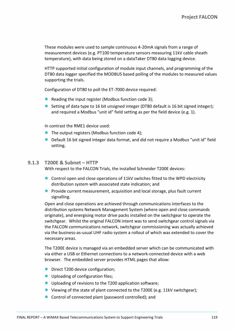
Project FALCON
FINAL REPORT – A WiMAX Based Telecommunications System to Support Engineering Trials 119
These modules were used to sample continuous 4-20mA signals from a range of measurement devices (e.g. PT100 temperature sensors measuring 11kV cable sheath temperature), with data being stored on a dataTaker DT80 data logging device.
HTTP supported initial configuration of module input channels, and programming of the DT80 data logger specified the MODBUS based polling of the modules to measured values supporting the trials.
Configuration of DT80 to poll the ET-7000 device required:
Reading the input register (Modbus function code 3);
Setting of data type to 16 bit unsigned integer (DT80 default is 16 bit signed integer); and required a Modbus "unit id" field setting as per the field device (e.g. 1).
In contrast the RME1 device used:
The output registers (Modbus function code 4);
Default 16 bit signed integer data format, and did not require a Modbus "unit id" field setting.
9.1.3 T200E & Subnet – HTTP With respect to the FALCON Trials, the installed Schneider T200E devices:
Control open and close operations of 11kV switches fitted to the WPD electricity distribution system with associated state indication; and
Provide current measurement, acquisition and local storage, plus fault current signalling.
Open and close operations are achieved through communications interfaces to the distribution systems Network Management System (where open and close commands originate), and energising motor drive packs installed on the switchgear to operate the switchgear. Whilst the original FALCON intent was to send switchgear control signals via the FALCON communications network, switchgear commissioning was actually achieved via the business-as-usual UHF radio system a rollout of which was extended to cover the necessary areas.
The T200E device is managed via an embedded server which can be communicated with via either a USB or Ethernet connections to a network-connected device with a web browser. The embedded server provides HTML pages that allow:
Direct T200 device configuration;
Uploading of configuration files;
Uploading of revisions to the T200 application software;
Viewing of the state of plant connected to the T200E (e.g. 11kV switchgear);
Control of connected plant (password controlled); and

Project FALCON
FINAL REPORT – A WiMAX Based Telecommunications System to Support Engineering Trials 120
Download of diagnostic, event and measurement CSV formatted files.
Device configuration was undertaken initially with direct connection of a PC via Ethernet, and ongoing connection was established remotely via the FALCON Communications Network, following T200E functional and access password configuration, and configuration of the Ethernet communications with FALCON network IP parameters.
Stored measured electrical current values where periodically extracted via the appropriate HTML page and subsequently used in technique trial analysis.
Figure 49: Screen Shot of T200E Measurement Data Download
Source: FALCON Project - T200E System
9.1.4 Sub.net – HTTP The eMS Sub.net device is a web-enabled multifunctional substation monitoring instrument. For purposes of the FALCON engineering technique trials the device was used to measure and record 10 minute average values of current, voltage, power, and harmonics.
The Sub.net device is managed via an embedded server which can be communicated with via either an Ethernet connection to a network-connected device with a web browser, or via a modem (not used on FALCON). The embedded server provides HTML pages that allow:
Direct device configuration;
Uploading of configuration files;
Uploading of revisions to the application software;

Project FALCON
FINAL REPORT – A WiMAX Based Telecommunications System to Support Engineering Trials 121
Viewing of real time measured parameters and recorded average values and download of recorded measurement CSV formatted files (See Figures).
Figure 50: Sub.net Device - Configuration of FALCON Network IP Parameters
Figure 51: Sub.net Device - Real Time Parameter Display
Source: FALCON Project Source: FALCON Project
Device configuration was undertaken initially with direct connection of a PC via Ethernet (cross-over cable), and ongoing connection was established remotely via the FALCON communications network, following functional and access password configuration, and configuration of the Ethernet communications with FALCON network IP parameters.
Figure 52: Sub.net Device - Display of Recorded Measured Values
Figure 53: Sub.net Device - CSV File Download
Source: FALCON Project Source: FALCON Project
9.1.5 P341 DAR Relay & P141 Protection Relay – IEC 61850 MMS Initial device configuration of Ethernet communication parameters via was completed via serial connection using device manufacturer’s software (Micom S1 Agile engineering tool suite). An Ethernet connection to the device via the FALCON communications network was then used for further functional device configuration using the engineering tool suite.

Project FALCON
FINAL REPORT – A WiMAX Based Telecommunications System to Support Engineering Trials 122
Simple IP parameter setting within the OPC software was made to establish device connection; and subsequent parameter selection in the OPC software configured logging of data.
9.1.6 P141 Protection Relay – IEC 61850 GOOSE This activity was delayed and is to be conducted in a forthcoming activity.
9.1.7 P847 PMU relay & Windows based PDC software – IEEE 37.118 Initial P847 Phasor Measurement Unit (PMU) device configuration of Ethernet communications was achieved via serial connection using device manufacturer’s software. Phasor data concentrator software was then configured for communications connection to the P847 devices, and capture of real-time phasor information.
9.1.8 Energy Storage Controllers – RDP & DNP3 The energy storage systems have three basic elements that make up the control system illustrated below.
Figure 54: Energy Storage Systems - Overview of Controller Devices
Source: FALCON Project
These elements are:
The Battery Management System – software hosted on a windows-based PC providing overall supervision and control of the five module battery system. Each of the five

Project FALCON
FINAL REPORT – A WiMAX Based Telecommunications System to Support Engineering Trials 123
battery modules has its own controller providing supervision and control of an individual 20kWh battery module;
Inverter controller – integral to the inverter hardware is the controller running software that takes system measurements and operates the inverter based on parameters stored within the controller, and set-points and control parameters passed to it by the site controller;
Site controller – software hosted on a windows-based PC providing overall supervision and control of the assembled devices. The software provides virtual “devices” that represent either physical devices (e.g. the inverter) or control functions (e.g. peak shaver). The system is controlled via these device interfaces either through direct input of an operating set-point (e.g. 50kW, positive number representing discharge), or though the input of a control set-point (e.g. 180kW peak shaving threshold).
The three main control elements are inter-connected via dedicated Ethernet local area network. In addition, the Battery Management PC and the Site Controller PC are each separately connected to the FALCON communications network via the local FALCON CGR router in the substation.
This (FALCON) wide area network connection allows remote connection to the Site Controller application for comprehensive control and supervision of the energy storage system. This connection is most simply affected using the native Windows accessory Remote Desktop Connection (utilising Microsoft RDP).
Figure 55: Energy Storage Systems - Site Controller Software
Source: FALCON Project

Project FALCON
FINAL REPORT – A WiMAX Based Telecommunications System to Support Engineering Trials 124
Figure 56: Energy Storage Systems - Battery Controller Software
Source: FALCON Project
The Site Controller software also implements a DNP3 virtual device, effectively providing a control interface for the electricity network management system PowerOn Fusion (GE). This virtual device acts as a DNP3 outstation/remote terminal unit, providing data representing operating status of the energy storage system, and receiving operating set-points from the network management system to control the energy storage system.
Also installed on the site controller PC is a bespoke piece of software, the “DNP3 Dashboard”. This software controls the energy storage system via DNP3, and demonstrates control functionality via a remote network control system. A screenshot of the DNP3 Dashboard is shown below.

Project FALCON
FINAL REPORT – A WiMAX Based Telecommunications System to Support Engineering Trials 125
Figure 57: Energy Storage Systems - Screenshot of DNP3 Dashboard Application on Site Controller PC
Source: FALCON Project
Whilst DNP3 control functionality, and remote control, have both been demonstrated throughout the technique trial, the energy storage system has not been connected to the electricity Network Management System.
9.1.9 Tollgrade Aggregators – HTTP & SSH The Tollgrade Lighthouse Sensors illustrated below are inductively powered devices that measure current, conductor temperature and electric field strength (proxy for voltage), and signal these values via IEEE 802.11 b/g WiFi to a locally mounted Tollgrade Aggregator. The aggregator is a web-enabled device that manages onward transmission of measured values, analytical and status information from the OHL devices to the LightHouse Sensor Management System (SMS) software running on a Linux-based PC.

Project FALCON
FINAL REPORT – A WiMAX Based Telecommunications System to Support Engineering Trials 126
Figure 58: Tollgrade Lighthouse MV Sensor
Source: FALCON Project
The Lighthouse sensors are used as part of the 11kV overhead line dynamic asset rating technique trial. The overall scheme for that technique trial is shown below schematically showing the connection between the sensor devices and the “Super Aggregator”. This diagram also illustrates the overall integration of instrumentation with the communications network to support the technique trials.

Project FALCON
FINAL REPORT – A WiMAX Based Telecommunications System to Support Engineering Trials 127
Figure 59: Device Inter-connection for 11kV Overhead Line Dynamic Asset Rating Trial
Source: FALCON Project

Project FALCON
FINAL REPORT – A WiMAX Based Telecommunications System to Support Engineering Trials 128
SECTION 10
10 Comparison to Existing Systems

Project FALCON
FINAL REPORT – A WiMAX Based Telecommunications System to Support Engineering Trials 129
10.1 Scanning UHF Radio The current BAU solution in WPD uses Trio UHF Radios supplied by Wood and Douglas for SCADA. Models used are ER450/EH450 for the South West and Wales region and ER45e/EH45e for the Midlands region of WPD. The main difference is that the South West and Wales had the earlier version where two RS232 ports were used, and the Midlands have the newer units where one of the RS232 ports is replaced by an RJ45 Ethernet Port. These radios are IP over serial and not IP radios.
The maximum data rate available for current operational use (as licenced) which currently carry the Scanning Telemetry Power ON Fusion Data Traffic for WPD is 9600 Bit/Sec within 12.5 KHz channel spacing. There is technically a possibility to combine two channels giving 19200 Bit/Sec within a 25 KHz channel spacing but there is no licence to operate at this capacity. This is the ETSI standard.
This can be contrasted with a 10MBPS capability on the FALCON WiMAX based radio network.
With respect to the wider merits and shortcomings of the two different networks of WiMAX and Traditional UHF radio communications are listed below:
UHF Pros
Tried and tested reliable communications medium;
Very good coverage and reach;
Good resilience to rain fade during inclement weather;
Existing UHF licences in place with WPD owning additional licences for future requirements;
Well understood by the business with procedurised rollout capability.
UHF Cons
Poor (low) bandwidth capabilities;
Data rates are slow for future smart grid requirements where speeds in Megabits per second rather than the kilobits per second range are necessary;
Latency increase with increase in site density;
Poling or scan rate increases in duration with increase in number of sites off one scanning site (Increase in Latency);
Large antenna requirements to achieve the required gain in distant locations;
Near Line of Sight requirements but not as restrictive as higher frequencies in the low microwave bands.
WiMAX Pros
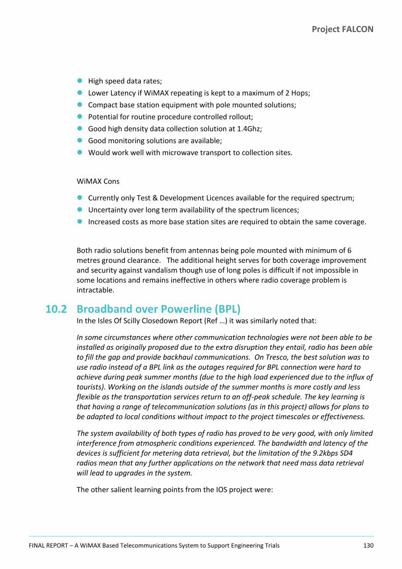
Project FALCON
FINAL REPORT – A WiMAX Based Telecommunications System to Support Engineering Trials 130
High speed data rates;
Lower Latency if WiMAX repeating is kept to a maximum of 2 Hops;
Compact base station equipment with pole mounted solutions;
Potential for routine procedure controlled rollout;
Good high density data collection solution at 1.4Ghz;
Good monitoring solutions are available;
Would work well with microwave transport to collection sites.
WiMAX Cons
Currently only Test & Development Licences available for the required spectrum;
Uncertainty over long term availability of the spectrum licences;
Increased costs as more base station sites are required to obtain the same coverage.
Both radio solutions benefit from antennas being pole mounted with minimum of 6 metres ground clearance. The additional height serves for both coverage improvement and security against vandalism though use of long poles is difficult if not impossible in some locations and remains ineffective in others where radio coverage problem is intractable.
10.2 Broadband over Powerline (BPL) In the Isles Of Scilly Closedown Report (Ref …) it was similarly noted that:
In some circumstances where other communication technologies were not been able to be installed as originally proposed due to the extra disruption they entail, radio has been able to fill the gap and provide backhaul communications. On Tresco, the best solution was to use radio instead of a BPL link as the outages required for BPL connection were hard to achieve during peak summer months (due to the high load experienced due to the influx of tourists). Working on the islands outside of the summer months is more costly and less flexible as the transportation services return to an off-peak schedule. The key learning is that having a range of telecommunication solutions (as in this project) allows for plans to be adapted to local conditions without impact to the project timescales or effectiveness.
The system availability of both types of radio has proved to be very good, with only limited interference from atmospheric conditions experienced. The bandwidth and latency of the devices is sufficient for metering data retrieval, but the limitation of the 9.2kbps SD4 radios mean that any further applications on the network that need mass data retrieval will lead to upgrades in the system.
The other salient learning points from the IOS project were:
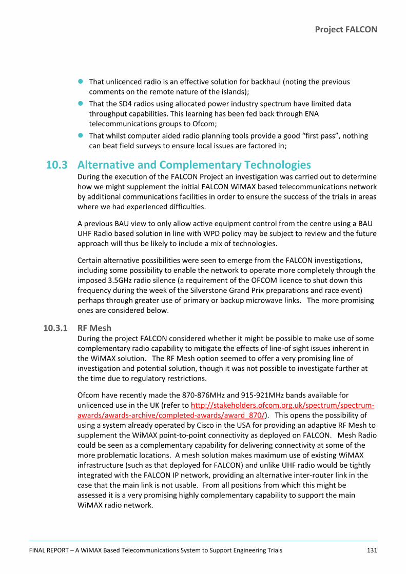
Project FALCON
FINAL REPORT – A WiMAX Based Telecommunications System to Support Engineering Trials 131
That unlicenced radio is an effective solution for backhaul (noting the previous comments on the remote nature of the islands);
That the SD4 radios using allocated power industry spectrum have limited data throughput capabilities. This learning has been fed back through ENA telecommunications groups to Ofcom;
That whilst computer aided radio planning tools provide a good “first pass”, nothing can beat field surveys to ensure local issues are factored in;
10.3 Alternative and Complementary Technologies During the execution of the FALCON Project an investigation was carried out to determine how we might supplement the initial FALCON WiMAX based telecommunications network by additional communications facilities in order to ensure the success of the trials in areas where we had experienced difficulties.
A previous BAU view to only allow active equipment control from the centre using a BAU UHF Radio based solution in line with WPD policy may be subject to review and the future approach will thus be likely to include a mix of technologies.
Certain alternative possibilities were seen to emerge from the FALCON investigations, including some possibility to enable the network to operate more completely through the imposed 3.5GHz radio silence (a requirement of the OFCOM licence to shut down this frequency during the week of the Silverstone Grand Prix preparations and race event) perhaps through greater use of primary or backup microwave links. The more promising ones are considered below.
10.3.1 RF Mesh During the project FALCON considered whether it might be possible to make use of some complementary radio capability to mitigate the effects of line-of sight issues inherent in the WiMAX solution. The RF Mesh option seemed to offer a very promising line of investigation and potential solution, though it was not possible to investigate further at the time due to regulatory restrictions.
Ofcom have recently made the 870-876MHz and 915-921MHz bands available for unlicenced use in the UK (refer to http://stakeholders.ofcom.org.uk/spectrum/spectrum-awards/awards-archive/completed-awards/award_870/). This opens the possibility of using a system already operated by Cisco in the USA for providing an adaptive RF Mesh to supplement the WiMAX point-to-point connectivity as deployed on FALCON. Mesh Radio could be seen as a complementary capability for delivering connectivity at some of the more problematic locations. A mesh solution makes maximum use of existing WiMAX infrastructure (such as that deployed for FALCON) and unlike UHF radio would be tightly integrated with the FALCON IP network, providing an alternative inter-router link in the case that the main link is not usable. From all positions from which this might be assessed it is a very promising highly complementary capability to support the main WiMAX radio network.

Project FALCON
FINAL REPORT – A WiMAX Based Telecommunications System to Support Engineering Trials 132
Cisco already have FALCON type CGR 1240 router modules available. These work in what was classically called the US radio band in the 900Mhz range (in fact this is wider than the European band and is at 902-928Mhz). The 800MHz range (870-876Mhz) was classically referred to as the European band. By utilising the newly available 916 – 921 MHz band and thus existing Cisco equipment, a FALCON RF Mesh solution could have been enabled within a very short timescale.
The mesh design allows CGR routers to interconnect on the new frequency, finding for themselves in a dynamic way the best inter-secondary site links that provide a pathway back to the local base station/primary. It can also be implemented conveniently on just a subset of the substations with hops of up to seven substations being theoretically possible. However there are a number of disadvantages of having too many mesh hops:
1. Latency is increased and may become unusable for e.g. commanding / control purposes;
2. Aggregation of data (piling up) on popular links back to a routing node may limit throughput;
3. System resilience may be affected if too many nodes are dependent on a given routing node.
However the routing is adaptive and the routes/links can be weighted to prefer better links unless these are not available. Regarding antennas it is possible to use the small omni antenna for mesh (as already used for WiFi) otherwise a bulkhead connector and an external omni antenna could be added.
While not currently quantified, the penetration characteristics of the frequency band are better than the WiMAX access frequency (900 as opposed to 1400MHz) but the RF Mesh gives the ability to mesh and hop (relay) back to the base station so does give the project a viable option for the sights where line-of-sight to the base station is a problem (as now).
10.3.1.1 Regulatory Considerations For the preparation of this issue of the options paper, the JRC were approached to obtain some guidance in respect of the regulatory position and make them aware that the FALCON Project was considering this option. The JRC view was however discouraging, having checked the Cisco specification for the solution and taking previous history in this area they were not able to advise a clear way forward using the US Band and available Cisco hardware. This would point to the need for Cisco to develop a solution compatible with the European band, a result which immediately puts this option out of scope due to the lengthy timescales of such a development.
Project FALCON
FINAL REPORT – A WiMAX Based Telecommunications System to Support Engineering Trials 133
SECTION 11
11 Overall Project Conclusions

Project FALCON
FINAL REPORT – A WiMAX Based Telecommunications System to Support Engineering Trials 134
As noted in the introduction, the FALCON WiMAX pilot rollout was time and budget constrained and so it is not fair to assess this solely against fully funded and deployed BAU solutions. The FALCON Project communications workstream, by its nature, took a route which flushed out a significant amount of learning which might not otherwise have been found and established a good working telecommunications system capable of supporting the FALCON trials. A solution having a more complete radio coverage pattern would certainly not have observed several of the issues that were seen in practice on FALCON. In this then, the FALCON Project has been a success in finding and documenting these items for consideration by others who may be thinking of a similar implementation.
This section presents the specific project conclusions and also makes a number of recommendations.
11.1 Specific Conclusions Our observations of the behaviour of the WiMAX radio system and the FALCON communications system overall are as follows:
1. A good signal facilitating reliable IP level communications with WiMAX based radio systems is best achieved with a clear line of sight – best examples of good connectivity were seen where the substation and base station were across an open valley from each other. Clearly there is less clutter (buildings, trees, topological features) along such open lines-of-sight. Relating and comparing this to typical microwave technologies, where the only communication link option is to have clear line of sight with no breach of the Fresnel zones, WiMAX radio technology is more flexible and will work under non line-of-sight conditions. This was clearly evidenced on the FALCON Project;
2. With an open unhindered line of sight WiMAX can have a significant range (the project noted a usable link (RSSI -82bD) could be maintained between Moulsoe Church and Horwood at a range of 14.9km) against a quoted working guideline of 1-2km;
3. Where there is no clear, unobstructed line of sight between the substation and the base station the strategy must be to establish one. This will usually mean to gain height where possible and avoid obstructions such as buildings and/or trees. Given that the base station is likely to be fixed and in place early in the rollout, this means installing a high pole for the antenna mount at the substations;
4. Further to the above points, the best signal for communications to the substations was not necessarily always established using the closest base station. Even distant base stations (at workable ranges of 5-7 km) with clear lines of sight sometimes proved a better connection option than a close base station (1-2km) having a poor line of site to the location under consideration;
5. A strong radio signal, even with good signal to noise parameters, does not necessarily result in good communications at IP level. In particular the antenna bearing seems critical to achieving a good usable signal for the IP level;
6. A radio signal which is too strong (better than -40 dBm) can also be a significant issue, as was seen in the primary site radio links implemented via CPE devices and for

Project FALCON
FINAL REPORT – A WiMAX Based Telecommunications System to Support Engineering Trials 135
substations closer to the base station than around 400m. In such cases fitting of radio attenuation devices to obtain a signal somewhere around -55dBm was found to be very effective. Depointing the antennas was not effective – resulting in noisy signal (i.e. extended packet times and losses) at IP level;
7. At sites with both a direct line of sight radio path and a reflected path of similar received signal strength problems may arise. If the antenna is panned into the reflected path signal the interaction between both the reflected and direct radio signal paths seems to cause problems with the IP layer experiencing time outs, high latency and packet drops. In a situation like this the Project noted that if the site antenna is re-panned onto the direct signal path, the IP layer connectivity improved dramatically and this in turn improved IP stability, reducing packet drops and latency;
8. The project found evidence of poor reception in regions around very large buildings, not purely attributable to blocked lines of sight. Several substations in the environs of the MK Dons Stadium experienced difficult communications (ASDA Store, JJB Sports) where this would not normally be expected and the antennas had to be pointed off the nominal bearing to the local base station to obtain a usable signal. The same effect was seen in the area around the Milton Keynes XScape Ski Dome (another very large building) and the tall Stephenson House building in Bletchley. More in depth follow up investigation is recommended to determine more about the problem in such cases, FALCON did not have the necessary expertise and equipment to do this within the Project scope;
9. Radio interference is an issue. This was seen where multiple base stations were roughly aligned along the same line of sight both in the same direction but also in front and behind the substation in question;
10. Where radio interference is present, the measured RSSI at the location suffering the interference may have a higher value than expected due to the additive effect of the interfering signals. This can be misleading, especially initially until the presence of interference has been established. Stronger signals are usually better, but with interference (especially if undetected) this may not necessarily be advantageous and a correct indication of the site status;
11. Radio interference can be alleviated by the following means:
a. Using attenuation. This may be applicable in situations where it is possible to take one of the interfering signals below some threshold;
b. By re-aligning the antenna bearing – to point away from the less desirable signal or perhaps even to choose a totally different base station.
12. For a misaligned antenna, the pickup off the back of an antenna pointing on a bearing
180 off the correct azimuth is around 20dB below the signal received from the front of the antenna;
13. The project was only able to use 3 distinct WiMAX frequencies in the 1.4GHz band to be spread around the base stations so that adjacent cells were not operating on the same frequency and so reduce the chances of interference. The project saw several cases of interference however even over quite large distances of separation, and we

Project FALCON
FINAL REPORT – A WiMAX Based Telecommunications System to Support Engineering Trials 136
conclude that a greater number of frequencies would thus have offered a far better solution less prone to interference;
14. Key to solving radio issues in the FALCON WiMAX system (and it is expected to be more generally the case) was understanding the root cause of the problem. This Report provides details of the issues seen and in most cases resolved by the project, and this understanding process and knowledge should be useful for other projects in the future;
15. With the modernisation of the electricity distribution grid, the complexity of power system installations will increase. New functions will be introduced and more devices integrated in order to achieve truly distributed intelligence. In parallel, many more interconnected systems will be rolled out and operated. This raises the bar for robust, extensive security architectures. Resilience and survivability are important quality attributes for mission critical installations. New technologies such as "behaviour based security", domain specific anomaly detection and device virtualisation need to get integrated. Networks, devices and security installations must react "intelligently" and be resilient to attacks in order to survive and keep our energy supply secure and stable while the designs are sensitive to enhancements such as closed loop tele-protection;
16. It is sometimes very difficult to isolate a fault and be specific about where in the overall communications system its causes were located. This meant that once initial investigative work had been completed by the project it was necessary to involve specialist support from both Cisco and Airspan, sometimes with these parties acting cooperatively to resolve the matter;
17. The project selected the Bradwell Abbey Bulk supply point/Primary as the central area network aggregation point terminating the onward microwave link to Horwood. This was done partly because of the availability of the tower at Bradwell Abbey giving extra height for the link. However not all the FALCON Primary sites could establish a usable 3.5GHz backhaul link to Bradwell Abbey and were connected instead directly to Horwood. A different choice of aggregation site in the central Milton Keynes area may therefore have been beneficial to the project;
18. More base stations deployed around Milton Keynes on unobtrusive 15m wood poles would almost certainly have given a better 1.4GHz coverage capability to the FALCON network rather than deploying these to a limited number of WPD primaries involved directly with the FALCON trials;
19. A typical round trip time latency for substations attached to the 3.5GHz backhaul of the FALCON FAN was measured at around 105ms in cases where there was no relay leg on the path. In cases with a single relay the RTT latency rose to around 125ms. For substations attached directly to the main aggregation points, the RTT latency was measured at around 73ms at the furthest downstream location (Horwood) and 85MS when attached to the microwave link (Bradwell Abbey). These findings confirm the metric from Airspan that each additional hop in the communications path adds an additional 20ms to the RTT latency;

Project FALCON
FINAL REPORT – A WiMAX Based Telecommunications System to Support Engineering Trials 137
20. One obvious conclusion from the above would be to attach substations as close as possible to a network aggregation point, and to design for this to be realised, making best use of microwave and 3.5GHz WiMAX links;
21. The design of any teleprotection solution requires, for minimum (i.e. usable) latency to be achieved, that the communicating end units be attached to the same radio base station. Careful attention to achieving such local connectivity would need to be paid during the initial rollout of the participating substations in the teleprotection scheme as well as the provision of suitably located base stations for ensuring this as FALCON saw instances of geographically close substation locations connecting to different base stations (based on local radio conditions which can change rapidly even over short distances). Thus, it cannot be simplistically assumed that all geographically close substations attach to a specific local base station.
11.2 Specific Recommendations 1. Base stations should be installed with the highest possible antenna mountings in place
early on. The minimum height which should be considered is 15m but more height will ensure less problems with secondary site connectivity later. Clearly local conditions need to be factored in to this basic recommendation;
2. A cost/benefit analysis should be carried out before any future systems are deployed to consider the possibilities for the use of alternative base station hosting locations and to determine the best approach to the deployment of these;
3. Because of the restrictions in the FALCON operating “test” licence, the project was obliged to operate without the 3.5GHz backhaul infrastructure element for one week in each year12. During this interval it was the case that sites connected to the main WPD spine network via microwave link (directly at Horwood radio tower and those secondary sites connected to Bradwell Abbey) remained usable. This led us to conclude that backhaul infrastructure based on Microwave links would have been better for FALCON and could be considered in other cases;
4. In cases where there may not be blanket radio coverage, when choosing where to locate sites (if this luxury is a possible option), installers should pay attention to both the communications capability at that location as well as to the suitability of the location in electrical distribution network terms. The communications capability should be validated where possible before any actual deployment to that location is made. This approach does require more initial planning but avoids the possibility of a later situation arising where a site (at which considerable investment may have been made) cannot be brought up on the network. This clearly does not apply for a full BAU rollout where coverage needs to be obtained wherever needed. The fact that some sites needed to be abandoned and replaced by others because of unsuitable radio coverage is a reflection of the fact that FALCON was a technology evaluation “pilot” project with a limited budget and timescale. For a full BAU rollout this
12
Silverstone British Grand Prix.

Project FALCON
FINAL REPORT – A WiMAX Based Telecommunications System to Support Engineering Trials 138
situation should not arise if the various recommendations that have emerged from the project are followed;
5. In a WiMAX radio network implementation ensure that the base station nodes which create the backhaul spine to the system are rolled out and brought online first. Then before any equipment is rolled out to any substations, conduct drive around tests to establish the coverage profile based at the deployment locations based on real world radio reception measurements. Additional base stations should be added as necessary to provide coverage for any blind spots and the network tuned. This therefore forces significant additional work early in the project, but it is believed that this will have the effect of significantly reducing difficulties with radio coverage later;
6. Site rollouts, particularly for a large programme of work, should be meticulously planned, tracked and optimised so that the number of visits to each site are limited. Subcontractors could be incentivised with payment linked to completed activities (verified site deployments establishing that acceptable radio parameters are established). Teams could be encouraged to take ownership of their piece of work and pass sufficient coordination instructions to the following teams. Work directions should be documented, tested (proven) and repeatable;
7. Our findings suggest that placement of certain communications equipment in close proximity to 132KV conductors can in some cases result in interference with the operation of this equipment (the particular example being the GPRS time synchronisation signals needed to operate the WiMAX TDM based system). It is therefore recommended that specific attention is directed at placing radio equipment away from such potential sources of interference;
8. Any antennas mounted on long poles need to be cross braced to prevent excessive vibration to the antenna noted during even moderate breezes;
9. Where a choice of the type of pole is possible for a small substation deployment (cranked vs straight) a straight pole is preferable as these allow for ready adjustment of the antenna bearing if this is required at a later time;
10. Assess all WiMAX substation sites fully before installing any equipment there even to the extent of considering transitory factors such as parked delivery lorries in commercial locations. These may not be present when the assessment is done so there needs to be intelligent consideration of such additional possibilities;
11. Implementers should avoid co-channel interference by pointing a secondary substation antenna close to the bearing of the required base station but away from the distant (not required – interfering) base station where these lines of sight are close to each other13. Thus align the antenna away from the non-required base station consistent with still receiving a good signal from the required one. An alternative may be to reduce the interfering signals by attenuation (on Falcon 10 dB and 20dB attenuators were fitted in different circumstances) such that one of these is
13
Noting that the alignment can be to the front of OR BEHIND the antenna in question (180 away from the main line of sight onto the back of the antenna)
Project FALCON
FINAL REPORT – A WiMAX Based Telecommunications System to Support Engineering Trials 139
reduced below a level where it is a problem. The project evidenced good results at one problem substation in particular;
12. Even when the radio signal parameters show good values, the accuracy of the antenna bearing should still be verified as even a misaligned antenna can send/receive a seemingly good signal although this may be unusable at the IP level. This should be done anyway as a non-optimally pointed and tuned in substation node may step up its power to try to work and may thus cause problems for other attached substations on the same base station. Such tuning and optimisation should not be overlooked. In summary, a simple view of the radio parameters that indicate that a site is adjusted to an acceptable level, does not always mean that this will be the case at the IP level, and the quality of reflected and/or off-beam signals in the cases that we investigated has therefore found to be questionable for the communication purposes of the FALCON Project;
13. When measuring or determining antenna bearings in substations, be aware of the presence of magnetic fields which can distort measurements using a magnetic compass. Disturbance may occur from transformers and underground/overhead cables and other magnetically noisy equipment such as motors and even (and powerfully at close range) mobile phones. Confirm results using multiple tools and then follow the approach of panning in the antenna to obtain the best radio signal giving usable IP level connectivity;
14. Pay attention to the placement of radio equipment in substations near other organisations as there is potential for interference (in either direction). Even if not on the same operating frequency there can be harmonics and breakthrough at different frequencies where signal levels are particularly high;
15. FALCON radio statistics analysis provided a simple diagnostic tool for identifying problem substations, particularly during rollout. Simply collect the radio stats for a suitable interval (several days recommended) for all sites, average the RSSI (signal strength) and CINR (signal to noise) values, plot these, and concentrate investigation on those not falling on the line (see Section 5.4.1);
16. The FALCON Project diagnostic method for plotting average signal parameters (RSSI/CINR) for all substations could readily be packaged and used as a diagnostic tool forming part of any future radio installation process. Refer to Section 5.4.1;
17. When making adjustments in the field to antenna pointing and selection of the best signal to use at problem locations, a coordinated attack with support from central monitoring facilities is advantageous. Feeding back results and giving instructions to the engineers allows all monitoring capabilities to be leveraged to advantage as the tools available in the field are limited. Extended follow up monitoring is also recommended to be sure that the system was not just caught at a good time.
11.3 Reasons for Poor Radio Connectivity One or more of the following were found in practice during FALCON installation and operations. In combination these issues proved very detrimental to reception:

Project FALCON
FINAL REPORT – A WiMAX Based Telecommunications System to Support Engineering Trials 140
Poor location, fixed aspects:
– In a dip/valley shaded from base station or behind a hill;
– Line of sight to base station obscured by houses, buildings. Mitigate by choosing alternative base station if possible, and selection of where on the substation to locate the antenna for maximum clear view.
Poor location, transitory aspects:
– Line of sight to base station affected by foliage (trees, bushes etc) especially deciduous varieties in the short range;
– Line of sight sometimes obscured by parked vehicles (delivery lorries etc) – mitigate by selecting base station in direction away from threat or taller antenna mount;
– Line of sight becomes obscured by building works occurring after installation (may be unknown until the signal drops).
Incidents:
– Fire (Ashlands stadium) resulting in complete loss of substation. The fire was not FALCON related and was established to have been caused by vandalism;
– Suspected knock to antenna from high sided lorry resulting in misalignment of antenna (Oxford St. Bletchley);
– Vandalism (petty or severe) causing degradation through damage or misalignment of antennas. An example of petty vandalism: using the antenna for target practice (Moor Park Bletchley).
Equipment issues:
– WiMAX cards faulty;
– Router faulty;
– Cable joints/terminations not water proofed.
Installation issues:
– Best base station (where options exist) not chosen;
– Antenna not high enough (see above re: hazards);
– Antenna bearing not optimal (or even way off beam) may cause poor signal OR poor IP level communications even for apparently good signal levels;
– Cabling not terminated correctly (bad jointing);
– Selecting a poor quality reflection in preference to a weaker direct signal (basing decision making on radio stats only);
– Omitted or poor quality weather proofing (sealant) etc.
Other transitory effects:
– Co-channel radio interference – line of sight taking in two or more base stations;
– Weather events (wind blowing antennas/causing these to oscillate or move), heat (sun on unventilated housings causing items to overheat); rain (signal attenuation, especially when moisture is collected on immediate Line-of-Sight foliage).

Project FALCON
FINAL REPORT – A WiMAX Based Telecommunications System to Support Engineering Trials 141
The table below identifies the sites that were abandoned by the project as unusable and gives the reasons for the decision.
Location Type Comments
Ashlands Stadium LVM Substation and all deployed equipment destroyed by fire (arson) and deemed too risky to reuse reinstated location.
Mori Seki Tongwell T.2.1 Site access was blocked by the company at that location and since the FALCON installation was not able to be classified as an emergency situation, WPD resorted to legal clarification. This unfortunately took so long that plans to use this site had to be abandoned.
Wing Road Stewkeley T.2.4 Site on the edge of the trials area and no radio survey signal was found even at 6m height. A possible move to scanning radio was comnsdired but as no engineering install done this site was abandoned as too difficult at the trials area limit.
Grasscroft Furzton LVM, T.1.4
No usable WiMAX signal could be obtained at Grasscroft. Role of LVM And T1.4 removed to Granby Court.
Stephenson House Bletchley LVM Substation is located behind a large tower block (offices) and no signal detected.
Stantonbury Farm Gr Linford LVM Not deployed in the end.
Oliver Rd Bletchley LVM The best WiMAX signal obtained at this location was -92 dB which was unusable. Impractical to install a longer pole to this location.
Shackleton Place Oldbrook LVM Full radio inspection survey was done at this site with pump up antenna. Best signal was -92dbm even at 6 metres height.
Arena Park Bletchley LVM WILL NOT CONNECT SIGNAL -91DBM. High ground between here and Bletchley and also to Newton Rd. Bearing to Bletchley 350deg, 1860m. To Newton Rd 241deg 1099m. Pump up mast 17/1/14 shows no hope. Abandon.
Wincanton Hill Railway Farm LVM This site which was on the lea side of a hill in respect of the base stations it might have seen was initially connected, but with a poor quality signal fluctuating between -84 and -94 and with a long term deterioration present. Consequently vitually no connectivity was recorded and no monitoring data could be collected. On inspection it was found that an large house extension was being built in one of the line of sight directions. Given the topology and the difficulties envisaged installing a much taller pole to this residential site, it was decided to abandon the location.
Woad Farm Cottages Weston Underwood
LVM Nothing was ever seen from this location which was on the extreme limits of the trials area at 2, 4.5 and 5km from potential base stations. Being pole mounted it was also difficult to adjust as not only were Linesmen required but the access to the pole was challenging with the main access point being limited by the presence of a drainage ditch and at the side of a busy road. When a line team did manage to

Project FALCON
FINAL REPORT – A WiMAX Based Telecommunications System to Support Engineering Trials 142
Location Type Comments
pan the antenna onto the best bearings there was still no signal. The site was abandoned. Some time later a possible source of problems was found during inspection of IPSEC tunnel settings. This site had no entry. However this would not have accounted for the lack of radio connectivity at that level.
Old Groveway Simpson LVM This site was located in a small dip in the land and was unfortunately placed looking along a long grove of trees towards the most convenient base station for radio connectivity. Some success was obtained looking for signal on a 6m test pole but even then the signal was still marginal and the difficulties of introducing a long pole in a residential setting were not considered being worth the expensiture of time and cost.
11.4 Wider Application of WiMAX Technology for DNO Communications It is a primary objective of the FALCON Project to make learning gathered in the course of the work done and from the execution of the trials themselves available to the wider industry. At the first level the question to be answered is whether WiMAX offers a suitable technology for use by utilities, and specifically DNOs, for implementing a reliable substation communications network.
This assessment clearly needs to be carried out against competing technologies.
There will always be pitfalls inherent in trying to extrapolate a small scale trial up to the sort of scales relevant to DNOs or similar organisations but clearly there are inputs from these trials which can usefully inform the decision making process. Some of the conclusions from the FALCON trials specific to the communications workstream are therefore listed here.
A bespoke WiMAX radio based telecommunications system based on commercial components from Cisco and Airspan used to support the operations of an electricity smart grid has been deployed in Milton Keynes as part of the project FALCON implementation work. WiMAX has proved to be a suitable radio technology for this application yielding a low overall installation and operational cost solution while giving high levels of control to the DNO when compared to other alternative candidate solutions such as fixed line;
WiMAX radio is implemented using AIRSPAN radio units coupled with ruggedized Cisco Router technology for the IP routing capability. This offers a resilient IP network solution for use by utilities and others where site access and installation may be an issue, and particularly for locations where there is no existing telecommunications infrastructure;
A low latency solution may be implemented by minimising the number of routing node hops necessary to communicate with terminating equipment. Where additional

Project FALCON
FINAL REPORT – A WiMAX Based Telecommunications System to Support Engineering Trials 143
hops are necessary in the link path due to coverage considerations, the solution still provided a low latency capability for the FALCON trials network and the same can be expected for other implementations. This allows a teleprotection scheme between secondary substations to be run over the WiMAX network;
The use of half duplex communications on the radio links is not inconsistent with the typical network traffic consisting of mainly small SCADA data packets;
Alternative bearings for any given site are highly likely to be available in a grid implementation of the type supported by the FALCON electricity distribution and matching telecommunications routing networks. This may result in more distant links and high gain antennas may be required to support such alternate routings where line-of-site issues exist (if directing a link towards a distant aggregation site, see next);
Rather than implementing additional hops in most cases, on the FALCON Project, the radio coverage permitted the direct communication between the distant Horwood location and the primaries affected by line of sight issues to the closer aggregation site at Bradwell Abbey;
The nature of the WiMAX radio solution for telecommunications support infrastructure for an electricity smart grid environment readily lends itself to adaptation and adjustment in the field should expected theoretical signal coverage not be realised. This is primarily due to the number of alternate relay locations that are likely to be present;
The cost of the rugged WiMAX radio based solution for Project FALCON is modest when compared to the likely costs for an IP network infrastructure based on fixed line telecommunications. However the potential licence costs associated with extending the use of the WiMAX solution from test to full operations is not factored into this assessment as it is currently unknown;
It would be advantageous to utilities and other critical national infrastructure organisations to have access to a WiMAX / 1.4GHz frequency solution. Representations are being made in this respect through the JRC.
11.5 What Next for the FALCON WiMAX Network WPD is considering what to do now with the FALCON trials equipment and telecommunications network and has options going through the bid process at the time of writing. At least one follow-on possibility - the Telecoms Templates project, if accepted, is planned to cover deployment and checkout of the latest technology radio options for Low Carbon Smart Grid Networks. During the initial meetings it was identified that some of the existing Low Carbon network Infrastructure such as that put in place by FALCON would lend itself to the Telecoms Templates project rather than just being decommissioned especially when it is recalled that these have already financed by Ofgem and WPD believes strongly that this would be a significant plus point in favour of this bid submission.

Project FALCON
FINAL REPORT – A WiMAX Based Telecommunications System to Support Engineering Trials 144
Potential use is unconfirmed for now, but possibly includes using the system for further Mesh Network roll out with Cisco and trialling other frequencies to test coverage abilities.
Some of the FALCON recommendations and summary points could also be considered for investigation, including, for example, the introduction of microwave links for backhaul as opposed to simply using the 3.5GHz Airspan links as at present.
Clearly ongoing use of the WiMAX frequencies would be dependent on the authorities granting further Authority to Test licences, and some conclusions to emerge in this regard in terms of their future use within the utilities domain.
11.6 Next Generation FALCON-Type Networks Beyond the potential for extending the existing FALCON network to a wider area within WPD or even beyond, to other DNOs, comes the potential for extending the design to include further telecommunications innovations. We consider a number of options therefore for a next generation FALCON network, one which builds on the FALCON design for future Smart Grid operations.
11.7 WiMAX Frequency Regulatory Policy and Future Plans This section is contributed by the JRC.
Secure and resilient communications form the heart of a modern intelligent grid. Although significant communication paths are based on copper and optical fibre, radio is increasingly being used to provide communications, especially in the ‘last mile’ and where roll-out has to be achieved quickly and flexibly. But radio systems need access to scarce and valuable spectrum in which to operate. All radio spectrum is currently allocated to one user or another, in many cases government.
For the FALCON Project, a radio-based solution was required which provided medium speed data rates combined with medium distance reach and penetration through trees to enable the antennas to be located around ground height (2m) rather than above the tree canopy at 10m. Radio spectrum around 1400 MHz appeared ideal, but needed to be proved in this application.
The radio spectrum holder most amenable to permitting a trial project was the Ministry of Defence (MoD). Since the government has a programme of releasing publically held spectrum for commercial use, MoD were amenable to a trial in their spectrum at 1427-1452 MHz
MoD use this spectrum for a variety of confidential specialised applications, but usage around the UK varies, with the whole of their allocation thought to be used in only one location. MoD therefore agreed to a Limited duration trial.
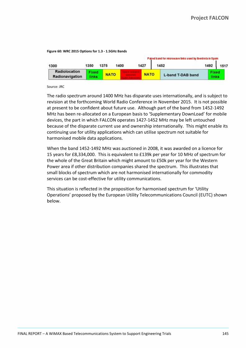
Project FALCON
FINAL REPORT – A WiMAX Based Telecommunications System to Support Engineering Trials 145
Figure 60: WRC 2015 Options for 1.3 - 1.5GHz Bands
Source: JRC
The radio spectrum around 1400 MHz has disparate uses internationally, and is subject to revision at the forthcoming World Radio Conference in November 2015. It is not possible at present to be confident about future use. Although part of the band from 1452-1492 MHz has been re-allocated on a European basis to ‘Supplementary DownLoad’ for mobile devices, the part in which FALCON operates 1427-1452 MHz may be left untouched because of the disparate current use and ownership internationally. This might enable its continuing use for utility applications which can utilise spectrum not suitable for harmonised mobile data applications.
When the band 1452-1492 MHz was auctioned in 2008, it was awarded on a licence for 15 years for £8,334,000. This is equivalent to £139k per year for 10 MHz of spectrum for the whole of the Great Britain which might amount to £50k per year for the Western Power area if other distribution companies shared the spectrum. This illustrates that small blocks of spectrum which are not harmonised internationally for commodity services can be cost-effective for utility communications.
This situation is reflected in the proposition for harmonised spectrum for ‘Utility Operations’ proposed by the European Utility Telecommunications Council (EUTC) shown below.
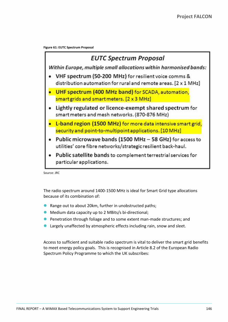
Project FALCON
FINAL REPORT – A WiMAX Based Telecommunications System to Support Engineering Trials 146
Figure 61: EUTC Spectrum Proposal
Source: JRC
The radio spectrum around 1400-1500 MHz is ideal for Smart Grid type allocations because of its combination of:
Range out to about 20km, further in unobstructed paths;
Medium data capacity up to 2 MBits/s bi-directional;
Penetration through foliage and to some extent man-made structures; and
Largely unaffected by atmospheric effects including rain, snow and sleet.
Access to sufficient and suitable radio spectrum is vital to deliver the smart grid benefits to meet energy policy goals. This is recognised in Article 8.2 of the European Radio Spectrum Policy Programme to which the UK subscribes:

Project FALCON
FINAL REPORT – A WiMAX Based Telecommunications System to Support Engineering Trials 147
Figure 62: European Radio Spectrum Policy Programme
Source: JRC
Although 1400 MHz spectrum has been demonstrated as effective by project FALCON, as illustrated in the EUTC spectrum proposal, spectrum at 400 MHz might be able to deliver equivalent benefits, and it is hoped future Network Innovation Projects might enable the range of frequency bands suitable for smart grids to be clarified.

Project FALCON
FINAL REPORT – A WiMAX Based Telecommunications System to Support Engineering Trials 148
Appendices
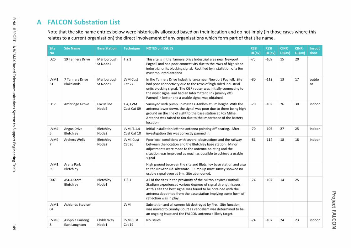
Pro
ject FA
LCO
N
FINA
L REP
OR
T – A W
iMA
X B
ased Tele
com
mu
nicatio
ns System
to Su
pp
ort En
gineerin
g Trials 1
49
A FALCON Substation List Note that the site name entries below were historically allocated based on their location and do not imply (in those cases where this relates to a current organisation) the direct involvement of any organisations which form part of that site name.
Site No
Site Name Base Station Technique NOTES on ISSUES RSSI DL(av)
RSSI UL(av)
CINR DL(av)
CINR UL(av)
In/out door
D25 19 Tanners Drive Marlborough St Node1
T.2.1 This site is in the Tanners Drive Industrial area near Newport Pagnell and had poor connectivity due to the rows of high sided industrial units blocking signal. Rectified by installation of a 6m mast mounted antenna
-75 -109 15 20
LVM131
7 Tanners Drive Blakelands
Marlborough St Node1
LVM Cust Cat 27
In the Tanners Drive Industrial area near Newport Pagnell. Site had poor connectivity due to the rows of high sided industrial units blocking signal. The CGR router was initially connecting to the worst signal and had an Intermittent link (mainly off). Panned in better and a usable signal was obtained.
-80 -112 13 17 outdoor
D17 Ambridge Grove Fox Milne Node2
T.4, LVM Cust Cat 09
Surveyed with pump up mast as -68dbm at 6m height. With the antenna lower down, the signal was poor due to there being high ground on the line of sight to the base station at Fox Milne. Antenna was raised to 6m due to the importance of the battery location.
-70 -102 26 30 indoor
LVM45
Angus Drive Bletchley
Bletchley Node2
LVM, T.1.4 Cust Cat 10
Initial installation left the antenna pointing off bearing. After investigation this was correctly panned in.
-70 -106 27 25 indoor
LVM97
Archers Wells Bletchley Node2
LVM, Cust Cat 20
Poor local conditions with several obstructions and the railway between the location and the Bletchley base station. Minor adjustments were made to the antenna pointing and the situation was improved as much as possible to achieve a usable signal.
-81 -114 18 18 indoor
LVM139
Arena Park Bletchley
High ground between the site and Bletchley base station and also to the Newton Rd. alternate. Pump up mast survey showed no usable signal even at 6m. Site abandoned.
D07 ASDA Store Bletchley
Bletchley Node1
T.3.1 All of the sites in the proximity of the Milton Keynes Football Stadium experienced various degrees of signal strength issues. At this site the best signal was found to be obtained with the antenna depointed from the base station implying some form of reflection was in play.
-74 -107 14 25
LVM104
Ashlands Stadium LVM Substation and all comms kit destroyed by fire. Site function was moved to Granby Court as vandalism was determined to be an ongoing issue and the FALCON antenna a likely target.
LVM88
Ashpole Furlong East Loughton
Childs Way Node1
LVM Cust Cat 19
No issues -74 -107 24 23 indoor

Pro
ject FA
LCO
N
FINA
L REP
OR
T – A W
iMA
X B
ased Tele
com
mu
nicatio
ns System
to Su
pp
ort En
gineerin
g Trials 1
50
Site No
Site Name Base Station Technique NOTES on ISSUES RSSI DL(av)
RSSI UL(av)
CINR DL(av)
CINR UL(av)
In/out door
LVM4 AWA Pumping Station Middleton
Secklow Gate Node1
LVM,T4 Cust Cat 01
This site had a difficult position being on the edge of parkland with many trees and close to a raised Milton Keynes grid road. The line of sight to the closest base station was along a dense grove of trees and proved unusable. To obtain a usable signal, the antenna needed to be raised to 6m. An initial investigation was done with a scaffold pole mounted antenna which showed that there was improvement with height and pointed to the way to the eventual solution.
-81 -115 18 16 indoor
LVM71
Balfron Stud Secklow Gate Node2
LVM Cust Cat 14
This site is a pole mount in the corner of a field with several possible lines of sight to base stations but high ground along some of these. The best solution proved to be a more distant base station with a clear line of sight.
-87 -120 12 10 Pole
LVM62
Barnfield Drive East Netherfield
Bletchley Node1
LVM Cust Cat 12
This site was affected by local dense foliage and high ground along the line-of-sight to the local base station. The antenna was panned in for the best signal and remained marginal, though as an LVM only site the store and forward capability of the attached equipment was sufficient to allow the station to deliver its function.
-88 -122 11 10 indoor
LVM54
Barnfield Drive West Netherfield
Bletchley Node1
LVM, T.1.4 Cust Cat 11
Similar to Barnfield Drive East. -68 -102 26 30 indoor
LVM63
Bean Hill Lammas Bletchley Node1
LVM Cust Cat 12
No issues -80 -113 18 18 outdoor
LVM111
Bean Hill Neapland
Bletchley Node1
LVM Cust Cat 22
No issues -73 -108 25 24 outdoor
LVM129
Beaverbrook Court Bletchley
Bletchley Node2
LVM Cust Cat 26
This site had a poor aspect with a retirement home next to it and on the main line of sight. The antenna was raised and the signal improved sufficiently to be usable for LVM.
-86 -118 13 14 indoor
D33 Beni Foods A Tongwell
Marlborough St Node1
T.2.1 No issues -52 -96 31 33
LVM9 Blackmoor Gate Furzton
Secklow Gate Node2
LVM Cust Cat 02
Minor antenna pointing adjustments improved the initial signal but this did remain poor, though usable.
-89 -121 11 9 indoor
LVM6 Blanchland Circle Monkston
Secklow Gate Node1
LVM Cust Cat 01
This site has a poor aspect and several attempts were made to pan it in on different base stations and improve the signal quality. The signal remained marginal, but usable.
-85 -120 14 11 indoor
P06 Bletchley Primary Bletchley Node2
T.3.1 CPR based cross site connectivity with installed attenuators to reduce the signal from -19dbm to -39dbm
indoor
LVM3 Bletchley Park Area A
Bletchley Node2
LVM Cust Cat 01
No issues -71 -108 25 24 indoor
D43 Bletchley Road N/A T.2.4 Site not Deployed as WiMAX. This is the autorecloser site, there

Pro
ject FA
LCO
N
FINA
L REP
OR
T – A W
iMA
X B
ased Tele
com
mu
nicatio
ns System
to Su
pp
ort En
gineerin
g Trials 1
51
Site No
Site Name Base Station Technique NOTES on ISSUES RSSI DL(av)
RSSI UL(av)
CINR DL(av)
CINR UL(av)
In/out door
Newton Longville (POLE - Switch)
is also a Bletchley Rd Newton Longville substation 41E0132.
LVM124
Bletchley Road Newton Longville (Tx - sub)
Horwood Node2
LVM Cust Cat 25
No issues -80 -115 19 16 Pole
LVM115
Borough Farm Newton Longville
Horwood Node2
LVM Cust Cat 23
With a poor initial signal, work was done using a line team to repoint antenna to an alternative base. The site remained marginal but usable.
-83 -117 14 13 Pole
LVM106
Boycott Avenue Oldbrook
Secklow Gate Node2
LVM Cust Cat 21
Initial connection difficulties due to the mass of local foliage at the substation, but the site became stable once the antenna was raised on a 3m pole.
-84 -116 14 14 indoor
LVM110
Bradville Bradwell Abbey Node:
LVM Cust Cat 22
No issues -71 -103 27 29 indoor
P02 Bradwell Abbey Primary
T.1.1 Site does not have a CPE as all equipment is connected onto the ME3600 local switch with immediate access to the microwave link.
indoor
LVM135
Broad St Flats Newport Pagnell
Newport Pagnell Node2
LVM Cust Cat 29
No issues indoor
LVM145
Broad Street Newport Pagnell
Newport Pagnell Node2
LVM Cust Cat 32
No issues -74 -106 22 24 indoor
D28 Broadway Ave Giffard Park
Marlborough St Node2
T.2.1 Initially unstable and several attempts made to improve the signal. Site had to be followed long term to check improvements as they were made. Much improved after installation of a 6m pole.
-77 -110 22 21
LVM23
Brooklands Farm Cottages Broughton
Fox Milne Node1
LVM Cust Cat 04
This pole mounted site suffered co-channel interference between Fox Milne and Newport Pagnell until the antenna was rotated to the best bearing and the signal improved
-78 -112 12 20 Pole
LVM84
Broughton Combined School
Fox Milne Node1
LVM Cust Cat 18
No issues -75 -109 22 23 indoor
LVM8 Broughton Milton Keynes
Fox Milne Node1
LVM Cust Cat 01
No issues -77 -109 20 23 indoor
LVM81
Broughton Village Fox Milne Node1
LVM Cust Cat 17
Site had co-channel interference between Fox Milne and Little Horwood which are on similar bearing from this location. The antenna was adjusted to point closer to Fox Milne and the situation improved.
-71 -105 23 27 indoor
LVM1 Broughton Fox Milne LVM Cust No issues -85 -119 15 14 indoor

Pro
ject FA
LCO
N
FINA
L REP
OR
T – A W
iMA
X B
ased Tele
com
mu
nicatio
ns System
to Su
pp
ort En
gineerin
g Trials 1
52
Site No
Site Name Base Station Technique NOTES on ISSUES RSSI DL(av)
RSSI UL(av)
CINR DL(av)
CINR UL(av)
In/out door
28 Weighbridge Node1 Cat 26
LVM28
Buckfast Avenue Bletchley
Bletchley Node2
LVM Cust Cat 06
No issues -72 -105 25 27 indoor
LVM53
Buckingham Gate Eaglestone
Secklow Gate Node1
LVM, T.1.4 Cust Cat 11
Minor antenna pointing adjustments improved the initial signal but this did remain poor, though usable.
-87 -122 12 9 indoor
LVM30
Buckingham Road Bletchley
Newton Road Node2
LVM Cust Cat 06
Had a -38dbm signal on site due to close proximity to base station, so attenuated by 20db
-59 -97 31 34 indoor
LVM146
Buckland Drive West Netherfield
Secklow Gate Node 2
LVM Cust Cat 32
Initial antenna pointing was adjusted to obtain the best bearing. -71 -104 27 26 indoor
LVM55
Burnett Stantonbury
Marlborough St Node2
LVM Cust Cat 11
No issues -76 -111 23 21 indoor
LVM150
Bury Lawns Newport Pagnell
Newport Pagnell Node2
LVM Cust Cat 20
Poor aspect at this site, antenna needed panning in to the best option which was not on the true bearing to Newport Pagnell.
-89 -122 10 8 indoor
LVM93
Butterfield Close Woolstone
Secklow Gate Node1
LVM Cust Cat 20
This site has a poor aspect and several attempts were made to pan it in on different base stations and improve the signal quality. The signal remained marginal, but usable for LVM.
-88 -123 11 8 indoor
LVM56
Caithness Court Bletchley
Bletchley Node2
LVM Cust Cat 11
No issues -79 -112 19 20 outdoor
LVM21
Caldecote Mill Newport Pagnell Node1
LVM Cust Cat 04
No issues -60 -97 31 34 Pole
D49 Chadds Lane Peartree Bridge
Fox Milne Node2
T4 Cust Cat 11
The site has a poor aspect with a rise in the land on the line of sight to the closest base station and houses & trees in the vicinity. Several options were tried but a connection was obtained on a very unpromising possibility based on Fox Milne, neither of the WiMAX base stations there are pointing anywhere near Chadds Lane but a usable signal was obtained first on a temporary scaffold pole, then on a 6m mast. The site was usable after this intervention.
-80 -113 16 19 indoor
LVM41
Chapter Coffee Hall
Secklow Gate Node2
LVM Cust Cat 09
Poor aspect with much foliage surrounding the substation. Careful pointing of the antenna gave a usable signal.
-81 -116 17 15 outdoor
LVM75
Chase Farm Whaddon
Horwood Node2
LVM Cust Cat 15
This was a leaning pole, pulled upright for the fit, and with a clear line of sight. No specific issues.
-70 -106 27 25 Pole
P08 Childs Way Primary
Childs Way Node1
T.3.3 Connection via CPE
LVM27
Church End Lathbury
Secklow Gate Node1
LVM Cust Cat 05
This sit suffered poor initial connectivity as it is on the very North East perimeter of the trials area, distant from all the base
-84 -117 14 13 Pole

Pro
ject FA
LCO
N
FINA
L REP
OR
T – A W
iMA
X B
ased Tele
com
mu
nicatio
ns System
to Su
pp
ort En
gineerin
g Trials 1
53
Site No
Site Name Base Station Technique NOTES on ISSUES RSSI DL(av)
RSSI UL(av)
CINR DL(av)
CINR UL(av)
In/out door
stations and with buildings, trees and rising land on the line of sight to Newport Pagnell. Ultimately connected on a more distant base station with a weak but usable signal.
LVM98
Church Green Road Bletchley
Newton Road Node1
LVM Cust Cat 21
No issues -81 -116 17 15 indoor
LVM155
Church Lane Mursley
Horwood Node3
LVM Cust Cat 14
No issues -70 -105 29 27 Pole
LVM76
Cooks Lane Mursley
Horwood Node3
LVM Cust Cat 15
No issues -82 -116 17 15 Pole
LVM43
Cottingham Grove Bletchley
Newton Road Node1
LVM, T.1.4 Cust Cat 10
This site had ongoing co-channel interference issues between the local base station at Newton Road and Horwood - more distant but on a very similar bearing. A generally usable signal was present though this was regularly noisy at the IP level (high incidence of packet loss or extended latency).
-84 -119 14 13 indoor
LVM95
Craigmore Avenue Bletchley
Newton Road Node2
LVM Cust Cat 20
No issues -76 -108 23 24 indoor
LVM141
Crawley Road Newport Pagnell
Newport Pagnell Node1
LVM Cust Cat 30
No issues -73 -108 23 23 outdoor
LVM40
Crispin Road Bradville
Bradwell Abbey Node:
LVM Cust Cat 09
No issues -80 -114 18 18 indoor
LVM35
Cypress Newport Pagnell
Newport Pagnell Node2
LVM Cust Cat 08
No issues -76 -109 21 21 outdoor
D27 Delaware Drive Milton Keynes
Marlborough St Node1
T.2.1 No issues -54 -85 31 44
D08 Dons Fast Food Bletchley Node1
T.3.1 No issues -65 -98 21 34
LVM85
Dorchester Avenue Bletchley
Bletchley Node2
LVM Cust Cat 19
No issues -71 -103 27 29 indoor
LVM113
Downsdean Eaglestone
Secklow Gate Node2
LVM Cust Cat 22
Initially a weak signal of-94 dBm - this was surveyed using the pump up mast and -71dBm was obtained at 6m. Higher pole for site fitted and antenna panned in better. The signal remained weak but usable for LVM purposes.
-88 -119 12 12 indoor
LVM19
Drayton Brook Fields
Horwood Node2
LVM Cust Cat 03
No issues -74 -109 24 22 Pole
D45 Drayton Rd Newton Longville
N/A T.2.4 Site not Deployed as WiMAX. Needed new autorecloser and HV outage.

Pro
ject FA
LCO
N
FINA
L REP
OR
T – A W
iMA
X B
ased Tele
com
mu
nicatio
ns System
to Su
pp
ort En
gineerin
g Trials 1
54
Site No
Site Name Base Station Technique NOTES on ISSUES RSSI DL(av)
RSSI UL(av)
CINR DL(av)
CINR UL(av)
In/out door
LVM52
Dumfries Close Bletchley Node2
LVM Cust Cat 11
No issues -68 -102 29 30 indoor
D15 Falcon Avenue Springfield
Secklow Gate Node1
T.4, LVM Cust Cat 22
No issues -53 -97 31 34 indoor
LVM36
Finch Close Milton Keynes Village
Fox Milne Node1
LVM Cust Cat 08
Initially no issues. However a not understood noise data issue arose in 2015 - worked around by attaching to a different base station.
-55 -94 31 38 indoor
P07 Fox Milne Primary Fox Milne Node2
T.3.2 CPE connection. indoor
LVM49
Glazier Drive Neath Hill
Marlborough St Node1
LVM, T.1.4 Cust Cat 10
No issues -66 -99 31 30 indoor
LVM151
Grace Avenue Oldbrook
Childs Way Node1
LVM Cust Cat 22
No issues -65 -98 31 32 indoor
D03 Granby Court Bletchley Node1
T.1.4, T.3.1 No issues -60 -96 31 36
D31 Granvills Square Marlborough St Node1
T.1.4, T.2.1, LVM Cust Cat 29
No issues -50 -96 31 33 indoor
LVM68
Grasscroft Furzton LVM, T.1.4 No signal obtainable at this location. Site abandoned
LVM125
Griffith Gate Middleton
Fox Milne Node1
LVM Cust Cat 25
No issues -75 -111 22 21 indoor
LVM16
H8 V1 St lighting Buckingham Road
Secklow Gate Node2
LVM Cust Cat 03
No issues -78 -111 21 20 indoor
D26 Hainault Avenue Giffard Park
Newport Pagnell Node2
T.2.1 This site was subject to co-channel interference, occasionally leaping from Newport Pagnell to Marlborough St. Higher antenna fitted to rectify.
-73 -106 22 24
LVM117
Hall Farm Mursley Horwood Node3
LVM Cust Cat 23
No issues -79 -114 18 16 Pole
D22 Hartley Great Linford
Marlborough St Node2
T.2.1 No issues -70 -104 27 28
LVM67
Helford Place Fishermead
Secklow Gate Node2
LVM Cust Cat 12
No issues -74 -107 25 24 indoor
D50 Helford Place South
Secklow Gate Node2
LVM No issues -73 -107 25 24
LVM100
Hertford Place Bletchley
Bletchley Node2
LVM Cust Cat 21
No issues -72 -103 26 29 indoor

Pro
ject FA
LCO
N
FINA
L REP
OR
T – A W
iMA
X B
ased Tele
com
mu
nicatio
ns System
to Su
pp
ort En
gineerin
g Trials 1
55
Site No
Site Name Base Station Technique NOTES on ISSUES RSSI DL(av)
RSSI UL(av)
CINR DL(av)
CINR UL(av)
In/out door
NEW (Was Slad Farm)
Hillside Farm Horwood Node2
LVM Cust Cat 13
No issues -84 -118 15 13 Pole
D42 Hoggeston Horwood Node3
T.2.4 With pump up antenna, signal was -74 dBm at 6m. Longer pole fitted and antenna carefully panned in to get best signal.
-60 -94 31 37
D41 House School Swanbourne
Horwood Node3
T.2.4 This site has a poor aspect, being flankedby thick foliage on the side of the substation in which direction the antenna needed to point at the only local base station (Horwood). A 6m pole was installed and the signal significantly improved.
-78 -111 22 20
LVM65
Jamaica Coffee Hall
Secklow Gate Node2
LVM Cust Cat 12
Usable signal after the antenna pointing was finely tuned. -84 -117 14 14 outdoor
D06 JJB Sports Bletchley
Bletchley Node1
T.3.1 Another unit in the area of the MK Dons Football Stadium which it was suspected caused radio interference by its bulk. Antenna had to be depointed to get the best signal.
-63 -96 15 35
D47 Jonathan's Coffee Hall
Secklow Gate Node2
T.1.2, LVM Cust Cat 22
No issues -79 -112 19 18
D32 Kara Foods Newport Pagnell Node2
T.2.1 Substation on the fringe of a light industrial unit affected initially by parked HGVs right by the antenna waiting to go through the barrier system or to unload. 6m antenna installed.
-73 -106 22 24
LVM39
Kenilworth Drive Newton Road Node2
LVM Cust Cat 09
No issues -66 -99 30 32 indoor
LVM152
Kents Road Stantonbury
Marlborough St Node2
LVM Cust Cat 21
No issues -69 -106 28 25 indoor
LVM86
Kingsfold Bradville Bradwell Abbey Node:
LVM Cust Cat 19
No issues -86 -119 13 12 indoor
LVM11
Kinross Drive Bletchley
Newton Road Node2
LVM Cust Cat 02
No issues -78 -109 19 22 indoor
LVM29
Lakes Lane Newport Pagnell
Newport Pagnell Node2
LVM, T.1.4 Cust Cat 06
As with Bury Lawns nearby, this site had a very poor aspect with housing and dense foliage around it and particularly on the base station line of sight.
-83 -116 16 14 indoor
LVM51
Lancaster Gate Newton Road Node2
LVM Cust Cat 11
No issues -67 -99 30 32 indoor
LVM83
Landsborough Gate Milton Keynes
Marlborough St Node1
LVM Cust Cat 18
No issues -72 -104 26 25 indoor
LVM89
Leary Crescent Newport Pagnell
Newport Pagnell
LVM Cust Cat 19
This substation was initially fitted with a short antenna mounting bracket arranged with the antenna pointing back over the
-63 -96 31 35 indoor

Pro
ject FA
LCO
N
FINA
L REP
OR
T – A W
iMA
X B
ased Tele
com
mu
nicatio
ns System
to Su
pp
ort En
gineerin
g Trials 1
56
Site No
Site Name Base Station Technique NOTES on ISSUES RSSI DL(av)
RSSI UL(av)
CINR DL(av)
CINR UL(av)
In/out door
Node1 substation roof into an area of overgrown and out of control ivy. This was cleared and the pole height increased to obtain a usable signal.
LVM22
Little Paddock Nash
Horwood Node2
LVM Cust Cat 04
No issues -82 -116 16 15 pole
LVM133
London Rd Industry Newport Pagnell
Newport Pagnell Node1
LVM Cust Cat 28
No issues -76 -110 21 22 indoor
LVM24
Lower Grove Farm Horwood Node3
LVM Cust Cat 04
No issues -77 -110 22 22
LVM153
Malins Gate Marlborough St Node2
LVM Cust Cat 29
Very poor aspect, this site is in a dip and is surrounded by tall trees and dense foliage. In winter the signal was usable but once the trees were in leaf the site became much less stable. Little scope for improvement, but usable for LVM.
-73 -109 26 23 indoor
LVM17
Manor Farm Building Newton Longville
Horwood Node2
LVM Cust Cat 03
No issues -71 -105 26 26 Pole
LVM14
Manor Farm Newton Longville
Horwood Node2
LVM Cust Cat 03
No issues -84 -118 14 13 Pole
LVM143
Mansell Close Shenley Church End
Childs Way Node1
LVM Cust Cat 31
No issues -72 -106 26 25 indoor
P01 Marlborough St Primary
Marlborough St Node1
T.1.1, T.1.2, T.2.1
CPE connection. indoor
LVM87
Marram Close Beanhill
Bletchley Node1
LVM Cust Cat 19
No issues -67 -100 28 32 outdoor
D13 McKey Food Northfield
Fox Milne Node2
T.3.2 Cust Cat N/A
No issues -50 -85 31 45
LVM64
Mercers Drive Bradville
Bradwell Abbey Node:
LVM Cust Cat 12
No issues -78 -111 21 21 indoor
D34 Michigan Drive Tongwell
Newport Pagnell Node1
T.2.1 Some issues with parked HGVs obscuring the antenna, the site was investigated to find a better pointing strategy to avoid this issue if possible. Finally a 6m pole was installed and a very strong stable signal obtained.
-63 -94 31 37
LVM50
Middlesex Drive Bletchley
Bletchley Node2
LVM, T.1.4 Cust Cat 11
Antenna pointing adjusted to give best signal. -78 -110 21 22 indoor
D05 MK Dons Stadium Bletchley Node1
T.3.1 No issues (though antenna had to be painted black for an unobtrusive installation at the request of the Stadium).
-68 -100 27 32

Pro
ject FA
LCO
N
FINA
L REP
OR
T – A W
iMA
X B
ased Tele
com
mu
nicatio
ns System
to Su
pp
ort En
gineerin
g Trials 1
57
Site No
Site Name Base Station Technique NOTES on ISSUES RSSI DL(av)
RSSI UL(av)
CINR DL(av)
CINR UL(av)
In/out door
LVM102
Moor Park Bletchley
Newton Road Node2
LVM Cust Cat 21
No issues -73 -105 25 26 outdoor
D29 Mori Seki Tongwell
T.2.1 No access for trials equipment could be agreed with the landowners and in view of this no comms was required and the site was abandoned.
LVM79
Moulsoe Church PT01 and Cell Site PT02
Fox Milne Node1
LVM Cust Cat 16
Subject to co-channel interference between local Fox Milne base station and Horwood. De-pointed onto the other side of the Fox Milne bearing to maximise the chances connectivity to the local site as Horwood is 14.9km distant.
-63 -97 14 35 Pole
D39 Mursley West Horwood Node3
T.2.4 No issues -44 -98 31 33
LVM66
Myrtle Bank Stacey Bushes
Bradwell Abbey Node:
LVM Cust Cat 12
No issues -84 -118 15 14 outdoor
LVM91
Neath Crescent Bletchley
Bletchley Node2
LVM Cust Cat 20
No issues -58 -91 31 40 indoor
P03 Newport Pagnel Primary
Newport Pagnell Node2
T.1.3, T.2.1 CPE connection. indoor
LVM13
Newport Pagnel Local
Newport Pagnell Node2
LVM Cust Cat 02
Substation is immediately next to the primary (<100m) and signal was overloaded - measured locally as -17 so initially pointed the antenna away and measured -32. This gave unstable results at IP level so attenuation was fitted to get an effective, stable signal.
-53 -88 31 42 indoor
D40 Newton Longville Whaddon Road
T.2.4 Site not Deployed as WiMAX.
P04 Newton Rd Primary
Newton Road Node1
T.2.4 CPE connection. indoor
LVM20
Newton Rd Drayton Parslow
Horwood Node2
LVM Cust Cat 04
No issues -71 -106 28 25 Pole
LVM31
Nightingale Crescent Bradville
Bradwell Abbey Node:
LVM Cust Cat 07
No issues -49 -89 31 43 indoor
LVM59
Noon Layer Drive Fox Milne Node1
LVM Cust Cat 11
No issues once a faulty WiMAX card had been swapped out. -79 -111 20 22 indoor
D14 Noon Layer Drive West
Fox Milne Node1
LVM Cust Cat 28
No issues -83 -115 16 18 indoor
D10 Northfield Drive Wayside Group
Marlborough St Node1
T.3.2 A faulty router had to be replaced and the antenna panned in accurately. Thereafter a stable signal was obtained.
-72 -106 24 22
D12 Northfields AFUS Fox Milne T.3.2 Some issues with router hanging as local foliage seemed to cause so much signal variation it affected the routers ability to maintain
-59 -89 31 43

Pro
ject FA
LCO
N
FINA
L REP
OR
T – A W
iMA
X B
ased Tele
com
mu
nicatio
ns System
to Su
pp
ort En
gineerin
g Trials 1
58
Site No
Site Name Base Station Technique NOTES on ISSUES RSSI DL(av)
RSSI UL(av)
CINR DL(av)
CINR UL(av)
In/out door
Node1 a stable connection.
LVM77
Old Groveway Simpson
Bletchley Node1
LVM Cust Cat 16
Very poor aspect, this site is in a dip and is surrounded by buildings and a line of trees. No signal at height so decided to abandon.
outdoor
LVM140
Oliver Road Bletchley
Newton Road Very poor aspect, this site could not be connected and was abandoned.
LVM132
Oxford Street Bletchley
Newton Road Node1
LVM Cust Cat 28
Initially the antenna at this site was mounted low on the side of a third party building which also houses the sub. Lorries parked close by and the antenna was once found pointing down at the ground and may have been impacted and displaced by a HGV wing mirror. The lines of sight to the local base stations were poor with obstacles in the path, and the best signal was found pointing away - probably therefore securing a signal from a reflection.
-86 -119 13 12 indoor
LVM116
Park Hill Farm Whaddon
Horwood Node2
LVM Cust Cat 23
No issues -57 -94 31 37 Pole
LVM61
Parkside Furzton Bletchley Node2
LVM Cust Cat 11
No issues -69 -106 29 26 indoor
LVM137
Parneleys Milton Keynes Village
Fox Milne Node1
LVM Cust Cat 29
No issues -68 -101 30 31 outdoor
LVM32
Pastern Place Downs Barn
Marlborough St Node1
LVM Cust Cat 07
No issues -75 -108 22 21 outdoor
D21 Pearmain Close Newport Pagnell Node2
T.2.1 Very poor aspect location in between housing. Signal very poor but connected after careful antenna pointing trying different base stations.
-83 -117 15 16
LVM114
Pelham Place Downsbarn
Marlborough St Node1
LVM, T.1.4 Cust Cat 22
No issues outdoor
LVM107
Perracombe Furzton
Secklow Gate Node2
LVM Cust Cat 21
Very poor aspect location in between housing. Signal very poor but connected after careful antenna pointing trying different base stations.
-87 -120 12 10 indoor
D18 Perran Avenue Fishermead
Secklow Gate Node2
T.4, LVM Cust Cat 12
No issues -71 -104 25 26 indoor
D04 Peveral Drive AFUS
Bletchley Node1
T.3.1 No issues -50 -92 31 40
LVM47
Portfield Road Newport Pagnell
Newport Pagnell Node2
LVM Cust Cat 10
No issues -72 -105 25 24 outdoor
LVM1 Queens Avenue Newport LVM Cust No issues -72 -104 22 26 indoor

Pro
ject FA
LCO
N
FINA
L REP
OR
T – A W
iMA
X B
ased Tele
com
mu
nicatio
ns System
to Su
pp
ort En
gineerin
g Trials 1
59
Site No
Site Name Base Station Technique NOTES on ISSUES RSSI DL(av)
RSSI UL(av)
CINR DL(av)
CINR UL(av)
In/out door
44 Newport Pagnell Pagnell Node2
Cat 31
LVM10
Rainsborough Giffard Park
Marlborough St Node1
LVM, T.1.4 Cust Cat 02
No issues -80 -112 18 17 indoor
LVM101
Red House Newport Pagnell
Newport Pagnell Node2
LVM Cust Cat 21
Some pointing issues but brought up after careful antenna pointing.
-67 -98 29 32 outdoor
LVM74
Richmond Lodge Mursley
Horwood Node2
LVM Cust Cat 15
No issues -79 -114 19 17 Pole
LVM149
Richmond Way Newport Pagnell
Newport Pagnell Node1
LVM Cust Cat 09
No issues -70 -104 28 27 outdoor
LVM94
Rickley Lane Bletchley
Bletchley Node2
LVM, T.1.4 Cust Cat 20
Antenna had been installed pointing off base station bearing. Once adjusted the signal improved, though a longer pole was needed as the new bearing was pointing back at the substation roof.
-74 -107 24 25 indoor
LVM48
Riverside Park Estate Newport Pagnell
Newport Pagnell Node1
LVM Cust Cat 10
No issues -83 -115 15 16 outdoor
D23 Scania (GB) Ltd Tongwell
Marlborough St Node1
T.2.1 No issues though subject to an investigation into possible interference with a barrier system which proved to not be related to the FALCON systems.
-53 -89 31 40
P09 Secklow Gate Primary
Secklow Gate Node2
T.3.3 CPE connection. indoor
LVM126
Selbourne Avenue Milton Keynes
Newton Road Node2
LVM Cust Cat 26
No issues -83 -116 16 15 indoor
LVM58
Shackleton Place Oldbrook
Full survey done with pump up antenna. . Site was very difficult due to housing on all sides - Best signal was -92dbm at 6 metres. Site abandoned.
LVM109
Shoulder of Mutton, Bletchley
Newton Road Node2
LVM Cust Cat 22
Some initial connectivity issues were found to be related to an IPSec tunnel being misconfigured in the router config, and the need for signal attenuation as the site was very close to the base station.
-59 -96 31 35 indoor
LVM7 Shropshire Court Bletchley Node2
LVM, T.1.4 Cust Cat 01
No issues -65 -98 31 34 indoor
LVM130
Sir Frank Markham School
Secklow Gate Node2
LVM Cust Cat 27
No issues -72 -105 25 25 indoor
LVM1 South 5th St Secklow Gate LVM Cust This site was unstable partly due to a difficult aspect with houses -84 -115 15 15 indoor
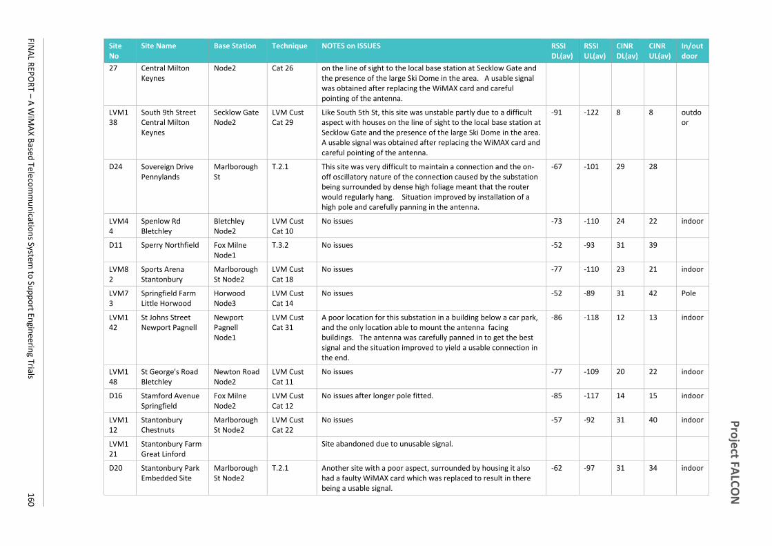
Pro
ject FA
LCO
N
FINA
L REP
OR
T – A W
iMA
X B
ased Tele
com
mu
nicatio
ns System
to Su
pp
ort En
gineerin
g Trials 1
60
Site No
Site Name Base Station Technique NOTES on ISSUES RSSI DL(av)
RSSI UL(av)
CINR DL(av)
CINR UL(av)
In/out door
27 Central Milton Keynes
Node2 Cat 26 on the line of sight to the local base station at Secklow Gate and the presence of the large Ski Dome in the area. A usable signal was obtained after replacing the WiMAX card and careful pointing of the antenna.
LVM138
South 9th Street Central Milton Keynes
Secklow Gate Node2
LVM Cust Cat 29
Like South 5th St, this site was unstable partly due to a difficult aspect with houses on the line of sight to the local base station at Secklow Gate and the presence of the large Ski Dome in the area. A usable signal was obtained after replacing the WiMAX card and careful pointing of the antenna.
-91 -122 8 8 outdoor
D24 Sovereign Drive Pennylands
Marlborough St
T.2.1 This site was very difficult to maintain a connection and the on-off oscillatory nature of the connection caused by the substation being surrounded by dense high foliage meant that the router would regularly hang. Situation improved by installation of a high pole and carefully panning in the antenna.
-67 -101 29 28
LVM44
Spenlow Rd Bletchley
Bletchley Node2
LVM Cust Cat 10
No issues -73 -110 24 22 indoor
D11 Sperry Northfield Fox Milne Node1
T.3.2 No issues -52 -93 31 39
LVM82
Sports Arena Stantonbury
Marlborough St Node2
LVM Cust Cat 18
No issues -77 -110 23 21 indoor
LVM73
Springfield Farm Little Horwood
Horwood Node3
LVM Cust Cat 14
No issues -52 -89 31 42 Pole
LVM142
St Johns Street Newport Pagnell
Newport Pagnell Node1
LVM Cust Cat 31
A poor location for this substation in a building below a car park, and the only location able to mount the antenna facing buildings. The antenna was carefully panned in to get the best signal and the situation improved to yield a usable connection in the end.
-86 -118 12 13 indoor
LVM148
St George's Road Bletchley
Newton Road Node2
LVM Cust Cat 11
No issues -77 -109 20 22 indoor
D16 Stamford Avenue Springfield
Fox Milne Node2
LVM Cust Cat 12
No issues after longer pole fitted. -85 -117 14 15 indoor
LVM112
Stantonbury Chestnuts
Marlborough St Node2
LVM Cust Cat 22
No issues -57 -92 31 40 indoor
LVM121
Stantonbury Farm Great Linford
Site abandoned due to unusable signal.
D20 Stantonbury Park Embedded Site
Marlborough St Node2
T.2.1 Another site with a poor aspect, surrounded by housing it also had a faulty WiMAX card which was replaced to result in there being a usable signal.
-62 -97 31 34 indoor
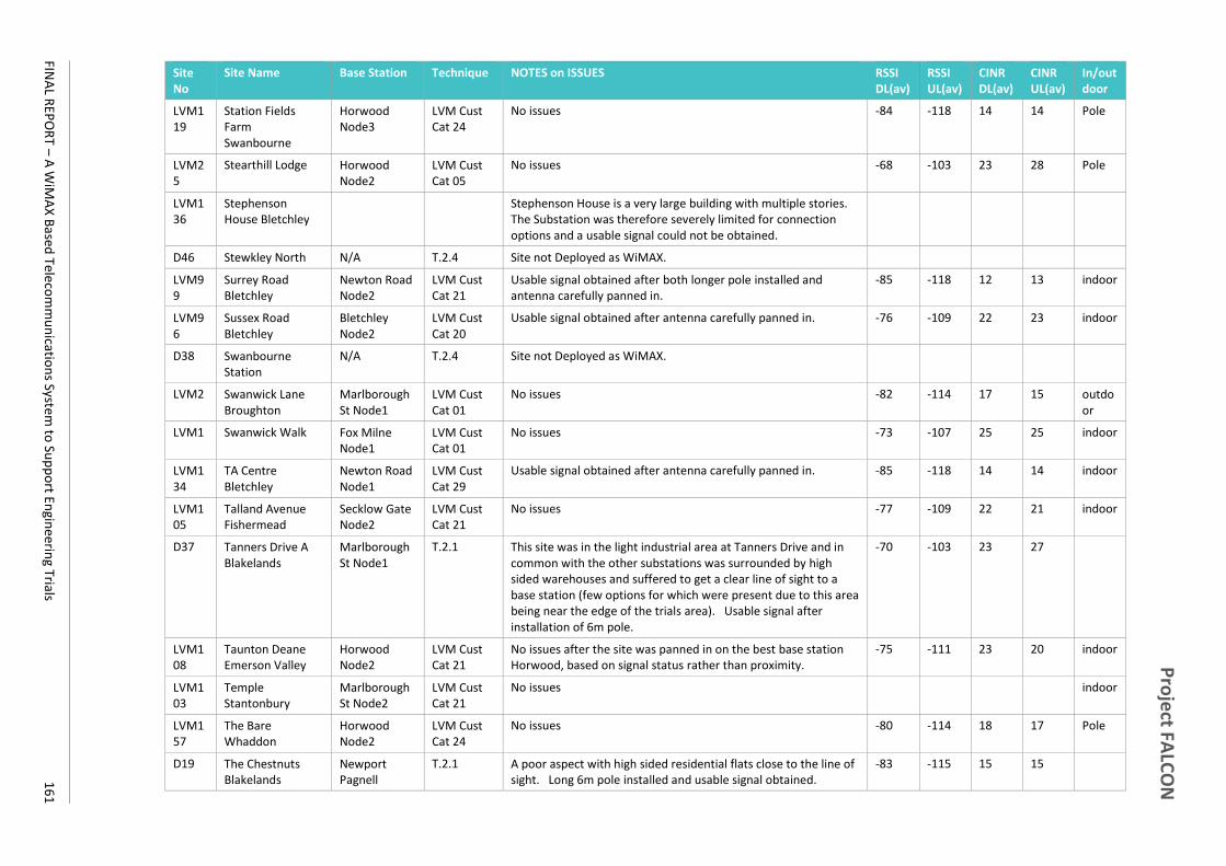
Pro
ject FA
LCO
N
FINA
L REP
OR
T – A W
iMA
X B
ased Tele
com
mu
nicatio
ns System
to Su
pp
ort En
gineerin
g Trials 1
61
Site No
Site Name Base Station Technique NOTES on ISSUES RSSI DL(av)
RSSI UL(av)
CINR DL(av)
CINR UL(av)
In/out door
LVM119
Station Fields Farm Swanbourne
Horwood Node3
LVM Cust Cat 24
No issues -84 -118 14 14 Pole
LVM25
Stearthill Lodge Horwood Node2
LVM Cust Cat 05
No issues -68 -103 23 28 Pole
LVM136
Stephenson House Bletchley
Stephenson House is a very large building with multiple stories. The Substation was therefore severely limited for connection options and a usable signal could not be obtained.
D46 Stewkley North N/A T.2.4 Site not Deployed as WiMAX.
LVM99
Surrey Road Bletchley
Newton Road Node2
LVM Cust Cat 21
Usable signal obtained after both longer pole installed and antenna carefully panned in.
-85 -118 12 13 indoor
LVM96
Sussex Road Bletchley
Bletchley Node2
LVM Cust Cat 20
Usable signal obtained after antenna carefully panned in. -76 -109 22 23 indoor
D38 Swanbourne Station
N/A T.2.4 Site not Deployed as WiMAX.
LVM2 Swanwick Lane Broughton
Marlborough St Node1
LVM Cust Cat 01
No issues -82 -114 17 15 outdoor
LVM1 Swanwick Walk Fox Milne Node1
LVM Cust Cat 01
No issues -73 -107 25 25 indoor
LVM134
TA Centre Bletchley
Newton Road Node1
LVM Cust Cat 29
Usable signal obtained after antenna carefully panned in. -85 -118 14 14 indoor
LVM105
Talland Avenue Fishermead
Secklow Gate Node2
LVM Cust Cat 21
No issues -77 -109 22 21 indoor
D37 Tanners Drive A Blakelands
Marlborough St Node1
T.2.1 This site was in the light industrial area at Tanners Drive and in common with the other substations was surrounded by high sided warehouses and suffered to get a clear line of sight to a base station (few options for which were present due to this area being near the edge of the trials area). Usable signal after installation of 6m pole.
-70 -103 23 27
LVM108
Taunton Deane Emerson Valley
Horwood Node2
LVM Cust Cat 21
No issues after the site was panned in on the best base station Horwood, based on signal status rather than proximity.
-75 -111 23 20 indoor
LVM103
Temple Stantonbury
Marlborough St Node2
LVM Cust Cat 21
No issues indoor
LVM157
The Bare Whaddon
Horwood Node2
LVM Cust Cat 24
No issues -80 -114 18 17 Pole
D19 The Chestnuts Blakelands
Newport Pagnell
T.2.1 A poor aspect with high sided residential flats close to the line of sight. Long 6m pole installed and usable signal obtained.
-83 -115 15 15

Pro
ject FA
LCO
N
FINA
L REP
OR
T – A W
iMA
X B
ased Tele
com
mu
nicatio
ns System
to Su
pp
ort En
gineerin
g Trials 1
62
Site No
Site Name Base Station Technique NOTES on ISSUES RSSI DL(av)
RSSI UL(av)
CINR DL(av)
CINR UL(av)
In/out door
Node2
LVM15
The Leys Newton Longville
Horwood Node2
LVM Cust Cat 03
No issues -64 -100 30 31 Pole
LVM38
The Linx Bletchley Bletchley Node2
LVM, T.1.4 Cust Cat 09
No issues once the antenna was panned in correctly, this site had been pointing 180 degrees off the base station bearing and picking up on the back of the antenna.
outdoor
LVM60
The Oval Oldbrook Secklow Gate Node2
LVM Cust Cat 11
No issues -82 -115 16 15 indoor
LVM118
The Stables Springfield Farm, Little Horwood
Horwood Node2
LVM Cust Cat 23
No issues -62 -97 31 34 Pole
LVM70
Thick Thorn Farm Newton Longville
Horwood Node2
LVM Cust Cat 13
No issues -75 -109 23 22 Pole
LVM57
Thorneycroft Lane Downhead Park
Marlborough St Node1
LVM, T.1.4 Cust Cat 11
This site was located such that the antenna bearing to the best base station at Marlborough St was exactly 180 degrees off the bearing to FOX Milne so both were picking up with consequent co-channel interference. Attenuation was fitted and a usable signal resulted.
-72 -103 25 26 indoor
D36 Tickford Engineering
Newport Pagnell Node2
T.2.1 No issues -64 -97 29 33
LVM90
Tower Drive Neath Hill
Marlborough St Node1
LVM Cust Cat 20
No issues -64 -96 31 32 outdoor
LVM34
Turnberry Close Bletchley
Horwood Node3
LVM Cust Cat 08
No issues after pointing to a more distant base station (Horwood) having a less obstructed Line of Sight.
-77 -111 22 20 outdoor
D09 Unisys Logistics Centre Fox Milne
Fox Milne Node1
T.3.2 No issues until a high-sided car showroom was built immediately next to the substation cutting off the line of sight to the Fox Milne Base Station. A taller pole was installed and a usable signal obtained.
-61 -98 18 35
D01 Unit 32 Blundells Road
Bradwell Abbey Node:
T.1.2, T.1.4 Some issues with intermittent connectivity, on inspection the antenna needed fin tuning to the best bearing for Bradwell Abbey and while this was through trees (which may have been why the antenna was not initially set in that direction) gave a better connection.
-74 -109 24 23 indoor
LVM5 Walton Road Middleton
Fox Milne Node1
LVM Cust Cat 01
No issues, though weak signal strength. -85 -120 14 12 indoor
LVM26
Wepener Farm Fox Milne Node2
LVM Cust Cat 05
No issues -72 -104 20 28 Pole

Pro
ject FA
LCO
N
FINA
L REP
OR
T – A W
iMA
X B
ased Tele
com
mu
nicatio
ns System
to Su
pp
ort En
gineerin
g Trials 1
63
Site No
Site Name Base Station Technique NOTES on ISSUES RSSI DL(av)
RSSI UL(av)
CINR DL(av)
CINR UL(av)
In/out door
LVM92
Westbury Lane Newport Pagnell
Newport Pagnell Node2
LVM, T.1.4 Cust Cat 20
No issues after installation of a taller 6m pole. Poor aspect location amongst housing.
-77 -111 21 19 outdoor
LVM42
Westminster Drive Bletchley
Bletchley Node2
LVM, T.1.4 Cust Cat 10
No issues -61 -93 31 39 indoor
LVM80
Whaddon Childs Way Node1
LVM Cust Cat 17
No issues -86 -118 9 10 Pole
LVM37
Whaddon Council Houses
Horwood Node1
LVM, T.1.4 Cust Cat 09
Suffered co-channel interference. Little could be done as site had a poor aspect, but remained usable as an LVM site.
-90 -125 9 8 outdoor
LVM46
Whalley Drive Bletchley Node2
LVM Cust Cat 10
No issues -63 -98 31 34 indoor
LVM78
Wheatcroft Close Beanhill
Bletchley Node1
LVM Cust Cat 16
No issues -79 -112 19 20 indoor
LVM18
Wild Farm Gt. Horwood
Horwood Node1
LVM Cust Cat 03
No issues -72 -109 25 23 Pole
D30 Willen Park Avenue Milton Keynes
Marlborough St Node1
T.2.1 No issues -74 -107 24 22
D02 Willen Road Newport Pagnell
Newport Pagnell Node1
T.1.3, Cust Cat 24
No issues -72 -105 26 27
LVM123
Willen Road Street Lighting
Newport Pagnell Node1
LVM Cust Cat 24
No issues -48 -92 31 39 Pole
LVM12
Wincanton Hill Railway Farm
LVM Cust Cat: 02
Very poor aspect, on a hill amongst housing with a new home extension under construction opposite. Abandoned due to poor signal and few alternative base station options (site on the SW edge of the trials area)
D44 Wing Road Stewkley
T.2.4 Not used.
P05 Winslow Primary Horwood Node3
T.2.4 No issues indoor
LVM122
Woad Farm Cottages Weston Underwood
LVM Cust Cat: 24
Very poor aspect, a pole site with difficult road side access and the main access point being over a ditch. Abandoned due to poor signal and few alternative base station options (site on the NE edge of the trials area)
LVM33
Worrelle Avenue Middleton
Fox Milne Node1
LVM Cust Cat 07
No issues -64 -98 31 34 indoor

Pro
ject FA
LCO
N
FINA
L REP
OR
T – A W
iMA
X B
ased Tele
com
mu
nicatio
ns System
to Su
pp
ort En
gineerin
g Trials 1
64
Site No
Site Name Base Station Technique NOTES on ISSUES RSSI DL(av)
RSSI UL(av)
CINR DL(av)
CINR UL(av)
In/out door
LVM154
Wraxall Way Ashlands
Bletchley Node1
LVM Cust Cat 01
No issues -84 -117 15 15

Project FALCON
FINAL REPORT – A WiMAX Based Telecommunications System to Support Engineering Trials 165
Project FALCON
FINAL REPORT – A WiMAX Based Telecommunications System to Support Engineering Trials 166
Western Power Distribution (East Midlands) plc
Registered in England and Wales No. 2366923
Registered Office: Avonbank, Feeder Road, Bristol BS2 0TB
Western Power Distribution (West Midlands) plc
Registered in England and Wales No. 3600574
Registered Office: Avonbank, Feeder Road, Bristol BS2 0TB
Western Power Distribution (South West) plc
Registered in England and Wales No. 2366894
Registered Office: Avonbank, Feeder Road, Bristol BS2 0TB
Western Power Distribution (South Wales) plc
Registered in Wales No. 2366985
Registered Office: Avonbank, Feeder Road, Bristol BS2 0TB