Embed Size (px)
Citation preview

1
Wellesley College CS115/PHYS115Robotic Design Studio
January , 1999
COURSE INFORMATION
Instructors: Robbie Berg (Physics), SCI554, x3110, [email protected] Turbak (Computer Science), [email protected](Franklyn is on leave this year, but he will be helping out during thefirst week or so of the course.)
Location: SCI 396. (SCI 392 is also available as a work space.)
Meeting Times: 1pm -- 4pm, Monday -- Thursday, January 4 -- 25. There is nomeeting on Martin Luther King day (Monday, January 18). Allmembers of the class are expected to participate in the RobotExhibition from 4:30 -- 6pm on Monday, January 25 and the cleanupparty immediately following (6pm -- 7:30pm).
Course Web Sites: We maintain a web site for Robotic Design Studio, containinggeneral information about the course, pictures from past years, etc.at:
http://www.wellesley.edu/Physics/robots/studio.html
There is also a web site with information pertaining specifically tothis year’s version of the course at:
http://nike.wellesley.edu/~rds/
For example, information about creating a web page for your robotcan be found at this site.
Course Overview
In this intensive introductory course, you will have an opportunity to design andassemble robots out of LEGO parts, sensors, motors, and Handy Boards (palm-sizedcomputers), and then program your creations to do your bidding. We start by learningsome fundamental robotics skills in the context of studying and modifying a simplerobot known as SciBorg. Then, working in small teams, you will design and buildyour own robot. The course culminates in a Robot Exhibition on January 25, from4:30 -- 6pm, in which you will show off your robots to the Wellesley community.This is a festive event that is attended by students, faculty, staff, and their families.
This course is rooted in constructionism, whose main tenet is that people learn bestwhen actively engaged in hands-on projects that are personally meaningful andenjoyable.
2
Robotic projects tie together aspects of a surprisingly wide range of disciplines,including computer science, physics, math, biology, psychology, engineering, and art.Here are some of the concepts and skills you can expect to learn in this course:
• Robot = sensors + controller + actuators• Simple programming: robot commands, control flow (sequencing, conditionals,loops, procedure calls, concurrency), procedural abstraction• Basic electronics: voltage, current, power, motors, sensors• Fundamental mechanics: building robust structures, friction, power transmission,gearing, LEGO design clichés• Animal and machine behavior, with ties to biological, cognitive, and social science.
More generally, by working on this design project you will also be introduced to omeof the “Big Ideas” of engineering:
• hypothesis testing and debugging• making iterative improvements• working with systems , design in multiple domains, subpart interaction• designingbehaviors; sophisticated behaviors can arise from relatively simple rules• working in the real (noisy, messy, unpredictable etc.) world• divide-and-conquer strategies for problem solving• modularity and abstraction• feedback and control• paying attention to aesthetics,• the value of simplicity and robustness
We believe that it is critical that this kind of exposure to the important ideas ofengineering be a part of today’s liberal arts education; a groundingin these ideas isnecessary in order to understand our times and our culture. The best way to becomefluent with these ideas is to become a designer and a builder. In today’s liberal artscurriculum there is a relative absence of design and building for students of science ortechnology. (In contrast, there tend to be lots of design experiences for artists andhumanities students.)
Prerequisites
The only prerequisite for this course is a willingness to learn about, and have funwith, robots. The course is not just for scientists --- all creative people are encouragedto participate!
Credit
One-half (0.5) units of credit will be awarded for successful completion of thiscourse. This credit counts toward the Natural and Physical Sciences (NPS)distribution.

3
Reading Materials
We will hand out several articles, manuals, and notes during the course, and will postsuggested reading where appropriate.
Homework
In addition to design challenges and other hands-on activities in during class time,you will be asked to complete several homework assignments. Assignments willtypically involve reflecting and expanding on work done in class, thinking aboutpoints raised in reading, or documenting stages in the design and construction of yourrobot.
Individual Design Journal
Each student is required to maintain an individual design journal to document herjourney through the course. The design journal is a single artifact that should containall of the following:
• Lecture notes taking during class.• Answers to homework assignments.• Documentation of your solutions to the design challenges, including sketches, code,and explanation of strategies.• Documentation detailing the design and construction of your final project, includingwords, sketches, and code.• Other thoughts/observations/sketches inspired by the hands-on activities, reading,etc.
We encourage you use a bound notebook such as a composition notebook or a spiralnotebook for your design journal. We recommend that you do not use a loose-leafbinder for your design notebook. You should date each entry to the journal, and tapeor glue loose materials (such as code listings) to pages in the journal.
Group Robot Project
The second half of the course is devoted to the robot project, in which you will workin a team of two or three people to design, build, exhibit, and document a robot. Theproject is open-ended; you should brainstorm with your teammates about projects thatare fun, exciting, and challenging, but at the same time realistic. To give you a senseof what's possible, you should browse the following web pages:
http://www.wellesley.edu/Physics/robots/web-pages-98.html(Descriptions of the 1998 robot projects.)
http://www.wellesley.edu/Physics/robots/gallery.html(Descriptions of the 1996-7 robot projects.)
When forming teams for your project, it is wise to choose teammates withcomplementary strengths. For example, it's good to have members with programmingexperience, mechanical know-how, artistic sense, and good writing and presentationskills.
4
As part of your robot project, you will be expected to do the following:
As a group:
• Develop a preliminary design for your robot, including sketches and descriptionsof behavior.• Build the robot you have designed. This is an iterative process in which you willbuild, program, test, see what works and what doesn't, and make changes to thedesign. You repeat this process until you are done (rare) or you run out of time(more likely).• Document your robot with pictures, text, and code in a World-Wide Web pagethat will forever remain a part of the Robotic Design Studio electronic museum.• Exhibit the robot you have built at the Robot Exhibition on January 25, 1999.
As an individual:
• Document the design and implementation of the robot in your design journal.
Grades
Rather than focusing on a grade, we hope that you will focus on learning a lot andhaving fun while building creative robots. After all, students during two previousWinterSessions (‘96 and ‘97) builtvery impressive projects without receiving anycredit at all!
Your grade for the course will be determined by three factors:
1. Your design journal, which includes your homework assignments and yourindividual documentation for your group final project.
2. Your group robot project, particularly the web page documenting your robot.
3. Your class preparedness and participation. It is expected that you will attend allclasses (although we understand that travel plans may prevent some students fromattending the first day of class).
Grading will be fairly lenient; conscientious participation in the course is likely toearn a grade between an A and a B.
Collaboration Policy
We strongly encourage you to get to know all of your classmates and to collaborateextensively with them. Because of the interdisciplinary nature of the course, it islikely that you will be strong in some areas but weak in others. Please share yourstrengths with others, and don't hesitate to ask others for help in the areas in whichyou feel that you are weak.
In your design journal, all observations, reflections, and documentation should be inyour own words. You may reference the ideas of your classmates, but should givethem proper attribution in your writing.
5
Laboratory and Computing Environment
Classes will be held in Science Center room 396 and the adjoining room 392. Thesewill collectively be referred to as the "WinterSession Robotics Laboratory". Inaddition to class times, we will try to keep the labs open at other times to encourageplaying with the robots and working on your projects.
The lab is equipped with 10 Gateway PC computers. If you have a PC laptop you canuse it for this class if you like. We will primarily use three software applicationsduring the course:
• Handy Logo and Cricket Logo -- program development environments for theHandy Boards and Crickets• Claris Home Page -- a web-page builder• Winsock-FTP -- a file transfer program for uploading files to and downloadingfiles from the net.
Each student will be given a computer account on the Nike file server where sheshould store her personal work at the end of each class day. Details on accessingNike via Winsock-FTP will be provided. Students are also encouraged to makebackups of their work onto floppy disks.

6
Course Schedule
There are twelve three-hour class meetings, which naturally split into two categories:
1. During the first six class meetings, we will teach you the basics of robot design.These meetings will consist of brief lectures interleaved with numerous hands-onactivities in which you will modify an existing robot or build a simple robot fromscratch.
2. During the last six class meetings, you will work with your teammates on thedesign and implementation of your robot.
Below is a tentative schedule for the class:
Monday, January 4 (Class 1) Introduction to Robotic Design• What is a robot? Sensors, actuators, and controllers.• Introduction to the Handy Board, a palm-sized computer for robot controllers;
executing simple commands and downloading programs.• Build-Your-Own kinetic sculpture• Course Administrivia• Introduction to SciBorg, a pedagogical robot.• Challenge: How does SciBorg follow a line?
Tuesday , January 5 (Class 2) Robot Programming• Introduction to Handy Logo, a programming language for the Handy Board:
actuator & sensor primitives; control flow (sequencing, conditionals, loops);procedural abstraction.
• Design challenges -- program SciBorg to do the following:1) ping-pong "bounce" back and forth between walls using front and rear touch
sensors2) escape: escape from barricaded surroundings3) sobriety-test - improve SciBorg line-following behavior by minimizing constant
weaving on relatively straight portions of track.4) light follower - get SciBorg to “home in” on a bright light source• Saving work to Nike account.
Wednesday, January 6 (Class 3) LEGO Mechanical Design• Overview of LEGO Technic components• Idioms for robust LEGO construction• Power transmission: motors, gear trains, speed vs. torque trade-off, friction, worm
gears, differential gears• Design challenge: build a sturdy LEGO box that can survive a fall• Design challenge: build a single motor racing vehicle. The vehicle will participate
in a 3 meter race carrying the Handy Board and a 0.5 kg mass.
Thursday, January 7 (Class 4) Iterative Design, Crickets,• Testing and improving your designs, pre-race trials• Introduction to the Cricket, Handy Board's smaller cousin.• Cricket examples: dancing crickets, spider, scientific instrumentation• Design Challenge: Communicating Crickets• Gourmet snack

7
Friday, January 8 (No Class)• Although there is no class today, we will try to keep the lab open so that interested
students can play. Watch for details.
Monday, January 11 (Class 5) Vehicle Races, Sensors• Vehicle races• Analog and digital sensors• Standard sensor configuration; simple electronics• Detailed description of how reflectance sensor works• Demonstration of various sensors.• Sensor Assignments:
(1) find 10 different kinds of sensors in your environment (dorm, classrooms,science center, campus, etc.(2) find an interesting animal sensor and write a couple of paragraphs aboutwhat it's used for and how it works.
Tuesday, January 12 (Class 6) Advanced Robot Programming , Robot Project• Concurrency: launching processes, when demons, stopping processes, process
families• Design challenge: decomposing behaviors using concurrency.• Revisiting earlier robot designs with concurrency in mind• Shaft encoder/multitasking example• Robot project overview. Show and tell: robots from previous years.• Pick teammates for final project• Groups begin brainstorming about robot project.
Wednesday, January 13 (Class 7) Design Session• Robot project brainstorming• Work on preliminary robot project design: descriptions of behavior, sketches• LEGO Mindstorms demonstration• Video festival: Robo-Pong, The Way Things Go and more!
Thursday, January 14 (Class 8) Design Presentation• Present preliminary design to class for feedback.• Begin implementation of robot projects.
Friday , January 15 (No Class)• Although there is no class today, we will try to keep the lab open so that interested
students can work on their robots. Watch for details.
Monday , January 18 (No Class: MLK Birthday)• Although there is no class today, we will try to keep the lab open so that interested
students can work on their robots. Watch for details.
Tuesday, January 19 (Class 9) Robot Implementation• Groups continue to implement and document robots.• Tutorial on using Claris Home Page to create final project web pages.• Submit design journals for feedback on project
Wednesday, January 20 (Class 10) Robot Implementation• Groups continue to implement and document robots.• Tutorial on incorporating pictures and video into your robot project web pages.

8
Thursday, January 21 (Class 11) In-Class Exhibit• Groups present working robots in preliminary in-class exhibit to get feedback.• Robot implementation and documentation continues.• Submit draft of web page for feedback
Friday, January 22 (No Class)• Although there is no class today, we will try to keep the lab open so that interested
students can continue to work on and fine tune their robots. Watch for details.
Monday, January 25 (Class 12)• Individual notebooks and group robot web pages due today.• Testing robots in the exhibit space (Sage Lounge, 2nd floor of Science Center)• Last-minute modifications to robots.• Robot Exhibition: 4:30--6pm in the Sage Lounge.• Cleanup Party: 6pm--7:30pm

Getting Started WithHandy Boards and Handy Logo
by
Robbie BergDepartment of Physics
and
Franklyn TurbakDepartment of Computer Science
Wellesley College
The Handy Board and Handy Logo were developed by members of theEpistemology and Learning Group at the MIT Media Lab as part of theProgrammable Bricks project. For more information please see
http://lcs.www.media.mit.edu/groups/el/elprojects.html
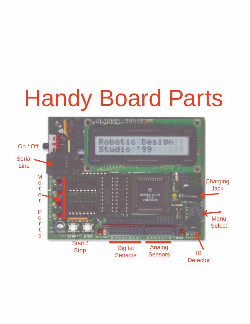
Analog Sensors
Digital Sensors
Start / Stop
Motor Ports
On / Off
Menu Select
Charging Jack
Serial Line
Handy Board Parts
IRDetector
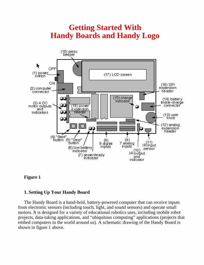
Getting Started WithHandy Boards and Handy Logo
Figure 1
1. Setting Up Your Handy Board
The Handy Board is a hand-held, battery-powered computer that can receive inputsfrom electronic sensors (including touch, light, and sound sensors) and operate smallmotors. It is designed for a variety of educational robotics uses, including mobile robotprojects, data-taking applications, and “ubiquitous computing” applications (projects thatembed computers in the world around us). A schematic drawing of the Handy Board isshown in figure 1 above.
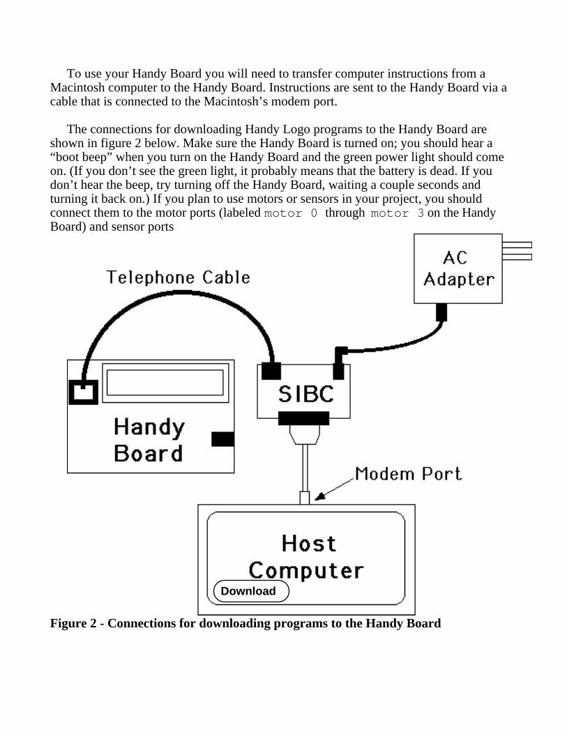
To use your Handy Board you will need to transfer computer instructions from aMacintosh computer to the Handy Board. Instructions are sent to the Handy Board via acable that is connected to the Macintosh’s modem port.
The connections for downloading Handy Logo programs to the Handy Board areshown in figure 2 below. Make sure the Handy Board is turned on; you should hear a“boot beep” when you turn on the Handy Board and the green power light should comeon. (If you don’t see the green light, it probably means that the battery is dead. If youdon’t hear the beep, try turning off the Handy Board, waiting a couple seconds andturning it back on.) If you plan to use motors or sensors in your project, you shouldconnect them to the motor ports (labeled motor 0 through motor 3 on the HandyBoard) and sensor ports
Download
Figure 2 - Connections for downloading programs to the Handy Board
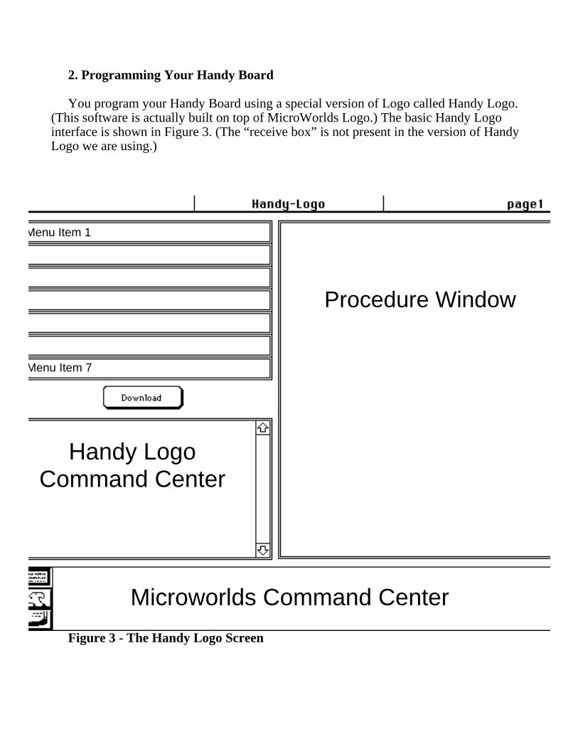
2. Programming Your Handy Board
You program your Handy Board using a special version of Logo called Handy Logo.(This software is actually built on top of MicroWorlds Logo.) The basic Handy Logointerface is shown in Figure 3. (The “receive box” is not present in the version of HandyLogo we are using.)
Procedure Window
Menu Item 1
Menu Item 7
Handy LogoCommand Center
Microworlds Command Center
Figure 3 - The Handy Logo Screen
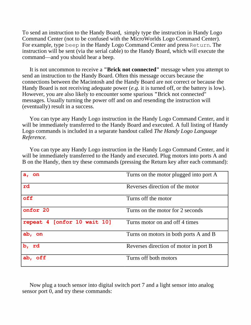
To send an instruction to the Handy Board, simply type the instruction in Handy LogoCommand Center (not to be confused with the MicroWorlds Logo Command Center).For example, type beep in the Handy Logo Command Center and press Return. Theinstruction will be sent (via the serial cable) to the Handy Board, which will execute thecommand—and you should hear a beep.
It is not uncommon to receive a "Brick not connected" message when you attempt tosend an instruction to the Handy Board. Often this message occurs because theconnections between the Macintosh and the Handy Board are not correct or because theHandy Board is not receiving adequate power (e.g. it is turned off, or the battery is low).However, you are also likely to encounter some spurious "Brick not connected"messages. Usually turning the power off and on and resending the instruction will(eventually) result in a success.
You can type any Handy Logo instruction in the Handy Logo Command Center, and itwill be immediately transferred to the Handy Board and executed. A full listing of HandyLogo commands is included in a separate handout called The Handy Logo LanguageReference.
You can type any Handy Logo instruction in the Handy Logo Command Center, and itwill be immediately transferred to the Handy and executed. Plug motors into ports A andB on the Handy, then try these commands (pressing the Return key after each command):
a, on Turns on the motor plugged into port A
rd Reverses direction of the motor
off Turns off the motor
onfor 20 Turns on the motor for 2 seconds
repeat 4 [onfor 10 wait 10] Turns motor on and off 4 times
ab, on Turns on motors in both ports A and B
b, rd Reverses direction of motor in port B
ab, off Turns off both motors
Now plug a touch sensor into digital switch port 7 and a light sensor into analogsensor port 0, and try these commands:
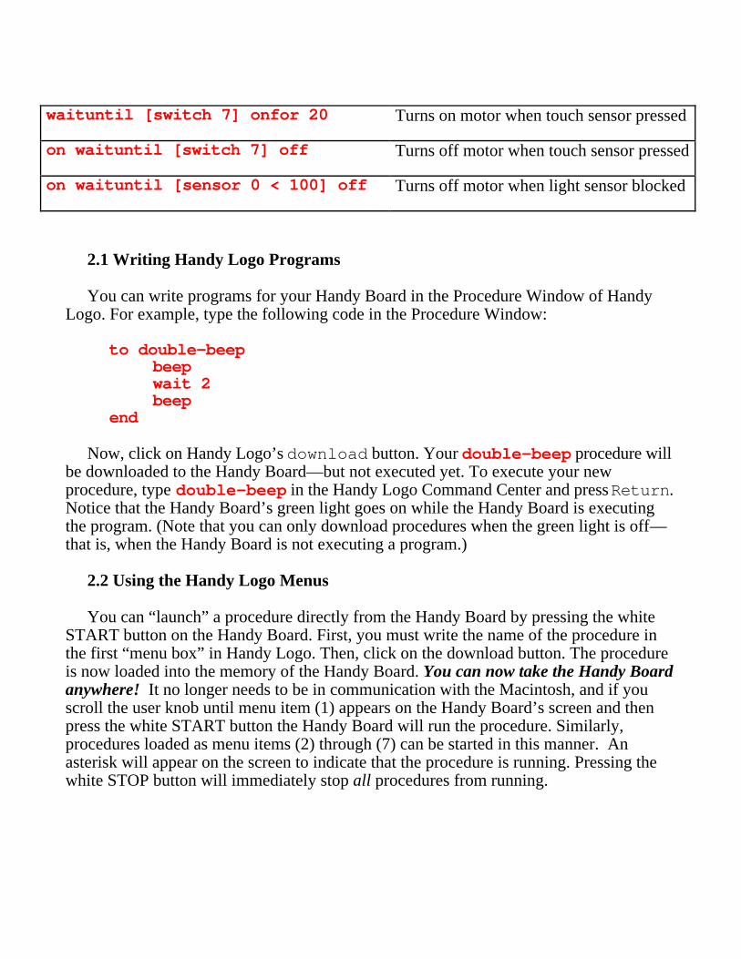
waituntil [switch 7] onfor 20 Turns on motor when touch sensor pressed
on waituntil [switch 7] off Turns off motor when touch sensor pressed
on waituntil [sensor 0 < 100] off Turns off motor when light sensor blocked
2.1 Writing Handy Logo Programs
You can write programs for your Handy Board in the Procedure Window of HandyLogo. For example, type the following code in the Procedure Window:
to double-beepbeepwait 2beep
end
Now, click on Handy Logo’s download button. Your double-beep procedure willbe downloaded to the Handy Board—but not executed yet. To execute your newprocedure, type double-beep in the Handy Logo Command Center and press Return.Notice that the Handy Board’s green light goes on while the Handy Board is executingthe program. (Note that you can only download procedures when the green light is off—that is, when the Handy Board is not executing a program.)
2.2 Using the Handy Logo Menus
You can “launch” a procedure directly from the Handy Board by pressing the whiteSTART button on the Handy Board. First, you must write the name of the procedure inthe first “menu box” in Handy Logo. Then, click on the download button. The procedureis now loaded into the memory of the Handy Board. You can now take the Handy Boardanywhere! It no longer needs to be in communication with the Macintosh, and if youscroll the user knob until menu item (1) appears on the Handy Board’s screen and thenpress the white START button the Handy Board will run the procedure. Similarly,procedures loaded as menu items (2) through (7) can be started in this manner. Anasterisk will appear on the screen to indicate that the procedure is running. Pressing thewhite STOP button will immediately stop all procedures from running.
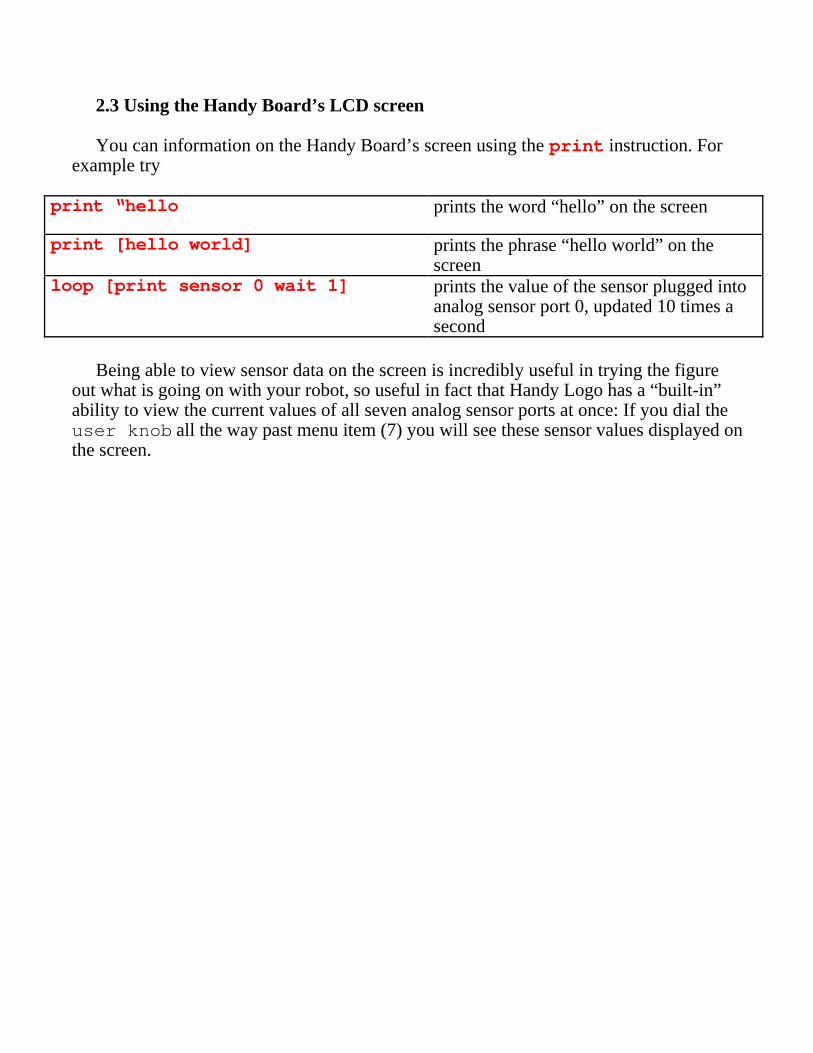
2.3 Using the Handy Board’s LCD screen
You can information on the Handy Board’s screen using the print instruction. Forexample try
print “hello prints the word “hello” on the screen
print [hello world] prints the phrase “hello world” on thescreen
loop [print sensor 0 wait 1] prints the value of the sensor plugged intoanalog sensor port 0, updated 10 times asecond
Being able to view sensor data on the screen is incredibly useful in trying the figureout what is going on with your robot, so useful in fact that Handy Logo has a “built-in”ability to view the current values of all seven analog sensor ports at once: If you dial theuser knob all the way past menu item (7) you will see these sensor values displayed onthe screen.
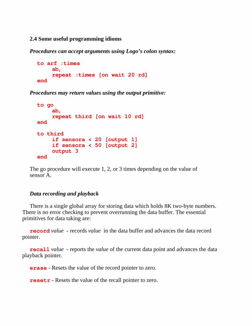
2.4 Some useful programming idioms
Procedures can accept arguments using Logo’s colon syntax:
to arf :timesab,repeat :times [on wait 20 rd]
end
Procedures may return values using the output primitive:
to goab,repeat third [on wait 10 rd]
end
to thirdif sensora < 20 [output 1]if sensora < 50 [output 2]output 3
end
The go procedure will execute 1, 2, or 3 times depending on the value ofsensor A.
Data recording and playback
There is a single global array for storing data which holds 8K two-byte numbers.There is no error checking to prevent overrunning the data buffer. The essentialprimitives for data taking are:
record value - records value in the data buffer and advances the data recordpointer.
recall value - reports the value of the current data point and advances the dataplayback pointer.
erase - Resets the value of the record pointer to zero.
resetr - Resets the value of the recall pointer to zero.
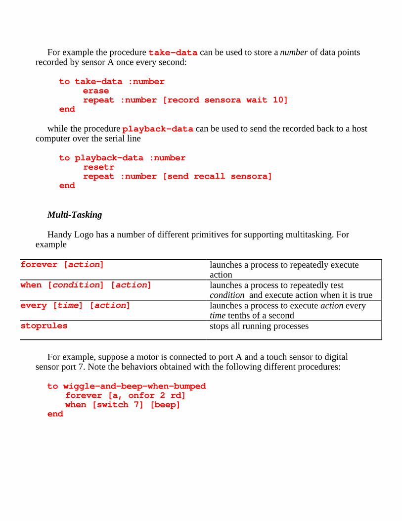
For example the procedure take-data can be used to store a number of data pointsrecorded by sensor A once every second:
to take-data :numbereraserepeat :number [record sensora wait 10]
end
while the procedure playback-data can be used to send the recorded back to a hostcomputer over the serial line
to playback-data :numberresetrrepeat :number [send recall sensora]
end
Multi-Tasking
Handy Logo has a number of different primitives for supporting multitasking. Forexample
forever [action] launches a process to repeatedly executeaction
when [condition] [action] launches a process to repeatedly testcondition and execute action when it is true
every [time] [action] launches a process to execute action everytime tenths of a second
stoprules stops all running processes
For example, suppose a motor is connected to port A and a touch sensor to digitalsensor port 7. Note the behaviors obtained with the following different procedures:
to wiggle-and-beep-when-bumpedforever [a, onfor 2 rd]when [switch 7] [beep]
end
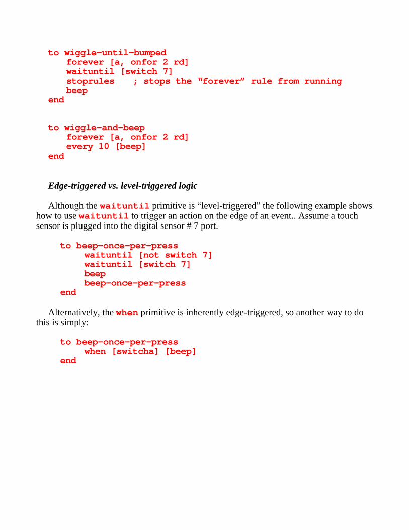
to wiggle-until-bumpedforever [a, onfor 2 rd]waituntil [switch 7]stoprules ; stops the “forever” rule from runningbeep
end
to wiggle-and-beepforever [a, onfor 2 rd]every 10 [beep]
end
Edge-triggered vs. level-triggered logic
Although the waituntil primitive is “level-triggered” the following example showshow to use waituntil to trigger an action on the edge of an event.. Assume a touchsensor is plugged into the digital sensor # 7 port.
to beep-once-per-presswaituntil [not switch 7]waituntil [switch 7]beepbeep-once-per-press
end
Alternatively, the when primitive is inherently edge-triggered, so another way to dothis is simply:
to beep-once-per-presswhen [switcha] [beep]
end
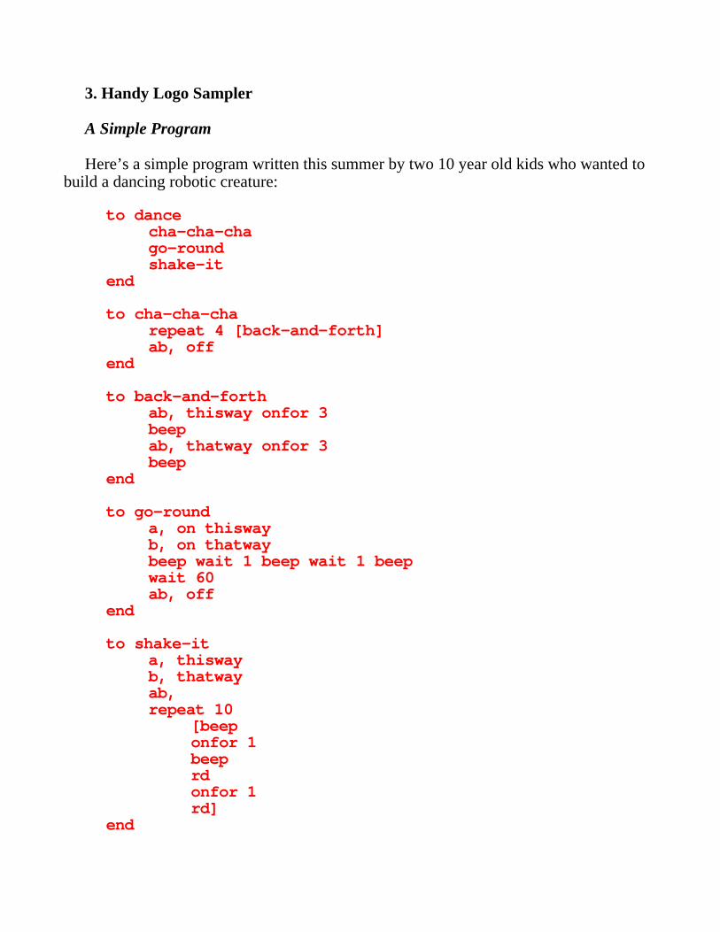
3. Handy Logo Sampler
A Simple Program
Here’s a simple program written this summer by two 10 year old kids who wanted tobuild a dancing robotic creature:
to dancecha-cha-chago-roundshake-it
end
to cha-cha-charepeat 4 [back-and-forth]ab, off
end
to back-and-forthab, thisway onfor 3beepab, thatway onfor 3beep
end
to go-rounda, on thiswayb, on thatwaybeep wait 1 beep wait 1 beepwait 60ab, off
end
to shake-ita, thiswayb, thatwayab,repeat 10
[beeponfor 1beeprdonfor 1rd]
end
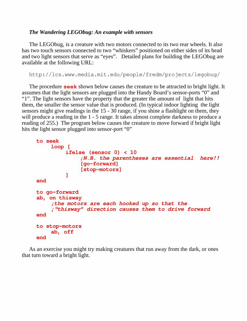
The Wandering LEGObug: An example with sensors
The LEGObug, is a creature with two motors connected to its two rear wheels. It alsohas two touch sensors connected to two “whiskers” positioned on either sides of its headand two light sensors that serve as “eyes”. Detailed plans for building the LEGObug areavailable at the following URL:
http://lcs.www.media.mit.edu/people/fredm/projects/legobug/
The procedure seek shown below causes the creature to be attracted to bright light. Itassumes that the light sensors are plugged into the Handy Board’s sensor-ports “0” and“1”. The light sensors have the property that the greater the amount of light that hitsthem, the smaller the sensor value that is produced. (In typical indoor lighting the lightsensors might give readings in the 15 - 30 range, if you shine a flashlight on them, theywill produce a reading in the 1 - 5 range. It takes almost complete darkness to produce areading of 255.) The program below causes the creature to move forward if bright lighthits the light sensor plugged into sensor-port “0”
to seekloop [
ifelse (sensor 0) < 10;N.B. the parentheses are essential here!![go-forward][stop-motors]
]end
to go-forwardab, on thisway
;the motors are each hooked up so that the ;“thisway” direction causes them to drive forward
end
to stop-motorsab, off
end
As an exercise you might try making creatures that run away from the dark, or onesthat turn toward a bright light.
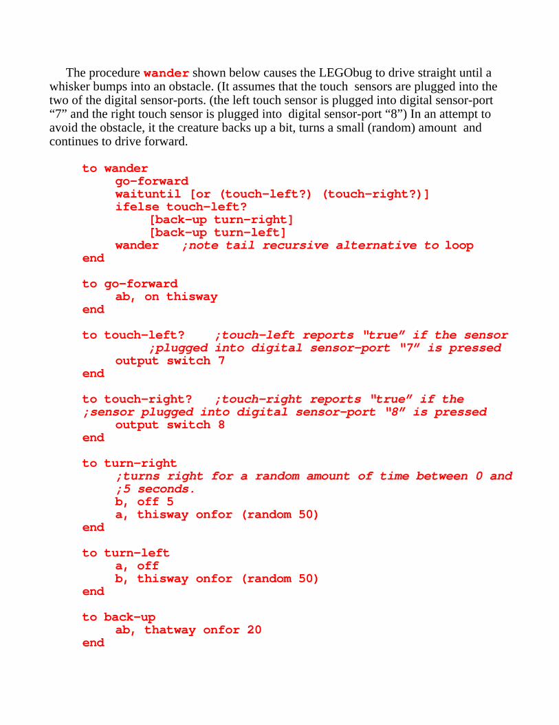
The procedure wander shown below causes the LEGObug to drive straight until awhisker bumps into an obstacle. (It assumes that the touch sensors are plugged into thetwo of the digital sensor-ports. (the left touch sensor is plugged into digital sensor-port“7” and the right touch sensor is plugged into digital sensor-port “8”) In an attempt toavoid the obstacle, it the creature backs up a bit, turns a small (random) amount andcontinues to drive forward.
to wandergo-forwardwaituntil [or (touch-left?) (touch-right?)]ifelse touch-left?
[back-up turn-right][back-up turn-left]
wander ;note tail recursive alternative to loopend
to go-forwardab, on thisway
end
to touch-left? ;touch-left reports “true” if the sensor;plugged into digital sensor-port “7” is pressed
output switch 7end
to touch-right? ;touch-right reports “true” if the;sensor plugged into digital sensor-port “8” is pressed
output switch 8end
to turn-right;turns right for a random amount of time between 0 and;5 seconds.b, off 5a, thisway onfor (random 50)
end
to turn-lefta, offb, thisway onfor (random 50)
end
to back-upab, thatway onfor 20
end
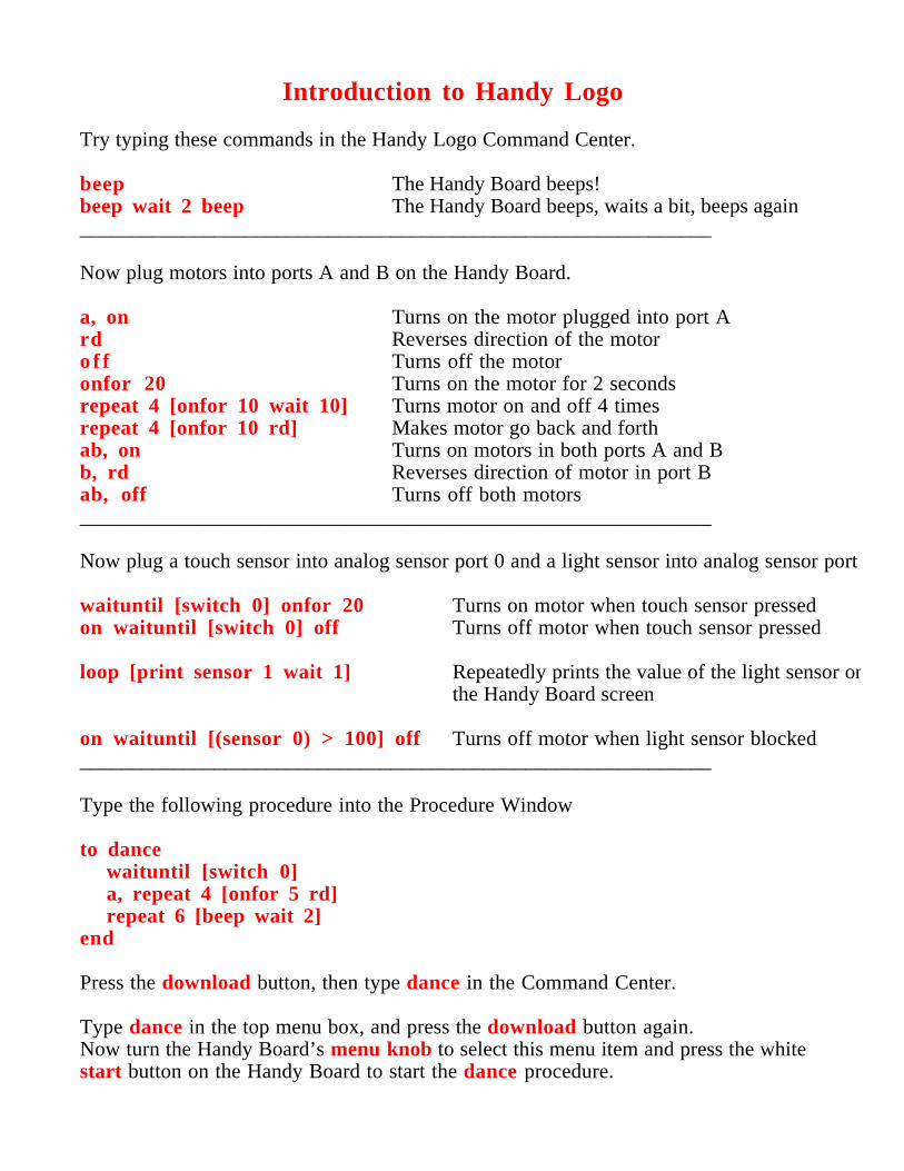
Introduction to Handy Logo
Try typing these commands in the Handy Logo Command Center.
beep The Handy Board beeps!beep wait 2 beep The Handy Board beeps, waits a bit, beeps again_____________________________________________________________
Now plug motors into ports A and B on the Handy Board.
a, on Turns on the motor plugged into port Ard Reverses direction of the motoro f f Turns off the motoronfor 20 Turns on the motor for 2 secondsrepeat 4 [onfor 10 wait 10] Turns motor on and off 4 timesrepeat 4 [onfor 10 rd] Makes motor go back and forthab, on Turns on motors in both ports A and Bb, rd Reverses direction of motor in port Bab, off Turns off both motors_____________________________________________________________
Now plug a touch sensor into analog sensor port 0 and a light sensor into analog sensor port
waituntil [switch 0] onfor 20 Turns on motor when touch sensor pressedon waituntil [switch 0] off Turns off motor when touch sensor pressed
loop [print sensor 1 wait 1] Repeatedly prints the value of the light sensor onthe Handy Board screen
on waituntil [(sensor 0) > 100] off Turns off motor when light sensor blocked_____________________________________________________________
Type the following procedure into the Procedure Window
to dancewaituntil [switch 0]a, repeat 4 [onfor 5 rd]repeat 6 [beep wait 2]
end
Press the download button, then type dance in the Command Center.
Type dance in the top menu box, and press the download button again.Now turn the Handy Board’s menu knob to select this menu item and press the whitestart button on the Handy Board to start the dance procedure.
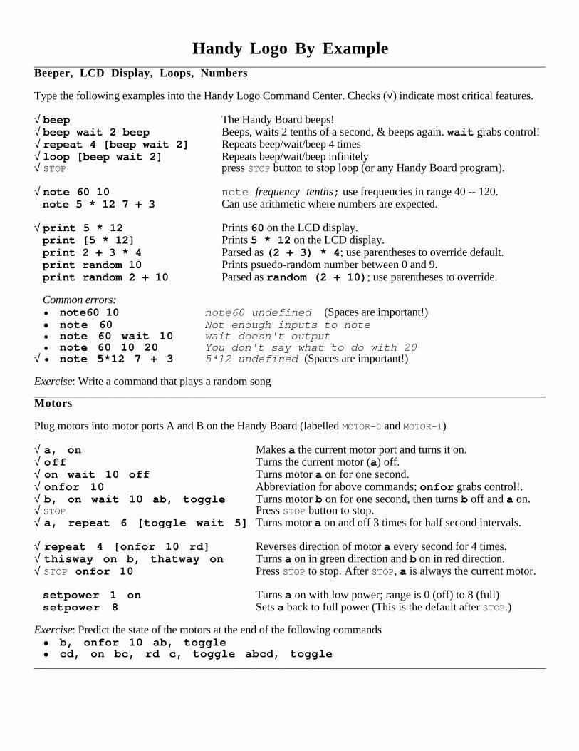
Handy Logo By Example__________________________________________________________________________________________Beeper, LCD Display, Loops, Numbers
Type the following examples into the Handy Logo Command Center. Checks (√) indicate most critical features.
√ beep The Handy Board beeps!√ beep wait 2 beep Beeps, waits 2 tenths of a second, & beeps again. wait grabs control!√ repeat 4 [beep wait 2] Repeats beep/wait/beep 4 times√ loop [beep wait 2] Repeats beep/wait/beep infinitely√ STOP press STOP button to stop loop (or any Handy Board program).
√ note 60 10 note frequency tenths; use frequencies in range 40 -- 120.note 5 * 12 7 + 3 Can use arithmetic where numbers are expected.
√ print 5 * 12 Prints 60 on the LCD display.print [5 * 12] Prints 5 * 12 on the LCD display.print 2 + 3 * 4 Parsed as (2 + 3) * 4 ; use parentheses to override default.print random 10 Prints psuedo-random number between 0 and 9.print random 2 + 10 Parsed as random (2 + 10) ; use parentheses to override.
Common errors:• note60 10 note60 undefined (Spaces are important!)• note 60 Not enough inputs to note• note 60 wait 10 wait doesn't output• note 60 10 20 You don't say what to do with 20
√ • note 5*12 7 + 3 5*12 undefined (Spaces are important!)
Exercise: Write a command that plays a random song__________________________________________________________________________________________Motors
Plug motors into motor ports A and B on the Handy Board (labelled MOTOR-0 and MOTOR-1)
√ a, on Makes a the current motor port and turns it on.√ off Turns the current motor (a) off.√ on wait 10 off Turns motor a on for one second.√ onfor 10 Abbreviation for above commands; onfor grabs control!.√ b, on wait 10 ab, toggle Turns motor b on for one second, then turns b off and a on.√ STOP Press STOP button to stop.√ a, repeat 6 [toggle wait 5] Turns motor a on and off 3 times for half second intervals.
√ repeat 4 [onfor 10 rd] Reverses direction of motor a every second for 4 times.√ thisway on b, thatway on Turns a on in green direction and b on in red direction.√ STOP onfor 10 Press STOP to stop. After STOP, a is always the current motor.
setpower 1 on Turns a on with low power; range is 0 (off) to 8 (full)setpower 8 Sets a back to full power (This is the default after STOP.)
Exercise: Predict the state of the motors at the end of the following commands• b, onfor 10 ab, toggle• cd, on bc, rd c, toggle abcd, toggle
__________________________________________________________________________________________
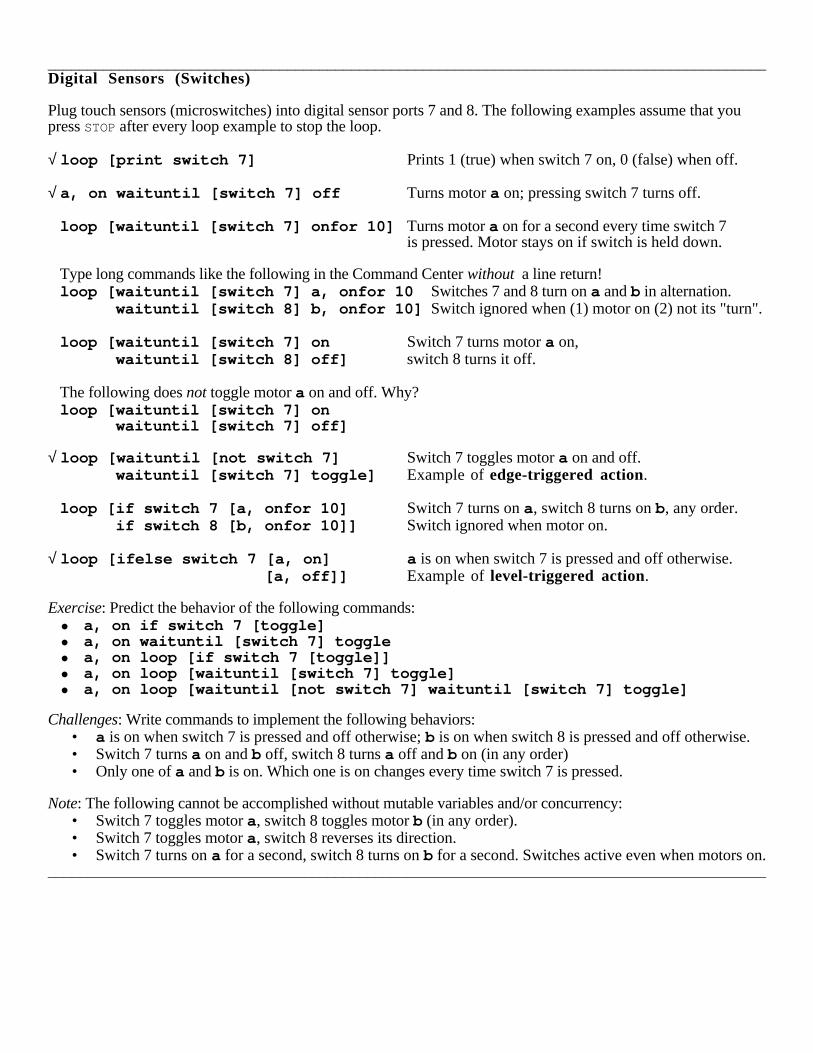
__________________________________________________________________________________________Digital Sensors (Switches)
Plug touch sensors (microswitches) into digital sensor ports 7 and 8. The following examples assume that youpress STOP after every loop example to stop the loop.
√ loop [print switch 7] Prints 1 (true) when switch 7 on, 0 (false) when off.
√ a, on waituntil [switch 7] off Turns motor a on; pressing switch 7 turns off.
loop [waituntil [switch 7] onfor 10] Turns motor a on for a second every time switch 7 is pressed. Motor stays on if switch is held down.
Type long commands like the following in the Command Center without a line return!loop [waituntil [switch 7] a, onfor 10 Switches 7 and 8 turn on a and b in alternation. waituntil [switch 8] b, onfor 10] Switch ignored when (1) motor on (2) not its "turn".
loop [waituntil [switch 7] on Switch 7 turns motor a on, waituntil [switch 8] off] switch 8 turns it off.
The following does not toggle motor a on and off. Why?loop [waituntil [switch 7] on waituntil [switch 7] off]
√ loop [waituntil [not switch 7] Switch 7 toggles motor a on and off. waituntil [switch 7] toggle] Example of edge-triggered action.
loop [if switch 7 [a, onfor 10] Switch 7 turns on a, switch 8 turns on b, any order. if switch 8 [b, onfor 10]] Switch ignored when motor on.
√ loop [ifelse switch 7 [a, on] a is on when switch 7 is pressed and off otherwise. [a, off]] Example of level-triggered action.
Exercise: Predict the behavior of the following commands:• a, on if switch 7 [toggle]• a, on waituntil [switch 7] toggle• a, on loop [if switch 7 [toggle]]• a, on loop [waituntil [switch 7] toggle]• a, on loop [waituntil [not switch 7] waituntil [switch 7] toggle]
Challenges: Write commands to implement the following behaviors:• a is on when switch 7 is pressed and off otherwise; b is on when switch 8 is pressed and off otherwise.• Switch 7 turns a on and b off, switch 8 turns a off and b on (in any order)• Only one of a and b is on. Which one is on changes every time switch 7 is pressed.
Note: The following cannot be accomplished without mutable variables and/or concurrency:• Switch 7 toggles motor a, switch 8 toggles motor b (in any order).• Switch 7 toggles motor a, switch 8 reverses its direction.• Switch 7 turns on a for a second, switch 8 turns on b for a second. Switches active even when motors on.
__________________________________________________________________________________________
__________________________________________________________________________________________Analog Sensors
Plug light sensor into analog sensor ports 0. The following examples assume that you press STOP after every loopexample to stop the loop.
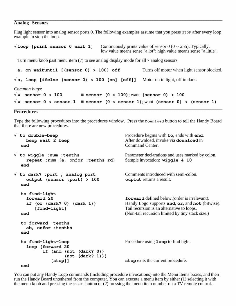
√ loop [print sensor 0 wait 1] Continuously prints value of sensor 0 (0 -- 255). Typically,low value means sense "a lot"; high value means sense "a little".
Turn menu knob past menu item (7) to see analog display mode for all 7 analog sensors.
a, on waituntil [(sensor 0) > 100] off Turns off motor when light sensor blocked.
√ a, loop [ifelse (sensor 0) < 100 [on] [off]] Motor on in light, off in dark.
Common bugs:√ • sensor 0 < 100 ≡ sensor (0 < 100) ; want (sensor 0) < 100
√ • sensor 0 < sensor 1 ≡ sensor (0 < sensor 1) ; want (sensor 0) < (sensor 1)__________________________________________________________________________________________Procedures
Type the following procedures into the procedures window. Press the Download button to tell the Handy Boardthat there are new procedures.
√ to double-beep Procedure begins with to , ends with end . beep wait 2 beep After download, invoke via download inend Command Center.
√ to wiggle :num :tenths Parameter declarations and uses marked by colon. repeat :num [a, onfor :tenths rd] Sample invocation: wiggle 4 10end
√ to dark? :port ; analog port Comments introduced with semi-colon. output (sensor :port) > 100 ouptut returns a result.end
to find-light forward 20 forward defined below.(order is irrelevant). if (or (dark? 0) (dark 1)) Handy Logo supports and , or , and not (bitwise). [find-light] Tail recursion is an alternative to loops.end (Non-tail recursion limited by tiny stack size.)
to forward :tenths ab, onfor :tenthsend
to find-light-loop Procedure using loop to find light. loop [forward 20 if (and (not (dark? 0)) (not (dark? 1))) [stop]] stop exits the current procedure.end
You can put any Handy Logo commands (including procedure invocations) into the Menu Items boxes, and thenrun the Handy Board untethered from the computer. You can execute a menu item by either (1) selecting it withthe menu knob and pressing the START button or (2) pressing the menu item number on a TV remote control.
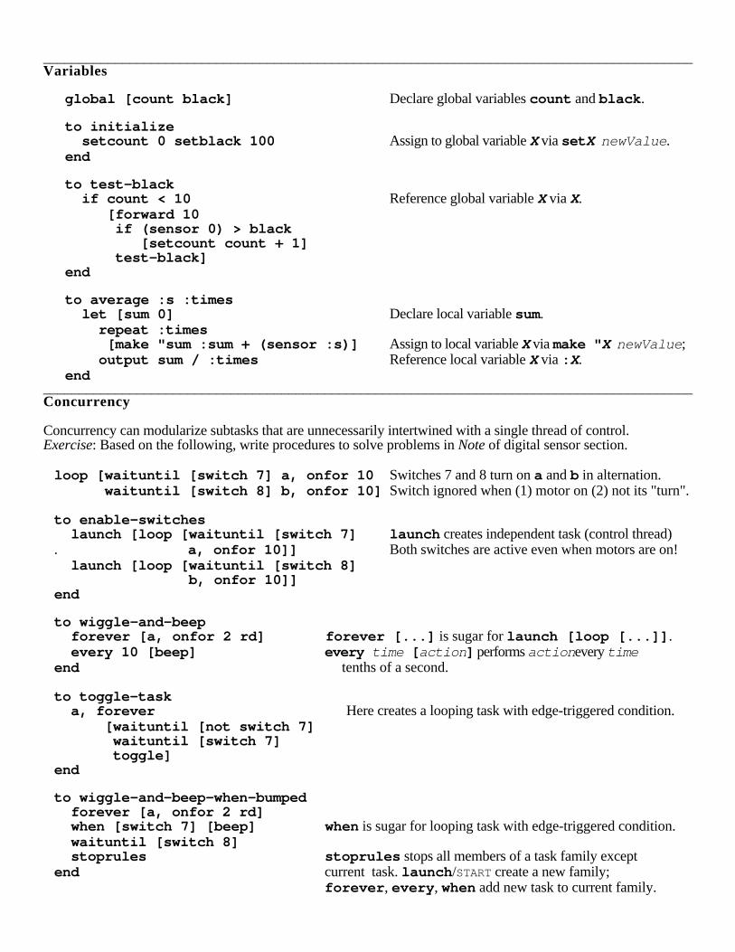
__________________________________________________________________________________________Variables
global [count black] Declare global variables count and black .
to initialize setcount 0 setblack 100 Assign to global variable X via set X newValue .end
to test-black if count < 10 Reference global variable X via X. [forward 10 if (sensor 0) > black [setcount count + 1] test-black]end
to average :s :times let [sum 0] Declare local variable sum. repeat :times [make "sum :sum + (sensor :s)] Assign to local variable X via make " X newValue ; output sum / :times Reference local variable X via : X.end
__________________________________________________________________________________________Concurrency
Concurrency can modularize subtasks that are unnecessarily intertwined with a single thread of control.Exercise: Based on the following, write procedures to solve problems in Note of digital sensor section.
loop [waituntil [switch 7] a, onfor 10 Switches 7 and 8 turn on a and b in alternation. waituntil [switch 8] b, onfor 10] Switch ignored when (1) motor on (2) not its "turn".
to enable-switches launch [loop [waituntil [switch 7] launch creates independent task (control thread). a, onfor 10]] Both switches are active even when motors are on! launch [loop [waituntil [switch 8] b, onfor 10]]end
to wiggle-and-beep forever [a, onfor 2 rd] forever [...] is sugar for launch [loop [...]] . every 10 [beep] every time [ action ] performs action every timeend tenths of a second.
to toggle-task a, forever Here creates a looping task with edge-triggered condition. [waituntil [not switch 7] waituntil [switch 7] toggle]end
to wiggle-and-beep-when-bumped forever [a, onfor 2 rd] when [switch 7] [beep] when is sugar for looping task with edge-triggered condition. waituntil [switch 8] stoprules stoprules stops all members of a task family exceptend current task. launch /START create a new family;
forever , every , when add new task to current family.
timer
resett
current timer value (-32768 -- 32767)
resets timer to 0
Timer
ir IR value (0 -- 255) sent by another Handy Board or infrared remote.
Infrared Receiver
sensor port
0 -- 6
Analog Sensorscurrent sensor value0 (high) -- 255 (low)
switch port
0 -- 15
Digital Sensorscurrent switch value0 (off) or 1 (on)
Analog sensors may be used in :0 -- 127 --> 1 (on); 128 -- 255 --> 0 (off)
switch
Digital sensors may be used in :0 (off) --> 255; 1 (on) --> 0
sensor
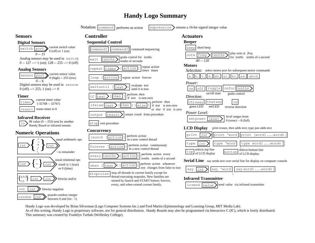
Handy Logo Summary
Handy Logo was developed by Brian Silverman (Logo Computer Systems Inc.) and Fred Martin (Epistemology and Learning Group, MIT Media Lab).As of this writing, Handy Logo is proprietary software, not for general distribution. Handy Boards may also be programmed via Interactive C (IC), which is freely distributed.This summary was created by Franklyn Turbak (Wellesley College).
ControllerSensors
Notation: expression
command1
returns a 16-bit signed integer valueperforms an action
command2 command sequencing
command
wait tenthsgrabs control for tenths of seconds
tenths
times actionrepeat
actionloop [ ]
[ ]
waituntil [ ]test
ifelse ]test [ then else[]
if test [ then ]
ActuatorsBeeper
Motors
LCD Display
Serial Line
Infrared Transmitter
Sequential Control
Concurrency
actionlaunch [ ]
actionforever [ ]
actionevery ][tenths
actionwhen [ ][test ]
note tenths
beep
freq
40 -- 120
Selection:a, ab, abcd,b, c, d, ac, bc, ad,
select motor port for subsequent motor commands
Power:
Power Level:
Direction:
offon toggle onfor tenths
thisway thatway rdgreen LED red LED reverse direction
grabs control
setpower levellevel ranges from 0 (none) -- 8 (full)
print int print " word print [ word1 wordn... ]
type int type " word type [
word1 wordn... ]
bottomtop
say int say " word say [
word1 wordn... ]
irsend value
stoprules
Numeric Operations
{ }+-*/\
int int
{ }int int
<=>
{ } int intandor
not
intrandom
int
psuedo-random integerbetween 0 and (int - 1)
repeat actiontimes times
repeataction forever
evaluate testuntil it is true
perform
thentest is non-zero
performif
test is non-zeroif or else if test is zero
stop
output result
selects top lineof LCD display
selects bottom lineof LCD display
print erases, then adds text; type just adds text
say sends text over serial line for display on computer console
sendvalue via infrared transmitter
return result from procedure
then
exit procedure
bitwise negation
bitwise and/or
usual arithmetic ops
\ is remainder
usual relational ops
result is 1 (true)or 0 (false)
action
continuously
performin a new control thread
actionperformin a new control thread
perform wheneverchanges from false to truetest
action
perform action everytenths tenths of a second
stop all threads in current family except forthread executing stoprules. New families are started by launch and START button; forever,every, and when extend current family.
on/off state
short beep
play note at for tenths tenths of a second
freq
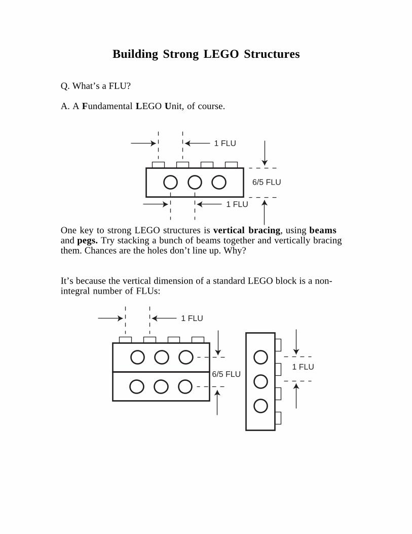
Building Strong LEGO Structures
Q. What’s a FLU?
A. A Fundamental LEGO Unit, of course.
1 FLU
6/5 FLU
1 FLU
One key to strong LEGO structures is vertical bracing, using beamsand pegs. Try stacking a bunch of beams together and vertically bracingthem. Chances are the holes don’t line up. Why?
It’s because the vertical dimension of a standard LEGO block is a non-integral number of FLUs:
1 FLU
1 FLU6/5 FLU
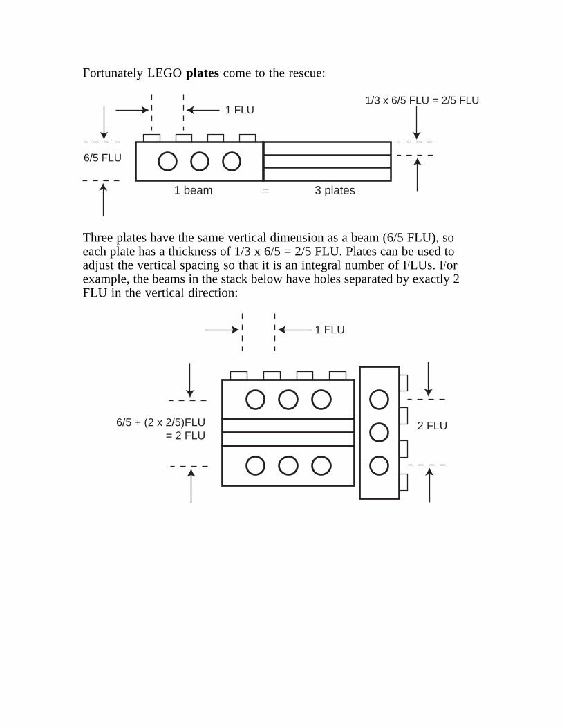
Fortunately LEGO plates come to the rescue:
1 FLU1/3 x 6/5 FLU = 2/5 FLU
6/5 FLU
3 plates1 beam =
Three plates have the same vertical dimension as a beam (6/5 FLU), soeach plate has a thickness of 1/3 x 6/5 = 2/5 FLU. Plates can be used toadjust the vertical spacing so that it is an integral number of FLUs. Forexample, the beams in the stack below have holes separated by exactly 2FLU in the vertical direction:
1 FLU
= 2 FLU2 FLU6/5 + (2 x 2/5)FLU
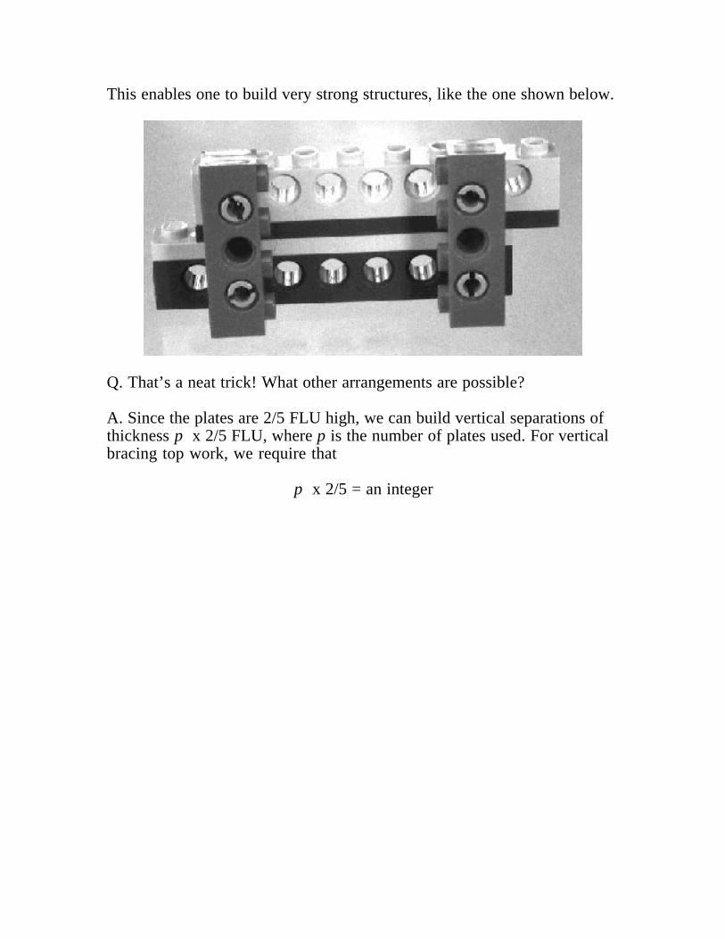
This enables one to build very strong structures, like the one shown below.
Q. That’s a neat trick! What other arrangements are possible?
A. Since the plates are 2/5 FLU high, we can build vertical separations ofthickness p x 2/5 FLU, where p is the number of plates used. For verticalbracing top work, we require that
p x 2/5 = an integer
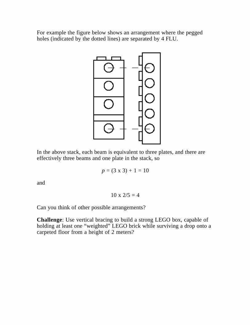
For example the figure below shows an arrangement where the peggedholes (indicated by the dotted lines) are separated by 4 FLU.
In the above stack, each beam is equivalent to three plates, and there areeffectively three beams and one plate in the stack, so
p = (3 x 3) + 1 = 10
and
10 x 2/5 = 4
Can you think of other possible arrangements?
Challenge: Use vertical bracing to build a strong LEGO box, capable ofholding at least one “weighted” LEGO brick while surviving a drop onto acarpeted floor from a height of 2 meters?
LEGO Gears and Motors
Motors are devices that convert electrical energy into mechanicalmovement. For a motor of a given design and operating voltage (LEGOmotors are designed to operate at 9 volts) there is a maximum rate atwhich electrical energy can enter the motor and, because energy isconserved, a maximum rate at which energy can be added to themechanical system.
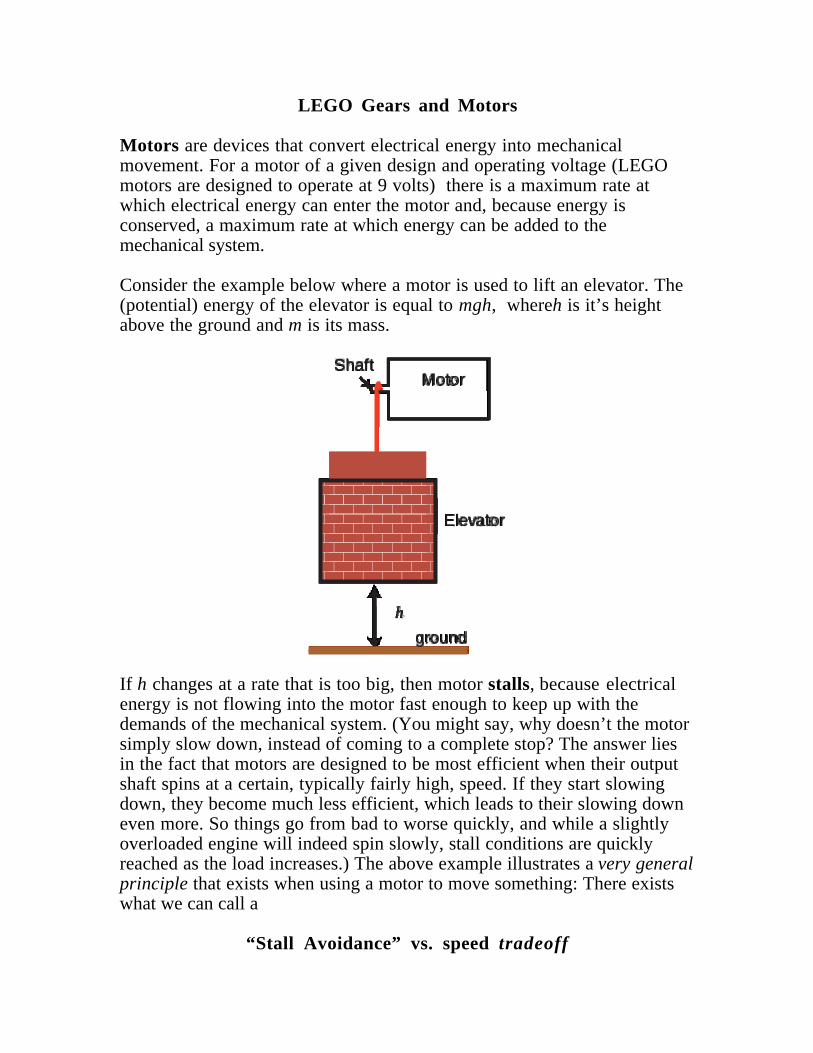
Consider the example below where a motor is used to lift an elevator. The(potential) energy of the elevator is equal to mgh, whereh is it’s heightabove the ground and m is its mass.
MotorShaft
������������yyzz{{{{||||��y{h
Elevator
ground
If h changes at a rate that is too big, then motor stalls, because electricalenergy is not flowing into the motor fast enough to keep up with thedemands of the mechanical system. (You might say, why doesn’t the motorsimply slow down, instead of coming to a complete stop? The answer liesin the fact that motors are designed to be most efficient when their outputshaft spins at a certain, typically fairly high, speed. If they start slowingdown, they become much less efficient, which leads to their slowing downeven more. So things go from bad to worse quickly, and while a slightlyoverloaded engine will indeed spin slowly, stall conditions are quicklyreached as the load increases.) The above example illustrates a very generalprinciple that exists when using a motor to move something: There existswhat we can call a
“Stall Avoidance” vs. speed tradeoff
That is, to avoid stalling the motor, we must design our mechanical systemso that the elevator is not required to rise “too quickly”.
The concept of tradeoffs is one of the “big ideas” of engineering.Understanding this particular tradeoff is the key to the Vehicle RaceChallenge.
A familiar example of this type of stall avoidance vs. speed tradeoff occurswhen you cycle up a hill. If you try to climb too fast, the “motor” (i.e. therider) stalls (collapses.)
Alternatively we can invoke the concept of torque = r x F to describewhat’s going on. Torque is a measure of the ability of the force (F) tocause a body to rotate. Consider opening a door for example. How easy itis to open the door depends on the torque exerted, which in turn dependson how hard you push (F), how far from the door’s hinge you push (r) andthe angle between F and the plane of the door. (Torque is maximized whenF is perpendicular to the plane of the door.)
Motors (or cyclists!) can be characterized by the maximum torque they canexert without stalling. We can demonstrate this by grabbing the shafts onthe gray motors and seeing what torque it takes to make them stall them.Or try climbing a steep hill on a bike without gears. Your leg is onlycapable of exerting a certain maxium torque on the pedals. And like amotor, your body is most efficient in turning the pedals at a certain fairlyhigh cadence (around 60 rpm). On a bike without gears you won’t be ableto keep up this ideal cadence on a steep hill without exceeding yourmaximum torque, (and collapsing).
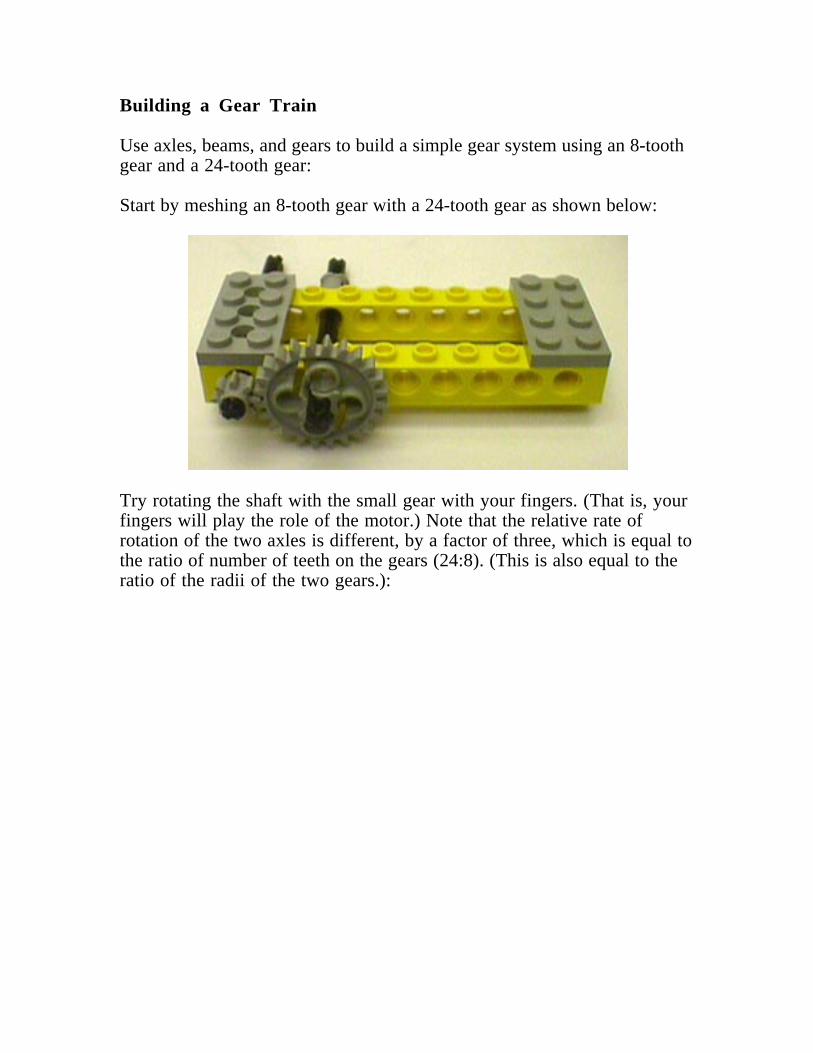
Building a Gear Train
Use axles, beams, and gears to build a simple gear system using an 8-toothgear and a 24-tooth gear:
Start by meshing an 8-tooth gear with a 24-tooth gear as shown below:
Try rotating the shaft with the small gear with your fingers. (That is, yourfingers will play the role of the motor.) Note that the relative rate ofrotation of the two axles is different, by a factor of three, which is equal tothe ratio of number of teeth on the gears (24:8). (This is also equal to theratio of the radii of the two gears.):
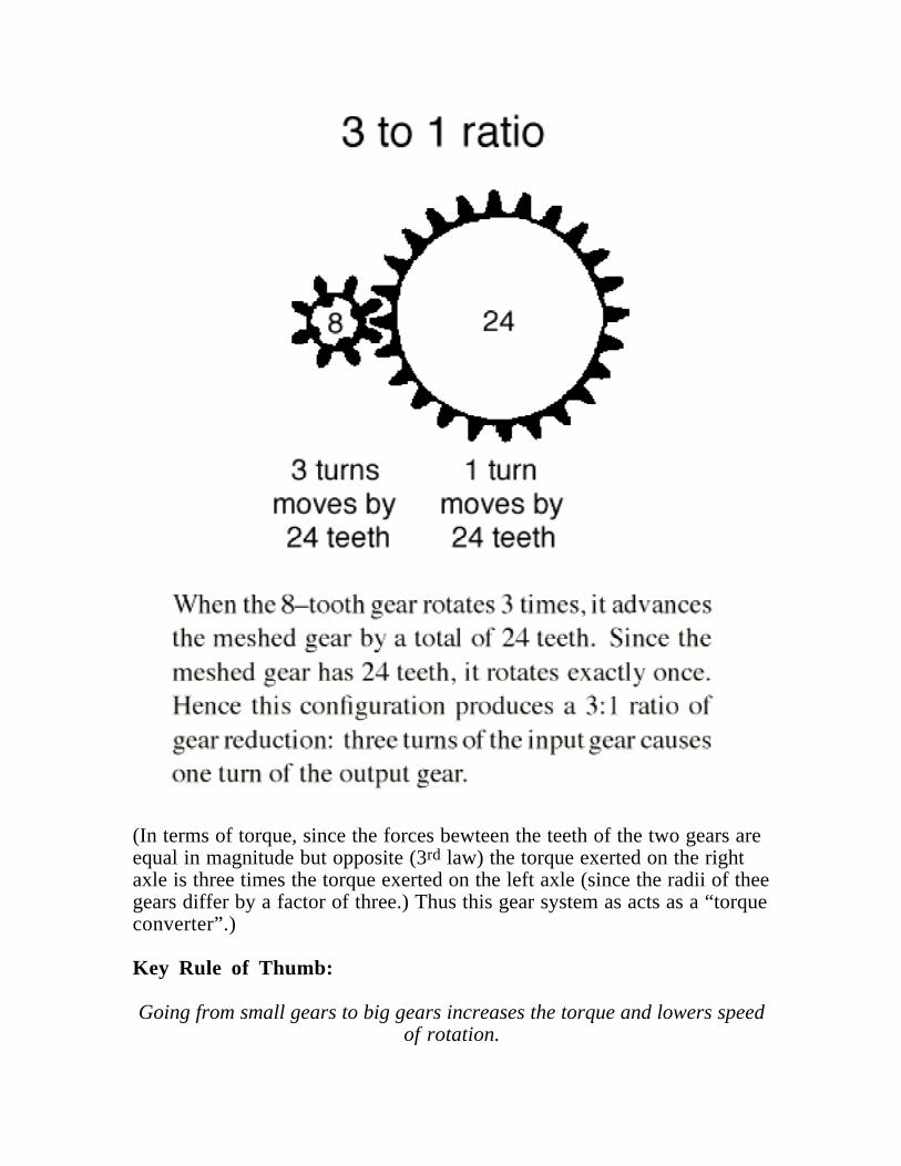
(In terms of torque, since the forces bewteen the teeth of the two gears areequal in magnitude but opposite (3rd law) the torque exerted on the rightaxle is three times the torque exerted on the left axle (since the radii of theegears differ by a factor of three.) Thus this gear system as acts as a “torqueconverter”.)
Key Rule of Thumb:
Going from small gears to big gears increases the torque and lowers speedof rotation.
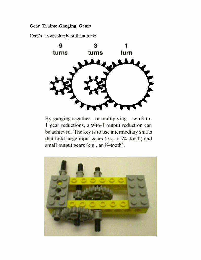
Gear Trains: Ganging Gears
Here’s an absolutely brilliant trick:
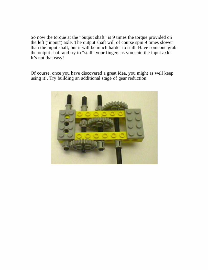
So now the torque at the “output shaft” is 9 times the torque provided onthe left (‘input”) axle. The output shaft will of course spin 9 times slowerthan the input shaft, but it will be much harder to stall. Have someone grabthe output shaft and try to “stall” your fingers as you spin the input axle.It’s not that easy!
Of course, once you have discovered a great idea, you might as well keepusing it!. Try building an additional stage of gear reduction:
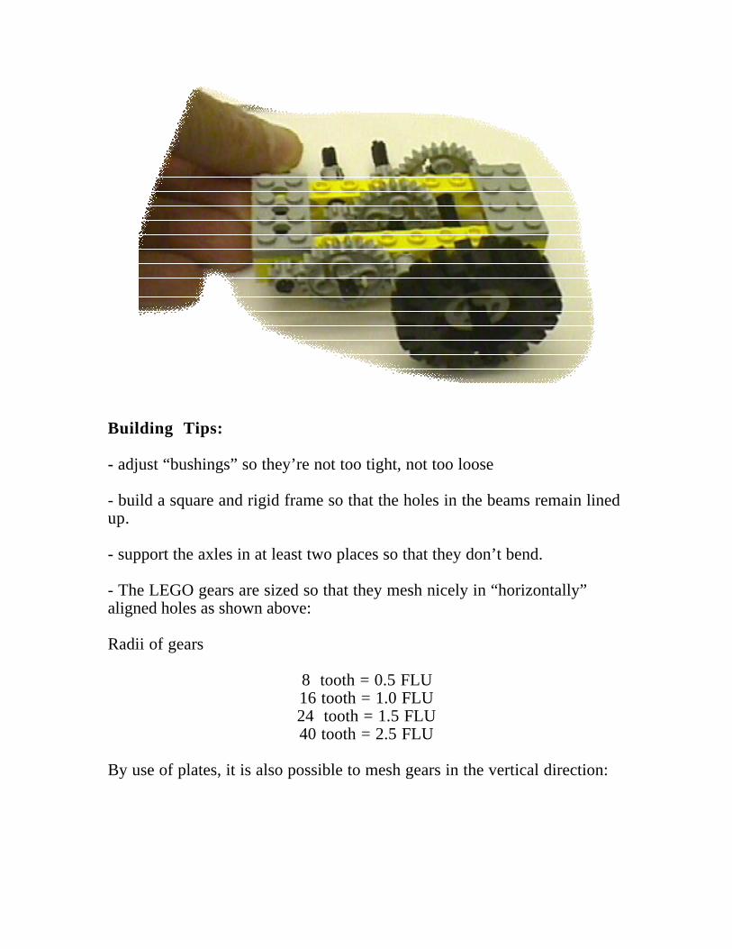
Building Tips:
- adjust “bushings” so they’re not too tight, not too loose
- build a square and rigid frame so that the holes in the beams remain linedup.
- support the axles in at least two places so that they don’t bend.
- The LEGO gears are sized so that they mesh nicely in “horizontally”aligned holes as shown above:
Radii of gears
8 tooth = 0.5 FLU16 tooth = 1.0 FLU24 tooth = 1.5 FLU40 tooth = 2.5 FLU
By use of plates, it is also possible to mesh gears in the vertical direction:
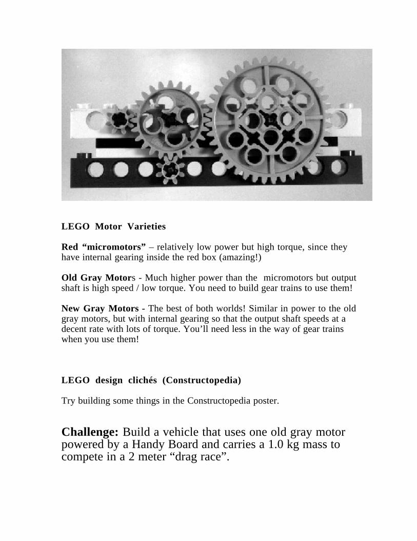
LEGO Motor Varieties
Red “micromotors” – relatively low power but high torque, since theyhave internal gearing inside the red box (amazing!)
Old Gray Motor s - Much higher power than the micromotors but outputshaft is high speed / low torque. You need to build gear trains to use them!
New Gray Motors - The best of both worlds! Similar in power to the oldgray motors, but with internal gearing so that the output shaft speeds at adecent rate with lots of torque. You’ll need less in the way of gear trainswhen you use them!
LEGO design clichés (Constructopedia)
Try building some things in the Constructopedia poster.
Challenge: Build a vehicle that uses one old gray motorpowered by a Handy Board and carries a 1.0 kg mass tocompete in a 2 meter “drag race”.
This article was originally published in The Robotics Practitioner: The Journal for Robot Builders,volume 1, number 2, Spring 1995; [email protected]
The Art of LEGO Design
Fred G. Martin1
March 15, 1995
There is a real need for better resources for both fledgling and intermediate LEGO builders. The plans that the LEGOcompany distributes with its kits are very good at showing how to build specific models, but not so good at teaching how todesign from one’s own ideas. At the MIT Media Laboratory, we’re working on a project we call the LEGO Constructopedia,a hypermedia resource for LEGO designers that will include LEGO building plans, design principles, textual descriptions,and rendered animations, all interlinked, indexed, and browsable. The project is just beginning and is still in the conceptualstages; this article is my attempt to present some of the content of our proposed LEGO Constructopedia in a more traditionalform.
The article begins with an analysis of the structural principles of the LEGO system, continues with a discussion of gears,gear reduction, and geartrains, and finishes with a visual assortment of various building tricks or “cliches.” Interspersedthroughout are numerous diagrams and sample models to illustrate the ideas being presented. I hope that LEGO aficionadosat all levels from novice to expert will find something of interest here.
Structure
The Vertical Dimension Relation
Let’s begin by examining the LEGO brick in detail. Most people realize that the LEGO brick is not based on a cubic form.The height of the brick is a larger measure than the length and width (assuming the normal viewpoint of studs on the top).But few people know the secret relationship between these dimensions: the vertical unit is precisely 6/5 times the horizontalones. Put another way, a stack of five LEGO bricks is exactly equal in height as a six-stud LEGO beam is long.
The origins of this obscure relationship remain shrouded in mystery, but it has real practical value: by building structureswith vertical heights equal to integral horizontal lengths, it is possible to use beams to brace LEGO constructions. Thistechnique is greatly facilitated by the one-third-height plates, which allow a number of vertical spacing possibilities.
The most common trick is to create two horizontal units of space in the vertical dimension by separating two beams withtwo plates (Figure 1). This 12
3 vertical measure is two units of horizontal measure since 1 23 times the conversion factor of 6/5
1The Media Laboratory at the Massachusetts Institute of Technology, 20 Ames Street Room E15–320, Cambridge, MA 02139. E-mail:[email protected]. This document is Copyright c 1995 by Fred G. Martin. It may be distributed freely in verbatim form providedthat no fee is collected for its distribution (other than reasonable reproduction costs) and this copyright notice is included. An electronic version of thisdocument is available via anonymous FTP from cherupakha.media.mit.edu (Internet 18.85.0.47) in directory pub/people/fredm.
1
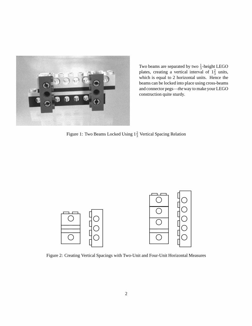
Two beams are separated by two 13 -height LEGO
plates, creating a vertical interval of 123 units,
which is equal to 2 horizontal units. Hence thebeams can be locked into place using cross-beamsand connector pegs—theway to make your LEGOconstruction quite sturdy.
Figure 1: Two Beams Locked Using 123 Vertical Spacing Relation
Figure 2: Creating Vertical Spacings with Two-Unit and Four-Unit Horizontal Measures
2
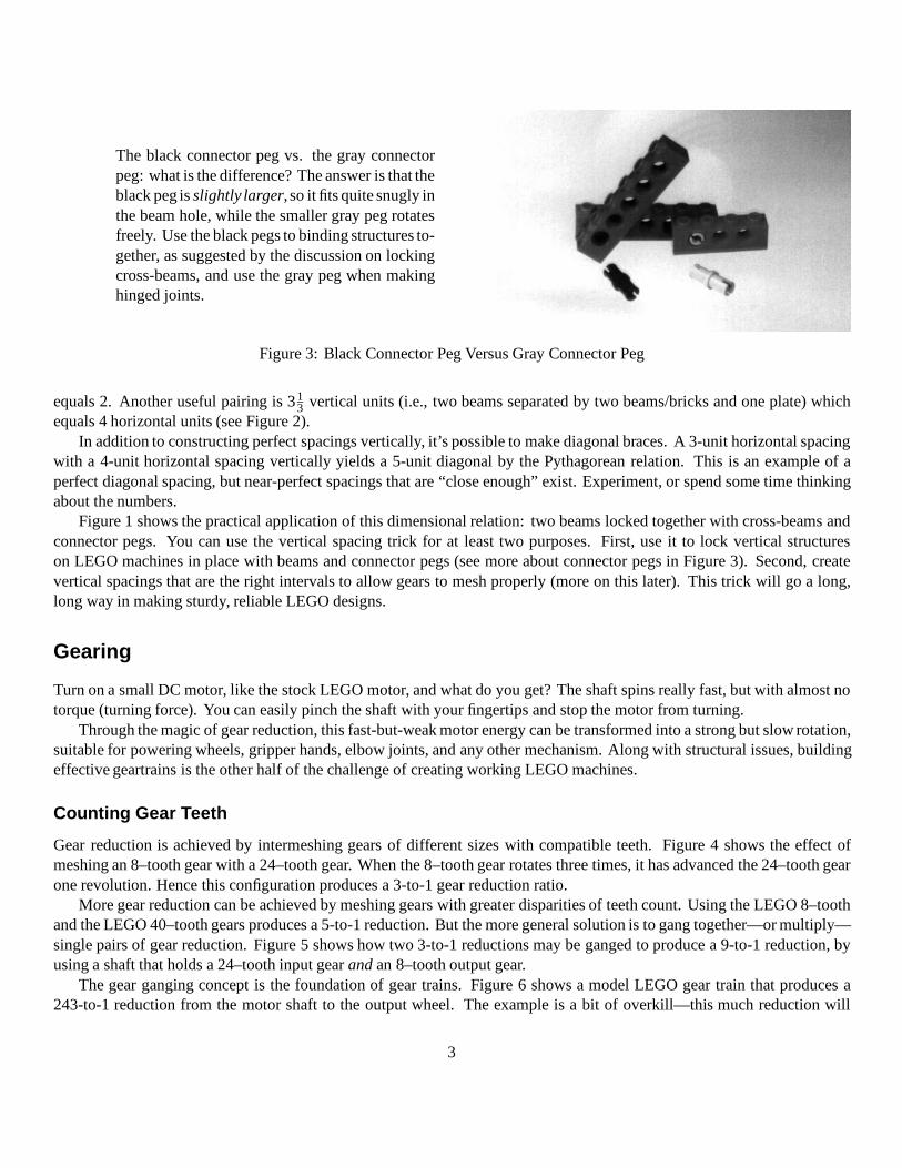
The black connector peg vs. the gray connectorpeg: what is the difference? The answer is that theblack peg is slightly larger, so it fits quite snugly inthe beam hole, while the smaller gray peg rotatesfreely. Use the black pegs to binding structures to-gether, as suggested by the discussion on lockingcross-beams, and use the gray peg when makinghinged joints.
Figure 3: Black Connector Peg Versus Gray Connector Peg
equals 2. Another useful pairing is 313 vertical units (i.e., two beams separated by two beams/bricks and one plate) which
equals 4 horizontal units (see Figure 2).In addition to constructing perfect spacings vertically, it’s possible to make diagonal braces. A 3-unit horizontal spacing
with a 4-unit horizontal spacing vertically yields a 5-unit diagonal by the Pythagorean relation. This is an example of aperfect diagonal spacing, but near-perfect spacings that are “close enough” exist. Experiment, or spend some time thinkingabout the numbers.
Figure 1 shows the practical application of this dimensional relation: two beams locked together with cross-beams andconnector pegs. You can use the vertical spacing trick for at least two purposes. First, use it to lock vertical structureson LEGO machines in place with beams and connector pegs (see more about connector pegs in Figure 3). Second, createvertical spacings that are the right intervals to allow gears to mesh properly (more on this later). This trick will go a long,long way in making sturdy, reliable LEGO designs.
Gearing
Turn on a small DC motor, like the stock LEGO motor, and what do you get? The shaft spins really fast, but with almost notorque (turning force). You can easily pinch the shaft with your fingertips and stop the motor from turning.
Through the magic of gear reduction, this fast-but-weak motor energy can be transformed into a strong but slow rotation,suitable for powering wheels, gripper hands, elbow joints, and any other mechanism. Along with structural issues, buildingeffective geartrains is the other half of the challenge of creating working LEGO machines.
Counting Gear Teeth
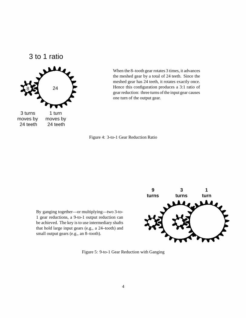
Gear reduction is achieved by intermeshing gears of different sizes with compatible teeth. Figure 4 shows the effect ofmeshing an 8–tooth gear with a 24–tooth gear. When the 8–tooth gear rotates three times, it has advanced the 24–tooth gearone revolution. Hence this configuration produces a 3-to-1 gear reduction ratio.
More gear reduction can be achieved by meshing gears with greater disparities of teeth count. Using the LEGO 8–toothand the LEGO 40–tooth gears produces a 5-to-1 reduction. But the more general solution is to gang together—or multiply—single pairs of gear reduction. Figure 5 shows how two 3-to-1 reductions may be ganged to produce a 9-to-1 reduction, byusing a shaft that holds a 24–tooth input gear and an 8–tooth output gear.
The gear ganging concept is the foundation of gear trains. Figure 6 shows a model LEGO gear train that produces a243-to-1 reduction from the motor shaft to the output wheel. The example is a bit of overkill—this much reduction will
3
8 24
3 turns moves by 24 teeth
1 turn moves by 24 teeth
3 to 1 ratio
When the 8–tooth gear rotates 3 times, it advancesthe meshed gear by a total of 24 teeth. Since themeshed gear has 24 teeth, it rotates exactly once.Hence this configuration produces a 3:1 ratio ofgear reduction: three turns of the input gear causesone turn of the output gear.
Figure 4: 3-to-1 Gear Reduction Ratio
By ganging together—or multiplying—two 3-to-1 gear reductions, a 9-to-1 output reduction canbe achieved. The key is to use intermediary shaftsthat hold large input gears (e.g., a 24–tooth) andsmall output gears (e.g., an 8–tooth).
9turns
3turns
1turn
Figure 5: 9-to-1 Gear Reduction with Ganging
4
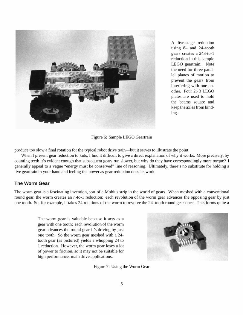
A five-stage reductionusing 8– and 24–toothgears creates a 243-to-1reduction in this sampleLEGO geartrain. Notethe need for three paral-lel planes of motion toprevent the gears frominterfering with one an-other. Four 2�3 LEGOplates are used to holdthe beams square andkeep the axles from bind-ing.
Figure 6: Sample LEGO Geartrain
produce too slow a final rotation for the typical robot drive train—but it serves to illustrate the point.When I present gear reduction to kids, I find it difficult to give a direct explanation of why it works. More precisely, by
counting teeth it’s evident enough that subsequent gears run slower, but why do they have correspondingly more torque? Igenerally appeal to a vague “energy must be conserved” line of reasoning. Ultimately, there’s no substitute for holding alive geartrain in your hand and feeling the power as gear reduction does its work.
The Worm Gear
The worm gear is a fascinating invention, sort of a Mobius strip in the world of gears. When meshed with a conventionalround gear, the worm creates an n-to-1 reduction: each revolution of the worm gear advances the opposing gear by justone tooth. So, for example, it takes 24 rotations of the worm to revolve the 24–tooth round gear once. This forms quite a
The worm gear is valuable because it acts as agear with one tooth: each revolution of the wormgear advances the round gear it’s driving by justone tooth. So the worm gear meshed with a 24-tooth gear (as pictured) yields a whopping 24 to1 reduction. However, the worm gear loses a lotof power to friction, so it may not be suitable forhigh performance, main drive applications.
Figure 7: Using the Worm Gear
5
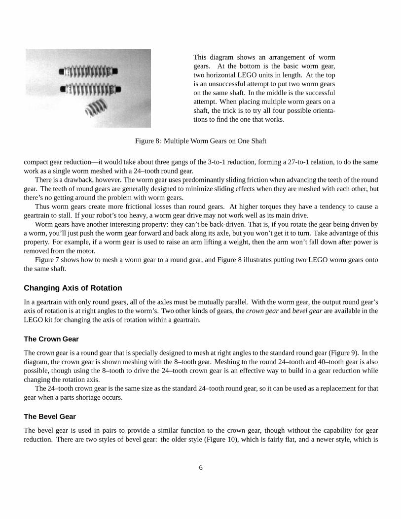
This diagram shows an arrangement of wormgears. At the bottom is the basic worm gear,two horizontal LEGO units in length. At the topis an unsuccessful attempt to put two worm gearson the same shaft. In the middle is the successfulattempt. When placing multiple worm gears on ashaft, the trick is to try all four possible orienta-tions to find the one that works.
Figure 8: Multiple Worm Gears on One Shaft
compact gear reduction—it would take about three gangs of the 3-to-1 reduction, forming a 27-to-1 relation, to do the samework as a single worm meshed with a 24–tooth round gear.
There is a drawback, however. The worm gear uses predominantly sliding friction when advancing the teeth of the roundgear. The teeth of round gears are generally designed to minimize sliding effects when they are meshed with each other, butthere’s no getting around the problem with worm gears.
Thus worm gears create more frictional losses than round gears. At higher torques they have a tendency to cause ageartrain to stall. If your robot’s too heavy, a worm gear drive may not work well as its main drive.
Worm gears have another interesting property: they can’t be back-driven. That is, if you rotate the gear being driven bya worm, you’ll just push the worm gear forward and back along its axle, but you won’t get it to turn. Take advantage of thisproperty. For example, if a worm gear is used to raise an arm lifting a weight, then the arm won’t fall down after power isremoved from the motor.
Figure 7 shows how to mesh a worm gear to a round gear, and Figure 8 illustrates putting two LEGO worm gears ontothe same shaft.
Changing Axis of Rotation
In a geartrain with only round gears, all of the axles must be mutually parallel. With the worm gear, the output round gear’saxis of rotation is at right angles to the worm’s. Two other kinds of gears, the crown gear and bevel gear are available in theLEGO kit for changing the axis of rotation within a geartrain.
The Crown Gear
The crown gear is a round gear that is specially designed to mesh at right angles to the standard round gear (Figure 9). In thediagram, the crown gear is shown meshing with the 8–tooth gear. Meshing to the round 24–tooth and 40–tooth gear is alsopossible, though using the 8–tooth to drive the 24–tooth crown gear is an effective way to build in a gear reduction whilechanging the rotation axis.
The 24–tooth crown gear is the same size as the standard 24–tooth round gear, so it can be used as a replacement for thatgear when a parts shortage occurs.
The Bevel Gear
The bevel gear is used in pairs to provide a similar function to the crown gear, though without the capability for gearreduction. There are two styles of bevel gear: the older style (Figure 10), which is fairly flat, and a newer style, which is
6
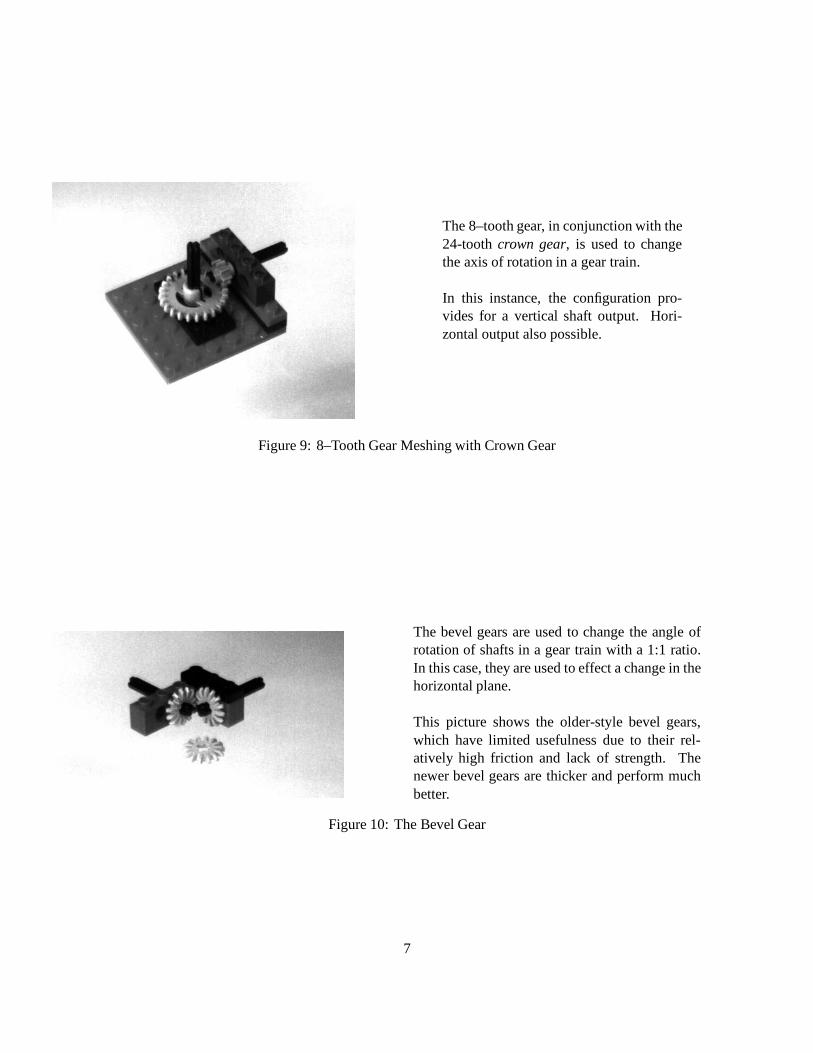
The 8–tooth gear, in conjunction with the24-tooth crown gear, is used to changethe axis of rotation in a gear train.
In this instance, the configuration pro-vides for a vertical shaft output. Hori-zontal output also possible.
Figure 9: 8–Tooth Gear Meshing with Crown Gear
The bevel gears are used to change the angle ofrotation of shafts in a gear train with a 1:1 ratio.In this case, they are used to effect a change in thehorizontal plane.
This picture shows the older-style bevel gears,which have limited usefulness due to their rel-atively high friction and lack of strength. Thenewer bevel gears are thicker and perform muchbetter.
Figure 10: The Bevel Gear
7
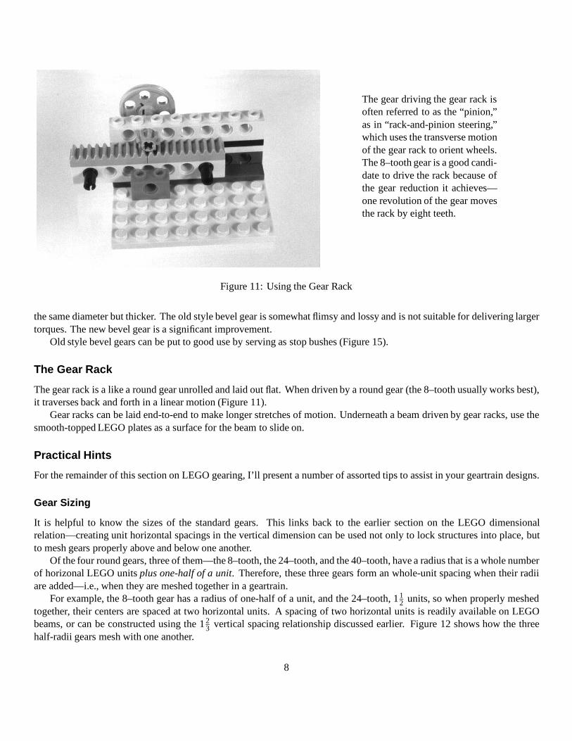
The gear driving the gear rack isoften referred to as the “pinion,”as in “rack-and-pinion steering,”which uses the transverse motionof the gear rack to orient wheels.The 8–tooth gear is a good candi-date to drive the rack because ofthe gear reduction it achieves—one revolution of the gear movesthe rack by eight teeth.
Figure 11: Using the Gear Rack
the same diameter but thicker. The old style bevel gear is somewhat flimsy and lossy and is not suitable for delivering largertorques. The new bevel gear is a significant improvement.
Old style bevel gears can be put to good use by serving as stop bushes (Figure 15).
The Gear Rack
The gear rack is a like a round gear unrolled and laid out flat. When driven by a round gear (the 8–tooth usually works best),it traverses back and forth in a linear motion (Figure 11).
Gear racks can be laid end-to-end to make longer stretches of motion. Underneath a beam driven by gear racks, use thesmooth-topped LEGO plates as a surface for the beam to slide on.
Practical Hints
For the remainder of this section on LEGO gearing, I’ll present a number of assorted tips to assist in your geartrain designs.
Gear Sizing
It is helpful to know the sizes of the standard gears. This links back to the earlier section on the LEGO dimensionalrelation—creating unit horizontal spacings in the vertical dimension can be used not only to lock structures into place, butto mesh gears properly above and below one another.
Of the four round gears, three of them—the 8–tooth, the 24–tooth, and the 40–tooth, have a radius that is a whole numberof horizonal LEGO units plus one-half of a unit. Therefore, these three gears form an whole-unit spacing when their radiiare added—i.e., when they are meshed together in a geartrain.
For example, the 8–tooth gear has a radius of one-half of a unit, and the 24–tooth, 112 units, so when properly meshed
together, their centers are spaced at two horizontal units. A spacing of two horizontal units is readily available on LEGObeams, or can be constructed using the 1 2
3 vertical spacing relationship discussed earlier. Figure 12 shows how the threehalf-radii gears mesh with one another.
8
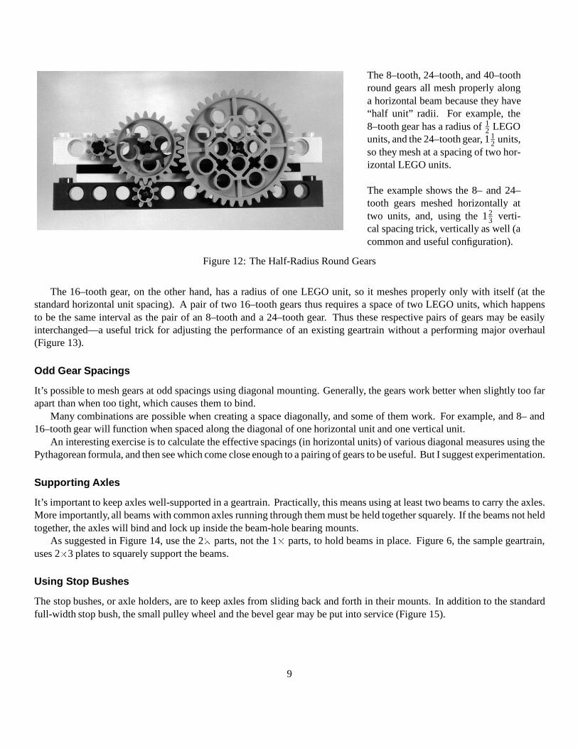
The 8–tooth, 24–tooth, and 40–toothround gears all mesh properly alonga horizontal beam because they have“half unit” radii. For example, the8–tooth gear has a radius of 1
2 LEGOunits, and the 24–tooth gear, 1 1
2 units,so they mesh at a spacing of two hor-izontal LEGO units.
The example shows the 8– and 24–tooth gears meshed horizontally attwo units, and, using the 1 2
3 verti-cal spacing trick, vertically as well (acommon and useful configuration).
Figure 12: The Half-Radius Round Gears
The 16–tooth gear, on the other hand, has a radius of one LEGO unit, so it meshes properly only with itself (at thestandard horizontal unit spacing). A pair of two 16–tooth gears thus requires a space of two LEGO units, which happensto be the same interval as the pair of an 8–tooth and a 24–tooth gear. Thus these respective pairs of gears may be easilyinterchanged—a useful trick for adjusting the performance of an existing geartrain without a performing major overhaul(Figure 13).
Odd Gear Spacings
It’s possible to mesh gears at odd spacings using diagonal mounting. Generally, the gears work better when slightly too farapart than when too tight, which causes them to bind.
Many combinations are possible when creating a space diagonally, and some of them work. For example, and 8– and16–tooth gear will function when spaced along the diagonal of one horizontal unit and one vertical unit.
An interesting exercise is to calculate the effective spacings (in horizontal units) of various diagonal measures using thePythagorean formula, and then see which come close enough to a pairing of gears to be useful. But I suggest experimentation.
Supporting Axles
It’s important to keep axles well-supported in a geartrain. Practically, this means using at least two beams to carry the axles.More importantly, all beams with common axles running through them must be held together squarely. If the beams not heldtogether, the axles will bind and lock up inside the beam-hole bearing mounts.
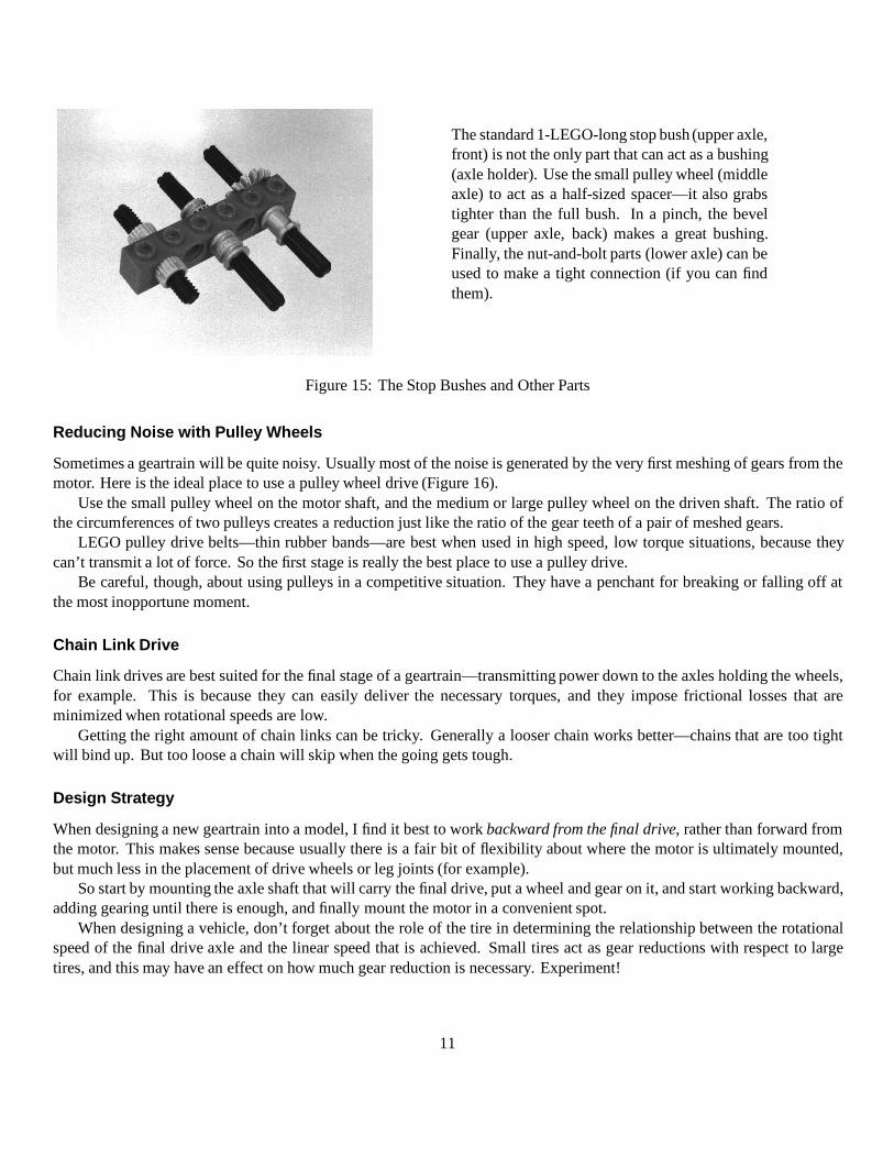
As suggested in Figure 14, use the 2� parts, not the 1� parts, to hold beams in place. Figure 6, the sample geartrain,uses 2�3 plates to squarely support the beams.
Using Stop Bushes
The stop bushes, or axle holders, are to keep axles from sliding back and forth in their mounts. In addition to the standardfull-width stop bush, the small pulley wheel and the bevel gear may be put into service (Figure 15).
9
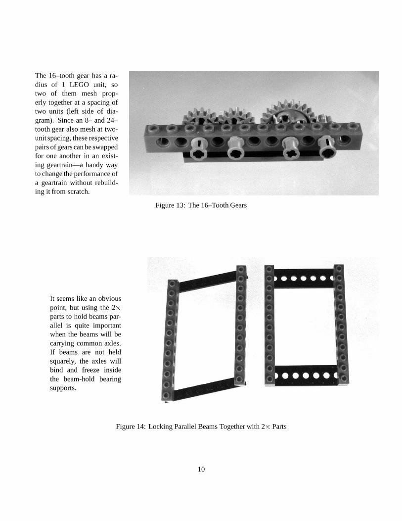
The 16–tooth gear has a ra-dius of 1 LEGO unit, sotwo of them mesh prop-erly together at a spacing oftwo units (left side of dia-gram). Since an 8– and 24–tooth gear also mesh at two-unit spacing, these respectivepairs of gears can be swappedfor one another in an exist-ing geartrain—a handy wayto change the performance ofa geartrain without rebuild-ing it from scratch.
Figure 13: The 16–Tooth Gears
It seems like an obviouspoint, but using the 2�parts to hold beams par-allel is quite importantwhen the beams will becarrying common axles.If beams are not heldsquarely, the axles willbind and freeze insidethe beam-hold bearingsupports.
Figure 14: Locking Parallel Beams Together with 2� Parts
10
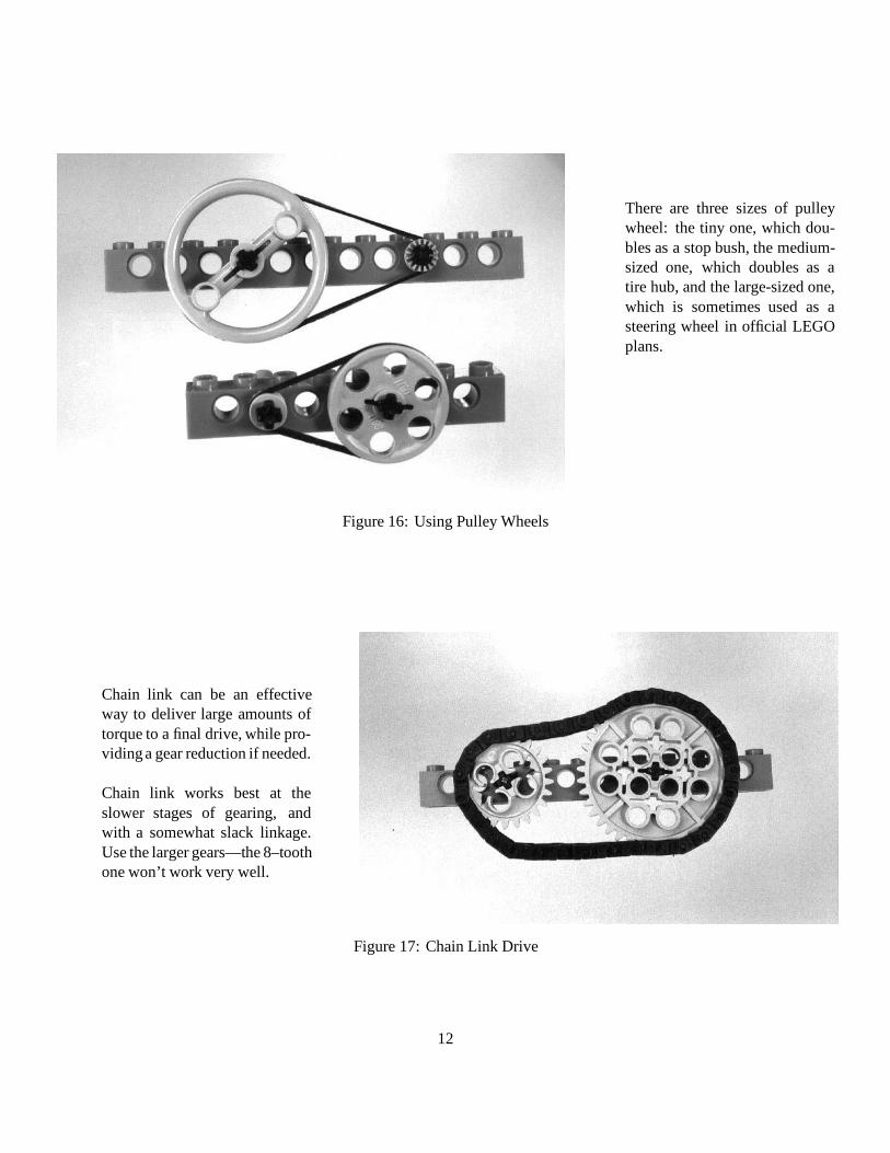
The standard 1-LEGO-long stop bush (upper axle,front) is not the only part that can act as a bushing(axle holder). Use the small pulley wheel (middleaxle) to act as a half-sized spacer—it also grabstighter than the full bush. In a pinch, the bevelgear (upper axle, back) makes a great bushing.Finally, the nut-and-bolt parts (lower axle) can beused to make a tight connection (if you can findthem).
Figure 15: The Stop Bushes and Other Parts
Reducing Noise with Pulley Wheels
Sometimes a geartrain will be quite noisy. Usually most of the noise is generated by the very first meshing of gears from themotor. Here is the ideal place to use a pulley wheel drive (Figure 16).
Use the small pulley wheel on the motor shaft, and the medium or large pulley wheel on the driven shaft. The ratio ofthe circumferences of two pulleys creates a reduction just like the ratio of the gear teeth of a pair of meshed gears.
LEGO pulley drive belts—thin rubber bands—are best when used in high speed, low torque situations, because theycan’t transmit a lot of force. So the first stage is really the best place to use a pulley drive.
Be careful, though, about using pulleys in a competitive situation. They have a penchant for breaking or falling off atthe most inopportune moment.
Chain Link Drive
Chain link drives are best suited for the final stage of a geartrain—transmitting power down to the axles holding the wheels,for example. This is because they can easily deliver the necessary torques, and they impose frictional losses that areminimized when rotational speeds are low.
Getting the right amount of chain links can be tricky. Generally a looser chain works better—chains that are too tightwill bind up. But too loose a chain will skip when the going gets tough.
Design Strategy
When designing a new geartrain into a model, I find it best to work backward from the final drive, rather than forward fromthe motor. This makes sense because usually there is a fair bit of flexibility about where the motor is ultimately mounted,but much less in the placement of drive wheels or leg joints (for example).
So start by mounting the axle shaft that will carry the final drive, put a wheel and gear on it, and start working backward,adding gearing until there is enough, and finally mount the motor in a convenient spot.
When designing a vehicle, don’t forget about the role of the tire in determining the relationship between the rotationalspeed of the final drive axle and the linear speed that is achieved. Small tires act as gear reductions with respect to largetires, and this may have an effect on how much gear reduction is necessary. Experiment!
11
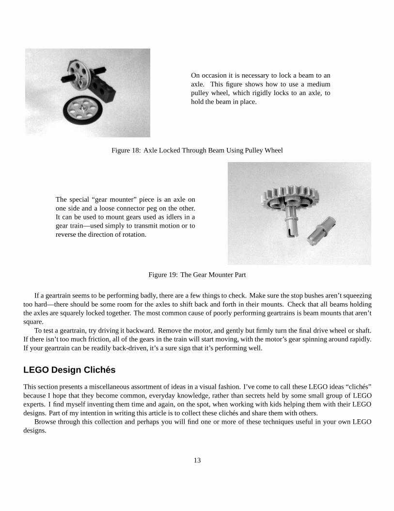
There are three sizes of pulleywheel: the tiny one, which dou-bles as a stop bush, the medium-sized one, which doubles as atire hub, and the large-sized one,which is sometimes used as asteering wheel in official LEGOplans.
Figure 16: Using Pulley Wheels
Chain link can be an effectiveway to deliver large amounts oftorque to a final drive, while pro-viding a gear reduction if needed.
Chain link works best at theslower stages of gearing, andwith a somewhat slack linkage.Use the larger gears—the 8–toothone won’t work very well.
Figure 17: Chain Link Drive
12
On occasion it is necessary to lock a beam to anaxle. This figure shows how to use a mediumpulley wheel, which rigidly locks to an axle, tohold the beam in place.
Figure 18: Axle Locked Through Beam Using Pulley Wheel
The special “gear mounter” piece is an axle onone side and a loose connector peg on the other.It can be used to mount gears used as idlers in agear train—used simply to transmit motion or toreverse the direction of rotation.
Figure 19: The Gear Mounter Part
If a geartrain seems to be performing badly, there are a few things to check. Make sure the stop bushes aren’t squeezingtoo hard—there should be some room for the axles to shift back and forth in their mounts. Check that all beams holdingthe axles are squarely locked together. The most common cause of poorly performing geartrains is beam mounts that aren’tsquare.
To test a geartrain, try driving it backward. Remove the motor, and gently but firmly turn the final drive wheel or shaft.If there isn’t too much friction, all of the gears in the train will start moving, with the motor’s gear spinning around rapidly.If your geartrain can be readily back-driven, it’s a sure sign that it’s performing well.
LEGO Design Cliches
This section presents a miscellaneous assortment of ideas in a visual fashion. I’ve come to call these LEGO ideas “cliches”because I hope that they become common, everyday knowledge, rather than secrets held by some small group of LEGOexperts. I find myself inventing them time and again, on the spot, when working with kids helping them with their LEGOdesigns. Part of my intention in writing this article is to collect these cliches and share them with others.
Browse through this collection and perhaps you will find one or more of these techniques useful in your own LEGOdesigns.
13
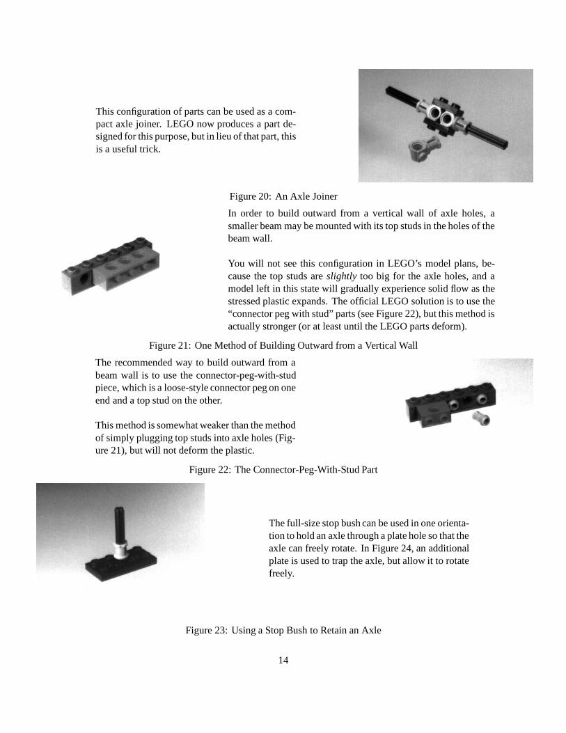
This configuration of parts can be used as a com-pact axle joiner. LEGO now produces a part de-signed for this purpose, but in lieu of that part, thisis a useful trick.
Figure 20: An Axle Joiner
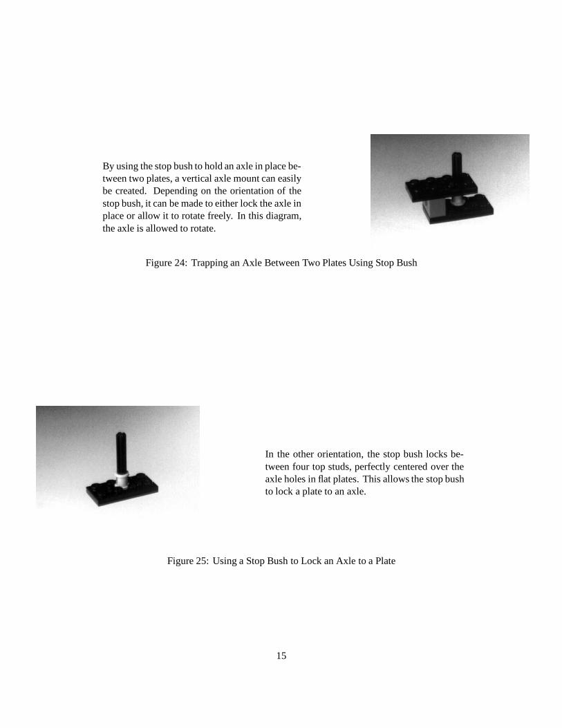
In order to build outward from a vertical wall of axle holes, asmaller beam may be mounted with its top studs in the holes of thebeam wall.
You will not see this configuration in LEGO’s model plans, be-cause the top studs are slightly too big for the axle holes, and amodel left in this state will gradually experience solid flow as thestressed plastic expands. The official LEGO solution is to use the“connector peg with stud” parts (see Figure 22), but this method isactually stronger (or at least until the LEGO parts deform).
Figure 21: One Method of Building Outward from a Vertical Wall
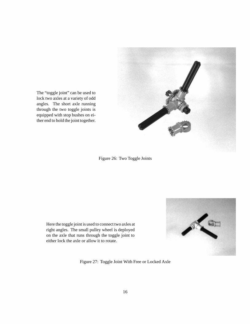
The recommended way to build outward from abeam wall is to use the connector-peg-with-studpiece, which is a loose-style connector peg on oneend and a top stud on the other.
This method is somewhat weaker than the methodof simply plugging top studs into axle holes (Fig-ure 21), but will not deform the plastic.
Figure 22: The Connector-Peg-With-Stud Part
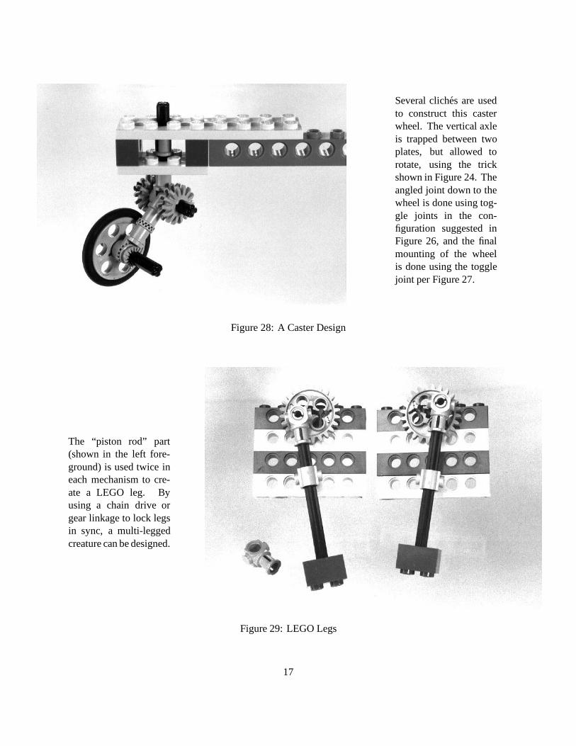
The full-size stop bush can be used in one orienta-tion to hold an axle through a plate hole so that theaxle can freely rotate. In Figure 24, an additionalplate is used to trap the axle, but allow it to rotatefreely.
Figure 23: Using a Stop Bush to Retain an Axle
14
By using the stop bush to hold an axle in place be-tween two plates, a vertical axle mount can easilybe created. Depending on the orientation of thestop bush, it can be made to either lock the axle inplace or allow it to rotate freely. In this diagram,the axle is allowed to rotate.
Figure 24: Trapping an Axle Between Two Plates Using Stop Bush
In the other orientation, the stop bush locks be-tween four top studs, perfectly centered over theaxle holes in flat plates. This allows the stop bushto lock a plate to an axle.
Figure 25: Using a Stop Bush to Lock an Axle to a Plate
15
The “toggle joint” can be used tolock two axles at a variety of oddangles. The short axle runningthrough the two toggle joints isequipped with stop bushes on ei-ther end to hold the joint together.
Figure 26: Two Toggle Joints
Here the toggle joint is used to connect two axles atright angles. The small pulley wheel is deployedon the axle that runs through the toggle joint toeither lock the axle or allow it to rotate.
Figure 27: Toggle Joint With Free or Locked Axle
16
Several cliches are usedto construct this casterwheel. The vertical axleis trapped between twoplates, but allowed torotate, using the trickshown in Figure 24. Theangled joint down to thewheel is done using tog-gle joints in the con-figuration suggested inFigure 26, and the finalmounting of the wheelis done using the togglejoint per Figure 27.
Figure 28: A Caster Design
The “piston rod” part(shown in the left fore-ground) is used twice ineach mechanism to cre-ate a LEGO leg. Byusing a chain drive orgear linkage to lock legsin sync, a multi-leggedcreature can be designed.
Figure 29: LEGO Legs
17
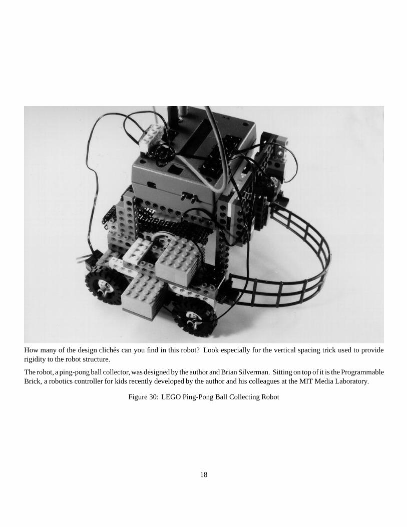
How many of the design cliches can you find in this robot? Look especially for the vertical spacing trick used to providerigidity to the robot structure.
The robot, a ping-pong ball collector, was designed by the author and Brian Silverman. Sitting on top of it is the ProgrammableBrick, a robotics controller for kids recently developed by the author and his colleagues at the MIT Media Laboratory.
Figure 30: LEGO Ping-Pong Ball Collecting Robot
18
Closing
I hope that this article inspires others to contribute LEGO design cliches from their own vocabulary to a larger collection ofresources for LEGO builders. By the time this article is printed, we will open a World Wide Web site representing successiveversions of our LEGO Constructopedia, presenting these ideas in a hypermedia format and soliciting the contributions ofothers.
Acknowledgments
Steve Ocko guided my early work with the LEGO Technic system, and continues to inspire me with his LEGO creativityand his dedication to developing rich learning environments for kids. Mike Plusch and Randy Sargent, both LEGO geniuses,shared numerous ideas and insights with me, which I’ve incorporated into this article.
The LEGO Group is a continuing sponsor of our work at the Media Laboratory. They have provided both generousresearch funding and valued intellectual discourse on a wide range of topics related to children’s learning and effective useof the LEGO materials. We are deeply grateful to their support of our work. Any criticism I make about their productsshould be taken in the spirit of making a great thing even better.
About the Author
Fred Martin has been developing educational robotics technologies at the MIT Media Laboratory since 1986, and is aco-founder of the annual MIT LEGO Robot Design Competition.
Fred is interested in robotics for fun and as a vehicle for exploring sensing, control, and engineering design. He has beenteaching robotics to kids, teenagers, college students, and adults for nearly ten years and hasn’t gotten tired of it yet.
Currently a Postdoctoral Fellow at the Media Lab, Fred is working on a robotics textbook aimed at undergraduateengineering students. Tentatively entitled The Art of Robotics: A Hands-On Introduction to Engineering, the book isscheduled to be published in the fall of 1996 by Benjamin/Cummings. This article will form the basis of an expanded chapteron LEGO design in the text.
Fred welcomes any comments on this article. He can be reached at [email protected]. The URL for theLEGO Constructopedia WWW site is:
http://el.www.media.mit.edu/groups/el/Projects/constructopedia
19
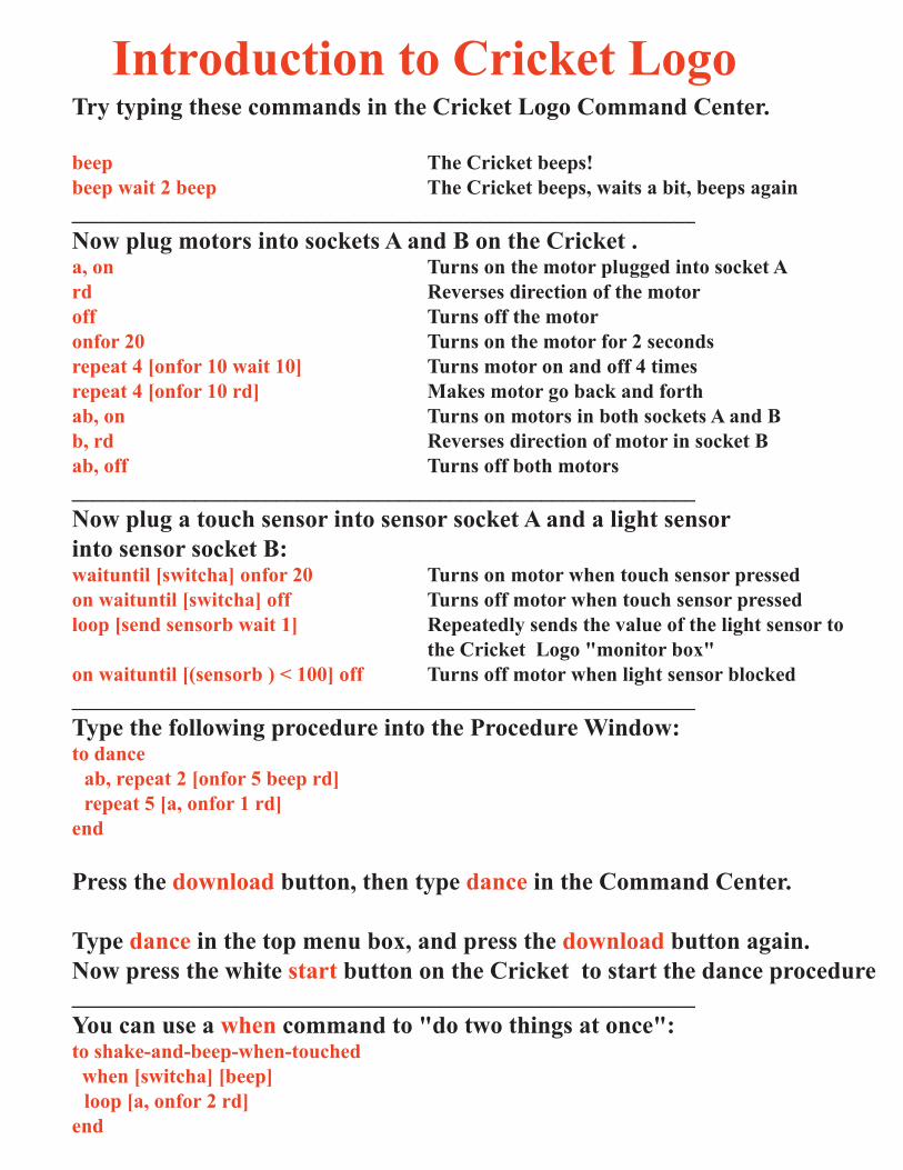

Communicating with Crickets
Here’s an outline of how you can go about making your own “Dancing Crickets”. Startby building two LEGO “creatures,” each with two motors and a Cricket to control them.
One of the creatures will act as a “leader,” the other as a “follower”.Here is a procedure for the leader:
to leadab, repeat 6 [onfor 10 rd] ; do a little dancesend 1 ; send a signal to indicate
; “I’m done with my dance”waituntil [newir?] ; wait for signal from the followerlead
end
The leader does a dance, sends a signal to the follower telling it to do a dance, and thenwaits for a response before repeating its own dance.
Here is a procedure for the follower:
to followwaituntil [newir?] ; wait for signal from the leaderab, repeat 10 [onfor 5 rd] ; do a little dancesend 2 ; send a signal to indicate
; “I’m done with my dance”fol low
end
Download the procedures into both Crickets. Start the lead procedure running in oneCricket and the follow procedure in the other Cricket. And watch the Crickets dance!
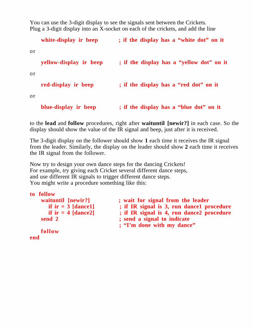
You can use the 3-digit display to see the signals sent between the Crickets.Plug a 3-digit display into an X-socket on each of the crickets, and add the line
white-display ir beep ; if the display has a “white dot” on it
or
yellow-display ir beep ; if the display has a “yellow dot” on it
or
red-display ir beep ; if the display has a “red dot” on it
or
blue-display ir beep ; if the display has a “blue dot” on it
to the lead and follow procedures, right after waituntil [newir?] in each case. So thedisplay should show the value of the IR signal and beep, just after it is received.
The 3-digit display on the follower should show 1 each time it receives the IR signalfrom the leader. Similarly, the display on the leader should show 2 each time it receivesthe IR signal from the follower.
Now try to design your own dance steps for the dancing Crickets!For example, try giving each Cricket several different dance steps,and use different IR signals to trigger different dance steps.You might write a procedure something like this:
to followwaituntil [newir?] ; wait for signal from the leader
if ir = 3 [dance1] ; if IR signal is 3, run dance1 procedure if ir = 4 [dance2] ; if IR signal is 4, run dance2 procedure
send 2 ; send a signal to indicate; “I’m done with my dance”
fol lowend
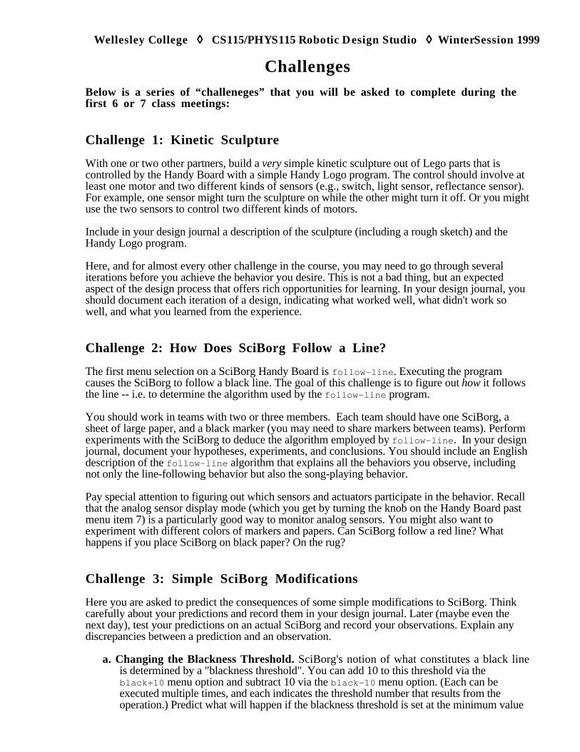
Wellesley College ◊◊◊◊ CS115/PHYS115 Robotic Design Studio ◊◊◊◊ WinterSession 1999
ChallengesBelow is a series of “challeneges” that you will be asked to complete during thefirst 6 or 7 class meetings:
Challenge 1: Kinetic Sculpture
With one or two other partners, build a very simple kinetic sculpture out of Lego parts that iscontrolled by the Handy Board with a simple Handy Logo program. The control should involve atleast one motor and two different kinds of sensors (e.g., switch, light sensor, reflectance sensor).For example, one sensor might turn the sculpture on while the other might turn it off. Or you mightuse the two sensors to control two different kinds of motors.
Include in your design journal a description of the sculpture (including a rough sketch) and theHandy Logo program.
Here, and for almost every other challenge in the course, you may need to go through severaliterations before you achieve the behavior you desire. This is not a bad thing, but an expectedaspect of the design process that offers rich opportunities for learning. In your design journal, youshould document each iteration of a design, indicating what worked well, what didn't work sowell, and what you learned from the experience.
Challenge 2: How Does SciBorg Follow a Line?
The first menu selection on a SciBorg Handy Board is follow-line . Executing the programcauses the SciBorg to follow a black line. The goal of this challenge is to figure out how it followsthe line -- i.e. to determine the algorithm used by the follow-line program.
You should work in teams with two or three members. Each team should have one SciBorg, asheet of large paper, and a black marker (you may need to share markers between teams). Performexperiments with the SciBorg to deduce the algorithm employed by follow-line . In your designjournal, document your hypotheses, experiments, and conclusions. You should include an Englishdescription of the follow-line algorithm that explains all the behaviors you observe, includingnot only the line-following behavior but also the song-playing behavior.
Pay special attention to figuring out which sensors and actuators participate in the behavior. Recallthat the analog sensor display mode (which you get by turning the knob on the Handy Board pastmenu item 7) is a particularly good way to monitor analog sensors. You might also want toexperiment with different colors of markers and papers. Can SciBorg follow a red line? Whathappens if you place SciBorg on black paper? On the rug?
Challenge 3: Simple SciBorg Modifications
Here you are asked to predict the consequences of some simple modifications to SciBorg. Thinkcarefully about your predictions and record them in your design journal. Later (maybe even thenext day), test your predictions on an actual SciBorg and record your observations. Explain anydiscrepancies between a prediction and an observation.
a. Changing the Blackness Threshold. SciBorg's notion of what constitutes a black lineis determined by a "blackness threshold". You can add 10 to this threshold via theblack+10 menu option and subtract 10 via the black-10 menu option. (Each can beexecuted multiple times, and each indicates the threshold number that results from theoperation.) Predict what will happen if the blackness threshold is set at the minimum value
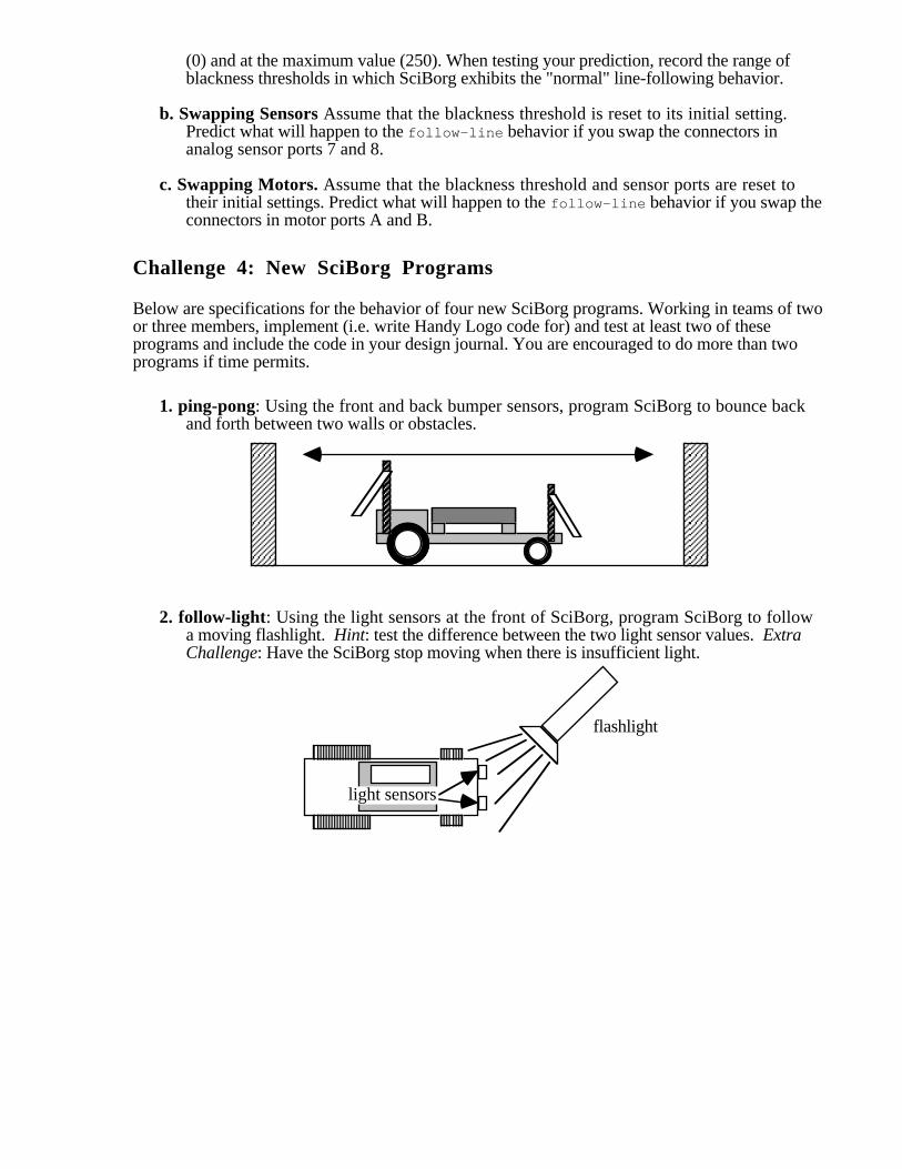
(0) and at the maximum value (250). When testing your prediction, record the range ofblackness thresholds in which SciBorg exhibits the "normal" line-following behavior.
b. Swapping Sensors Assume that the blackness threshold is reset to its initial setting.Predict what will happen to the follow-line behavior if you swap the connectors inanalog sensor ports 7 and 8.
c. Swapping Motors. Assume that the blackness threshold and sensor ports are reset totheir initial settings. Predict what will happen to the follow-line behavior if you swap theconnectors in motor ports A and B.
Challenge 4: New SciBorg Programs
Below are specifications for the behavior of four new SciBorg programs. Working in teams of twoor three members, implement (i.e. write Handy Logo code for) and test at least two of theseprograms and include the code in your design journal. You are encouraged to do more than twoprograms if time permits.
1. ping-pong: Using the front and back bumper sensors, program SciBorg to bounce backand forth between two walls or obstacles.
2. follow-light: Using the light sensors at the front of SciBorg, program SciBorg to followa moving flashlight. Hint: test the difference between the two light sensor values. ExtraChallenge: Have the SciBorg stop moving when there is insufficient light.
flashlight
light sensors
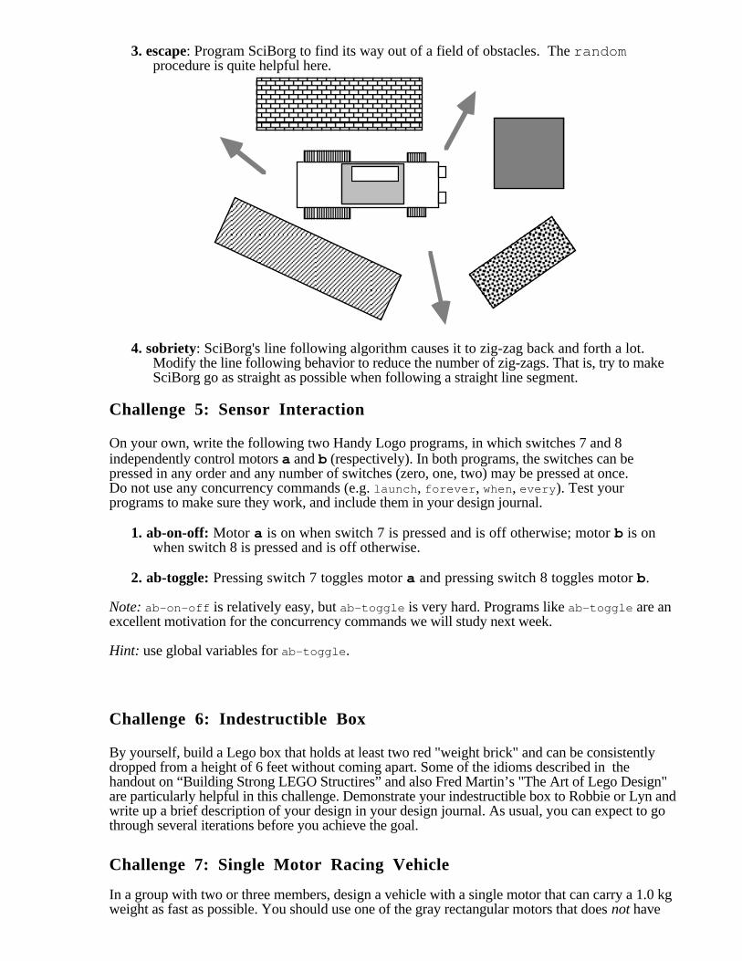
3. escape: Program SciBorg to find its way out of a field of obstacles. The randomprocedure is quite helpful here.
4. sobriety: SciBorg's line following algorithm causes it to zig-zag back and forth a lot.Modify the line following behavior to reduce the number of zig-zags. That is, try to makeSciBorg go as straight as possible when following a straight line segment.
Challenge 5: Sensor Interaction
On your own, write the following two Handy Logo programs, in which switches 7 and 8independently control motors a and b (respectively). In both programs, the switches can bepressed in any order and any number of switches (zero, one, two) may be pressed at once.Do not use any concurrency commands (e.g. launch , forever , when, every ). Test yourprograms to make sure they work, and include them in your design journal.
1. ab-on-off: Motor a is on when switch 7 is pressed and is off otherwise; motor b is onwhen switch 8 is pressed and is off otherwise.
2. ab-toggle: Pressing switch 7 toggles motor a and pressing switch 8 toggles motor b.
Note: ab-on-off is relatively easy, but ab-toggle is very hard. Programs like ab-toggle are anexcellent motivation for the concurrency commands we will study next week.
Hint: use global variables for ab-toggle .
Challenge 6: Indestructible Box
By yourself, build a Lego box that holds at least two red "weight brick" and can be consistentlydropped from a height of 6 feet without coming apart. Some of the idioms described in thehandout on “Building Strong LEGO Structires” and also Fred Martin’s "The Art of Lego Design"are particularly helpful in this challenge. Demonstrate your indestructible box to Robbie or Lyn andwrite up a brief description of your design in your design journal. As usual, you can expect to gothrough several iterations before you achieve the goal.
Challenge 7: Single Motor Racing Vehicle
In a group with two or three members, design a vehicle with a single motor that can carry a 1.0 kgweight as fast as possible. You should use one of the gray rectangular motors that does not have

internal gearing. This will force you to experiment with building your own gear trains. It will behelpful to study the handout on “LEGO Geras and Motors” and also the section on gears in "TheArt of Lego Design".
This is a non-trivial challenge that will require many design iterations on your part. You will haveseveral days to work on this challenge. There will first be a test run in which you will pit yourvehicle against others on a 2.5 meter course. On the following day final competitive event will beheld. You should document each iteration of your design in your design journal.
Challenge 8: Communicating Crickets
Following the guidelines the “Communicating With Crickets” handout, build your own“Dancing Crickets”.
Challenge 9: Everyday Sensors
Many sensors are embedded in machines, devices, pieces of equipment , etc. that you frequentlyuse. In your design journal, make a list of ten sensors you can encounter on the Wellesley campus-- e.g., in your dorm, classrooms, common areas, outside, etc. You need not be able to see asensor in order to deduce that it exists. Try to avoid listing simple switch-like sensors, such aslight switches, mouse buttons, faucet handles, etc.
Challenge 10: Animal Sensors
Animals display an astonishing variety of behaviors. Many of these behaviors depend crucially onspecial-purpose sensors possessed by an animal. Find an animal sensor that intrigues you andwrite a few paragraphs in your design journal describing what the sensor is used for and how itworks. Remember that humans are animals, too. You need not use more than one source ofinformation, but you should list whatever sources you do use. It's OK to use newspapers, popularmagazines and journals (e.g., Audubon, National Geographic, Natural History, Newsweek,Scientific American, Time, etc.) and articles posted on the Internet, but you are also encouraged tocheck more "serious" journals (e.g. Nature, Science) and books.
Challenge 11: Modularizing Behavior
On your own, write the following Handy Logo programs. Use the concurrency constructsdiscussed in class. Appreciate how difficult the programs would be if you could not use theconcurrency constructs!
1. ab-toggle: Pressing switch 7 toggles motor a and pressing switch 8 toggles motor b. Theswitches can be pressed in any order and any number of switches (zero, one, two) may bepressed at once.
2. a-toggle-reverse: Pressing switch 7 toggles motor a and pressing switch 8 reverses itsdirection.
3. ab-onfor: Pressing switch 7 turns motor a on for one second and pressing switch 8 turnsmotor b on for one second. Each switch should be active even when the other motor is on.
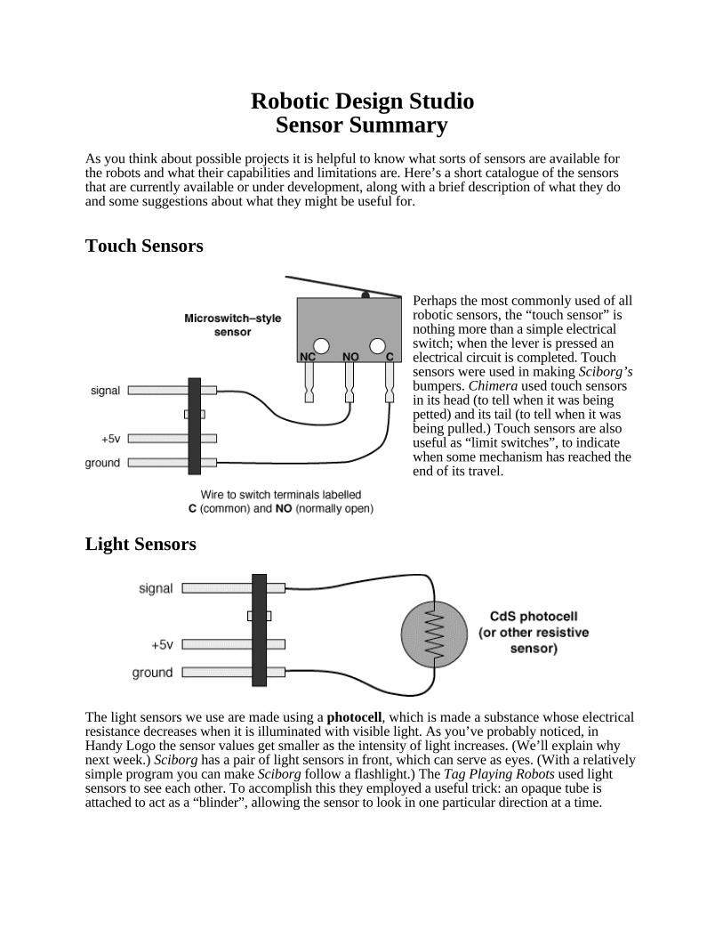
Robotic Design StudioSensor Summary
As you think about possible projects it is helpful to know what sorts of sensors are available forthe robots and what their capabilities and limitations are. Here’s a short catalogue of the sensorsthat are currently available or under development, along with a brief description of what they doand some suggestions about what they might be useful for.
Touch Sensors
Perhaps the most commonly used of allrobotic sensors, the “touch sensor” isnothing more than a simple electricalswitch; when the lever is pressed anelectrical circuit is completed. Touchsensors were used in making Sciborg’sbumpers. Chimera used touch sensorsin its head (to tell when it was beingpetted) and its tail (to tell when it wasbeing pulled.) Touch sensors are alsouseful as “limit switches”, to indicatewhen some mechanism has reached theend of its travel.
Light Sensors
The light sensors we use are made using a photocell, which is made a substance whose electricalresistance decreases when it is illuminated with visible light. As you’ve probably noticed, inHandy Logo the sensor values get smaller as the intensity of light increases. (We’ll explain whynext week.) Sciborg has a pair of light sensors in front, which can serve as eyes. (With a relativelysimple program you can make Sciborg follow a flashlight.) The Tag Playing Robots used lightsensors to see each other. To accomplish this they employed a useful trick: an opaque tube isattached to act as a “blinder”, allowing the sensor to look in one particular direction at a time.
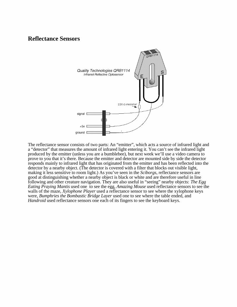
Reflectance Sensors
The reflectance sensor consists of two parts: An “emitter”, which acts a source of infrared light anda “detector” that measures the amount of infrared light entering it. You can’t see the infrared lightproduced by the emitter (unless you are a bumblebee), but next week we’ll use a video camera toprove to you that it’s there. Because the emitter and detector are mounted side by side the detectorresponds mainly to infrared light that has originated from the emitter and has been reflected into thedetector by a nearby object. (The detector is covered with a filter that blocks out visible light,making it less sensitive to room light.) As you’ve seen in the Sciborgs, reflectance sensors aregood at distinguishing whether a nearby object is black or white and are therefore useful in linefollowing and other creature navigation. They are also useful in “seeing” nearby objects: The EggEating Praying Mantis used one to see the egg, Amazing Mouse used reflectance sensors to see thewalls of the maze, Xylophone Player used a reflectance sensor to see where the xylophone keyswere, Bumphries the Bombastic Bridge Layer used one to see where the table ended, andHandroid used reflectance sensors one each of its fingers to see the keyboard keys.
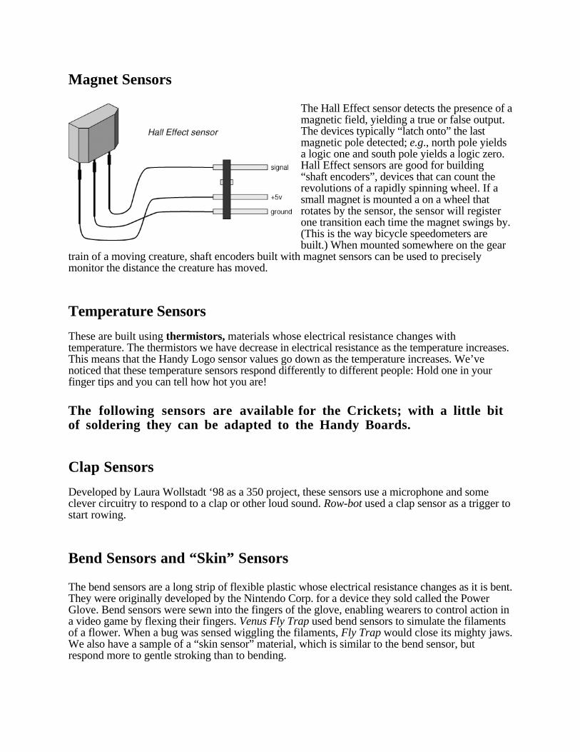
Magnet Sensors
The Hall Effect sensor detects the presence of amagnetic field, yielding a true or false output.The devices typically “latch onto” the lastmagnetic pole detected; e.g., north pole yieldsa logic one and south pole yields a logic zero.Hall Effect sensors are good for building“shaft encoders”, devices that can count therevolutions of a rapidly spinning wheel. If asmall magnet is mounted a on a wheel thatrotates by the sensor, the sensor will registerone transition each time the magnet swings by.(This is the way bicycle speedometers arebuilt.) When mounted somewhere on the gear
train of a moving creature, shaft encoders built with magnet sensors can be used to preciselymonitor the distance the creature has moved.
Temperature Sensors
These are built using thermistors, materials whose electrical resistance changes withtemperature. The thermistors we have decrease in electrical resistance as the temperature increases.This means that the Handy Logo sensor values go down as the temperature increases. We’venoticed that these temperature sensors respond differently to different people: Hold one in yourfinger tips and you can tell how hot you are!
The following sensors are available for the Crickets; with a little bitof soldering they can be adapted to the Handy Boards.
Clap Sensors
Developed by Laura Wollstadt ‘98 as a 350 project, these sensors use a microphone and someclever circuitry to respond to a clap or other loud sound. Row-bot used a clap sensor as a trigger tostart rowing.
Bend Sensors and “Skin” Sensors
The bend sensors are a long strip of flexible plastic whose electrical resistance changes as it is bent.They were originally developed by the Nintendo Corp. for a device they sold called the PowerGlove. Bend sensors were sewn into the fingers of the glove, enabling wearers to control action ina video game by flexing their fingers. Venus Fly Trap used bend sensors to simulate the filamentsof a flower. When a bug was sensed wiggling the filaments, Fly Trap would close its mighty jaws.We also have a sample of a “skin sensor” material, which is similar to the bend sensor, butrespond more to gentle stroking than to bending.
Altimeter
Built by Wellesley student Jelena Madic, the altimeter can sense changes in elevation as small as 2meters.
Heart Monitors
The Heart Monitors are of the type used by athletes to monitor their heart rate. They consist of abelt worn around the chest and a small box of electronics that plugs into the Cricket or HandyBoard. When the belt wearer is within about 1 meter of the box, the Handy Board will be able todetect each time her heart beats. You might want to build a robot that responds to your beatingheart!
The following sensor is currently under development:
Ultrasonic Position Sensor
These work by emitting a short burst of “ultrasound”, sound whose frequency is too high for thehuman ear to hear. The sensor then measures the amount of time it takes for a reflected sound waveto return. Since sound travels at a known rate (about 330 m/s) this time will be proportional to thedistance from the sensor to the object that is causing the reflection. The sensor is good at “seeing”people and can measure their position with an accuracy of a view centimeters. Xylophone Playerused a version of this sensor to tell which note people were standing on. Kate Butler ‘98 iscurrently working on a version of the ultrasonic position sensor that will work directly with theHandy Board.
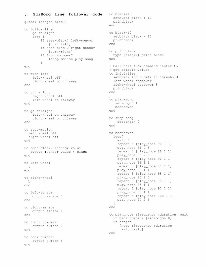
;; SciBorg line follower code
global [songon black]
to follow-line go-straight loop [ if sees-black? left-sensor [turn-left] if sees-black? right-sensor [turn-right] if front-bumper? [stop-motion play-song] ]end
to turn-left left-wheel off right-wheel on thiswayend
to turn-right right-wheel off left-wheel on thiswayend
to go-straight left-wheel on thisway right-wheel on thiswayend
to stop-motion left-wheel off right-wheel offend
to sees-black? :sensor-value output :sensor-value > blackend
to left-wheel a,end
to right-wheel b,end
to left-sensor output sensor 0end
to right-sensor output sensor 1end
to front-bumper? output switch 7end
to back-bumper? output switch 8end
to black+10 setblack black + 10 printblackend
to black-10 setblack black - 10 printblackend
to printblack type [black=] print blackend
; Call this from command center to; get default valuesto initialize setblack 100 ; default threshold left-wheel setpower 8 right-wheel setpower 8 printblackend
to play-song setsongon 1 beethovenend
to stop-song setsongon 0end
to beethoven loop[ wait 6 repeat 3 [play_note 90 1 1] play_note 86 7 5 repeat 3 [play_note 88 1 1] play_note 85 7 5 repeat 3 [play_note 90 1 1] play_note 86 1 1 repeat 3 [play_note 91 1 1] play_note 90 1 1 repeat 3 [play_note 98 1 1] play_note 95 2 5 repeat 3 [play_note 90 1 1] play_note 85 1 1 repeat 3 [play_note 91 1 1] play_note 88 1 1 repeat 3 [play_note 100 1 1] play_note 97 2 5 ]end
to play_note :frequency :duration :wait if back-bumper? [setsongon 0] if songon [note :frequency :duration wait :wait]end
The Handy Logo Language Reference
Fred Martin and Brian SilvermanMIT Media Laboratory�
January 12, 1996
The Handy Board is a hand-held, battery-powered computer that can receiveinputs from electronic sensors (including touch, light, and sound sensors) and op-erate DC motors. It is designed for a variety of educational robotics uses, includingmobile robot projects, data-taking applications, and “ubiquitous computing” ap-plications (projects that embed computers in the world around us).
This document explains how to use the Handy Logo programming language,assuming the Handy Logo version dated January 12, 1996.
�20 Ames Street Room E15–320, Cambridge, MA 02139. The Handy Board hardware was de-signed primarily by Fred Martin; the Handy Logo software system was designed primarily by BrianSilverman. To contact the authors: [email protected] and [email protected]
i
Contents
1 Handy Logo Interface 1
2 Motor Outputs 2
3 Sensor Inputs 3
4 Control Structures 3
5 User Input/Output 45.1 Printing : : : : : : : : : : : : : : : : : : : : : : : : : : : : : : 45.2 Input : : : : : : : : : : : : : : : : : : : : : : : : : : : : : : : : 55.3 Sound : : : : : : : : : : : : : : : : : : : : : : : : : : : : : : : 55.4 Infrared Communication : : : : : : : : : : : : : : : : : : : : : : 5
6 Serial Line 6
7 Multi-Tasking 67.1 Starting Processes : : : : : : : : : : : : : : : : : : : : : : : : : 77.2 Stopping Processes : : : : : : : : : : : : : : : : : : : : : : : : : 77.3 Process Granularity : : : : : : : : : : : : : : : : : : : : : : : : 9
8 Data Recording and Playback 9
9 Procedures, Variables, and Comments 109.1 Procedure Definition : : : : : : : : : : : : : : : : : : : : : : : : 109.2 Procedure Inputs : : : : : : : : : : : : : : : : : : : : : : : : : : 109.3 Local Variables : : : : : : : : : : : : : : : : : : : : : : : : : : 109.4 Global Variables : : : : : : : : : : : : : : : : : : : : : : : : : : 119.5 Procedure Return Values : : : : : : : : : : : : : : : : : : : : : : 119.6 Code Comments : : : : : : : : : : : : : : : : : : : : : : : : : : 12
10 Numeric Operations 1210.1 Arithmetic Operators : : : : : : : : : : : : : : : : : : : : : : : : 1210.2 Boolean and Bitwise Operators : : : : : : : : : : : : : : : : : : 1310.3 Precedence : : : : : : : : : : : : : : : : : : : : : : : : : : : : : 1310.4 Random Numbers : : : : : : : : : : : : : : : : : : : : : : : : : 13
ii

11 Memory Access 14
12 File Management 14
iii
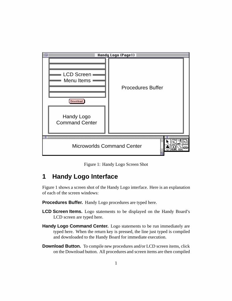
Procedures Buffer
Handy LogoCommand Center
Microworlds Command Center
LCD ScreenMenu Items
Figure 1: Handy Logo Screen Shot
1 Handy Logo Interface
Figure 1 shows a screen shot of the Handy Logo interface. Here is an explanationof each of the screen windows:
Procedures Buffer. Handy Logo procedures are typed here.
LCD Screen Items. Logo statements to be displayed on the Handy Board’sLCD screen are typed here.
Handy Logo Command Center. Logo statements to be run immediately aretyped here. When the return key is pressed, the line just typed is compiledand downloaded to the Handy Board for immediate execution.
Download Button. To compile new procedures and/or LCD screen items, clickon the Download button. All procedures and screen items are then compiled
1
and downloaded to the Handy Board.
Microworlds Command Center. Instructions to be given to the underlyingMicroworlds Logo interpreter are typed here.
2 Motor Outputs
Motors are labelled on the Handy Board itself as Motor-0, Motor-1, Motor-2, andMotor-3, but are referred to in Handy Logo by letter, with “a” being Motor-0, “b”being Motor-1, etc.
Each motor output is capable of bidirectional control of a DC motor, at eightsteps of power from off to full on.
a, Selects motor A for subsequent commands.
b, Selects motor B.
c, Selects motor C.
d, Selects motor D.
ab, Selects motors A and B together.
bc, Selects motors B and C.
ac, Selects motors A and C.
ad, Selects motors A and D.
abcd, Selects all motors.
on Turns selected motor(s) on.
off Turns selected motor(s) off.
toggle Inverts on/off state of selected motor(s); i.e., motors that are off go on,and motors that are on go off.
rd Reverses direction of selected motor(s).
thisway Sets selected motor(s) for one of the two possible directions (indicatedby the green motor LED being illuminated). When motors are first turnedon, they are in the “thisway” state.
2
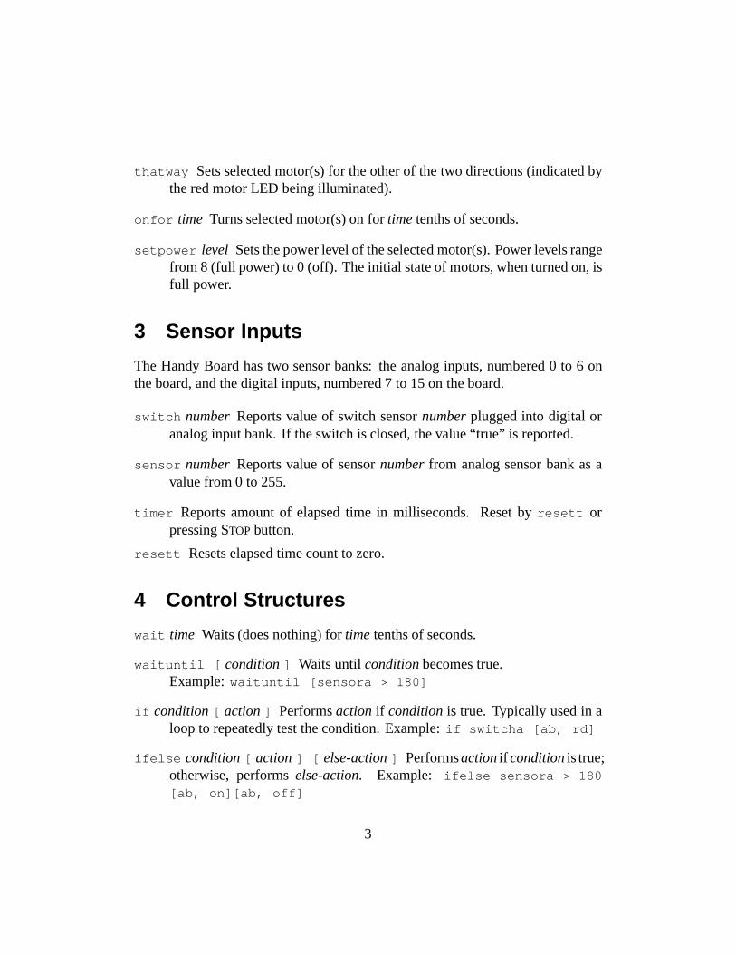
thatway Sets selected motor(s) for the other of the two directions (indicated bythe red motor LED being illuminated).
onfor time Turns selected motor(s) on for time tenths of seconds.
setpower level Sets the power level of the selected motor(s). Power levels rangefrom 8 (full power) to 0 (off). The initial state of motors, when turned on, isfull power.
3 Sensor Inputs
The Handy Board has two sensor banks: the analog inputs, numbered 0 to 6 onthe board, and the digital inputs, numbered 7 to 15 on the board.
switch number Reports value of switch sensor number plugged into digital oranalog input bank. If the switch is closed, the value “true” is reported.
sensor number Reports value of sensor number from analog sensor bank as avalue from 0 to 255.
timer Reports amount of elapsed time in milliseconds. Reset by resett orpressing STOP button.
resett Resets elapsed time count to zero.
4 Control Structures
wait time Waits (does nothing) for time tenths of seconds.
waituntil [ condition ] Waits until condition becomes true.Example: waituntil [sensora > 180]
if condition [ action ] Performs action if condition is true. Typically used in aloop to repeatedly test the condition. Example: if switcha [ab, rd]
ifelse condition [ action ] [ else-action ] Performs action if condition is true;otherwise, performs else-action. Example: ifelse sensora > 180[ab, on][ab, off]
3
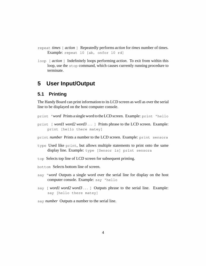
repeat times [ action ] Repeatedly performs action for times number of times.Example: repeat 10 [ab, onfor 10 rd]
loop [ action ] Indefinitely loops performing action. To exit from within thisloop, use the stop command, which causes currently running procedure toterminate.
5 User Input/Output
5.1 Printing
The Handy Board can print information to its LCD screen as well as over the serialline to be displayed on the host computer console.
print "word Prints a single word to the LCD screen. Example: print "hello
print [ word1 word2 word3 : : : ] Prints phrase to the LCD screen. Example:print [hello there matey]
print number Prints a number to the LCD screen. Example: print sensora
type Used like print, but allows multiple statements to print onto the samedisplay line. Example: type [Sensor is] print sensora
top Selects top line of LCD screen for subsequent printing.
bottom Selects bottom line of screen.
say "word Outputs a single word over the serial line for display on the hostcomputer console. Example: say "hello
say [ word1 word2 word3 : : : ] Outputs phrase to the serial line. Example:say [hello there matey]
say number Outputs a number to the serial line.
4
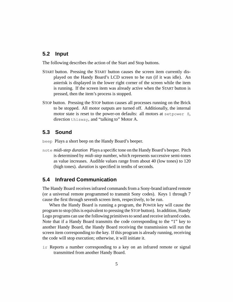
5.2 Input
The following describes the action of the Start and Stop buttons.
START button. Pressing the START button causes the screen item currently dis-played on the Handy Board’s LCD screen to be run (if it was idle). Anasterisk is displayed in the lower right corner of the screen while the itemis running. If the screen item was already active when the START button ispressed, then the item’s process is stopped.
STOP button. Pressing the STOP button causes all processes running on the Brickto be stopped. All motor outputs are turned off. Additionally, the internalmotor state is reset to the power-on defaults: all motors at setpower 8,direction thisway, and “talking to” Motor A.
5.3 Sound
beep Plays a short beep on the Handy Board’s beeper.
note midi-step duration Plays a specific tone on the Handy Board’s beeper. Pitchis determined by midi-step number, which represents successive semi-tonesas value increases. Audible values range from about 40 (low tones) to 120(high tones). duration is specified in tenths of seconds.
5.4 Infrared Communication
The Handy Board receives infrared commands from a Sony-brand infrared remote(or a universal remote programmed to transmit Sony codes). Keys 1 through 7cause the first through seventh screen item, respectively, to be run.
When the Handy Board is running a program, the POWER key will cause theprogram to stop (this is equivalent to pressing the STOP button). In addition, HandyLogo programs can use the following primitives to send and receive infrared codes.Note that if a Handy Board transmits the code corresponding to the “1” key toanother Handy Board, the Handy Board receiving the transmission will run thescreen item corresponding to the key. If this program is already running, receivingthe code will stop execution; otherwise, it will initiate it.
ir Reports a number corresponding to a key on an infrared remote or signaltransmitted from another Handy Board.
5
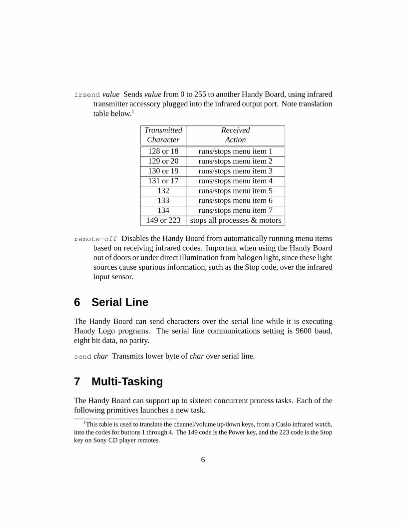
irsend value Sends value from 0 to 255 to another Handy Board, using infraredtransmitter accessory plugged into the infrared output port. Note translationtable below.1
Transmitted ReceivedCharacter Action
128 or 18 runs/stops menu item 1129 or 20 runs/stops menu item 2130 or 19 runs/stops menu item 3131 or 17 runs/stops menu item 4
132 runs/stops menu item 5133 runs/stops menu item 6134 runs/stops menu item 7
149 or 223 stops all processes & motors
remote-off Disables the Handy Board from automatically running menu itemsbased on receiving infrared codes. Important when using the Handy Boardout of doors or under direct illumination from halogen light, since these lightsources cause spurious information, such as the Stop code, over the infraredinput sensor.
6 Serial Line
The Handy Board can send characters over the serial line while it is executingHandy Logo programs. The serial line communications setting is 9600 baud,eight bit data, no parity.
send char Transmits lower byte of char over serial line.
7 Multi-Tasking
The Handy Board can support up to sixteen concurrent process tasks. Each of thefollowing primitives launches a new task.
1This table is used to translate the channel/volume up/down keys, from a Casio infrared watch,into the codes for buttons 1 through 4. The 149 code is the Power key, and the 223 code is the Stopkey on Sony CD player remotes.
6
7.1 Starting Processes
launch [ action ] Launches action as a separate process, and starts a new pro-cess family (see Section 7.2, below).
forever [ action ] Launches a process to repeatedly execute action.
when [ condition ][ action ] Launches a process to repeatedly test conditionand execute action when it becomes true.
The condition clause for the when statement fires on edge-triggered logic;that is, action is run once for each time the condition changes from falseto true. In the case in which the condition is true the first time the whenstatement is executed, the action is not run.
every time [ action ] Launches a process to execute action every time tenths-of-seconds.
7.2 Stopping Processes
Pressing the STOP button or sending the infrared stop code stops all running tasks,turns off motors, and resets the internal motor state (see 5.2).
Additionally, the “stoprules” primitive may be used for process control. stop-rules kills all processes begun in the current process family. A new processfamily is formed every time the launch primitive occurs, when a command isstarted in the command center, and when a command is started from a menu item.stoprules does not terminate execution of the procedure that calls it.
Here are two examples. In the first, a procedure launches an every process(“mode 1”), waits for a trigger condition, uses stoprules to halt this, and thenlaunches a new every process (“mode 2”):
to mode1thenmode2a, every 10 [onfor 2] ; mode 1waituntil [switch 0] ; trigger for mode 2stoprulesb, every 10 [onfor 2] ; mode 2
end
7
The mode1thenmode2 procedure consists of one launch family; after thestoprules command, mode 1 is halted and mode 2 is launched.
The second example is more sophisticated because it demonstrates how modesmay be both stopped and restarted. The main procedure launches two processfamilies (mode1-control and mode2-control) which take care of starting andstopping themselves based on different conditions:
to mainlaunch [mode1-control]launch [mode2-control]
end
to mode1-controlloop [waituntil [starting-condition]
mode1 ; begin mode1 taskswaituntil [stopping-condition]stoprules ; stop mode1 tasks
]end
to mode2-control(same form as mode1-control)
end
to mode1(mode1 when’s, every’s, and forever’s)
end
to mode2(mode2 when’s, every’s, and forever’s)
end
In the example, the two modes are responsible for starting and stopping them-selves (though this happens asynchronously). If it were desirable to have a thirdprocess control the other two, this should be done by having the third processset global variables that the other processes examine to enable and disable theiractivity (see comments at Section 7.3).
8
stoprules Stops all processes in the current process family. Has no effect whenissued from the command center.
7.3 Process Granularity
Handy Logo allows each process to evaluate one Logo statement per time slice.A Logo statement is defined as a piece of Logo code that does not return a value.For example, each of the following is an individual Logo statement and will fullyexecute in one time slice:
ononfor 10onfor 3 + sensor 5setfoo digital 3 (assumes foo is declared as a global)if not foo [setfoo 1] (assumes foo is declared as a global)
As indicated by the final example, this time-slicing protocol allows HandyLogo to support semaphors for dynamic process interaction. The semaphor istypically used to coordinate shared control of a resource. A global variableindicates whether the resource is free; if it is, a process then sets the global toindicate that it has taken control of the resource. It is necessary for this “test andset” operation—the semaphor—to happen in a single time slice, so that a processdoes not perform the test, get swapped out, and then return to take control of aresource that has been grabbed in its absence. The final example shows how thetest-and-set operation should be performed in Handy Logo.
8 Data Recording and Playback
There is a single global array for storing data which holds 16,382 2-byte integervalues. There is no error-checking to prevent against overrunning the data buffer.
erase Resets the data recording pointer to zero.
record value Records value in the data buffer, and advances the recordingpointer.
record# Reports value of record pointer, indicating where the next data point tobe recorded will go.
9
resetr Resets the recall pointer to zero.
recall Reports value of current data point, and advances the recall pointer.
recall# Reports value of recall pointer.
9 Procedures, Variables, and Comments
9.1 Procedure Definition
Procedures are defined using the keyword “to”; i.e.:
to testprocedure body
end
9.2 Procedure Inputs
Inputs, or arguments, to procedures are declared using the standard Logo colonsyntax; e.g.:
to test :input1 :input2top type [Input 1 is] print :input1bottom type [Input 2 is] print :input2wait 10
end
Procedure inputs are local variables.
9.3 Local Variables
Local variables are declared using the let keyword, accessed using Logo’s colonsyntax, and set using the make keyword:
to local-examplelet [alocal 5 anotherlocal 17]print :alocal ; prints "5"
10
make "anotherlocal 3print :anotherlocal ; prints "3"
end
The “let” declaration should be made at the beginning of a procedure.
9.4 Global Variables
Global variables are declared using the global keyword, which takes a list of thenames of globals to be created; i.e.:
global [name1 name2 name3 : : :]
This declaration should come at the beginning of the procedure buffer. Afterbeing declared, each global is set using a mechanism in which the global name ispreceded by the word “set.” Global values are accessed by using the global nameas a reporter; e.g.:
global [myglobal]
to testsetmyglobal 3print myglobalwait 10
end
Global variables maintain their value when the Handy Board is power-cycled.
9.5 Procedure Return Values
By default, procedures do not produce return values. Procedures may return anumeric value using the output primitive; e.g.:
to double :noutput :n * 2
end
11

Procedures may terminate at any point using the stop primitive, which exitsthe procedure without producing a return value.
Care should be taken to ensure that a procedure either always or never exitswith a return value.
9.6 Code Comments
There are two forms for comments in the procedure buffer:
� Any text between the end statement of one procedure and the to declarationof the next procedure is ignored.
� Any text after a semicolon (“;”) on any given line is ignored.
10 Numeric Operations
Handy Logo is based on signed 16-bit integer arithmetic (all numeric values arein the inclusive range from �32768 to +32767).
All of the following arithmetic and boolean operators must be preceded andfollowed by a space. For example, the following expression is not legitimate:
print 3+4 ; this does not work
10.1 Arithmetic Operators
The following arithmetic operators are supported, using infix notation:
+ — addition.
- — subtraction.
* — multiplication.
/ — division.
n — remainder.
The minus sign may also be used as a prefix negation operator.
12
10.2 Boolean and Bitwise Operators
The Boolean operators always produce values of zero or one. In evaluatingconditionals, zero is false; any value other than zero is true.
and — performs bitwise “and” function. Prefix.
or — performs bitwise “or” function. Prefix.
not — performs Boolean logical negation. Prefix.
> — performs Boolean test for greater-than. Infix.
< — performs Boolean test for less-than. Infix.
= — performs Boolean test for equality. Infix.
Since the Boolean operators produce values of one and zero, and non-zeroresults are considered true, the and and or operators, which are bitwise, can func-tion as Booleans when combining the result of other conditionals. The followingexample illustrates correct usage:
if and (:value > 100) (:value < 150) [doit]
10.3 Precedence
Order of evaluation is from left to right; standard rules of precedence are notobserved. Parentheses may be used to override the standard order of evaluation.
10.4 Random Numbers
Handy Logo includes a primitive for generating pseudo-random numbers. The“random” primitive takes as input the upper limit of the number to be generated,and reports a value between 0 and that number minus 1 (inclusive).
Random’s operation is based on a 2 MHz system clock inside the 6811 CPU.When random is called, the clock is sampled and the modulus of the low bits andthe input to random is returned.
random limit Reports a pseudo-random number between 0 and limit � 1 (inclu-sive).
13
11 Memory Access
Four primitives exist for directly accessing system memory.
eb address Examine Byte. Reports the byte located at memory address as a valuefrom 0 to 255.
ew address Examine Word. Reports the 16-bit value located at memory address.
db address value Deposit Byte. Stores the lower byte of value at memory address.
dw address value Deposit Word. Stores value at memory address.
12 File Management
To save and load Handy Logo programs, please use the following (rather thansaving multiple copies of the Handy Logo project file):
saveall "filename Saves procedures and screen items into file named filename.
loadall "filename Loads procedures and screen items from file named file-name.
These commands must be typed into the Microworlds command center, locatedat the bottom of the computer screen, not the Handy Board command center.
14

page 1
Cricket Logo Language Reference"Blue Dot" Version
Cricket Logo was designed and implemented by Brian Silverman with help from Fred Martin andRobbie Berg. This language reference was written by Fred Martin and Robbie Berg. A less technicalintroduction can be found in the document Getting Started With Crickets1. For more information aboutCrickets visit the Cricket Home Page on the World Wide Web at:
http://lcs.www.media.mit.edu/people/fredm/projects/cricket/
1. Overview
Cricket Logo has the following features:
• control structures like if , repeat , wait , waituntil and loop• motor and sensor primitives• global and local variables• global arrays• procedure definition with inputs and return values• primitives for infrared communication• a mulitasking when primitive• a 16-bit number system (addition, subtraction, multiplication, division, comparison);• timing functions, a tone-playing function, and a random number function• data recording and playback primitives
1 Crickets are part of an ongoing research project carried out by:
The Epistemology and Learning GroupMIT Media Laboratory20 Ames Street Cambridge, MA 02139
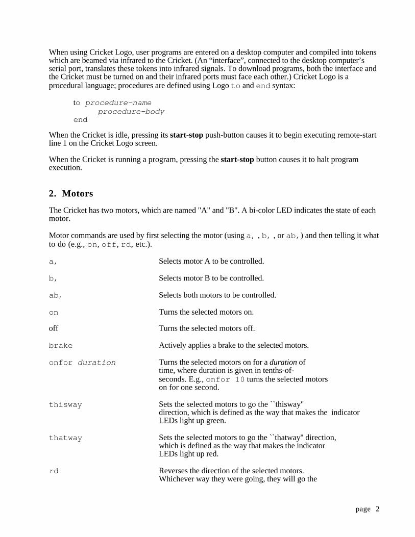
page 2
When using Cricket Logo, user programs are entered on a desktop computer and compiled into tokenswhich are beamed via infrared to the Cricket. (An “interface”, connected to the desktop computer’sserial port, translates these tokens into infrared signals. To download programs, both the interface andthe Cricket must be turned on and their infrared ports must face each other.) Cricket Logo is aprocedural language; procedures are defined using Logo to and end syntax:
to procedure-nameprocedure-body
end
When the Cricket is idle, pressing its start-stop push-button causes it to begin executing remote-startline 1 on the Cricket Logo screen.
When the Cricket is running a program, pressing the start-stop button causes it to halt programexecution.
2. Motors
The Cricket has two motors, which are named "A" and "B". A bi-color LED indicates the state of eachmotor.
Motor commands are used by first selecting the motor (using a, , b, , or ab, ) and then telling it whatto do (e.g., on , off , rd , etc.).
a, Selects motor A to be controlled.
b, Selects motor B to be controlled.
ab, Selects both motors to be controlled.
on Turns the selected motors on.
off Turns the selected motors off.
brake Actively applies a brake to the selected motors.
onfor duration Turns the selected motors on for a duration oftime, where duration is given in tenths-of-seconds. E.g., onfor 10 turns the selected motorson for one second.
thisway Sets the selected motors to go the ``thisway''direction, which is defined as the way that makes the indicatorLEDs light up green.
thatway Sets the selected motors to go the ``thatway'' direction,which is defined as the way that makes the indicatorLEDs light up red.
rd Reverses the direction of the selected motors.Whichever way they were going, they will go the
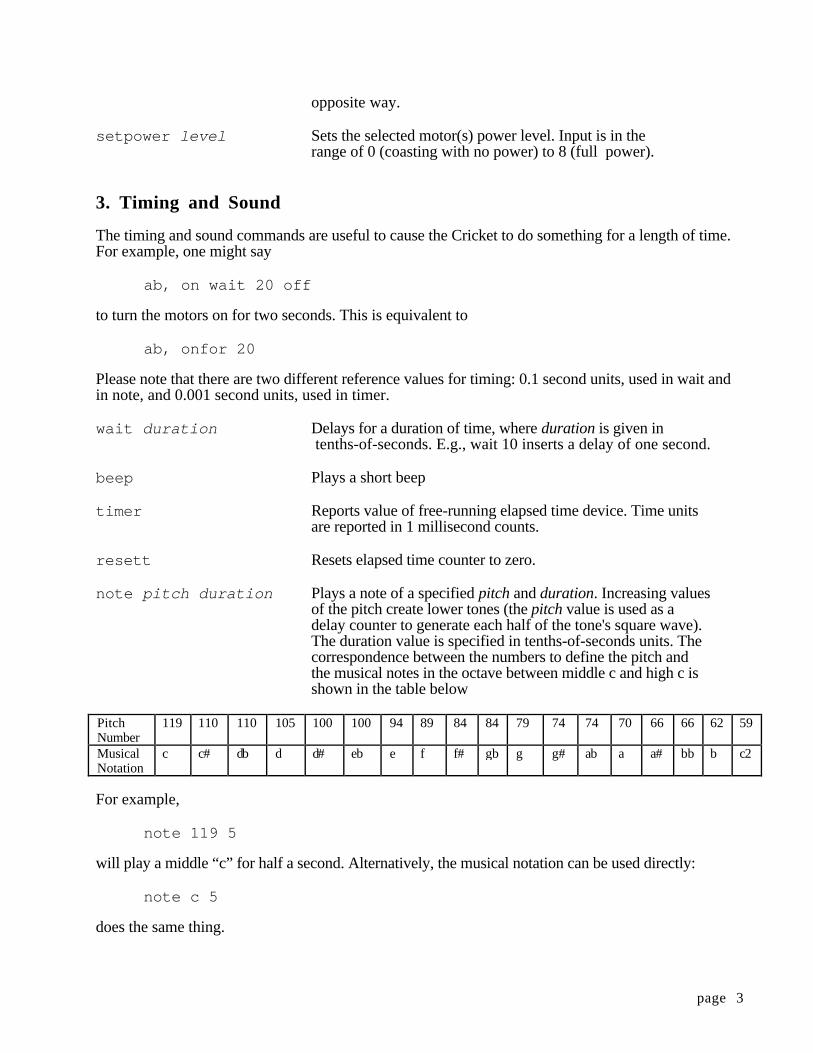
page 3
opposite way.
setpower level Sets the selected motor(s) power level. Input is in therange of 0 (coasting with no power) to 8 (full power).
3. Timing and Sound
The timing and sound commands are useful to cause the Cricket to do something for a length of time.For example, one might say
ab, on wait 20 off
to turn the motors on for two seconds. This is equivalent to
ab, onfor 20
Please note that there are two different reference values for timing: 0.1 second units, used in wait andin note, and 0.001 second units, used in timer.
wait duration Delays for a duration of time, where duration is given in tenths-of-seconds. E.g., wait 10 inserts a delay of one second.
beep Plays a short beep
timer Reports value of free-running elapsed time device. Time unitsare reported in 1 millisecond counts.
resett Resets elapsed time counter to zero.
note pitch duration Plays a note of a specified pitch and duration. Increasing valuesof the pitch create lower tones (the pitch value is used as adelay counter to generate each half of the tone's square wave).The duration value is specified in tenths-of-seconds units. Thecorrespondence between the numbers to define the pitch andthe musical notes in the octave between middle c and high c isshown in the table below
PitchNumber
119 110 110 105 100 100 94 89 84 84 79 74 74 70 66 66 62 59
MusicalNotation
c c# db d d# eb e f f# gb g g# ab a a# bb b c2
For example,
note 119 5
will play a middle “c” for half a second. Alternatively, the musical notation can be used directly:
note c 5
does the same thing.
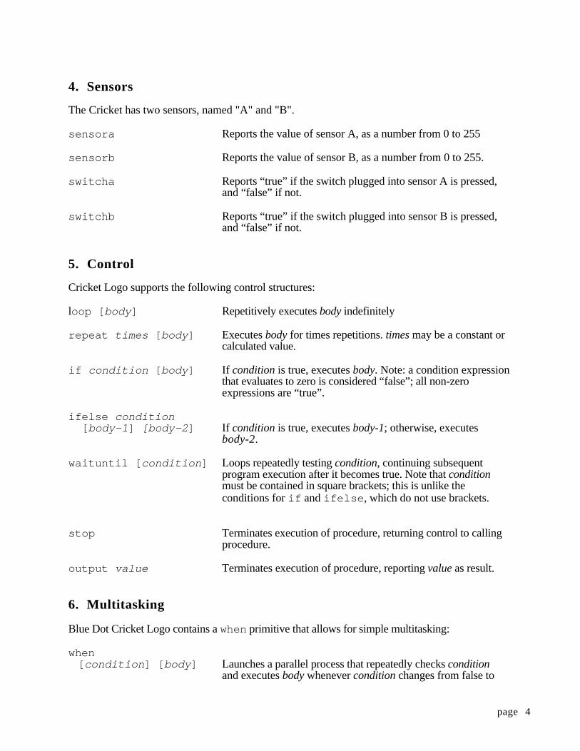
page 4
4. Sensors
The Cricket has two sensors, named "A" and "B".
sensora Reports the value of sensor A, as a number from 0 to 255
sensorb Reports the value of sensor B, as a number from 0 to 255.
switcha Reports “true” if the switch plugged into sensor A is pressed,and “false” if not.
switchb Reports “true” if the switch plugged into sensor B is pressed,and “false” if not.
5. Control
Cricket Logo supports the following control structures:
loop [ body ] Repetitively executes body indefinitely
repeat times [ body ] Executes body for times repetitions. times may be a constant orcalculated value.
if condition [ body ] If condition is true, executes body. Note: a condition expressionthat evaluates to zero is considered “false”; all non-zeroexpressions are “true”.
ifelse condition [ body-1 ] [body-2 ] If condition is true, executes body-1; otherwise, executes
body-2.
waituntil [ condition ] Loops repeatedly testing condition, continuing subsequentprogram execution after it becomes true. Note that conditionmust be contained in square brackets; this is unlike theconditions for if and ifelse , which do not use brackets.
stop Terminates execution of procedure, returning control to calling procedure.
output value Terminates execution of procedure, reporting value as result.
6. Multitasking
Blue Dot Cricket Logo contains a when primitive that allows for simple multitasking:
when [ condition ] [ body ] Launches a parallel process that repeatedly checks condition
and executes body whenever condition changes from false to
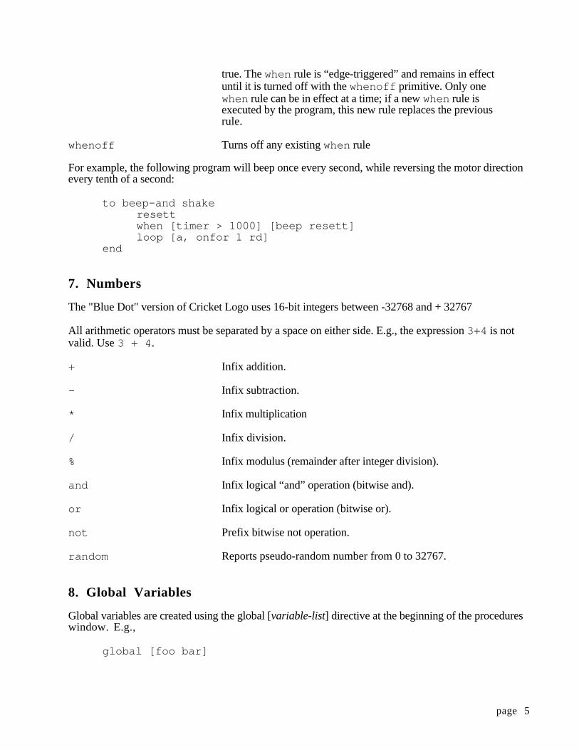
page 5
true. The when rule is “edge-triggered” and remains in effectuntil it is turned off with the whenoff primitive. Only onewhen rule can be in effect at a time; if a new when rule isexecuted by the program, this new rule replaces the previousrule.
whenoff Turns off any existing when rule
For example, the following program will beep once every second, while reversing the motor directionevery tenth of a second:
to beep-and shakeresettwhen [timer > 1000] [beep resett]loop [a, onfor 1 rd]
end
7. Numbers
The "Blue Dot" version of Cricket Logo uses 16-bit integers between -32768 and + 32767
All arithmetic operators must be separated by a space on either side. E.g., the expression 3+4 is notvalid. Use 3 + 4 .
+ Infix addition.
- Infix subtraction.
* Infix multiplication
/ Infix division.
% Infix modulus (remainder after integer division).
and Infix logical “and” operation (bitwise and).
or Infix logical or operation (bitwise or).
not Prefix bitwise not operation.
random Reports pseudo-random number from 0 to 32767.
8. Global Variables
Global variables are created using the global [variable-list] directive at the beginning of the procedureswindow. E.g.,
global [foo bar]
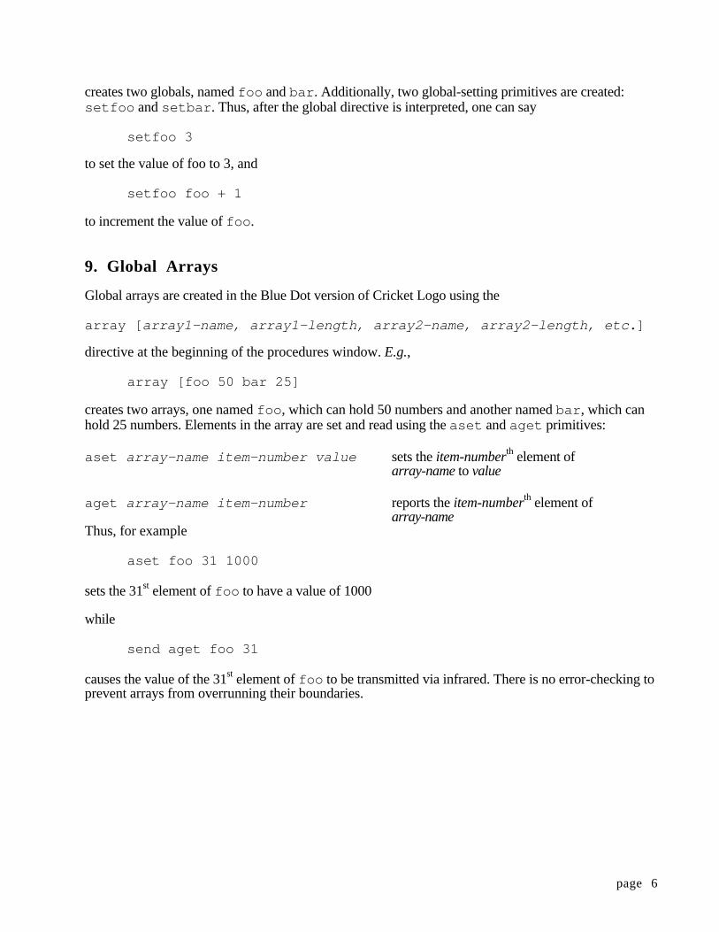
page 6
creates two globals, named foo and bar . Additionally, two global-setting primitives are created:setfoo and setbar . Thus, after the global directive is interpreted, one can say
setfoo 3
to set the value of foo to 3, and
setfoo foo + 1
to increment the value of foo .
9. Global Arrays
Global arrays are created in the Blue Dot version of Cricket Logo using the
array [ array1-name, array1-length, array2-name, array2-length, etc. ]
directive at the beginning of the procedures window. E.g.,
array [foo 50 bar 25]
creates two arrays, one named foo , which can hold 50 numbers and another named bar , which canhold 25 numbers. Elements in the array are set and read using the aset and aget primitives:
aset array-name item-number value sets the item-numberth element ofarray-name to value
aget array-name item-number reports the item-numberth element ofarray-name
Thus, for example
aset foo 31 1000
sets the 31st element of foo to have a value of 1000
while
send aget foo 31
causes the value of the 31st element of foo to be transmitted via infrared. There is no error-checking toprevent arrays from overrunning their boundaries.
page 7
10. Procedure Inputs and Outputs
Procedures can accept arguments using Logo’s colon syntax. E.g.,
to wiggle :timesab,repeat :times [on wait 2 rd]
end
creates a procedure named wiggle that takes an input which is used as the counter in a repeat loop.
Procedures may return values using the output primitive; e.g.:
to goab,repeat third [on wait 10 rd]
end
to thirdif sensora < 20 [output 1]if sensora < 50 [output 2]output 3
end
The go procedure will execute 1, 2, or 3 times depending on the value of sensor A.
11. Data Recording and Playback
In addition to the user defined arrays mentioned above there is a single global array for storing datawhich holds 1024 one-byte numbers. There is no error checking to prevent overrunning the databuffer. The following primitives are available for data recording and playback:
setdp number Sets the value of the data pointer.
record value Records value in the data buffer and advances the data pointer.
recall value Reports the value of the current data point and advances thedata pointer.
erase Sets the value of all 1024 elements of the data array to zero and then sets the data pointer to zero. Because the process ofrecording data is relatively slow (about 20 milliseconds per datapoint) it takes about 20 seconds for the erase command to beexecuted
For example the procedure take-data can be used to store data recorded by a sensor once everysecond:
page 8
to take-dataerase beeprepeat 1024 [record sensora wait 10]
end
The data can be "replayed" using the following send-data procedure:
to send-datasetdp 0repeat 1024 [send recall wait 5]
end
This causes the data to appear in the monitor box on the Cricket Logo screen on the desktop, updatingtwice a second. The Cricket Logo desktop also contains built-in graphing capabilities for rapidlyuploading, graphing, and analyzing data.
12. Recursion
Cricket Logo supports tail recursion to create infinite loops. For example:
to beep-foreverbeep wait 1beep-forever
end
is equivalent to
to beep-foreverloop [beep wait 1]
end
The recursive call must appear as the last line of the procedure and cannot be part of a control structurelike if or waituntil . Thus the following is not valid:
to beep-when-pressedbeep wait 1if switcha [beep-when-pressed]
end
13. Infrared Communication
Crickets can send infrared signals to each other using the send primitive, and receive them using their primitive. The newir? primitive can be used to check if a new infrared signal has beenreceivedsince the last time newir? primitive was used send value transmits value via infrared.
ir reports the byte most recently received by the infrared detector. Notethat the Blue Dot crickets do not clear the infrared buffer. Thus the irprimitive reports the most recent byte received.
page 9
newir? reports “true” if a new byte has been received by the infrared detectorsince last time newir? was used, and “false” if not. It does not effectthe contents of the infrared buffer. For example, consider the followinguse of the newir? primitive:
to thing1-or-thing2waituntil [newir?] ;checks for new infrared byte if ir = 1 [thing1]if ir = 2 [thing2]
end
to thing1 . . . end
to thing2 . . . end
In this example nothing happens until a new infrared byte is received. There are cases when you may want to use an alternate form of the thing1-or-thing2 procedure:
to thing1-or-thing2 if newir? ;checks for new infrared byte
[if ir = 1 [thing1]if ir = 2 [thing2]]
end
In this case we do not wish to hold everything up until a new infrared byte is received; we only wantthing1 or thing2 to happen if a new infrared byte is received.
Infrared codes in the range 128 to129 are interpreted to launch remote-start menu items 1 or 2 on thecricket logo screen. These codes can be generated by pressing buttons #1 or #2 on the interfacerespectively. Household TV/VCR remotes may be used to cause the cricket to launch its two remote-start lines. Use a sony remote, or a universal remote set to talk to a Sony TV, and use the keysnumbered 1 and 2.
Infrared codes in the range 130 to 140 are used by the underlying cricket operating system as escapecodes for infrared program download. Therefore please restrict general purpose user broadcast of ircodes to the ranges of 1 to 127 or 141 and above.
Received infrared values issued with the send primitive are displayed on the cricket logo screen in thesmall text box next to the download button.
page 10
14. Other Details
If a Cricket is not running a program (which is indicated by the green run light being off), infraredcodes from 128 to 129 are interpreted to launch remote-start menu items 1 or 2 on the Cricket Logoscreen. These codes can be generated by pressing buttons #1 or #2 on the interface respectively.Household TV/VCR remotes may also be used to cause the Cricket to launch its two remote-start lines.Use a Sony remote, or a universal remote set to talk to a Sony TV, and use the keys numbered 1 and2.
Infrared codes in the range of 130 and higher are used by the underlying Cricket operating system asescape codes for infrared program download. Therefore please restrict general purpose user broadcastof IR codes to the range of 1 to 127.
Received infrared values issued with the send primitive are displayed on the Cricket Logo screen in thesmall text box next to the download button.
Caveats:
The maximum size of a Cricket Logo program is 768 bytes. (This number becomes smaller if arraysare used. Each array element takes up two bytes of memory. If the record primitive is not used,programs as long as 1792 bytes are possible.) In addition, a maximum of 16 different global variablesmay be used.
When a program is downloaded, its size is displayed in the “status box” near the bottom of the CricketLogo procedures window.
15. Two Sample Programs
Dancing Crickets
Here's a simple program written by two 10 year old boys who had seen the "dancing Crickets" andwanted to build their own (single Cricket) version:
to dancecha-cha-chago-roundshake-it
end
to cha-cha-charepeat 4 [back-and-forth]ab, off
end
to back-and-forthab, thisway onfor 3beepab, thatway onfor 3beep
end
to go-round
page 11
a, on thiswayb, on thatwaybeep wait 1 beep wait 1 beepwait 60ab, off
end
to shake-ita, thiswayb, thatwayab,repeat 10 [beep onfor 1 beep rd onfor 1 rd]
end
Note that these kids made their program easier to follow by nesting procedures inside of otherprocedures. For example, the procedure dance calls the procedure cha-cha-cha, which in turncalls back-and-forth .
The Wandering LEGObug
The LEGObug is a creature with two motors connected to its two rear wheels. It also has two touchsensors connected to two "whiskers" positioned on either sides of its head and two light sensors thatserve as "eyes." Detailed plans for building the LEGObug are available at the following URL:
http://lc s.www.media.mit.edu/people/fredm/projects/legobug/
The procedure seek shown below causes the creature to be attracted to bright light. It assumes that thelight sensors are plugged into the Cricket's sensor-ports. The light sensors have the property that thegreater the amount of light that hits them, the smaller the sensor value that is produced. (In typicalindoor lighting the light sensors might give readings in the 15 - 30 range, if you shine a flashlight onthem, they will produce a reading in the 1 - 5 range. It takes almost complete darkness to produce areading of 255.)
to seekloop [
ifelse (sensora < 10) or (sensorb < 10)[go-forward][stop-motors]
]end
;the motors are each hooked up so that the "thisway" ;directioncauses them to drive forward
to go-forwardab, on thisway
end
to stop-motorsab, off
end
page 12
As an exercise you might try making creatures that run away from the dark, or ones that turn toward abright light.
The procedure wander shown below causes LEGObug to drive straight until a whisker bumps into anobstacle. (It assumes that the touch sensors are plugged into the two sensor-ports.) In an attempt toavoid the obstacle, it the creature backs up a bit, turns a small (random) amount and continues to driveforward.
to wandergo-forwardwaituntil [touch-left? or touch-right?]ifelse touch-left?[back-up turn-right][back-up turn-left]wander
end
to go-forwardab, on thisway
end
;touch-left reports "true" if the sensor;plugged into sensor-port "a" is pressed
to touch-left?output switcha
end
;touch-left reports "true" if the sensor;plugged into sensor-port "a" is pressed
to touch-right?output switchb
end
;turns right for a random amount of time between 0 and 5;seconds.;the primitive random reports a random number between 0 and 255
to turn-rightb, off 5a, thisway onfor (random / 5)
end
to turn-lefta, offb, thisway onfor (random / 5)
end
to back-upab, thatway onfor 20end

page 13
For more information about Crickets visit the Cricket Home Page on the World Wide Web at:
http://lcs.www.media.mit.edu/people/fredm/projects/cricket/
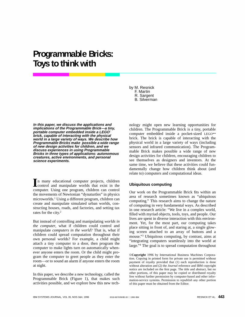
443
©Copyright 1996 by International Business Machines Corpora-tion. Copying in printed form for private use is permitted withoutpayment of royalty provided that (1) each reproduction is donewithout alteration and (2) theJournal reference and IBM copyrightnotice are included on the first page. The title and abstract, but noother portions, of this paper may be copied or distributed royaltyfree without further permission by computer-based and other infor-mation-service systems. Permission torepublish any other portionof this paper must be obtained from the Editor.
IBM SYSTEMS JOURNAL, VOL 35, NOS 3&4, 1996 0018-8670/96/$5.00 1996 IBM RESNICK ET AL.
In this paper, we discuss the applications andimplications of the Programmable Brick—a tiny,portable computer embedded inside a LEGO
brick, capable of interacting with the physicalworld in a large variety of ways. We describe howProgrammable Bricks make possible a wide rangeof new design activities for children, and wediscuss experiences in using ProgrammableBricks in three types of applications: autonomouscreatures, active environments, and personalscience experiments.
n many educational computer projects, childrencontrol and manipulate worlds that exist in the
computer. Using one program, children can controlthe movements of Newtonian “dynaturtles” in physicsmicroworlds.1 Using a different program, children cancreate and manipulate simulated urban worlds, con-structing houses, roads, and factories, and setting taxrates for the city.2
But instead of controlling and manipulatingworlds inthe computer, what if children could control andmanipulatecomputers in the world? That is, what ifchildren could spread computation throughout theirown personal worlds? For example, a child mightattach a tiny computer to a door, then program thecomputer to make lights turn on automatically when-ever anyone enters the room. Or the child might pro-gram the computer to greet people as they enter theroom—or to sound an alarm if anyone enters the roomat night.
In this paper, we describe a new technology, called theProgrammable Brick (Figure 1), that makes suchactivities possible, and we explore how this new tech-
nology might open new learning opportunities forchildren. The Programmable Brick is a tiny, portablecomputer embedded inside a pocket-sizedLEGO**brick. The brick is capable of interacting with thephysical world in a large variety of ways (includingsensors and infrared communication). The Program-mable Brick makes possible a wide range of newdesign activities for children, encouraging children tosee themselves as designers and inventors. At thesame time, we believe that these activities could fun-damentally change how children think about (andrelate to) computers and computational ideas.
Ubiquitous computing
Our work on the Programmable Brick fits within anarea of research sometimes known as “ubiquitouscomputing.” This research aims to change the natureof computing in very fundamental ways. As describedin one research article: “We live in a complex world,filled with myriad objects, tools, toys, and people. Ourlives are spent in diverse interaction with this environ-ment. Yet, for the most part, our computing takesplace sitting in front of, and staring at, a single glow-ing screen attached to an array of buttons and amouse.”3 Ubiquitous computing, by contrast, aims at“integrating computers seamlessly into the world atlarge.”4 The goal is to spread computation throughout
I
Programmable Bricks:Toys to think with
by M. ResnickF. MartinR. SargentB. Silverman
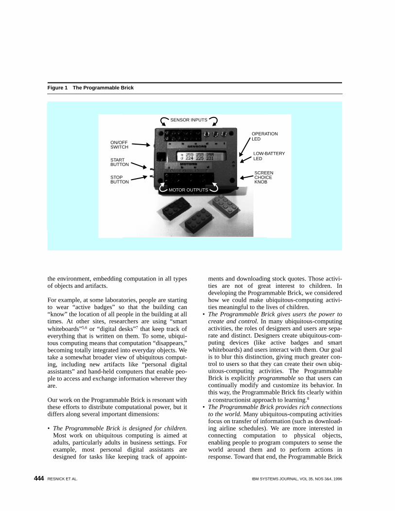
RESNICK ET AL. IBM SYSTEMS JOURNAL, VOL 35, NOS 3&4, 1996444
the environment, embedding computation in all typesof objects and artifacts.
For example, at some laboratories, people are startingto wear “active badges” so that the building can“know” the location of all people in the building at alltimes. At other sites, researchers are using “smartwhiteboards”5,6 or “digital desks”7 that keep track ofeverything that is written on them. To some, ubiqui-tous computing means that computation “disappears,”becoming totally integrated into everyday objects. Wetake a somewhat broader view of ubiquitous comput-ing, including new artifacts like “personal digitalassistants” and hand-held computers that enable peo-ple to access and exchange information wherever theyare.
Our work on the Programmable Brick is resonant withthese efforts to distribute computational power, but itdiffers along several important dimensions:
• The Programmable Brick is designed for children.Most work on ubiquitous computing is aimed atadults, particularly adults in business settings. Forexample, most personal digital assistants aredesigned for tasks like keeping track of appoint-
ments and downloading stock quotes. Those activi-ties are not of great interest to children. Indeveloping the Programmable Brick, we consideredhow we could make ubiquitous-computing activi-ties meaningful to the lives of children.
• The Programmable Brick gives users the power tocreate and control. In many ubiquitous-computingactivities, the roles of designers and users are sepa-rate and distinct. Designers create ubiquitous-com-puting devices (like active badges and smartwhiteboards) and users interact with them. Our goalis to blur this distinction, giving much greater con-trol to users so that they can create their own ubiq-uitous-computing activities. The ProgrammableBrick is explicitly programmable so that users cancontinually modify and customize its behavior. Inthis way, the Programmable Brick fits clearly withina constructionist approach to learning.8
• The Programmable Brick provides rich connectionsto the world. Many ubiquitous-computing activitiesfocus on transfer of information (such as download-ing airline schedules). We are more interested inconnecting computation to physical objects,enabling people to program computers to sense theworld around them and to perform actions inresponse. Toward that end, the Programmable Brick
Figure 1 The Programmable Brick
SENSOR INPUTS
ON/OFFSWITCH
STARTBUTTON
STOPBUTTON
MOTOR OUTPUTS
SCREENCHOICEKNOB
LOW-BATTERYLED
OPERATIONLED
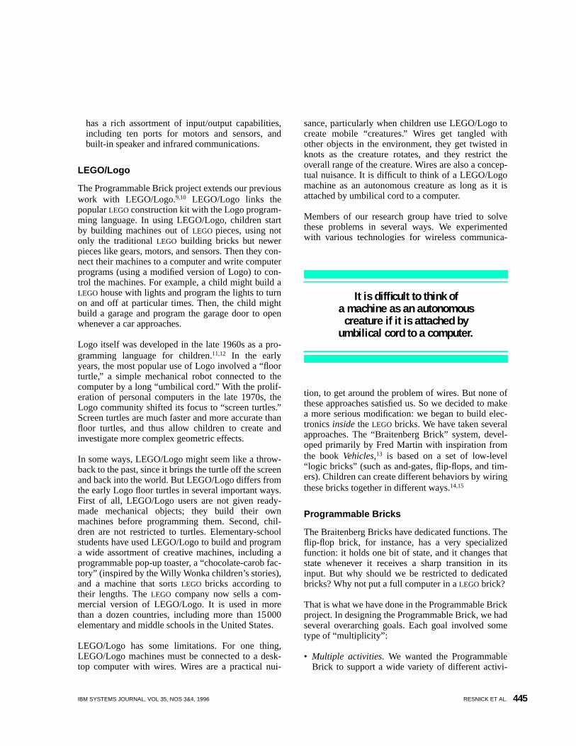
IBM SYSTEMS JOURNAL, VOL 35, NOS 3&4, 1996 RESNICK ET AL. 445
has a rich assortment of input/output capabilities,including ten ports for motors and sensors, andbuilt-in speaker and infrared communications.
LEGO/Logo
The Programmable Brick project extends our previouswork with LEGO/Logo.9,10 LEGO/Logo links thepopularLEGO construction kit with the Logo program-ming language. In using LEGO/Logo, children startby building machines out ofLEGO pieces, using notonly the traditionalLEGO building bricks but newerpieces like gears, motors, and sensors. Then they con-nect their machines to a computer and write computerprograms (using a modified version of Logo) to con-trol the machines. For example, a child might build aLEGO house with lights and program the lights to turnon and off at particular times. Then, the child mightbuild a garage and program the garage door to openwhenever a car approaches.
Logo itself was developed in the late 1960s as a pro-gramming language for children.11,12 In the earlyyears, the most popular use of Logo involved a “floorturtle,” a simple mechanical robot connected to thecomputer by a long “umbilical cord.” With the prolif-eration of personal computers in the late 1970s, theLogo community shifted its focus to “screen turtles.”Screen turtles are much faster and more accurate thanfloor turtles, and thus allow children to create andinvestigate more complex geometric effects.
In some ways, LEGO/Logo might seem like a throw-back to the past, since it brings the turtle off the screenand back into the world. But LEGO/Logo differs fromthe early Logo floor turtles in several important ways.First of all, LEGO/Logo users are not given ready-made mechanical objects; they build their ownmachines before programming them. Second, chil-dren are not restricted to turtles. Elementary-schoolstudents have used LEGO/Logo to build and programa wide assortment of creative machines, including aprogrammable pop-up toaster, a “chocolate-carob fac-tory” (inspired by the Willy Wonka children’s stories),and a machine that sortsLEGO bricks according totheir lengths. TheLEGO company now sells a com-mercial version of LEGO/Logo. It is used in morethan a dozen countries, including more than 15000elementary and middle schools in the United States.
LEGO/Logo has some limitations. For one thing,LEGO/Logo machines must be connected to a desk-top computer with wires. Wires are a practical nui-
sance, particularly when children use LEGO/Logo tocreate mobile “creatures.” Wires get tangled withother objects in the environment, they get twisted inknots as the creature rotates, and they restrict theoverall range of the creature. Wires are also a concep-tual nuisance. It is difficult to think of a LEGO/Logomachine as an autonomous creature as long as it isattached by umbilical cord to a computer.
Members of our research group have tried to solvethese problems in several ways. We experimentedwith various technologies for wireless communica-
tion, to get around the problem of wires. But none ofthese approaches satisfied us. So we decided to makea more serious modification: we began to build elec-tronics inside theLEGO bricks. We have taken severalapproaches. The “Braitenberg Brick” system, devel-oped primarily by Fred Martin with inspiration fromthe bookVehicles,13 is based on a set of low-level“logic bricks” (such as and-gates, flip-flops, and tim-ers). Children can create different behaviors by wiringthese bricks together in different ways.14,15
Programmable Bricks
The Braitenberg Bricks have dedicated functions. Theflip-flop brick, for instance, has a very specializedfunction: it holds one bit of state, and it changes thatstate whenever it receives a sharp transition in itsinput. But why should we be restricted to dedicatedbricks? Why not put a full computer in aLEGO brick?
That is what we have done in the Programmable Brickproject. In designing the Programmable Brick, we hadseveral overarching goals. Each goal involved sometype of “multiplicity”:
• Multiple activities. We wanted the ProgrammableBrick to support a wide variety of different activi-
It is difficult to think ofa machine as an autonomous
creature if it is attached byumbilical cord to a computer.
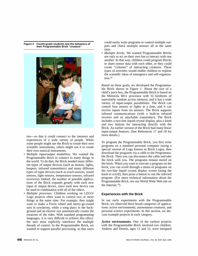
RESNICK ET AL. IBM SYSTEMS JOURNAL, VOL 35, NOS 3&4, 1996446
ties—so that it could connect to the interests andexperiences of a wide variety of people. Whilesome people might use the Brick to create their ownscientific instruments, others might use it to createtheir own musical instruments.
• Multiple input/output modalities. We wanted theProgrammable Brick to connect to many things inthe world. To do that, the Brick needed many differ-ent types of output devices (such as motors, lights,beepers, infrared transmitters) and many differenttypes of input devices (such as touch sensors, soundsensors, light sensors, temperature sensors, infraredreceivers). Indeed, the number of possible applica-tions of the Brick expands greatly with each newinput or output device, since each new device canbe used in combination with all of the others.
• Multiple processes. Children working on LEGO/Logo projects often want to control two or morethings at the same time. For example, they mightwant to make a Ferris wheel and merry-go-roundturn in synchrony, while a song plays in the back-ground and an electric eye automatically counts therotations of the rides. With standard programminglanguages, it is very difficult to achieve this effect:the user must explicitly interleave the multiplethreads of control. In the Programmable Brick, wewanted to support parallel processing, so that users
could easily write programs to control multiple out-puts and check multiple sensors all at the sametime.
• Multiple bricks. We wanted Programmable Bricksnot only to act on their own but to interact with oneanother. In that way, children could program Bricksto share sensor data with each other, or they couldcreate “colonies” of interacting creatures. Thesetypes of activities would enable children to explorethe scientific ideas of emergence and self-organiza-tion.16
Based on these goals, we developed the Programma-ble Brick shown in Figure 1. About the size of achild’s juice box, the Programmable Brick is based onthe Motorola 6811 processor with 32 kilobytes ofnonvolatile random access memory, and it has a widevariety of input-output possibilities. The Brick cancontrol four motors or lights at a time, and it canreceive inputs from six sensors. The Brick supportsinfrared communications (with a built-in infraredreceiver and an attachable transmitter). The Brickincludes a two-line liquid-crystal display, plus a knoband two buttons for interacting directly with theBrick. An earlier version of the Brick had many fewerinput-output features. (See References 17 and 18 formore details.)
To program the Programmable Brick, you first writeprograms on a standard personal computer (using aspecial version of Logo known as Brick Logo), thendownload the programs via a cable to the Programma-ble Brick. Then you can disconnect the cable and takethe brick with you. The programs remain stored onthe brick. When you want to execute a program on thebrick, you can scroll through a menu of programs onthe two-line liquid crystal display screen (using theknob to scroll), then press a button to run the selectedprogram. (For more technical information about theProgrammable Brick, see our World Wide Web site onthe Internet.19)
Experiences with the Brick
In our early experiments with the ProgrammableBrick, we observed three broad categories of applica-tions: active environments, autonomous creatures, andpersonal science experiments. In this section, we dis-cuss example projects in each category.
Active environments. One of the earliest projectswith the Programmable Brick involved two children.Andrew and Dennis, ages 11 and 12, were intrigued
Figure 2 Fourth-grade students test the behaviors oftheir Programmable Brick “creature”
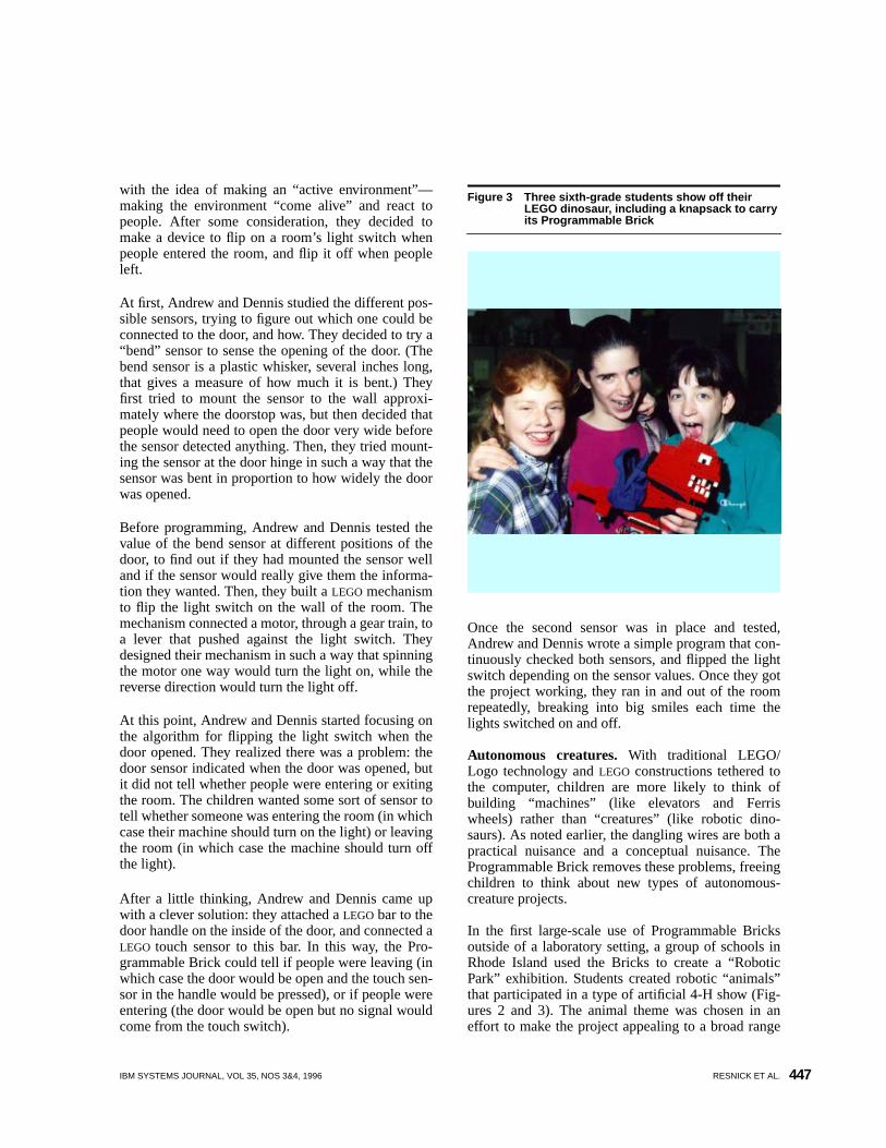
IBM SYSTEMS JOURNAL, VOL 35, NOS 3&4, 1996 RESNICK ET AL. 447
with the idea of making an “active environment”—making the environment “come alive” and react topeople. After some consideration, they decided tomake a device to flip on a room’s light switch whenpeople entered the room, and flip it off when peopleleft.
At first, Andrew and Dennis studied the different pos-sible sensors, trying to figure out which one could beconnected to the door, and how. They decided to try a“bend” sensor to sense the opening of the door. (Thebend sensor is a plastic whisker, several inches long,that gives a measure of how much it is bent.) Theyfirst tried to mount the sensor to the wall approxi-mately where the doorstop was, but then decided thatpeople would need to open the door very wide beforethe sensor detected anything. Then, they tried mount-ing the sensor at the door hinge in such a way that thesensor was bent in proportion to how widely the doorwas opened.
Before programming, Andrew and Dennis tested thevalue of the bend sensor at different positions of thedoor, to find out if they had mounted the sensor welland if the sensor would really give them the informa-tion they wanted. Then, they built aLEGO mechanismto flip the light switch on the wall of the room. Themechanism connected a motor, through a gear train, toa lever that pushed against the light switch. Theydesigned their mechanism in such a way that spinningthe motor one way would turn the light on, while thereverse direction would turn the light off.
At this point, Andrew and Dennis started focusing onthe algorithm for flipping the light switch when thedoor opened. They realized there was a problem: thedoor sensor indicated when the door was opened, butit did not tell whether people were entering or exitingthe room. The children wanted some sort of sensor totell whether someone was entering the room (in whichcase their machine should turn on the light) or leavingthe room (in which case the machine should turn offthe light).
After a little thinking, Andrew and Dennis came upwith a clever solution: they attached aLEGO bar to thedoor handle on the inside of the door, and connected aLEGO touch sensor to this bar. In this way, the Pro-grammable Brick could tell if people were leaving (inwhich case the door would be open and the touch sen-sor in the handle would be pressed), or if people wereentering (the door would be open but no signal wouldcome from the touch switch).
Once the second sensor was in place and tested,Andrew and Dennis wrote a simple program that con-tinuously checked both sensors, and flipped the lightswitch depending on the sensor values. Once they gotthe project working, they ran in and out of the roomrepeatedly, breaking into big smiles each time thelights switched on and off.
Autonomous creatures. With traditional LEGO/Logo technology andLEGO constructions tethered tothe computer, children are more likely to think ofbuilding “machines” (like elevators and Ferriswheels) rather than “creatures” (like robotic dino-saurs). As noted earlier, the dangling wires are both apractical nuisance and a conceptual nuisance. TheProgrammable Brick removes these problems, freeingchildren to think about new types of autonomous-creature projects.
In the first large-scale use of Programmable Bricksoutside of a laboratory setting, a group of schools inRhode Island used the Bricks to create a “RoboticPark” exhibition. Students created robotic “animals”that participated in a type of artificial 4-H show (Fig-ures 2 and 3). The animal theme was chosen in aneffort to make the project appealing to a broad range
Figure 3 Three sixth-grade students show off theirLEGO dinosaur, including a knapsack to carryits Programmable Brick
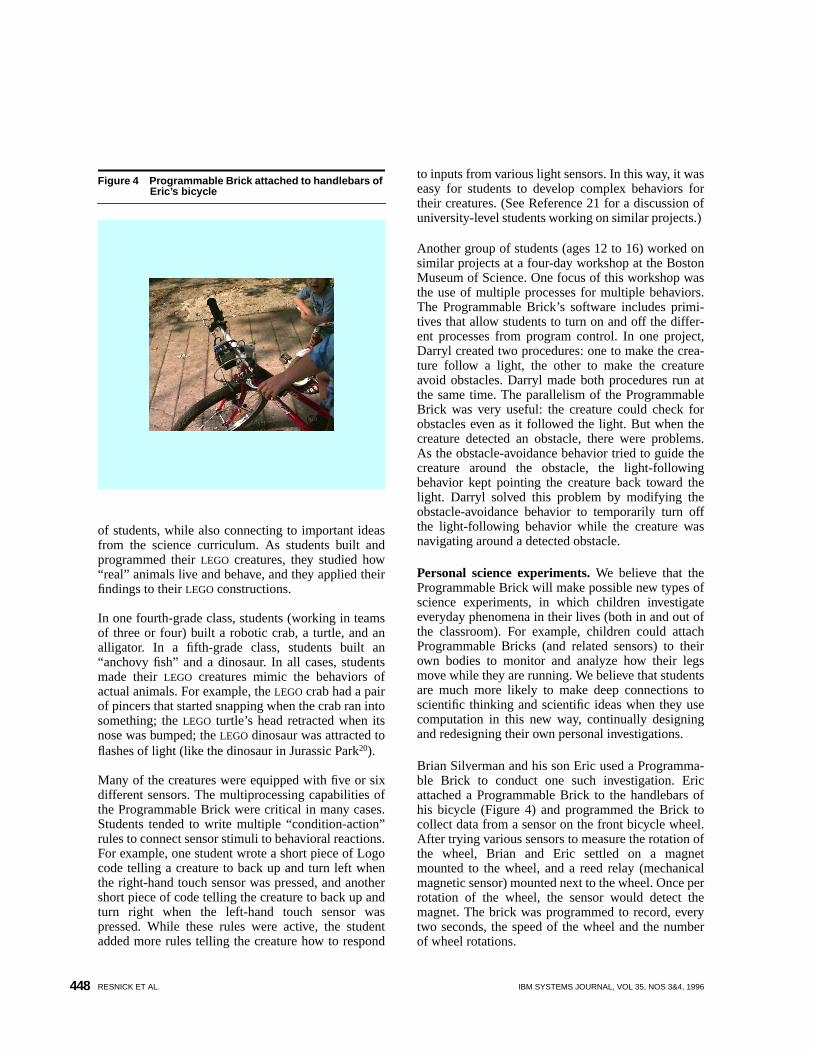
RESNICK ET AL. IBM SYSTEMS JOURNAL, VOL 35, NOS 3&4, 1996448
of students, while also connecting to important ideasfrom the science curriculum. As students built andprogrammed theirLEGO creatures, they studied how“real” animals live and behave, and they applied theirfindings to theirLEGO constructions.
In one fourth-grade class, students (working in teamsof three or four) built a robotic crab, a turtle, and analligator. In a fifth-grade class, students built an“anchovy fish” and a dinosaur. In all cases, studentsmade theirLEGO creatures mimic the behaviors ofactual animals. For example, theLEGO crab had a pairof pincers that started snapping when the crab ran intosomething; theLEGO turtle’s head retracted when itsnose was bumped; theLEGO dinosaur was attracted toflashes of light (like the dinosaur in Jurassic Park20).
Many of the creatures were equipped with five or sixdifferent sensors. The multiprocessing capabilities ofthe Programmable Brick were critical in many cases.Students tended to write multiple “condition-action”rules to connect sensor stimuli to behavioral reactions.For example, one student wrote a short piece of Logocode telling a creature to back up and turn left whenthe right-hand touch sensor was pressed, and anothershort piece of code telling the creature to back up andturn right when the left-hand touch sensor waspressed. While these rules were active, the studentadded more rules telling the creature how to respond
to inputs from various light sensors. In this way, it waseasy for students to develop complex behaviors fortheir creatures. (See Reference 21 for a discussion ofuniversity-level students working on similar projects.)
Another group of students (ages 12 to 16) worked onsimilar projects at a four-day workshop at the BostonMuseum of Science. One focus of this workshop wasthe use of multiple processes for multiple behaviors.The Programmable Brick’s software includes primi-tives that allow students to turn on and off the differ-ent processes from program control. In one project,Darryl created two procedures: one to make the crea-ture follow a light, the other to make the creatureavoid obstacles. Darryl made both procedures run atthe same time. The parallelism of the ProgrammableBrick was very useful: the creature could check forobstacles even as it followed the light. But when thecreature detected an obstacle, there were problems.As the obstacle-avoidance behavior tried to guide thecreature around the obstacle, the light-followingbehavior kept pointing the creature back toward thelight. Darryl solved this problem by modifying theobstacle-avoidance behavior to temporarily turn offthe light-following behavior while the creature wasnavigating around a detected obstacle.
Personal science experiments. We believe that theProgrammable Brick will make possible new types ofscience experiments, in which children investigateeveryday phenomena in their lives (both in and out ofthe classroom). For example, children could attachProgrammable Bricks (and related sensors) to theirown bodies to monitor and analyze how their legsmove while they are running. We believe that studentsare much more likely to make deep connections toscientific thinking and scientific ideas when they usecomputation in this new way, continually designingand redesigning their own personal investigations.
Brian Silverman and his son Eric used a Programma-ble Brick to conduct one such investigation. Ericattached a Programmable Brick to the handlebars ofhis bicycle (Figure 4) and programmed the Brick tocollect data from a sensor on the front bicycle wheel.After trying various sensors to measure the rotation ofthe wheel, Brian and Eric settled on a magnetmounted to the wheel, and a reed relay (mechanicalmagnetic sensor) mounted next to the wheel. Once perrotation of the wheel, the sensor would detect themagnet. The brick was programmed to record, everytwo seconds, the speed of the wheel and the numberof wheel rotations.
Figure 4 Programmable Brick attached to handlebars ofEric’s bicycle
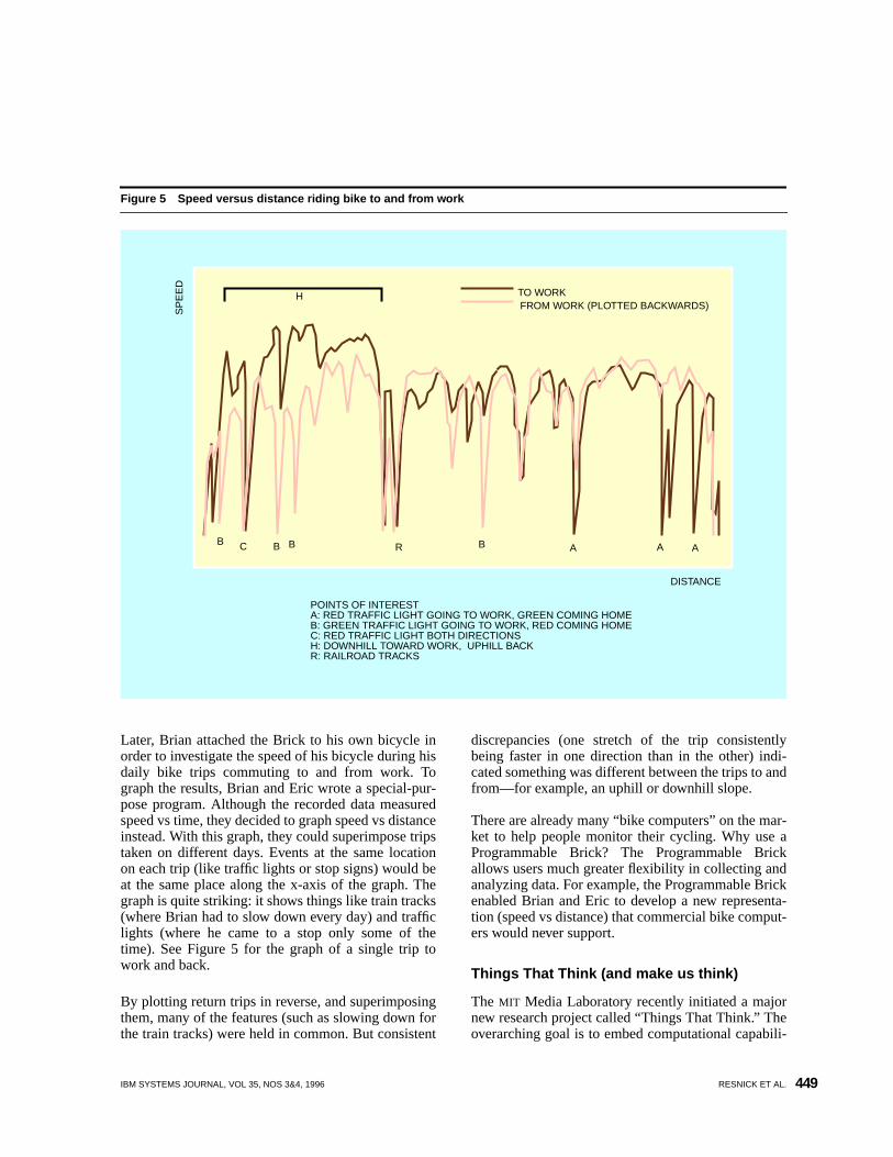
IBM SYSTEMS JOURNAL, VOL 35, NOS 3&4, 1996 RESNICK ET AL. 449
Later, Brian attached the Brick to his own bicycle inorder to investigate the speed of his bicycle during hisdaily bike trips commuting to and from work. Tograph the results, Brian and Eric wrote a special-pur-pose program. Although the recorded data measuredspeed vs time, they decided to graph speed vs distanceinstead. With this graph, they could superimpose tripstaken on different days. Events at the same locationon each trip (like traffic lights or stop signs) would beat the same place along the x-axis of the graph. Thegraph is quite striking: it shows things like train tracks(where Brian had to slow down every day) and trafficlights (where he came to a stop only some of thetime). See Figure 5 for the graph of a single trip towork and back.
By plotting return trips in reverse, and superimposingthem, many of the features (such as slowing down forthe train tracks) were held in common. But consistent
discrepancies (one stretch of the trip consistentlybeing faster in one direction than in the other) indi-cated something was different between the trips to andfrom—for example, an uphill or downhill slope.
There are already many “bike computers” on the mar-ket to help people monitor their cycling. Why use aProgrammable Brick? The Programmable Brickallows users much greater flexibility in collecting andanalyzing data. For example, the Programmable Brickenabled Brian and Eric to develop a new representa-tion (speed vs distance) that commercial bike comput-ers would never support.
Things That Think (and make us think)
The MIT Media Laboratory recently initiated a majornew research project called “Things That Think.” Theoverarching goal is to embed computational capabili-
Figure 5 Speed versus distance riding bike to and from work
A A ABBBB RC
H TO WORKFROM WORK (PLOTTED BACKWARDS)
DISTANCE
SP
EE
D
POINTS OF INTERESTA: RED TRAFFIC LIGHT GOING TO WORK, GREEN COMING HOMEB: GREEN TRAFFIC LIGHT GOING TO WORK, RED COMING HOMEC: RED TRAFFIC LIGHT BOTH DIRECTIONSH: DOWNHILL TOWARD WORK, UPHILL BACKR: RAILROAD TRACKS
RESNICK ET AL. IBM SYSTEMS JOURNAL, VOL 35, NOS 3&4, 1996450
ties in everyday objects like furniture, shoes, and toys.The Programmable Brick fits within this new initia-tive—but with an important twist. In our work, we areinterested in things that think, not because they mightaccomplish particular tasks more cheaply or easily orintelligently, but because they might enable people to
think about things in new ways. That is, things thatthink are most interesting to us when they also act as“things to think with.” We believe that ProgrammableBricks act in just that way, enabling children to per-form new types of explorations and experiments andto engage in new types of thinking.
The Programmable Brick project is just beginning; wehave many ideas for future extensions. We are cur-rently developing a new set of bricks, known as Crick-ets, that are much smaller and lighter than the originalProgrammable Bricks. Each Cricket is not much big-ger than the 9-volt battery that powers it. A Cricketcan control two motors and receive information fromtwo sensors, and it comes with built-in two-way infra-red communications capabilities for “talking” withother Crickets and other electronic devices. The smallsize of the Crickets, along with their enhanced com-munication capabilities, opens up new possibilities forapplications. People might wear the Crickets toexchange information with one another, as in theThinking Tags project (described elsewhere in thisissue22). Or children might use the Crickets to experi-ment with decentralized and self-organizing phenom-ena, creating a whole “colony” of ant-like mobilerobots that interact with one another.
There are still many obstacles to the widespread useof Programmable Bricks and Crickets—especially inschool settings. The major obstacles are not techno-logical, but in the structure and organization ofschools themselves. Most interesting ProgrammableBrick projects require extended blocks of time; theycannot be squeezed into standard 50-minute class ses-sions or standard two-week curriculum units. More-over, Programmable Brick projects typically cut
across disciplinary boundaries, and they often engagestudents in thinking about ideas (such as feedbackloops) that are not traditionally included in precollegecurricula. As a result, educators are not quite surewhere to “fit” Programmable Brick activities. For theProgrammable Brick to become successful in schoolsettings, we need to work with educators to find waysaround these constraints. Indeed, one of the mostimportant effects of new technologies like the Pro-grammable Brick is that they can provoke us torethink some of our basic assumptions about educa-tion.
Acknowledgments
Seymour Papert, Steve Ocko, and Allan Toft haveprovided encouragement, inspiration, and ideas forthe Programmable Brick project. Andrew Blumberg,Yuying Chen, Fei Hai Chua, Dennis Evangelista,Chris Gatta, Hanna Jang, Owen Johnson, Mark Neri,Brian Robertson, Victor Tsou, and Elaine Yang allcontributed to the development effort. TheLEGOGroup and the National Science Foundation (Grants9153719-MDR, 8751190-MDR, and RED-9358519)have provided financial support. Portions of this paperpreviously appeared in Reference 23.
For more information on the Programmable Brick, seeour World Wide Web site on the Internet.19
Appendix: Twenty things to do with aProgrammable Brick
More than 20 years ago, as researchers and educatorswere just beginning to explore the possibilities ofcomputers in education, Seymour Papert and CynthiaSolomon wrote a memo called “Twenty Things to Dowith a Computer.”24The memo described a wonderfulcollection of activities, pushing computers in direc-tions that few other people had imagined. Some of theactivities on their list eventually became common-place; others are still visionary today. A few yearslater, Danny Hillis (then an undergraduate atMIT)wrote a memo entitled “Ten Things to Do with a Bet-ter Computer,”25 describing a new set of activities thatwould be possible if computers could execute instruc-tions in parallel. Hillis later realized some of theseideas in his massively parallel Connection Machinecomputer.26
In the same spirit, we have compiled a new list enti-tled “Twenty Things to Do with a ProgrammableBrick.”10
“Things that think”are more interestingwhen they also act as“things to think with.”
IBM SYSTEMS JOURNAL, VOL 35, NOS 3&4, 1996 RESNICK ET AL. 451
1. Create a “haunted house.” Attach a Programma-ble Brick to the door to make creaking soundswhenever the door is opened. Program anotherBrick to drop spiders on people when they walkthrough the door. Build aLEGO platform for apumpkin, and program a Brick to drive the pump-kin around the room.
2. Connect sensors to various parts of your body.Then program a Programmable Brick to monitoryour heartbeat and breathing as you walk and run.Or program the Brick to play different soundswhen you move different parts of your body.
3. Take a Programmable Brick with you to measurethe pH level of the water in local streams, or thenoise levels at a local construction site.
4. Create aLEGO musical instrument. The instru-ment might have buttons like a flute, or a slidingpart like a trombone, or a completely new inter-face that you invent. Start by writing a simpleprogram so that the Programmable Brick playsdifferent notes (or melodies) when you move dif-ferent parts of the instrument. Then enhance theprogram so that the Brick improvises on yournotes. Or program the Brick to play “rounds” (byplaying a second copy of your notes with adelay).
5. Put a Programmable Brick and light sensor on thedoor to keep track of the number of people thatenter the room. Then program the Brick to greetpeople as they enter the room (with music or dig-itized speech).
6. Set up a weather station on the roof of the build-ing.
7. Use a Programmable Brick to find out if the lightreally does go off when you shut the refrigeratordoor.
8. Attach a Programmable Brick to an ashtray, andprogram it to play a coughing sound wheneveranyone uses the ashtray.
9. Build a remote-controlledLEGO car. Use a stan-dard television remote control to communicate(via infrared transmission) with a ProgrammableBrick in the car.
10. Create an “intelligent room” that automaticallyturns on the lights when someone walks in theroom. (Here’s one approach. Build aLEGOmachine that turns on the light switch, and con-nect it to a Programmable Brick. Use anotherProgrammable Brick to detect when anyoneenters the room. Use infrared transmission tocommunicate between the two Bricks.)
11. Use a Programmable Brick to control a video-camera (via infrared transmission). Program the
Brick to make a time-lapse video of a plant grow-ing (taking a few frames every hour or day).
12. Use a Programmable Brick to program yourVCR.13. Send secret messages across the room to some-
one else who also has a Programmable Brick.14. Put a Brick on your dog’s collar and collect data
about your dog’s behavior. How much time doesyour dog spend running around? Discuss whetherexperimenting on your dog is ethical.
15. Use a Brick to record your dog barking. Then putthe Brick in a remote-controlledLEGO car. Playthe barking sound when theLEGO car gets near acat. How does the cat react?
16. Build aLEGO creature that you can interact with.Program the creature to act in different wayswhen you clap once, or clap twice, or shine a lightin its “eyes.”
17. Build aLEGO creature that explores its environ-ment. Program the creature to find the part of theroom with the most light or the highest tempera-ture. Next, put a plant on yourLEGO creature, sothat the plant will always move to the part of theroom with the most light (or the highest tempera-ture). Use other sensors to monitor the growth ofthe plant.
18. Build aLEGO machine that can water your plants,then program a Brick to make the machine waterthe plants every few days.
19. Create a game where each player carries a Pro-grammable Brick. Program the Bricks so thatthey give instructions to the players, and sendmessages from one player to another.
20. Think up 20 more things to do with a Program-mable Brick.
**Trademark or registered trademark of LEGO Systems, Incorpo-rated.
Cited references
1. H. Abelson and A. diSessa,Turtle Geometry: The Computer asa Medium for Exploring Mathematics, MIT Press, Cambridge,MA (1980).
2. W. Wright,SimCity, Maxis, Orinda, CA (1990).3. P. Wellner, W. Mackay, and R. Gold, “Computer Augmented
Environments: Back to the Real World,”Communications ofthe ACM36, No. 7, 24–26 (July 1993).
4. M. Weiser, “The Computer for the 21st Century,”ScientificAmerican265, No. 3, 94–104 (September, 1991).
5. S. Elrod, R. Bruce, R. Gold, D. Goldberg, F. Halasz, W. Jans-sen, D. Lee, K. McCall, E. Pedersen, K. Pier, J. Tang, andB. Welch, “Liveboard: A Large Interactive Display SupportingGroup Meetings, Presentations, and Remote Collaborations,”Proceedings, ACM Conference on Human Factors in Comput-ing Systems, ACM Press, New York (1992), pp. 599–607.
6. M. Weiser, “Some Computer Science Issues in Ubiquitous
RESNICK ET AL. IBM SYSTEMS JOURNAL, VOL 35, NOS 3&4, 1996452
Computing,” Communications of the ACM,36 No. 7, 25–26(July, 1993).
7. P. Wellner, “Interacting with Paper on the Digital Desk,”Com-munications of the ACM36, No. 7, 87–96 (July, 1993).
8. S. Papert, “Situating Constructionism,” I. Harel and S. Papert,Editors, Constructionism, Ablex Publishing, Norwood, NJ(1991).
9. M. Resnick, S. Ocko, and S. Papert, “LEGO, Logo, andDesign,” Children’s Environments Quarterly5, No. 4, 14–18(1988).
10. M. Resnick, “Behavior Construction Kits,”Communications ofthe ACM36, No. 7, 64–71 (July 1993).
11. S. Papert,Mindstorms: Children, Computers, and PowerfulIdeas, Basic Books, New York (1980).
12. B. Harvey,Computer Science Logo Style, MIT Press, Cam-bridge, MA (1985).
13. V. Braitenberg,Vehicles, MIT Press, Cambridge, MA (1984).14. N. Granott, “Puzzled Minds and Weird Creatures: Spontaneous
Inquiry and Phases in Knowledge Construction,” I. Harel andS. Papert, Editors,Constructionism, Ablex Publishing, Nor-wood, NJ (1991).
15. D. Hogg, F. Martin, and M. Resnick, “Braitenberg Creatures,”Epistemology and Learning Memo 13, MIT Media Laboratory,Cambridge, MA (1991).
16. M. Resnick,Turtles, Termites, and Traffic Jams, MIT Press,Cambridge, MA (1994).
17. F. Martin,Children, Cybernetics, and Programmable Turtles,master’s degree thesis, MIT Media Laboratory, Cambridge,MA (1988).
18. M. Bourgoin, “Children Using LEGO Robots to ExploreDynamics,” I. Harel, Editor,Constructionist Learning, MITMedia Laboratory, Cambridge, MA (1990).
19. The World Wide Web site for the Programmable Brick is athttp://el.www.media.mit.edu/groups/el/projects/programmable-brick/.
20. M. Crichton, Jurassic Park, Alfred A. Knopf, New York(1990). The 1993 movie based on the book was directed bySteven Spielberg.
21. F. Martin, Circuits to Control: Learning Engineering byDesigning LEGO Robots, Ph.D. dissertation, MIT Media Labo-ratory, Cambridge, MA (1994).
22. R. Borovoy, M. McDonald, F. Martin, and M. Resnick, “ThingsThat Blink: Computationally Augmented Name Tags,”IBMSystems Journal35, Nos. 3&4, 488–495 (1996, this issue).
23. R. Sargent, M. Resnick, F. Martin, and B. Silverman, “Buildingand Learning with Programmable Bricks,” Y. Kafai andM. Resnick, Editors,Constructionism in Practice, LawrenceErlbaum, Mahwah, NJ (1996).
24. S. Papert and C. Solomon, “Twenty Things to Do with a Com-puter,” Artificial Intelligence Memo 248, MIT Artificial Intelli-gence Laboratory, Cambridge, MA (1971).
25. W. D. Hillis, “Ten Things to Do with a Better Computer,”unpublished memo available from MIT Artificial IntelligenceLaboratory, Cambridge, MA (1975).
26. W. D. Hillis,The Connection Machine, MIT Press, Cambridge,MA (1985).
Accepted for publication April 4, 1996.
Mitchel Resnick MIT Media Laboratory, 20 Ames Street, Cam-bridge, Massachusetts 02139-4307 (electronic mail: [email protected]). Dr. Resnick, an associate professor at the MITMedia Laboratory, studies the role of new technological tools inlearning and education. He has helped develop a variety of “compu-tational construction kits” (including LEGO/Logo and StarLogo),
and he cofounded the Computer Clubhouse, an afterschool learningcenter for youth from under-served communities. He earned a B.A.in physics at Princeton University, and M.S. and Ph.D. degrees incomputer science at MIT. He won a National Science FoundationYoung Investigator Award in 1993, and he is author of the bookTurtles, Termites, and Traffic Jams, published by MIT Press. Dr.Resnick is on the Board of Overseers and is chair of the educationcommittee at The Computer Museum.
Fred Martin MIT Media Laboratory, 20 Ames Street, Cambridge,Massachusetts 02139-4307 (electronic mail: [email protected]). Dr. Martin earned a B.S. degree in computer science in 1986,an M.S. in mechanical engineering in 1988, and a Ph.D. in mediaarts and sciences in 1994, all from the Massachusetts Institute ofTechnology. His doctoral dissertation explored learning in an inten-sive, design-rich robot-building class he codeveloped for MITundergraduates. Dr. Martin’s research interests include: the role ofexperiential knowledge in learning formal scientific and engineer-ing methods; design-rich environments for learning; and robots as amedium for exploring engineering practice. He is presently aresearch scientist with the Epistemology and Learning Group at theMIT Media Laboratory.
Randy Sargent Newton Research Labs, 14813 NE 13th Street,Bellevue, Washington 98007 (electronic mail: [email protected]). Mr. Sargent holds a bachelor’s degree in computerscience and a master’s degree in media arts and sciences, both fromMIT. He was a founding organizer of the MIT robot design compe-tition, and he was centrally involved in the development of the Pro-grammable Brick. He is a cofounder of Newton Research Labs, asoftware company developing products for robotics hobbyists andresearchers.
Brian Silverman Logo Computer Systems Inc., P.O. Box 162,Highgate Springs, Vermont 05460 (electronic mail: [email protected]).Mr. Silverman is Director of Research at Logo Computer SystemsInc. (LCSI) and a visiting scientist at the MIT Media Lab. He wasone of the founders of LCSI, the world’s leading developer of Logosoftware. He has directed the development of more than a dozencommercial educational software products (including LogoWriter,MicroWorlds, and the Phantom Fishtank), many of which have wonmajor awards from industry groups and publications. At MIT, hehas been centrally involved in the development of StarLogo, Pro-grammable Bricks, and Crickets.
Reprint Order No. G321-5616.
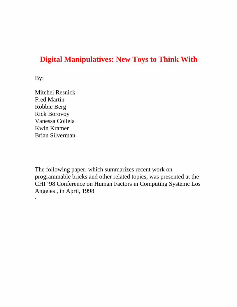
Digital Manipulatives: New Toys to Think With
By:
Mitchel ResnickFred MartinRobbie BergRick BorovoyVanessa CollelaKwin KramerBrian Silverman
The following paper, which summarizes recent work onprogrammable bricks and other related topics, was presented at theCHI ‘98 Conference on Human Factors in Computing Systemc LosAngeles , in April, 1998.
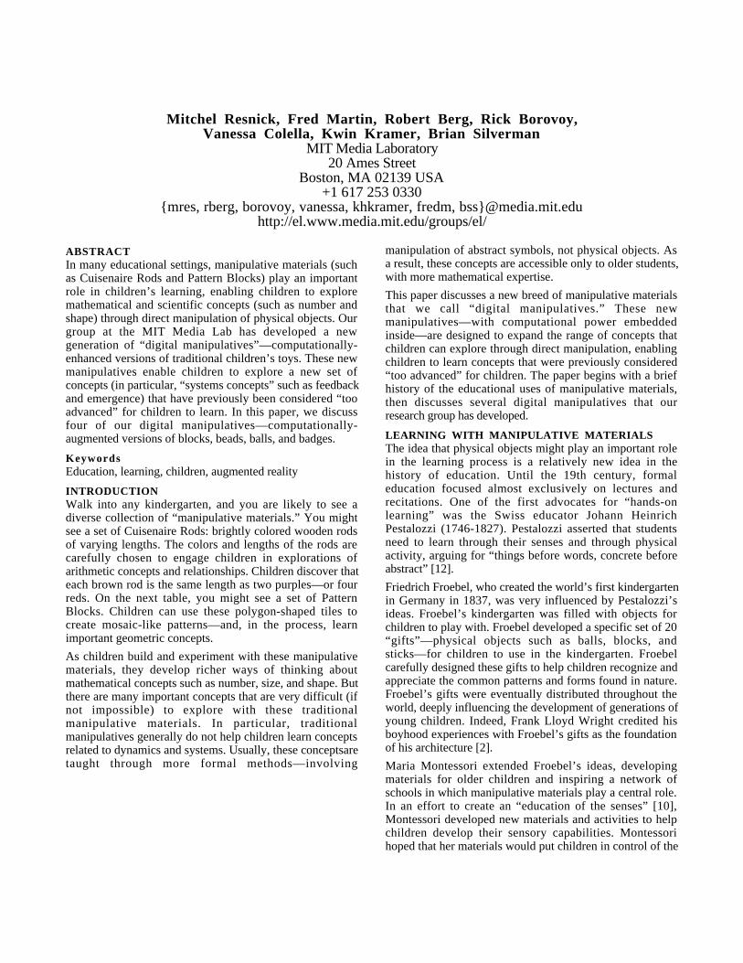
Mitchel Resnick, Fred Martin, Robert Berg, Rick Borovoy,Vanessa Colella, Kwin Kramer, Brian Silverman
MIT Media Laboratory20 Ames Street
Boston, MA 02139 USA+1 617 253 0330
{mres, rberg, borovoy, vanessa, khkramer, fredm, bss}@media.mit.eduhttp://el.www.media.mit.edu/groups/el/
ABSTRACTIn many educational settings, manipulative materials (suchas Cuisenaire Rods and Pattern Blocks) play an importantrole in children’s learning, enabling children to exploremathematical and scientific concepts (such as number andshape) through direct manipulation of physical objects. Ourgroup at the MIT Media Lab has developed a newgeneration of “digital manipulatives”—computationally-enhanced versions of traditional children’s toys. These newmanipulatives enable children to explore a new set ofconcepts (in particular, “systems concepts” such as feedbackand emergence) that have previously been considered “tooadvanced” for children to learn. In this paper, we discussfour of our digital manipulatives—computationally-augmented versions of blocks, beads, balls, and badges.
KeywordsEducation, learning, children, augmented reality
INTRODUCTIONWalk into any kindergarten, and you are likely to see adiverse collection of “manipulative materials.” You mightsee a set of Cuisenaire Rods: brightly colored wooden rodsof varying lengths. The colors and lengths of the rods arecarefully chosen to engage children in explorations ofarithmetic concepts and relationships. Children discover thateach brown rod is the same length as two purples—or fourreds. On the next table, you might see a set of PatternBlocks. Children can use these polygon-shaped tiles tocreate mosaic-like patterns—and, in the process, learnimportant geometric concepts.
As children build and experiment with these manipulativematerials, they develop richer ways of thinking aboutmathematical concepts such as number, size, and shape. Butthere are many important concepts that are very difficult (ifnot impossible) to explore with these traditionalmanipulative materials. In particular, traditionalmanipulatives generally do not help children learn conceptsrelated to dynamics and systems. Usually, these conceptsaretaught through more formal methods—involving
manipulation of abstract symbols, not physical objects. Asa result, these concepts are accessible only to older students,with more mathematical expertise.
This paper discusses a new breed of manipulative materialsthat we call “digital manipulatives.” These newmanipulatives—with computational power embeddedinside—are designed to expand the range of concepts thatchildren can explore through direct manipulation, enablingchildren to learn concepts that were previously considered“too advanced” for children. The paper begins with a briefhistory of the educational uses of manipulative materials,then discusses several digital manipulatives that ourresearch group has developed.
LEARNING WITH MANIPULATIVE MATERIALSThe idea that physical objects might play an important rolein the learning process is a relatively new idea in thehistory of education. Until the 19th century, formaleducation focused almost exclusively on lectures andrecitations. One of the first advocates for “hands-onlearning” was the Swiss educator Johann HeinrichPestalozzi (1746-1827). Pestalozzi asserted that studentsneed to learn through their senses and through physicalactivity, arguing for “things before words, concrete beforeabstract” [12].
Friedrich Froebel, who created the world’s first kindergartenin Germany in 1837, was very influenced by Pestalozzi’sideas. Froebel’s kindergarten was filled with objects forchildren to play with. Froebel developed a specific set of 20“gifts”—physical objects such as balls, blocks, andsticks—for children to use in the kindergarten. Froebelcarefully designed these gifts to help children recognize andappreciate the common patterns and forms found in nature.Froebel’s gifts were eventually distributed throughout theworld, deeply influencing the development of generations ofyoung children. Indeed, Frank Lloyd Wright credited hisboyhood experiences with Froebel’s gifts as the foundationof his architecture [2].
Maria Montessori extended Froebel’s ideas, developingmaterials for older children and inspiring a network ofschools in which manipulative materials play a central role.In an effort to create an “education of the senses” [10],Montessori developed new materials and activities to helpchildren develop their sensory capabilities. Montessorihoped that her materials would put children in control of the
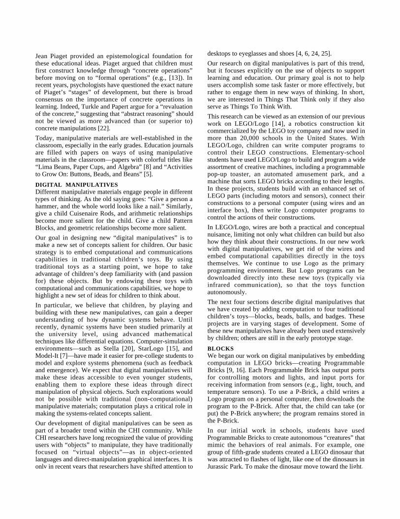
g p
Jean Piaget provided an epistemological foundation forthese educational ideas. Piaget argued that children mustfirst construct knowledge through “concrete operations”before moving on to “formal operations” (e.g., [13]). Inrecent years, psychologists have questioned the exact natureof Piaget’s “stages” of development, but there is broadconsensus on the importance of concrete operations inlearning. Indeed, Turkle and Papert argue for a “revaluationof the concrete,” suggesting that “abstract reasoning” shouldnot be viewed as more advanced than (or superior to)concrete manipulations [22].
Today, manipulative materials are well-established in theclassroom, especially in the early grades. Education journalsare filled with papers on ways of using manipulativematerials in the classroom—papers with colorful titles like“Lima Beans, Paper Cups, and Algebra” [8] and “Activitiesto Grow On: Buttons, Beads, and Beans” [5].
DIGITAL MANIPULATIVESDifferent manipulative materials engage people in differenttypes of thinking. As the old saying goes: “Give a person ahammer, and the whole world looks like a nail.” Similarly,give a child Cuisenaire Rods, and arithmetic relationshipsbecome more salient for the child. Give a child PatternBlocks, and geometric relationships become more salient.
Our goal in designing new “digital manipulatives” is tomake a new set of concepts salient for children. Our basicstrategy is to embed computational and communicationscapabilities in traditional children’s toys. By usingtraditional toys as a starting point, we hope to takeadvantage of children’s deep familiarity with (and passionfor) these objects. But by endowing these toys withcomputational and communications capabilities, we hope tohighlight a new set of ideas for children to think about.
In particular, we believe that children, by playing andbuilding with these new manipulatives, can gain a deeperunderstanding of how dynamic systems behave. Untilrecently, dynamic systems have been studied primarily atthe university level, using advanced mathematicaltechniques like differential equations. Computer-simulationenvironments—such as Stella [20], StarLogo [15], andModel-It [7]—have made it easier for pre-college students tomodel and explore systems phenomena (such as feedbackand emergence). We expect that digital manipulatives willmake these ideas accessible to even younger students,enabling them to explore these ideas through directmanipulation of physical objects. Such explorations wouldnot be possible with traditional (non-computational)manipulative materials; computation plays a critical role inmaking the systems-related concepts salient.
Our development of digital manipulatives can be seen aspart of a broader trend within the CHI community. WhileCHI researchers have long recognized the value of providingusers with “objects” to manipulate, they have traditionallyfocused on “virtual objects”—as in object-orientedlanguages and direct-manipulation graphical interfaces. It isonly in recent years that researchers have shifted attention to
p y y j g g pdesktops to eyeglasses and shoes [4, 6, 24, 25].
Our research on digital manipulatives is part of this trend,but it focuses explicitly on the use of objects to supportlearning and education. Our primary goal is not to helpusers accomplish some task faster or more effectively, butrather to engage them in new ways of thinking. In short,we are interested in Things That Think only if they alsoserve as Things To Think With.
This research can be viewed as an extension of our previouswork on LEGO/Logo [14], a robotics construction kitcommercialized by the LEGO toy company and now used inmore than 20,000 schools in the United States. WithLEGO/Logo, children can write computer programs tocontrol their LEGO constructions. Elementary-schoolstudents have used LEGO/Logo to build and program a wideassortment of creative machines, including a programmablepop-up toaster, an automated amusement park, and amachine that sorts LEGO bricks according to their lengths.In these projects, students build with an enhanced set ofLEGO parts (including motors and sensors), connect theirconstructions to a personal computer (using wires and aninterface box), then write Logo computer programs tocontrol the actions of their constructions.
In LEGO/Logo, wires are both a practical and conceptualnuisance, limiting not only what children can build but alsohow they think about their constructions. In our new workwith digital manipulatives, we get rid of the wires andembed computational capabilities directly in the toysthemselves. We continue to use Logo as the primaryprogramming environment. But Logo programs can bedownloaded directly into these new toys (typically viainfrared communication), so that the toys functionautonomously.
The next four sections describe digital manipulatives thatwe have created by adding computation to four traditionalchildren’s toys—blocks, beads, balls, and badges. Theseprojects are in varying stages of development. Some ofthese new manipulatives have already been used extensivelyby children; others are still in the early prototype stage.
BLOCKSWe began our work on digital manipulatives by embeddingcomputation in LEGO bricks—creating ProgrammableBricks [9, 16]. Each Programmable Brick has output portsfor controlling motors and lights, and input ports forreceiving information from sensors (e.g., light, touch, andtemperature sensors). To use a P-Brick, a child writes aLogo program on a personal computer, then downloads theprogram to the P-Brick. After that, the child can take (orput) the P-Brick anywhere; the program remains stored inthe P-Brick.
In our initial work in schools, students have usedProgrammable Bricks to create autonomous “creatures” thatmimic the behaviors of real animals. For example, onegroup of fifth-grade students created a LEGO dinosaur thatwas attracted to flashes of light, like one of the dinosaurs inJurassic Park. To make the dinosaur move toward the light,
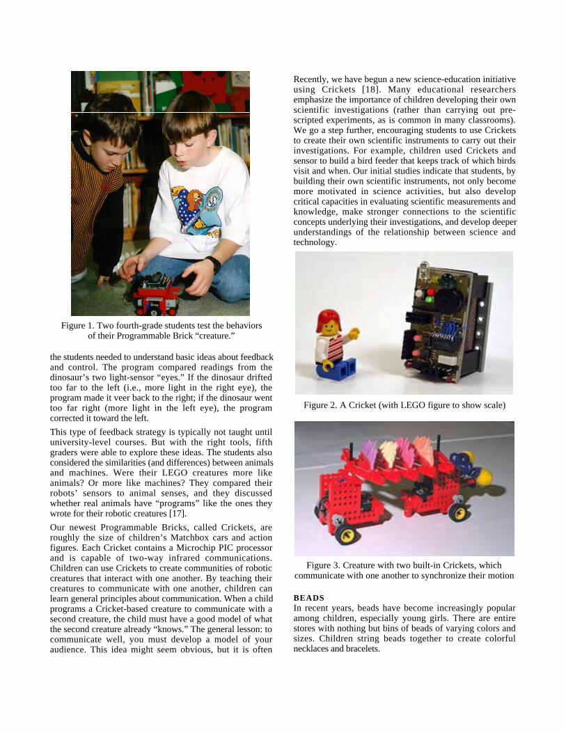
Figure 1. Two fourth-grade students test the behaviorsof their Programmable Brick “creature.”
the students needed to understand basic ideas about feedbackand control. The program compared readings from thedinosaur’s two light-sensor “eyes.” If the dinosaur driftedtoo far to the left (i.e., more light in the right eye), theprogram made it veer back to the right; if the dinosaur wenttoo far right (more light in the left eye), the programcorrected it toward the left.
This type of feedback strategy is typically not taught untiluniversity-level courses. But with the right tools, fifthgraders were able to explore these ideas. The students alsoconsidered the similarities (and differences) between animalsand machines. Were their LEGO creatures more likeanimals? Or more like machines? They compared theirrobots’ sensors to animal senses, and they discussedwhether real animals have “programs” like the ones theywrote for their robotic creatures [17].
Our newest Programmable Bricks, called Crickets, areroughly the size of children’s Matchbox cars and actionfigures. Each Cricket contains a Microchip PIC processorand is capable of two-way infrared communications.Children can use Crickets to create communities of roboticcreatures that interact with one another. By teaching theircreatures to communicate with one another, children canlearn general principles about communication. When a childprograms a Cricket-based creature to communicate with asecond creature, the child must have a good model of whatthe second creature already “knows.” The general lesson: tocommunicate well, you must develop a model of youraudience. This idea might seem obvious, but it is often
p
Recently, we have begun a new science-education initiativeusing Crickets [18]. Many educational researchersemphasize the importance of children developing their ownscientific investigations (rather than carrying out pre-scripted experiments, as is common in many classrooms).We go a step further, encouraging students to use Cricketsto create their own scientific instruments to carry out theirinvestigations. For example, children used Crickets andsensor to build a bird feeder that keeps track of which birdsvisit and when. Our initial studies indicate that students, bybuilding their own scientific instruments, not only becomemore motivated in science activities, but also developcritical capacities in evaluating scientific measurements andknowledge, make stronger connections to the scientificconcepts underlying their investigations, and develop deeperunderstandings of the relationship between science andtechnology.
Figure 2. A Cricket (with LEGO figure to show scale)
Figure 3. Creature with two built-in Crickets, whichcommunicate with one another to synchronize their motion
BEADSIn recent years, beads have become increasingly popularamong children, especially young girls. There are entirestores with nothing but bins of beads of varying colors andsizes. Children string beads together to create colorfulnecklaces and bracelets.
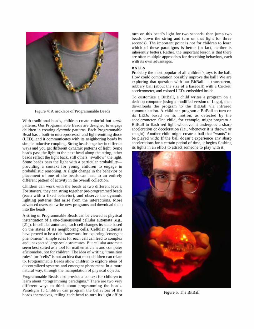
Figure 4. A necklace of Programmable Beads
With traditional beads, children create colorful but staticpatterns. Our Programmable Beads are designed to engagechildren in creating dynamic patterns. Each ProgrammableBead has a built-in microprocessor and light-emitting diode(LED), and it communicates with its neighboring beads bysimple inductive coupling. String beads together in differentways and you get different dynamic patterns of light. Somebeads pass the light to the next bead along the string, otherbeads reflect the light back, still others “swallow” the light.Some beads pass the light with a particular probability—providing a context for young children to engage inprobabilistic reasoning. A slight change in the behavior orplacement of one of the beads can lead to an entirelydifferent pattern of activity in the overall collection.
Children can work with the beads at two different levels.For starters, they can string together pre-programmed beads(each with a fixed behavior), and observe the dynamiclighting patterns that arise from the interactions. Moreadvanced users can write new programs and download theminto the beads.
A string of Programmable Beads can be viewed as physicalinstantiation of a one-dimensional cellular automata (e.g.,[21]). In cellular automata, each cell changes its state basedon the states of its neighboring cells. Cellular automatahave proved to be a rich framework for exploring “emergentphenomena”; simple rules for each cell can lead to complexand unexpected large-scale structures. But cellular automataseem best suited as a tool for mathematicians and computeraficionados, not for children. The idea of writing “transitionrules” for “cells” is not an idea that most children can relateto. Programmable Beads allow children to explore ideas ofdecentralized systems and emergent phenomena in a morenatural way, through the manipulation of physical objects.
Programmable Beads also provide a context for children tolearn about “programming paradigms.” There are two verydifferent ways to think about programming the beads.Paradigm 1: Children can program the behaviors of thebeads themselves, telling each bead to turn its light off or
p g p j p gturn on this bead’s light for two seconds, then jump twobeads down the string and turn on that light for threeseconds). The important point is not for children to learnwhich of these paradigms is better (in fact, neither isinherently better). Rather, the important lesson is that thereare often multiple approaches for describing behaviors, eachwith its own advantages.
BALLSProbably the most popular of all children’s toys is the ball.How could computation possibly improve the ball? We areexploring that question with our BitBall—a transparent,rubbery ball (about the size of a baseball) with a Cricket,accelerometer, and colored LEDs embedded inside.
To customize a BitBall, a child writes a program on adesktop computer (using a modified version of Logo), thendownloads the program to the BitBall via infraredcommunication. A child can program a BitBall to turn onits LEDs based on its motion, as detected by theaccelerometer. One child, for example, might program aBitBall to flash red light whenever it undergoes a sharpacceleration or deceleration (i.e., whenever it is thrown orcaught). Another child might create a ball that “wants” tobe played with: If the ball doesn’t experience any sharpaccelerations for a certain period of time, it begins flashingits lights in an effort to attract someone to play with it.
Figure 5. The BitBall
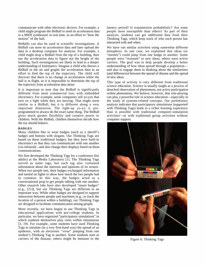
g p gcommunicate with other electronic devices. For example, achild might program the BitBall to send its acceleration datato a MIDI synthesizer in real time, in an effort to “hear themotion” of the ball.
BitBalls can also be used in scientific investigations. ABitBall can store its acceleration data and later upload thedata to a desktop computer for analysis. For example, achild might drop a BitBall from the top of a building, thenuse the acceleration data to figure out the height of thebuilding. Such investigations are likely to lead to a deeperunderstanding of kinematics. Imagine a child who throws aBitBall in the air and graphs the acceleration data in aneffort to find the top of the trajectory. The child willdiscover that there is no change in acceleration while theball is in flight, so it is impossible to determine the top ofthe trajectory from acceleration data alone.
It is important to note that the BitBall is significantlydifferent from most commercial toys with embeddedelectronics. For example, some companies sell yo-yos thatturn on a light while they are moving. That might seemsimilar to a BitBall, but it is different along a veryimportant dimension. The light-up yo-yo is pre-programmed to always do the exact same thing. The BitBallgives much greater flexibility and creative power tochildren. With the BitBall, children themselves decide howthe toy should behave.
BADGESMany children like to wear badges (such as a sheriff’sbadge) and buttons with slogans. Our Thinking Tags arebased on these traditional badges, but they have built-inelectronics so that they can communicate with one another(via infrared)—and also change their displays based on thosecommunications.
We first developed the Thinking Tags for a conference (foradults) at the Media Laboratory [1]. The Thinking Tagsserved as name tags, but each tag also containedinformation about the interests and opinions of its wearer.When two people met, their badges exchanged informationand turned on lights to show how much the two people hadin common. In this way, the badges acted as aconversational prop to get people talking with one another.Other research labs have also developed “smart badges”(e.g., [21]), but our Thinking Tags are different in animportant way: While other badges are designed to supportinteraction between people and machines (e.g., to track thelocation of a person within a building), our Thinking Tagsare designed to facilitate communication among people.
More recently, we have begun to use Thinking Tags ineducational applications with pre-college students. Inparticular, we have organized “participatory simulations” inwhich students themselves play roles within simulations[3, 19]. For example, some students have used ThinkingTags to simulate (in a very first-hand way) the spread of anepidemic, with an electronic “virus” jumping from onestudent’s Thinking Tag to another. Some students start ascarriers of the disease, others might be immune to the
p platency period? Is transmission probabilistic? Are somepeople more susceptible than others? As part of theiranalysis, students can get additional data from theirThinking Tags, which keep track of who each person hasinteracted with and when.
We have run similar activities using somewhat differentmetaphors. In one case, we explained that ideas (or“memes”) could jump from one badge to another. Somepeople were “resistant” to new ideas; others were activecarriers. The goal was to help people develop a betterunderstanding of how ideas spread through a population—and also to engage them in thinking about the similarities(and differences) between the spread of disease and the spreadof new ideas.
This type of activity is very different from traditionalscience education. Science is usually taught as a process ofdetached observation of phenomena, not active participationwithin phenomena. We believe, however, that role-playingcan play a powerful role in science education—especially inthe study of systems-related concepts. Our preliminaryanalysis indicates that participatory simulations (supportedwith Thinking Tags) leads to a richer learning experiencethan is possible with traditional computer-simulationactivities—or with traditional group activities withoutcomputer support.
Figure 6: Thinking Tags
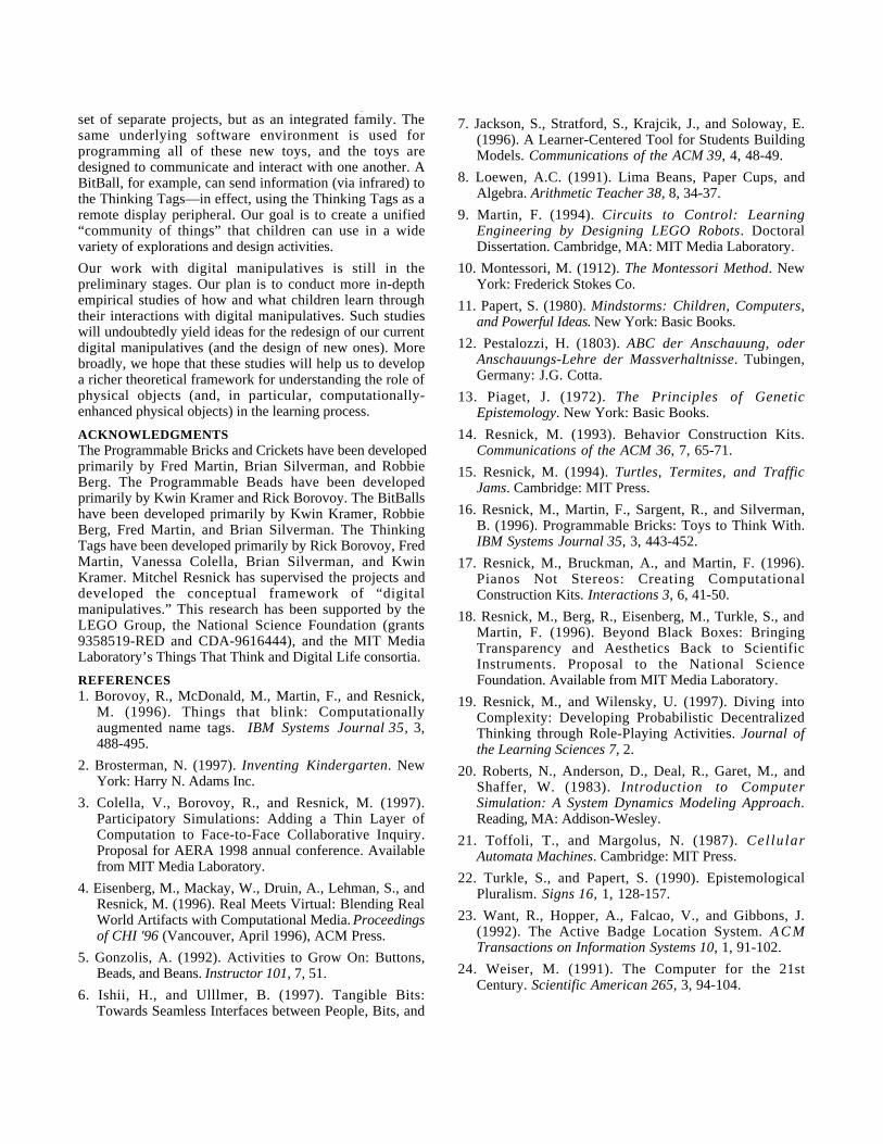
, , , gset of separate projects, but as an integrated family. Thesame underlying software environment is used forprogramming all of these new toys, and the toys aredesigned to communicate and interact with one another. ABitBall, for example, can send information (via infrared) tothe Thinking Tags—in effect, using the Thinking Tags as aremote display peripheral. Our goal is to create a unified“community of things” that children can use in a widevariety of explorations and design activities.
Our work with digital manipulatives is still in thepreliminary stages. Our plan is to conduct more in-depthempirical studies of how and what children learn throughtheir interactions with digital manipulatives. Such studieswill undoubtedly yield ideas for the redesign of our currentdigital manipulatives (and the design of new ones). Morebroadly, we hope that these studies will help us to developa richer theoretical framework for understanding the role ofphysical objects (and, in particular, computationally-enhanced physical objects) in the learning process.
ACKNOWLEDGMENTSThe Programmable Bricks and Crickets have been developedprimarily by Fred Martin, Brian Silverman, and RobbieBerg. The Programmable Beads have been developedprimarily by Kwin Kramer and Rick Borovoy. The BitBallshave been developed primarily by Kwin Kramer, RobbieBerg, Fred Martin, and Brian Silverman. The ThinkingTags have been developed primarily by Rick Borovoy, FredMartin, Vanessa Colella, Brian Silverman, and KwinKramer. Mitchel Resnick has supervised the projects anddeveloped the conceptual framework of “digitalmanipulatives.” This research has been supported by theLEGO Group, the National Science Foundation (grants9358519-RED and CDA-9616444), and the MIT MediaLaboratory’s Things That Think and Digital Life consortia.
REFERENCES1. Borovoy, R., McDonald, M., Martin, F., and Resnick,
M. (1996). Things that blink: Computationallyaugmented name tags. IBM Systems Journal 35, 3,488-495.
2. Brosterman, N. (1997). Inventing Kindergarten. NewYork: Harry N. Adams Inc.
3. Colella, V., Borovoy, R., and Resnick, M. (1997).Participatory Simulations: Adding a Thin Layer ofComputation to Face-to-Face Collaborative Inquiry.Proposal for AERA 1998 annual conference. Availablefrom MIT Media Laboratory.
4. Eisenberg, M., Mackay, W., Druin, A., Lehman, S., andResnick, M. (1996). Real Meets Virtual: Blending RealWorld Artifacts with Computational Media. Proceedingsof CHI '96 (Vancouver, April 1996), ACM Press.
5. Gonzolis, A. (1992). Activities to Grow On: Buttons,Beads, and Beans. Instructor 101, 7, 51.
6. Ishii, H., and Ulllmer, B. (1997). Tangible Bits:Towards Seamless Interfaces between People, Bits, and
7. Jackson, S., Stratford, S., Krajcik, J., and Soloway, E.(1996). A Learner-Centered Tool for Students BuildingModels. Communications of the ACM 39, 4, 48-49.
8. Loewen, A.C. (1991). Lima Beans, Paper Cups, andAlgebra. Arithmetic Teacher 38, 8, 34-37.
9. Martin, F. (1994). Circuits to Control: LearningEngineering by Designing LEGO Robots. DoctoralDissertation. Cambridge, MA: MIT Media Laboratory.
10. Montessori, M. (1912). The Montessori Method. NewYork: Frederick Stokes Co.
11. Papert, S. (1980). Mindstorms: Children, Computers,and Powerful Ideas. New York: Basic Books.
12. Pestalozzi, H. (1803). ABC der Anschauung, oderAnschauungs-Lehre der Massverhaltnisse. Tubingen,Germany: J.G. Cotta.
13. Piaget, J. (1972). The Principles of GeneticEpistemology. New York: Basic Books.
14. Resnick, M. (1993). Behavior Construction Kits.Communications of the ACM 36, 7, 65-71.
15. Resnick, M. (1994). Turtles, Termites, and TrafficJams. Cambridge: MIT Press.
16. Resnick, M., Martin, F., Sargent, R., and Silverman,B. (1996). Programmable Bricks: Toys to Think With.IBM Systems Journal 35, 3, 443-452.
17. Resnick, M., Bruckman, A., and Martin, F. (1996).Pianos Not Stereos: Creating ComputationalConstruction Kits. Interactions 3, 6, 41-50.
18. Resnick, M., Berg, R., Eisenberg, M., Turkle, S., andMartin, F. (1996). Beyond Black Boxes: BringingTransparency and Aesthetics Back to ScientificInstruments. Proposal to the National ScienceFoundation. Available from MIT Media Laboratory.
19. Resnick, M., and Wilensky, U. (1997). Diving intoComplexity: Developing Probabilistic DecentralizedThinking through Role-Playing Activities. Journal ofthe Learning Sciences 7, 2.
20. Roberts, N., Anderson, D., Deal, R., Garet, M., andShaffer, W. (1983). Introduction to ComputerSimulation: A System Dynamics Modeling Approach.Reading, MA: Addison-Wesley.
21. Toffoli, T., and Margolus, N. (1987). CellularAutomata Machines. Cambridge: MIT Press.
22. Turkle, S., and Papert, S. (1990). EpistemologicalPluralism. Signs 16, 1, 128-157.
23. Want, R., Hopper, A., Falcao, V., and Gibbons, J.(1992). The Active Badge Location System. A C MTransactions on Information Systems 10, 1, 91-102.
24. Weiser, M. (1991). The Computer for the 21stCentury. Scientific American 265, 3, 94-104.

p g