Embed Size (px)
Citation preview
WECC Data Preparation Manual
for Interconnection-wide Cases
Applicable to the 2019 Base Case Compilation Schedule
System Data Work Group
Data Subcommittee
155 North 400 West, Suite 200
Salt Lake City, Utah 84103-1114
WECC Data Preparation Manual 2
W E S T E R N E L E C T R I C I T Y C O O R D I N A T I N G C O U N C I L
Table of Contents
Introduction ...................................................................................................................................... 1
Definitions ........................................................................................................................................ 1
General Data Requirements and Reporting Procedures ..................................................................... 2
Data Requirements ................................................................................................................................. 2
Reporting Procedures ............................................................................................................................. 3
Steady-State Data Requirements ....................................................................................................... 3
AC and DC Buses ..................................................................................................................................... 4
Generation .............................................................................................................................................. 7
AC Transmission Lines ........................................................................................................................... 12
Connectors ............................................................................................................................................ 15
Transformers ......................................................................................................................................... 17
Fixed-Shunt Reactive Elements............................................................................................................. 22
Controlled Shunt Reactive Devices ....................................................................................................... 23
Loads ..................................................................................................................................................... 26
DC Transmission Lines ........................................................................................................................... 28
Area Interchange Schedules ................................................................................................................. 29
Master Tie-Line File ............................................................................................................................... 30
AC Substations ...................................................................................................................................... 31
Dynamic Data Requirements ........................................................................................................... 31
Generation Requirements .................................................................................................................... 33
Load Requirements ............................................................................................................................... 33
Underfrequency Load Shedding (UFLS) ................................................................................................ 34
Undervoltage Load Shedding (UVLS) .................................................................................................... 34
Relays .................................................................................................................................................... 34
Back-to-Back DC Ties ............................................................................................................................. 34
DC Lines, SVC and D-VAr systems ......................................................................................................... 34
Remedial Action Scheme and Associated Contingency Data ............................................................. 35
WECC Data Preparation Manual 3
W E S T E R N E L E C T R I C I T Y C O O R D I N A T I N G C O U N C I L
Appendix 1 – Late Data Procedure ................................................................................................... 37
Data Submitter and Staff Responsibilities ............................................................................................ 37
Actions to Take ...................................................................................................................................... 38
Backfitting of Late Data ......................................................................................................................... 38
Appendix 2 – Area, Zone and Bus Number Assignments................................................................... 39
Southwest Region ................................................................................................................................. 39
Southern California Region ................................................................................................................... 40
Northern California Region ................................................................................................................... 41
Northwest Region ................................................................................................................................. 42
Canadian Region ................................................................................................................................... 43
Central Region ....................................................................................................................................... 43
Eastern Region ...................................................................................................................................... 44
Temporary Assignment ......................................................................................................................... 44
Miscellaneous Assignment ................................................................................................................... 45
WECC Data Preparation Manual 1
W E S T E R N E L E C T R I C I T Y C O O R D I N A T I N G C O U N C I L
Introduction
The WECC Data Preparation Manual (DPM) is intended to provide an outline of data requirements and
reporting procedures necessary for Data Submitters to support creation of Interconnection-wide cases
for power flow and dynamic data.
Interconnection-wide cases are used to perform Near-Term and Long-Term Transmission Planning
studies (seasonal Operating Transfer Capability (OTC) studies, WECC path rating studies, and regional-
and local-area studies etc.). Following the data requirement and reporting procedures, as specified in
the DPM, will help WECC meet the needs with the creation of Interconnection-wide cases. .
This DPM may be used by WECC members and any other entities owning/operating facilities in the
Western Interconnection. The System Data Work Group (SDWG), which reports to the Data
Subcommittee (DS), is responsible for maintaining the DPM with oversight from the DS and other
Reliability Assessment Committee (RAC) subcommittees. Data Submitters are responsible for making
data and models available to WECC that accurately represent facilities for which they have been
designated as the Data Submitter. WECC staff is responsible for collecting, archiving, modeling and
making available, solved Interconnection-wide cases for use by WECC members and others that have
met the WECC data security requirements.
Navigating the electronic version of the DPM:
Internal document hyperlinks: Throughout this DPM, there are many references to internal supporting
information. These internal hyperlinks are configured such that when you see a reference that begins
with “See” or “Refer to” followed by text enclosed with double quotes. Mouse over that text and you
will be given the option of following the link to the supporting section of this document.
Definitions
Area: An Area is a subset of the Western Interconnection-wide case composed of generators and
connected contiguous elements to assist in the coordinated development of a WECC Interconnection-
wide case. The Areas are defined by the SDWG and listed in “Appendix 2 – Area, Zone and Bus Number
Assignments.”
Balancing Coordinator: Balancing Coordinator (not a NERC functional entity) is a Data Submitter who
submits interchange schedules between Areas in coordination with adjacent Balancing Coordinators.
Data Submitter: Data Submitter (not a NERC functional entity) refers to a responsible entity that
provides the data detailed in the DPM to support the creation of Interconnection-wide cases.
WECC Data Preparation Manual 2
W E S T E R N E L E C T R I C I T Y C O O R D I N A T I N G C O U N C I L
Generation Netting: The representation of a generator(s) through the modeling of a load element with
the real and reactive power requirements set to the net of generation and load. Alternatively,
Generation Netting may be the representation of a generator(s) using a load element with a negative
Real Power demand setting. Generation Netting may be used only in dynamic simulations by including
the Generator element in the Netting section of the Positive Sequence Load Flow (PSLF) DYD file for a
given WECC Base Case.
Interconnection-wide Case(s): Models representing the entire Western Interconnection, which may
include WECC Base Cases.
Master Dynamics File (MDF): File in PSLF DYD format containing dynamic data for use in the
compilation of all WECC Base Cases.
Master Tie-Line File: File in PSLF EPC format containing steady-state data used to model elements of
the existing Western Interconnection that represent the tie-lines between Areas and other modeling
data that pertains to multiple Areas.
Planned Facilities: Facilities that have not yet met their in-service date at the time data is submitted
for inclusion in a base case. See the “General Data Requirements and Reporting Procedures” section.
PSLF: General Electric’s Positive Sequence Load Flow software tool for electrical transmission analysis.
PSS®E: Siemens PTI’s Power System Simulator for Engineering software tool for electrical transmission
analysis.
WECC Base Case(s): A set of solved and solvable steady-state and dynamic data representing a specific
operating scenario of the Western Interconnection compiled by WECC staff, using the models and data
provided by the Data Submitters.
WECC Staff: Employees of WECC who participate in the modeling and coordination of steady-state and
dynamic data for use in creating WECC Interconnection-wide cases.
General Data Requirements and Reporting Procedures
The data requirements and reporting procedures included in this Data Preparation Manual are
intended to provide guidance for Data Submitters to support creation of Interconnection-wide cases.
Data Submitters should develop processes to obtain and compile the requested data.
Data Requirements
Data format and content requirements for the development of Interconnection-wide cases are broken
into two data types: steady state and dynamic. Sections IV and V address each data type respectively.
An additional data requirements section is provided to address the modeling of contingencies and
remedial action schemes.
WECC Data Preparation Manual 3
W E S T E R N E L E C T R I C I T Y C O O R D I N A T I N G C O U N C I L
In consideration of including Planned Facilities in submitted data, the following guidelines should be
followed:
• the facilities are expected be in-service on the scheduled base case posting date;
• the facilities are expected to be in-service in the month and year represented in the case; or
• the facilities are required to support proposed generation facilities that are modeled in-service
in the case.
All data must be the best available data.
Generator dynamic data resulting from equipment testing should be provided if it is available. If test
data is not available, design data should be provided. If design data is not available, generic Dynamic
data should be provided. In-service equipment should be supported by test data while far-term
planned equipment may be modeled using generic dynamic data.
Reporting Procedures
The schedule for Data Submitters to follow is specified in the request for data submission from WECC
staff. A preliminary schedule for providing data for Interconnection-wide case creation is also included
in the Base Case Compilation Schedule.
Steady-State Data Requirements
To provide consistency in data submittals and help avoid potential solution problems, follow the
guidelines below to the maximum extent possible. However, WECC recognizes deviations from the
guidelines may occasionally be needed. For these situations, Data Submitters are requested to provide
the SDWG and Modeling and Validation Work Group (MVWG) with the rationale for exceptions. The
Interconnection-wide base cases include the following steady-state data requirements:
• With the exception of collector-based generation such as wind and solar, all Bulk Electric
System (BES) elements, as presently defined by NERC, within the Western Interconnection shall
be represented in WECC Base Cases without equivalencing.
• Non-Bulk Electric System elements may also be included in WECC Base Cases and follow the
data submittal requirements in this DPM. Any equivalencing of non-Bulk Electric System
elements shall be modeled to yield almost identical performance of a full representation in
both steady state and dynamic analysis.
• Non-Bulk Electric System elements shall be included if they have significant interaction with BES
elements. Non-Bulk Electric System elements that may have a significant interaction with BES
elements may exhibit any of the following characteristics:
o Facilities that are operated at or above 50 kV
WECC Data Preparation Manual 4
W E S T E R N E L E C T R I C I T Y C O O R D I N A T I N G C O U N C I L
o Facilities that are operated in parallel with BES elements
o Facilities with connected individual generation resources >=10 MVA or aggregate
generation resources >=20 MVA
o Facilities with connected reactive resources >=10 Mvar
• Non-Bulk Electric System Local Networks and Radial Systems that feed only load or
parallel/looped systems that are normally operated in a radial configuration could generally be
excluded from modeling.
• Steady-state power flow data submitted to WECC shall represent the existing Bulk Electric
System elements plus planned transmission and generation facilities as described elsewhere in
this document and as deemed appropriate by the Data Submitter.
• Paths defined in the WECC Path Rating Catalog shall be modeled to include all elements
consistent with the path definition.
• Data fields that are strings shall not contain commas, single quotes, double quotes, or
apostrophes.
• Key element identifiers (e.g., number, name, base voltage, ID) that indicate an element
representing the same equipment shall be consistent between base cases.
o Devices with alpha characters shall consistently use either uppercase or lowercase IDs.
o Bus names with alpha characters shall consistently be either uppercase or lowercase.
• Uniqueness shall not depend on names and IDs being case sensitive.
• The requested data is listed below in the tables of data requirements. Any description provided
for the field shall be followed.
• Bus naming guideline: Although the criterion for bus names is that ‘Bus names shall be unique
within the same Base Voltage class,’ bus names should be the same for all equipment located in
the same vicinity. For example, two substations that are in different Areas could both be named
“Midway.” Names could be set to “MIDWAY” at one location, and to “MDWAY” at the other.
The SDWG strongly suggests that naming of new buses added to the model adhere to the
stated guideline. It recommends, but it is not mandatory, to eliminate spaces in bus names and
substitute underscore characters instead. It is the responsibility of the Data Submitter adding
the bus information to assure there is no name duplication.
AC and DC Buses
General Requirements:
WECC Data Preparation Manual 5
W E S T E R N E L E C T R I C I T Y C O O R D I N A T I N G C O U N C I L
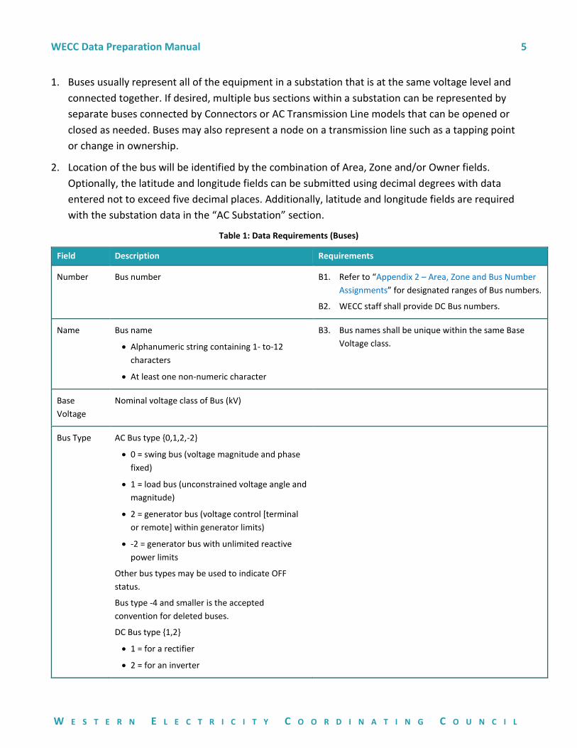
1. Buses usually represent all of the equipment in a substation that is at the same voltage level and
connected together. If desired, multiple bus sections within a substation can be represented by
separate buses connected by Connectors or AC Transmission Line models that can be opened or
closed as needed. Buses may also represent a node on a transmission line such as a tapping point
or change in ownership.
2. Location of the bus will be identified by the combination of Area, Zone and/or Owner fields.
Optionally, the latitude and longitude fields can be submitted using decimal degrees with data
entered not to exceed five decimal places. Additionally, latitude and longitude fields are required
with the substation data in the “AC Substation” section.
Table 1: Data Requirements (Buses)
Field Description Requirements
Number Bus number
B1. Refer to “Appendix 2 – Area, Zone and Bus Number
Assignments” for designated ranges of Bus numbers.
B2. WECC staff shall provide DC Bus numbers.
Name Bus name
• Alphanumeric string containing 1- to-12
characters
• At least one non-numeric character
B3. Bus names shall be unique within the same Base
Voltage class.
Base
Voltage
Nominal voltage class of Bus (kV)
Bus Type AC Bus type {0,1,2,-2}
• 0 = swing bus (voltage magnitude and phase
fixed)
• 1 = load bus (unconstrained voltage angle and
magnitude)
• 2 = generator bus (voltage control [terminal
or remote] within generator limits)
• -2 = generator bus with unlimited reactive
power limits
Other bus types may be used to indicate OFF
status.
Bus type -4 and smaller is the accepted
convention for deleted buses.
DC Bus type {1,2}
• 1 = for a rectifier
• 2 = for an inverter
WECC Data Preparation Manual 6
W E S T E R N E L E C T R I C I T Y C O O R D I N A T I N G C O U N C I L
Field Description Requirements
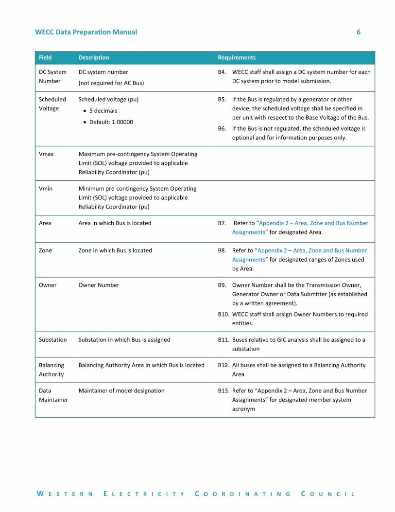
DC System
Number
DC system number
(not required for AC Bus)
B4. WECC staff shall assign a DC system number for each
DC system prior to model submission.
Scheduled
Voltage
Scheduled voltage (pu)
• 5 decimals
• Default: 1.00000
B5. If the Bus is regulated by a generator or other
device, the scheduled voltage shall be specified in
per unit with respect to the Base Voltage of the Bus.
B6. If the Bus is not regulated, the scheduled voltage is
optional and for information purposes only.
Vmax Maximum pre-contingency System Operating
Limit (SOL) voltage provided to applicable
Reliability Coordinator (pu)
Vmin Minimum pre-contingency System Operating
Limit (SOL) voltage provided to applicable
Reliability Coordinator (pu)
Area Area in which Bus is located
B7. Refer to “Appendix 2 – Area, Zone and Bus Number
Assignments” for designated Area.
Zone Zone in which Bus is located
B8. Refer to “Appendix 2 – Area, Zone and Bus Number
Assignments” for designated ranges of Zones used
by Area.
Owner Owner Number
B9. Owner Number shall be the Transmission Owner,
Generator Owner or Data Submitter (as established
by a written agreement).
B10. WECC staff shall assign Owner Numbers to required
entities.
Substation Substation in which Bus is assigned B11. Buses relative to GIC analysis shall be assigned to a
substation
Balancing
Authority
Balancing Authority Area in which Bus is located B12. All buses shall be assigned to a Balancing Authority
Area
Data
Maintainer
Maintainer of model designation B13. Refer to “Appendix 2 – Area, Zone and Bus Number
Assignments” for designated member system
acronym
WECC Data Preparation Manual 7
W E S T E R N E L E C T R I C I T Y C O O R D I N A T I N G C O U N C I L
Generation
1. Generators selected for Area Slack Control, including the system slack, shall meet the same
technical requirements as selecting generators for automatic generation control (AGC) of a
Balancing Authority Area. Generators selected for AGC typically have the following attributes:
a. Changes in MW output cause small changes in generator angle (suggested; dAngle/dP <
0.15 degrees/MW).
b. Generation is dispatchable.
c. Maximum MW output typically greater than 100 MW.
d. Unit is expected to be in service for time frame represented in the WECC base case.
2. Modeling of generators shall comply with the following:
a. If the individual-generator-unit capacity is 10 MVA or larger and the generator is connected
to the WECC transmission system at 60 kV or higher, then submit steady-state data and
dynamics data for each generator.
b. If the aggregated-generator-unit capacity is 20 MVA or larger, the generators are connected
to the WECC transmission system at 60 kV or higher, and it is not a collector-based
generation facility− then submit steady-state data and dynamics data for each generator.
(Wind and solar farms are examples of collector-based generation facilities.)
c. If the aggregated-generation capacity is 20 MVA or larger, is connected to the WECC
transmission system at 60 kV or higher, and is a collector-based generation facility, then
steady-state data and dynamics data should be submitted for the aggregated generation
capacity as a single-unit generator model.
d. Generating facilities without DYD data shall be netted in the DYD file and have their Non-
Conforming Load Flag set appropriately. Steady-state and dynamic generator data shall be
consistent.
3. Synchronous motors 10 MVA and larger shall be modeled as individual machines, using a
generator model with negative Real Power output and constant Reactive Power (Q) output.
4. Induction motors shall be modeled as a load with the intent of using an induction motor model
(MOTORW).
5. Synchronous condensers shall be modeled individually using a generator model.
6. Generator step-up transformers shall be modeled explicitly; therefore, they shall not be modeled
using the internal generator step-up transformer feature of a generator model. All related
parameters shall be set to the default values. See “Data Requirements (Transformers).”
7. Station service loads (ID = ‘SS’) shall be represented explicitly as separate loads on the generator
bus. See “Data Requirements (Loads).”
WECC Data Preparation Manual 8
W E S T E R N E L E C T R I C I T Y C O O R D I N A T I N G C O U N C I L
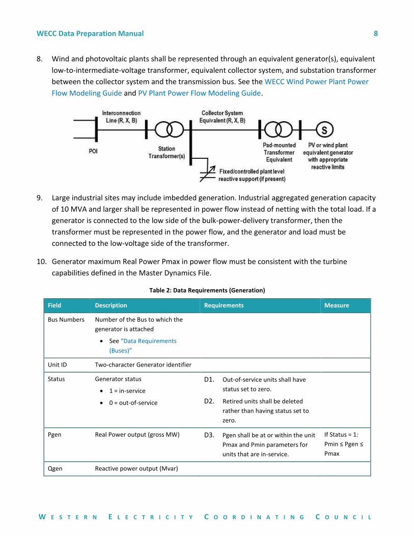
8. Wind and photovoltaic plants shall be represented through an equivalent generator(s), equivalent
low-to-intermediate-voltage transformer, equivalent collector system, and substation transformer
between the collector system and the transmission bus. See the WECC Wind Power Plant Power
Flow Modeling Guide and PV Plant Power Flow Modeling Guide.
9. Large industrial sites may include imbedded generation. Industrial aggregated generation capacity
of 10 MVA and larger shall be represented in power flow instead of netting with the total load. If a
generator is connected to the low side of the bulk-power-delivery transformer, then the
transformer must be represented in the power flow, and the generator and load must be
connected to the low-voltage side of the transformer.
10. Generator maximum Real Power Pmax in power flow must be consistent with the turbine
capabilities defined in the Master Dynamics File.
Table 2: Data Requirements (Generation)
Field Description Requirements Measure
Bus Numbers Number of the Bus to which the
generator is attached
• See “Data Requirements
(Buses)”
Unit ID Two-character Generator identifier
Status Generator status
• 1 = in-service
• 0 = out-of-service
D1. Out-of-service units shall have
status set to zero.
D2. Retired units shall be deleted
rather than having status set to
zero.
Pgen Real Power output (gross MW) D3. Pgen shall be at or within the unit
Pmax and Pmin parameters for
units that are in-service.
If Status = 1:
Pmin ≤ Pgen ≤
Pmax
Qgen Reactive power output (Mvar)
WECC Data Preparation Manual 9
W E S T E R N E L E C T R I C I T Y C O O R D I N A T I N G C O U N C I L
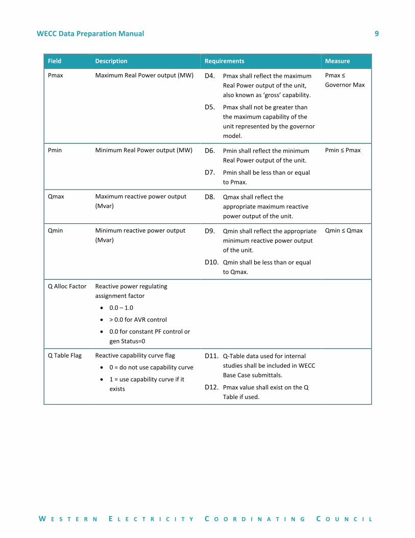
Field Description Requirements Measure
Pmax Maximum Real Power output (MW) D4. Pmax shall reflect the maximum
Real Power output of the unit,
also known as ‘gross’ capability.
D5. Pmax shall not be greater than
the maximum capability of the
unit represented by the governor
model.
Pmax ≤
Governor Max
Pmin Minimum Real Power output (MW) D6. Pmin shall reflect the minimum
Real Power output of the unit.
D7. Pmin shall be less than or equal
to Pmax.
Pmin ≤ Pmax
Qmax Maximum reactive power output
(Mvar)
D8. Qmax shall reflect the
appropriate maximum reactive
power output of the unit.
Qmin Minimum reactive power output
(Mvar)
D9. Qmin shall reflect the appropriate
minimum reactive power output
of the unit.
D10. Qmin shall be less than or equal
to Qmax.
Qmin ≤ Qmax
Q Alloc Factor Reactive power regulating
assignment factor
• 0.0 – 1.0
• > 0.0 for AVR control
• 0.0 for constant PF control or
gen Status=0
Q Table Flag Reactive capability curve flag
• 0 = do not use capability curve
• 1 = use capability curve if it
exists
D11. Q-Table data used for internal
studies shall be included in WECC
Base Case submittals.
D12. Pmax value shall exist on the Q
Table if used.
WECC Data Preparation Manual 10
W E S T E R N E L E C T R I C I T Y C O O R D I N A T I N G C O U N C I L
Field Description Requirements Measure
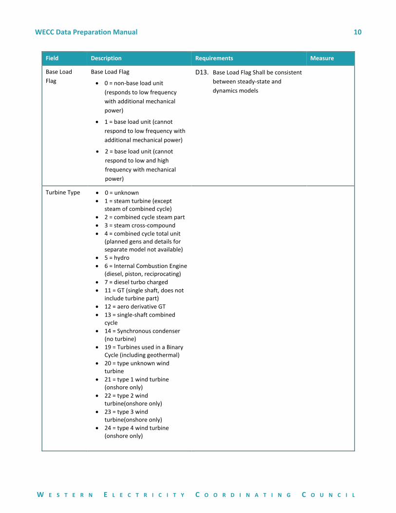
Base Load
Flag
Base Load Flag
• 0 = non-base load unit
(responds to low frequency
with additional mechanical
power)
• 1 = base load unit (cannot
respond to low frequency with
additional mechanical power)
• 2 = base load unit (cannot
respond to low and high
frequency with mechanical
power)
D13. Base Load Flag Shall be consistent
between steady-state and
dynamics models
Turbine Type • 0 = unknown
• 1 = steam turbine (except steam of combined cycle)
• 2 = combined cycle steam part
• 3 = steam cross-compound
• 4 = combined cycle total unit (planned gens and details for separate model not available)
• 5 = hydro
• 6 = Internal Combustion Engine (diesel, piston, reciprocating)
• 7 = diesel turbo charged
• 11 = GT (single shaft, does not include turbine part)
• 12 = aero derivative GT
• 13 = single-shaft combined cycle
• 14 = Synchronous condenser (no turbine)
• 19 = Turbines used in a Binary Cycle (including geothermal)
• 20 = type unknown wind turbine
• 21 = type 1 wind turbine (onshore only)
• 22 = type 2 wind turbine(onshore only)
• 23 = type 3 wind turbine(onshore only)
• 24 = type 4 wind turbine (onshore only)
WECC Data Preparation Manual 11
W E S T E R N E L E C T R I C I T Y C O O R D I N A T I N G C O U N C I L
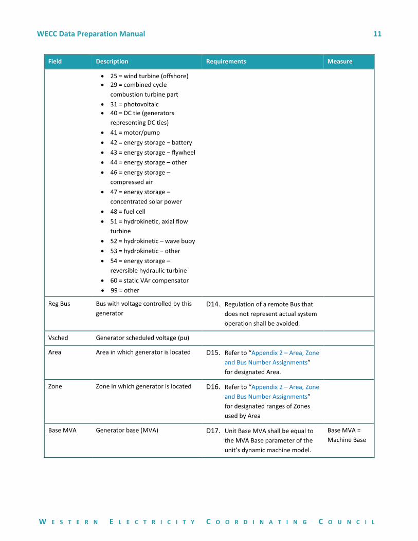
Field Description Requirements Measure
• 25 = wind turbine (offshore)
• 29 = combined cycle
combustion turbine part
• 31 = photovoltaic
• 40 = DC tie (generators
representing DC ties)
• 41 = motor/pump
• 42 = energy storage − battery
• 43 = energy storage − flywheel
• 44 = energy storage – other
• 46 = energy storage –
compressed air
• 47 = energy storage –
concentrated solar power
• 48 = fuel cell
• 51 = hydrokinetic, axial flow
turbine
• 52 = hydrokinetic – wave buoy
• 53 = hydrokinetic − other
• 54 = energy storage –
reversible hydraulic turbine
• 60 = static VAr compensator
• 99 = other
Reg Bus Bus with voltage controlled by this
generator
D14. Regulation of a remote Bus that
does not represent actual system
operation shall be avoided.
Vsched Generator scheduled voltage (pu)
Area Area in which generator is located D15. Refer to “Appendix 2 – Area, Zone
and Bus Number Assignments”
for designated Area.
Zone Zone in which generator is located D16. Refer to “Appendix 2 – Area, Zone
and Bus Number Assignments”
for designated ranges of Zones
used by Area
Base MVA Generator base (MVA) D17. Unit Base MVA shall be equal to
the MVA Base parameter of the
unit’s dynamic machine model.
Base MVA =
Machine Base
WECC Data Preparation Manual 12
W E S T E R N E L E C T R I C I T Y C O O R D I N A T I N G C O U N C I L
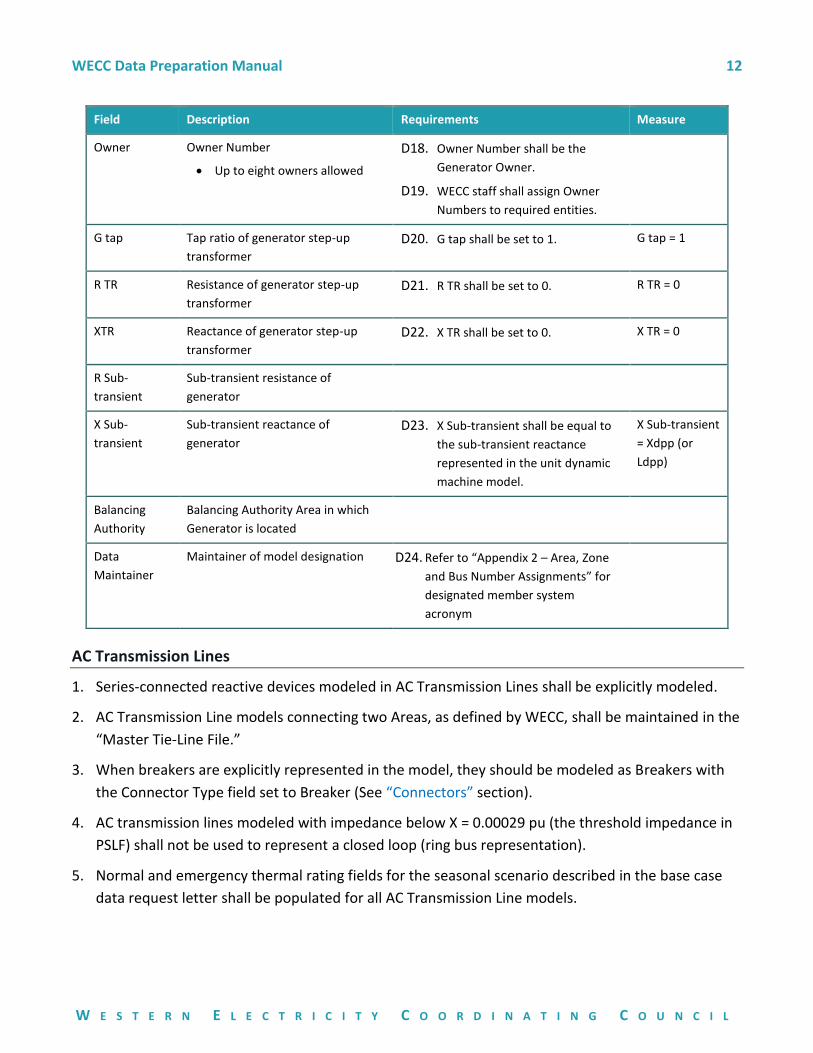
Field Description Requirements Measure
Owner Owner Number
• Up to eight owners allowed
D18. Owner Number shall be the
Generator Owner.
D19. WECC staff shall assign Owner
Numbers to required entities.
G tap Tap ratio of generator step-up
transformer
D20. G tap shall be set to 1. G tap = 1
R TR Resistance of generator step-up
transformer
D21. R TR shall be set to 0. R TR = 0
XTR Reactance of generator step-up
transformer
D22. X TR shall be set to 0. X TR = 0
R Sub-
transient
Sub-transient resistance of
generator
X Sub-
transient
Sub-transient reactance of
generator
D23. X Sub-transient shall be equal to
the sub-transient reactance
represented in the unit dynamic
machine model.
X Sub-transient
= Xdpp (or
Ldpp)
Balancing
Authority
Balancing Authority Area in which
Generator is located
Data
Maintainer
Maintainer of model designation D24. Refer to “Appendix 2 – Area, Zone
and Bus Number Assignments” for
designated member system
acronym
AC Transmission Lines
1. Series-connected reactive devices modeled in AC Transmission Lines shall be explicitly modeled.
2. AC Transmission Line models connecting two Areas, as defined by WECC, shall be maintained in the
“Master Tie-Line File.”
3. When breakers are explicitly represented in the model, they should be modeled as Breakers with
the Connector Type field set to Breaker (See “Connectors” section).
4. AC transmission lines modeled with impedance below X = 0.00029 pu (the threshold impedance in
PSLF) shall not be used to represent a closed loop (ring bus representation).
5. Normal and emergency thermal rating fields for the seasonal scenario described in the base case
data request letter shall be populated for all AC Transmission Line models.
WECC Data Preparation Manual 13
W E S T E R N E L E C T R I C I T Y C O O R D I N A T I N G C O U N C I L
6. PSS®E base case data includes only three facility ratings for transmission lines. Ratings 1 and 2 are
used for seasonal normal and emergency ratings corresponding to the season of the case. Rating 3
is used for various other purposes. If directed, WECC staff will move ratings 1 and 2 into the
appropriate seasonal ratings columns for the PSLF version of the base case being developed.
7. Line-connected transformers shall not be modeled using the internal line-connected transformer
feature of a transmission line model; all related parameters shall be set to the default values. See
“Data Requirements (Transformers).”
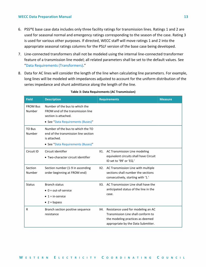
8. Data for AC lines will consider the length of the line when calculating line parameters. For example,
long lines will be modeled with impedances adjusted to account for the uniform distribution of the
series impedance and shunt admittance along the length of the line.
Table 3: Data Requirements (AC Transmission)
Field Description Requirements Measure
FROM Bus
Number
Number of the bus to which the
FROM end of the transmission line
section is attached.
• See “Data Requirements (Buses)”
TO Bus
Number
Number of the bus to which the TO
end of the transmission line section
is attached.
• See “Data Requirements (Buses)”
Circuit ID Circuit identifier
• Two-character circuit identifier
X1. AC Transmission Line modeling
equivalent circuits shall have Circuit
ID set to ‘99’ or ‘EQ.’
Section
Number
Section number (1-9 in ascending
order beginning at FROM end)
X2. AC Transmission Line with multiple
sections shall number the sections
consecutively, starting with ‘1.’
Status Branch status
• 0 = out-of-service
• 1 = in-service
• 2 = bypass
X3. AC Transmission Line shall have the
anticipated status of the line in the
case.
R Branch section positive sequence
resistance
X4. Resistance used for modeling an AC
Transmission Line shall conform to
the modeling practices as deemed
appropriate by the Data Submitter.
WECC Data Preparation Manual 14
W E S T E R N E L E C T R I C I T Y C O O R D I N A T I N G C O U N C I L
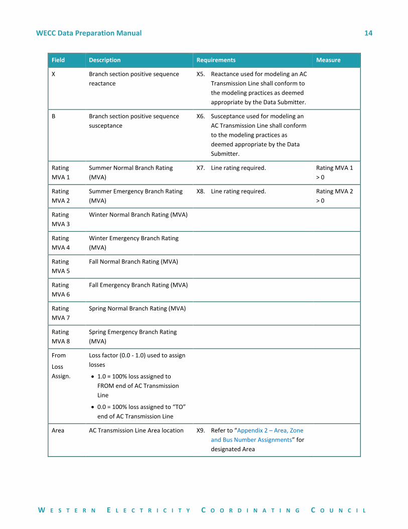
Field Description Requirements Measure
X Branch section positive sequence
reactance
X5. Reactance used for modeling an AC
Transmission Line shall conform to
the modeling practices as deemed
appropriate by the Data Submitter.
B Branch section positive sequence
susceptance
X6. Susceptance used for modeling an
AC Transmission Line shall conform
to the modeling practices as
deemed appropriate by the Data
Submitter.
Rating
MVA 1
Summer Normal Branch Rating
(MVA)
X7. Line rating required. Rating MVA 1
> 0
Rating
MVA 2
Summer Emergency Branch Rating
(MVA)
X8. Line rating required. Rating MVA 2
> 0
Rating
MVA 3
Winter Normal Branch Rating (MVA)
Rating
MVA 4
Winter Emergency Branch Rating
(MVA)
Rating
MVA 5
Fall Normal Branch Rating (MVA)
Rating
MVA 6
Fall Emergency Branch Rating (MVA)
Rating
MVA 7
Spring Normal Branch Rating (MVA)
Rating
MVA 8
Spring Emergency Branch Rating
(MVA)
From
Loss
Assign.
Loss factor (0.0 - 1.0) used to assign
losses
• 1.0 = 100% loss assigned to
FROM end of AC Transmission
Line
• 0.0 = 100% loss assigned to “TO”
end of AC Transmission Line
Area AC Transmission Line Area location X9. Refer to “Appendix 2 – Area, Zone
and Bus Number Assignments” for
designated Area
WECC Data Preparation Manual 15
W E S T E R N E L E C T R I C I T Y C O O R D I N A T I N G C O U N C I L
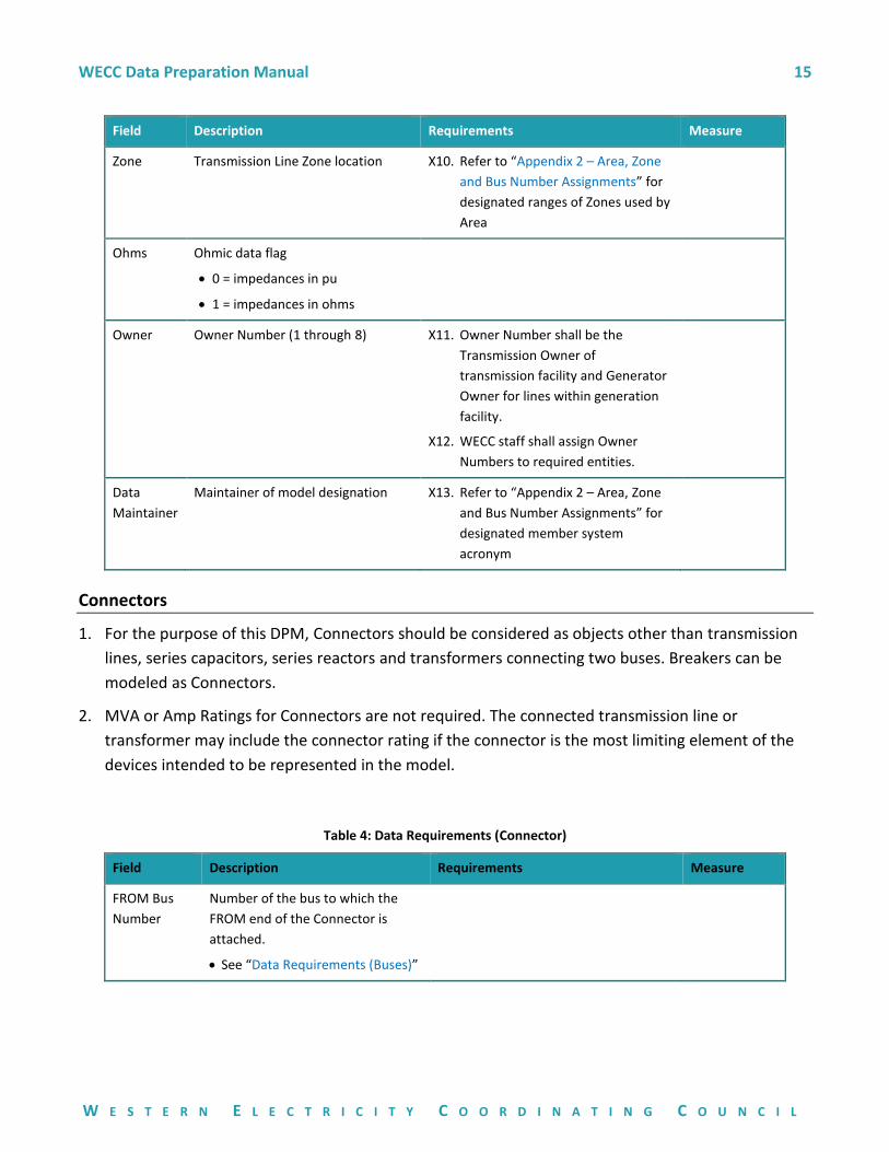
Field Description Requirements Measure
Zone Transmission Line Zone location X10. Refer to “Appendix 2 – Area, Zone
and Bus Number Assignments” for
designated ranges of Zones used by
Area
Ohms Ohmic data flag
• 0 = impedances in pu
• 1 = impedances in ohms
Owner Owner Number (1 through 8) X11. Owner Number shall be the
Transmission Owner of
transmission facility and Generator
Owner for lines within generation
facility.
X12. WECC staff shall assign Owner
Numbers to required entities.
Data
Maintainer
Maintainer of model designation X13. Refer to “Appendix 2 – Area, Zone
and Bus Number Assignments” for
designated member system
acronym
Connectors
1. For the purpose of this DPM, Connectors should be considered as objects other than transmission
lines, series capacitors, series reactors and transformers connecting two buses. Breakers can be
modeled as Connectors.
2. MVA or Amp Ratings for Connectors are not required. The connected transmission line or
transformer may include the connector rating if the connector is the most limiting element of the
devices intended to be represented in the model.
Table 4: Data Requirements (Connector)
Field Description Requirements Measure
FROM Bus
Number
Number of the bus to which the
FROM end of the Connector is
attached.
• See “Data Requirements (Buses)”
WECC Data Preparation Manual 16
W E S T E R N E L E C T R I C I T Y C O O R D I N A T I N G C O U N C I L
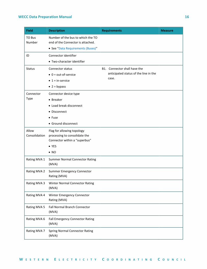
Field Description Requirements Measure
TO Bus
Number
Number of the bus to which the TO
end of the Connector is attached.
• See “Data Requirements (Buses)”
ID Connector identifier
• Two-character identifier
Status Connector status
• 0 = out-of-service
• 1 = in-service
• 2 = bypass
B1. Connector shall have the
anticipated status of the line in the
case.
Connector
Type
Connector device type
• Breaker
• Load break disconnect
• Disconnect
• Fuse
• Ground disconnect
Allow
Consolidation
Flag for allowing topology
processing to consolidate the
Connector within a “superbus”
• YES
• NO
Rating MVA 1 Summer Normal Connector Rating
(MVA)
Rating MVA 2 Summer Emergency Connector
Rating (MVA)
Rating MVA 3 Winter Normal Connector Rating
(MVA)
Rating MVA 4 Winter Emergency Connector
Rating (MVA)
Rating MVA 5 Fall Normal Branch Connector
(MVA)
Rating MVA 6 Fall Emergency Connector Rating
(MVA)
Rating MVA 7 Spring Normal Connector Rating
(MVA)
WECC Data Preparation Manual 17
W E S T E R N E L E C T R I C I T Y C O O R D I N A T I N G C O U N C I L
Field Description Requirements Measure
Rating MVA 8 Spring Emergency Connector Rating
(MVA)
Data
Maintainer
Maintainer of model designation B2. Refer to “Appendix 2 – Area, Zone
and Bus Number Assignments” for
designated member system
acronym
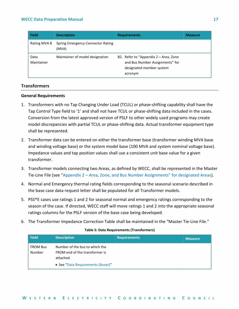
Transformers
General Requirements
1. Transformers with no Tap Changing Under Load (TCUL) or phase-shifting capability shall have the
Tap Control Type field to ‘1’ and shall not have TCUL or phase-shifting data included in the cases.
Conversion from the latest approved version of PSLF to other widely used programs may create
model discrepancies with partial TCUL or phase-shifting data. Actual transformer equipment type
shall be represented.
2. Transformer data can be entered on either the transformer base (transformer winding MVA base
and winding voltage base) or the system model base (100 MVA and system nominal voltage base).
Impedance values and tap position values shall use a consistent unit base value for a given
transformer.
3. Transformer models connecting two Areas, as defined by WECC, shall be represented in the Master
Tie-Line File (see “Appendix 2 – Area, Zone, and Bus Number Assignments” for designated Areas).
4. Normal and Emergency thermal rating fields corresponding to the seasonal scenario described in
the base case data request letter shall be populated for all Transformer models.
5. PSS®E cases use ratings 1 and 2 for seasonal normal and emergency ratings corresponding to the
season of the case. If directed, WECC staff will move ratings 1 and 2 into the appropriate seasonal
ratings columns for the PSLF version of the base case being developed.
6. The Transformer Impedance Correction Table shall be maintained in the “Master Tie-Line File.”
Table 5: Data Requirements (Transformers)
Field Description Requirements Measure
FROM Bus
Number
Number of the bus to which the
FROM end of the transformer is
attached.
• See “Data Requirements (Buses)”
WECC Data Preparation Manual 18
W E S T E R N E L E C T R I C I T Y C O O R D I N A T I N G C O U N C I L
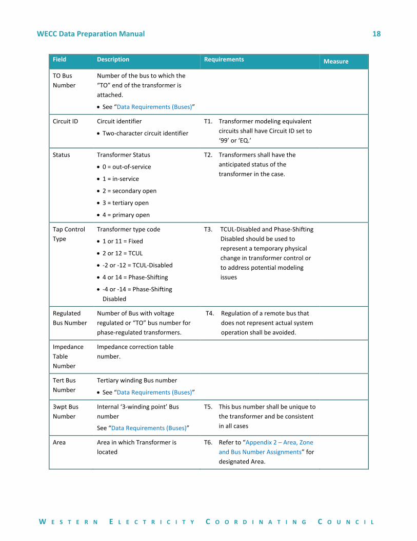
Field Description Requirements Measure
TO Bus
Number
Number of the bus to which the
“TO” end of the transformer is
attached.
• See “Data Requirements (Buses)”
Circuit ID Circuit identifier
• Two-character circuit identifier
T1. Transformer modeling equivalent
circuits shall have Circuit ID set to
‘99’ or ‘EQ.’
Status Transformer Status
• 0 = out-of-service
• 1 = in-service
• 2 = secondary open
• 3 = tertiary open
• 4 = primary open
T2. Transformers shall have the
anticipated status of the
transformer in the case.
Tap Control
Type
Transformer type code
• 1 or 11 = Fixed
• 2 or 12 = TCUL
• -2 or -12 = TCUL-Disabled
• 4 or 14 = Phase-Shifting
• -4 or -14 = Phase-Shifting
Disabled
T3. TCUL-Disabled and Phase-Shifting
Disabled should be used to
represent a temporary physical
change in transformer control or
to address potential modeling
issues
Regulated
Bus Number
Number of Bus with voltage
regulated or “TO” bus number for
phase-regulated transformers.
T4. Regulation of a remote bus that
does not represent actual system
operation shall be avoided.
Impedance
Table
Number
Impedance correction table
number.
Tert Bus
Number
Tertiary winding Bus number
• See “Data Requirements (Buses)”
3wpt Bus
Number
Internal ‘3-winding point’ Bus
number
See “Data Requirements (Buses)”
T5. This bus number shall be unique to
the transformer and be consistent
in all cases
Area Area in which Transformer is
located
T6. Refer to “Appendix 2 – Area, Zone
and Bus Number Assignments” for
designated Area.
WECC Data Preparation Manual 19
W E S T E R N E L E C T R I C I T Y C O O R D I N A T I N G C O U N C I L
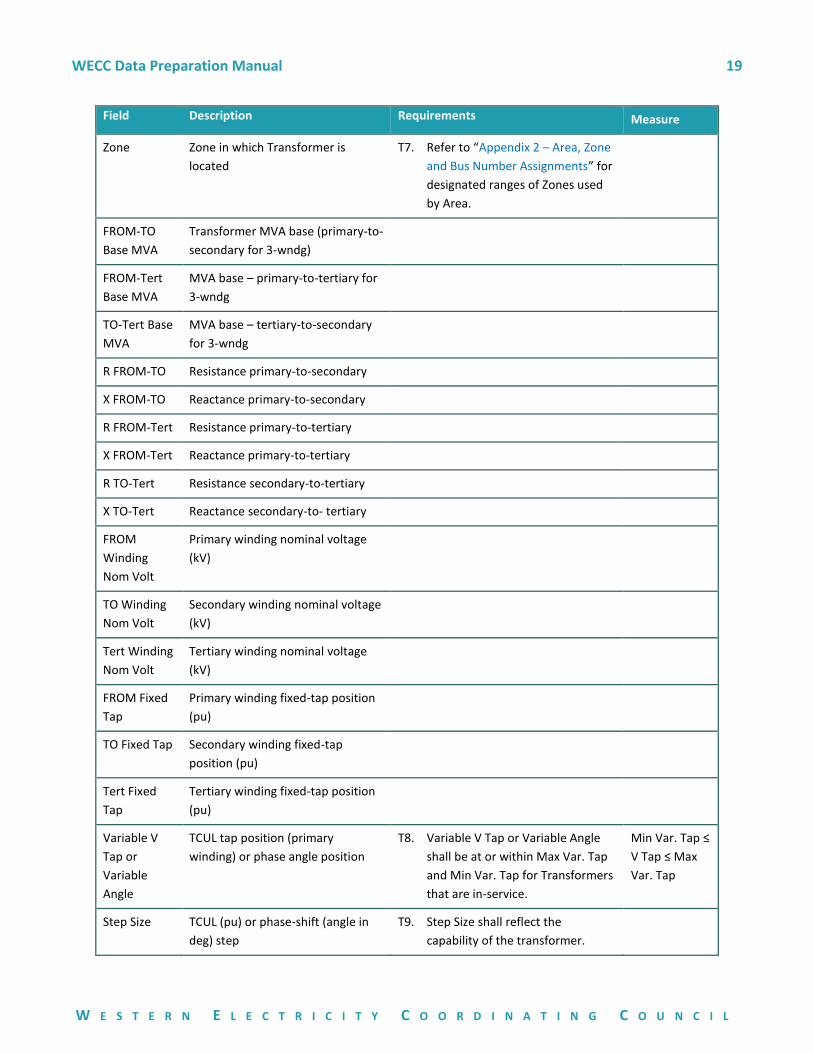
Field Description Requirements Measure
Zone Zone in which Transformer is
located
T7. Refer to “Appendix 2 – Area, Zone
and Bus Number Assignments” for
designated ranges of Zones used
by Area.
FROM-TO
Base MVA
Transformer MVA base (primary-to-
secondary for 3-wndg)
FROM-Tert
Base MVA
MVA base – primary-to-tertiary for
3-wndg
TO-Tert Base
MVA
MVA base – tertiary-to-secondary
for 3-wndg
R FROM-TO Resistance primary-to-secondary
X FROM-TO Reactance primary-to-secondary
R FROM-Tert Resistance primary-to-tertiary
X FROM-Tert Reactance primary-to-tertiary
R TO-Tert Resistance secondary-to-tertiary
X TO-Tert Reactance secondary-to- tertiary
FROM
Winding
Nom Volt
Primary winding nominal voltage
(kV)
TO Winding
Nom Volt
Secondary winding nominal voltage
(kV)
Tert Winding
Nom Volt
Tertiary winding nominal voltage
(kV)
FROM Fixed
Tap
Primary winding fixed-tap position
(pu)
TO Fixed Tap Secondary winding fixed-tap
position (pu)
Tert Fixed
Tap
Tertiary winding fixed-tap position
(pu)
Variable V
Tap or
Variable
Angle
TCUL tap position (primary
winding) or phase angle position
T8. Variable V Tap or Variable Angle
shall be at or within Max Var. Tap
and Min Var. Tap for Transformers
that are in-service.
Min Var. Tap ≤
V Tap ≤ Max
Var. Tap
Step Size TCUL (pu) or phase-shift (angle in
deg) step
T9. Step Size shall reflect the
capability of the transformer.
WECC Data Preparation Manual 20
W E S T E R N E L E C T R I C I T Y C O O R D I N A T I N G C O U N C I L
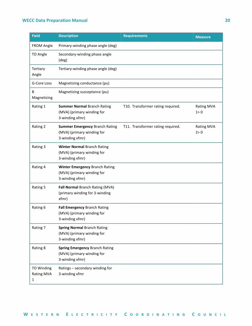
Field Description Requirements Measure
FROM Angle Primary-winding phase angle (deg)
TO Angle Secondary-winding phase angle
(deg)
Tertiary
Angle
Tertiary-winding phase angle (deg)
G-Core Loss Magnetizing conductance (pu)
B
Magnetizing
Magnetizing susceptance (pu)
Rating 1 Summer Normal Branch Rating
(MVA) (primary winding for
3-winding xfmr)
T10. Transformer rating required. Rating MVA
1> 0
Rating 2 Summer Emergency Branch Rating
(MVA) (primary winding for
3-winding xfmr)
T11. Transformer rating required. Rating MVA
2> 0
Rating 3 Winter Normal Branch Rating
(MVA) (primary winding for
3-winding xfmr)
Rating 4 Winter Emergency Branch Rating
(MVA) (primary winding for
3-winding xfmr)
Rating 5 Fall Normal Branch Rating (MVA)
(primary winding for 3-winding
xfmr)
Rating 6 Fall Emergency Branch Rating
(MVA) (primary winding for
3-winding xfmr)
Rating 7 Spring Normal Branch Rating
(MVA) (primary winding for
3-winding xfmr)
Rating 8 Spring Emergency Branch Rating
(MVA) (primary winding for
3-winding xfmr)
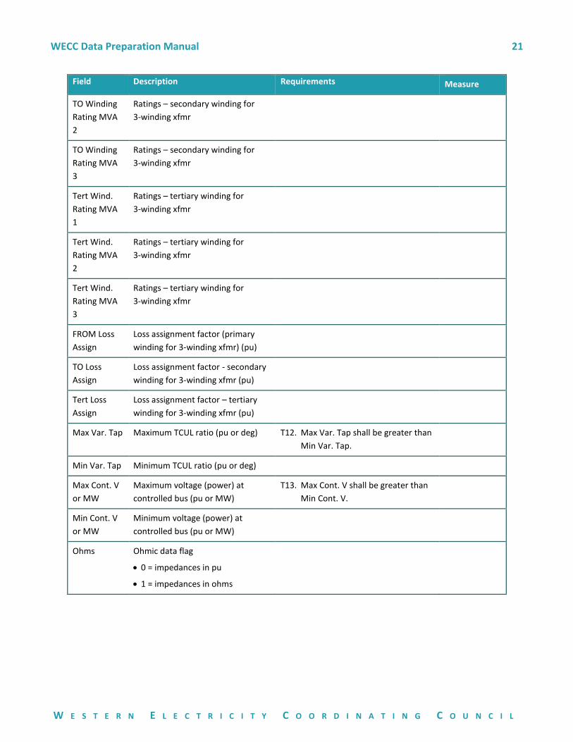
TO Winding
Rating MVA
1
Ratings – secondary winding for
3-winding xfmr
WECC Data Preparation Manual 21
W E S T E R N E L E C T R I C I T Y C O O R D I N A T I N G C O U N C I L
Field Description Requirements Measure
TO Winding
Rating MVA
2
Ratings – secondary winding for
3-winding xfmr
TO Winding
Rating MVA
3
Ratings – secondary winding for
3-winding xfmr
Tert Wind.
Rating MVA
1
Ratings – tertiary winding for
3-winding xfmr
Tert Wind.
Rating MVA
2
Ratings – tertiary winding for
3-winding xfmr
Tert Wind.
Rating MVA
3
Ratings – tertiary winding for
3-winding xfmr
FROM Loss
Assign
Loss assignment factor (primary
winding for 3-winding xfmr) (pu)
TO Loss
Assign
Loss assignment factor - secondary
winding for 3-winding xfmr (pu)
Tert Loss
Assign
Loss assignment factor – tertiary
winding for 3-winding xfmr (pu)
Max Var. Tap Maximum TCUL ratio (pu or deg) T12. Max Var. Tap shall be greater than
Min Var. Tap.
Min Var. Tap Minimum TCUL ratio (pu or deg)
Max Cont. V
or MW
Maximum voltage (power) at
controlled bus (pu or MW)
T13. Max Cont. V shall be greater than
Min Cont. V.
Min Cont. V
or MW
Minimum voltage (power) at
controlled bus (pu or MW)
Ohms Ohmic data flag
• 0 = impedances in pu
• 1 = impedances in ohms
WECC Data Preparation Manual 22
W E S T E R N E L E C T R I C I T Y C O O R D I N A T I N G C O U N C I L
Field Description Requirements Measure
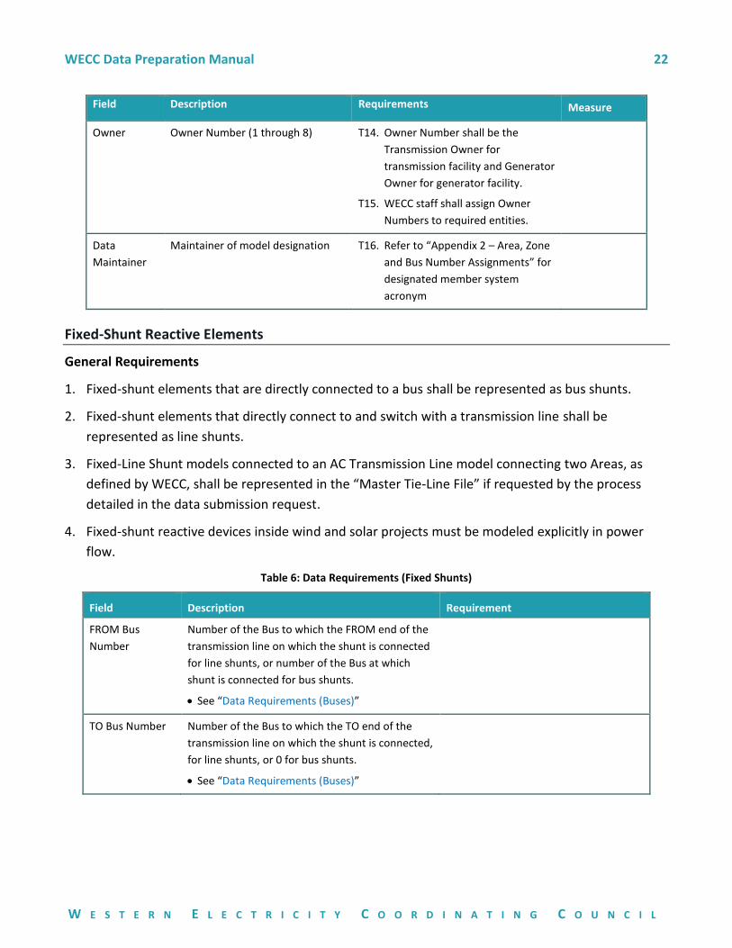
Owner Owner Number (1 through 8) T14. Owner Number shall be the
Transmission Owner for
transmission facility and Generator
Owner for generator facility.
T15. WECC staff shall assign Owner
Numbers to required entities.
Data
Maintainer
Maintainer of model designation T16. Refer to “Appendix 2 – Area, Zone
and Bus Number Assignments” for
designated member system
acronym
Fixed-Shunt Reactive Elements
General Requirements
1. Fixed-shunt elements that are directly connected to a bus shall be represented as bus shunts.
2. Fixed-shunt elements that directly connect to and switch with a transmission line shall be
represented as line shunts.
3. Fixed-Line Shunt models connected to an AC Transmission Line model connecting two Areas, as
defined by WECC, shall be represented in the “Master Tie-Line File” if requested by the process
detailed in the data submission request.
4. Fixed-shunt reactive devices inside wind and solar projects must be modeled explicitly in power
flow.
Table 6: Data Requirements (Fixed Shunts)
Field Description Requirement
FROM Bus
Number
Number of the Bus to which the FROM end of the
transmission line on which the shunt is connected
for line shunts, or number of the Bus at which
shunt is connected for bus shunts.
• See “Data Requirements (Buses)”
TO Bus Number Number of the Bus to which the TO end of the
transmission line on which the shunt is connected,
for line shunts, or 0 for bus shunts.
• See “Data Requirements (Buses)”
WECC Data Preparation Manual 23
W E S T E R N E L E C T R I C I T Y C O O R D I N A T I N G C O U N C I L
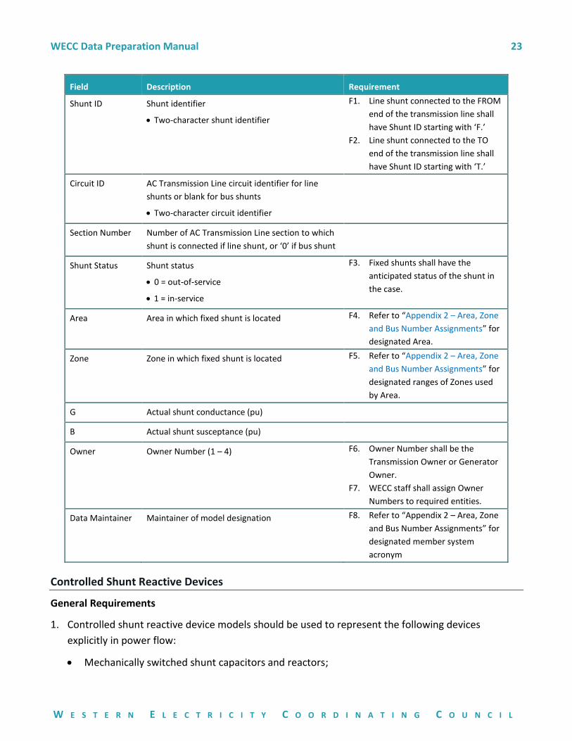
Field Description Requirement
Shunt ID Shunt identifier
• Two-character shunt identifier
F1. Line shunt connected to the FROM
end of the transmission line shall
have Shunt ID starting with ‘F.’
F2. Line shunt connected to the TO
end of the transmission line shall
have Shunt ID starting with ‘T.’
Circuit ID AC Transmission Line circuit identifier for line
shunts or blank for bus shunts
• Two-character circuit identifier
Section Number Number of AC Transmission Line section to which
shunt is connected if line shunt, or ‘0’ if bus shunt
Shunt Status Shunt status
• 0 = out-of-service
• 1 = in-service
F3. Fixed shunts shall have the
anticipated status of the shunt in
the case.
Area Area in which fixed shunt is located F4. Refer to “Appendix 2 – Area, Zone
and Bus Number Assignments” for
designated Area.
Zone Zone in which fixed shunt is located F5. Refer to “Appendix 2 – Area, Zone
and Bus Number Assignments” for
designated ranges of Zones used
by Area.
G Actual shunt conductance (pu)
B Actual shunt susceptance (pu)
Owner Owner Number (1 – 4) F6. Owner Number shall be the
Transmission Owner or Generator
Owner.
F7. WECC staff shall assign Owner
Numbers to required entities.
Data Maintainer Maintainer of model designation F8. Refer to “Appendix 2 – Area, Zone
and Bus Number Assignments” for
designated member system
acronym
Controlled Shunt Reactive Devices
General Requirements
1. Controlled shunt reactive device models should be used to represent the following devices
explicitly in power flow:
• Mechanically switched shunt capacitors and reactors;
WECC Data Preparation Manual 24
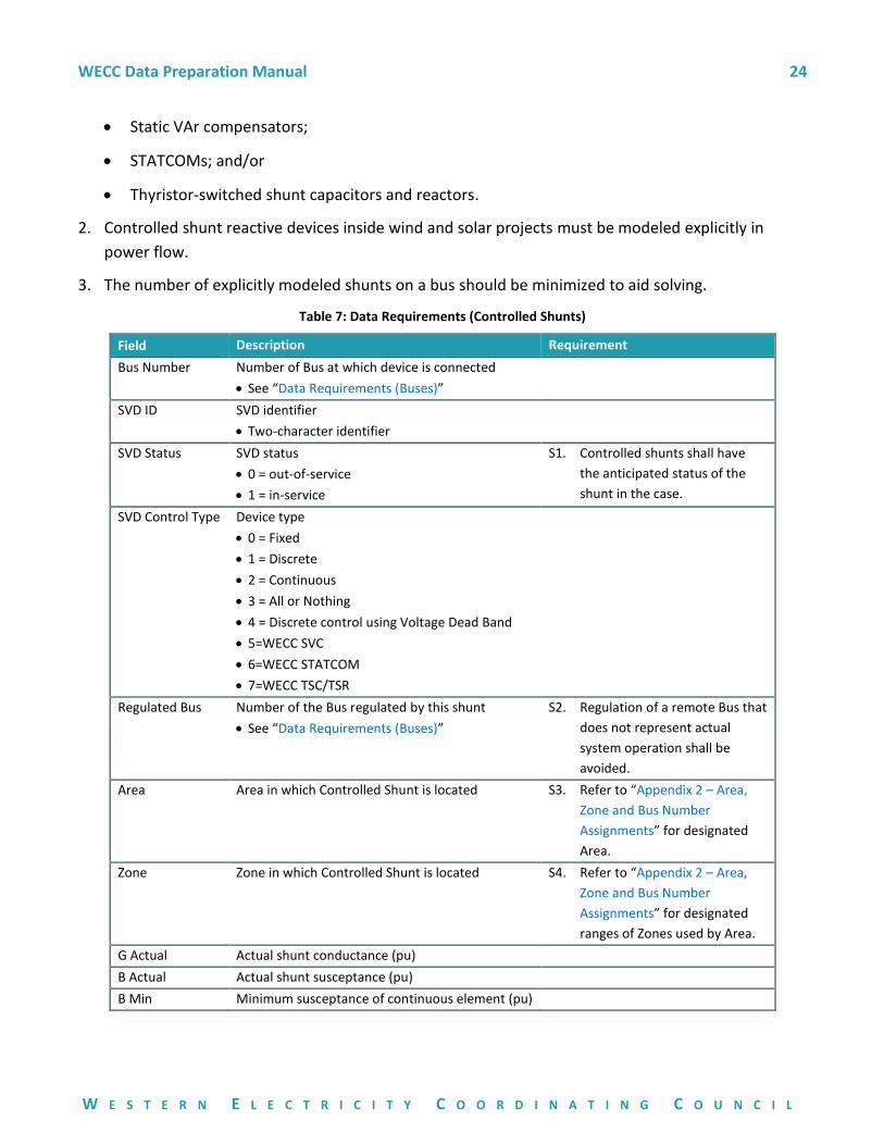
W E S T E R N E L E C T R I C I T Y C O O R D I N A T I N G C O U N C I L
• Static VAr compensators;
• STATCOMs; and/or
• Thyristor-switched shunt capacitors and reactors.
2. Controlled shunt reactive devices inside wind and solar projects must be modeled explicitly in
power flow.
3. The number of explicitly modeled shunts on a bus should be minimized to aid solving.
Table 7: Data Requirements (Controlled Shunts)
Field Description Requirement
Bus Number Number of Bus at which device is connected
• See “Data Requirements (Buses)”
SVD ID SVD identifier
• Two-character identifier
SVD Status SVD status
• 0 = out-of-service
• 1 = in-service
S1. Controlled shunts shall have
the anticipated status of the
shunt in the case.
SVD Control Type Device type
• 0 = Fixed
• 1 = Discrete
• 2 = Continuous
• 3 = All or Nothing
• 4 = Discrete control using Voltage Dead Band
• 5=WECC SVC
• 6=WECC STATCOM
• 7=WECC TSC/TSR
Regulated Bus Number of the Bus regulated by this shunt
• See “Data Requirements (Buses)”
S2. Regulation of a remote Bus that
does not represent actual
system operation shall be
avoided.
Area Area in which Controlled Shunt is located S3. Refer to “Appendix 2 – Area,
Zone and Bus Number
Assignments” for designated
Area.
Zone Zone in which Controlled Shunt is located S4. Refer to “Appendix 2 – Area,
Zone and Bus Number
Assignments” for designated
ranges of Zones used by Area.
G Actual Actual shunt conductance (pu)
B Actual Actual shunt susceptance (pu)
B Min Minimum susceptance of continuous element (pu)
WECC Data Preparation Manual 25
W E S T E R N E L E C T R I C I T Y C O O R D I N A T I N G C O U N C I L
Field Description Requirement
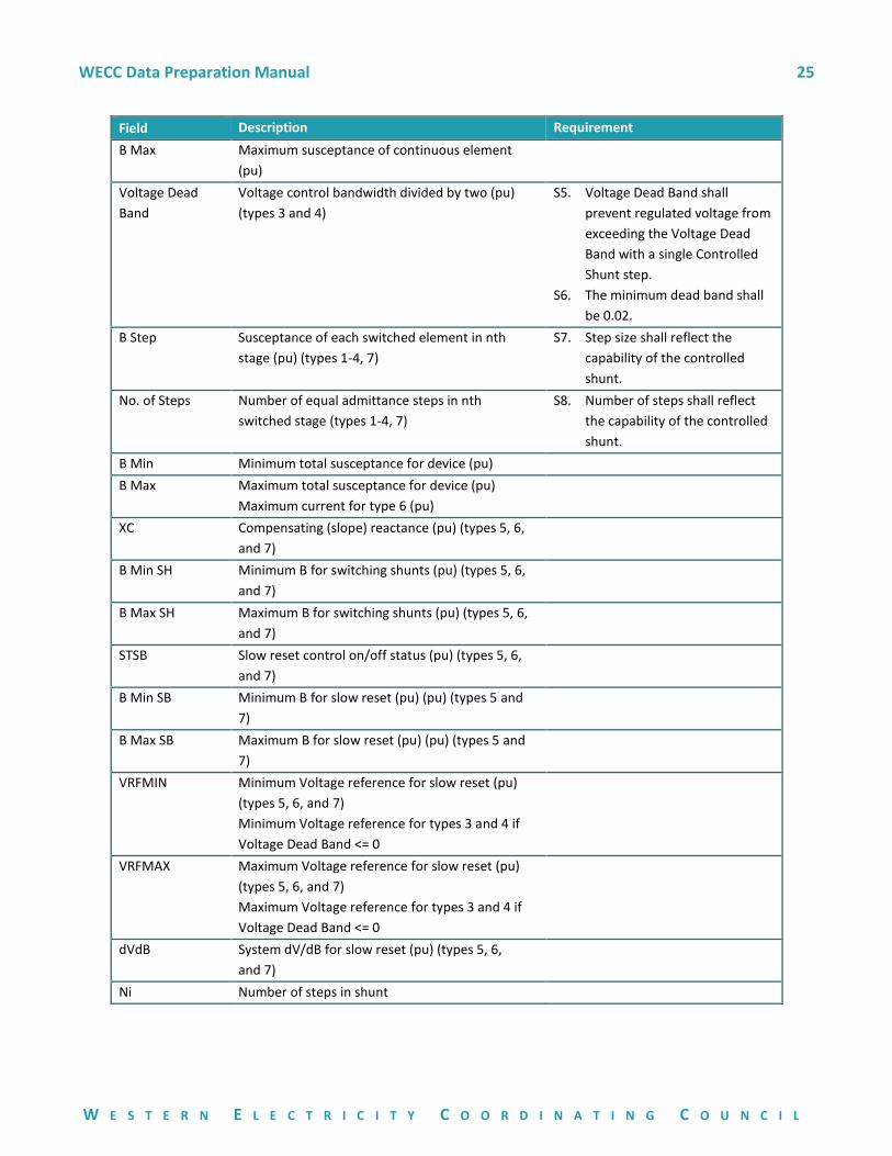
B Max Maximum susceptance of continuous element
(pu)
Voltage Dead
Band
Voltage control bandwidth divided by two (pu)
(types 3 and 4)
S5. Voltage Dead Band shall
prevent regulated voltage from
exceeding the Voltage Dead
Band with a single Controlled
Shunt step.
S6. The minimum dead band shall
be 0.02.
B Step Susceptance of each switched element in nth
stage (pu) (types 1-4, 7)
S7. Step size shall reflect the
capability of the controlled
shunt.
No. of Steps Number of equal admittance steps in nth
switched stage (types 1-4, 7)
S8. Number of steps shall reflect
the capability of the controlled
shunt.
B Min Minimum total susceptance for device (pu)
B Max Maximum total susceptance for device (pu)
Maximum current for type 6 (pu)
XC Compensating (slope) reactance (pu) (types 5, 6,
and 7)
B Min SH Minimum B for switching shunts (pu) (types 5, 6,
and 7)
B Max SH Maximum B for switching shunts (pu) (types 5, 6,
and 7)
STSB Slow reset control on/off status (pu) (types 5, 6,
and 7)
B Min SB Minimum B for slow reset (pu) (pu) (types 5 and
7)
B Max SB Maximum B for slow reset (pu) (pu) (types 5 and
7)
VRFMIN Minimum Voltage reference for slow reset (pu)
(types 5, 6, and 7)
Minimum Voltage reference for types 3 and 4 if
Voltage Dead Band <= 0
VRFMAX Maximum Voltage reference for slow reset (pu)
(types 5, 6, and 7)
Maximum Voltage reference for types 3 and 4 if
Voltage Dead Band <= 0
dVdB System dV/dB for slow reset (pu) (types 5, 6,
and 7)
Ni Number of steps in shunt
WECC Data Preparation Manual 26
W E S T E R N E L E C T R I C I T Y C O O R D I N A T I N G C O U N C I L
Field Description Requirement
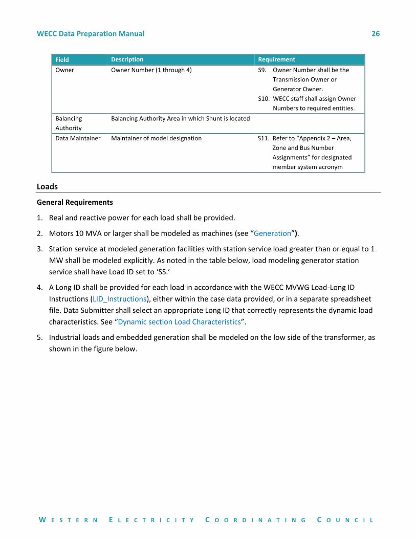
Owner Owner Number (1 through 4) S9. Owner Number shall be the
Transmission Owner or
Generator Owner.
S10. WECC staff shall assign Owner
Numbers to required entities.
Balancing
Authority
Balancing Authority Area in which Shunt is located
Data Maintainer Maintainer of model designation S11. Refer to “Appendix 2 – Area,
Zone and Bus Number
Assignments” for designated
member system acronym
Loads
General Requirements
1. Real and reactive power for each load shall be provided.
2. Motors 10 MVA or larger shall be modeled as machines (see “Generation”).
3. Station service at modeled generation facilities with station service load greater than or equal to 1
MW shall be modeled explicitly. As noted in the table below, load modeling generator station
service shall have Load ID set to ‘SS.’
4. A Long ID shall be provided for each load in accordance with the WECC MVWG Load-Long ID
Instructions (LID_Instructions), either within the case data provided, or in a separate spreadsheet
file. Data Submitter shall select an appropriate Long ID that correctly represents the dynamic load
characteristics. See “Dynamic section Load Characteristics”.
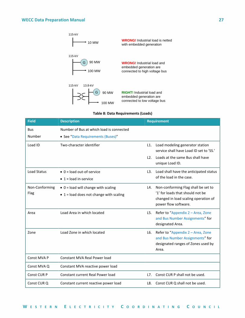
5. Industrial loads and embedded generation shall be modeled on the low side of the transformer, as
shown in the figure below.
WECC Data Preparation Manual 27
W E S T E R N E L E C T R I C I T Y C O O R D I N A T I N G C O U N C I L
Table 8: Data Requirements (Loads)
Field Description Requirement
Bus
Number
Number of Bus at which load is connected
• See “Data Requirements (Buses)”
Load ID Two-character identifier L1. Load modeling generator station
service shall have Load ID set to ‘SS.’
L2. Loads at the same Bus shall have
unique Load ID.
Load Status • 0 = load out-of-service
• 1 = load in-service
L3. Load shall have the anticipated status
of the load in the case.
Non-Conforming
Flag
• 0 = load will change with scaling
• 1 = load does not change with scaling
L4. Non-conforming Flag shall be set to
‘1’ for loads that should not be
changed in load scaling operation of
power flow software.
Area Load Area in which located L5. Refer to “Appendix 2 – Area, Zone
and Bus Number Assignments” for
designated Area.
Zone Load Zone in which located L6. Refer to “Appendix 2 – Area, Zone
and Bus Number Assignments” for
designated ranges of Zones used by
Area.
Const MVA P Constant MVA Real Power load
Const MVA Q Constant MVA reactive power load
Const CUR P Constant current Real Power load L7. Const CUR P shall not be used.
Const CUR Q Constant current reactive power load L8. Const CUR Q shall not be used.
10 MW
115-kV
WRONG! Industrial load is netted
with embedded generation
100 MW
115-kV
WRONG! Industrial load and
embedded generation are
connected to high voltage bus
G 90 MW
100 MW
115-kV
RIGHT! Industrial load and
embedded generation are
connected to low voltage bus
G 90 MW
13.8-kV
WECC Data Preparation Manual 28
W E S T E R N E L E C T R I C I T Y C O O R D I N A T I N G C O U N C I L
Field Description Requirement
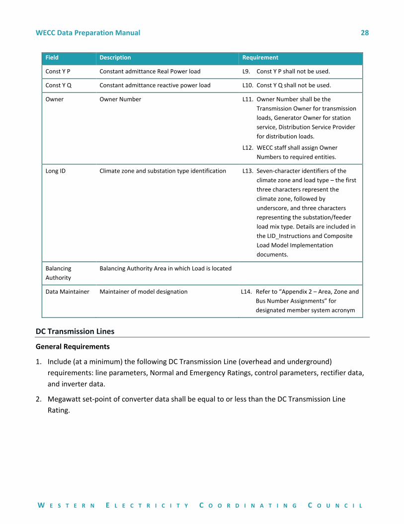
Const Y P Constant admittance Real Power load L9. Const Y P shall not be used.
Const Y Q Constant admittance reactive power load L10. Const Y Q shall not be used.
Owner Owner Number L11. Owner Number shall be the
Transmission Owner for transmission
loads, Generator Owner for station
service, Distribution Service Provider
for distribution loads.
L12. WECC staff shall assign Owner
Numbers to required entities.
Long ID Climate zone and substation type identification L13. Seven-character identifiers of the
climate zone and load type – the first
three characters represent the
climate zone, followed by
underscore, and three characters
representing the substation/feeder
load mix type. Details are included in
the LID_Instructions and Composite
Load Model Implementation
documents.
Balancing
Authority
Balancing Authority Area in which Load is located
Data Maintainer Maintainer of model designation L14. Refer to “Appendix 2 – Area, Zone and
Bus Number Assignments” for
designated member system acronym
DC Transmission Lines
General Requirements
1. Include (at a minimum) the following DC Transmission Line (overhead and underground)
requirements: line parameters, Normal and Emergency Ratings, control parameters, rectifier data,
and inverter data.
2. Megawatt set-point of converter data shall be equal to or less than the DC Transmission Line
Rating.
WECC Data Preparation Manual 29
W E S T E R N E L E C T R I C I T Y C O O R D I N A T I N G C O U N C I L
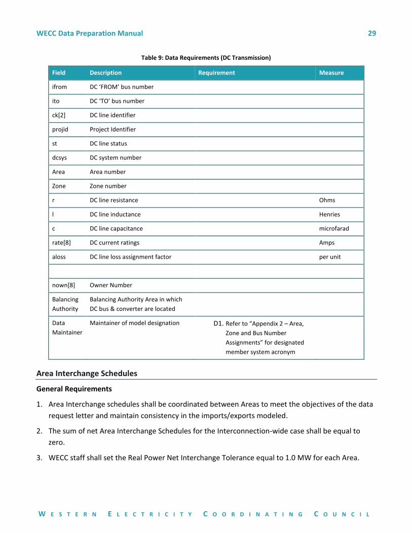
Table 9: Data Requirements (DC Transmission)
Field Description Requirement Measure
ifrom DC ‘FROM’ bus number
ito DC ‘TO’ bus number
ck[2] DC line identifier
projid Project Identifier
st DC line status
dcsys DC system number
Area Area number
Zone Zone number
r DC line resistance Ohms
l DC line inductance Henries
c DC line capacitance microfarad
rate[8] DC current ratings Amps
aloss DC line loss assignment factor per unit
nown[8] Owner Number
Balancing
Authority
Balancing Authority Area in which
DC bus & converter are located
Data
Maintainer
Maintainer of model designation D1. Refer to “Appendix 2 – Area,
Zone and Bus Number
Assignments” for designated
member system acronym
Area Interchange Schedules
General Requirements
1. Area Interchange schedules shall be coordinated between Areas to meet the objectives of the data
request letter and maintain consistency in the imports/exports modeled.
2. The sum of net Area Interchange Schedules for the Interconnection-wide case shall be equal to
zero.
3. WECC staff shall set the Real Power Net Interchange Tolerance equal to 1.0 MW for each Area.
WECC Data Preparation Manual 30
W E S T E R N E L E C T R I C I T Y C O O R D I N A T I N G C O U N C I L
Master Tie-Line File
When requested by the process detailed in the data submission request the Master Tie-Line File
(MTLF) contains:
• Master lists of Owners, Balancing Authority Areas and Zones;
• Path definitions and ratings for paths in the WECC Path Rating Catalog;
• Lists of lines and transformers that interconnect Areas; and
• Placeholder for Area-to-Area transactions for the existing system.
General Requirements Used to Build Interconnection-Wide Cases
1. WECC staff shall maintain the MTLF.
2. WECC staff shall post the current MTLF in the present year’s base-case files on the WECC website.
3. The MTLF is used in the compilation of all base cases to ensure consistency of steady-state data
common to multiple Areas.
4. Updates to the MTLF shall be coordinated between Areas and submitted to WECC staff in an EPC
file format or excel spreadsheet format as necessary by the Data Submitter.
5. The MTLF shall be maintained and applied to all WECC base cases. The tie-line data pertaining to
planning horizon cases will be handled on a case-by-case basis.
Data Requirements (Area Interchange)
1. Tie-Lines –Existing transmission lines (including line shunts) and transformers connecting two Areas
shall have steady-state data submitted to WECC staff for inclusion in the MTLF (see Section “AC
Transmission Lines” and “Transformers” respectively). Tie changes are not captured when only
included in the case data submissions. These changes or updates must be submitted separately
from typical case data submissions (or as separate files included within the case data).
2. Zones – Zone Names and Zone Numbers shall be maintained in the MTLF in accordance to the
process detailed in the data submission request. Zone assignments to the WECC member systems
can be found in Appendix 2 (see “Appendix 2 – Area, Zone and Bus Number Assignments.”)
3. WECC staff shall identify paths (as listed in the WECC Path Rating Catalog) in accordance to the
process detailed in the data submission request. The Interface Number shall match the WECC path
number. Rating 1 shall be used for the Path Transfer Limit for prevailing flow direction and Rating 2
shall be used for the secondary flow direction Path Transfer Limit.
4. WECC path element information shall be maintained in the MTLF in accordance to the process
detailed in the data submission request. Data Submitters shall provide updates to WECC staff as
changes are made or as facilities are placed in-service.
WECC Data Preparation Manual 31
W E S T E R N E L E C T R I C I T Y C O O R D I N A T I N G C O U N C I L
5. Facility owners of DC buses, lines, and converters that are part of any Area tie-line shall provide the
steady-state data to be maintained in the MTLF. (see Section “DC Transmission Lines”).
6. Transformer Impedance Correction Table – Impedance correction parameters to be used for TCUL
transformers and phase-shifting transformers shall be maintained in the MTLF in accordance to the
process detailed in the data submission request.
7. Owner Data – A list of Owner Numbers, names, and four-character abbreviations shall be
maintained in the MTLF in accordance to the process detailed in the data submission request.
8. Transaction Data – There must be a transaction for any ties between Areas. WECC Staff manages
this data in accordance to the process detailed in the data submission request on a case-by-case
basis.
9. Balancing Authority – WECC staff will maintain a list of Balancing Authority Areas (BAA) used in the
existing operation of the transmission system.
AC Substations
General Requirements:
1. Substations represent all the buses in a substation. These collections of buses are connected by
transformer, bus sectionalizing breakers, switches and/or short transmission lines.
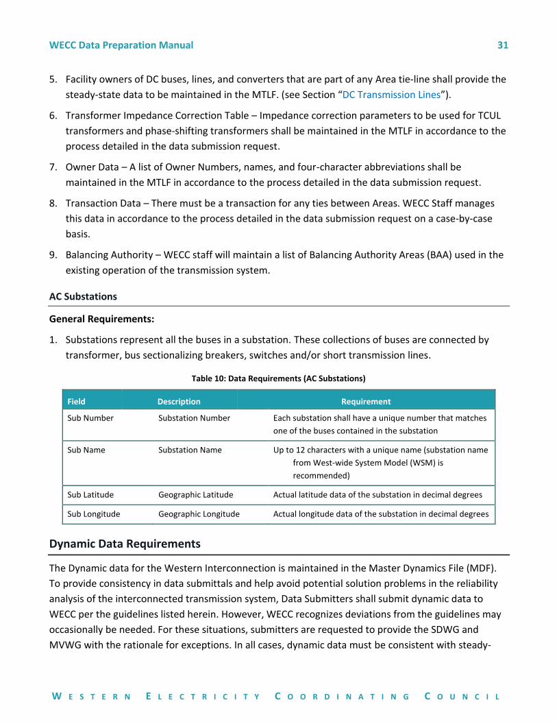
Table 10: Data Requirements (AC Substations)
Field Description Requirement
Sub Number Substation Number Each substation shall have a unique number that matches
one of the buses contained in the substation
Sub Name Substation Name Up to 12 characters with a unique name (substation name
from West-wide System Model (WSM) is
recommended)
Sub Latitude Geographic Latitude Actual latitude data of the substation in decimal degrees
Sub Longitude Geographic Longitude Actual longitude data of the substation in decimal degrees
Dynamic Data Requirements
The Dynamic data for the Western Interconnection is maintained in the Master Dynamics File (MDF).
To provide consistency in data submittals and help avoid potential solution problems in the reliability
analysis of the interconnected transmission system, Data Submitters shall submit dynamic data to
WECC per the guidelines listed herein. However, WECC recognizes deviations from the guidelines may
occasionally be needed. For these situations, submitters are requested to provide the SDWG and
MVWG with the rationale for exceptions. In all cases, dynamic data must be consistent with steady-
WECC Data Preparation Manual 32
W E S T E R N E L E C T R I C I T Y C O O R D I N A T I N G C O U N C I L
state data provided for each WECC Base Case. Data Submitters are responsible for providing data for
facilities in the WECC-approved format.
Dynamic data is submitted as soon as any new data becomes available. Dynamic data may become
available outside the scheduled case building process due to individual entity equipment testing
programs, such as the generator testing program.
Dynamic data for new generators and updates for existing generators are submitted via the WECC
Generating Unit Model Validation Policy. This Policy includes the roles and responsibilities of the
Generator Owner, the Transmission Planner, and WECC.
Approved dynamic models conform to the WECC Dynamic Modeling Procedure. All dynamic models
contained in the MDF shall be those approved by the MVWG. If the model you want to use is not on
the approved list, you must go through the MVWG and follow the WECC Dynamic Modeling Procedure.
The following approach to dynamic data shall apply Interconnection-wide:
• Generators and other dynamic devices shall be represented with approved dynamic data as
recommended by the MVWG to represent the designated dynamic equipment modeled in
WECC Base Cases. The approved models can be found within the Approved Dynamic Model
Library
• When new models have been added to or obsolete models have been removed from the
Approved Dynamic Model Library, Data Subcommittee and SDWG will determine an
appropriate implementation schedule and scope for submitting the necessary data required by
the newly approved models.
• Estimated or typical manufacturer’s dynamic data based on facilities of similar design and
characteristics may be used to represent planned generators and other dynamic devices if
specific design data cannot be obtained. MVWG maintains the Typical Machine Data document.
Specific dynamic design data shall be submitted per the WECC Steady-State and Dynamic Data
Criterion. See “General Data Requirements and Reporting Procedures.”
• Where there is a difference between the requirements of this document and the WECC
Generating Unit Model Validation Policy, the WECC Generating Unit Model Validation Policy
shall preside.
• Typical dynamics studies are up to 60 seconds from the initiating event. All models, on the
Approved Dynamic Model Library list that can respond within that time frame, shall be
submitted.
WECC Data Preparation Manual 33
W E S T E R N E L E C T R I C I T Y C O O R D I N A T I N G C O U N C I L
Generation Requirements
1. Dynamic data for generators, synchronous condensers, excitation systems, voltage regulators,
turbine governor systems, power system stabilizers, and other associated generation equipment
shall be derived from test results obtained by adhering to the WECC Generating Unit Model
Validation Policy for each unit represented in WECC Base Cases according to thresholds as specified
in Section IV. This includes, as appropriate to the model, items such as inertia constant, damping
coefficient, saturation parameters, and direct and quadrature axis reactances and time constants.
2. Generator Owners shall submit power plant data in accordance to the voltage and MVA size
thresholds for aggregating generator models described in the Section IV. (see Section
“Generation”)
3. Netting of planned generators represented in WECC Base Cases shall conform to the threshold
requirements of the Section IV.
4. The MWCAP parameter in the dynamic turbine-governor model shall be greater than or equal to
the Pmax parameter of the generator steady-state model to avoid governor initialization problems.
5. Power System Stabilizer (PSS) Dynamic data shall be submitted for all generators that have active
PSS. See the WECC Policy Statement on Power System Stabilizers document.
6. Existing generators shall follow the WECC Generator Unit Model Validation Policy.
7. User defined models for collector based generator (Wind and Solar plants) representation shall be
avoided.
Load Requirements
Model voltage and frequency characteristics explicitly for each individual load if possible. However, use
the Composite Load Model for loads when frequency and voltage characteristics are not explicitly
known. The goal of this section is to model effects of voltage and frequency on load as accurately as
possible.
1. A composite load model shall exist for each load modeled in the steady-state data.
2. Keep dynamic load data characteristics consistent with reported steady-state data.
3. For loads less than 5 MW, Data Submitters will work with WECC staff to establish a default load
representation record for each Area to represent loads not modeled with the Composite Load
Model. This is to avoid the load representation defaulting to constant power (PSLF default). If
actual dynamic load characteristics are not available, load should be modeled as constant current
P, and constant impedance Q. Bus specific exceptions to the default load representation must be
submitted to WECC staff for inclusion in the MDF.
WECC Data Preparation Manual 34
W E S T E R N E L E C T R I C I T Y C O O R D I N A T I N G C O U N C I L
Underfrequency Load Shedding (UFLS)
1. Include UFLS records for all loads that have UFLS relays on the interconnected system.
2. The pickup frequency of each stage shall be lower than that of the previous stage. UFLS must
comply with WECC-coordinated off-nominal requirements as specified in the WECC Off-Nominal
Frequency Load-Shedding Plan document.
3. Pertinent load data must be included in the MDF. All UFLS data in the MDF must match bus, load,
and/or branch identifiers in the cases.
4. The UFLS models must correspond to UFLS information provided to the WECC Underfrequency
Load-Shedding Review Group in accordance with WECC Underfrequency Load-Shedding Criterion.
5. To include data in Planning cases, submit the data with the case development and identify as
planning data.
Undervoltage Load Shedding (UVLS)
1. UVLS records must be included for all loads that have under-voltage relays on the interconnected
system.
2. The pick-up and time-delay settings must be coordinated for each stage with the previous stage.
3. Pertinent load data must be included in the MDF. All UVLS data in the MDF must match bus, load,
and/or branch identifiers in the cases.
Relays
Relay models as approved for use by the SDWG must be included per the time line and scope it
establishes for primary relays. Data submitters are also strongly encouraged to submit all relevant
backup relay modeling data.
Back-to-Back DC Ties
Netting is allowed for back-to-back DC ties. Back-to-back DC ties shall be represented as generation in
the power flow, but netted in dynamic data. The record should include an ID designation of ‘DC’ on
the generator record.
DC Lines, SVC and D-VAr systems
1. Device-specific dynamic data for dynamic devices shall be modeled, including but not limited to,
static VAr compensators and controllers, high-voltage direct-current systems, flexible AC
transmission systems, and automatically switched shunt and series capacitors or reactors.
2. DC lines and SVC systems shall be modeled, to the maximum extent possible, to accurately reflect
actual system performance.
WECC Data Preparation Manual 35
W E S T E R N E L E C T R I C I T Y C O O R D I N A T I N G C O U N C I L
3. DC bus numbering must be coordinated with WECC staff prior to model submission.
Remedial Action Scheme and Associated Contingency Data
Remedial Action Scheme (RAS) and associated Contingency data shall be shared with WECC and WECC
shall securely store the information separate from the Interconnection-wide cases.
The following approach should be taken when providing contingency and RAS data:
• All models should be provided upon request by Data Submitters in their preferred format until
the WECC common format is available in the providers preferred software.
• RAS models should be provided if the affected elements are modeled in the case.
• All models should identify the data owner by naming the models with the member system
acronym and an underscore at the front. (i.e ‘member system acronym’ ‘ descriptive model
name’)
• RAS and associated contingency models shall be provided for all operations base cases. These are
denoted by an “-OP” in the base case compilation schedule. New models shall be provided when
the RAS are placed in use by the Operations department of each member, while existing models
need only be updated when changes occur. Data Submitters shall notify WECC staff if any already
provided models are no longer online and should be removed.
• RAS data will be made available on the WECC website. It will only be accessible to those users who
are logged in and authorized to access it.
WECC Data Preparation Manual 36
W E S T E R N E L E C T R I C I T Y C O O R D I N A T I N G C O U N C I L
Disclaimer
WECC receives data used in its analyses from a wide variety of sources. WECC strives to source its data
from reliable entities and undertakes reasonable efforts to validate the accuracy of the data used.
WECC believes the data contained herein and used in its analyses is accurate and reliable. However,
WECC disclaims any and all representations, guarantees, warranties, and liability for the information
contained herein and any use thereof. Persons who use and rely on the information contained herein
do so at their own risk.
WECC Data Preparation Manual
W E S T E R N E L E C T R I C I T Y C O O R D I N A T I N G C O U N C I L
Appendix 1 – Late Data Procedure
The objective of the Late Data Procedure is to preserve the original schedule for the development of
base cases in accordance with each year's Base Case Compilation Schedule, and the Case Description
sheet in the data request letter for each case. The Late Data Procedure describes Data Submitter and
staff data submittal responsibilities as well as actions to be taken for actual delays or anticipated delays
in the submittal of data, or for the submittal of unusable data. This procedure does not take effect until
one of the following occurs:
• A data submittal date has been missed; or
• There is sufficient reason to believe that a submittal date will be missed; or
• It is determined that the submitted data is not usable.
Success of the case development program depends on timely and accurate data submittal, review, and
support of the development of each base case. A Data Submitter not meeting a scheduled response
date listed in the Base Case Compilation Schedule with a usable response could result in a delay in the
case development schedule if left uncorrected.
Examples of unusable data:
• Data from two neighboring Data Submitters with inter-area schedules that do not match; and
• Data with such significant problems that it cannot be used for the comment phase of the
development process which; therefore, delays the progress of the case development.
Any unusable data received by WECC staff must be corrected by the Data Submitter to not further
impair the schedule or it will be rectified in accordance with this Late Data Procedure, as will any late
data or anticipated late data.
Data Submitter and Staff Responsibilities
It is the responsibility of the Data Submitters to submit timely and accurate data in accordance with
the Base Case Compilation Schedule and the Case Description sheet in the data request letter. A
schedule can be impaired either by data being submitted after the scheduled due date or by the
submission of unusable data, even if it is submitted on time.
If, in the judgment of WECC staff, it appears that the schedule will be impaired due to lack of usable
data response by the Data Submitters, it will be the responsibility of WECC staff to provide the data for
the case in question.
WECC Data Preparation Manual 38
W E S T E R N E L E C T R I C I T Y C O O R D I N A T I N G C O U N C I L
Actions to Take
There are two actions specified by this procedure in the event the WECC staff must exercise its late
data responsibilities for a delinquent entity. The first is the action of assuming the responsibility for
submitting the data and the second is the notification of such action. If the staff takes over the
responsibility for the submittal of data for the delinquent entity, the data to be submitted should
always be the best data available in the judgment of the person submitting the data. The data should
be submitted in such a way that the original schedule is maintained or not further impaired.
When WECC staff takes over data submittal responsibility for a Data Submitter:
1. WECC staff will notify the Data Submitter and copy the notification of the action taken to:
a. RAC and Data Subcommittee representatives of the Data Submitter; and
b. SDWG.
2. When the case involved is an operating case, the staff will send a notification letter to:
a. The Operating Committee (OC) and the Operating Transfer Capability Policy Group Study
Group (OTCPGSG).
The notification will consist of the nature and extent of the action taken, and reasons. Those who
consistently abuse the base-case development process by submitting late or unusable data may be
significantly compromising the reliability of the Western Interconnection transmission system.
Backfitting of Late Data
The Late Data Procedure allows for the WECC staff to take over data submittal responsibilities for a
Data Submitter in the event that entity is unable to submit usable data in accordance with the defined
schedule. If the Data Submitter’s data should subsequently become available, the data shall be
submitted to the WECC staff to partially or fully replace that which was previously submitted.
However, the staff may refuse to accept this backfit data if, in its judgment, the backfit data is no
better than the data already in the case or if there would be unacceptable impairment of the schedule
by accepting the backfit data.
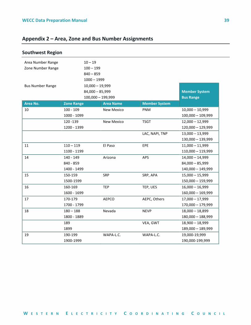
WECC Data Preparation Manual 39
W E S T E R N E L E C T R I C I T Y C O O R D I N A T I N G C O U N C I L
Appendix 2 – Area, Zone and Bus Number Assignments
Southwest Region
Area Number Range 10 – 19
Zone Number Range 100 – 199
840 – 859
1000 – 1999
Bus Number Range 10,000 – 19,999
84,000 – 85,999
100,000 – 199,999
Member System
Bus Range
Area No. Zone Range Area Name Member System
10 100 - 109
1000 - 1099
New Mexico PNM 10,000 – 10,999
100,000 – 109,999
120 -139
1200 - 1399
New Mexico TSGT 12,000 – 12,999
120,000 – 129,999
LAC, NAPI, TNP 13,000 – 13,999
130,000 – 139,999
11 110 – 119
1100 - 1199
El Paso EPE 11,000 – 11,999
110,000 – 119,999
14 140 - 149
840 - 859
1400 - 1499
Arizona APS 14,000 – 14,999
84,000 – 85,999
140,000 – 149,999
15 150-159
1500-1599
SRP SRP, APA 15,000 – 15,999
150,000 – 159,999
16 160-169
1600 - 1699
TEP TEP, UES 16,000 – 16,999
160,000 – 169,999
17 170-179
1700 - 1799
AEPCO AEPC, Others 17,000 – 17,999
170,000 – 179,999
18 180 – 188
1800 - 1889
Nevada NEVP 18,000 – 18,899
180,000 – 188,999
189
1899
VEA, GWT 18,900 – 18,999
189,000 – 189,999
19 190-199
1900-1999
WAPA-L.C. WAPA-L.C. 19,000-19,999
190,000-199,999
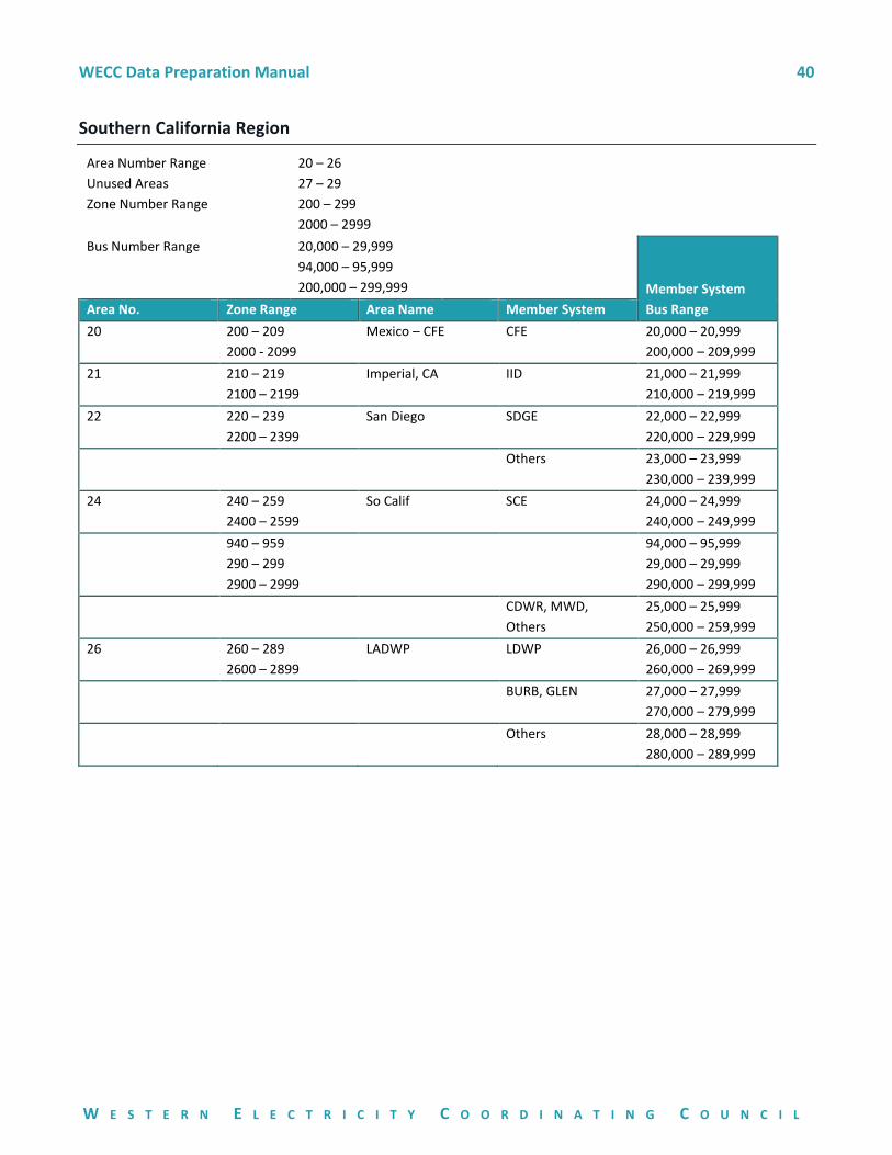
WECC Data Preparation Manual 40
W E S T E R N E L E C T R I C I T Y C O O R D I N A T I N G C O U N C I L
Southern California Region
Area Number Range 20 – 26
Unused Areas 27 – 29
Zone Number Range 200 – 299
2000 – 2999
Bus Number Range 20,000 – 29,999
94,000 – 95,999
200,000 – 299,999
Member System
Bus Range Area No. Zone Range Area Name Member System
20 200 – 209
2000 - 2099
Mexico – CFE CFE 20,000 – 20,999
200,000 – 209,999
21 210 – 219
2100 – 2199
Imperial, CA IID 21,000 – 21,999
210,000 – 219,999
22 220 – 239
2200 – 2399
San Diego SDGE 22,000 – 22,999
220,000 – 229,999
Others 23,000 – 23,999
230,000 – 239,999
24 240 – 259
2400 – 2599
So Calif SCE 24,000 – 24,999
240,000 – 249,999
940 – 959
290 – 299
2900 – 2999
94,000 – 95,999
29,000 – 29,999
290,000 – 299,999
CDWR, MWD,
Others
25,000 – 25,999
250,000 – 259,999
26 260 – 289
2600 – 2899
LADWP LDWP 26,000 – 26,999
260,000 – 269,999
BURB, GLEN 27,000 – 27,999
270,000 – 279,999
Others 28,000 – 28,999
280,000 – 289,999
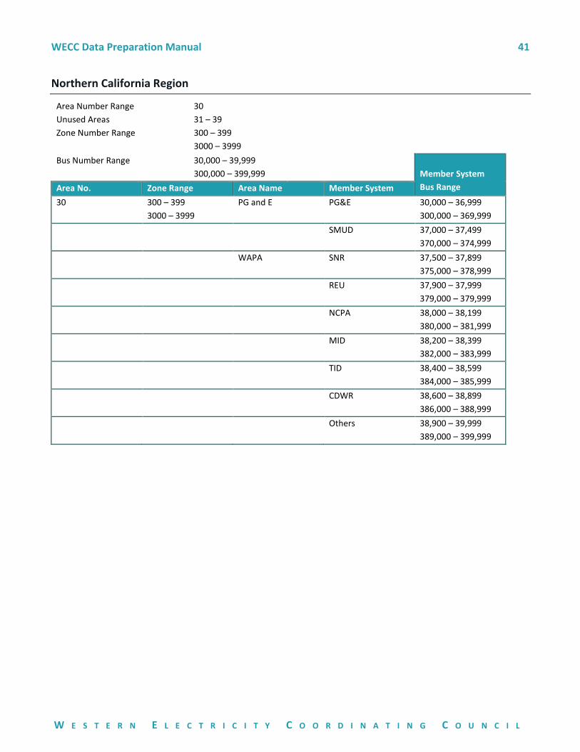
WECC Data Preparation Manual 41
W E S T E R N E L E C T R I C I T Y C O O R D I N A T I N G C O U N C I L
Northern California Region
Area Number Range 30
Unused Areas 31 – 39
Zone Number Range 300 – 399
3000 – 3999
Bus Number Range 30,000 – 39,999
300,000 – 399,999
Member System
Bus Range Area No. Zone Range Area Name Member System
30 300 – 399
3000 – 3999
PG and E PG&E 30,000 – 36,999
300,000 – 369,999
SMUD 37,000 – 37,499
370,000 – 374,999
WAPA SNR 37,500 – 37,899
375,000 – 378,999
REU 37,900 – 37,999
379,000 – 379,999
NCPA 38,000 – 38,199
380,000 – 381,999
MID 38,200 – 38,399
382,000 – 383,999
TID 38,400 – 38,599
384,000 – 385,999
CDWR 38,600 – 38,899
386,000 – 388,999
Others 38,900 – 39,999
389,000 – 399,999
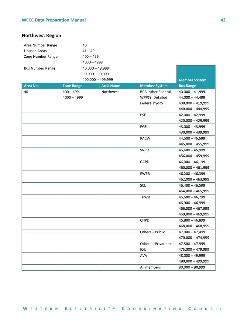
WECC Data Preparation Manual 42
W E S T E R N E L E C T R I C I T Y C O O R D I N A T I N G C O U N C I L
Northwest Region
Area Number Range 40
Unused Areas 41 – 49
Zone Number Range 400 – 499
4000 – 4999
Bus Number Range 40,000 – 49,999
90,000 – 90,999
400,000 – 499,999
Member System
Bus Range Area No. Zone Range Area Name Member System
40 400 – 499
4000 – 4999
Northwest BPA, other Federal,
WPPSS, Detailed
Federal hydro
40,000 – 41,999
44,000 – 44,499
400,000 – 419,999
440,000 – 444,999
PSE 42,000 – 42,999
420,000 – 429,999
PGE 43,000 – 43,999
430,000 – 439,999
PACW 44,500 – 45,599
445,000 – 455,999
SNPD 45,600 – 45,999
456,000 – 459,999
GCPD 46,000 – 46,199
460,000 – 461,999
EWEB 46,200 – 46,399
462,000 – 463,999
SCL 46,400 – 46,599
464,000 – 465,999
TPWR 46,600 – 46,799
46,900 – 46,999
466,000 – 467,999
469,000 – 469,999
CHPD 46,800 – 46,899
468,000 – 468,999
Others – Public 47,000 – 47,499
470,000 – 474,999
Others – Private or
IOU
47,500 – 47,999
475,000 – 479,999
AVA 48,000 – 49,999
480,000 – 499,999
All members 90,000 – 90,999
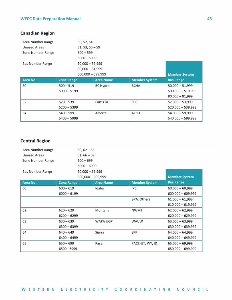
WECC Data Preparation Manual 43
W E S T E R N E L E C T R I C I T Y C O O R D I N A T I N G C O U N C I L
Canadian Region
Area Number Range 50, 52, 54
Unused Areas 51, 53, 55 – 59
Zone Number Range 500 – 599
5000 – 5999
Bus Number Range 50,000 – 59,999
80,000 – 81,999
500,000 – 599,999
Member System
Bus Range Area No. Zone Range Area Name Member System
50 500 – 519
5000 – 5199
BC Hydro BCHA 50,000 – 51,999
500,000 – 519,999
80,000 – 81,999
52 520 – 539
5200 – 5399
Fortis BC FBC 52,000 – 53,999
520,000 – 539,999
54 540 – 599
5400 – 5999
Alberta AESO 54,000 – 59,999
540,000 – 599,999
Central Region
Area Number Range 60, 62 – 65
Unused Areas 61, 66 – 69
Zone Number Range 600 – 699
6000 – 6999
Bus Number Range 60,000 – 69,999
600,000 – 699,999
Member System
Bus Range Area No. Zone Range Area Name Member System
60 600 – 619
6000 – 6199
Idaho IPC 60,000 – 60,999
600,000 – 609,999
BPA, Others 61,000 – 61,999
610,000 – 619,999
62 620 – 629
6200 – 6299
Montana NWMT 62,000 – 62,999
620,000 – 629,999
63 630 – 639
6300 – 6399
WAPA UGP WAUW 63,000 – 63,999
630,000 – 639,999
64 640 – 649
6400 – 6499
Sierra SPP 64,000 – 64,999
640,000 – 649,999
65 650 – 699
6500 - 6999
Pace PACE-UT, WY, ID 65,000 – 69,999
650,000 – 699,999
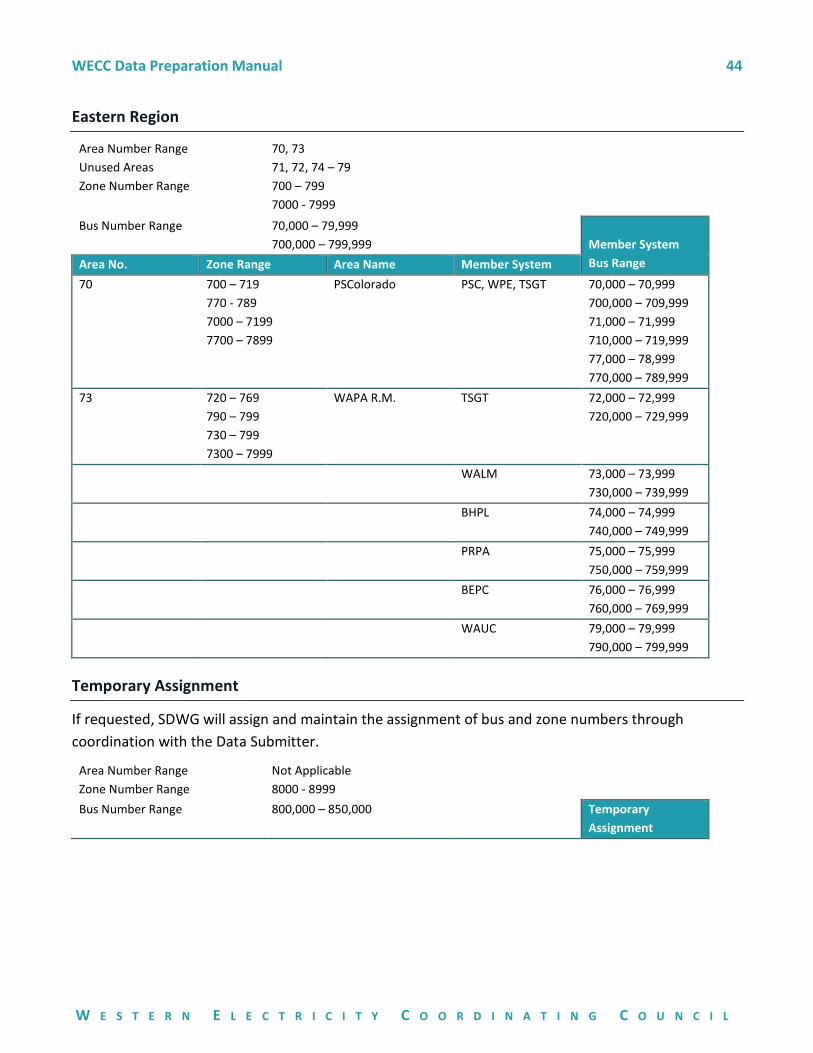
WECC Data Preparation Manual 44
W E S T E R N E L E C T R I C I T Y C O O R D I N A T I N G C O U N C I L
Eastern Region
Area Number Range 70, 73
Unused Areas 71, 72, 74 – 79
Zone Number Range 700 – 799
7000 - 7999
Bus Number Range 70,000 – 79,999
700,000 – 799,999
Member System
Bus Range Area No. Zone Range Area Name Member System
70 700 – 719
770 - 789
7000 – 7199
7700 – 7899
PSColorado PSC, WPE, TSGT 70,000 – 70,999
700,000 – 709,999
71,000 – 71,999
710,000 – 719,999
77,000 – 78,999
770,000 – 789,999
73 720 – 769
790 – 799
730 – 799
7300 – 7999
WAPA R.M. TSGT 72,000 – 72,999
720,000 – 729,999
WALM 73,000 – 73,999
730,000 – 739,999
BHPL 74,000 – 74,999
740,000 – 749,999
PRPA 75,000 – 75,999
750,000 – 759,999
BEPC 76,000 – 76,999
760,000 – 769,999
WAUC 79,000 – 79,999
790,000 – 799,999
Temporary Assignment
If requested, SDWG will assign and maintain the assignment of bus and zone numbers through
coordination with the Data Submitter.
Area Number Range Not Applicable
Zone Number Range 8000 - 8999
Bus Number Range 800,000 – 850,000
Temporary
Assignment
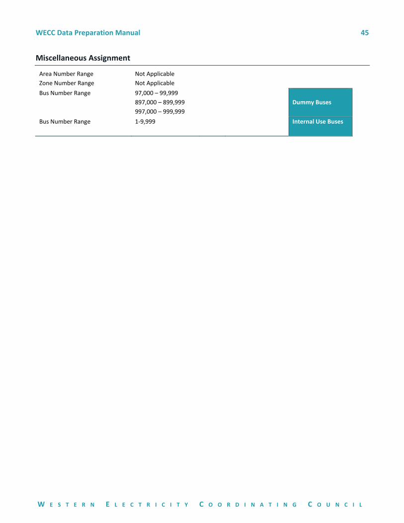
WECC Data Preparation Manual 45
W E S T E R N E L E C T R I C I T Y C O O R D I N A T I N G C O U N C I L
Miscellaneous Assignment
Area Number Range Not Applicable
Zone Number Range Not Applicable
Bus Number Range 97,000 – 99,999
897,000 – 899,999
997,000 – 999,999
Dummy Buses
Bus Number Range 1-9,999
Internal Use Buses
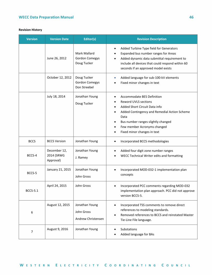
WECC Data Preparation Manual 46
W E S T E R N E L E C T R I C I T Y C O O R D I N A T I N G C O U N C I L
Revision History
Version Version Date Editor(s) Revision Description
June 26, 2012
Mark Mallard
Gordon Comegys
Doug Tucker
• Added Turbine Type field for Generators
• Expanded bus number ranges for Areas
• Added dynamic data submittal requirement to
include all devices that could respond within 60
seconds if an approved model exists
October 12, 2012 Doug Tucker
Gordon Comegys
Don Streebel
• Added language for sub-100-kV elements
• Fixed minor changes in text
July 18, 2014 Jonathan Young
Doug Tucker
• Accommodate BES Definition
• Reword UVLS sections
• Added Short Circuit Data info
• Added Contingency and Remedial Action Scheme
Data
• Bus number ranges slightly changed
• Few member Acronyms changed
• Fixed minor changes in text
BCCS BCCS Version Jonathan Young • Incorporated BCCS methodologies
BCCS-4
December 12,
2014 (SRWG
Approval)
Jonathan Young
J. Ramey
• Added four digit zone number ranges
• WECC Technical Writer edits and formatting
BCCS-5 January 21, 2015 Jonathan Young
John Gross
• Incorporated MOD-032-1 implementation plan
concepts
BCCS-5.1
April 24, 2015 John Gross • Incorporated PCC comments regarding MOD-032
implementation plan approach. PCC did not approve
version BCCS-5.
6
August 12, 2015 Jonathan Young
John Gross
Andrew Christensen
• Incorporated TSS comments to remove direct
references to modeling standards.
• Removed references to BCCS and reinstated Master
Tie-Line File language.
7 August 9, 2016 Jonathan Young • Substations
• Added language for BAs
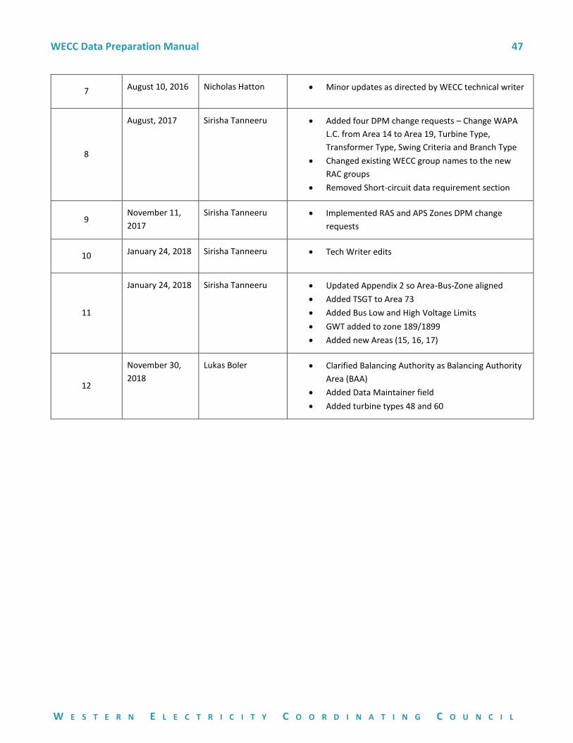
WECC Data Preparation Manual 47
W E S T E R N E L E C T R I C I T Y C O O R D I N A T I N G C O U N C I L
7 August 10, 2016 Nicholas Hatton • Minor updates as directed by WECC technical writer
8
August, 2017 Sirisha Tanneeru • Added four DPM change requests – Change WAPA
L.C. from Area 14 to Area 19, Turbine Type,
Transformer Type, Swing Criteria and Branch Type
• Changed existing WECC group names to the new
RAC groups
• Removed Short-circuit data requirement section
9 November 11,
2017
Sirisha Tanneeru • Implemented RAS and APS Zones DPM change
requests
10 January 24, 2018 Sirisha Tanneeru • Tech Writer edits
11
January 24, 2018 Sirisha Tanneeru • Updated Appendix 2 so Area-Bus-Zone aligned
• Added TSGT to Area 73
• Added Bus Low and High Voltage Limits
• GWT added to zone 189/1899
• Added new Areas (15, 16, 17)
12
November 30,
2018
Lukas Boler • Clarified Balancing Authority as Balancing Authority
Area (BAA)
• Added Data Maintainer field
• Added turbine types 48 and 60


![WECC Data Preparation Manual with BCCS - MOD … · Web view2 = generator bus (voltage control [terminal or remote] within generator limits) 2 = generator bus with unlimited reactive](https://img.pdfslide.us/doc/110x75/5e7141d2f546c431ac535587/wecc-data-preparation-manual-with-bccs-mod-web-view-2-generator-bus-voltage.jpg)