Embed Size (px)
Citation preview
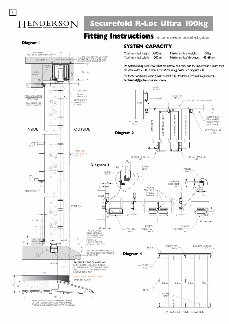
Securefold R-Loc Ultra 100kg
Fitting Instructions for top hung exterior outward folding doors
SYSTEM CAPACITYMaximum leaf height- 3300mm Maximum leaf weight- 100kgMaximum leaf width- 1000mm Maximum leaf thickness- 45-68mm
On systems using door leaves that are narrow and thick and the hypotenuse is more thanthe door width x 1.004 then a risk of camming exists (see diagram 13).
For thicker or thinner doors please contact P C Henderson Technical Department [email protected]
JAMB CAP GASKET
ALTERNATIVE ALUMINIUM THRESHOLD SF94T BY PCH - COMES COMPLETE WITH 94P ANDENDCAPS AND IS PREDRILLED FOR DRAINAGE
WHEN USED IN CONJUNCTION WITHALUMINIUM SUPPORT CHANNEL 94SCTHE OUTER CHANNEL DIMENSIONSBECOME 23H x 25W
JAMB CAP IN LINE WITH TRACK
52
212
140
34
39
JAMB CAPIN LINE WITH TRACK
Diagram 1
Diagram 2
Diagram 3
INSIDE OUTSIDE
Diagram 4
HENDERSON1

PREPARATIONSFU1 - Pivot Assembly SetSF2R - End Hanger Set Right Hand - for doors meeting a swing door and square-edged doors meetingSF2L - End Hanger Set Left Hand - for doors meeting a swing door and square-edged doors meetingSFU2R - End Hanger Set Right Hand - for doors folding to the frame (i.e. 2 leaf, 4 leaf and 6 leaf)SFU2L - End Hanger Set Left Hand - for doors folding to the frame (i.e. 2 leaf, 4 leaf and 6 leaf)SF3 - Hinge Set with HandleSFU4 - Intermediate Hanger SetSF7 - Hinge Set Offset Outward OpeningSF8 - Rebated End Hanger MeetingSFU9 - Pivot Hinge required for Ultra securitySF10 - Face Fix Handle (Optional)
Diagram 5
Diagram 6
SFU1 SFU4
SFU4 SFU4
SF2L SFU1 SFU1
SFU1 SFU1
SFU4 SFU4SFU1
SFU1 SFU4 SF2L SFU4 SFU4SFU4 SFU1
SFU1 SFU4
SFU4 SFU4
SFU2L
SFU2L
SFU1 SFU1 SFU1 SFU1
SFU4 SF2RSFU1
SFU9 SFU9
SFU9
SFU9SFU9 SFU9 SFU9 SFU9 SFU9
SFU9SFU9
SFU9SFU9SFU9
SFU1
SFU1
SFU2L
SFU9 SFU9SF3
SF3
SF7 SF7
SF7 SF7SFU9
SFU1
DOOR HARDWARE - KIT ORIENTATION, OUTWARD OPENING ONLY
2
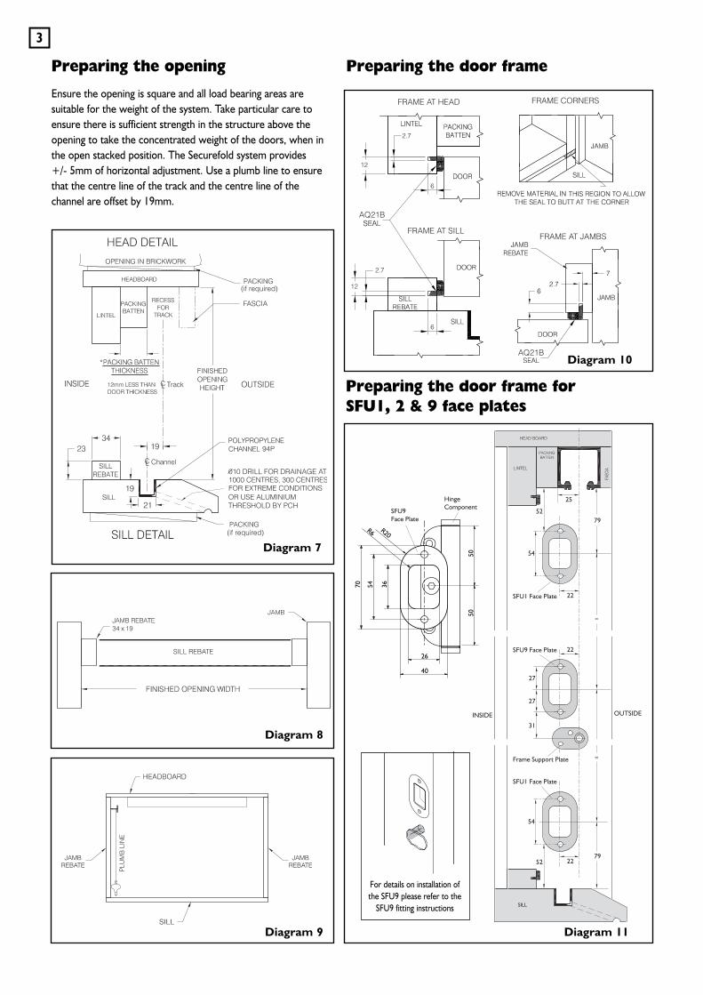
Preparing the opening
Ensure the opening is square and all load bearing areas aresuitable for the weight of the system. Take particular care toensure there is sufficient strength in the structure above theopening to take the concentrated weight of the doors, when inthe open stacked position. The Securefold system provides +/- 5mm of horizontal adjustment. Use a plumb line to ensurethat the centre line of the track and the centre line of thechannel are offset by 19mm.
Diagram 7
Diagram 8
Diagram 9
3
=
=
For details on installation ofthe SFU9 please refer to the
SFU9 fitting instructions
Preparing the door frame
Preparing the door frame forSFU1, 2 & 9 face plates
INSIDE OUTSIDE
SFU9Face Plate
Frame Support Plate
HingeComponent
7952
52
54
27
27
31
79
22
25
22
22
SILL
=
=
5050
70
26
R20R6
54 36
40
54
SFU1 Face Plate
SFU9 Face Plate
SFU1 Face Plate
Diagram 10
Diagram 11
ADD 10mm TOWIDTH OF ENDHANGER LEAFFOR REBATE
ADD 10mm TOWIDTH OF EACHLEAF TO CREATEREBATE
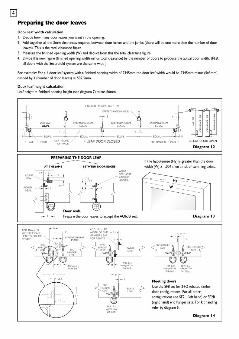
Preparing the door leaves
Door leaf width calculation1. Decide how many door leaves you want in the opening.2. Add together all the 3mm clearances required between door leaves and the jambs (there will be one more than the number of door
leaves). This is the total clearance figure.3. Measure the finished opening width (W) and deduct from this the total clearance figure.4. Divide this new figure (finished opening width minus total clearance) by the number of doors to produce the actual door width. (N.B.
all doors with the Securefold system are the same width).
For example: For a 4 door leaf system with a finished opening width of 2345mm the door leaf width would be 2345mm minus (5x3mm)divided by 4 (number of door leaves) = 582.5mm.
Door leaf height calculationLeaf height = finished opening height (see diagram 7) minus 66mm.
Diagram 12
Diagram 13
Diagram 14
Meeting doorsUse the SF8 set for 2+2 rebated timberdoor configurations. For all otherconfigurations use SF2L (left hand) or SF2R(right hand) end hanger sets. For kit handingrefer to diagram 6.
4
Door sealsPrepare the door leaves to accept the AQ63B seal.
If the hypotenuse (Hy) is greater than the doorwidth (W) x 1.004 then a risk of camming exists.
PREPARING THE DOOR LEAF
AT THE JAMB BETWEEN DOOR EDGES
Hy
W
SFU1 SFU4 SFU2L
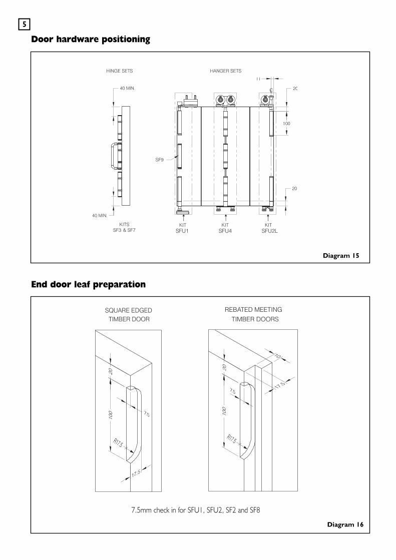
7.5mm check In for SFU1, SFU2, SF2 and SF8
Door hardware positioning
End door leaf preparation
Diagram 15
Diagram 16
5
7.5mm check in for SFU1, SFU2, SF2 and SF8
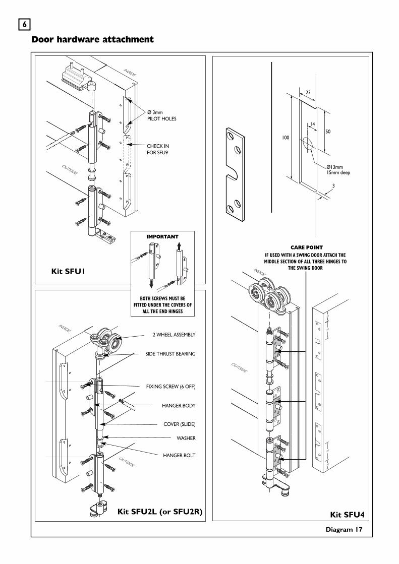
Door hardware attachment
Diagram 17
6
CHECK INFOR SFU9
23
1450
3
100
Ø13mm15mm deep
Ø 3mmPILOT HOLES
Kit SFU4
2 WHEEL ASSEMBLY
SIDE THRUST BEARING
FIXING SCREW (6 OFF)
HANGER BODY
COVER (SLIDE)
WASHER
HANGER BOLT
Kit SFU2L (or SFU2R)
Kit SFU1
BOTH SCREWS MUST BEFITTED UNDER THE COVERS OF
ALL THE END HINGES
IMPORTANT
18
3
22
100
50
15
IF USED WITH A SWING DOOR ATTACH THEMIDDLE SECTION OF ALL THREE HINGES TO
THE SWING DOOR
CARE POINT
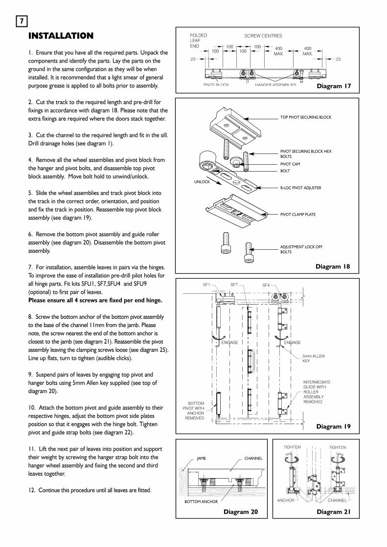
INSTALLATION
1. Ensure that you have all the required parts. Unpack thecomponents and identify the parts. Lay the parts on theground in the same configuration as they will be wheninstalled. It is recommended that a light smear of generalpurpose grease is applied to all bolts prior to assembly.
2. Cut the track to the required length and pre-drill forfixings in accordance with diagram 18. Please note that theextra fixings are required where the doors stack together.
3. Cut the channel to the required length and fit in the sill.Drill drainage holes (see diagram 1).
4. Remove all the wheel assemblies and pivot block fromthe hanger and pivot bolts, and disassemble top pivotblock assembly. Move bolt hold to unwind/unlock.
5. Slide the wheel assemblies and track pivot block intothe track in the correct order, orientation, and positionand fix the track in position. Reassemble top pivot blockassembly (see diagram 19).
6. Remove the bottom pivot assembly and guide rollerassembly (see diagram 20). Disassemble the bottom pivotassembly.
7. For installation, assemble leaves in pairs via the hinges.To improve the ease of installation pre-drill pilot holes forall hinge parts. Fit kits SFU1, SF7,SFU4 and SFU9(optional) to first pair of leaves. Please ensure all 4 screws are fixed per end hinge.
8. Screw the bottom anchor of the bottom pivot assemblyto the base of the channel 11mm from the jamb. Pleasenote, the screw nearest the end of the bottom anchor isclosest to the jamb (see diagram 21). Reassemble the pivotassembly leaving the clamping screws loose (see diagram 25).Line up flats, turn to tighten (audible clicks).
9. Suspend pairs of leaves by engaging top pivot andhanger bolts using 5mm Allen key supplied (see top ofdiagram 20).
10. Attach the bottom pivot and guide assembly to theirrespective hinges, adjust the bottom pivot side platesposition so that it engages with the hinge bolt. Tightenpivot and guide strap bolts (see diagram 22).
11. Lift the next pair of leaves into position and supporttheir weight by screwing the hanger strap bolt into thehanger wheel assembly and fixing the second and thirdleaves together.
12. Continue this procedure until all leaves are fitted.
7
Diagram 17
Diagram 19
Diagram 18
Diagram 20
BOTTOM ANCHOR
CHANNEL
TOP PIVOT SECURING BLOCK
PIVOT SECURING BLOCK HEXBOLTS
PIVOT CAM
R-LOC PIVOT ADJUSTER
PIVOT CLAMP PLATE
ADJUSTMENT LOCK OFFBOLTS
JAMB
Diagram 21
BOLT
UNLOCK
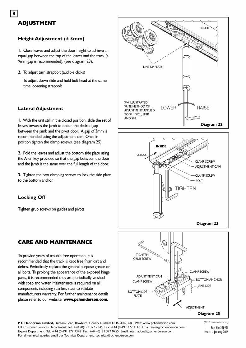
Diagram 25
ADJUSTMENT
8
ADJUSTMENT
CLAMP SCREW
BOTTOM ANCHOR
JAMB SIDE
BOTTOM SIDEPLATE
CLAMP SCREW
ADJUSTMENT CAM
TIGHTENGRUB SCREW
Height Adjustment (± 3mm)
1. Close leaves and adjust the door height to achieve anequal gap between the top of the leaves and the track (a9mm gap is recommended). (see diagram 23).
2. To adjust turn strapbolt (audible clicks)
To adjust down slide and hold bolt head at the sametime loosening strapbolt
Lateral Adjustment
1. With the unit still in the closed position, slide the set ofleaves towards the jamb to obtain the desired gapbetween the jamb and the pivot door. A gap of 3mm isrecommended using the adjustment cam. Once inposition tighten the clamp screws. (see diagram 25).
2. Fold the leaves and adjust the bottom side plate usingthe Allen key provided so that the gap between the doorand the jamb is the same over the full length of the door.
3. Tighten the two clamping screws to lock the side plateto the bottom anchor.
Locking Off
Tighten grub screws on guides and pivots.
CARE AND MAINTENANCE
To provide years of trouble free operation, it isrecommended that the track is kept free from dirt anddebris. Periodically replace the general purpose grease onall bolts. To prolong the appearance of the exposed hingeparts, it is recommended they are periodically washedwith soap and water. Maintenance is required on allcomponents including stainless steel to validatemanufacturers warranty. For further maintenance detailsplease refer to our website, www.pchenderson.com.
(All dimensions in mm)P C Henderson Limited, Durham Road, Bowburn, County Durham DH6 5NG, UK. Web: www.pchenderson.comUK Customer Services Department: Tel: +44 (0)191 377 7345 Fax: +44 (0)191 377 3116 Email: [email protected] Department: Tel: +44 (0)191 377 7346 Fax: +44 (0)191 377 0755. Email: [email protected] all technical queries email our Technical Department: [email protected]
Part No: 298991Issue 1 - January 2016
Diagram 22
Diagram 23
CLAMP SCREW
CLAMP SCREW
BOLT
ADJUSTMENT CAM
LINE UP FLATS
INSIDE
SF4 ILLUSTRATED.SAME METHOD OFADJUSTMENT APPLIEDTO SF1, SF2L, SF2RAND SF8.
INSIDE
UNLOCK
FLATS TO LINE UP(IMAGE TO EDIT DIAGRAM 22)

![!@ a'wjf/, ( k '; @)&^ Wednesday, 25 December 2019 ;+3Lo ... 12 page col… · !@dfrf/ a'wjf/, ( k '; @)&^ | Wednesday, 25 December 2019 lh=k|=sf=sf7=b=g += &÷)^@÷^#, d=If ]=x '=b=g](https://img.pdfslide.us/doc/110x75/5ecbc514aab05a781359bfe8/-awjf-k-wednesday-25-december-2019-3lo-12-page-col-dfrf.jpg)


![INSTBWC1 REV A - APR 2012 Weatherfold 4c 75 · JW - 35[1.38] H JW - (PW + 16[0.62]) HEADBOARD 981 CHANNEL 980 SILL JAMB [15.75] 400 X X = 20[0.79] X X [3.94] 100 [3.94] 100 PIVOT](https://img.pdfslide.us/doc/110x75/5fa3c5883a47545532290d09/instbwc1-rev-a-apr-2012-weatherfold-4c-75-jw-35138-h-jw-pw-16062.jpg)


![CH2M HILL HEALTH AND SAFETY PLAN · HEALTH AND SAFETY PLAN VERSION 1.2 GWP_HSP_VER1.2.DOC SEPTEMBER 2005 [This page intentionally left blank.] 005937. MW-1 GWMW03 CLC Well 18 MW-SF7](https://img.pdfslide.us/doc/110x75/5ffbc551fc22b541ea1b92d9/ch2m-hill-health-and-safety-plan-health-and-safety-plan-version-12-gwphspver12doc.jpg)


![INSTBWS1 REV G - APR 2012 Weatherfold 4s 50, 75 & 100...hangers by removing track section Clamp plate covers notch in track 56[2.21] CUT TRACK 40[1.58] 40[1.58] 19[0.75] HEADBOARD](https://img.pdfslide.us/doc/110x75/60d1181ab2917c2ed2040182/instbws1-rev-g-apr-2012-weatherfold-4s-50-75-100-hangers-by-removing.jpg)