Embed Size (px)
Citation preview
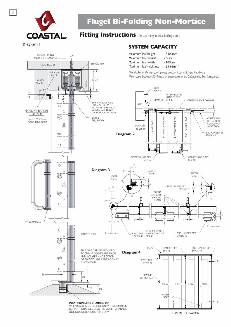
Flugel Bi-Folding Non-Mortice
Fitting Instructions for top hung interior folding doors
SYSTEM CAPACITYMaximum leaf height - 3300mmMaximum leaf weight - 50kgMaximum leaf width - 1000mmMaximum leaf thickness - 35-68mm*
*For thicker or thinner doors please contact Coastal Joinery Hardware**For doors between 35-44mm an alternative to the CoGlide flushbolt is required.
TRACK 180
47
43 45
23
2019
9
THIS GAP CAN BE REDUCEDTO 5MM IF DOORS ARE MADE4MM LONGER AND BOTTOMOF PIVOT/GUIDES ARE LOCALLYCHECKED IN
POLYPROPYLENE CHANNEL 94PWHEN USED IN CONJUNCTION WITH ALUMINIUMSUPPORT CHANNEL 94SC THE OUTER CHANNELDIMENSIONS BECOME 23H x 25W
TRACK FIXING(NOT BY COASTAL)
OFFSET HINGE SETSF7-45
END HANGER SETSFW2L-45
END HANGER SETSFW2L-45
END HANGER SETSFW2L-45
INTERMEDIATEHANGER SETSF4-45
INTERMEDIATEHANGER SETSF4-45
HANGER SETSF4-45
OFFSET HINGE SETSF7-45
OFFSET HINGE SETSF7-45
PIVOT SETSFW1-45
PIVOT SETSFW1-45
PIVOT SETSFW1-45
SFW9-45
OFFSET HINGE SETSF7-45
END HANGER SETSFW2L-45
END HANGER SETSFW2L-45
END HANGER SETSFW2L-45
INTERMEDIATEHANGER SETSF4-45
INTERMEDIATEHANGER SETSF4-45
HANGER SETSF4-45
OFFSET HINGE SETSF7-45
OFFSET HINGE SETSF7-45
PIVOT SETSFW1-45
PIVOT SETSFW1-45
PIVOT SETSFW1-45
SFW9-45
OFFSET HINGE SETSF7-45
END HANGER SETSFW2L-45
END HANGER SETSFW2L-45
END HANGER SETSFW2L-45
INTERMEDIATEHANGER SETSF4-45
INTERMEDIATEHANGER SETSF4-45
HANGER SETSF4-45
OFFSET HINGE SETSF7-45
OFFSET HINGE SETSF7-45
PIVOT SETSFW1-45
PIVOT SETSFW1-45
PIVOT SETSFW1-45
SFW9-45
Diagram 1
Diagram 2
Diagram 3
Diagram 4
1

PIVOT SET KITSFW1-45
FOLDING DIRECTION
SFW9-45(OPTIONAL)
INTERMEDIATEHANGER SET KITSF4-45
END HANGER SET KITSFW2L-45SFW2R-45
PREPARATIONSFW1 - 45 Pivot Assembly SetSFW2R - 45 End Hanger Set Right HandSFW2L - 45 End Hanger Set Left HandSF3 - 45 Hinge Set with HandleSF4 - 45 Intermediate Hanger SetSF5 - 45 Hinge Set Inward OpeningSF6 - 45 Hinge Set Offset Inward OpeningSF7 - 45 Hinge Set Offset Outward OpeningSFW8 - 45 Rebated End Hanger MeetingSFW9 - 45 Pivot Hinge for Doors Over 2200mm High (Optional)SF10 - 45 Face Fix Handle (Optional)
Diagram 5
Diagram 6
SFW1-45SFW1-45SFW2L-45SFW2L-45 SFW1-45SFW1-45SFW1-45SFW1-45
SFW1-45
SFW1-45 SFW1-45SFW1-45 SFW1-45 SFW1-45 SFW1-45SF4-45
SFW1-45 SF4-45 SFW1-45 SF4-45 SFW1-45 SF4-45 SF4-45SF4-45
SF4-45 SF4-45SF4-45
SFW1-45 SFW1-45 SFW1-45 SFW1-45SFW1-45SFW8-45 SFW8-45
SF3-45
SF3-45 SF3-45 SF3-45 SF3-45SF7-45 SF7-45 SF7-45
SF3-45 SF7-45
SF7-45
SF7-45 SF7-45 SF7-45 SF3-45 SF7-45 SF7-45SF3-45
SF7-45 SF7-45 SF7-45 SF3-45
SF7-45 SF7-45
SF4-45SF4-45SF4-45
SFW2R-45SF4-45 SF4-45
SFW2L-45
SFW2L-45 SFW2L-45
SFW1-45SFW1-45
SFW1-45
SFW1-45 SFW1-45 SFW1-45 SFW1-45SFW1-45 SFW1-45SF4-45
SFW1-45 SF4-45 SFW1-45 SFW1-45SF4-45 SF4-45 SF4-45 SF4-45
SF4-45 SF4-45 SF4-45
SFW1-45 SFW1-45 SFW1-45SFW1-45SFW1-45SFW8-45 SFW8-45
SF5-45
SF5-45 SF5-45 SF5-45
SF5-45
SF5-45SF6-45
SF6-45
SF6-45 SF6-45 SF6-45 SF6-45 SF6-45SF5-45 SF5-45
SF6-45 SF6-45 SF6-45
SF6-45 SF6-45
SF5-45 SF6-45 SF6-45 SF6-45
SF4-45SFW2R-45 SFW1-45 SFW1-45 SFW1-45 SF4-45 SF4-45SFW1-45SFW2R-45
SFW2L-45SF4-45 SF4-45
SFW2R-45
SFW2R-45 SFW2R-45
2
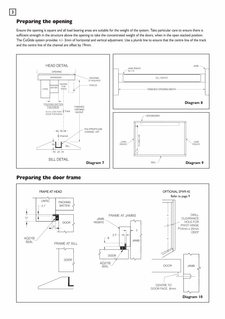
Preparing the opening
Ensure the opening is square and all load bearing areas are suitable for the weight of the system. Take particular care to ensure there issufficient strength in the structure above the opening to take the concentrated weight of the doors, when in the open stacked position.The CoGlide system provides +/- 3mm of horizontal and vertical adjustment. Use a plumb line to ensure that the centre line of the trackand the centre line of the channel are offset by 19mm.
Preparing the door frame
Diagram 7
Diagram 8
Diagram 9
Diagram 10
3
Refer to page 9OPTIONAL SFW9-45FRAME AT HEAD
Preparing the door leaves
Door leaf width calculation1. Decide how many door leaves you want in the opening.2. Add together all the 3mm clearances required between door leaves and the jambs (there will be one more than the number of door
leaves). This is the total clearance figure.3. Measure the finished opening width (W) and deduct from this the total clearance figure.4. Divide this new figure (finished opening width minus total clearance) by the number of doors to produce the actual door width. (N.B.
all doors with the CoGlide system are the same width).
For example: For a 4 door leaf system with a finished opening width of 2345mm the door leaf width would be 2345mm minus (5x3mm)divided by 4 (number of door leaves) = 582.5mm.
Door leaf height calculationLeaf height = finished opening height (see diagram 7) minus 66mm.
Diagram 11
Diagram 12
Door SealsPrepare the door leaves to accept theAQ63B seal.
4
PREPARING THE DOOR LEAF
AT THE JAMB BETWEEN DOOR EDGES
Diagram 13
Meeting DoorsUse the SFW8-45 set for 2+2, 4+4, plusother multiples of rebated and squareedge timber door configurations.
21 321 33
3
3
SFW2L-45 End hangerdoor set (Left)
SFW2L-45 End hangerdoor set (Left)
SFW8-45 Meetingdoor set
SFW8-45 Meetingdoor set
Add 10mm to thewidth of each leafto create rebate
ENDHANGERLEAF
ENDHANGER
LEAF
ENDHANGER LEAF
ENDHANGER
LEAF
ENDHANGERLEAF
SWINGLEAF
ENDHANGER LEAF
SWINGLEAF
11 11
11
11
Add 10mm to thewidth of each leafto create rebate
Door hardware positioning
Diagram 14
5
End door leaf preparation
Diagram 15
7.5mm check In for SF1, SF2 and SF8
25
Square edged timber door Rebated meeting timber doors
25
20
10
20
100
100
KIT SFW1-45KITS SF3-45, SF5-45,SF6-45 & SF7-45
SFW9-45
KIT SF4-45 KIT SFW2L-45 & KIT SFW2R-45
6
Door hardware attachment
Diagram 16
OUTSIDEINSIDE
OUTSIDEINSIDE
OUTSIDE
INSIDE
OUTSIDE
INSIDE
Kit SFW8-45 Kit SF4-45
Kit SFW2L -45(or SFW2R-45)Kit SFW1-45
SFW1-45 SF7-45 SF4-45
INSTALLATION
1. Ensure that you have all the required parts. Unpack thecomponents and identify the parts. Lay the parts on theground in the same configuration as they will be wheninstalled. It is recommended that a light smear of generalpurpose grease is applied to all bolts prior to assembly.
2. Cut the track to the required length and pre-drill forfixings in accordance with diagram 17. Please note that theextra fixings are required where the doors stack together.
3. Cut the channel to the required length and fit in the sill.Drill drainage holes (see diagram 1).
4. Remove all the wheel assemblies and pivot block fromthe hanger and pivot bolts, and disassemble top pivotblock assembly.
5. Slide the wheel assemblies and track pivot block intothe track in the correct order, orientation, and positionand fix the track in position. Reassemble top pivot blockassembly (see diagram 18).
6. Remove the bottom pivot assembly and guide rollerassembly (see diagram 19). Disassemble the bottom pivotassembly.
7. For installation, assemble leaves in pairs via the hinges.To improve the ease of installation pre-drill pilot holes forall hinge parts. Fit kits SFW1-45, SF7-45,SF4-45 andSFW9-45 (optional) to first pair of leaves. Please ensure all 4 screws are fixed per end hinge.
8. Screw the bottom anchor of the bottom pivot assemblyto the base of the channel 11mm from the jamb. Pleasenote, the screw nearest the end of the bottom anchor isclosest to the jamb (see diagram 20). Reassemble the pivotassembly leaving the clamping screws loose (see diagram 24).
9. Suspend pairs of leaves by engaging top pivot andhanger bolts using 5mm allen key supplied (see top ofdiagram 19).
10. Attach the bottom pivot and guide assembly to theirrespective hinges, adjust the bottom pivot side platesposition so that it engages with the hinge bolt. Tightenpivot and guide strap bolts (see diagram 21).
11. Lift the next pair of leaves into position and supporttheir weight by screwing the hanger strap bolt into thehanger wheel assembly and fixing the second and thirdleaves together.
12. Continue this procedure until all leaves are fitted.
Diagram 17
Diagram 19
Diagram 18
Diagram 20
BOTTOM ANCHOR
CHANNEL
TOP PIVOT SECURING BLOCK
PIVOT SECURING BLOCK HEXBOLTS
PIVOT CAM
PIVOT ADJUSTER
PIVOT CLAMP PLATE
ADJUSTMENT LOCK OFFBOLTS
JAMB
Diagram 21
7
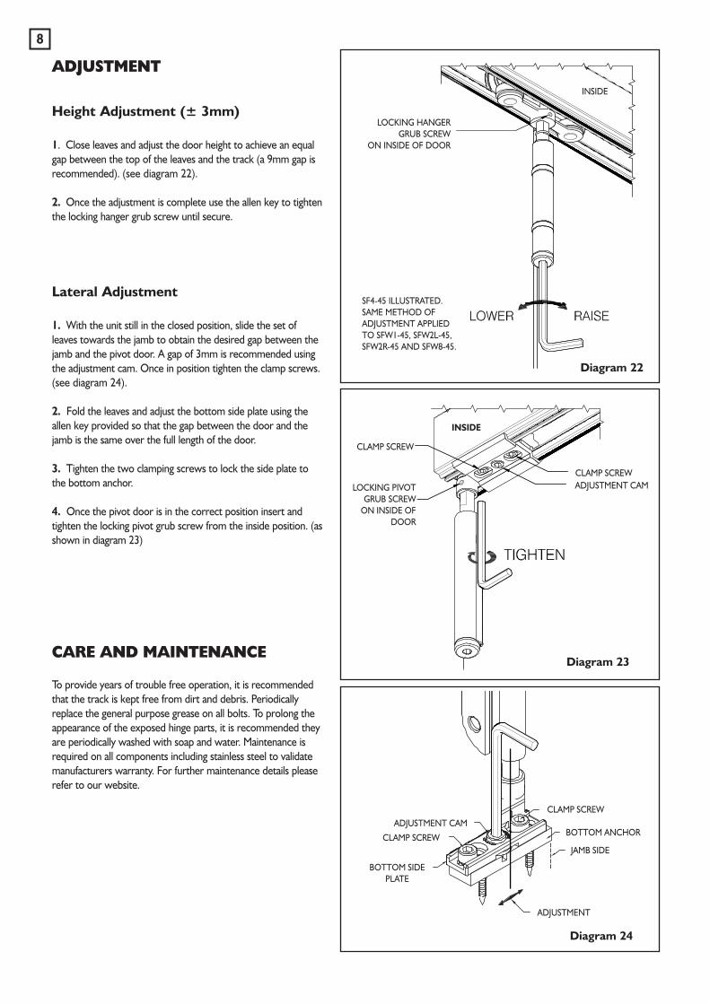
Diagram 22
Diagram 23
Diagram 24
ADJUSTMENT
8
ADJUSTMENT
CLAMP SCREW
BOTTOM ANCHOR
JAMB SIDE
BOTTOM SIDEPLATE
CLAMP SCREW
CLAMP SCREW
CLAMP SCREW
ADJUSTMENT CAM
ADJUSTMENT CAM
LOCKING HANGERGRUB SCREW
ON INSIDE OF DOOR
INSIDE
SF4-45 ILLUSTRATED.SAME METHOD OFADJUSTMENT APPLIEDTO SFW1-45, SFW2L-45,SFW2R-45 AND SFW8-45.
LOCKING PIVOTGRUB SCREW
ON INSIDE OFDOOR
Height Adjustment (± 3mm)
1. Close leaves and adjust the door height to achieve an equalgap between the top of the leaves and the track (a 9mm gap isrecommended). (see diagram 22).
2. Once the adjustment is complete use the allen key to tightenthe locking hanger grub screw until secure.
Lateral Adjustment
1. With the unit still in the closed position, slide the set ofleaves towards the jamb to obtain the desired gap between thejamb and the pivot door. A gap of 3mm is recommended usingthe adjustment cam. Once in position tighten the clamp screws.(see diagram 24).
2. Fold the leaves and adjust the bottom side plate using theallen key provided so that the gap between the door and thejamb is the same over the full length of the door.
3. Tighten the two clamping screws to lock the side plate tothe bottom anchor.
4. Once the pivot door is in the correct position insert andtighten the locking pivot grub screw from the inside position. (asshown in diagram 23)
CARE AND MAINTENANCE
To provide years of trouble free operation, it is recommendedthat the track is kept free from dirt and debris. Periodicallyreplace the general purpose grease on all bolts. To prolong theappearance of the exposed hinge parts, it is recommended theyare periodically washed with soap and water. Maintenance isrequired on all components including stainless steel to validatemanufacturers warranty. For further maintenance details pleaserefer to our website.
INSIDE
SFW9-45 Intermediate Pivot Set
SFW1-45
SFW1-45
SFW9-45
Diagram 2.Diagram 1.
Diagram 3.
Diagram 5.
1. The CoGlide SFW9-45 intermediate pivot set shown in Diagram 1, shouldbe fitted to the pivot door approximately mid way between the SFW1-45top and bottom pivot assemblies. The SFW9-45 hinge must be positionedon the same centre line as the SFW1-45 top and bottom pivot hingebodies.
2. Prepare the frame for the opening by drilling a Ø12mm hole (as shownin Diagram 3), ensuring that the centre point of the hole is 20mm lowerthan the bottom of the hinge body as shown on Diagram 4. Rebate theframe support plate, if required.
3. Screw the frame support plate on to the opening frame preparation, asshown in Diagram 3.
4. Fit the pivot door into position using the SFW1-45 pivot set.
6. Fit the SFW9-45 cover sleeve on to the SFW9-45 hinge body and drop thehinge strap bolt into position, as shown in Diagram 4.
7. Screw the threaded link arm fully into the frame support plate. Thecentre of the threaded hole in the link arm should be positioned to receivethe strap bolt. Screw the strap bolt in to the link arm until there is a 2mmgap between the head of the strap bolt and the hinge body, as shown inDiagram 4.
8. Adjust the SFW9-45 pivot set to ensure the clearance between the pivotdoor and the frame is uniform (Diagram 5).
Note: These fitting instructions should be used in conjunction with theCoGlide Fitting Instructions
Main strap bolt
25mm
R12.5
Pilot holes
Adjustment:3mm in to the frame6mm out to the frameLine from bottom
of the hinge body
Rebate detailssee diagram 1
Hole centre todoor face 8mmDoor in closed
position
Openingframe
Ø12
28mm
Main strap bolt
Threaded link arm
Frame support plate
2mm gap2mm gap
8mm
20mm
Door shown in theopen position
Door shown in theopen position
Ø1228mm deep hole
2.5mm deep 41mm
Hinge body
Diagram 4.
9
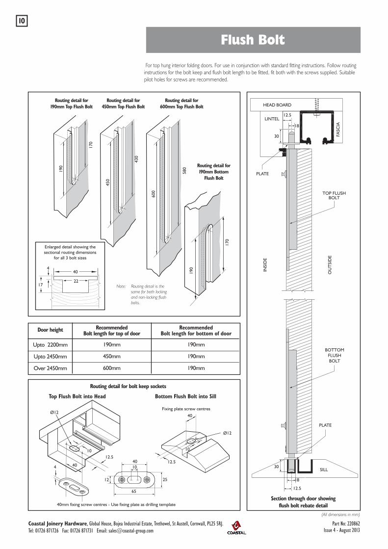
For top hung interior folding doors. For use in conjunction with standard fitting instructions. Follow routinginstructions for the bolt keep and flush bolt length to be fitted, fit both with the screws supplied. Suitablepilot holes for screws are recommended.
TOP FLUSHBOLT
BOTTOMFLUSHBOLT
SILL
(All dimensions in mm)
HEAD BOARD
LINTEL
FASC
IA
18
Enlarged detail showing thesectional routing dimensions
for all 3 bolt sizes
Note: Routing detail is the same for both locking and non-locking flush bolts.
Section through door showingflush bolt rebate detail
Routing detail for bolt keep sockets
Door height
Upto 2200mm
Upto 2450mm
Over 2450mm
RecommendedBolt length for top of door
190mm
450mm
600mm
RecommendedBolt length for bottom of door
190mm
190mm
190mm
Routing detail for190mm Top Flush Bolt
Routing detail for450mm Top Flush Bolt
Routing detail for600mm Top Flush Bolt
30
18
30
190
190
170
170
450
430
600
580
404
12.512.5
12.5
12.5
Ø12
Ø12
10 10
40
4010
25
65
12
40
22
4
17
Bottom Flush Bolt into SillTop Flush Bolt into Head
Fixing plate screw centres
Routing detail for190mm Bottom
Flush BoltPLATE
PLATE
40mm fixing screw centres - Use fixing plate as drilling template
OU
TSI
DE
INSI
DE
Flush Bolt10
Coastal Joinery Hardware, Global House, Bojea Industrial Estate, Trethowel, St Austell, Cornwall, PL25 5RJ.Tel: 01726 871726 Fax: 01726 871731 Email: [email protected]
Part No: 220862Issue 4 - August 2013