Embed Size (px)
Citation preview
Water managementTECHNICAL DESIGN MANUAL
Wavin Quickstream Siphonic Roof Drainage
(52.5) (H1)
Uniclass EPICJR12:L731/L71121/L2123 J3413:X721
CI/SfB
June 2015
1www.wavin.co.uk Email: [email protected] Wavin QuickStream TDM
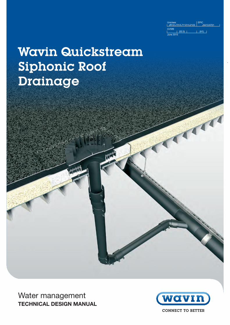
Contents QuickStream
1. Introduction 2-5
1.1 Rainwater Systems 21.2 Principles of Full-Bore Flow 31.3 System Components 31.4 Advantages and Disadvantages of a Siphonic System 41.5 Customer Benefits of Wavin’s QuickStream System 5
2. General Design Issues 6-10
2.1 Introduction 62.2 Roof and Gutter Types 6-82.3 Design Rainfall Capacity 92.4 Note on Emergency Drainage System 10
3. System Design 11-14
3.1 Introduction 113.2 Maximum Head Losses and System Balancing 113.3 Positive and Negative Pressures and Cavitation 123.4 Priming of The System 123.5 Minimum Flow Velocities 133.6 Branching into The Downpipe 14
4. Roof Outlets For The Primary Siphonic System 15-16
4.1 Number of Roof Outlets 154.2 Location of The Roof Outlets 154.3 Type of Roof Outlets 154.4 Insulation of Roof Outlets 16
4.5 Roof Outlet Constructions For Green Roofs and Parking Decks 164.6 Electrical Heating Elements 16
5. Emergency Overflow System 17-18
5.1 Introduction 175.2 Calculation of a Rectangular Overflow System 175.3 Calculation of a Piped Overflow System 185.4 Wavin QuickStream Siphonic Overflow System 185.5 Location of The Emergency Overflow 18
6. Pipe System Layout 19
6.1 General Considerations 196.2 Slope in Horizontal Pipe Systems 196.3 Drainage of Different Roof Areas 196.4 Thermal Condensation 196.5 Fire Precautions 196.6 Acoustic and Thermal Insulation 19
7. Fixing of The Pipe System 20
7.1 Fixing The Horizontal Collecting Pipe 20
8. Discharge to The Gravity Drainage System 21
8.1 Introduction 218.2 Maximum Velocities at The Discharge Point 228.3 Underground Pipe Work 22
9. Commissioning and Maintenance 23
9.1 Commissioning 239.2 Maintenance 23
10. Problem Solving / Technical Support 24
11. Specification of Siphonic Systems 25
11.1 Introduction 2511.2 System Specification and Design 2511.3 Installation 2511.4 Commissioning 2611.5 Maintenance 26
Technical Design ManualQuickStream
2 Wavin QuickStream TDM Customer Services: 0844 856 5152 Technical Advice: 0844 856 5165
1. Introduction
Wavin is one of the leading suppliers of siphonic roof drainage systems and has over 30 years experience in siphonic design and installation of siphonic systems. Although siphonic systemsare well adopted in most European countries, there is still a lack of clarity about which minimum requirements need to be fulfilledto guarantee the proper functioning of a siphonic system.
The aim of this handbook is to give a clear picture about the design and operation of the system, and the minimum requirements a siphonic system needs to comply with, to ensure that it will discharge the rainfall intensity it is designed for.
1.1 Rainwater Systems
Rainwater systemsThe purpose of rainwater systems is to collect and transport water from roofs. For residential houses the most commonly used system is a combination of rainwater gutters installed alongthe eaves which direct the flow into rainwater downpipes.
Wavin has a wide range of plastic gutter systems for houses, which are aesthetically as well as technically fit for purpose. For large roof areas however a system composed of roof outlets in combination with gravity or siphonic pipe systems is used.
Siphonic systems are usually preferred over gravity systems for roof areas of 500m2 and above. The larger the roof area and the higher the roof, the bigger the advantages of siphonic systems.
Rainwater, infiltration and attenuationSince rainwater collected from large roof areas usually is not polluted, it is recommendable (using Wavin infilltration units and pipes wrapped in geotextile) to infiltrate the rainwater or to transport the rainwater to open water rather than to discharge the water to a storm water or combined sewerage system.
In situations where rainwater cannot be infiltrated, attenuation systems are recommended to limit the peak flow in the drainagesystem. This can be realised by installing a buffer tank made of Wavin infiltration units packed up with an impermeable membrane. The least preferred option is a direct discharge into adrainage system. Ideally storm drains should be separated from foul water drains.
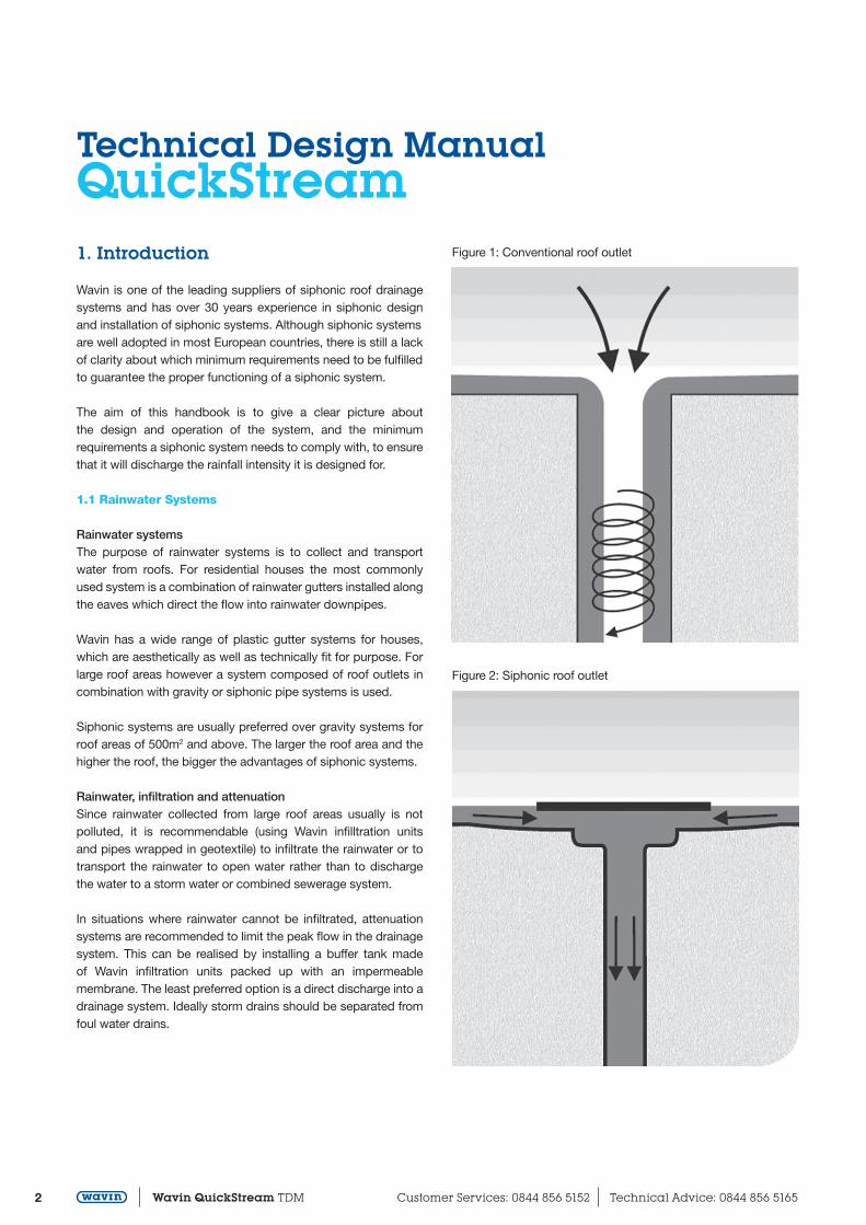
Figure 1: Conventional roof outlet
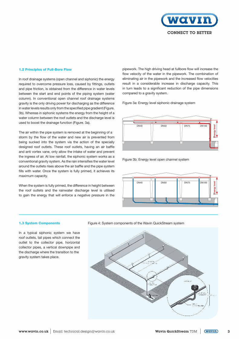
Figure 2: Siphonic roof outlet
3www.wavin.co.uk Email: [email protected] Wavin QuickStream TDM
1.2 Principles of Full-Bore Flow
In roof drainage systems (open channel and siphonic) the energyrequired to overcome pressure loss, caused by fittings, outlets and pipe friction, is obtained from the difference in water levels between the start and end points of the piping system (water column). In conventional open channel roof drainage systems gravity is the only driving power for discharging as the differencein water levels results only from the specified pipe gradient (Figure. 3b). Whereas in siphonic systems the energy from the height of a water column between the roof outlets and the discharge level is used to boost the drainage function (Figure. 3a).
The air within the pipe system is removed at the beginning of astorm by the flow of the water and new air is prevented from being sucked into the system via the action of the specially designed roof outlets. These roof outlets, having an air baffle and anti vortex vane, only allow the intake of water and prevent the ingress of air. At low rainfall, the siphonic system works as a conventional gravity system. As the rain intensifies the water level around the outlets rises above the air baffle and the pipe system fills with water. Once the system is fully primed, it achieves its maximum capacity.
When the system is fully primed, the difference in height betweenthe roof outlets and the rainwater discharge level is utilised to gain the energy that will enforce a negative pressure in the
pipework. The high driving head at fullbore flow will increase the flow velocity of the water in the pipework. The combination of eliminating air in the pipework and the increased flow velocities result in a considerable increase in discharge capacity. This in turn leads to a significant reduction of the pipe dimensions compared to a gravity system.
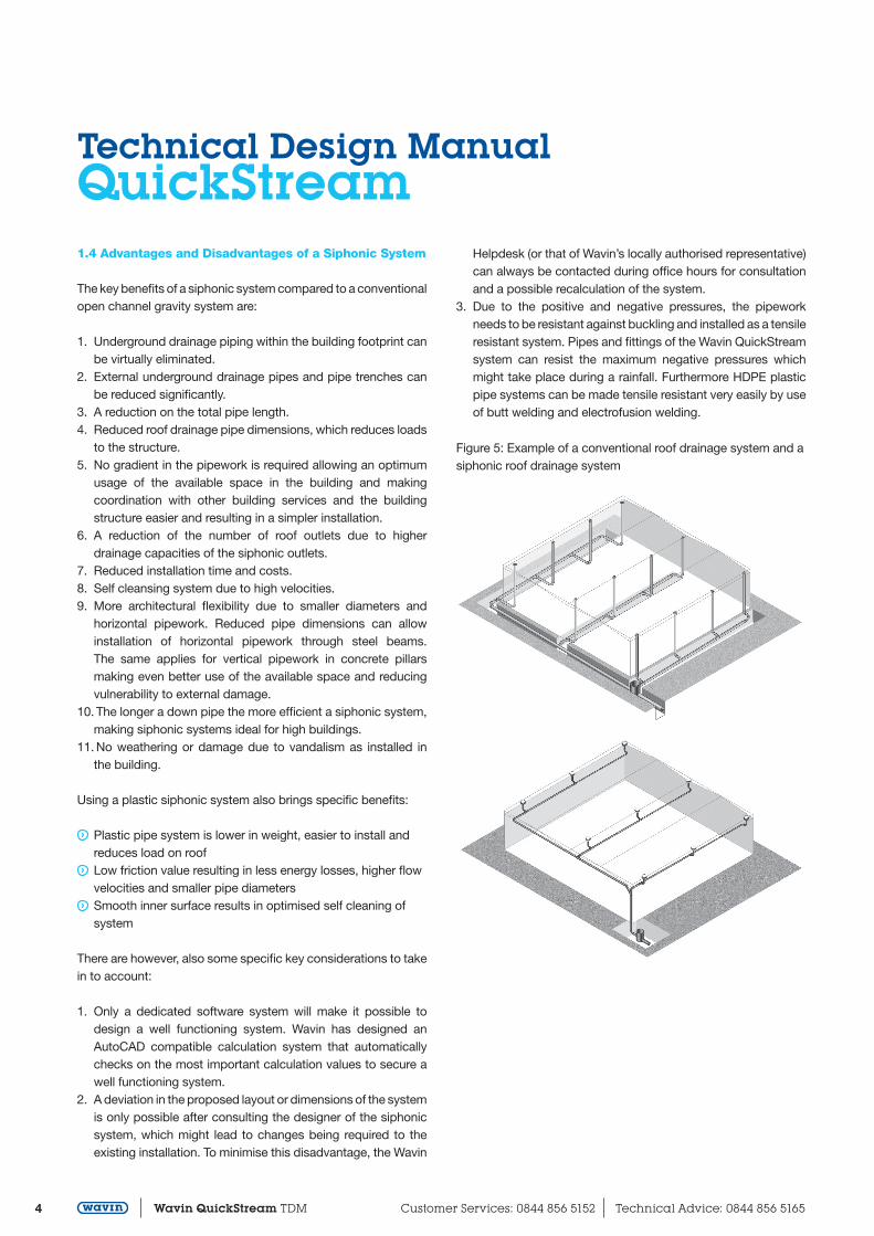
Figure 3a: Energy level siphonic drainage system
DN100DN75DN50DN40
Ene
rgy
leve
l
Figure 3b: Energy level open channel system
DN100DN75DN50DN40
Ene
rgy
leve
l
1.3 System Components
In a typical siphonic system we have roof outlets, tail pipes which connect the outlet to the collector pipe, horizontal collector pipes, a vertical downpipe and the discharge where the transition to thegravity system takes place.
Figure 4: System components of the Wavin QuickStream system
Technical Design ManualQuickStream
4 Wavin QuickStream TDM Customer Services: 0844 856 5152 Technical Advice: 0844 856 5165
1.4 Advantages and Disadvantages of a Siphonic System
The key benefits of a siphonic system compared to a conventionalopen channel gravity system are:
1. Underground drainage piping within the building footprint can be virtually eliminated.
2. External underground drainage pipes and pipe trenches can be reduced significantly.
3. A reduction on the total pipe length.4. Reduced roof drainage pipe dimensions, which reduces loads
to the structure.5. No gradient in the pipework is required allowing an optimum
usage of the available space in the building and making coordination with other building services and the building structure easier and resulting in a simpler installation.
6. A reduction of the number of roof outlets due to higher drainage capacities of the siphonic outlets.
7. Reduced installation time and costs.8. Self cleansing system due to high velocities.9. More architectural flexibility due to smaller diameters and
horizontal pipework. Reduced pipe dimensions can allow installation of horizontal pipework through steel beams. The same applies for vertical pipework in concrete pillars making even better use of the available space and reducing vulnerability to external damage.
10. The longer a down pipe the more efficient a siphonic system, making siphonic systems ideal for high buildings.
11. No weathering or damage due to vandalism as installed in the building.
Using a plastic siphonic system also brings specific benefits:
Plastic pipe system is lower in weight, easier to install and reduces load on roof
Low friction value resulting in less energy losses, higher flow velocities and smaller pipe diameters
Smooth inner surface results in optimised self cleaning of system
There are however, also some specific key considerations to takein to account:
1. Only a dedicated software system will make it possible to design a well functioning system. Wavin has designed an AutoCAD compatible calculation system that automatically checks on the most important calculation values to secure a well functioning system.
2. A deviation in the proposed layout or dimensions of the system is only possible after consulting the designer of the siphonic system, which might lead to changes being required to the existing installation. To minimise this disadvantage, the Wavin
Helpdesk (or that of Wavin’s locally authorised representative) can always be contacted during office hours for consultation and a possible recalculation of the system.
3. Due to the positive and negative pressures, the pipework needs to be resistant against buckling and installed as a tensile resistant system. Pipes and fittings of the Wavin QuickStream system can resist the maximum negative pressures which might take place during a rainfall. Furthermore HDPE plastic pipe systems can be made tensile resistant very easily by use of butt welding and electrofusion welding.
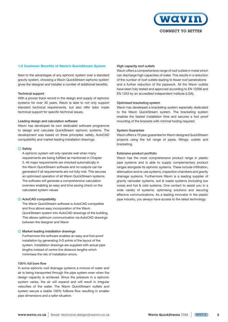
Figure 5: Example of a conventional roof drainage system and asiphonic roof drainage system
5www.wavin.co.uk Email: [email protected] Wavin QuickStream TDM
1.5 Customer Benefits of Wavin’s QuickStream System
Next to the advantages of any siphonic system over a standard gravity system, choosing a Wavin QuickStream siphonic systemgives the designer and installer a number of additional benefits:
Technical supportWith a proven track record in the design and supply of siphonic systems for over 30 years, Wavin is able to not only support standard technical requirements, but also offer tailor made technical support for specific technical issues.
Leading design and calculation softwareWavin has developed its own dedicated software programme to design and calculate QuickStream siphonic systems. The development was based on three principles: safety, AutoCAD compatibility and market leading installation drawings.
Safety A siphonic system will only operate well when many
requirements are being fulfilled as mentioned in Chapter 3. All major requirements are checked automatically in the Wavin QuickStream software and no outputs can be generated if all requirements are not fully met. This secures an optimised operation of all Wavin QuickStream systems. The software will generate a comprehensive calculation overview enabling an easy and time saving check on the calculated system values
AutoCAD compatibility The Wavin QuickStream software is AutoCAD compatible and thus allows easy incorporation of the Wavin
QuickStream system into AutoCAD drawings of the building. This allows optimum communication via AutoCAD drawings between the designer and Wavin
Market leading installation drawings Furthermore the software enables an easy and fool-proof installation by generating 3-D prints of the layout of the system. Installation drawings are supplied with actual pipe
lengths instead of centre line distance lengths which minimises the risk of installation errors.
100% full bore flowIn some siphonic roof drainage systems a mixture of water and air is being transported through the pipe system even when the design capacity is achieved. Since the pressure in a siphonic system varies, the air will expand and will result in irregular velocities of the water. The Wavin QuickStream outlets and system secure a stable 100% fullbore flow resulting in smaller pipe dimensions and a safer situation.
High capacity roof outletsWavin offers a comprehensive range of roof outlets in metal which can discharge high capacities of water. This results in a reduction of the number of roof outlets leading to fewer roof penetrationsand a further reduction of the pipework. All the Wavin outlets have been fully tested and approved according to EN 12056 and EN 1253 by an accredited independent institute (LGA).
Optimised bracketing systemWavin has developed a bracketing system especially dedicated to the Wavin QuickStream system. The bracketing system enables the fastest installation time and secures a fool proof mounting of the brackets with minimal tooling required.
System GuaranteeWavin offers a 10 year guarantee for Wavin designed QuickStreamprojects using the full range of pipes, fittings, outlets and bracketing.
Extensive product portfolioWavin has the most comprehensive product range in plastic pipe systems and is able to supply complementary product ranges alongside its siphonic systems. These include infiltration, attenuation and re-use systems, inspection chambers and gravitydrainage systems. Furthermore Wavin is a leading supplier of gravity rainwater systems, soil & waste systems (including low noise) and hot & cold systems. One contact to assist you in a wide variety of systems, optimising solutions and securing effective communications. As a leading innovator in the plastic pipe industry, you always have access to the latest technology.
Technical Design ManualQuickStream
6 Wavin QuickStream TDM Customer Services: 0844 856 5152 Technical Advice: 0844 856 5165
2. General Design Issues
2.1 Introduction
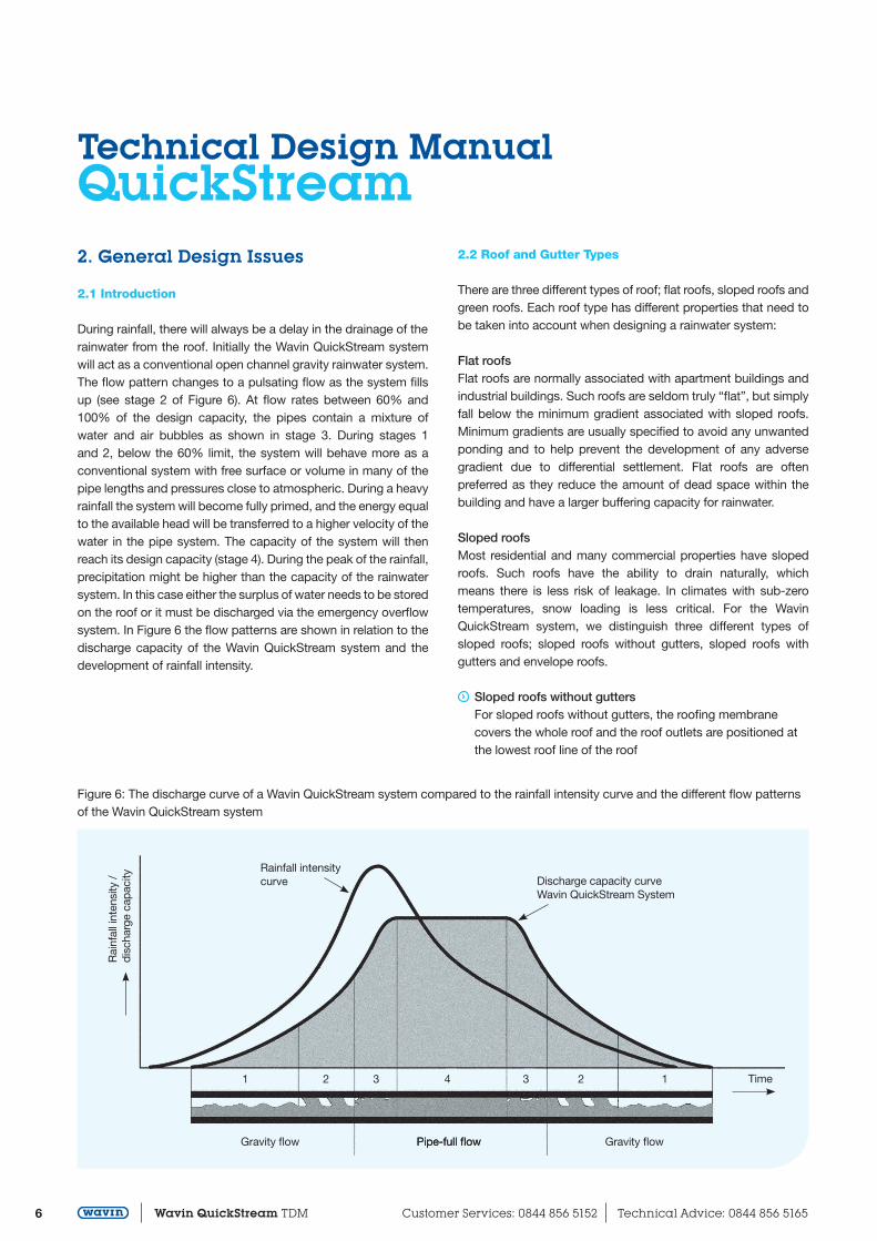
During rainfall, there will always be a delay in the drainage of therainwater from the roof. Initially the Wavin QuickStream system will act as a conventional open channel gravity rainwater system. The flow pattern changes to a pulsating flow as the system fills up (see stage 2 of Figure 6). At flow rates between 60% and 100% of the design capacity, the pipes contain a mixture of water and air bubbles as shown in stage 3. During stages 1 and 2, below the 60% limit, the system will behave more as a conventional system with free surface or volume in many of the pipe lengths and pressures close to atmospheric. During a heavy rainfall the system will become fully primed, and the energy equal to the available head will be transferred to a higher velocity of the water in the pipe system. The capacity of the system will then reach its design capacity (stage 4). During the peak of the rainfall, precipitation might be higher than the capacity of the rainwater system. In this case either the surplus of water needs to be stored on the roof or it must be discharged via the emergency overflow system. In Figure 6 the flow patterns are shown in relation to the discharge capacity of the Wavin QuickStream system and the development of rainfall intensity.
Figure 6: The discharge curve of a Wavin QuickStream system compared to the rainfall intensity curve and the different flow patterns of the Wavin QuickStream system
2.2 Roof and Gutter Types
There are three different types of roof; flat roofs, sloped roofs andgreen roofs. Each roof type has different properties that need to be taken into account when designing a rainwater system:
Flat roofsFlat roofs are normally associated with apartment buildings and industrial buildings. Such roofs are seldom truly “flat”, but simply fall below the minimum gradient associated with sloped roofs. Minimum gradients are usually specified to avoid any unwanted ponding and to help prevent the development of any adverse gradient due to differential settlement. Flat roofs are often preferred as they reduce the amount of dead space within the building and have a larger buffering capacity for rainwater.
Sloped roofsMost residential and many commercial properties have sloped roofs. Such roofs have the ability to drain naturally, which means there is less risk of leakage. In climates with sub-zero temperatures, snow loading is less critical. For the Wavin QuickStream system, we distinguish three different types of sloped roofs; sloped roofs without gutters, sloped roofs with gutters and envelope roofs.
Sloped roofs without gutters For sloped roofs without gutters, the roofing membrane
covers the whole roof and the roof outlets are positioned at the lowest roof line of the roof
Rainfall intensity curve Discharge capacity curve
Wavin QuickStream System
Time
Gravity flowGravity flow
1 12 23 34
Pipe-full flowPipe-full flow
Rai
nfal
l int
ensi
ty /
d
isch
arge
cap
acity
7www.wavin.co.uk Email: [email protected] Wavin QuickStream TDM
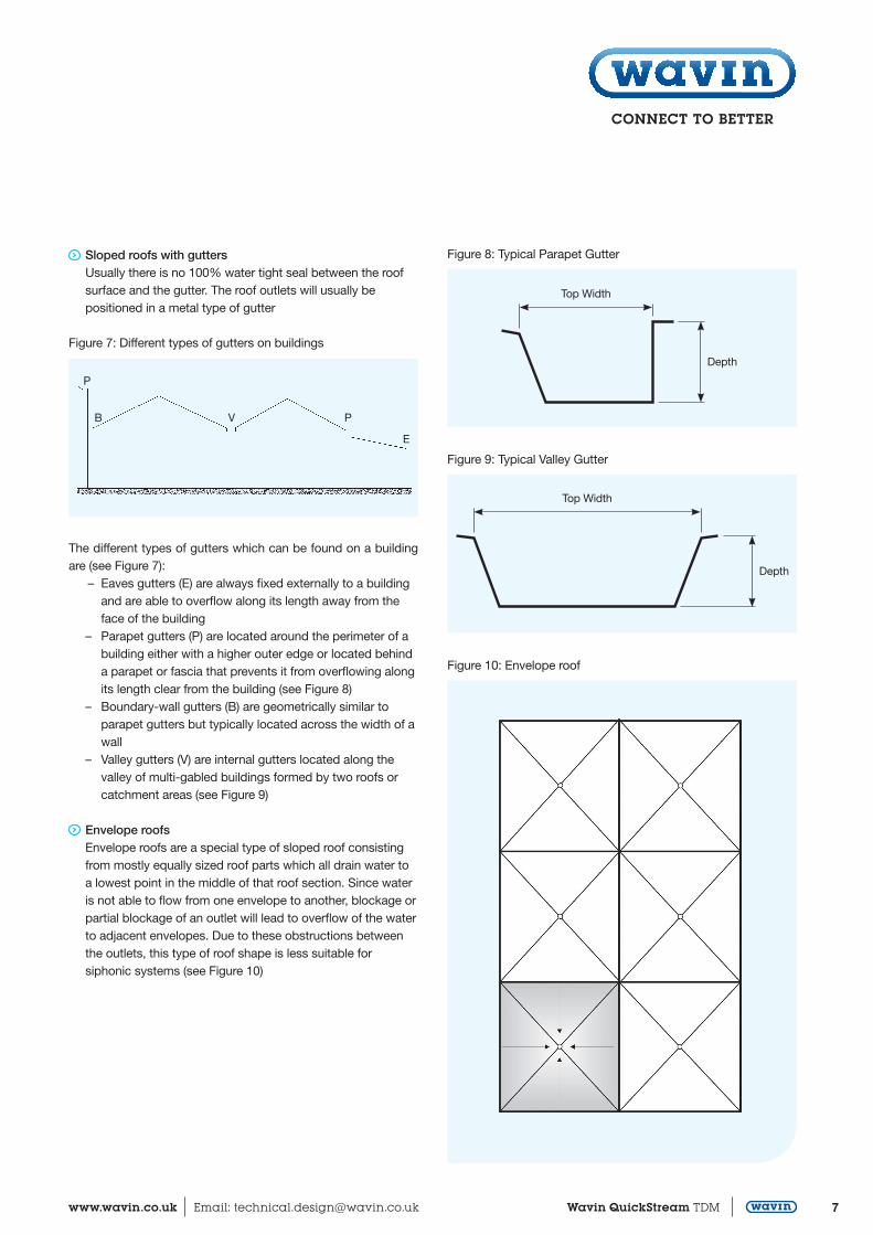
Sloped roofs with gutters Usually there is no 100% water tight seal between the roof
surface and the gutter. The roof outlets will usually be positioned in a metal type of gutter
Figure 7: Different types of gutters on buildings
Figure 8: Typical Parapet Gutter
Figure 9: Typical Valley Gutter
Figure 10: Envelope roof
P
B V P
E
Top Width
Depth
Top Width
Depth
The different types of gutters which can be found on a building are (see Figure 7): – Eaves gutters (E) are always fixed externally to a building and are able to overflow along its length away from the face of the building – Parapet gutters (P) are located around the perimeter of a building either with a higher outer edge or located behind
a parapet or fascia that prevents it from overflowing along its length clear from the building (see Figure 8)
– Boundary-wall gutters (B) are geometrically similar to parapet gutters but typically located across the width of a wall
– Valley gutters (V) are internal gutters located along the valley of multi-gabled buildings formed by two roofs or catchment areas (see Figure 9)
Envelope roofs Envelope roofs are a special type of sloped roof consisting from mostly equally sized roof parts which all drain water to a lowest point in the middle of that roof section. Since water is not able to flow from one envelope to another, blockage or partial blockage of an outlet will lead to overflow of the water to adjacent envelopes. Due to these obstructions between the outlets, this type of roof shape is less suitable for
siphonic systems (see Figure 10)
Technical Design ManualQuickStream
8 Wavin QuickStream TDM Customer Services: 0844 856 5152 Technical Advice: 0844 856 5165
Implications of the roof shape on the design of the roofdrainage systemDuring rainfall, a siphonic system works optimally when all roof outlets are discharging the amount of water they have been designed to discharge, or all are discharging an equal proportion of their designed capacity. In these situations the system will be well balanced. The amount of water flowing to roof outlets can however be disturbed by several elements:
bending of the roof (sagging), clogging of outlets, deviations from design (such as distances between outlets,
pipe layout and/or pipe diameters) and
wind effects
To minimise these disturbing factors it is important that there is always the possibility for “communication” between the roof outlets: when one outlet receives too much water, it should be possible for the water to flow to other outlets. Outlets which are connected to the same collector pipe must be at the same levelin the roof to provide communication. Obstacles between roof outlets should be avoided.
If wind influences the amount of water falling on different roofs, these roofs are not allowed to be connected to a single commondownpipe at the top of the building as the negative pressures could be too high.
Outlets in area A should not be connected to the same downpipeas outlets in area B. This is shown in Figure 14.
If a connection to one downpipe is desired, Wavin advises to connect the pipes discharging water from the roof surfaces just above floor level where the pressure in the pipe system is close to zero (see Figure 15).
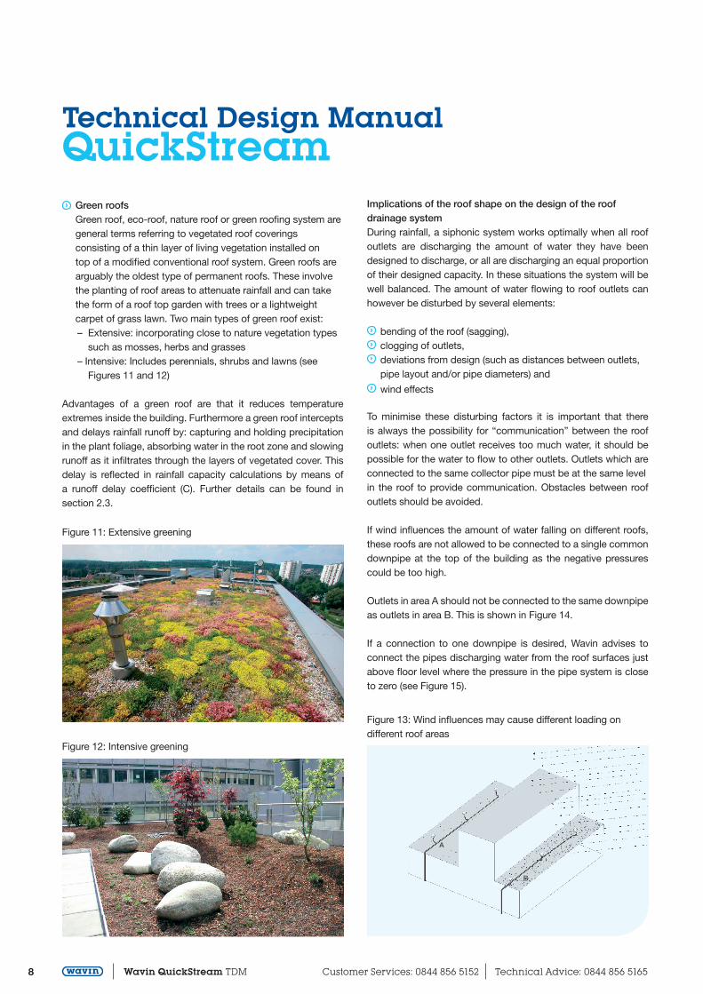
Green roofs Green roof, eco-roof, nature roof or green roofing system are general terms referring to vegetated roof coverings
consisting of a thin layer of living vegetation installed on top of a modified conventional roof system. Green roofs are arguably the oldest type of permanent roofs. These involve the planting of roof areas to attenuate rainfall and can take the form of a roof top garden with trees or a lightweight carpet of grass lawn. Two main types of green roof exist:
– Extensive: incorporating close to nature vegetation types such as mosses, herbs and grasses – Intensive: Includes perennials, shrubs and lawns (see Figures 11 and 12)
Advantages of a green roof are that it reduces temperature extremes inside the building. Furthermore a green roof interceptsand delays rainfall runoff by: capturing and holding precipitation in the plant foliage, absorbing water in the root zone and slowingrunoff as it infiltrates through the layers of vegetated cover. This delay is reflected in rainfall capacity calculations by means of a runoff delay coefficient (C). Further details can be found in section 2.3.
Figure 11: Extensive greening
Figure 12: Intensive greening
Figure 13: Wind influences may cause different loading ondifferent roof areas
A
B
9www.wavin.co.uk Email: [email protected] Wavin QuickStream TDM
To avoid an excessive rain load variation caused by wind, on roofareas with different slopes, Wavin advises not to connect slopedroof areas where the angle between the roof slopes is more than15 degrees (see Figure 16).
2.3 Design Rainfall Capacity
Design rainfall intensityIn most countries the design rainfall intensity is prescribed by national or local regulation and/or practice, e.g. 0.03 l/s/m2. If so, all calculations for determining a QuickStream system will be based on these values. If it is not prescribed the design rainfall intensity can be calculated depending on the duration of the rainfall (D, in minutes), the geographical location of the building and the return period of the rainfall event (T, in years). For this option Wavin advises to use a frequent return rate of a two minute storm to ensure a regular self cleaning of the pipe system. A thirdoption is to use the method provided in EN12056 part 3.
Wavin advises to always install an emergency overflow system on a flat roof and in non-eaves gutters. For the emergency overflow a simple opening in the roof rim or a siphonic system can be used. The capacity of the overflow system should be designed on the extra capacity resulting form the risk level as mentioned in EN 12056 or the capacity resulting from national and local regulations. In cases where no regulations exist, common practice should be followed.
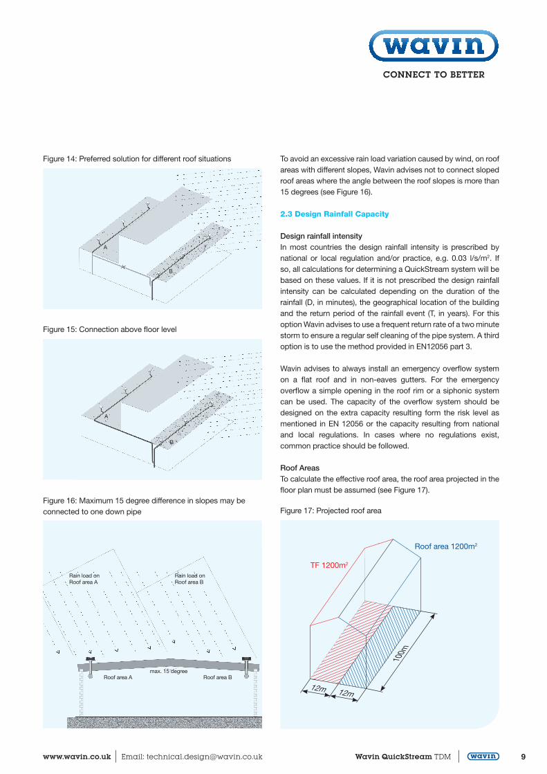
Roof AreasTo calculate the effective roof area, the roof area projected in thefloor plan must be assumed (see Figure 17).
A
B
Figure 14: Preferred solution for different roof situations
Figure 15: Connection above floor level
A
B
Figure 16: Maximum 15 degree difference in slopes may be connected to one down pipe
Rain load on Roof area A
Rain load on Roof area B
Roof area A Roof area Bmax. 15 degree
Figure 17: Projected roof area
TF 1200m2
Roof area 1200m2
100m
12m12m
Technical Design ManualQuickStream
10 Wavin QuickStream TDM Customer Services: 0844 856 5152 Technical Advice: 0844 856 5165
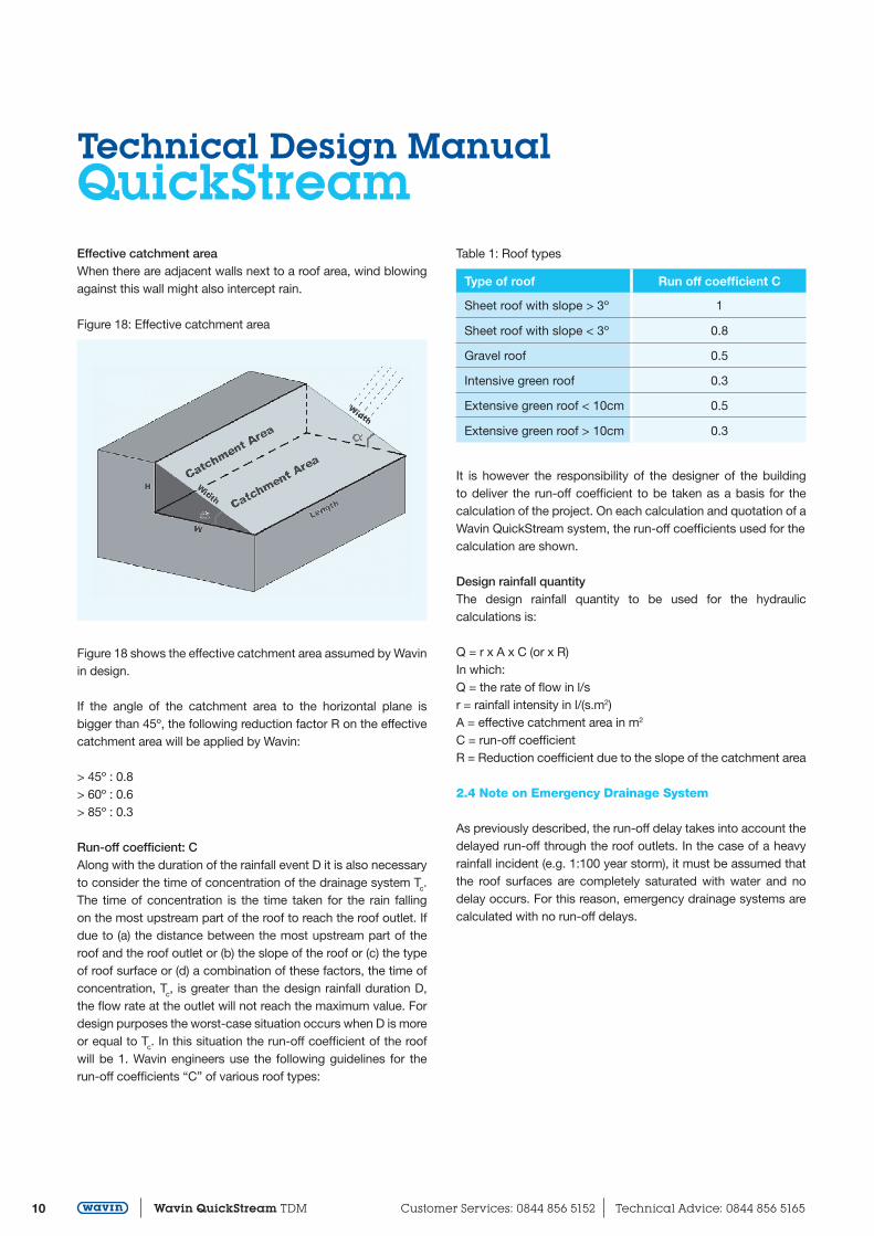
Effective catchment areaWhen there are adjacent walls next to a roof area, wind blowing against this wall might also intercept rain.
Figure 18: Effective catchment area
Figure 18 shows the effective catchment area assumed by Wavin in design.
If the angle of the catchment area to the horizontal plane is bigger than 45º, the following reduction factor R on the effective catchment area will be applied by Wavin:
> 45º : 0.8> 60º : 0.6> 85º : 0.3
Run-off coefficient: CAlong with the duration of the rainfall event D it is also necessaryto consider the time of concentration of the drainage system Tc. The time of concentration is the time taken for the rain falling on the most upstream part of the roof to reach the roof outlet. If due to (a) the distance between the most upstream part of the roof and the roof outlet or (b) the slope of the roof or (c) the type of roof surface or (d) a combination of these factors, the time of concentration, Tc, is greater than the design rainfall duration D, the flow rate at the outlet will not reach the maximum value. For design purposes the worst-case situation occurs when D is moreor equal to Tc. In this situation the run-off coefficient of the roof will be 1. Wavin engineers use the following guidelines for the run-off coefficients “C” of various roof types:
Table 1: Roof types
Type of roof Run off coefficient C
Sheet roof with slope > 3º 1
Sheet roof with slope < 3º 0.8
Gravel roof 0.5
Intensive green roof 0.3
Extensive green roof < 10cm 0.5
Extensive green roof > 10cm 0.3
It is however the responsibility of the designer of the building to deliver the run-off coefficient to be taken as a basis for the calculation of the project. On each calculation and quotation of aWavin QuickStream system, the run-off coefficients used for thecalculation are shown.
Design rainfall quantityThe design rainfall quantity to be used for the hydraulic calculations is:
Q = r x A x C (or x R)In which:Q = the rate of flow in l/sr = rainfall intensity in l/(s.m2)A = effective catchment area in m2
C = run-off coefficientR = Reduction coefficient due to the slope of the catchment area
2.4 Note on Emergency Drainage System
As previously described, the run-off delay takes into account thedelayed run-off through the roof outlets. In the case of a heavy rainfall incident (e.g. 1:100 year storm), it must be assumed that the roof surfaces are completely saturated with water and no delay occurs. For this reason, emergency drainage systems are calculated with no run-off delays.
11www.wavin.co.uk Email: [email protected] Wavin QuickStream TDM
3. System Design
3.1 Introduction
The design of the Wavin QuickStream siphonic system incorporates a calculation of the rainfall load, number and location of the roof outlets in addition to an optimised layout and calculation of the Wavin QuickStream pipe system. Wavin uses a state of the art, AutoCAD compatible software programme to assist in making an optimised and reliable system design, which automatically makes the most important checks on the system imbalance between the roof outlets, maximum negative pressure, minimum flow velocities in the system, maximum flow velocities at discharge and the priming of the system. Only if all checks have been concluded positively, can outputs be printed from the software.
Wavin is the only siphonic system supplier who has incorporatedcompulsory checks on all above mentioned system values, ensuring that the systems designed by Wavin are always fit for purpose. On request Wavin will supply a summary of all calculated values of the Wavin QuickStream system for the designer so a check can be made that all minimum requirements are being fulfilled.
3.2 Maximum Head Losses and System Balancing
The available head for the design of a siphonic system is the vertical distance between the roof outlets to the cover level of thechamber to which the siphonic system discharges, or the level ofthe siphon break in the vertical downpipe. A siphon break is an increase in the diameter in the downpipe or in a horizontal pipe inflow direction.
For all flow paths of each roof outlet to the discharge point the dimensioning of the pipelines must be determined in such a way that the total friction losses in the pipes and fittings at the design rate match as closely as possible but do not exceed the available head. The maximum difference in calculated friction losses of all flow paths of each outlet to the discharge shall not be greater than 1 meter water pressure. If this occurs, the capacity of the different outlets will differ too much. This will result in water being drained from certain roof parts more quickly than other parts and consequently results in suction of air into these roof outlets and thus a breakage of the siphonic action. This will result in a reduction of the capacity of the whole system.
In practice, balancing is achieved by reducing the diameter of thetailpipes closest to the downpipe, and increasing the diameter ofthose further away.
Systems designed by Wavin always comply with this criterion for the maximum difference in head loss between all the outlets.
This ensures good operation and is automatically checked by theWavin QuickStream design software programme (See Table 2). All outputs from the software are blocked if this requirement is not being fulfilled.
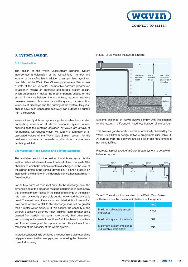
Figure 19: Estimating the available height
Manhole
Theoretical available height
Actual available height
Max. water level when sewer system is blocked
Figure 20: Typical layout of a QuickStream system to get a wellbalanced system
75mm 63mm 50mm 40mm
75mm 75mm 90mm
110mm
Table 2: The calculation overview of the Wavin QuickStreamsoftware shows the maximum imbalance of the system
(mm)
Maximum allowable systemimbalance:
1000
Maximum system imbalance: 684
Maximum system imbalance< allowable imbalance:
OK
Technical Design ManualQuickStream
12 Wavin QuickStream TDM Customer Services: 0844 856 5152 Technical Advice: 0844 856 5165
3.3 Positive and Negative Pressures and Cavitation
A fully primed system acts with negative and positive pressures in the pipework. Most of the system operates (at a negative pressure) at full bore flow. At the roof outlets and discharge point the pressure is atmospheric pressure. In most projects the highest negative pressure can be found at the top of the vertical downpipe. When the Wavin QuickStream system is extended horizontally outside the building and is connected to a manhole or is flowing into open water, positive pressures can also be found in that part of the pipe system. A schematic overview of the pressures in the pipe system can be found in Figure 21.
Negative pressures have a more severe effect than equivalent positive pressures on the strength of the pipes because pipe walls have a tendency to deform and buckle asymmetrically under negative pressures. It is therefore important to always use the SDR/pressure rating of pipework specified in the Wavin QuickStream design.
In tall buildings which exceed approximately 12 metres in height,it is possible for negative pressures in the pipes to approach the vapour pressure of water. When this occurs, the water will effectively boil and form cavities filled with water vapour. This process is called cavitation and can result in serious turbulence and pressure fluctuations in the pipe work. When vapour cavitiescollapse, they can generate extremely high impact pressures that are capable of causing serious damage to the strongest of materials including steel. At 20ºC and at sea level, cavitation occurs in water at a negative pressure of 0.97 bars.
All Wavin QuickStream systems are designed not to exceed a negative pressure of 0.9 bars which offers a 10% safety factor against cavitation occuring (e.g. Table. 3). If the location of the building is below sea level or if the expected rainwater temperature requires a lower safety pressure, the software will automatically adapt the maximum allowable negative pressure. The level of under pressure can be influenced by choosing alternative pipe diameters. The Wavin QuickStream software programme will automatically check the maximum allowable negative pressure in the system and block all outputs if the valuedoes not meet the requirements. All Wavin pipes and fittings used for the Wavin QuickStream pipe system are designed to resist the maximum negative pressures at which cavitation takes place and can thus resist all negative pressures which might take place during rainfall.
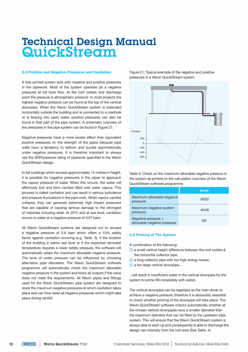
Figure 21: Typical example of the negative and positive pressures in a Wavin QuickStream system
P (mbar)
-200
0
-200
-400
-600
Table 3: Check on the maximum allowable negative pressure in the system as printed on the calculation overview of the Wavin QuickStream software programme
(mm)
Maximum allowable negativepressure:
-9000
Maximum negative systempressure:
-6448
Negative pressure <allowable negative pressure:
OK
3.4 Priming of The System
A combination of the following: a small vertical height difference between the roof outlets &
the horizontal collector pipe, a long collector pipe with too high energy losses, a too large vertical downpipe...
...will result in insufficient water in the vertical downpipe for thesystem to prime (fill completely with water).
The vertical downpipe can be regarded as the main driver toachieve a negative pressure, therefore it is absolutely essentialto check whether priming of the downpipe will take place. TheWavin QuickStream software checks automatically whether allthe chosen vertical downpipes have a smaller diameter thanthe maximum diameter that can be filled by the upstream pipesystem. This will ensure that the Wavin QuickStream system isalways able to start-up and consequently is able to discharge thedesign rain intensity from the roof area (See Table. 4).
13www.wavin.co.uk Email: [email protected] Wavin QuickStream TDM
3.5 Minimum Flow Velocities
The system needs to be checked on minimum velocities at thedesign rate in the vertical and horizontal pipes. The velocity inhorizontal pipes should be greater than 0.7m/s (and 0.5m/s forsmall pipe diameters) in order to secure the removal of air duringpriming and in order to provide a suitable degree of self-cleansingto prevent the build-up of sediment or other debris in thehorizontal pipelines. Self-cleansing will start during the primingphase. The water-air mixture creates sufficient turbulence toloosen any deposits.
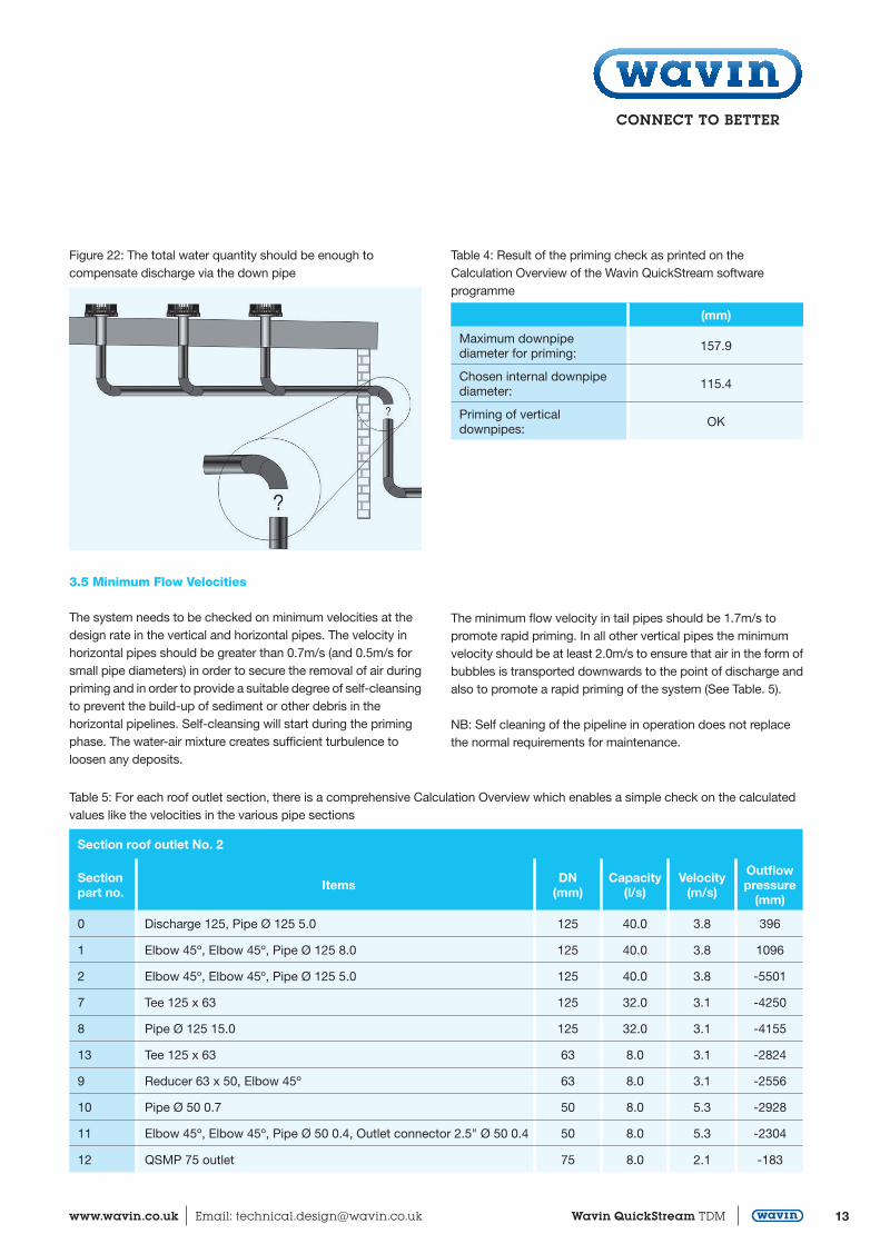
Figure 22: The total water quantity should be enough tocompensate discharge via the down pipe
The minimum flow velocity in tail pipes should be 1.7m/s topromote rapid priming. In all other vertical pipes the minimumvelocity should be at least 2.0m/s to ensure that air in the form ofbubbles is transported downwards to the point of discharge andalso to promote a rapid priming of the system (See Table. 5).
NB: Self cleaning of the pipeline in operation does not replacethe normal requirements for maintenance.
Table 4: Result of the priming check as printed on the Calculation Overview of the Wavin QuickStream software programme
(mm)
Maximum downpipediameter for priming:
157.9
Chosen internal downpipediameter:
115.4
Priming of verticaldownpipes:
OK
Table 5: For each roof outlet section, there is a comprehensive Calculation Overview which enables a simple check on the calculated values like the velocities in the various pipe sections
Section roof outlet No. 2
Sectionpart no. Items DN
(mm)Capacity
(l/s)Velocity
(m/s)
Outflowpressure
(mm)
0 Discharge 125, Pipe Ø 125 5.0 125 40.0 3.8 396
1 Elbow 45º, Elbow 45º, Pipe Ø 125 8.0 125 40.0 3.8 1096
2 Elbow 45º, Elbow 45º, Pipe Ø 125 5.0 125 40.0 3.8 -5501
7 Tee 125 x 63 125 32.0 3.1 -4250
8 Pipe Ø 125 15.0 125 32.0 3.1 -4155
13 Tee 125 x 63 63 8.0 3.1 -2824
9 Reducer 63 x 50, Elbow 45º 63 8.0 3.1 -2556
10 Pipe Ø 50 0.7 50 8.0 5.3 -2928
11 Elbow 45º, Elbow 45º, Pipe Ø 50 0.4, Outlet connector 2.5" Ø 50 0.4 50 8.0 5.3 -2304
12 QSMP 75 outlet 75 8.0 2.1 -183
Technical Design ManualQuickStream
14 Wavin QuickStream TDM Customer Services: 0844 856 5152 Technical Advice: 0844 856 5165
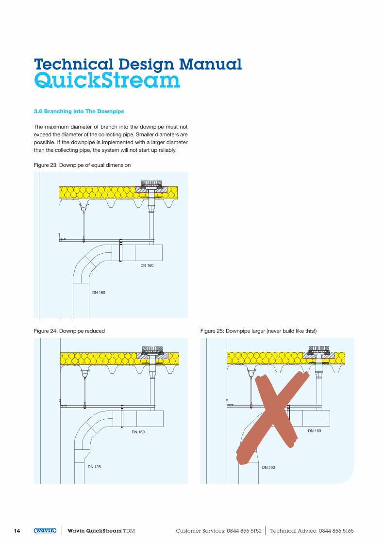
3.6 Branching into The Downpipe
The maximum diameter of branch into the downpipe must not exceed the diameter of the collecting pipe. Smaller diameters arepossible. If the downpipe is implemented with a larger diameter than the collecting pipe, the system will not start up reliably.
Figure 23: Downpipe of equal dimension
Figure 24: Downpipe reduced
DN 160
DN 160
DN 160
DN 125
Figure 25: Downpipe larger (never build like this!)
DN 1607DN 200
15www.wavin.co.uk Email: [email protected] Wavin QuickStream TDM
4. Roof Outlets For The Primary Siphonic System
4.1 Number of Roof Outlets
The number and locations of roof outlets can be determined once the drainage capacity is calculated, taking into account the rain intensity, run-off factor and catchment areas.
Based on the input data from the architect, Wavin experts will use computer modelling to make a detailed layout proposal and hydraulic calculations. The number of roof outlets will be determined by a combination of the drainage capacity of the roof area, the drainage capacity of the roof outlets, the distance between the roof outlets and the required maximum water level at the roof outlets.
The maximum intermediate distance of the roof outlets is 30 metres for the standard or primary siphonic system. If a siphonicsystem is also being used for the emergency or secondary system, Wavin will also apply a maximum intermediate distance of 30 metres.
The Wavin design will supply the water-level next to the Wavin QuickStream roof outlets. However, the Designer of the building is responsible for the water-load calculation on the roof bearing in mind the water-level of the primary as well as of the secondary or emergency overflow system.
4.2 Location of The Roof Outlets
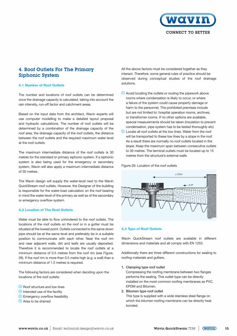
Water must be able to flow unhindered to the roof outlets. The locations of the roof outlets on the roof or in a gutter must be situated at the lowest point. Outlets connected to the same downpipe should be at the same level and preferably be in a suitable position to communicate with each other. Near the roof rim and near adjacent walls, dirt and leafs are usually deposited. Therefore it is recommended to locate the roof outlets at a minimum distance of 0.5 metres from the roof rim (see Figure. 26). If the roof rim is more than 0.5 metre high (e.g. a wall) than a minimum distance of 1.5 metres is required.
The following factors are considered when deciding upon thelocations of the roof outlets:
Roof structure and low lines Intended use of the facility Emergency overflow feasibility Area to be drained
Figure 26: Location of the roof outlets
All the above factors must be considered together as theyinteract. Therefore, some general rules of practice should beobserved during conceptual studies of the roof drainage solutions.
Avoid locating the outlets or routing the pipework above rooms where condensation is likely to occur, or where
a failure of the system could cause property damage or harm to the personnel. The prohibited premises include but are not limited to: hospital operation rooms, archives, or transformer rooms. If no other options are available, special measurements should be taken (insulation to prevent condensation, pipe system has to be tested thoroughly etc)
Locate all roof outlets at the low lines. Water from the roof will be transported to these low lines by a slope in the roof. As a result there are normally no roof outlets located in the slope. Keep the maximum span between consecutive outlets to 30 metres. The terminal outlets must be located up to 15 metres from the structure’s external walls
≥ 0.5m
0-3º
4.3 Type of Roof Outlets
Wavin QuickStream roof outlets are available in different dimensions and materials and all comply with EN 1253.
Additionally there are three different constructions for sealing to roofing materials and gutters.
1. Clamping type roof outlet Compressing the roofing membrane between two flanges performs the sealing. This outlet type can be directly installed on the most common roofing membranes as PVC, EPDM and Bitumen.
2. Bitumen type roof outlet This type is supplied with a wide stainless steel flange on which the bitumen roofing membrane can be directly heat bonded.
Technical Design ManualQuickStream
16 Wavin QuickStream TDM Customer Services: 0844 856 5152 Technical Advice: 0844 856 5165
3. Gutter type roof outlet These outlets are designed for installation in gutters. Sealing is performed by EPDM gaskets, with both surfaces of the gutter compressed between the clamping ring and the outlet part. Upon request a gutter type can also be supplied with a metal sheet of the same material as the gutter, so that the outlet can be welded/ soldered into the gutter. Take into account that the gutter outlets will be about 3mm above the surface of the gutter. This means a residual amount of water remains after rainfall has ended. If this is to be avoided, the gutter has to be deformed in the area of the outlet to let the outlet sink about 3mm.
4.4 Insulation of Roof Outlets
In order to prevent leakages inside the building due to condensation, roof outlets must be insulated. If there is a “cold” roof with a ventilated space under the roof, the pipe work in thatspace must also be insulated. Wavin can supply insulation blockswith the roof outlets.
As an indication, a plastic pipe installed in an area at room temperature, will reach an outside temperature that is approximate 3º to 5º higher than the inside water temperature. Note that a “cold” rainfall during any season might induce condensation.
4.5 Roof Outlet Constructions For Green Roofs and Parking Decks
Drainage systems from roof gardens and parking decks should enable inspection and access to the outlet and in the case of green roofs, shall incorporate means of excluding soil and debrisfrom entering the roof drainage system.
4.6 Electrical Heating Elements
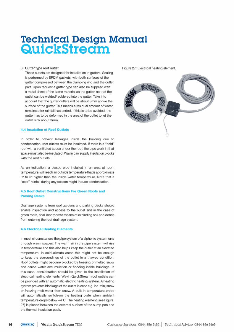
In most circumstances the pipe system of a siphonic system runsthrough warm spaces. The warm air in the pipe system will rise in temperature and this also helps keep the outlet at an elevatedtemperature. In cold climate areas this might not be enough to keep the surroundings of the outlet in a thawed condition. Roof outlets might become blocked by freezing of melted snow and cause water accumulation or flooding inside buildings. In this case, consideration should be given to the installation of electrical heating elements. Wavin QuickStream roof outlets can be provided with an automatic electric heating system. A heatingsystem prevents blockage of the outlet in case e.g. ice-rain, snowor freezing melt water from snow. A built in temperature probe will automatically switch-on the heating plate when ambient temperature drops below +4ºC. The heating element (see Figure.27) is placed between the external surface of the sump pan and the thermal insulation pack.
Figure 27: Electrical heating element.
17www.wavin.co.uk Email: [email protected] Wavin QuickStream TDM
5. Emergency Overflow System
5.1 Introduction
It is possible that a primary siphonic system does not function well, due to clogged outlets or a disturbed sewer system. Wavintherefore always advises installing an emergency overflow system, especially on flat roofs with parapets and in non-eaves gutters in order to reduce the risk of structural overloading or over-spilling of rainwater into a building. With eaves gutters and flat roofs with a low roof rim where these risks are not present, no additional safety system is required. Overflows may be used for different purposes, either singly or in combination:
To provide a warning that one or more roof outlets have become wholly or partially blocked by leaves or other dirt
and that maintenance is necessary; To cater for rare storm events so that the main rainwater
system can be sized more economically for storms that occur more frequently;
To increase the security of flat roofs and non eaves gutter systems;
To drain water from the roof if the primary system is not functioning correctly;
To drain water from the roof in the event that the water cannot be discharged for what ever reason (sewer system is blocked or full of water and no emergency relief chamber has been installed, the holes in the grating of the emergency
relief chamber can not cope with the discharge capacity of the siphonic system, etc)
Under normal conditions, an emergency overflow system shouldonly discharge water when rainfall exceeds the design rainfall. Operation of the Emergency Overflow system thus should be noticed by the building owners and the cause should be examined. There should be no transport to an underground pipe system unless a Wavin QuickStream warning system has been installed.
Locating a square orifice or setting a pipe culvert at the roof parapet is the simplest solution. If it is not feasible to provide a weir overflow, due to technical reasons, a separate siphonic system can be installed in order to avoid excessive water accumulation.
Figure 28: Water accumulation may cause bending of the roof
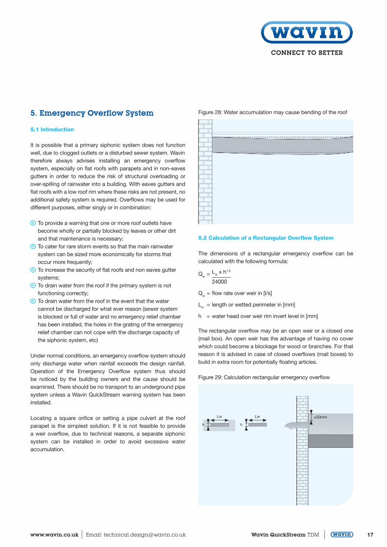
5.2 Calculation of a Rectangular Overflow System
The dimensions of a rectangular emergency overflow can be calculated with the following formula:
Qw = Lw x h1.5
24000
Qw = flow rate over weir in [l/s]
Lw = length or wetted perimeter in [mm]
h = water head over weir rim invert level in [mm]
The rectangular overflow may be an open weir or a closed one (mail box). An open weir has the advantage of having no cover which could become a blockage for wood or branches. For that reason it is advised in case of closed overflows (mail boxes) to build in extra room for potentially floating articles.
Figure 29: Calculation rectangular emergency overflow
h h
Lw Lw ±50mm
Technical Design ManualQuickStream
18 Wavin QuickStream TDM Customer Services: 0844 856 5152 Technical Advice: 0844 856 5165
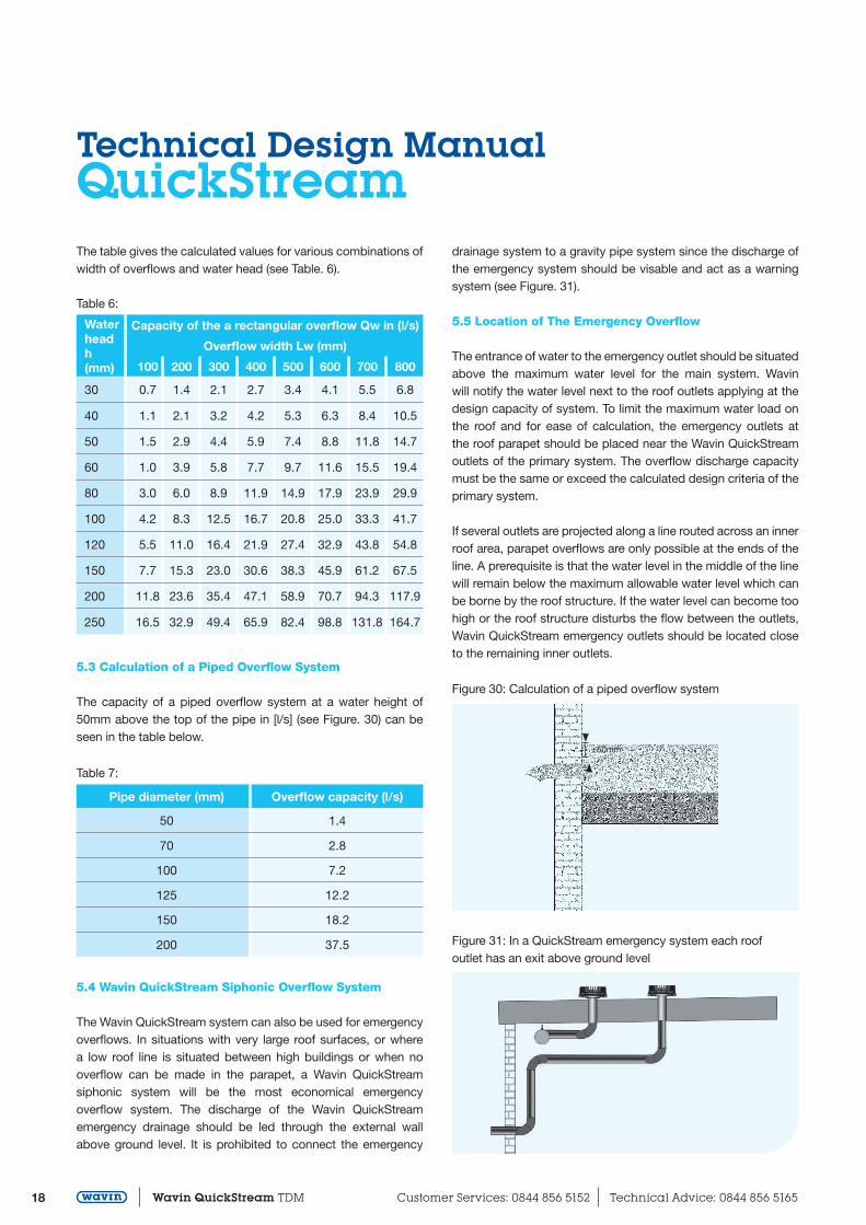
Table 6:
Waterheadh (mm)
Capacity of the a rectangular overflow Qw in (l/s)
Overflow width Lw (mm)
100 200 300 400 500 600 700 800
30 0.7 1.4 2.1 2.7 3.4 4.1 5.5 6.8
40 1.1 2.1 3.2 4.2 5.3 6.3 8.4 10.5
50 1.5 2.9 4.4 5.9 7.4 8.8 11.8 14.7
60 1.0 3.9 5.8 7.7 9.7 11.6 15.5 19.4
80 3.0 6.0 8.9 11.9 14.9 17.9 23.9 29.9
100 4.2 8.3 12.5 16.7 20.8 25.0 33.3 41.7
120 5.5 11.0 16.4 21.9 27.4 32.9 43.8 54.8
150 7.7 15.3 23.0 30.6 38.3 45.9 61.2 67.5
200 11.8 23.6 35.4 47.1 58.9 70.7 94.3 117.9
250 16.5 32.9 49.4 65.9 82.4 98.8 131.8 164.7
Table 7:
Pipe diameter (mm) Overflow capacity (l/s)
50 1.4
70 2.8
100 7.2
125 12.2
150 18.2
200 37.5
The table gives the calculated values for various combinations ofwidth of overflows and water head (see Table. 6).
5.3 Calculation of a Piped Overflow System
The capacity of a piped overflow system at a water height of 50mm above the top of the pipe in [l/s] (see Figure. 30) can be seen in the table below.
5.4 Wavin QuickStream Siphonic Overflow System
The Wavin QuickStream system can also be used for emergencyoverflows. In situations with very large roof surfaces, or where a low roof line is situated between high buildings or when no overflow can be made in the parapet, a Wavin QuickStream siphonic system will be the most economical emergency overflow system. The discharge of the Wavin QuickStream emergency drainage should be led through the external wall above ground level. It is prohibited to connect the emergency
drainage system to a gravity pipe system since the discharge of the emergency system should be visable and act as a warning system (see Figure. 31).
5.5 Location of The Emergency Overflow
The entrance of water to the emergency outlet should be situatedabove the maximum water level for the main system. Wavin will notify the water level next to the roof outlets applying at the design capacity of system. To limit the maximum water load on the roof and for ease of calculation, the emergency outlets at the roof parapet should be placed near the Wavin QuickStream outlets of the primary system. The overflow discharge capacity must be the same or exceed the calculated design criteria of theprimary system.
If several outlets are projected along a line routed across an innerroof area, parapet overflows are only possible at the ends of the line. A prerequisite is that the water level in the middle of the linewill remain below the maximum allowable water level which can be borne by the roof structure. If the water level can become toohigh or the roof structure disturbs the flow between the outlets, Wavin QuickStream emergency outlets should be located close to the remaining inner outlets.
Figure 30: Calculation of a piped overflow system
Figure 31: In a QuickStream emergency system each roofoutlet has an exit above ground level
±50mm
19www.wavin.co.uk Email: [email protected] Wavin QuickStream TDM
6. Pipe System Layout
6.1 General Considerations
Once all information about rainfall intensity, run-off coefficient and risk factors has been used to calculate the number of roof outlets, the layout of all pipe work can be made. For this, it is of utmost importance that the latest construction drawings of the building are made available to the Wavin design team. The designer of the building should indicate which locations could be used for installing the drainage systems. Of importance is the location and type of roof beams and columns. Also the preferred location and type of discharge point should be indicated. Based on this information, Wavin experts will make a proposal in the form of 3D drawings as well the results of hydraulic calculations.
Construction drawings in digital format, preferably AutoCAD will provide the most efficient design process.
Once all parties accept Wavin’s proposal, the installer is obliged to follow the design. Eventual changes in the design must alwaysbe discussed and agreed upon by all parties involved. This will ensure that the installed system will meet all the design and siphonic functioning requirements. If this rule is not strictly followed Wavin cannot accept any claims in relation to the operation of the system or the design criteria.
6.2 Slope in Horizontal Pipe Systems
Wavin QuickStream should be installed without any gradient. Negative gradients must be prevented because of possible depositing of accumulated dirt and for reasons of poor priming of the system.
Sagging of pipework in between brackets should also be kept to a minimum. A positive gradient has no negative influence on thefunctioning of the system.
6.3 Drainage of Different Roof Areas
Siphonic systems are only capable to discharge their design capacity when the whole system is fully primed. A strong differentiation in slopes of roof areas or walls next to roof areas which might intercept rain or increase the rainfall load considerably due to a variation in wind directions cannot guarantee an equal distribution of the rain on all roof areas. Furthermore different run-off coefficients of roof areas will also lead to not-equal priming of the system. Consequently roof areas with different run-off coefficients must not be connected to the same downpipe.
In these cases there are various options which guarantee the priming of the pipe system. The safest solution is to connect each
roof area to a different downpipe. Another option is to design an extra parallel downpipe for a roof area on which the rainfall load might differ from other areas. These two downpipes can be connected just above ground level where the pressure in thesystem is close to zero.
As stipulated above, in all cases Wavin’s design proposals shouldbe accurately followed in order to prevent imbalance in the system, which could lead to unwanted ingestion of air, resulting in a loss of drainage capacity during heavy rainfall (the design rain intensity).
6.4 Thermal Condensation
In humid environments there can be a need to insulate the pipe system to prevent condensation and subsequent water dripping.Condensation can happen when the relative humidity is above 40%. Commonly the temperature in the top of buildings is rather high.
To prevent condensation on the pipe surface, it is necessary to use sufficient insulation thickness and a vapour sealed foil on theoutside. The thickness of the insulation sheet depends on the ambient temperature, the humidity and of course the medium temperature. Be aware that a high ambient temperature is more critical for condensation than a low ambient temperature. A risk assessment by the designer will reveal the need for thermal insulation. For most situations, a 15mm thick insulation sheet canbe taken as a guideline.
6.5 Fire Precautions
If local safety regulations or project design specifications requiremeasures to prevent fires spreading to adjacent rooms or floors,fire collars must be installed.
In the case of direct heat the material in the fire collar will expandand will completely close the floor or wall passage.
6.6 Acoustic and Thermal Insulation
Like any rainwater system, siphonic roof drainage systems generate noise when transporting rainwater. In sensitive areas within buildings such as offices, concert halls, courthouses and hospitals where noise should be kept to a minimum level, it is recommended to wrap the Wavin QuickStream system in the relevant areas with acoustic insulation sheets. In addition to acoustic insulation, these insulation sheets also provide a thermal insulation.
Technical Design ManualQuickStream
20 Wavin QuickStream TDM Customer Services: 0844 856 5152 Technical Advice: 0844 856 5165
7. Fixing of The Pipe System
7.1 Fixing The Horizontal Collecting Pipe
A controlled absorption of thermal axial pipe stresses in rigid suspension systems by making use of a steel rails system is most commonly applied in siphonic rainwater discharge systemsconstructed in PE.
The benefits are ease of installation and no unexpected displacements. The thermally induced axial loads are completely absorbed by the suspension system. Wavin has developed a dedicated suspension system for the Wavin QuickStream system which is more efficient to install than a conventional bracketing system and which is capable of absorbing the thermally induced forces.
Once the suspension rails have been installed, pipe segments are then easily placed in the brackets. In the fixed point bracketsin-lays can be placed to create a strong and cost effective axial anchoring of the pipe work.
Furthermore the system is optimised to transfer thermally induced forces due to temperature elongations and shortenings of the PE pipe. Thermally induced forces are effectively being transferred to the fixed point brackets and from these fixed point brackets to the steel rail system or the construction of the building. Due to the mechanical fixing of the fixed brackets applying welded fixedpoints is not required. Wavin has tested the Wavin rail system upto 315 and can supply an extensive test report. As a result Wavincan guarantee the Wavin rail system to withstand all loading andthermal expansion forces which may occur during the lifetime ofthe system. The maximum suspension distance of a rail system to the roof is 2.0 metre.
For detailed information, see Wavin QuickStream Product and Installation Guide.
21www.wavin.co.uk Email: [email protected] Wavin QuickStream TDM
8. Discharge to The GravityDrainage System
8.1 Introduction
The discharge of the Wavin QuickStream system into a gravity system can be provided at the downpipe above the structure floor level, at a horizontal section below the flooring or underground, or in an outside manhole. Furthermore a direct disposal into openwater is possible.
Wavin QuickStream systems should always discharge above water level into a ventilated system in order to accommodate theremoval of air. To guarantee that the evacuation of air in the pipework and the attainment of siphonic action are not delayed, the discharge point should be installed at a higher level than the water in the gravity drainage system where the discharge takes place.
Options and requirements for receiving systemsThe design provided for each Wavin QuickStream system indicates the maximum discharge flow. The designer or project engineer must ensure that the receiving system into which the rainwater system is discharging has sufficient capacity for all rainfall events.
The preferred discharge option is to increase soil moisture levels for urban greenery by use of Wavin infiltration crates with geotextile membranes (see Figure. 32) or to dispose the rainwaterto open water. If these options are not available, the installation of an attenuation reservoir made of Wavin infiltration crates wrapped with an impermeable membrane can be investigated. This reservoir can store the peak flow and spread discharge overa longer period of time. If an attenuation/infiltration tank or open reservoir is used as the rainwater collector, the siphonic system discharge pipe invert level should always be positioned above the maximum water level in the reservoir.
Figure 32: Discharge option with Infiltration crates
If none of the above options are possible a discharge into a stormwater or combined sewer system can be considered. Please note that for the calculation of the capacity of storm water or combined sewer systems usually a lower rainfall intensity has been used than that used for the calculation of the rainwater system of the building. This is why it is always recommended to install a Wavin emergency overflow relief chamber with an open grating in the gravity part of the discharge system outside the building.
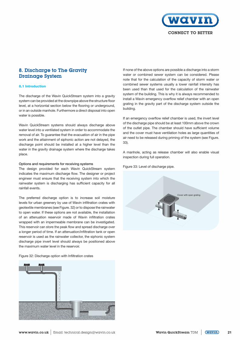
If an emergency overflow relief chamber is used, the invert level of the discharge pipe should be at least 100mm above the crownof the outlet pipe. The chamber should have sufficient volume and the cover must have ventilation holes as large quantities of air need to be released during priming of the system (see Figure. 33).
A manhole, acting as release chamber will also enable visual inspection during full operation.
Figure 33: Level of discharge pipe.
±2xD
Cover with open grating
D
Technical Design ManualQuickStream
22 Wavin QuickStream TDM Customer Services: 0844 856 5152 Technical Advice: 0844 856 5165
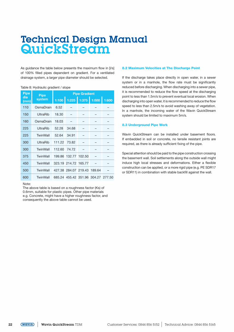
As guidance the table below presents the maximum flow in [l/s] of 100% filled pipes dependent on gradient. For a ventilated drainage system, a larger pipe diameter should be selected.
8.2 Maximum Velocities at The Discharge Point
If the discharge takes place directly in open water, in a sewer system or in a manhole, the flow rate must be significantly reduced before discharging. When discharging into a sewer pipe,it is recommended to reduce the flow speed at the discharging point to less than 1.5m/s to prevent eventual local erosion. Whendischarging into open water, it is recommended to reduce the flow speed to less than 2.5m/s to avoid washing away of vegetation. In a manhole, the incoming water of the Wavin QuickStream system should be limited to maximum 5m/s.
8.3 Underground Pipe Work
Wavin QuickStream can be installed under basement floors. If embedded in soil or concrete, no tensile resistant joints are required, as there is already sufficient fixing of the pipe.
Special attention should be paid to the pipe construction crossingthe basement wall. Soil settlements along the outside wall mightinduce high local stresses and deformations. Either a flexible construction can be applied, or a more rigid pipe (e.g. PE SDR17or SDR11) in combination with stable backfill against the wall.
Table 8: Hydraulic gradient / slope
Pipedia(mm)
Pipesystem
Pipe Gradient
1:100 1:225 1:375 1:500 1:600
110 OsmaDrain 6.52 – – – –
150 UltraRib 18.30 – – – –
160 OsmaDrain 18.03 – – – –
225 UltraRib 52.28 34.68 – – –
225 TwinWall 52.64 34.91 – – –
300 UltraRib 111.22 73.82 – – –
300 TwinWall 112.60 74.72 – – –
375 TwinWall 199.86 132.77 102.50 – –
450 TwinWall 323.19 214.72 165.77 – –
500 TwinWall 427.38 284.07 219.43 189.64 –
600 TwinWall 685.24 455.42 351.96 304.27 277.50
Note:The above table is based on a roughness factor (Ks) of 0.6mm, suitable for plastic pipes. Other pipe materials e.g. Concrete, might have a higher roughness factor, and consequently the above table cannot be used.
23www.wavin.co.uk Email: [email protected] Wavin QuickStream TDM
9. Commissioning and Maintenance
9.1 Commissioning
As a Wavin QuickStream roof drainage system operates at both positive and negative pressures, it is necessary to carry out a leak tightness test:
Close the discharge of Wavin QuickStream system and fill up the system with water to roof level
Check all the connections for leakages Unplug the discharge on completion of the inspection If the building is over 40m high, the pipe system needs to be
split up in to sections no higher than 40m
The following steps are also recommended for commissioning the system:
Check the installed system (pipe dimensions, roof drain numbers and positions). It must be ensured that the system
was implemented as per the current state of planning (dimensions, pipe guide)
Based on the planning requirements check that all fasteners (anchor points, building shell connections, fastening
distances) have been implemented as per the installation guidelines
Check the emergency run-off system. Number, positions and dimensions of wall edge openings.
In the case of emergency drainage through a separate piping system, verify that the piping system is routed to an area that can be flooded without damage. (The emergency drainage system must not be connected to the sewer system)
The roof and roof outlets must be cleaned before commissioning. While doing so, check the roof outlets for
completeness. If any components are missing, you must replace them
In the case of roof outlets for emergency drainage, check whether the back-up ring has been assembled as per the
plans
9.2 Maintenance
In line with DIN 1986-30 the following maintenance must be performed for roof drainage systems as a minimum requirement:
The roof and roof outlets must be maintained regularly. This includes, e.g. cleaning the roof and the roof outlets and
runoffs (wall edge openings). The completeness of the roof outlets must be checked. Missing components must be replaced
For roof outlets, check whether the inlet is freely accessible. To do this, you can, remove the functional part of the roof outlet. All components must be reinstalled after maintenance
Maintenance (especially cleaning) must be carried out at least twice a year, typically Spring and Autumn, directly after the trees have dropped their seeds and after leaf fall. Depending on local conditions (e.g. trees), it may be necessary to adjust the maintenance intervals
Inspect the emergency overflow chamber at least once a year
Technical Design ManualQuickStream
24 Wavin QuickStream TDM Customer Services: 0844 856 5152 Technical Advice: 0844 856 5165
10. Problem Solving / Technical Support
If after commissioning, water is observed to regularly discharge through the emergency overflows it can be concluded that the system is not functioning according to design. Possible causes for this are listed below.
Solutions related to improper installation and/or maintenance:
Accumulated dirt can hinder the flow towards the roof outlets...
Solution: clean the roof and the roof outlets Construction debris in the system reduces the flow capacity...
Solution: clean the pipe system There has been a violation with the design, e.g. a wrong pipe
diameter (too big or too small), wrong pipe lengths (e.g. tail pipes or distances from outlet to collector pipe) or the pipe layout is changed... Solution: change the pipe layout to the design made by Wavin or contact Wavin to make a new design
In violation of the design, an additional small roof or soil and waste discharge is connected to the system, through which
air is sucked into the system... Solution: change the pipe layout to the design made by Wavin or contact Wavin to make a new design
Solutions to problems caused by operating outside theprescribed design parameters or design criteria:
The main gravity sewer to which the roof drainage system discharges is over-loaded or blocked and no emergency
overflow chamber with sediment catchments has been installed...
Solution: install an emergency overflow chamber between the discharge point of the Wavin QuickStream system and the main gravity sewer system
The water level in the discharge chamber is too high at the start-up of the rainwater flow from Wavin QuickStream, preventing the escape of air... Solution: reinstall the gravity sewer pipe to a lower level or contact Wavin to discuss the implications of installing the discharge point of the Wavin QuickStream system at a higher level
High surrounding buildings might cause an uneven distribution of rainfall over the roof. Wind turbulence around a building might also cause under pressures at roof outlets...
Solution: this problem should only occur during a combination of heavy rainfall and strong winds. Usually the problem is caused by one of the other described issues
Due to high negative pressure cavities may occur, reducing the maximum flow capacity...
Solution: Wavin verifies all design on the maximum allowable negative pressure and adapts the design to such an extent that cavitation will not occur. Compare the installed system to the installation drawings made by Wavin and correct any differences
The emergency overflows have been constructed too low, preventing the build-up of a sufficient water level on the roof to enable good priming of the system. The system cannot reach its design drainage capacity while water is flushed
away through the emergency overflows... Solution: increase the heights of the emergency overflows in consultation with the building designer and Wavin
Free communications between roof outlets is hindered by obstacles...
Solution: remove obstacles or place them higher, so water can flow freely under the obstacles
Advice can also be sought from the Wavin technical team.
25www.wavin.co.uk Email: [email protected] Wavin QuickStream TDM
11. Specification of Siphonic Systems
11.1 Introduction
To secure a well designed, proper functioning and long life siphonic rainwater system it is important to incorporate the rightspecification for the design, installation, commissioning and maintenance of the system. For this purpose, the specification texts below can be used.
11.2 System Specification and Design
Roof drainage system and calculationSiphonic roof drainage system which is calculated by use of a computer aided design process. A summary of the calculation needs to be supplied to the designer of the building and shall consist at least a check on:
the maximum system imbalance of the roof outlets of 1 metre water pressure,
the maximum negative pressure of 0.9 bars, the minimum flow velocities in the horizontal pipes of 0.7
meters per second, the minimum flow velocities in the vertical downpipe of 2.0
metres per second and a calculation whether the maximum priming diameter of the vertical downpipe will be larger than the chosen internal diameter of the downpipe
Furthermore the design calculation needs to mention at least thefollowing input values which have been used for the calculation:
rainfall intensity with discharge coefficient used, pipe roughness value, roof area and the maximum water level next to the roof outlets at the design rate of siphonic system
Pipework and fixationPE pipes and fittings with a SDR 26, to be connected by use of electrofusion couplers and/or butt welding. For the vertical downpipe expansion sockets needs to be used. Fixing of the horizontal collector pipes by use of brackets and a steel rail.
Note: SDR = Standard Dimension Ratio = outside diameter/wall thickness
Roof outletsRoof outlets need to conform to EN-12056 standards and should be tested at an independent test institute which confirms compliancy with the 12056 norms.
The watertight connection between the roof outlets and the roof membrane needs to be established by fixing between two clamps or by heat welding a bitumen roof membrane to a stainless steel flange. If the roof outlet is to be fixed in a metal gutter, the watertight connection needs to be made by compressing two rubber gaskets on either side of the metal gutter between the outlet and a backing flange.
Alternatively a gutter outlet can be fixed by clamping a metal sheet of the same metal as the gutter into the outlet and weldingthe sheet into the gutter. The maximum distance between two roof outlets shall be 30 metres.
Emergency overflow systemOn every roof area, emergency overflows need to be located at amaximum intermediate distance of 30 metres. The capacity of the emergency overflow system shall be at least the design capacity of the primary rainwater system. The emergency overflows should be located as close as possible to the outlets of the primary system. The minimum height of the emergency overflow needs to be more than the maximum water level next to the roof outlets of the primary system at the design rainfall intensity as specified by the supplier of the siphonic system.
DischargeThe siphonic system shall either discharge into a ventilated pipe of at least one size larger than the siphonic system or into open water or into an emergency overflow relief chamber with an open grating.
The siphonic system should always discharge above water level into a ventilated pipe system in order to accommodate air removal.
If the siphonic system is discharging into a ventilated pipe system, this ventilated pipe system shall contain an emergency overflow relief chamber with an open grating.
The invert level of the discharge pipe of the emergency overflowrelief chamber should be at least 100mm above the crown of the outlet pipe. The installer should verify whether the receiving gravity system has sufficient capacity to discharge the design flow of the roof drainage system. The supplier of the siphonic roof drainage system needs to provide the maximum discharge flow.
11.3 Installation
The installer needs to follow the installation instructions of the supplier. The installer is not allowed to deviate from the installationdrawings supplied by the supplier unless this has been confirmedin writing by the supplier of the system.
Technical Design ManualQuickStream
26 Wavin QuickStream TDM Customer Services: 0844 856 5152 Technical Advice: 0844 856 5165
11.4 Commissioning
A leak tightness test needs to be performed conforming to the instructions supplied by the supplier of the siphonic system.
After initial commissioning of the building, a further inspection should be performed as part of the total commissioning after thefirst heavy rainfall, or at the latest within the first half year of use.
11.5 Maintenance
The frequency of inspection has to be established depending onthe local situation. The siphonic roof drainage system must be inspected at least in spring and autumn and preferably after the trees have dropped their seeds and after leaf fall. Roof and gutters must be cleared of deposits, as it is not allowed to flush the dirt through the roof outlets. All roof outlets must be inspected and checked for proper functioning by letting water run into the outlets.
The reception chamber or first inspection chamber / manhole downstream of the discharge of the siphonic system must be inspected at least once a year and if necessary all deposits haveto be removed.

27www.wavin.co.uk Email: [email protected] Wavin QuickStream TDM

NotesQuickStream
28 Wavin QuickStream TDM Customer Services: 0844 856 5152 Technical Advice: 0844 856 5165

QS
002
–
June
201
5
Discover our broad portfolio atwww.wavin.co.uk
© 2015 Wavin Limited
Wavin operates a programme of continuous product development, and therefore reserves the right to modify or amend the specification of their products without notice. All information in this publication is given in good faith, and believed to be correct at the time of going to press. However, no responsibility can be accepted for any errors, omissions or incorrect assumptions. Users should satisfy themselves that products are suitable for the purpose and application intended.
For further product information visit: wavin.co.uk
Water management | Plumbing and heating | Waste water drainageWater and gas distribution | Cable ducting
Wavin LimitedRegistered OfficeEdlington Lane Doncaster | DN12 1BYTel. 0844 856 5152www.wavin.co.uk | [email protected]