Embed Size (px)
Citation preview

International Journal of Advances in Engineering & Technology, May 2012.
©IJAET ISSN: 2231-1963
224 Vol. 3, Issue 2, pp. 224-234
WAVELET BASED VIDEO COMPRESSION USING STW, 3D-SPIHT & ASWDR TECHNIQUES: A COMPARATIVE STUDY
Abhishek Jain1 and Anjali Potnis
2
1Department of Electronics and Communication Engineering, S.A.T.I., Vidisha (M.P.)
2Department of Electronics and Communication Engineering, B.U.I.T., B.U., Bhopal (M.P.)
ABSTRACT
The objective of this paper is to implement and evaluate the effectiveness of wavelet based Spatial-orientated
Tree Wavelet (STW), 3D-Set Partitioning in hierarchical trees (3D-SPIHT) and Adaptively Scanned Wavelet
Difference Reduction (ASWDR) compression techniques using MATLAB R2010b. The performance parameters
such as Peak Signal to Noise Ratio (PSNR), Mean Squared Error (MSE), Compression Ratio (CR) and Bit-Per-
Pixel (BPP) ratio are evaluated based on the algorithms. Comparisons amongst the techniques are carried out
on the basis of calculated performance parameters. The mentioned techniques achieved better PSNR and MSE
values with respect to the Compression Ratio which makes them more efficient than the 2D-Discrete Cosine
Transform (DCT). Mentioned techniques are equally compatible for video formats like .MPEG, .DAT, .3GP,
.AVI, .FLV, .MOV etc making it more versatile.
KEYWORDS: Video Compression, STW, 3D-SPIHT, ASWDR, Wavelet, PSNR, MSE, MATLAB.
I. INTRODUCTION
The compression offers a means to reduce the cost of storage and increase the speed of transmission.
Video compression is used to minimize the size of a video file without degrading the quality of the
video. Over the past few years, a variety of powerful and sophisticated wavelet based schemes for
image and video compression have been developed and implemented [1]-[7]. Some of the most
promising are algorithms that minimize the amount of memory which the encoder or decoder must
use [8], [9]. An algorithm which is embedded and which minimizes PSNR is described in [10] (Rate-
distortion Optimized Embedding). The discrete wavelet transform (DWT) [1], [2] has gained wide
popularity due to its excellent decorrelation property, many modern image and video compression
systems embody the DWT as the intermediate transform stage. After DWT was introduced, several
codec algorithms were proposed to compress the transform coefficients as much as possible but a
compromise must be maintained between the higher compression ratio and a good perceptual quality
of image. Achieving much higher compression ratio is simply not possible without discarding some
perceptible information [1]-[10]. Thus, the rate of compression is application dependent. The most
powerful progressive method, Embedded Zerotree Wavelet (EZW) coding algorithm introduced by
Shapiro [3] combines stepwise thresholding and progressive quantization, focusing on the more
efficient way to encode the image coefficients in order to minimize the compression ratio. Among
these, Spatial-Orientation Tree Wavelet (STW) [4] and Set Partitioning in Hierarchical Trees (SPIHT)
[5] are found to be the more advantageous because of their different approach of encoding the wavelet
transform. These wavelet based image/video compression algorithms (SPIHT and STW) are
considered as refined versions of the seminal EZW algorithm [3]. The 3D-Set Partitioning in
hierarchical trees (3D-SPIHT) technique which is proposed by Kim and Pearlman [6] is the extended
form of SPIHT coding algorithm, in which the relationship among coefficients lying in different

International Journal of Advances in Engineering & Technology, May 2012.
©IJAET ISSN: 2231-1963
225 Vol. 3, Issue 2, pp. 224-234
frequency bands is based on octal tree structure rather than quad-tree structure. The most enhanced
image compression algorithm is the Adaptively Scanned Wavelet Difference Reduction (ASWDR)
algorithm proposed by Walker [11], [12]. ASWDR technique adjusts the scanning order used by
Wavelet Difference Reduction (WDR) algorithm [13] so as to predict locations of new significant
values. The WDR method employs a fixed ordering of the positions of wavelet coefficients. Thus,
ASWDR technique achieves high compression than WDR while retaining all of the important features
of WDR such as low complexity, region of interest (ROI) capability and progressive SNR capability.
This paper discusses the most powerful progressive compression techniques; all the three techniques
offer different approaches in compression. Thus a comparative study will provide a basis for other
innovative works in video compressions for superior results.
II. LITERATURE SURVEY
Video coding for telecommunication applications has evolved through the development of the
ISO/IEC MPEG-1, MPEG-2 and ITU-T H.261, H.262, H.263 video coding standards (and later
enhancements of H.263 known as H.263+ and H.263++) and H.264, [14] [15] and has diversified
from ISDN and T1/E1 service to embrace PSTN, mobile wireless networks, and LAN/Internet
network delivery. Throughout this evolution, continued efforts have been made to maximize coding
efficiency. The performance of these coders generally degrades at low bit-rates mainly because of the
underlying block-based Discrete Cosine Transform (DCT) [16] scheme. In the DCT the input image
needs to be blocked. So correlation across the block boundaries is not eliminated, resulting in
noticeable and annoying blocking artifacts. The wavelet transform resolved this difficulty of blocking
artifacts. Research in new and better methods of image and video compression is ongoing, and recent
results suggest that some newer techniques may provide much better values of performance
parameters . An extension of image compression algorithms based on wavelets and making them
suitable for video (as video contains sequence of still pictures) is essential.
Current compression systems use biorthogonal wavelet (bior wavelet family) instead of orthogonal
wavelets (Haar, Daubechies etc) [17] despite the fact that it is not energy preserving. An orthogonal
wavelet is a wavelet where the associated wavelet transform is orthogonal while in biorthogonal
wavelet, the associated wavelet transform is invertible but not necessarily orthogonal. The fact that
biorthogonal wavelets are not energy preserving is not a big problem since there are linear phase
biorthogonal filter coefficients which are close to being orthogonal [17]. The main advantage of the
biorthogonal wavelet transform is that it permits the use of a much broader class of filters, and this
class includes the symmetric filters. The biorthogonal wavelet transform is advantageous because it
can use linear phase filters which give symmetric outputs when presented with symmetric input. This
transform solves the problems of coefficient expansion and border discontinuities [17].
Embedded Zerotree Wavelet (EZW) coding algorithm introduced by Shapiro [3] combines stepwise
thresholding and progressive quantization. The Set Partitioning in Hierarchical Trees (SPIHT) [5] is
the refined versions of the seminal EZW algorithm. SPIHT performs better for high bit rate but
produces poor quality at low bit rates since it uses only the correlation between different subbands and
doesn’t consider about correlation within each subband. Set Partitioned Embedded Block Coder
(SPECK) [18] performs well at low bit rates but results in poor compression because it uses only the
correlation within each subband and doesn’t consider about correlation between different subbands. In
3D-SPIHT algorithm [6], the relationship among coefficients lying in different frequency bands is
based on octal tree structure rather than quad-tree structure.
The main property of wavelet transform in image compression is the minimum distortion in the
reconstructed image even when removal transform coefficients are near zero. In the wavelet
transform, there are two ways to decompose the pixel values for 2-dimensional image/frame; the
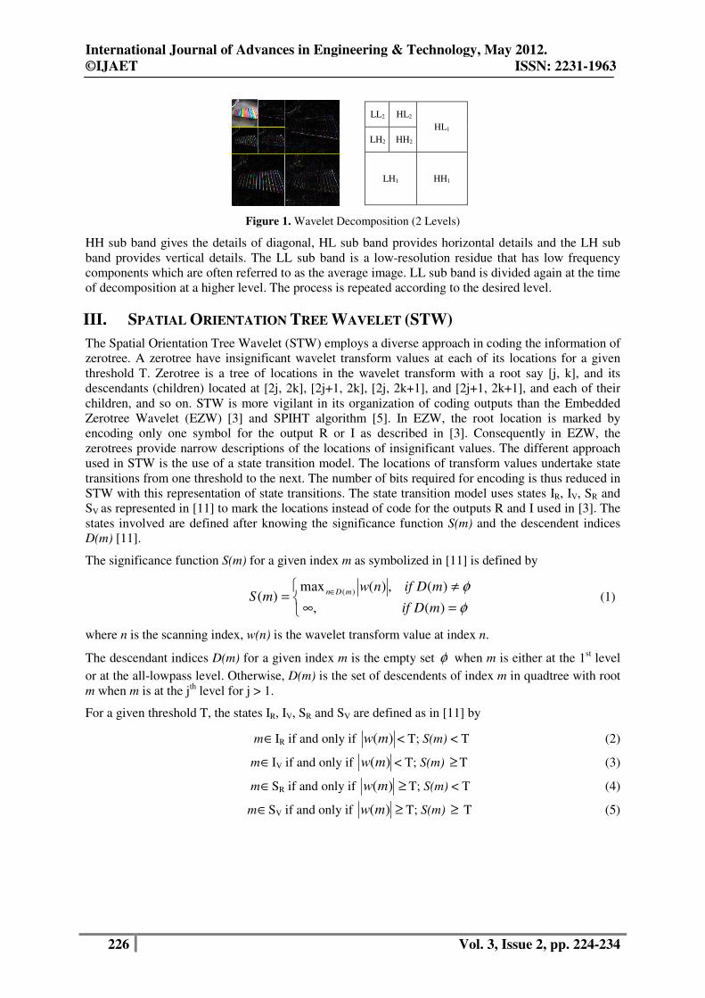
standard decomposition and nonstandard decomposition [19]. Figure 1 shows the decomposition
process for the Xylophone video frame at level 2.
The standard decomposition method is obtained based on applying wavelet transformation first on
each row and then on each column. The process results in the form of detail coefficients and
coefficient average. Nonstandard decomposition transformation is obtained by combining pairs of
rows and columns alternately. In the decomposition level 1, the image will be divided into 4 sub
bands; they are HH, HL, LH and LL sub bands.
International Journal of Advances in Engineering & Technology, May 2012.
©IJAET ISSN: 2231-1963
226 Vol. 3, Issue 2, pp. 224-234
Figure 1. Wavelet Decomposition (2 Levels)
HH sub band gives the details of diagonal, HL sub band provides horizontal details and the LH sub
band provides vertical details. The LL sub band is a low-resolution residue that has low frequency
components which are often referred to as the average image. LL sub band is divided again at the time
of decomposition at a higher level. The process is repeated according to the desired level.
III. SPATIAL ORIENTATION TREE WAVELET (STW)
The Spatial Orientation Tree Wavelet (STW) employs a diverse approach in coding the information of
zerotree. A zerotree have insignificant wavelet transform values at each of its locations for a given
threshold T. Zerotree is a tree of locations in the wavelet transform with a root say [j, k], and its
descendants (children) located at [2j, 2k], [2j+1, 2k], [2j, 2k+1], and [2j+1, 2k+1], and each of their
children, and so on. STW is more vigilant in its organization of coding outputs than the Embedded
Zerotree Wavelet (EZW) [3] and SPIHT algorithm [5]. In EZW, the root location is marked by
encoding only one symbol for the output R or I as described in [3]. Consequently in EZW, the
zerotrees provide narrow descriptions of the locations of insignificant values. The different approach
used in STW is the use of a state transition model. The locations of transform values undertake state
transitions from one threshold to the next. The number of bits required for encoding is thus reduced in
STW with this representation of state transitions. The state transition model uses states IR, IV, SR and
SV as represented in [11] to mark the locations instead of code for the outputs R and I used in [3]. The
states involved are defined after knowing the significance function S(m) and the descendent indices
D(m) [11].
The significance function S(m) for a given index m as symbolized in [11] is defined by
=∞
≠= ∈
φ
φ
)(,
)(,)(max)( )(
mDif
mDifnwmS
mDn (1)
where n is the scanning index, w(n) is the wavelet transform value at index n.
The descendant indices D(m) for a given index m is the empty set φ when m is either at the 1st level
or at the all-lowpass level. Otherwise, D(m) is the set of descendents of index m in quadtree with root
m when m is at the jth level for j > 1.
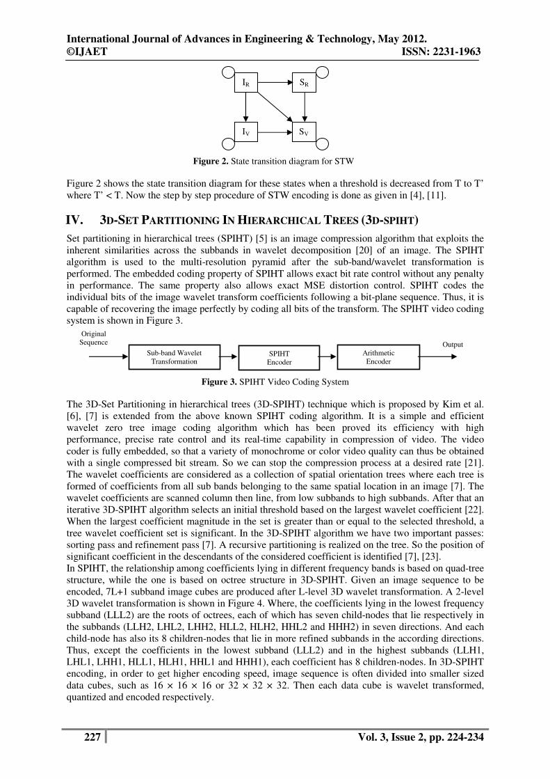
For a given threshold T, the states IR, IV, SR and SV are defined as in [11] by
m∈IR if and only if )(mw < T; S(m) < T (2)
m∈IV if and only if )(mw < T; S(m) ≥ T (3)
m∈SR if and only if ≥)(mw T; S(m) < T (4)
m∈SV if and only if ≥)(mw T; S(m) ≥ T (5)
LL2 HL2
HL1
LH2 HH2
LH1 HH1
International Journal of Advances in Engineering & Technology, May 2012.
©IJAET ISSN: 2231-1963
227 Vol. 3, Issue 2, pp. 224-234
Figure 2. State transition diagram for STW
Figure 2 shows the state transition diagram for these states when a threshold is decreased from T to T’
where T’ < T. Now the step by step procedure of STW encoding is done as given in [4], [11].
IV. 3D-SET PARTITIONING IN HIERARCHICAL TREES (3D-SPIHT)
Set partitioning in hierarchical trees (SPIHT) [5] is an image compression algorithm that exploits the
inherent similarities across the subbands in wavelet decomposition [20] of an image. The SPIHT
algorithm is used to the multi-resolution pyramid after the sub-band/wavelet transformation is
performed. The embedded coding property of SPIHT allows exact bit rate control without any penalty
in performance. The same property also allows exact MSE distortion control. SPIHT codes the
individual bits of the image wavelet transform coefficients following a bit-plane sequence. Thus, it is
capable of recovering the image perfectly by coding all bits of the transform. The SPIHT video coding
system is shown in Figure 3.
Figure 3. SPIHT Video Coding System
The 3D-Set Partitioning in hierarchical trees (3D-SPIHT) technique which is proposed by Kim et al.
[6], [7] is extended from the above known SPIHT coding algorithm. It is a simple and efficient
wavelet zero tree image coding algorithm which has been proved its efficiency with high
performance, precise rate control and its real-time capability in compression of video. The video
coder is fully embedded, so that a variety of monochrome or color video quality can thus be obtained
with a single compressed bit stream. So we can stop the compression process at a desired rate [21].
The wavelet coefficients are considered as a collection of spatial orientation trees where each tree is
formed of coefficients from all sub bands belonging to the same spatial location in an image [7]. The
wavelet coefficients are scanned column then line, from low subbands to high subbands. After that an
iterative 3D-SPIHT algorithm selects an initial threshold based on the largest wavelet coefficient [22].
When the largest coefficient magnitude in the set is greater than or equal to the selected threshold, a
tree wavelet coefficient set is significant. In the 3D-SPIHT algorithm we have two important passes:
sorting pass and refinement pass [7]. A recursive partitioning is realized on the tree. So the position of
significant coefficient in the descendants of the considered coefficient is identified [7], [23].
In SPIHT, the relationship among coefficients lying in different frequency bands is based on quad-tree
structure, while the one is based on octree structure in 3D-SPIHT. Given an image sequence to be
encoded, 7L+1 subband image cubes are produced after L-level 3D wavelet transformation. A 2-level
3D wavelet transformation is shown in Figure 4. Where, the coefficients lying in the lowest frequency
subband (LLL2) are the roots of octrees, each of which has seven child-nodes that lie respectively in
the subbands (LLH2, LHL2, LHH2, HLL2, HLH2, HHL2 and HHH2) in seven directions. And each
child-node has also its 8 children-nodes that lie in more refined subbands in the according directions.
Thus, except the coefficients in the lowest subband (LLL2) and in the highest subbands (LLH1,
LHL1, LHH1, HLL1, HLH1, HHL1 and HHH1), each coefficient has 8 children-nodes. In 3D-SPIHT
encoding, in order to get higher encoding speed, image sequence is often divided into smaller sized
data cubes, such as 16 × 16 × 16 or 32 × 32 × 32. Then each data cube is wavelet transformed,
quantized and encoded respectively.
Sub-band Wavelet
Transformation SPIHT
Encoder
Arithmetic
Encoder
Original
Sequence Output
SR
IV
IR
SV

International Journal of Advances in Engineering & Technology, May 2012.
©IJAET ISSN: 2231-1963
228 Vol. 3, Issue 2, pp. 224-234
Figure 4. 3D-Wavelet decomposition
V. ADAPTIVELY SCANNED WAVELET DIFFERENCE REDUCTION (ASWDR)
It is one of the most enhanced image compression algorithms proposed by Walker [11], [12]. The
ASWDR algorithm aims to improve the subjective perceptual qualities of compressed images and
improve the results of objective distortion measures. The ASWDR algorithm is a simple modification
of the Wavelet Difference Reduction (WDR) algorithm [13]. The WDR algorithm employs a
fixed ordering of the positions of wavelet coefficients but the ASWDR method employs a
varying order which aims to adapt itself to specific image features. ASWDR adjusts the
scanning order so as to predict locations of new significant values. The scanning order of ASWDR
dynamically adapts to the locations of edge details in an image, and this enhances the resolution of
these edges in ASWDR compressed images. Thus, ASWDR exhibits better perceptual qualities,
especially at low bit rates, than WDR and SPIHT compressed images preserving all the
features of WDR. The ASWDR on an image/frame is executed by a step by step procedure
described below [12]: Step 1: A wavelet transform is performed on the discrete image/frame f [j,k], producing the
transformed image/frame f̂ [j,k].
Step 2: A scanning order for the transformed image is chosen, f̂ [j,k] = a(m). The transform values
are scanned via a linear ordering, m = 1,2,3…..X where X is the number of pixels. In [4] and [24],
row-based scanning is used in the horizontal subbands and column-based scanning is used in the
vertical subbands with the zigzag scanning order through subbands from higher scale to lower scale
[5].
Step 3: In this step an initial threshold T is chosen. The T is chosen in such a way that at least one
transform value has magnitude less than or equal to T and all transform values have magnitudes less
than 2T.
Step 4: (Significance pass). The positions for new significant values are recorded as depicted in [12].
These new significant indices are then decoded using difference reduction [13], [24].
Step 5: (Refinement pass). Record the refinement bits, the next significant bits, for the old significant
transform values. This generation of refinement bits is also known as standard bitplane encoding
which is utilized by all embedded codecs [5], [11].
Step 6: (New scanning order). For the level containing the all-lowpass subband, the indices of the
remaining insignificant values are used as the scan order at that level. The scan order at level
k is used to create the new scan order at level k - 1as follows: Run through the significant values
(i.e. the parent values) at level k in the wavelet transform. Each parent value induces a set of four
child values for all the levels except the last. The last level induces three child values as described in
the spatial-orientation tree definition in [11]. At level k - 1, the insignificant values are enclosed in the
first part of the scan order lying among these child values. Now again run through the insignificant
values at level k in the wavelet transform. This provides the insignificant values enclosed in the
second part of the scan order lying among the child values induced by these insignificant parent
values. This new scanning order for level k - 1 is further used to create the new scanning
order for level k – 2, until all levels are exhausted.
International Journal of Advances in Engineering & Technology, May 2012.
©IJAET ISSN: 2231-1963
229 Vol. 3, Issue 2, pp. 224-234
Step 7: Divide the present threshold by 2. Repeat Steps 4-6 until either all the levels are exhausted or
a given distortion metric [12] is fulfilled.
VI. PERFORMANCE PARAMETERS
6.1. Mean Squared Error (MSE) and Peak Signal to Noise Ratio (PSNR)
Two of the error metrics used to compare the various image compression techniques are the Mean
Square Error (MSE) and the Peak Signal to Noise Ratio (PSNR). The MSE is the cumulative squared
error between the compressed and the original image, whereas PSNR is a measure of the peak error.
The phrase peak signal-to-noise ratio, often abbreviated as PSNR, is an engineering term for the ratio
between the maximum possible power of a signal and the power of corrupting noise that affects the
fidelity of its representation. Because many signals have a very wide dynamic range, PSNR is usually
expressed in terms of the logarithmic decibel scale.
The PSNR is most commonly used as a measure of quality of reconstruction of lossy compression
codecs [1]-[10]. The signal in this case is the original data, and the noise is the error introduced by
compression. When comparing compression codecs it is used as an approximation to human
perception of reconstruction quality, therefore in some cases one reconstruction may appear to be
closer to the original than another, even though it has a lower PSNR (a higher PSNR would normally
indicate that the reconstruction is of higher quality). One has to be extremely careful with the range of
validity of this metric; it is only conclusively valid when it is used to compare results from the same
codec (or codec type) and same content. It is most easily defined via the mean squared error (MSE)
which for two m × n images I and K where one of the images is considered a noisy approximation of
the other is defined as:
[ ]∑∑=
−
=
−=1
0
1
0
2),(),(
1MSE
m-
i
n
j
jiKjiImn
(3)
The PSNR is defined as:
⋅=
MSE
MAXlog 10PSNR
2
I10 (4)
⋅=
MSE
MAXlog 20PSNR I
10 (5)
Here, MAXI is the maximum possible pixel value of the image. When the pixels are represented using
8 bits per sample, this is 255. More generally, when samples are represented using linear PCM with B
bits per sample, MAXI is 2B−1. For color images with three RGB values per pixel, the definition of
PSNR is the same except the MSE is the sum over all squared value differences divided by image size
and by three. Alternately, for color images the image is converted to a different color space and PSNR
is reported against each channel of that color space.
6.2. Compression Ratio (CR) and Bit-Per-Pixel (BPP)
A measure of achieved compression is given by the Compression Ratio (CR) and the Bit-Per-Pixel
(BPP) ratio. CR and BPP represent equivalent information. CR indicates that the compressed image is
stored using CR % of the initial storage size while BPP is the number of bits used to store one pixel of
the image. For a greyscale image the initial BPP is 8. For a true color image the initial BPP is 24,
because 8 bits are used to encode each of the three colors (RGB color space). The challenge of
compression methods is to find the best compromise between a low compression ratio and a good
perceptual result.
VII. RESULTS AND DISCUSSION
The original video is split in the form of frames which is further subdivided into blocks to compute
the 2D motion vectors per block and to perform motion compensation and estimation [25]. Each
International Journal of Advances in Engineering & Technology, May 2012.
©IJAET ISSN: 2231-1963
230 Vol. 3, Issue 2, pp. 224-234
frame is then compressed by these algorithms for various maxloop which is the number of steps for a
particular compression algorithm. For any significant compression methods, the parameter ‘maxloop’
decides the maximum number of steps of the compression algorithm the default parameter value is
‘10’ and the user can select any positive integer for this parameter value. The maxloop for the
algorithms is selected on the basis of the preferred compression ratio (CR) and bit-per-pixel (BPP)
ratio keeping the best compromise between a low compression ratio and a good perceptual result. The
wavelet which is used in our experiment is biorthogonal spline wavelet 4.4 (bior 4.4) [1], [2] because
of its advantages as mentioned in the literature review section. The video which we are taking is in
mpeg format which is a standard Xylophone movie clip of 645 KB. The techniques are also validated
for different video formats like .DAT, .3GP, .AVI, .FLV, .MOV etc by acquiring these formats for the
Xylophone clip. Thus these algorithms provide compatibility for various video formats. The
simulation results are nearly same for all the formats for Xylophone clip. Comparisons amongst the
techniques are carried out for the mpeg format. Following general and video configurations are
obtained in MATLAB R2010b for the Xylophone clip.
General Configuration:
Duration = 4.7020
Name = ABC.mpg
Tag = My reader object
Type = VideoReader
UserData = []
Video Configuration:
BitsPerPixel = 24
FrameRate = 29.9700
Height = 240
NumberOfFrames = 141
VideoFormat = RGB24
Width = 320
Total Bitrate = 1064Kbps
Data rate = 1000Kbps
The simulation results of video compression by applying the Spatial-orientation Tree Wavelet (STW),
3D-Set Partitioning in hierarchical trees (3D-SPIHT) and Adaptively Scanned Wavelet Difference
Reduction (ASWDR) algorithms various comparisons are obtained on the basis of PSNR and MSE
values for the particular compression ratio (CR) and bit-per-pixel (BPP) ratio.
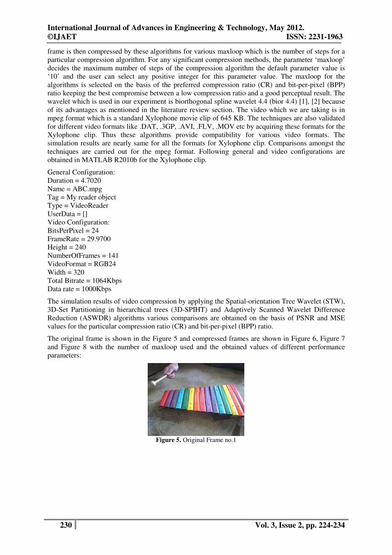
The original frame is shown in the Figure 5 and compressed frames are shown in Figure 6, Figure 7
and Figure 8 with the number of maxloop used and the obtained values of different performance
parameters:
Figure 5. Original Frame no.1
International Journal of Advances in Engineering & Technology, May 2012.
©IJAET ISSN: 2231-1963
231 Vol. 3, Issue 2, pp. 224-234
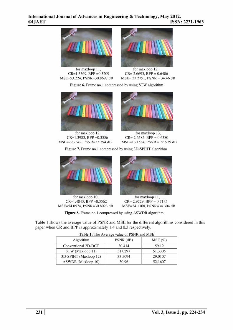
for maxloop 11, for maxloop 12,
CR=1.3369, BPP =0.3209 CR= 2.6693, BPP = 0.6406
MSE=53.224, PSNR=30.8697 dB MSE= 23.2751, PSNR = 34.46 dB
Figure 6. Frame no.1 compressed by using STW algorithm
for maxloop 12, for maxloop 13,
CR=1.3983, BPP =0.3356 CR= 2.6585, BPP = 0.6380
MSE=29.7642, PSNR=33.394 dB MSE=13.1584, PSNR = 36.939 dB
Figure 7. Frame no.1 compressed by using 3D-SPIHT algorithm
for maxloop 10, for maxloop 11,
CR=1.4843, BPP =0.3562 CR= 2.9729, BPP = 0.7135
MSE=54.0574, PSNR=30.8023 dB MSE=24.1368, PSNR=34.304 dB
Figure 8. Frame no.1 compressed by using ASWDR algorithm
Table 1 shows the average value of PSNR and MSE for the different algorithms considered in this
paper when CR and BPP is approximately 1.4 and 0.3 respectively.
Table 1: The Average value of PSNR and MSE
Algorithm PSNR (dB) MSE (%)
Conventional 2D-DCT 30.414 59.12
STW (Maxloop 11) 31.0297 51.3305
3D-SPIHT (Maxloop 12) 33.5094 29.0107
ASWDR (Maxloop 10) 30.96 52.1607
International Journal of Advances in Engineering & Technology, May 2012.
©IJAET ISSN: 2231-1963
232 Vol. 3, Issue 2, pp. 224-234
Figure 9. Average value of PSNR and MSE when the CR and the BPP is approximately 1.4 and 0.3
respectively.
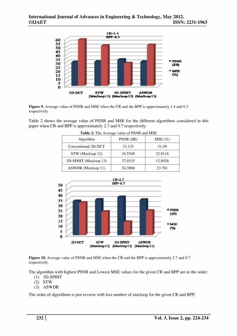
Table 2 shows the average value of PSNR and MSE for the different algorithms considered in this
paper when CR and BPP is approximately 2.7 and 0.7 respectively.
Table 2: The Average value of PSNR and MSE
Algorithm PSNR (dB) MSE (%)
Conventional 2D-DCT 33.135 31.59
STW (Maxloop 12) 34.5548 22.8116
3D-SPIHT (Maxloop 13) 37.0335 12.8926
ASWDR (Maxloop 11) 34.3888 23.701
Figure 10. Average value of PSNR and MSE when the CR and the BPP is approximately 2.7 and 0.7
respectively.
The algorithm with highest PSNR and Lowest MSE values for the given CR and BPP are in the order:
(1) 3D-SPIHT
(2) STW
(3) ASWDR
The order of algorithms is just reverse with less number of maxloop for the given CR and BPP.
International Journal of Advances in Engineering & Technology, May 2012.
©IJAET ISSN: 2231-1963
233 Vol. 3, Issue 2, pp. 224-234
VIII. CONCLUSION
Spatial-orientation Tree Wavelet (STW), 3D-Set Partitioning in hierarchical trees (3D-SPIHT)
and Adaptively Scanned Wavelet Difference Reduction (ASWDR) algorithms are implemented
for video compression and the results are compared. The original video is split in the form of
frames which is further subdivided into blocks via block matching algorithm [26]. Each frame is then
compressed and decompressed by these algorithms. The average MSE and PSNR values are
considered as a quality parameter for the video quality. On the basis of the preferred compression
ratio (CR) and bit-per-pixel (BPP) ratio, maxloop for the compression algorithm is selected. The
selection of maxloop is done keeping the best compromise between a low compression ratio and a
good perceptual result. Less number of maxloop provide smaller compression time because of
less number of steps. Comparisons amongst the techniques are carried out on the basis of calculated performance
parameters. The results show that the PSNR and MSE value are 8% better in 3D-SPIHT as compared
to STW and ASWDR methods. So 3D-SPIHT can be used for the video compression, where lower
BPP is vital. In context to minimum number of maxloop, ASWDR is better than the other two
algorithms which can be used where higher perceptual quality is essential rather than the lower BPP.
These algorithms sustain faithful compression and reproduction of the video, preserving the picture
quality. In future, many methodological aspects like choice of the mother wavelet, scale parameters,
threshold values etc of the wavelet technique will always require further investigations and can lead
for enhanced outcome.
REFERENCES
[1] R. A. DeVore, B. Jawerth, and B. J. Lucier, "Image compression through wavelet transform coding,”
IEEE Transactions on Information Theory, vol. 38, no.2, pp. 719-746, March 1992.
[2] A. S. Lewis and G. Knowles, “Image compression using the 2-D wavelet transform,” IEEE
Transactions on Image Processing, vol. 1, no. 2, pp. 244-250, April 1992.
[3] J. M. Shapiro, “Embedded image coding using zerotrees of wavelet coefficients,” IEEE Transactions
on Signal Processing, vol. 41, no. 12, pp. 3445-3462, 1993.
[4] A. Said and W. A. Pearlman. “Image compression using the spatial-orientation tree,” IEEE
International Symosium On Circuits and Systems, Chicago, IL, pp. 279-282, 1993.
[5] A. Said and W. A. Pearlman, “A new, fast and efficient image codec based on set partitioning in
hierarchical trees,” IEEE Transactions on Circuits and Systems for Video Technology, vol. 6, no. 3, pp.
243-250, 1996.
[6] B. J. Kim and Pearlman, “An Embedded Wavelet Video Coder using Three-Dimensional Set
Partitioning in Hierarchical Trees (3D-SPIHT),” in Proc. of Data Compression Conference 1997,
Snowbird, USA, March 1997, pp. 251-260.
[7] B. J. Kim, Z. Xiong, and W. A. Pearlman, “Low bit-rate scalable video coding with 3-D set partitioning
in hierarchical trees (3-D SPIHT),” IEEE Transactions on Circuits and Systems for Video Technology,
vol. 10, pp. 1374-1387, Dec. 2000.
[8] A. Islam and W.A. Pearlman, “An embedded and efficient low-complexity hierarchical image coder,”
in Proc. of SPIE 1999, Visual Communications and Image Processing, San Jose, CA, vol. 3653, pp.
294-305, Jan. 1999.
[9] H. Malvar, “Progressive wavelet coding of images,” in Proc. of IEEE Data Compression Conference
(DCC’99), Salt Lake City, UT, March 1999, pp. 336-343.
[10] J. Li and S. Lei, “An embedded still image coder with rate-distortion optimization,” IEEE Transactions
on Image Processing, vol. 8, no. 7, pp. 913-924, 1999.
[11] James S. Walker, “Wavelet-based Image Compression,” in Transforms and Data Compression
handbook, CRC Press LLC, Boca Raton, 2001.
[12] J. S. Walker and T.O. Nguyen, “Adaptive scanning methods for wavelet difference reduction in lossy
image compression,” in Proc. of IEEE International Conference on Image Processing, vol.3,
Vancouver, Canada, Sep. 2000, pp. 182-185.
[13] J. Tian and R.O. Wells, “A lossy image codec based on index coding & embedded image coding using
wavelet difference reduction,” in Proc. of IEEE Data Compression Conference (DCC’96), 1996, page
456.
[14] K. Rao and J. Hwang, Techniques and Standards for Image, Video, and Audio Coding, Prentice Hall,
Upper Saddle River, NJ, 1996.

International Journal of Advances in Engineering & Technology, May 2012.
©IJAET ISSN: 2231-1963
232 Vol. 3, Issue 2, pp. 224-234
Figure 9. Average value of PSNR and MSE when the CR and the BPP is approximately 1.4 and 0.3
respectively.
Table 2 shows the average value of PSNR and MSE for the different algorithms considered in this
paper when CR and BPP is approximately 2.7 and 0.7 respectively.
Table 2: The Average value of PSNR and MSE
Algorithm PSNR (dB) MSE (%)
Conventional 2D-DCT 33.135 31.59
STW (Maxloop 12) 34.5548 22.8116
3D-SPIHT (Maxloop 13) 37.0335 12.8926
ASWDR (Maxloop 11) 34.3888 23.701
Figure 10. Average value of PSNR and MSE when the CR and the BPP is approximately 2.7 and 0.7
respectively.
The algorithm with highest PSNR and Lowest MSE values for the given CR and BPP are in the order:
(1) 3D-SPIHT
(2) STW
(3) ASWDR
The order of algorithms is just reverse with less number of maxloop for the given CR and BPP.
International Journal of Advances in Engineering & Technology, May 2012.
©IJAET ISSN: 2231-1963
234 Vol. 3, Issue 2, pp. 224-234
[15] T. Wiegand, G. Sullivan, G. Bjontegaard, and A. Luthra, “Overview of the H.264/AVC Video Coding
Standard,” IEEE Transactions on Circuits System Video Technology, pp. 243-250, 2003.
[16] K. Rao and P. Yip, Discrete Cosine Transforms: Algorithms, Advantages, Applications, Academic
Press, Boston MA, 1990.
[17] B. E. Usevitch, “A Tutorial on Modern Lossy Wavelet Image Compression: Foundations of JPEG
2000,” in IEEE Signal processing Magazine, vol. 18, no. 5, pp. 22-35, Sep. 2001.
[18] W. A. Pearlman, A. Islam, N. Nagaraj, and A. Said, “Efficient, Low-Complexity Image Coding with a
Set-Partitioning Embedded Block Coder,” IEEE Transactions on Circuits and Systems for Video
Technology, vol. 14, no.11, pp. 1219-1235, 2004.
[19] E. J. Stollnitz, T. D. DeRose, D. H. Salesin, Wavelets For Computer Graphics: Theory and
Applications, Morgan Kaufman Publisher, USA, San Fransisco, 1996.
[20] N. Treil, S. Mallat and R. Bajcsy, “Image Wavelet Decomposition and Application,” GRASP Lab 207,
University of Pennsylvania, Philadelphia, Technical Report MS-CIS-89-22, April 1989.
[21] P. N. Topiwala, Wavelet image and video compression, Kluwer Academic Publishers, Norwell, MA,
1998, pp. 289–301.
[22] K. R. Namuduri and V. N. Ramaswamy, “Feature preserving image compression,” in Pattern
Recognition Letters, vol. 24, no. 15, pp. 2767-2776, Nov. 2003.
[23] X. Qi and M. Tyler, "A progressive transmission capable diagnostically lossless compression scheme
for 3D medical image sets,” International Journal of Information Science, vol. 175, pp. 217-243, 2005.
[24] M. Antonini, M. Barlaud, P. Mathieu, and I. Daubechies, “Image coding using wavelet transform,”
IEEE Transactions on Image Processing, vol. 1, no. 2, pp. 205-220, 1992.
[25] K.-C. Hui and W.C. Siu, “Extended analysis of motion compensated frame difference for block-based
motion prediction error,” IEEE Transactions on Image Processing, vol. 16, no. 5, pp. 1232–1245, May
2007.
[26] Yih-Chuan Lin and Shen-Chuan Tai, “Fast Full-Search Block-Matching Algorithm for Motion-
Compensated Video Compression” IEEE Transactions on Communications, vol. 45, no. 5, pp. 527-53,
May 1997.
Authors:
Abhishek Jain is working as an Assistant Professor in Electronics &
Communication Department at SATI Engineering College, Vidisha (M.P), India
since 2007. He holds a B. E. degree in Electronics & Communication Engineering
from Rajiv Gandhi Technical University, Bhopal and an M.Tech. (Hons.) degree in
Digital Communication from Barkatullah University, Bhopal (M.P.), India. His areas
of interest include digital communication, digital image processing, data
communication and microprocessor. Anjali Potnis received her Bachelor’s degree in Electronics, Masters degree in
Digital Communication and Ph.D.in Electronics and communication Engineering
from MANIT, Bhopal (M.P), India. Her research interests are signal processing,
image processing and digital communication. She has more than 15 years of teaching
experience in various engineering colleges, presently she is working as senior faculty
in the Department of Electronics and Communication Engineering, Barkatullah
University Institute of Technology, Barkatullah University, Bhopal (M.P.), India.