Embed Size (px)
Citation preview

pinholewaveguide
MM,dima@ILS
abstract
overview
loss estimation
experiment
experiment 0
deflection
focusing
summary
appendix
. . . . . .
Waveguide Composed of Pinhole Array
M. Morinaga and D. Kouznetsov
Institute for Laser Science, UECChofu, Tokyo 182-8585, JAPAN
2012-10-05 IWLS

pinholewaveguide
MM,dima@ILS
abstract
overview
loss estimation
experiment
experiment 0
deflection
focusing
summary
appendix
. . . . . .
abstract
A waveguide composed of an array of pinholes is proposed.Intensity loss at each pinhole is shown to be proportional toL1.5 where L is the distance between adjascent pinholes. Thusby increasing the number of pinholes 4 times, the loss for unitlength becomes a half. Experimental demonstration of suchwaveguide is also given.

pinholewaveguide
MM,dima@ILS
abstract
overview
loss estimation
experiment
experiment 0
deflection
focusing
summary
appendix
. . . . . .
guiding of wave (light, atoms,...) with
pinholes/slits
λ =1064nm, 532nm

pinholewaveguide
MM,dima@ILS
abstract
overview
loss estimation
experiment
experiment 0
deflection
focusing
summary
appendix
. . . . . .
wave
In In+1 In+2I0
L
2d
In+1 =
{1 − β
(λLd2
) 32
}In
By reducing the pinhole/slit spacing 1/4 the loss par unitlength becomes a half!

pinholewaveguide
MM,dima@ILS
abstract
overview
loss estimation
experiment
experiment 0
deflection
focusing
summary
appendix
. . . . . .
Propagation through the pinhole array
Propagation process can be devided into two parts:
..1 Free propagation between two neighboring slits
TL =
∫ ∞
−∞dk |k⟩eikzL⟨k| = eiϕ0
∫ ∞
−∞dk |k⟩e−iαk2⟨k|
k20 = k2z + k2 → kz ∼ k0 − k2
2k0→ α = L
2k0
..2 Masking of wavefunction when the wave pass through aslit
(TMψ)(x) =
{ψ(x) |x| < d0 otherwise
..3 T ≡ TM TL
..4 Propagation through many slits: Tn
..5 Find eigenvalue and eigenstate of T

pinholewaveguide
MM,dima@ILS
abstract
overview
loss estimation
experiment
experiment 0
deflection
focusing
summary
appendix
. . . . . .
Wavefunction just after a slit
• Takes nonzero value only inside the opening
• Can be expanded with sin/cos function that are 0 on theslit boundary:
ψn(x) =
c0 cos knx (n : even)c0 sin knx (n : odd)
(−d ≤ x ≤ d)
0 (otherwise)
kn = n+12d π (n = 0, 1, 2, ...)
c0 = 1√d: normalization constant
(ψn are eigenfunctions of “Particle in a Box”)

pinholewaveguide
MM,dima@ILS
abstract
overview
loss estimation
experiment
experiment 0
deflection
focusing
summary
appendix
. . . . . .
1 − |Tnn|
1e-014
1e-012
1e-010
1e-008
1e-006
0.0001
0.01
1
100
1e-007 1e-006 1e-005 0.0001 0.001 0.01 0.1 1 10
"diag_.txt" u 1:2"diag_.txt" u 1:3"diag_.txt" u 1:4"diag_.txt" u 1:5"diag_.txt" u 1:6"diag_.txt" u 1:7
f(1,x)f(2,x)f(3,x)f(4,x)f(5,x)f(6,x)
pinholewaveguide
MM,dima@ILS
abstract
overview
loss estimation
experiment
experiment 0
deflection
focusing
summary
appendix
. . . . . .
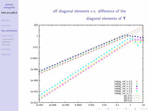
off diagonal elements v.s. difference of the
diagonal elements of T
1e-012
1e-010
1e-008
1e-006
0.0001
0.01
1
100
1e-007 1e-006 1e-005 0.0001 0.001 0.01 0.1 1 10
"odiag_.txt" u 1:2"odiag_.txt" u 1:3"odiag_.txt" u 1:4"odiag_.txt" u 1:5"odiag_.txt" u 1:6"odiag_.txt" u 1:7
g(1,3,x)g(1,5,x)g(3,5,x)

pinholewaveguide
MM,dima@ILS
abstract
overview
loss estimation
experiment
experiment 0
deflection
focusing
summary
appendix
. . . . . .
asymptotic form of the operator T
Tmn = δmn exp(−i (m+1)2π2
8Lkd2
)+1+(−1)m+n
2 (m + 1)(n + 1)π32
12
(Lkd2
) 32(−1 − i)
+O
((Lkd2
)2)
amplitude loss par single unit of slit (length L):
1 − |Tmm| = (m + 1)2π
32
12
(L
kd2
) 32
+ O
((L
kd2
)2)

pinholewaveguide
MM,dima@ILS
abstract
overview
loss estimation
experiment
experiment 0
deflection
focusing
summary
appendix
. . . . . .
eigenstates & eigenvalues of T
• difference of the diagonal elements: O(λLd2
)• off-diagonal elements: O
(λLd2
)1.5
When λLd2
→ 0
• ψn become eigenstates
• Tnn become eigenvalues

pinholewaveguide
MM,dima@ILS
abstract
overview
loss estimation
experiment
experiment 0
deflection
focusing
summary
appendix
. . . . . .
light power after the pinhole no.9
0
20
40
60
80
100
120
140
160
0 1 2 3 4 5 6 7 8 9
tran
smis
sion
inte
nsity
(a.
u.)
number of pinholes
λ = 532nm
ϕ = 0.5mm
L = 45mm
0: pinhole no.9 only,1: pinhole no.9 + no.0,2: pinhole no.9 + no.0 + no.1,...
160 in the vertical axis corresponds to about 50% of light power
transmitted through pinhole no.0.

pinholewaveguide
MM,dima@ILS
abstract
overview
loss estimation
experiment
experiment 0
deflection
focusing
summary
appendix
. . . . . .
light power after each pinhole
0.2
0.3
0.4
0.5
0.6
0.7
0.8
0.9
1
1 2 3 4 5 6 7 8 9 10
norm
aliz
ed tr
ansm
issi
on in
tens
ity
detector position
532nm1064nm

pinholewaveguide
MM,dima@ILS
abstract
overview
loss estimation
experiment
experiment 0
deflection
focusing
summary
appendix
. . . . . .
beam profile after pinhole no.0 and no.3
λ = 532nm, ϕ = 0.5mm, L = 45mm

pinholewaveguide
MM,dima@ILS
abstract
overview
loss estimation
experiment
experiment 0
deflection
focusing
summary
appendix
. . . . . .
beam deflection
0
0.2
0.4
0.6
0.8
1
0 0.5 1 1.5 2
norm
aliz
ed tr
ansm
issi
on in
tens
ity
displacement of the last pinhole [mm]
experimentgeometrical optics
λ = 532nm, ϕ = 0.5mm, L = 45mm

pinholewaveguide
MM,dima@ILS
abstract
overview
loss estimation
experiment
experiment 0
deflection
focusing
summary
appendix
. . . . . .
beam focusing
35mm80mm322mm
planewave 1 2 3 image
sensor
λ=1064nmφ=1.0mm
0
20
40
60
80
100
120
140
160
180
200
0 100 200 300 400 500 600 700 800 900 1000
inte
nsity
(a.
u.)
pixel
1 pinhole2 pinholes3 pinholes

pinholewaveguide
MM,dima@ILS
abstract
overview
loss estimation
experiment
experiment 0
deflection
focusing
summary
appendix
. . . . . .
features of this methodsapplication
• Any kind of wave can be handled• electro-magnetic wave of special wavelength, matter wave,
etc.
• possible to bend• wave travels through a free space
• guide atoms by the light guided by the pinhole array
• manipulation of the transverse mode
• FREE beam profiling program for WDM cameras (USBcameras) is available at: http://m.ils.uec.ac.jp/sbpw/

pinholewaveguide
MM,dima@ILS
abstract
overview
loss estimation
experiment
experiment 0
deflection
focusing
summary
appendix
. . . . . .
pinhole aligning ROBOT(under construction)
number of pinholes: ∼ 100pinhole spacing: & 2mm
pinholewaveguide
MM,dima@ILS
abstract
overview
loss estimation
experiment
experiment 0
deflection
focusing
summary
appendix
. . . . . .
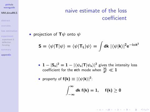
naive estimate of the losscoefficient
• projection of Tψ onto ψ
S = ⟨ψ|T|ψ⟩ = ⟨ψ|TL|ψ⟩ =
∫dk |⟨ψ|k⟩|2e−iαk2
• 1 − |Sn|2 = 1 − |⟨ψn|T|ψn⟩|2 gives the intensity losscoefficient for the nth mode when λL
d2≪ 1
• property of f(k) ≡ |⟨ψ|k⟩|2:∫ ∞
−∞dk f(k) = 1, f(k) ≥ 0

pinholewaveguide
MM,dima@ILS
abstract
overview
loss estimation
experiment
experiment 0
deflection
focusing
summary
appendix
. . . . . .
fn(k) ≡ |⟨ψn|k⟩|2fn(k)
k-kc kc0
δk
kc = n+12d π、δk ∼ π
2d。
kc ≡∫ ∞
0dk k{f(k) + f(−k)}
δk ≡(∫ ∞
0dk (k − kc)
2{f(k) + f(−k)}) 1
2

pinholewaveguide
MM,dima@ILS
abstract
overview
loss estimation
experiment
experiment 0
deflection
focusing
summary
appendix
. . . . . .
S= ⟨ψ|T|ψ⟩=
∫∞−∞ dk f(k)e−iαk2
= e−iαk2c∫∞0 dk {f(k) + f(−k)}e−iα(2kc∆k+∆k2)
∼ e−iαk2c∫∞0 dk g(k){1 − iα(2kc∆k + ∆k2) − 2α2k2c∆k2}
= e−iαk2c{1 + (−iα− 2α2k2c)δk2}
|S|2 ∼ 1 − 4α2k2cδk2 = 1 −
k2cδk2
k20L2
|Sn|2 ∼ 1 −(n + 1)2π4
16k20d4
L2 = 1 −(n + 1)2π2
64
(λL
d2
)2
wrong result!
g(k) = f(k) + f(−k), ∆k ≡ k − kc.