Embed Size (px)
Citation preview

Water Supply Code of Australia Hunter Water Corporation
Version 1.0
WATER SERVICES A SSOCIATIONOF AUSTR ALIA
WSA 03–2002
HUNTER WATER EDITION VERSION 1 COPYRIGHT DECEMBER 2009
Water Supply Code of Australia
WSA 03—2002-2.3
Hunter Water Edition
Version 1
Previous edition WSA 03: 1999

HUNTER WATER EDITION VERSION 1 COPYRIGHT DECEMBER 2009
CONTENTS PREFACE 6 INTRODUCTION 9
PART 0: GLOSSARY OF TERMS AND ABBREVIATIONS
I Glossary of Terms 14
II Abbreviations 25
III Referenced Documents 28
IV Other References 32
PART 1: PLANNING AND DESIGN
Contents 36
1 General 42
2 System Planning 56
3 Hydraulic Design 71
4 General Design 80
5 Structural Design 100
6 Appurtenances 113
7 Design Review and Drawings 133
PART 2: PRODUCTS AND MATERIALS
Contents 138
8 Products and Materials Overview 140
Appendix A Quality Assurance of Products and Materials 151
PART 3: CONSTRUCTION
Contents 158
9 General 162
10 Quality – Not used 163
11 General Construction – Not used 164
12 Products and Materials 165
13 Excavation 166
14 Bedding for Pipes 169
15 Pipe Laying and Jointing 170
16 Pipe Embedment and Support 173
17 Fill 174
18 Swabbing 176
19 Acceptance Testing 178
20 Disinfection – Not used 180
WSA 03—2002
HUNTER WATER EDITION VERSION 1 COPYRIGHT DECEMBER 2009
4
21 Tolerances on As-Constructed Work 181
22 Connections to Existing Water Mains 182
23 Restoration 183
24 Work As Constructed Details – Not used 185
PART 4: STANDARD DRAWINGS Contents 188
25 Introduction 190
26 Listing of Standard Drawings 192
27 Commentary on WAT-1100 Series Drawings 195
28 Commentary on WAT-1200 Series Drawings 199
29 Commentary on WAT-1300 Series Drawings 204
30 Commentary on WAT-1400 Series Drawings 207
STANDARD DRAWINGS 210
WAT-1100 Series Drawings – Pipeline Layout
WAT-1200 Series Drawings – Embedment, Trench Fill And Restraints
WAT-1300 Series Drawings – Installation Practices And Structures
WAT-1400 Series Drawings – Fabrication Details
HUNTER WATER APPENDICES HW1 Environmental Considerations
HW2 Water Mains in Slip and Potentially Unstable Areas
HW3A Drawing Requirements
HW3B Work As Constructed Drawings
HW4 Under Pressure Cut-In Connections
HW5 Telemetry Signal Requirements

HUNTER WATER EDITION VERSION 1 COPYRIGHT DECEMBER 2009
Water Supply Code of Australia
WSA 03—2002-2.3
Hunter Water Edition
Version 1
Part 1: Planning and Design
WSA 03—2002-2.3
HUNTER WATER EDITION VERSION 1 COPYRIGHT DECEMBER 2009
36
CONTENTS
1 GENERAL 1.1 SCOPE 1.2 PLANNING AND DESIGN OBJECTIVES
1.2.1 Overview 1.2.2 Design life 1.2.3 Design requirements 1.2.4 Terrorism HW 1.2.5 Safety in design HW 1.2.6 HW Instrumentation and control systems
1.3 PLANNING OUTPUT 1.4 DESIGN OUTPUT 1.5 DESIGN RESPONSIBILITIES
1.5.1 General 1.5.2 Water Agency 1.5.3 The Designer
1.6 CONSULTATION WITH OTHER PARTIES HW 1.7 SERVICING STRATEGIES
HW 1.7.1 Regional Servicing Strategies HW 1.7.2 Local Servicing Strategies HW 1.7.3 Servicing Strategies – Security of supply HW 1.7.4 Validity of strategies and designs
HW 1.8 CONCEPT PLAN HW 1.9 DETAIL DESIGN
2 SYSTEM PLANNING 2.1 SYSTEM PLANNING PROCESS
2.1.1 Extending / upgrading an existing water supply system 2.1.2 Providing a new water supply
2.2 DEMANDS 2.2.1 General 2.2.2 Assessment of demand—Forecast of future demand
2.2.2.1 General 2.2.2.2 Residential 2.2.2.3 Non-residential HW 2.2.2.4 Unaccounted water
HW 2.2.3 Demands categories HW 2.2.3.1 Average day demand HW 2.2.3.2 Peak day demand HW 2.2.3.3 Extreme day demand HW 2.2.3.4 Peak and extreme week demands HW 2.2.3.5 Diurnal demand HW 2.2.3.6 95th percentile peak day demand HW 2.2.3.7 Fire fighting
2.3 SYSTEM CONFIGURATION 2.4 SYSTEM HYDRAULICS
2.4.1 General 2.4.2 Network analysis 2.4.3 Operating pressures
2.4.3.1 Service pressure

WSA 03—2002-2.3
HUNTER WATER EDITION VERSION 1 COPYRIGHT DECEMBER 2009
37
2.4.3.2 Maximum allowable service pressure 2.4.3.3 Minimum allowable service pressure HW 2.4.3.4 Average service pressure
2.4.4 Pressure variation analysis 2.4.5 Determining supply zones
2.5 WATER QUALITY 2.5.1 General 2.5.2 Prevention of back siphonage 2.5.3 Water age 2.5.4 Disinfection
2.6 PUMPING STATIONS 2.7 SERVICE RESERVOIRS 2.8 FUTURE SYSTEM EXPANSION 2.9 SYSTEM REVIEW 2.10 CONCEPT PLAN
3 HYDRAULIC DESIGN 3.1 DESIGN INPUTS AND OUTPUTS 3.2 SIZING OF MAINS
3.2.1 General 3.2.2 Minimum pipe sizes 3.2.3 Empirical sizing of reticulation mains 3.2.4 Fire flows 3.2.5 Sizing by analysis
3.2.5.1 General 3.2.5.2 Head losses 3.2.5.3 Hydraulic roughness values 3.2.5.4 Flow velocities
3.3 PRESSURE DESIGNATIONS 3.4 DESIGN PRESSURES
3.4.1 General 3.4.2 Maximum design pressure HW 3.4.3 Minimum design pressure
3.5 DESIGN FOR SURGE AND FATIGUE 3.5.1 General 3.5.2 Surge 3.5.3 Fatigue
HW 3.5.3.1 Fatigue design for thermoplastic pipes HW 3.5.3.2 Fatigue design for thermoplastic fittings HW 3.5.3.3 Metallic pipes and fittings
3.6 TEMPERATURE DE-RATING OF PLASTIC PIPES AND FITTINGS 3.7 PIPE AND FITTINGS PRESSURE CLASS
3.7.1 Maximum allowable operating pressure (MAOP) 3.7.1.1 Thermoplastic pipes and fittings MAOP 3.7.1.2 Ductile iron pipes and fittings MAOP
3.7.2 Minimum pressure class HW 3.7.3 Maximum cyclic pressure range – Thermoplastic pipes and fittings
3.8 PIPELINE MATERIALS
4 GENERAL DESIGN 4.1 GENERAL REQUIREMENTS

WSA 03—2002-2.3
HUNTER WATER EDITION VERSION 1 COPYRIGHT DECEMBER 2009
38
4.1.1 Design tolerances and Survey Control HW 4.1.1.1 Survey Control
4.1.2 Levels 4.1.3 Water main renewals—electrical earthing to water services 4.1.4 Environmental considerations
4.1.4.1 General 4.1.4.2 Urban salinity HW 4.1.4.3 Potentially unstable areas
4.2 WATER MAIN ACCESS 4.3 LOCATION OF WATER MAINS
4.3.1 General 4.3.2 Water mains in road reserves 4.3.3 Water mains in easements 4.3.4 Effect on vegetation 4.3.5 Water mains near trees 4.3.6 Contaminated sites 4.3.7 Crossings 4.3.8 Mechanical protection of water mains 4.3.9 Railway reserves 4.3.10 Crossings of creeks or drainage reserves 4.3.11 Overhead power lines and transmission towers HW 4.3.12 Water mains in conjunction with landscaping and/or other development
4.4 SHARED TRENCHING 4.5 DUPLICATE MAINS 4.6 RIDER MAINS 4.7 CONNECTION OF NEW MAINS TO EXISTING MAINS 4.8 TERMINATION POINTS
4.8.1 Layout of water mains HW 4.8.1.1 Looped main HW 4.8.1.2 Link main HW 4.8.1.3 Reduced size main
4.8.2 Permanent ends of water mains 4.8.3 Temporary ends of water mains
4.9 PROPERTY SERVICES 4.10 OBSTRUCTIONS AND CLEARANCES
4.10.1 General 4.10.2 Surface obstructions 4.10.3 Clearance from transmission towers 4.10.4 Clearance from structures 4.10.5 Underground obstructions and services
4.10.5.1 General 4.10.5.2 Clearance requirements
4.10.6 Crossing services 4.10.7 Deviation of mains around structures
4.11 DISUSED OR REDUNDANT PIPELINES 4.12 CORROSION PROTECTION
4.12.1 Application 4.12.2 Corrosion protection against aggressive environments 4.12.3 Cathodic protection 4.12.4 Stray current corrosion 4.12.5 Protection against contaminated ground
4.13 STEEL WATER MAINS 4.13.1 Sizes and configurations

WSA 03—2002-2.3
HUNTER WATER EDITION VERSION 1 COPYRIGHT DECEMBER 2009
39
4.13.2 Joints 4.13.3 Field welding 4.13.4 Flanged joints
5 STRUCTURAL DESIGN 5.1 GENERAL 5.2 STRUCTURAL CONSIDERATIONS 5.3 INTERNAL FORCES 5.4 EXTERNAL FORCES
5.4.1 General 5.4.2 Pipe cover 5.4.3 Trench width 5.4.4 Pipe embedment HW 5.4.5 Pipe protection / Concrete encasement
5.5 GEOTECHNICAL CONSIDERATIONS 5.5.1 General 5.5.2 Water mains in engineered or controlled fill 5.5.3 Water mains in non-engineered fill 5.5.4 Mine subsidence 5.5.5 Filling along route of main 5.5.6 Unstable areas
5.6 PIPE MATERIALS HW 5.6.1 Screw-on flanges
5.7 ABOVE-GROUND WATER MAINS 5.8 TRENCHLESS TECHNOLOGY 5.9 PIPE ANCHORAGE
5.9.1 General 5.9.2 Thrust blocks 5.9.3 Anchor blocks 5.9.4 Restrained elastomeric seal joint water mains 5.9.5 Restraint requirements for special situations
5.9.5.1 Above ground water mains with unrestrained flexible joints 5.9.5.2 Steel mains with welded joints, buried 5.9.5.3 Steel mains with welded joints, above ground 5.9.5.4 Ductile iron or steel mains with flanged joints
5.10 BULKHEADS AND TRENCHSTOPS 5.11 UNFORESEEN GROUND CONDITIONS HW 5.12 TRENCH DRAINAGE
6 APPURTENANCES 6.1 VALVES—GENERAL
6.1.1 Valves design 6.1.2 Siting principles 6.1.3 Selection considerations 6.1.4 Installation
6.2 STOP VALVES 6.2.1 Installation design and selection criteria
6.2.1.1 General 6.2.1.2 Gate valves 6.2.1.3 Butterfly valves
6.2.2 Stop valves for transfer/distribution mains
WSA 03—2002-2.3
HUNTER WATER EDITION VERSION 1 COPYRIGHT DECEMBER 2009
40
6.2.3 Stop valves for reticulation mains 6.2.4 Bypass of stop valve 6.2.5 Stop valves—location and arrangements
6.2.5.1 General 6.2.5.2 Arrangement 1 6.2.5.3 Arrangement 2 6.2.5.4 Arrangement 3 6.2.5.5 Arrangement 4 6.2.5.6 Arrangement 5 6.2.5.7 Arrangement 6 6.2.5.8 Arrangement 7
6.2.6 Stop valve special arrangements HW 6.2.7 Crossing mains – interconnection
6.3 CONTROL VALVES 6.3.1 Automatic inlet control valves (AICV) 6.3.2 Pressure reducing valves (PRV)
HW 6.3.2.1 PRV installation requirements for Hunter Water 6.3.3 Pressure relief valves (PRelV) 6.3.4 Pump control valves 6.3.5 Pressure sustaining valves (PSV)
6.4 AIR VALVES (AV) 6.4.1 Installation design criteria 6.4.2 Air valves type 6.4.3 Air valves size 6.4.4 Air valves location
6.5 REFLUX VALVES 6.6 SCOURS AND PUMP-OUT BRANCHES
6.6.1 Location and arrangements 6.6.2 Design 6.6.3 Scours application 6.6.4 Scours size 6.6.5 Scours location
6.7 SWABBING POINTS 6.8 HYDRANTS
6.8.1 Purposes 6.8.2 Siting principles 6.8.3 Hydrant types 6.8.4 Hydrant installation 6.8.5 Hydrant outlet connections 6.8.6 Hydrant size 6.8.7 Hydrant spacing 6.8.8 Hydrant location 6.8.9 Hydrants for reticulation system operational requirements 6.8.10 Hydrants at ends of mains
7 DESIGN REVIEW AND DRAWINGS 7.1 DESIGN REVIEW 7.2 DESIGN DRAWINGS
7.2.1 General 7.2.2 Composition of Design Drawings 7.2.3 Scale 7.2.4 Contents of Design Drawings HW 7.2.5 Pipe acronyms HW 7.2.6 Water mains >DN 375
WSA 03—2002-2.3
HUNTER WATER EDITION VERSION 1 COPYRIGHT DECEMBER 2009
41
7.3 RECORDING OF WORK AS CONSTRUCTED INFORMATION
TABLES
TABLE 1.1 TYPICAL ASSET DESIGN LIVES TABLE HW 2.1 WATER SUPPLY DESIGN DEMANDS TABLE HW 2.2 DIURNAL DEMAND FACTORS TABLE HW 2.3 PEAK AND EXTREME WEEK DEMAND FACTORS TABLE HW 2.4 SERVICE PRESSURE (SP) LIMITS TABLE HW 3.0 MINIMUM PIPE SIZES TABLE 3.1 EMPIRICAL GUIDE FOR PIPE SIZING TABLE 3.2 FATIGUE DE-RATING FACTORS FOR THERMOPLASTIC PIPES TABLE 4.1 CLEARANCES BETWEEN WATER MAINS AND UNDERGROUND
SERVICES
TABLE HW 5.0 TYPICAL PIPE MATERIAL CHARACTERISTICS TABLE 5.1 REQUIREMENTS FOR BULKHEADS TABLE HW 5.2 STANDARD BEDDING APPLICATIONS TABLE 6.1 STOP VALVE SPACING CRITERIA TABLE 6.2 MAXIMUM WATER MAIN DRAINAGE TIMES TABLE 6.3 MINIMUM SCOUR SIZE TABLE 6.4 MAXIMUM HYDRANT SPACINGS
FIGURES
FIGURE 1.1 TYPICAL WATER SUPPLY SYSTEM FIGURE 1.2 WATER SUPPLY PLANNING AND DESIGN REQUIREMENTS FIGURE 2.1 (a) SINGLE TRANSFER/DISTRIBUTION MAIN, MINOR NETWORK AND
DEAD END BRANCH MAINS
FIGURE 2.1 (b) SINGLE TRANSFER/DISTRIBUTION MAIN, NETWORK WITH MULTIPLE DISTRIBUTION MAINS AND BRANCH MAINS WITH REDUCED DIAMETER DEAD ENDS
FIGURE 2.1 (c) TWIN TRANSFER/DISTRIBUTION MAINS, NETWORK WITH MULTIPLE DISTRIBUTION MAINS, LOOPED MAINS AND LINK MAINS TO MINIMISE DEAD ENDS, SOME REDUCED DIAMETER DEAD END MAINS AND STAGING OF PROVISION OF MAINS
FIGURE 3.1 SYSTEM PRESSURE/COMPONENT PRESSURE RELATIONSHIP FIGURE 3.2 CONCEPTUAL HYDRAULIC OPERATION OF A GRAVITY MAIN FIGURE 3.3 TYPICAL SURGE WAVE FIGURE HW 3.4 TYPICAL FATIGUE CYCLE FIGURE 4.1 TYPICAL SHARED TRENCHING ARRANGEMENT FIGURE 4.2 ELIMINATION OF TERMINATION POINTS FIGURE 4.3 LOOPED AND LINK MAINS FIGURE 4.4 (a) DEFLECTION AT JOINTS FIGURE 4.4 (b) DEFLECTION USING SOC-SOC BENDS FIGURE 4.4 (c) DEFLECTION USING SOC-SOC CONNECTORS FIGURE 6.1 BRANCH VALVE ADJACENT TO MAIN FIGURE 6.2 BRANCH VALVE ADJACENT TO INNER SPLAY CORNER FIGURE 6.3 VALVE AND HYDRANT COMBINATIONS FIGURE 6.4 VALVE ADJACENT TO A TAPER FIGURE 6.5 VALVES IN MAIN CROSS CONNECTIONS FIGURE 6.6 VALVES IN CONJUNCTION WITH CONTROL VALVES FIGURE 6.7 TWO DIRECTION SUPPLY FIGURE 6.8 TYPICAL AIR VALVE ORIENTATION FIGURE 6.9 SPRING HYDRANT - TYPICAL DIRECT CONNECTION FIGURE 6.10 ISOLATING VALVE ASSEMBLY WITH SPRING HYDRANT FIGURE HW 6.11 INTERCONNECTION OF CROSSING MAINS
HUNTER WATER EDITION VERSION 1 COPYRIGHT DECEMBER 2009
Water Supply Code of Australia
WSA 03—2002-2.3
Hunter Water Edition
Version 1
Part 2: Products and Materials

HUNTER WATER EDITION VERSION 1 COPYRIGHT DECEMBER 2009
CONTENTS
8 PRODUCTS AND MATERIALS OVERVIEW 8.1 Purpose
8.2 Scope
8.3 Responsibilities 8.3.1 Water Agency 8.3.2 Designer 8.3.3 Constructor 8.3.4 Purchaser
8.4 Product Standards and Specifications 8.4.1 Product standards 8.4.2 Product Specifications 8.4.3 Product Specifications—Alternatives
8.5 Quality Assurance 8.5.1 Default requirement 8.5.2 Additional information on quality assurance 8.5.3 Innovative products
8.6 SELECTION GUIDE FOR PIPELINE SYSTEMS
8.7 ADDITIONAL PRODUCT AND MATERIAL INFORMATION
APPENDIX A A1 GENERAL
A2 QUALITY ASSURANCE OPTIONS A2.1 ISO 9000 quality management system certification A2.2 Product certification
A2.2.1 Product certification – Type 1 A2.2.2 Product certification – Type 3 A2.2.3 Product certification – Type 5
A2.3 Supplier’s declaration of conformance A2.4 Second party verification
A3 FACTORS INFLUENCING SELECTION OF QUALITY ASSURANCE OPTIONS A3.1 General factors A3.2 Likelihood of manufacturing non-conformance A3.3 Likelihood of failure of pipeline system from a product non-conformance A3.4 Consequences of failure A3.5 Product specification A3.6 Project magnitude / management A3.7 Innovative products
A4 SELECTING THE QUALITY ASSURANCE OPTION A4.1 General factors A4.2 Product certification
A4.2.1 General A4.2.2 Type 1 A4.2.3 Type 3 A4.2.4 Type 5
A4.3 ISO 9000 quality management system certification A4.4 Supplier’s declaration of conformance A4.5 Second party verification

WSA 03—2002-2.3
HUNTER WATER EDITION VERSION 1 COPYRIGHT DECEMBER 2009
139
TABLES TABLE 8.1 PRINCIPAL WATER PIPELINE SYSTEMS - STANDARD SIZES, TYPICAL PIPE CLASSES AND JOINTING METHODS TABLE 8.2 PRINCIPAL WATER PIPELINE SYSTEMS - PRECAUTIONS, LIMITATIONS ADVANTAGES AND DISADVANTAGES
HUNTER WATER EDITION VERSION 1 COPYRIGHT DECEMBER 2009
Water Supply Code of Australia
WSA 03—2002-2.3
Hunter Water Edition
Version 1
Part 3: Construction
WSA 03—2002-2.3
HUNTER WATER EDITIONS VERSION 1 COPYRIGHT DECEMBER 2009
158
CONTENTS
9 GENERAL 9.1 Scope 9.2 Interpretation
10 NOT USED 10.1 NOT USED
10.1.1 Not used 10.1.2 Not used 10.1.3 Not used 10.1.4 Not used 10.1.5 Not used 10.1.6 Not used 10.1.7 Not used 10.1.8 Not used 10.1.9 Not used
10.2 Not used 11 NOT USED
11.1 Not used 11.2 Not used 11.3 Not used 11.4 Not used
11.4.1 Not used 11.4.2 Not used
11.5 Not used 11.5.1 Not used 11.5.2 Not used 11.5.3 Not used 11.5.4 Not used
11.5.4.1 Not used 11.5.4.2 Not used 11.5.4.3 Not used 11.5.4.4 Not used 11.5.4.5 Not used
11.5.5 Not used 11.5.6 Not used
11.5.6.1 Not used 11.5.6.2 Not used 11.5.6.3 Not used 11.5.6.4 Not used 11.5.6.5 Not used 11.5.6.6 Not used
11.6 Not used 11.7 Not used 11.8 Not used 11.9 Not used 11.10 Not used
12 PRODUCTS AND MATERIALS 12.1 Authorised products and materials 12.2 Not used 12.3 Not used 12.4 Not used 12.5 Concrete works
12.5.1 General 12.5.2 Not used
WSA 03—2002-2.3
HUNTER WATER EDITION VERSION 1 COPYRIGHT DECEMBER 2009
159
12.5.3 Not used 12.5.4 Not used 12.5.5 Not used
12.5.5.1 Not used 12.5.5.2 Not used
12.5.6 Not used 12.5.7 Not used 12.5.8 Not used 12.5.9 Not used 12.5.10 Not used
12.6 NOT USED 12.7 NOT USED
13 EXCAVATION 13.1 EXISTING SERVICES
HW 13.1.1 Location of services HW 13.1.2 Protection and maintenance of services HW 13.1.3 Repair of services HW 13.1.4 Disused water mains
13.2 Limits of excavation 13.3 Excavation across improved surfaces 13.4 Excavation in root zones 13.5 Blasting 13.6 Support of excavations 13.7 Drainage and dewatering 13.8 Foundations and foundation stabilisation 13.9 Surplus excavated material
14 BEDDING FOR PIPES 14.1 NOT USED 14.2 Bedding materials 14.3 Placement of bedding 14.4 NOT USED
15 PIPE LAYING AND JOINTING 15.1 Installation of pipes
15.1.1 General 15.1.2 Cleaning, inspection and joint preparation 15.1.3 Polyethylene 15.1.4 Laying
15.2 Horizontal and vertical deflections of pipes 15.2.1 Not used 15.2.2 Not used 15.2.3 Bending pipe
15.3 NOT USED 15.4 Flotation control 15.5 Thrust and anchor blocks and restrained joints 15.6 Property services and water meters 15.7 Not used 15.8 Not used 15.9 Corrosion protection of cast iron 15.10 Marking tapes
15.10.1 Not used 15.10.2 Detectable marking tape
15.11 Valves, hydrants and surface fittings 15.11.1 Installation 15.11.2 Not used
15.12 Not used 15.13 Bored pipes under roads, driveways and elsewhere

WSA 03—2002-2.3
HUNTER WATER EDITIONS VERSION 1 COPYRIGHT DECEMBER 2009
160
15.14 Not used 15.15 Not used 15.16 Location markers 15.17 Flanged joints 15.18 Welding of steel water mains
15.18.1 General 15.18.2 Field welding of flanges
16 PIPE EMBEDMENT AND SUPPORT 16.1 General 16.2 Embedment materials 16.3 Compaction of embedment
16.3.1 Methods 16.3.2 Not used
16.3.2.1 Not used 16.3.2.2 Not used 16.3.2.3 Not used
16.3.3 Not used 16.4 Not used 16.5 NOT USED 16.6 Concrete embedment and encasement
17 FILL 17.1 Trench fill
17.1.1 Placement 17.1.2 Material requirements 17.1.3 Compaction of trench fill
17.2 Embankment fill 17.3 NOT USED HW 17.4 PROVISION FOR SETTLEMENT
18 FLUSHING AND SWABBING 18.1 General 18.2 Swabs 18.3 Swabbing procedure
19 ACCEPTANCE TESTING 19.1 NOT USED 19.2 NOT USED 19.3 NOT USED
19.3.1 Not used 19.3.2 Not used 19.3.3 Not used
19.3.3.1 Not used 19.3.3.2 Not used 19.3.3.3 Not used
19.3.4 Not used 19.3.4.1 Not used 19.3.4.2 Not used 19.3.4.3 Not used 19.3.4.4 Not used 19.3.4.5 Not used
19.3.5 Not used 19.3.5.1 Not used 19.3.5.2 Not used 19.3.5.3 Not used 19.3.5.4 Not used 19.3.5.5 Not used
19.4 Pressure testing 19.4.1 General

WSA 03—2002-2.3
HUNTER WATER EDITION VERSION 1 COPYRIGHT DECEMBER 2009
161
19.4.2 System test pressure 19.4.3 Not used 19.4.4 Not used 19.4.5 Satisfactory pressure test
19.5 NOT USED 19.5.1 Not used 19.5.2 Not used 19.5.3 Not used 19.5.4 Not used
20 NOT USED 20.1 NOT USED 20.2 NOT USED
21 TOLERANCES ON AS-CONSTRUCTED WORK 21.1 NOT USED 21.2 Horizontal tolerances
21.2.1 Water mains and in-line structures 21.2.2 Property services and meters
21.3 Vertical tolerances 21.3.1 Water mains, property connections and structures 21.3.2 Verticality (“plumb”)
21.4 Tolerances on finished surface structures and fittings 21.5 Cast in-situ concrete structures and slabs
22 CONNECTIONS TO EXISTING WATER MAINS 22.1 General 22.2 NOT USED 22.3 NOT USED 22.4 NOT USED
23 RESTORATION 23.1 General 23.2 Pavements 23.3 Lawns 23.4 Grassed areas 23.5 Bushland 23.6 Not used 23.7 Maintenance of restored surfaces
24 NOT USED TABLES TABLE HW 14.1 MAXIMUM PARTICLE SIZE TABLE HW 16.1 MINIMUM COMPACTION OF EMBEDMENT TABLE HW 17.1 MINIMUM COMPACTION OF TRENCH FILL TABLE 18.1 DIMENSIONS OF SWABS AND DISCHARGE UNITS
Water Supply Code of Australia
WSA 03—2002-2.3
Hunter Water Edition
Version 1
Part 4: Standard Drawings

WSA 03—2002-2.3
HUNTER WATER EDITION VERSION 1 COPYRIGHT DECEMBER 2009
188
CONTENTS
25 INTRODUCTION 25.1 General 25.2 Drawing Commentary HW 25.3 Varied Standard Drawings HW 25.4 Supplementary (Additional) Drawings HW 25.5 Hunter Water Reference Drawings (Superseded Standard Construction Practice Series)
26 LISTING OF STANDARD DRAWINGS 27 COMMENTARY On WAT–1100 SERIES – PIPELINE layout
27.1 General 27.2 WAT–1100 and WAT–1101 – Design layouts
27.2.1 WAT–1100 – Typical locality plan 27.2.2 WAT–1101 – Typical site plan
27.3 WAT–1102-V, WAT-1103-V, WAT-1104-V AND WAT–1105-V – Typical mains construction 27.3.1 WAT–1102-V – Reticulation main arrangements 27.3.2 WAT–1103-V – Distribution and transfer mains 27.3.3 WAT–1104-V – DN 63 PE cul-de-sac arrangement 27.3.4 WAT–1105-V – Connection to existing mains
27.4 WAT–1106-V and WAT–1107-V – Property services – Main-to-meter 27.5 WAT–1108-V – Property services – Connection to main 27.6 WAT–1109-V – Property services – Above ground meter assembly arrangement HW 27.7 WAT–1150-H – Water Main Symbols HW 27.8 WAT–1151-H AND WAT–1152-H – Design Layouts
HW 27.8.1 WAT–1151-H – Typical locality plan HW 27.8.2 WAT–1152-H – Typical site plan
HW 27.9 WAT–1153-H – Design Layouts – Utility Services – Space Allocations In Footways – Hunter Water Area
28 COMMENTARY On WAT–1200 SERIES DRAWINGS – Embedment, trench fill and restraints
28.1 General 28.2 WAT–1200 – Soil classification guidelines 28.3 WAT–1201-V – Embedment and trench fill 28.4 WAT–1202 – Standard embedment – All pipe types 28.5 WAT–1203 – Special embedments – Inadequate and poor foundation 28.6 WAT–1204-V – Special embedments – Concrete, geotextile and cement stabilised systems 28.7 WAT–1205 – Thrust block details – Concrete blocks 28.8 WAT–1206 – Thrust block details – Timber & recycled plastic blocks 28.9 WAT–1207-V – Thrust and anchor blocks – Gate valves and vertical bends 28.10 WAT–1208 – Restrained joint system – DN 100 to DN 375 DI mains 28.11 WAT–1209 – Trench drainage – Bulkheads and trenchstop 28.12 WAT–1210 – Trench drainage – Typical systems 28.13 WAT–1211-V, WAT-1212-V, WAT-1213-V and WAT–1214-V – Buried crossings HW 28.14 WAT–1250-H AND WAT–1251-H – Standard Trench Details HW 28.15 WAT–1252-H – Thrust Block Details HW 28.16 WAT–1253-H AND WAT–1254-H – Anchorage Details – Stop Valve Installations HW 28.17 WAT–1255-H – Buried Crossings

WSA 03—2002-2.3
HUNTER WATER EDITION VERSION 1 COPYRIGHT DECEMBER 2009
189
29 COMMMENTARY On WAT–1300 SERIES – INSTALLATION PRACTICES / STRUCTURES
29.1 General 29.2 WAT–1300-V – Valve and hydrant identification 29.3 WAT–1301-V and WAT–1302-V – Typical valve & hydrant installation 29.4 WAT–1303-V, WAT-1304-V, WAT-1305-V AND WAT–1306-V – Typical surface fitting installation 29.5 WAT–1307-V – Typical appurtenance (scour) installation 29.6 WAT–1308-V and WAT–1309-V – Typical appurtenance (valve) installation 29.7 WAT–1310-V, wat-1311 and WAT–1312 – Aerial crossings 29.8 WAT–1313 – Flanged joints HW 29.9 WAT–1350-H AND WAT–1351-H – Typical Appurtenance (Valve) Installation HW 29.10 WAT–1355-H – Aerial Crossings – Circular Rc Piers In Non-Flood Conditions
30 COMMENTARY ON WAT–1400 SERIES – FABRICATION DETAILS 30.1 General 30.2 WAT–1400 – Typical steel pipe jointing – Butt welding of joints 30.3 WAT–1401-V – Typical steel pipe jointing – RRJ spigot bands 30.4 WAT–1402 – Typical steel pipe jointing – Welded pipe collars 30.5 WAT–1403 – Typical steel fabrication – Bends 30.6 WAT–1404 – Typical steel fabrication – Access openings 30.7 WAT–1405 – Typical steel fabrication – Dismantling and flexible joints 30.8 WAT–1406-V and WAT–1407-V – Valve connection & by-pass arrangements 30.9 WAT-1408-V – Joint corrosion protection 30.10 WAT-1409 – Hydrant installation fittings – PE assemblies HW 30.11 WAT–1450-H – TYPICAL STEEL PIPE JOINTING – LEAD AND RR JOINTS
STANDARD DRAWINGS TABLES TABLE 28.1 MINIMUM TRENCH DIMENSIONS
WSA 03—2002-2.3
HUNTER WATER EDITION VERSION 1 COPYRIGHT DECEMBER 2009
190
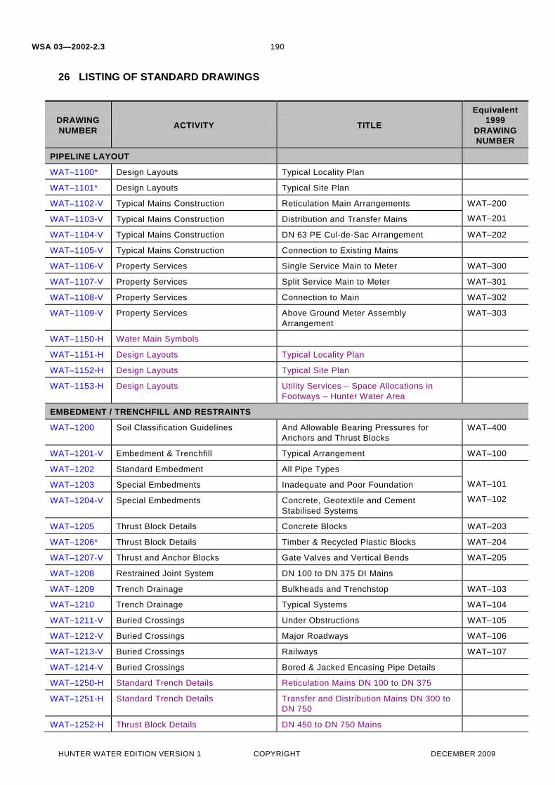
26 LISTING OF STANDARD DRAWINGS
DRAWING NUMBER ACTIVITY TITLE
Equivalent 1999
DRAWING NUMBER
PIPELINE LAYOUT
WAT–1100* Design Layouts Typical Locality Plan
WAT–1101* Design Layouts Typical Site Plan
WAT–1102-V Typical Mains Construction Reticulation Main Arrangements WAT–200
WAT–201 WAT–1103-V Typical Mains Construction Distribution and Transfer Mains
WAT–1104-V Typical Mains Construction DN 63 PE Cul-de-Sac Arrangement WAT–202
WAT–1105-V Typical Mains Construction Connection to Existing Mains
WAT–1106-V Property Services Single Service Main to Meter WAT–300
WAT–1107-V Property Services Split Service Main to Meter WAT–301
WAT–1108-V Property Services Connection to Main WAT–302
WAT–1109-V Property Services Above Ground Meter Assembly Arrangement
WAT–303
WAT–1150-H Water Main Symbols
WAT–1151-H Design Layouts Typical Locality Plan
WAT–1152-H Design Layouts Typical Site Plan
WAT–1153-H Design Layouts Utility Services – Space Allocations in Footways – Hunter Water Area
EMBEDMENT / TRENCHFILL AND RESTRAINTS
WAT–1200 Soil Classification Guidelines And Allowable Bearing Pressures for Anchors and Thrust Blocks
WAT–400
WAT–1201-V Embedment & Trenchfill Typical Arrangement WAT–100
WAT–1202 Standard Embedment All Pipe Types
WAT–101
WAT–102
WAT–1203 Special Embedments Inadequate and Poor Foundation
WAT–1204-V Special Embedments Concrete, Geotextile and Cement Stabilised Systems
WAT–1205 Thrust Block Details Concrete Blocks WAT–203
WAT–1206* Thrust Block Details Timber & Recycled Plastic Blocks WAT–204
WAT–1207-V Thrust and Anchor Blocks Gate Valves and Vertical Bends WAT–205
WAT–1208 Restrained Joint System DN 100 to DN 375 DI Mains
WAT–1209 Trench Drainage Bulkheads and Trenchstop WAT–103
WAT–1210 Trench Drainage Typical Systems WAT–104
WAT–1211-V Buried Crossings Under Obstructions WAT–105
WAT–1212-V Buried Crossings Major Roadways WAT–106
WAT–1213-V Buried Crossings Railways WAT–107
WAT–1214-V Buried Crossings Bored & Jacked Encasing Pipe Details
WAT–1250-H Standard Trench Details Reticulation Mains DN 100 to DN 375
WAT–1251-H Standard Trench Details Transfer and Distribution Mains DN 300 to DN 750
WAT–1252-H Thrust Block Details DN 450 to DN 750 Mains

WSA 03—2002-2.3
HUNTER WATER EDITION VERSION 1 COPYRIGHT DECEMBER 2009
191
DRAWING NUMBER ACTIVITY TITLE
Equivalent 1999
DRAWING NUMBER
EMBEDMENT / TRENCHFILL AND RESTRAINTS continued
WAT–1253-H Anchorage Details Stop Valve Installations up to DN 1200 SCL Mains
WAT–1254-H Anchorage Details Stop Valve Installations up to DN 750 DICL Mains
WAT–1255-H Buried Crossings Under Minor Obstructions
INSTALLATION PRACTICES/ STRUCTURES
WAT–1300-V Valve and Hydrant Identification Identification Markers & Marker Posts WAT–207
WAT–1301-V Typical Valve & Hydrant Installation Valve Arrangement WAT–206
WAT–1302-V Typical Valve & Hydrant Installation Hydrants and Air Relief Valves WAT–206
WAT–210
WAT–1303-V Typical Surface Fitting Installation Gate Valve Surface Boxes Non Trafficable
WAT–208
WAT–209
WAT–1304-V Typical Surface Fitting Installation Gate Valve Surface Boxes Trafficable
WAT–1305-V Typical Surface Fitting Installation Hydrant Surface Boxes Trafficable and Non Trafficable
WAT–1306-V Typical Surface Fitting Installation Hydrant Surface Boxes Trafficable
WAT–1307-V Typical Appurtenance Installation Scour Arrangements WAT–211
WAT–1308-V Typical Appurtenance Installation Valve Chambers
WAT–1309-V Typical Appurtenance Installation Pressure Reducing Valves (PRV) WAT–213
WAT–1310-V Aerial Crossings Aqueduct WAT–108
WAT–1311 Aerial Crossings Aqueduct Protection Grille WAT–109
WAT–1312 Aerial Crossings Bridge Crossing Concepts
WAT–1313 Flanged Joints Bolting Details
WAT–1350-H Typical Appurtenance Installation Valve Gearbox Chamber for Vertical Type Gate Valve & Bypass in Footway
WAT–1351-H Typical Appurtenance Installation Valve Gearbox Chamber for Vertical Type Gate Valve & Bypass in Carriageway
WAT–1355-H Aerial Crossings Circular RC Piers in Non Flood Conditions for DN 100 to DN 750 Mains
FABRICATION DETAILS
WAT–1400 Typical Steel Pipe Jointing Butt Welding of Joints
WAT–1401-V Typical Steel Pipe Jointing Rubber Ring Joint Spigot Bands
WAT–1402 Typical Steel Pipe Jointing Welded Pipe Collars
WAT–1403 Typical Steel Fabrication Bends
WAT–1404 Typical Steel Fabrication Access Opening for Pipes ≥DN 750
WAT–1405 Typical Steel Fabrication Dismantling and Flexible Joints
WAT–1406-V Typical Steel Fabrication Valve Connection & Bypass
WAT–1407-V DI Installation Valve Bypass Arrangement DI and GRP Pipe
WAT–1408-V Joint Corrosion Protection Cement Mortar Lined Steel Pipe DN 300 to DN 1200
FABRICATION DETAILS continued
WSA 03—2002-2.3
HUNTER WATER EDITION VERSION 1 COPYRIGHT DECEMBER 2009
192
DRAWING NUMBER ACTIVITY TITLE
Equivalent 1999
DRAWING NUMBER
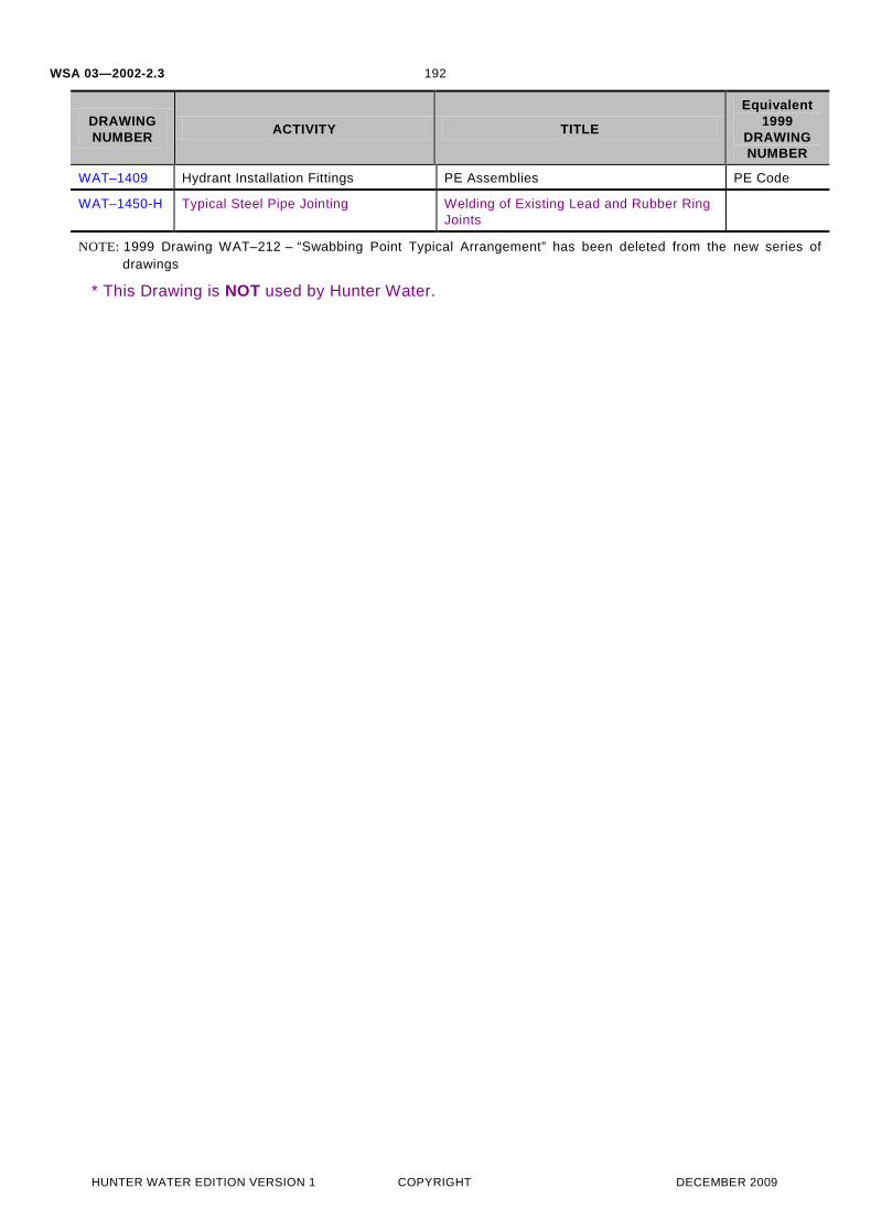
WAT–1409 Hydrant Installation Fittings PE Assemblies PE Code
WAT–1450-H Typical Steel Pipe Jointing Welding of Existing Lead and Rubber Ring Joints
NOTE: 1999 Drawing WAT–212 – “Swabbing Point Typical Arrangement” has been deleted from the new series of drawings
* This Drawing is NOT used by Hunter Water.