Embed Size (px)
Citation preview

Start-Up, Maintenance, and Troubleshooting of AdvanTex® AX-Max™ and AX-Mobile™
Wastewater Treatment Systems
COMMERCIAL
O&MManual
®
800-348-9843+1 (541) 459-4449www.orenco.comwww.vericomm.net
Orenco SystemsIncorporated
Changing the Way theWorld Does Wastewater®
advanTex® O&M ManualA X - M A X ™ A n d A X - M o B I L E ™ T R E A T M E n T S Y S T E M S

2AIM-OM-ATX-4, Rev. 1.0, 11/11 • Copyright Orenco Systems®, Inc. Property of Orenco Systems®, Inc. Do not reproduce or distribute without written authorization from Orenco: 800-348-9843.
advanTex® O&M ManualA X - M A X ™ A n d A X - M o B I L E ™ T R E A T M E n T S Y S T E M S
About OrencoSince 1981, Orenco Systems®, Inc. has researched, designed, and manufactured leading-edge decentralized wastewater treatment technologies. We are one of the nation’s leading manufacturers and suppliers of equipment for the collection and treatment of wastewater. At Orenco, we specialize in the manufacture of complete treatment systems for residential, commercial and community applications. Wastewater collection and treatment is our only job. When you purchase an Orenco system, you can be confident you have chosen the best equipment available.
AssistanceIn addition to providing quality equipment, Orenco prides itself on its outstanding customer service and technical assistance. Should you have any questions regarding your system, components, instructions, or this O&M Manual, please contact us for assistance. Please include the name and location of your project or system with any correspondence, so we can quickly respond to your request.
When Your Equipment ArrivesInspect your order for completeness and inspect each component for shipping damage. Check to be sure that the instructions and items supplied comply with your state and local regulations. Carefully read and follow all instructions. Be aware that improper system or component installation may void warranties.
System OperatorsTo get the most from your Commercial AdvanTex Treatment System, we recommend that operation and maintenance functions be performed by an operator trained by Orenco on AdvanTex Treatment Systems. If you do not have a trained operator for your system or you would like more information on Orenco’s operator training, please contact Orenco at (800) 348 -9843 or +1 (541) 459-4449. Or visit us at our Web site: www.orenco.com/systems/.
Introduction

3Copyright Orenco Systems®, Inc. Property of Orenco Systems®, Inc. Do not reproduce or distribute without written authorization from Orenco: 800-348-9843. • AIM-OM-ATX-4, Rev. 1.0, 11/11
advanTex® O&M ManualA X - M A X ™ A n d A X - M o B I L E ™ T R E A T M E n T S Y S T E M S
Table of Contents
Introduction About Orenco® .............................................................................. 2
Assistance ..................................................................................... 2
When Your Equipment Arrives ...................................................... 2
System Operators ......................................................................... 2
About the AdvanTex® AX-Max™ and AX-Mobile™ Treatment Systems Primary Tankage ........................................................................... 4
Equalization Tankage .................................................................... 4
Anoxic Tankage ............................................................................. 4
Treatment Units ............................................................................. 4
Second-Stage Units ...................................................................... 5
Start-Up & Operation Introduction ................................................................................... 6
Roles and Responsibilities ............................................................ 6
Safety Precautions ........................................................................ 6
Recommended Tools and Equipment ........................................... 6
Pre-Start-Up Inspection Points ..................................................... 7
Start-Up & Operation Inspection Points and Steps ..................... 7
Control Panels ........................................................................... 7
Primary Tanks ........................................................................... 8
Equalization Tanks .................................................................. 10
Pump Operation for Primary and Equalization Tanks ............ 10
Pump Amperage Chart ........................................................... 11
Tank Timer Settings ................................................................ 12
AdvanTex® Treatment Units .................................................... 12
Housekeeping ............................................................................. 14
Maintenance Record Keeping ........................................................................... 15
Tools, Equipment, and Spare Parts ............................................. 15
Routine Inspection and Maintenance .................................... 15
Repairs .................................................................................... 15
Personal Hygiene and Cleanup .............................................. 15
Preventive Maintenance ............................................................. 16
Scheduled Maintenance ............................................................. 16
Scheduled Maintenance Reference Chart ............................. 16
Monthly Maintenance ............................................................. 17
Quarterly Maintenance ........................................................... 17
Semi-Annual Maintenance ..................................................... 17
Annual Maintenance ............................................................... 18
Biennial Maintenance ............................................................. 18
Corrective Maintenance .............................................................. 19
High Liquid Level Alarm .......................................................... 19
Low Liquid Level Alarm .......................................................... 20
Removing & Replacing Inoperative Floats ............................. 20
Removing & Replacing Inoperative Pumps ............................ 20
System Performance and Nitrogen Reduction Process System Performance .................................................................. 21
Nitrogen Reduction Process ....................................................... 21
Signs of Effective Nitrogen Reduction ................................... 22
Performance Indicators of Nitrogen Reduction ..................... 22
Troubleshooting Effluent Quality Troubleshooting Effluent Quality ................................................. 23
Poor Effluent Quality ................................................................... 23
Odor ............................................................................................. 23
Effluent Filter or Biotube® Filter Clogging .................................. 23
Oily Film ....................................................................................... 23
Foam ............................................................................................ 23
Troubleshooting Nitrogen Reduction Troubleshooting Nitrogen Reduction .......................................... 24
Notes .....................................................26
O&M Binder Appendices Warranty and Materials List .......................................................... A
Installation Instructions and Field Maintenance Report Form ................................................... B
Submittals and Technical Data Sheets ......................................... C
Pump Repair Manual ....................................................................D
Automatic Distributing Valve Manual and Booklet ....................... E
Control Panel ................................................................................. F
Material Specifications ................................................................. G
Design Criteria ...............................................................................H

4AIM-OM-ATX-4, Rev. 1.0, 11/11 • Copyright Orenco Systems®, Inc. Property of Orenco Systems®, Inc. Do not reproduce or distribute without written authorization from Orenco: 800-348-9843.
advanTex® O&M ManualA X - M A X ™ A n d A X - M o B I L E ™ T R E A T M E n T S Y S T E M S
About AdvanTex® AX-Max™ and AX-Mobile™ Treatment Systems
Primary TankageThe primary tank is an enclosed, watertight receptacle designed to collect wastewater; segregate settleable and floatable solids (sludge and scum); accumulate, consolidate, and store solids; digest organic matter; and discharge treated effluent.
In the primary tank, wastewater separates into three distinct layers: a floating scum layer, a bottom sludge layer, and a clear zone in between, which is relatively free of large solids. BOD (biochemical oxygen demand) removals of greater than 65 percent and TSS (total suspended solids) removals of greater than 70 percent are easily accomplished by the passive treatment provided in the primary tank. An effluent filter or pump vault allows liquid effluent from the clear zone to be transported to the next step in the treatment process.
A typical treatment system with AdvanTex® AX-Max or AX-Mobile Treatment Units uses one or more Orenco® T-Max™ primary tanks in parallel or series, depending on the size of the system, to provide passive primary wastewater treatment. Then the liquid effluent is transported to the recirculation/blend chamber of the AX-Max or AX-Mobile unit, either by gravity through an effluent filter or by pump, through a pump vault. Depending on the system configuration, the primary tank may be preceded by a grease interceptor tank. For some AX-Mobile applications, primary tankage is incorporated right into the treatment unit.
Equalization Tankage (if applicable)Equalization tanks are used in systems with large surge volumes or great variability in daily, weekly, or monthly flows. Their design and operation are generally similar to that of primary tanks and they generally contain similar components as well.
Anoxic TankageIn some cases, an anoxic (low oxygen) tank may be required for enhanced denitrification. The anoxic tank enhances the denitrification of AdvanTex® filtrate. It is sized based on the design flow of the system and can be located before or after (pre-anoxic or post-anoxic) AdvanTex treatment in the treatment train.
The anoxic tank provides an ideal environment for carbonaceous microbes to reduce nitrate to nitrogen gas (denitrification) in the AdvanTex filtrate returning from the treatment unit. The harmless nitrogen gas is released freely back into the atmosphere.
Treatment UnitsThe AdvanTex AX-Max™ and AX-Mobile™ Treatment Units are a multiple-pass, packed-bed, aerobic wastewater treatment technology specifically designed and engineered for processing of domestic-strength wastewater to “better than secondary” treatment standards. Typical unit configurations for AX-Max and AX-Mobile units include a recirc/blend chamber, a recirc/filtrate chamber, and an AdvanTex textile media filter.
The AdvanTex textile media filter is located above the recirc/blend chamber
and recirc-filtrate chamber. A timer-controlled pump applies blended effluent from the recirc/blend chamber onto the AdvanTex filter media. The filtered effluent percolates down through the media and into the recirc/blend chamber and recirc/filtrate chamber. This design reduces the waste strength applied to the AdvanTex filter by mixing primary-treated effluent with AdvanTex filtrate.
Clear zone
Sludge layer
Scum layer

5Copyright Orenco Systems®, Inc. Property of Orenco Systems®, Inc. Do not reproduce or distribute without written authorization from Orenco: 800-348-9843. • AIM-OM-ATX-4, Rev. 1.0, 11/11
advanTex® O&M ManualA X - M A X ™ A n d A X - M o B I L E ™ T R E A T M E n T S Y S T E M S
About the AdvanTex AX-Max and AX-Mobile Treatment Systems
1
2
5
13
3
7
15
17
6
14
4
12
8
16
18
199
10
11
Standard Components (AX-MAX125-21 shown):Inlet, not shown1
Recirc-blend chamber2
Tank baffle3
Recirc-transfer line4
Recirc-pump chamber baffle5
Spray nozzles9
Lateral ball valves10
6 Recirc-pump chamber
Distribution manifold8
7 Recirc pumping assemblies11 AdvanTex textile media12 Recirc-return valve13 Recirc-filtrate chamber14 Discharge pumping assembly15 Outlet, discharge
16 Vent fan assembly17 Air inlet18 Air outlet19 Hinged lid, typical
AX-Max and AX-Mobile Secondary Treatment Unit Components: Typical Configuration
The textile media has a large surface area and void volume for free flow of oxygen. Wastewater percolates both through and between the textile media. A visible biological film normally develops on the filter media within a few days of the system start-up. Inside the filter, aerobic conditions exist that are ideal for immediate biological reductions in BOD and TSS. Microbes for nitrification (the process of converting ammonia to nitrates) also begin to develop in the filter within four to six weeks, depending on temperature. Warmer temperatures will help nitrifying bacteria to develop sooner. The nitrification process will depend on temperature and alkalinity.
After percolating through the media, the filtrate is then distributed into both the recirc/blend chamber and the recirc/filtrate chamber. As it fills the recirc/filtrate chamber, the effluent is either allowed to flow back into the recirc/blend chamber (during low flow conditions) or discharged to tertiary treatment or final dispersal.
Second-Stage UnitsSecond-stage AX-Max and AX-Mobile units are used in systems requiring advanced ammonia removal or polishing after a post-anoxic denitrification process. Their design and operation are the same as other AX-Max and AX-Mobile units.

6AIM-OM-ATX-4, Rev. 1.0, 11/11 • Copyright Orenco Systems®, Inc. Property of Orenco Systems®, Inc. Do not reproduce or distribute without written authorization from Orenco: 800-348-9843.
advanTex® O&M ManualA X - M A X ™ A n d A X - M o B I L E ™ T R E A T M E n T S Y S T E M S
Start-up & Operation
IntroductionThis section covers the start-up of an AdvanTex® AX-Max or AX-Mobile Treatment System in a commercial application. The formal start-up of an AdvanTex Treatment System should only be performed by trained personnel. As a trained member of the team performing the system start-up, you play a critical role in the operation of the system. The decisions made at the time of the start-up will determine the long-term maintenance needs of the system. Regulators, manufacturers, dealers, property owners, neighbors, and service providers all rely on a thorough start-up.
Before you start up the system, please read this entire manual, as well as the engineering plans, and contact your Dealer if you have any questions. You’ll save yourself time and money, and you’ll reduce the potential for follow-up work. For information specific to your system, refer to your detailed engineering plans.
We recommend following the flow path through the treatment train, if possible, when performing the system start-up, beginning at the building outlets and ending at the final discharge point. By following this start-up sequence, the treatment train can be effectively inspected for proper operation and each step in the process can be given systematic attention.
Roles and ResponsibilitiesPrior to start-up, the Orenco Representative or AdvanTex Dealer will contact the Designer, Installer, and Service Provider to coordinate a start-up date. The date will be based on a status report provided by the Orenco Representative and the availability of all parties. The status report will include, but will not be limited to, verification of leak testing performed by the Installer, installation of all equipment, and the availability of power, phone line, and water at the site.
The • AdvanTex Dealer is expected to be on site and is either performing the start-up or acting as a coordinator and general resource during the installation and start-up of the system.
The • Designer is required at the site during start-up to answer questions concerning site-specific issues not covered in the plans, timer settings, and float switch settings.
The • Installer is required at the site during start-up to address any installation issues that arise.
The • Service Provider is required at the site during start-up to become familiar with the system, receive training on control panel and treatment system operation, and to learn correct sampling techniques for the system.
Safety PrecautionsBefore starting up, maintaining, or servicing any wastewater treatment system, observe the following precautions for the safety and health of all service personnel working with or around wastewater, effluent, and its associated equipment:
Wear proper clothing that covers all parts of the body that will be • exposed to wastewater or effluent.
Wear personal protection equipment (PPE) such as rubber gloves and • eye protection when handling or touching any equipment components that come in contact with wastewater or effluent.
Turn off system power at the service entrance panel and set the circuit • breakers in the panel to their “OFF” positions before removing any system components. Use Lock Out/Tag Out tags to ensure safety.
Avoid driving over any part of the wastewater treatment system unless • it’s been equipped to withstand vehicle traffic. If the system is subject to possible traffic, put a barricade up to protect the system.
Take necessary precautions to avoid falling into AX-Max or AX-Mobile • units.
Do not enter any tank access. Any work performed on the tank should • be done from the outside. Gases and/or oxygen depletion in the tank can be fatal.
Properly secure all access lids after all work is complete.•
Practice proper personal hygiene at all times.•
Recommended Tools and Equipment: Start-UpThe following items are recommended for a smooth, successful start-up:
A tool kit containing common tools and these additional items: •
A cordless power drill with ½-in. nut driver and ½-in. hex-head bit –
Voltmeter –
Small electronics screwdrivers –
Wire strippers/cutters –
Cable ties –
Tape measure –
Adjustable pliers –
A laptop computer with Hyperterminal (PC) or ZTERM (MAC), to • interface with the control panel if the control panel doesn’t have a touch screen.
A copy of the layout and a start-up checklist for the person • performing the system start-up.
Appropriate personal protection equipment (PPE) for each person • involved in the start-up.

7Copyright Orenco Systems®, Inc. Property of Orenco Systems®, Inc. Do not reproduce or distribute without written authorization from Orenco: 800-348-9843. • AIM-OM-ATX-4, Rev. 1.0, 11/11
advanTex® O&M ManualA X - M A X ™ A n d A X - M o B I L E ™ T R E A T M E n T S Y S T E M S
Control PanelsThe system may have multiple control panels. For AX-Mobile Treatment Units, control panels are typically built into the treatment unit. Identify if there are control panels on the section of the system that you are about to start up and perform the following start-up steps:
1. Panel documentation: Locate the panel-wiring diagram inside the panel and verify the document matches the document number found on the inside of the front panel door. If you can’t find the wiring
diagram, contact Orenco at (800) 348-9843 or (541) 459-4449 to have a copy e-mailed or faxed to you.
2. Wiring installation: Verify all of the main breakers are in the “OFF” position. Inspect the wire terminations in the panel by giving a light tug to all of the float switch wires, pump wires, pump power lines, and main power lines in the panel. If a wire comes loose, reattach the wire correctly.
WARNING: Loose wires can cause intermittent failures, inconsistent panel operation, and over-current conditions on pumps.
3. Conduit seal installation: Check for conduit seals on all conduit connections to the control panel.
WARNING: Failing to seal the conduit may allow corrosive gasses to corrode major components. Orenco recommends conduit seals for all connections to the control panel to assure proper system operation and component longevity.
Pre-Start-Up Inspection PointsSystem layout: • Verify that the component layout in the plans or the system diagram matches the installed system and note any differences between the plans and the installed system.
Site drainage: • Verify that all riser lids, external splice box lids, and treatment unit lids are level and above grade. Verify that the soil slopes away from all lids for good drainage.
Serviceability: • Verify that there is sufficient space between treatment units to fully open the lids on the treatment units. Check for a useable water source within hose distance of the system.
Landscaping: • Check for landscape features that may cause maintenance issues:
Trees planted near tanks or on top of tanks –
Trees that could shed snow onto critical components, such as –control panels
Risers, external splice boxes, and components covered in bark or –other landscaping materials
Circuit breakers: •Open the control panel and make sure that all of the circuit breakers are switched to “Off.”
System access: •Remove lid bolts and open all lids.
AX-Max or •AX-Mobile: Verify that all of the shipping materials are removed from the treatment units. If not, remove them at this time. Verify that the lateral inlet valves in the pods are open and the spray nozzle turbines are pointed up.
Pre-Start-Up Inspection Points
Start-Up & Operation — Inspection Points and Steps
Panel documentation
Document number

8AIM-OM-ATX-4, Rev. 1.0, 11/11 • Copyright Orenco Systems®, Inc. Property of Orenco Systems®, Inc. Do not reproduce or distribute without written authorization from Orenco: 800-348-9843.
advanTex® O&M ManualA X - M A X ™ A n d A X - M o B I L E ™ T R E A T M E n T S Y S T E M S
4. Power supply voltage: Make sure the panel breakers are switched off, and check the power supply voltage at the panel.
On 120 V panels, measure voltage between L1 and neutral. The • voltage should be within ten percent of nominal.
On 230 V panels, measure the voltage between L1 and neutral, • and between L2 and neutral. The voltage of each leg should be approximately 115 volts. Measure the voltage between L1 and L2. The voltage should be within ten percent of nominal.
On 208 V, 230 V, and 460 V 3-phase panels, measure the voltage • between L1 & L2, L2 & L3, and L3 & L1. The voltage between each leg should be 208, 230 or 460 volts, respectively. If there is a voltage difference between line legs, it is an indication that the power source may be undersized. The voltage between each leg and ground on 208 volts should be approximately 120 volts. The voltage between each leg and ground on 460 volts should be approximately 277 volts. (Due to the variability in the ways 230 V, 3-phase power can be wired, there is not a standard test method.)
5. Neutral and ground voltage: Check for any voltage difference between each neutral (N) wire in the panel and ground. If there is a difference in voltage, use the wiring diagram to track down the source of the difference and correct it.
6. Controls circuit: Connect the controls circuit if it is not already connected. The controls circuit is now ready to be turned on. Do not turn on the pump circuit at this time.
WARNING: Turning the pump circuit on at this time can damage the panel or the pump if the pumps and floats are miswired or if there isn’t sufficient liquid in the tank.
7. Panel operation: Verify that the panel is powered up.
On TCOM panels, an LED will light up indicating the board is • operational. If the blinking light does not turn on, refer to the wiring diagram and verify the connections on the control circuit were properly terminated.
On MVP, Simplex, and Duplex panels, turn on the control circuit, • then toggle the pump “AUTO-OFF-MAN” switch to “MAN.” The motor contactor will visibly and audibly engage at this point. If the motor contactor does not engage and there are no alarm conditions, refer to the wiring diagram and verify the connections on the control circuit were properly terminated.
Primary TanksThe ability to easily remove filters and float switch assemblies from primary tanks is essential. Check the system plans to identify any associated components, such as splice boxes, float switches, filters, or pump vaults. Primary tanks may not have associated components as described below. Place system components on a plastic tarp or sheeting when they are out of the tank. Record inspection results on the Field Maintenance Report Form.
1. Tanks: Confirm with the installer that all tanks have antibuoyancy measures installed (if necessary) and that they have passed watertightness testing. Verify that the inlet and outlet of the tank and riser(s) are properly installed.
2. Risers: Inspect riser attachments and rubber grommets for a watertight seal.
3. Splice boxes: Inspect all splice boxes for correct wiring and the use of waterproof splice nuts. If there is water in a splice box, use a suction bulb or sponge to remove the water.
WARNING: Failure to use waterproof wire nuts can cause intermittent or permanent float switch failure.
4. Float switch assemblies: If the tank is equipped with a float switch assembly, verify that it is easy to remove for service and maintenance. Also verify the float switch settings.
a. Detach the float switch assembly from the bracket on the effluent filter or pump vault, remove it from the tank, and lay it aside. Verify there is enough slack in the cord for easy removal.
Start-Up and Operation — Inspection Points and Steps
Blinking LED

9Copyright Orenco Systems®, Inc. Property of Orenco Systems®, Inc. Do not reproduce or distribute without written authorization from Orenco: 800-348-9843. • AIM-OM-ATX-4, Rev. 1.0, 11/11
advanTex® O&M ManualA X - M A X ™ A n d A X - M o B I L E ™ T R E A T M E n T S Y S T E M S
b. Raise the high-level alarm float switch to simulate a high-level condition. Verify that the high-level signal is on by the audible alarm or the high-level alarm input LED on the circuit board in the panel.
NOTE: The audible alarm is delayed for 2 hours in TCOM control panels.
c. When the assembly is out of the tank, verify the handle is long enough for easy access. If not, adjust it to the necessary length.
d. Check the float switch settings provided in the plans against the actual float switch settings. If the plans don’t provide float switch settings and the engineer or system designer is unable to provide settings, set the float switches based on the following general float switch setting rules:
Demand Dose:•
“Redundant Off” (RO) –float switch is set 3 inches (76 mm) above filter cartridge or minimum liquid level of the pump, whichever is higher.
“Pump Off” float switch –is set 3 inches (50 mm) above “RO” float switch or for a minimum 30-second drawdown differential between the “Pump Off” float switch and “RO” float switch.
To calculate distance –between “Pump On” and “Pump Off” float switches, divide desired dose volume by the gallons per inch (or liters per mm) of the tank. Place the “Pump On” float switch that many inches (or mm) above the “Pump Off” float switch.
“High Level” or “High Level/Lag Pump Enable” float switch is –set at 2 inches (50 mm) below invert of tank inlet.
WARNING: Pumps have a 30-second minimum run time. If the drawdown differential between the “Pump Off” float switch and “RO” float switch is less then 30 seconds, the pumps may continue to run, resulting in a false low-level alarm.
Timed Dose: •
“RO” float switch is set –3 inches (76 mm) above the filter cartridge.
“Timer On/Off” float –switch is set 3 inches (50 mm) above the “RO” float switch.
“Override Timer” float –switch is set 3 inches (76 mm) below the “High Level” float switch switch.
“High Level” or “High –Level/Lag Pump Enable” float switch is set at 2 inches (50 mm) below the invert of the tank inlet.
NOTE: If you use the general float switch setting rules, you may need to return at a later time after the system is in operation and adjust float switch settings.
e. Leave the float switch assembly out of the tank for use during pump run testing.
5. Effluent filters: If the tank is equipped with an effluent filter, verify that the filter cartridge is easy to remove for service and maintenance.
a. Pull the effluent filter cartridge out of the housing and remove it from the tank. There should be ample clearance to allow easy removal of the cartridge from the housing and tank.
b. When the cartridge is out of the tank, verify that the handle is long enough for easy access. If not, adjust it to the necessary length.
c. Reinstall the cartridge into the effluent filter housing.
Start-Up and Operation — Inspection Points and Steps
2"50 mm
3"76 mm
Invert oftank inlet
Filter cartridgeor minimumliquid level
Float Configuation,Timed Dose
3"76 mm
3"76 mm
RO
Timer On/Off
Override Timer
High Level
2"(50 mm)
Invert oftank inlet
Filter cartridgeor minimumliquid level
Float Configuration, Demand Dose
3" (76 mm) or 30-second drawdown
Calculate distance
Calculate distance
3"(76 mm)
RO
Pump Off
Pump On
High Level/Lag Pump Enable

10AIM-OM-ATX-4, Rev. 1.0, 11/11 • Copyright Orenco Systems®, Inc. Property of Orenco Systems®, Inc. Do not reproduce or distribute without written authorization from Orenco: 800-348-9843.
advanTex® O&M ManualA X - M A X ™ A n d A X - M o B I L E ™ T R E A T M E n T S Y S T E M S
6. Biotube® pump vault filter: If the tank is equipped with a Biotube pump vault filter, verify the pump vault filter cartridge is easy to remove for service and maintenance.
a. Pull the filter cartridge out of the pump vault and remove it from the tank. There should be ample clearance to allow easy removal of the cartridge from the pump vault and tank.
b. When the cartridge is out of the tank, verify that the handle is long enough for easy access. If not, adjust it to the necessary length.
f. Reinstall the cartridge in the pump vault.
7. Effluent pump access: If the primary tank is equipped with an effluent pump, verify that the pump is easy to remove for service and maintenance and that the pump flow rate and voltage are correct.
a. Verify that the ball valve and cam-lock fitting or union on the discharge assembly is within 24 in. (610 mm) of the top of the tank riser.
b. Close the ball valve on the discharge assembly if there is one and disconnect the discharge assembly at the cam-lock fitting or union.
c. Verify that there is enough slack in the pump cord for easy removal.
d. Pull the pump out of the vault by the discharge assembly and remove the pump from the tank.
WARNING: Lifting or lowering the pump by the cord can damage the pump and cord.
e. Check the voltage and phase values on the pump nameplate. Write them down in the start-up report. If there are pump motor stickers on the inside of the control panel door, check to see if they match the pump nameplate.
WARNING: If the pump does not match the panel voltage and phase requirements, do not turn on the pump breakers!
f. Reinstall the pump if the pump matches the panel voltage and phase requirements.
g. Reconnect the discharge assembly at the union or cam-lock fitting and open the discharge assembly ball valve.
Equalization TanksThe ability to easily remove filters and float switch assemblies from equalization tanks is essential. Equalization tanks typically contain components similar to primary tanks. Check the system plans to identify any associated components, such as splice boxes, float switches, filters, or pump vaults and follow the steps listed for these components from the section on start-up and inspection points for primary tanks. Record inspection results on the Field Maintenance Report Form.
Pump Operation for Primary and Equalization TanksAfter the necessary control panels are inspected and powered up, the float switch inputs have been tested, and all pump voltage and phase information has been verified, primary tank pump(s) and equalization tank pump(s) can be powered up and tested. Record all necessary information on the Field Maintenance Report Form.
1. Manual pump operation:
a. Turn the effluent pump breaker(s) in the control panel to the “ON” position.
b. Measure the static voltage of the pump(s) and enter the value(s) on the start-up checklist.
c. Toggle the pump “AUTO-OFF-MAN” switch to “MAN.” The motor contactor will visibly and audibly engage at this point. If the motor contactor does not engage, check for an “RO” alarm condition. If there is no alarm condition, refer to the wiring diagram and verify that the connections on the control circuit were properly terminated.
WARNING: There is no motor protection in TCOM panels and panels without “RO” alarms. Before running a pump, always verify that there is sufficient liquid in the tank.
d. Check the discharge plumbing assembly (DPA) for vibration to verify the pump motor is operating.
No vibration in the DPA indicates a pump wiring issue. Check the –pump voltage and pump wiring terminations in the panel and in the splice box. Wires may be incorrectly terminated or wire insulation may be causing faulty contact between the wire and terminal lug.
Vibration in the DPA with low or no flow from the pump –indicates closed valves or line breakages. On duplex pumping systems where two DPAs are plumbed together in a single
Start-Up and Operation — Inspection Points and Steps
11Copyright Orenco Systems®, Inc. Property of Orenco Systems®, Inc. Do not reproduce or distribute without written authorization from Orenco: 800-348-9843. • AIM-OM-ATX-4, Rev. 1.0, 11/11
advanTex® O&M ManualA X - M A X ™ A n d A X - M o B I L E ™ T R E A T M E n T S Y S T E M S
Start-Up and Operation — Inspection Points and Steps
Pump Model Low Amp Reading High Amp Reading Pump Model Low Amp Reading High Amp ReadingPF100511 11.9 12.6 PF30503200 15.4 18.6PF100512 6.0 6.4 PF500511 10.5 12.1PF10053200 3.5 3.9 PF500512 5.4 6.2PF100552 3.6 3.8 PF500532 2.6 3.0PF100712 7.8 8.4 PF50053200 3.2 3.7PF10073200 4.9 5.2 PF500534 1.3 1.5PF100752 5.8 6.2 PF500552 3.3 3.9PF101012 9.0 9.8 PF500712 7.3 8.5PF10103200 5.1 5.6 PF500732 3.1 3.9PF101552 9.4 11.4 PF50073200 3.9 4.9PF102012 10.0 12.2 PF500734 1.4 1.8PF102032 6.4 7.6 PF501012 8.8 10.1PF10203200 7.5 8.7 PF50103200 4.6 5.7PF200511 11.0 12.5 PF501034 1.8 2.2PF200512 5.8 6.5 PF501512 9.6 12.6PF200532 2.5 2.9 PF50153200 5.4 7.0PF20053200 3.3 3.8 PF501552 8.0 9.1PF201012 9.6 10.5 PF503012 12.6 17.7PF300511 10.7 11.8 PF503032 8 10.4PF20103200 5.0 5.9 PF50303200 10.1 13.1PF20153200 6.0 7.2 PF503034 4.2 5.3PF201512 10.5 12.6 PF505012 17.3 26.4PF300512 5.6 6.2 PF505032 13.1 16.5PF30053200 3.3 3.7 PF751512 11.4 12.3PF300552 3.5 4.2PF300712 7.4 8.6 P200511 12.6 13.8PF300752 5.5 6.1 P200512 6.1 7.1PF30073200 4.1 4.9 P201512 11.2 12.2PF301012 9.3 10.4 P300512 5.8 6.5PF301052 6.4 7.4 P300712 7.4 8.3PF30103200 4.9 5.8 P301012 9.1 10.3PF301512 10.1 12.6 P500511 11.2 12.7PF30153200 5.5 6.9 P500512 5.8 6.5PF301534 2.3 2.8 P50053200 3.4 3.8PF301552 8.1 9.3 P500712 7.7 8.8PF302012 7.4 11.0 P50073200 3.8 4.8PF30203200 7.7 9.3 P501012 9.4 11.2PF303012 12.6 16.8 P501512 10.6 13.1PF303032 8.2 10.1 P50153200 6.0 7.6PF305012 20.1 25.8PF305032 14.0 16.6 PEF3311 6.9 7.8
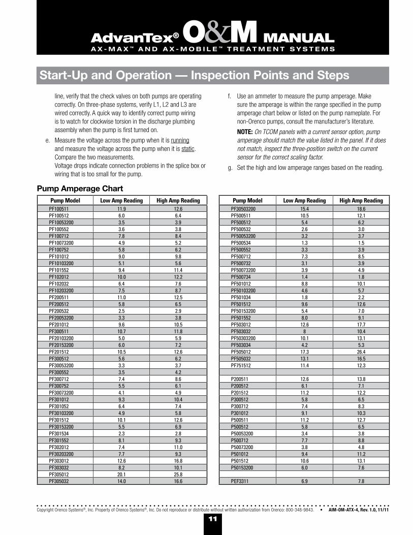
Pump Amperage Chart
line, verify that the check valves on both pumps are operating correctly. On three-phase systems, verify L1, L2 and L3 are wired correctly. A quick way to identify correct pump wiring is to watch for clockwise torsion in the discharge plumbing assembly when the pump is first turned on.
e. Measure the voltage across the pump when it is running and measure the voltage across the pump when it is static. Compare the two measurements. Voltage drops indicate connection problems in the splice box or wiring that is too small for the pump.
f. Use an ammeter to measure the pump amperage. Make sure the amperage is within the range specified in the pump amperage chart below or listed on the pump nameplate. For non-Orenco pumps, consult the manufacturer’s literature.
NOTE: On TCOM panels with a current sensor option, pump amperage should match the value listed in the panel. If it does not match, inspect the three-position switch on the current sensor for the correct scaling factor.
g. Set the high and low amperage ranges based on the reading.

12AIM-OM-ATX-4, Rev. 1.0, 11/11 • Copyright Orenco Systems®, Inc. Property of Orenco Systems®, Inc. Do not reproduce or distribute without written authorization from Orenco: 800-348-9843.
advanTex® O&M ManualA X - M A X ™ A n d A X - M o B I L E ™ T R E A T M E n T S Y S T E M S
2. Automatic pump operation: Test the system by using the float switches to drive pump operation.
Demand dose• :
a. Toggle the “AUTO-OFF-MAN” switch to the “AUTO” position.
b. Unclip the float switch assembly and remove it from the tank if it is not out already.
c. Verify the automatic operation of the pumps by incrementally lifting the float switches to simulate normal raising and lowering of the tank liquid level. The pumps should cycle on when you lift them and cycle off when you release them. On duplex systems, the pumps should alternate between lead and lag pumps and cycle off when the float switches are dropped.
NOTE: An “On/Off” float switch works differently than a pair of “On” and “Off” float switches. Verify the type of float switches in your system before testing.
d. Lower the float switch assembly into the tank and clip the float switch assembly into the float bracket.
Timed dose: •
a. Toggle the “AUTO-OFF-MAN” switch to the “AUTO” position.
b. Record the timer settings, then reduce the timer settings to 0.5 minutes “OFF,” 0.5 minutes “ON,” and 1.0 minutes “OVR OFF.”
c. Let the pump run through several cycles to confirm that the timers are operating correctly.
d. Change the timer settings back to the settings specified by the engineer.
3. Drawdown test: Perform a drawdown test to set the pump flow rate in the control panel.
a. Measure and record the distance from the top of the tank to the liquid level in the tank.
b. Toggle the pump “AUTO-OFF-MAN” switch to the “MAN” position for sixty seconds.
c. Toggle the pump “AUTO-OFF-MAN” switch to the “OFF” position; then measure and compare the difference in elevations. The difference in elevation in inches or millimeters, multiplied by the gallons per inch or liters per millimeter of the tank, will provide the correct flow rate in gallons per minute (gpm) or liters per minute (L/min). Follow the instructions provided with the control panel for entering the measured pump flow rate.
Tank Timer Settings1. Timer settings: The timer settings for the system are calculated
based on the actual and expected flow. Equations are provided below.
a. Identify Dose VolumeDose Volume = Number of gallons desired per dose • or
Dose Volume = (Number of Orifices) × (Loading Rate per Orifice)•
b. Identify Doses per DayNumber of Doses per Day = (Design Flow) ÷ (Dose Volume)•
c. Identify Time Interval Between StartsTime Interval Between Starts = (Hours per Day) ÷ (Doses per Day)•
d. Identify Time On Time On = (Dose Volume) ÷ (Measured Pump gpm)•
AdvanTex® Treatment UnitsBefore placing treatment AX-Max or AX-Mobile Treatment Units in service, make sure that they are functioning properly. Record all necessary information on the Field Maintenance Report Form.
1. Initial inspection: Inspect the points below to begin the start-up process for treatment units.
Check that the treatment unit is level.•
Check that all plumbing and venting connections to and from the • treatment unit are connected and secure.
For AX-Max treatment units installed in-ground, confirm with the • installer that the treatment unit has antibuoyancy measures installed (if necessary).
For AX-Max treatment units • installed in-ground, check that the treatment unit is installed with the top at least 6 inches (150 mm) and no more than 36 inches (915 mm) above final grade. Check that the final grade slopes away from the unit.
Check that all of the laterals are turned so the spray nozzle turbines • are pointed up, the outlet valves on the ends of the laterals are open, and the manifold valve is open, to prevent fouling of the spin nozzles during operational testing of the of the recirc pumps.
Check that the treatment unit is free of loose items and debris.•
Start-Up and Operation — Inspection Points
6-in. (150 mm) minimum clearance above grade

13Copyright Orenco Systems®, Inc. Property of Orenco Systems®, Inc. Do not reproduce or distribute without written authorization from Orenco: 800-348-9843. • AIM-OM-ATX-4, Rev. 1.0, 11/11
advanTex® O&M ManualA X - M A X ™ A n d A X - M o B I L E ™ T R E A T M E n T S Y S T E M S
2. Manual pump operation:
WARNING: Before testing the pumps in the treatment unit, the unit must be partially filled with water to avoid pump damage.
a. Make sure the recirc/blend pump circuit breakers — located in the treatment unit control panel — are in the “ON” position. If the unit is equipped with recirc/filtrate pumps, make sure the unit’s recirc/filtrate pump circuit breakers are in the “ON” position.
b. Measure the static voltage of the pump(s) and enter the value(s) on the start-up checklist.
c. Toggle each of the recirc/blend pump “AUTO-OFF-MAN” switches and recirc/filtrate pump “AUTO-OFF-MAN” switches to “MAN.” The motor contactors should audibly engage at this point. If any of the motor contactors does not engage, check for an “RO” alarm condition. If there is no alarm condition, refer to the wiring diagram and verify the connections on the control circuit were properly terminated.
WARNING: There is no motor protection in TCOM panels and panels without “RO” alarms. Before running a pump, always verify that there is sufficient liquid in the tank or basin.
d. Verify the operation of the recirc/blend and recirc/filtrate pump motors by checking for vibration from the DPAs on each of the pumps.
No vibration in the DPA indicates a pump wiring issue. Check –the pump voltage and pump wiring terminations in the panel and in the splice box. Wires may be incorrectly terminated or wire insulation may be causing faulty contact between the wire and terminal lug.
Vibration in the DPA with low or no flow from the pump indicates –closed valves or line breakages. On three-phase systems, verify L1, L2, and L3 are wired correctly. A quick way to identify if the pump is wired correctly is to watch for clockwise torsion in the discharge plumbing assembly when the pump is first turned on.
e. Measure and compare the dynamic voltage of the pumps to the measured static voltage. Voltage drops indicate connection problems in the splice box or wiring that is too small for the pump.
f. Use an ammeter to measure the pump amperage. Make sure the amperage is within the range specified in the pump amperage chart on page 11 or listed on the pump nameplate.
NOTE: On TCOM panels with a current sensor option, pump amperage should match the value listed in the panel. If it does not match, inspect the three-position switch on the current sensor for the correct scaling factor.
g. Set the high and low amperage ranges based on the reading.
3. Manifold pressure and nozzle spray patterns: Before testing the automatic function of the pumps, set the manifold pressure and check the spray pattens of the spin nozzles for sufficient treatment media coverage.
a. Close the outlet valves on the ends of the laterals. Turn all laterals so the spray nozzle turbines are pointed down.
b. Make sure the pressure in the pressure gauges is equalized by opening and closing the port at the top of the pressure gauge and then toggle the recirc/blend pump “AUTO-OFF-MAN” switches in the control panel to “MAN.”
c. Use the gate valve on the manifold to pressurize the manifold and laterals to 3.0-3.5 psi (20.7-24.1 kPa).
d. Check the nozzles for square spray patterns to the edge of the splash guards, but not over them; use the gate valve to adjust the manifold pressure for good spray patterns. Record the adjusted manifold pressure settings in the Field Maintenance Report Form.
e. Toggle the recirc/blend pump switches to “OFF” when finished.
Start-Up and Operation — Inspection Points

14AIM-OM-ATX-4, Rev. 1.0, 11/11 • Copyright Orenco Systems®, Inc. Property of Orenco Systems®, Inc. Do not reproduce or distribute without written authorization from Orenco: 800-348-9843.
advanTex® O&M ManualA X - M A X ™ A n d A X - M o B I L E ™ T R E A T M E n T S Y S T E M S
4. Automatic pump operation: Test the recirc/blend pumps and recirc/filtrate pumps (If equipped) using the float switches to drive pump operation.
Demand dose (recirc/filtrate pumps)• :
a. Toggle the “AUTO-OFF-MAN” switch to the “AUTO” position.
b. Unclip the float switch assembly and remove it from the vault or flow inducer.
c. Verify the automatic operation of the pumps by incrementally lifting the float switches to simulate normal raising and lowering of the chambers’ liquid levels. The pumps should cycle on when you lift them and cycle off when you release them. On duplex systems, the pumps should alternate between lead and lag pumps and cycle off when the float switches are dropped.
NOTE: An “On/Off” float switch works differently than a pair of “On” and “Off” float switches. Verify the type of float switches in your system before testing.
d. Lower the float switch assembly into the vault or flow inducer and clip the float switch assembly into the float bracket.
Timed dose (all recirc/blend pumps and recirc/filtrate pumps with • timed dosing):
a. Toggle the “AUTO-OFF-MAN” switch to the “AUTO” position.
b. Record the timer settings; then reduce the timer settings to 0.5 minutes “OFF,” 0.5 minutes “ON,” and 1.0 minutes “OVR OFF.”
c. Let the pump run through several cycles to confirm that the timers are operating correctly.
d. Change the timer settings back to the settings specified by the engineer.
5. Recirc timer settings: The method for calculating timer settings for the recirc/blend chamber timer settings is provided below. TCOM panels have the ability to adjust the timer setting based on actual flow data. See the instructions included with the control panel for setting information.
Pump On Time = 1.5 Minutes •
Pump Off Time = (1440 ÷ Cycles per Day) - Pump On Time•
NOTE: The standard “Pump On Time” for AX-MAX and AX-Mobile treatment units is 1.5 minutes. Your system’s needs may differ. Consult your site plans, engineer/designer, or Orenco for more details.
Cycles per Day = [Flow × (Recirc. Ratio + 1)] ÷ (Pump Flow Rate × Pumps per Dose × Pump On Time)
6. Vent Assembly: A current sensor monitors the vent fan operation. If the fan fails, this sensor will open and activate an alarm. To test the current sensor, switch off the power to the fan and verify the visual alarm on the control panel is activated.
NOTE: TCOM control panels have a 12-hour delay in the audible alarm for the current sensor.
Housekeeping 1. Verify that all control panels are turned on and all “AUTO-OFF-MAN”
switches are toggled to “AUTO.”
2. Close and secure all control panels.
3. Close and bolt down all tank access lids and riser lids.
WARNING: AN OPEN TANK IS A SAFETY HAZARD! Therefore a damaged riser or lid or an unbolted lid is a safety hazard. TANK LIDS AND RISER ACCESS LIDS MUST BE PROPERLY SECURED AT ALL TIMES. If a lid or riser becomes damaged or if lid bolts are lost or damaged, BLOCK ACCESS TO THE TANK OPENING and repair the damage immediately. If you need replacement bolts, contact Orenco immediately for replacements.
4. Police the area for debris and tools.
5. Make sure that all start-up forms and checklists are complete and provide copies to the necessary parties.
Start-Up and Operation — Inspection Points
15Copyright Orenco Systems®, Inc. Property of Orenco Systems®, Inc. Do not reproduce or distribute without written authorization from Orenco: 800-348-9843. • AIM-OM-ATX-4, Rev. 1.0, 11/11
advanTex® O&M ManualA X - M A X ™ A n d A X - M o B I L E ™ T R E A T M E n T S Y S T E M S
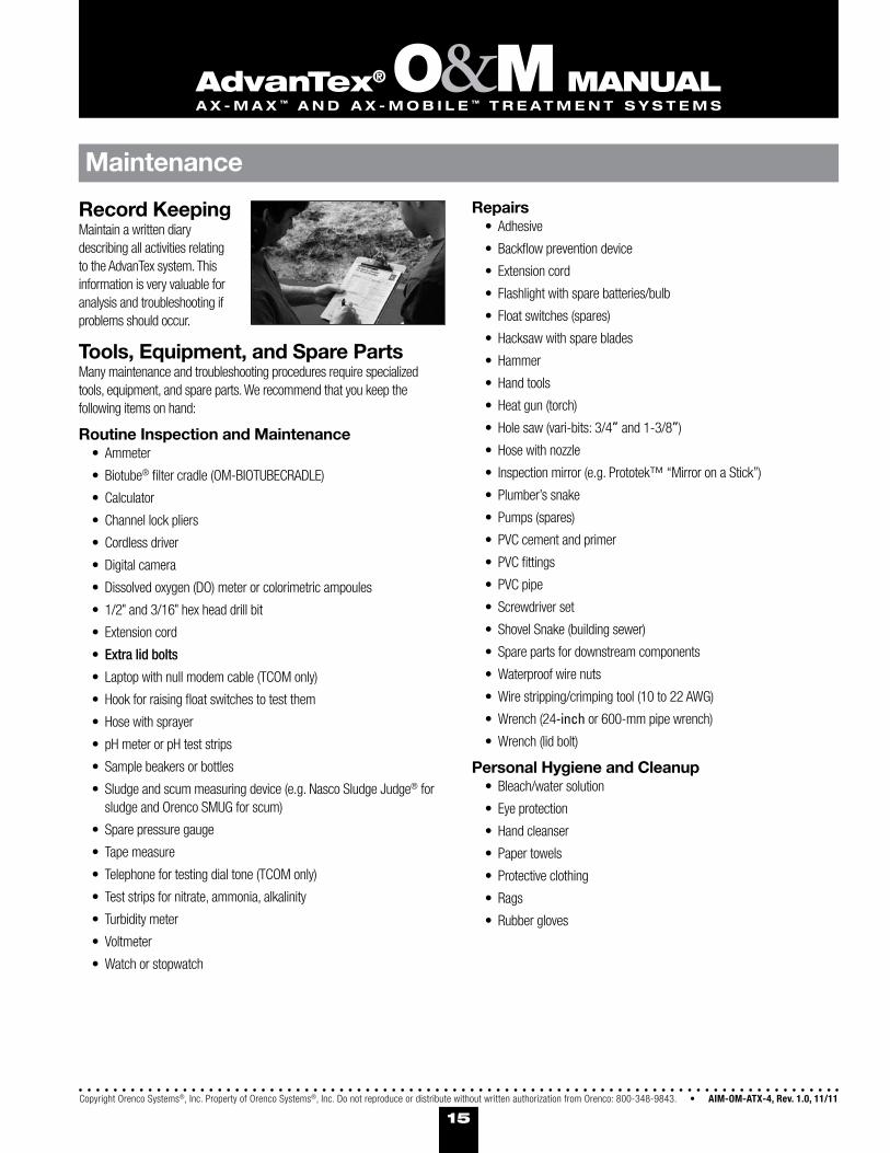
Record KeepingMaintain a written diary describing all activities relating to the AdvanTex system. This information is very valuable for analysis and troubleshooting if problems should occur.
Tools, Equipment, and Spare PartsMany maintenance and troubleshooting procedures require specialized tools, equipment, and spare parts. We recommend that you keep the following items on hand:
Routine Inspection and MaintenanceAmmeter•
Biotube• ® filter cradle (OM-BIOTUBECRADLE)
Calculator•
Channel lock pliers•
Cordless driver•
Digital camera•
Dissolved oxygen (DO) meter or colorimetric ampoules•
1/2• " and 3/16" hex head drill bit
Extension cord•
Extra lid bolts•
Laptop with null modem cable (TCOM only)•
Hook for raising float switches to test them•
Hose with sprayer•
pH meter or pH test strips•
Sample beakers or bottles•
Sludge and scum measuring device (e.g. Nasco Sludge Judge• ® for sludge and Orenco SMUG for scum)
Spare pressure gauge•
Tape measure•
Telephone for testing dial tone (TCOM only)•
Test strips for nitrate, ammonia, alkalinity•
Turbidity meter•
Voltmeter•
Watch or stopwatch•
RepairsAdhesive•
Backflow prevention device•
Extension cord•
Flashlight with spare batteries/bulb•
Float switches (spares)•
Hacksaw with spare blades•
Hammer•
Hand tools•
Heat gun (torch)•
Hole saw (vari-bits: 3/4• ” and 1-3/8”)
Hose with nozzle •
Inspection mirror (e.g. Prototek™ “Mirror on a Stick”)•
Plumber’s snake•
Pumps (spares)•
PVC cement and primer•
PVC fittings•
PVC pipe•
Screwdriver set •
Shovel Snake (building sewer) •
Spare parts for downstream components•
Waterproof wire nuts•
Wire stripping/crimping tool (10 to 22 AWG)•
Wrench (24• -inch or 600-mm pipe wrench)
Wrench (lid bolt) •
Personal Hygiene and CleanupBleach/water solution•
Eye protection•
Hand cleanser•
Paper towels•
Protective clothing•
Rags•
Rubber gloves•
Maintenance

16AIM-OM-ATX-4, Rev. 1.0, 11/11 • Copyright Orenco Systems®, Inc. Property of Orenco Systems®, Inc. Do not reproduce or distribute without written authorization from Orenco: 800-348-9843.
advanTex® O&M ManualA X - M A X ™ A n d A X - M o B I L E ™ T R E A T M E n T S Y S T E M S
Maintenance
Monthl
y
Quarte
rly
Semi-a
nnua
llyAnn
ually
Biennia
lly
Scheduled Maintenance Reference Chart Recommended Activity Period
Act
ivity
VIsually Inspect Tank Liquid Levels • 1 •Check Biotube® Effluent Filters; Clean as Required • 1 • •
Check Biotube® Pump Vault Filters; Clean as Required • 1 • •Record Elapsed Time Meters and Event Counters for All Pumps •
Inspect Spin Nozzles, Clean as Required • 2 •Confirm Proper Operation of Automatic Distributing Valve (if applicable) •
Sample Influent and Effluent Quality Parameters3 • 1 •Confirm and Record Pump Voltages and Amperages • 1 •
Inspect Distribution of Effluent in AX-Max Units; Clean as Required •Record Scum and Sludge Accumulation in Tanks •
Flush Distribution Laterals in AX-Max Units •Inspect Pumping System Components; Clean as Required •
Replace Lithium Battery in TCOM Control Panel (if applicable) •1 This maintenance schedule is only required during the first year of system operation.2 This maintenance schedule is only required during the first quarter of system operation. 3 Recommended guidelines only. Sampling should be scheduled according to regulatory requirements.
Preventive MaintenanceAs with any engineered system, such as a car or heat pump, your wastewater treatment system will work better and last longer if it is regularly maintained by a qualified service provider. The service provider should be present during installation, so he or she is familiar with the system, especially those service lines, conduits, and connections that get buried.
Your system will work better and last longer if you learn what not to put into the treatment system. There should be no disposal of toxics or chemicals into the system, such as restaurant degreasers, cleansers, wax strippers for linoleum, carpet shampoo and its waste products, and other toxics. As a general rule, nothing should go into any wastewater treatment system that hasn’t been ingested, other than toilet tissue, mild detergents, and wash water. Every system user and qualified service provider should be familiar with the basic guidelines below:
No septic additives•
No flammable or toxic products•
No excessive household cleaners•
No chlorine bleach, chlorides, and pool or spa products•
No pesticides, herbicides, or agricultural chemicals or fertilizers•
No RV waste (unless the system is specifically designed and • engineered to treat such waste)
No water softener backwash•
No surface runoff or stormwater runoff•
No excessive amounts of fats, oils and grease (FOG)•
No food byproducts•
No cigarette butts•
No paper towels, newspapers, sanitary napkins, diapers, disposable • wipes, floss, gum or candy wrappers, etc.
Preventive maintenance should start with facility user and/or homeowner education. Orenco Systems®, Inc. can provide a manual of Do’s and Don’ts to distribute upon request. To request multiple copies of this manual, contact Orenco Systems, Inc. at (800) 348-9843 or (+1) 541-459-4449.
With preventive maintenance and periodic inspections, the wastewater treatment system will function for decades.
Scheduled MaintenanceWe recommend that scheduled maintenance be performed in the time frames provided as a guideline in this section. A chart showing suggested scheduled maintenance activities and times is included below, for your convenience. However, system discharge limits and influent loads dictate actual O&M requirements. Consult Orenco, your system’s engineer, and your regulatory permit for information on your system’s specific O&M requirements.

17Copyright Orenco Systems®, Inc. Property of Orenco Systems®, Inc. Do not reproduce or distribute without written authorization from Orenco: 800-348-9843. • AIM-OM-ATX-4, Rev. 1.0, 11/11
advanTex® O&M ManualA X - M A X ™ A n d A X - M o B I L E ™ T R E A T M E n T S Y S T E M S
Monthly Maintenance1. Visually Inspect Tankage and Treatment: Once a month, during the
first year of operation, make a visual inspection of the liquid levels in the primary tank, recirc-blend chamber, and recirc-filtrate chamber. The liquid level should never be lower than the “Redundant Off” float. If liquid leaks out of the tank or treatment unit, the scum layer can drop to the level of the perimeter holes in the pump vaults and cause the screen to plug. A watertight tank is important and any leakage must be corrected.
2. Check the Biotube® Filter or Effluent Filter: Check the filters in the tanks every month during the first year of operation, and clean the filter when it is necessary. For Biotube filter cleaning instructions, see O&M Binder Appendix B.
3. Check the Pump Vault: Once a month, during the first year of operation, the Biotube Pump Vaults should be examined to determine if cleaning of the Biotube filter is necessary. If the liquid level inside a pump vault is discernibly different from the level outside the pump vault while the pump is running, cleaning is required. Remove the filter cartridge and clean it.
3. Inspect the Spray Nozzles: Once a month, during the first quarter of operation, inspect the spray nozzles in the treatment units. Observe and measure the manifold pressure. Manifold pressure values should be between 3.0-3.5 psi (20.7-24.1 kPa). If the manifold pressure exceeds 3.5 psi (24.1 kPa), it is likely that the manifold and laterals require flushing or the spray nozzles are plugged. To flush the manifold and laterals, follow the instructions from the “Start-Up and Inspection” section of this manual.
To clean out the spray nozzles, • turn the laterals so the spray nozzle turbines are pointed up and then hose off each turbine. For excessive buildup in the spray nozzles, remove the nozzles and replace them with clean nozzles. Disassemble and soak the plugged nozzles in TSP or any other appropriate cleaning agent for 30 minutes. When a spray nozzle is clear, you can see the spray nozzle turbine spin freely and the spray distribute evenly across the textile media.
After flushing and cleaning, recheck the manifold pressure. If the • manifold pressure still exceeds 3.5 psi (24.1 kPa), try either a bottle brush attached to the end of a plumber’s snake or a high-pressure washer to clean the manifold.
4. Read Hour Meters and Event Counters: Once a month, read the hour meters and event counters for the recirc-blend and recirc-filtrate chamber’s pumps. Each pump should run approximately the same number of hours and turn on approximately the same number of times as their operating counterpart. If the run times or cycle times differ significantly between pumps, determine the cause of the discrepancy and take corrective measures. For units equipped with TCOM, this information can be found on the TCOM control panel.
Quarterly MaintenanceTesting for Carbonaceous Biochemical Oxygen Demand (cBOD5); Total Suspended Solids (TSS); Fats, Oils, and Grease (FOG); Ammonia (NH3); Nitrate (NO3); and pH should be done according to regulatory requirements.
1. Take and Test Influent and Effluent Samples: If the regulatory jurisdiction doesn’t require treatment system influent and effluent testing, samples should be taken quarterly for the first year to establish a baseline. Subsequent testing after the first year may be reduced based on the establishment of this baseline. Regular samples will provide valuable information for ongoing maintenance and troubleshooting. All results obtained should be reported to the appropriate people, including Orenco.
2. Check Pump Voltages and Amperages: For the first year only, check voltages and amperages of all pumps during quarterly inspections and record them on the Field Maintenance Report Form. Refer to the start-up voltages and amperages recorded in the “Start-up & Operation” section of this document. If the voltage drop or amperage exceeds National Electric Code (NEC) requirements or the limits set by your regulatory jurisdiction, have an electrician verify the service line and check the pump windings. This procedure can be performed annually after the first year, if there is no discernible difference in voltage or amperage during the first year of checking.
Semi-Annual Maintenance1. Inspect the Spray Nozzles: Inspect the spray nozzles in the
Treatment Units as directed in the monthly maintenance section and perform maintenance as needed.
If the nozzles are substantially plugged after six months, then it’s • recommended that you begin inspecting the manifold pressure every three months (or sooner) and adjust scheduled testing and flushing of the manifold accordingly.
Maintenance

18AIM-OM-ATX-4, Rev. 1.0, 11/11 • Copyright Orenco Systems®, Inc. Property of Orenco Systems®, Inc. Do not reproduce or distribute without written authorization from Orenco: 800-348-9843.
advanTex® O&M ManualA X - M A X ™ A n d A X - M o B I L E ™ T R E A T M E n T S Y S T E M S
Maintenance
Clear Zone
Sludge Layer
Scum Layer
Wastewater Outlet to AX-Max or AX-Mobile unit
Biotube® Filter
Tank Inlet
Measuring Sludge and Scum Layers (Orenco® T-Max™ 2-Compartment Tank Shown)
Annual MaintenanceOnce a year, send copies of the complete activity diary to the appropriate person. This information is very valuable for analysis and troubleshooting if problems occur.
Measure the scum and sludge accumulation in all tanks and chambers annually. Record scum and sludge measurements on a Field Maintenance Report Form.
1. Measure the scum layer: Use a scum utility measuring gauge or similar tool to measure the thickness of the scum layer. With this measurement, determine if the distance from the bottom of the scum layer at the liquid’s lowest normal level to the bottom of the outlet tee or to the top of the inlet holes for the pump vault is 3 in. (76 mm) or less. If so, pump out the contents completely. After removing the septage contents, refill with water to the normal operating level.
2. Measure the sludge layer: Use a Sludge Judge® or similar tool to measure the thickness of the sludge layer. With this measurement, determine if the distance from the top surface of the sludge to the bottom of the outlet tee or inlet holes for the pump vault (PVU) is 6 inches (152 mm) or less. If so, completely pump out the contents. If the tank is fitted with a pump vault or effluent filter discharge assembly, take the measurement from the top surface of the sludge layer to the bottom of the vault’s inlet ports. After removing septage, refill it with water to its normal operating level.
3. Check the Pump Voltages and Amperages: Check the voltages and amperages of all pumps and record them on a Field Maintenance Report Form. Compare them to the start-up voltages and amperages
provided in the “Start-up and Inspection” section of this document. If the voltage drop or amperage exceeds NEC requirements, have an electrician verify the service line and check pump windings.
4. Inspect the Pumping System: Inspect the pumping system annually to ensure it is operating properly. Unscrew the stainless steel bolts that fasten the fiberglass lid over the pumping equipment. Remove the fiberglass lid for an inspection that includes these steps:
a. Verify there are no obvious holes or leaks in the riser or around the perimeter of the riser connection to the tank. Wetness or watermarks may be an indication of weeping.
b. Inspect the splice box to ensure it is free of water. Ensure the lid and connections are secure.
c. Verify the floats are in good condition and properly secured to the float tree. Verify the float cords are neatly wrapped inside the riser so that they cannot interfere with the operation of the floats.
d. Verify float operation. Refer to the float tests in the “Start-up & Operation” section of this document.
Biennial MaintenanceAll TCOM control panels contain a lithium battery for backup. For good measure, we recommend you replace the battery every two years. Refer to “Battery Replacement” in the Custom TCOM Control Panels and HyperTerminal Access Manual, provided in Appendix F.

19Copyright Orenco Systems®, Inc. Property of Orenco Systems®, Inc. Do not reproduce or distribute without written authorization from Orenco: 800-348-9843. • AIM-OM-ATX-4, Rev. 1.0, 11/11
advanTex® O&M ManualA X - M A X ™ A n d A X - M o B I L E ™ T R E A T M E n T S Y S T E M S
Maintenance
Corrective MaintenanceAn alarm is triggered when the liquid in a tank or treatment unit chamber reaches a level that is either higher or lower than it should be, under normal operating conditions.
When responding to an alarm, first determine the type of alarm being activated. If it is due to pump failure, test each pump manually and locate the failed pump. To replace the pump, see the “Removing & Replacing Inoperative Pumps” section of this document. Remove the access lid and visually inspect the liquid level. If a high liquid level or low liquid level has caused the alarm, follow the appropriate procedures below.
High Liquid Level Alarm1. Determine if the high water alarm is from higher than expected
usage (i.e., special event, etc.). If there is a long-term increase in flows, then timer settings need to be adjusted accordingly.
2. When a high liquid level condition exists, the source of the problem is likely to be one of the following:
a. Control panel breakers tripped – Check the circuit breakers, switches, and fuses in the system control panel. If separate breakers in the main panel were used for the pumps and controls, also check these breakers. If a breaker is found to be tripped, reset the breaker. If the breaker trips immediately, check the wiring for a short or bad breaker. If the breaker or breakers don’t trip again, then the problem has probably been found or has corrected itself. Test the automatic function of the system as shown in the “Start-up & Operation” section of this manual to verify proper operation.
b. Faulty floats – If, after checking the circuit breakers, fuses, and switches, the pump still does not operate, toggle the “AUTO-OFF-MAN” switch to “MAN.” If the pump engages, the problem is likely to be in the float system. (If the motor contactor engages but the pump doesn’t run, go to step f, “Water in splice box or loose wires.”) Pump the tank down to a level below the “Override Timer On/Off” float. Cycle the pump to simulate the timer on and off periods so the effluent is dosed to different zones of the treatment unit. Toggle the “AUTO-OFF-MAN” switch to “AUTO.” Do not leave a pump in the “MAN” position unattended. If you do, the pump can continue to operate without liquid, possibly drawing solids into the filter and causing potential failures. Isolate the float switches and check to ensure all floats are operating properly.
If a float is found to be faulty, refer to the “Removing & Replacing Inoperative Floats” section in this document.
IMPORTANT! Before doing any work on either the wiring to the level control floats and pump or inside the pump control panel, switch off the power to the system at the service entrance panel and set the circuit breakers in the panel to their “OFF” positions.
c. Pump clogged or not clean – Check the pump for discharge flow. Close the ball valve, disconnect the union in the discharge plumbing assembly and turn the union so it is facing down. Engage the pump and visually inspect the approximate flow rate being discharged. If you are unsure of the discharge rate, measure the time it takes to fill a five-gallon bucket with the discharge. Check this value against the appropriate pump curve. If the flow rate is insufficient, the pump may need to be cleaned.
d. Valves closed – If the pump operates in the proper flow range, check all downstream valves to ensure that they are in the open position. If the valves are all open, test the discharge pressure of the pump.
e. Pump failure or bad electrical connection – Check the panel to verify the motor contactor engages. If it engages but the pump doesn’t operate, then it is either a pump failure or a bad electrical connection.
f. Water in splice box or loose wires – Check splice boxes in the system for water. Remove the stainless steel screws from the splice box lid, being careful not to drop the screws. If the splice box was submerged, or if there is a crack in the conduit, there may be water in the splice box. If this is the case, remove the water with a suction bulb, sponge, or other appropriate method. Carefully check the splices to ensure they are intact and remain watertight. If all splices are found to be watertight, replace the splice box lid. In the control panel, carefully tug on each wire going to the splice box. Correct any wires that are loose. Reactivate and retest the system.
g. Leaks in tanks or treatment unit – If the system operates but can’t keep up with the flow, check the system for watertightness. A leaking tank or treatment unit can infiltrate enough water to overcome the pump. Also check for leaking fixtures in the facility or home, though it is unlikely a leaky fixture could provide enough liquid to overcome the pump.

20AIM-OM-ATX-4, Rev. 1.0, 11/11 • Copyright Orenco Systems®, Inc. Property of Orenco Systems®, Inc. Do not reproduce or distribute without written authorization from Orenco: 800-348-9843.
advanTex® O&M ManualA X - M A X ™ A n d A X - M o B I L E ™ T R E A T M E n T S Y S T E M S
Maintenance
Low Liquid Level Alarm1. Determine the actual flows in the system. If the flows are considerably
less than the timer is set for, then adjust the timer settings to match current flows. If a low level exists in the recirc/filtrate chamber, then ensure the minimum run time is appropriately set.
2. When a low liquid level condition exists, the source of the problem is likely to be one of the following:
a. Tank or recirc-filtrate chamber siphoning – Inspect the liquid level in the tank. If the liquid level is below the “Redundant Off/Low Level Alarm” float, then it’s likely that the problem is either a leaky tank or siphoning. Siphoning typically occurs when the system is pumping downhill. A system will not necessarily siphon every time it operates. It is dependent on the system design. A siphoning system can be retrofitted with an anti-siphon valve. Most siphoning problems will manifest in the first months of operation.
b. Tank or chamber leaks – If the hydraulics of the system do not allow for siphoning, it is possible that the tank or the treatment unit is leaking. Fill the tank or treatment unit to a normal operating level and return to inspect at a later time. If the liquid level is below the normal operating level, the tank or treatment unit is leaking and needs to be repaired or replaced.
Removing & Replacing Inoperative Floats
IMPORTANT! Before doing any work on either the wiring to the level control floats and pump or inside the control panel, switch off the power to the system at the service entrance panel and set the circuit breakers in the panel to their “OFF” positions.
1. Remove the float assembly. There is no need to move the settings of the floats to remove and replace a float. After noting the tether length, snap the inoperative float out of the holding collar.
2. Remove the screws from the splice box lid, being careful not to drop the screws. Remove any water found in the splice box with a suction bulb, sponge, or other appropriate method. Loosen the cord grip at the splice box and identify the appropriate wire nut for the float. Remove the wire nut and the appropriate common wire.
3. Remove the inoperative float and replace it with a new one. Push the float cable through the watertight cord grip into the electrical splice box. Leave an adequate length of electrical cord coiled inside the riser to allow for easy removal of the float assembly. Do not remove the colored markers or the paper tags from the float cords, and do not try to thread the markers and tag through the cord grip. Tighten the cord grip by hand, then test the tightness of the cord grip by tugging on the cord. A cord is secure when the cord grip is tight enough to prevent slippage.
4. Use a fresh waterproof wire nut to connect the float wires to the wires from the control panel, following the wiring schematics provided with the system plans. Always use watertight wire nuts for all connections! Attach the common wire with the other commons using a new waterproof wire nut.
5. Replace the float in the collar, using the same tether length, and reinstall the assembly.
6. Reconnect power and test the unit per the instructions provided in the “Start-up Inspection and Steps” section of this manual.
Removing & Replacing Inoperative Pumps
IMPORTANT! Before doing any work on either the wiring to the level control floats and pump or inside the control panel, switch off the power to the system at the service entrance panel and set the circuit breakers in the panel to their “OFF” positions.
1. Close the ball valve on the discharge plumbing assembly, disconnect the union, and carefully remove the pump and attached plumbing. Disconnect the pump from the discharge plumbing assembly.
2. Remove the screws from the splice box lid, being careful not to drop the screws. Remove any water found in the splice box with a suction bulb, sponge, or other appropriate method. Label the wires, Loosen the cord grip at the splice box and identify the appropriate waterproof wire nut for the pump. Label the wires and remove the wire nut.
3. Remove the inoperative pump and replace it with a new one of the same type. Push the pump cable through the watertight cord grip into the electrical splice box. Leave an adequate length of electrical cord coiled inside the riser to allow for easy removal of the pump. Tighten the cord grip by hand, not by tool; then test the tightness of the cord grip by tugging on the cord. A cable is secure when the cord grip is tight enough to prevent slippage.
4. Use a fresh waterproof wire nut to connect the pump wires to the appropriate wires from the control panel following the wiring schematics provided in the system plans.
5. Reattach the discharge plumbing assembly and carefully lower the pump into the vault or flow inducer. Be careful not to lower the pump by the cable or to pinch the cable when lowering it into the flow inducer. Reconnect the union and open the ball valve.
6. Reconnect power and test the unit per the instructions provided in the “Start-up Inspection and Steps” section of this manual.

21Copyright Orenco Systems®, Inc. Property of Orenco Systems®, Inc. Do not reproduce or distribute without written authorization from Orenco: 800-348-9843. • AIM-OM-ATX-4, Rev. 1.0, 11/11
advanTex® O&M ManualA X - M A X ™ A n d A X - M o B I L E ™ T R E A T M E n T S Y S T E M S
System Performance Because the influent characteristics, treatment train, and discharge limits for every wastewater treatment system are unique, every commercial AdvanTex Treatment System has its own unique performance signature. We strongly recommend sampling the complete system, once it is in operation, to establish your system’s baseline performance and determine your influent and effluent wastewater characteristics.
The table below provides approximate values of potential wastewater characteristic numbers at specific points in the treatment process for an AdvanTex system receiving typical strength waste as described in the AdvanTex® AX-Max Design Criteria, NDA-ATX-MAX-1.
When all parts of the AdvanTex system are operating correctly and the component values in each part of the treatment process are within the ranges above, you can expect to see typical results from field tests of AdvanTex treated effluent (filtrate) that conform to the table below.
If effluent is cloudy or smells pungent or if the biomat on the textile filter appears greasy, waxy, or oily, laboratory tests of the filtrate will aid troubleshooting.
Nitrogen Reduction ProcessTotal nitrogen reduction in standard AX-Max and AX-Mobile configurations typically exceeds 60 percent. Using alternative configurations, total nitrogen reduction can exceed 80 percent, depending on wastewater strength and other characteristics such as cBOD5, FOG; pH, alkalinity, temperature, and hydraulic retention time. Because nitrogen reduction is a complex, multi-staged process, it’s important to understand the process, its related factors, the signs of effective nitrogen reduction, and how to keep the process optimized.
It’s also important to know the total nitrogen (TN) limits required by the system user’s permit. Some regulatory agencies have no requirement; some require a specific percentage reduction of a certain kind of nitrogen (90-95 percent nitrification of ammonia nitrogen, for example); and some require TN reduction to levels at or near drinking water quality at the point of final dispersal.
Finally, because influent characteristics greatly affect the amount of nitrogen reduction possible from any given system, it’s vital to know the alkalinity of your waste source and the local or regional norms for organic and ammonia nitrogen.
In nitrogen reduction, ammonia is converted to nitrate in an aerobic environment, and then reduced through bacterial action in an anaerobic environment to nitrogen gas, which is released harmlessly to the atmosphere. Typical-strength wastewater has an ammonia level of about 60 mg/L and a TN of about 70 mg/L. Optimum nitrogen reduction typically requires the following:
Adequate alkalinity of approximately 250 mg/L or higher.•
pH of 6.5-8.5. Fixed-film microbial processes generally thrive • between pH 6.5 and 8.5. Treatment problems typically result from rapid changes in pH rather than extreme long-term mean values, although long-term levels can result in less efficient process activity.
Primary tank DO level of 0 mg/L, filtrate DO level of 2.5-6 mg/L.•
Adequate time for the nitrifying bacteria to develop (1-3 months).•
Adequate temperature (below 40° F retards the process).•
Good organic removal (cBOD• 5).
System Performance and Nitrogen Reduction Process
Wastewater Characteristic
Raw Influent
Primary Tank
Effluent
Recirc/ Blend
Effluent
Treated Effluent (Filtrate)
cBOD5 (mg/L) 250-400 150 40-60 10
TSS (mg/L) 250-400 30 30 10
TKN (mg/L) 40-80 40-80 40-80 <2
NO3 (mg/L) 0 0 2-8 20-30
FOG (mg/L) 50-150 10-20 10-20 <5
DO (mg/L) 0 0 2-6 2.5-6
Alkalinity (mg/L) 200-500 200-500 100-200 100-150
pH1 6.5-8.5 6.5-8.5 6.5-8.5 6.5-8.51 pH can be tested with litmus paper, a pocket pH meter, or a bench top pH meter.
Parameter Sampling Method
Typical Values or Properties
Effluent Clarity Visual1 Clear ( <15 NTUs)
Odor Sniff2 Non-offensive odor (Musty is OK; rotten eggs or cabbage is not OK)
Effluent Filter Visual No excessive biological growth
Biotube® Pump Vault Visual1 No liquid level differential inside/outside vault, does not clog between one-year cleaning intervals
Oily Film on Effluent Visual None; no red, blue, green, or orange sheen
Foam Visual None1 Turbidity measurements can be taken with a portable turbidity meter or calibrated turbidity standards.2 Odor can be checked with a sulfide measuring packet, an olfactory snifter device, or by sniffing the sample.

22AIM-OM-ATX-4, Rev. 1.0, 11/11 • Copyright Orenco Systems®, Inc. Property of Orenco Systems®, Inc. Do not reproduce or distribute without written authorization from Orenco: 800-348-9843.
advanTex® O&M ManualA X - M A X ™ A n d A X - M o B I L E ™ T R E A T M E n T S Y S T E M S
System Performance and Nitrogen Reduction Process
Signs of Effective Nitrogen ReductionFollowing is a brief summary of indicators of good nitrogen reduction:
Clear, odorless filtrate effluent (a “see and sniff” test is generally • considered sufficient).
Normal-looking biomat on the textile filter (light-brown to dark-brown • and gelatinous in texture).
Additional filtrate tests will show ...• Typically, low cBOD – 5, low turbidity and high clarity.
Filtrate DO of about 2.5-6 mg/L. –
Low ammonia levels (typically from <1 to 3) and relatively high –nitrate levels, since nitrification converts ammonia to nitrate. Lower nitrate levels are typically found after the denitrification process takes place.
Performance Indicators of Nitrogen ReductionTo judge the nitrogen-reducing performance (or potential) of any wastewater treatment system, be sure to check the following performance indicators:
Influent Characteristics — Influent characteristics will greatly affect the amount of nitrogen reduction that is possible from any wastewater treatment system. High solids and/or fats and cooking oils increase the oxygen demand and accumulation of material on and within the media, affecting the available oxygen for nitrification.
Clear, Odorless Effluent — Simple, “see and sniff” tests can be performed in the field. Effluent from Treatment Units that are performing well should be clear (turbidity <15 NTUs) and odorless.
Laboratory Tests for Ammonia and Nitrate Nitrogen — If the system is oxidizing ammonia to nitrate (nitrifying), lab tests should measure relatively low ammonia levels and relatively high nitrate levels in the filtrate. Because nitrification responds to many and varying conditions within the aerobic treatment processes, ammonia and nitrate nitrogen levels in the filtrate are the most ideal constituents to watch for any changes in performance. Start-up times can be plotted, optimum recirc ratios can be gauged, cleaning frequencies can be predicted, and nonvisible clogging or saturation can be detected by watching either of these constituents. Typical nitrification is expected to be in the 98-99 percent range. Investigate if the process appears to degrade by 5 percentage points or more.
cBOD5 Levels — The nitrification process requires oxygen, which is why nitrification is enhanced when cBOD5 is extremely low. Measures of filtrate cBOD5 should be <15 mg/L, although higher cBOD5 may not necessarily correlate with low levels of nitrification. When cBOD5 is high, there is a greater organic demand for oxygen, which may hamper the nitrogenous demand for oxygen. Increasing the recirc ratio should help establish oxygen balance.
Biological Growth on Filter — Biological growth on the filter media inside of treatment units is natural. The biological growth should appear light-brown to dark-brown in color and gelatinous in texture.
Dissolved Oxygen (DO) — Dissolved oxygen also provides critical information with which to diagnose how well a system is performing. Measures of filtrate DO should be in the range of 2.5 to 6 mg/L. If the DO level drops, the degree of nitrification will normally drop as well, which could be a sign of blinding or saturated flow conditions — anything that might inhibit free air from flowing into the system. (Nevertheless, it’s quite possible to have low filtrate DOs and still have high effluent quality, as measured by cBOD5 and TSS levels.)
pH and Alkalinity — pH is typically 6.5-8.5 for normal nitrogen loads. The nitrification process releases hydrogen ions into solution, which tends to lower the pH level. Alkalinity is essential for nitrification. For each part of ammonia that is nitrified, 7.14 parts of alkalinity are consumed (buffering the acidity caused by the release of hydrogen ions). Consequently, if the degree of nitrification is less than expected, it could simply be a lack of sufficient alkalinity to support more. Typically, nitrification requires alkalinity above about 250 mg/L for recirculating processes.
Some wastewater streams do not have sufficient alkalinity to support complete nitrification. In these cases, the nitrification process can deplete the alkalinity and drop the pH to a level that retards microbial activity (<6.5). Recirculating the effluent helps, since half the alkalinity can be restored in the recirc or process tank, wherever denitrification occurs (and adjusting the recirc ratios may also bring the pH back to preferred operating levels). But wastewater streams that are alkalinity-starved can’t provide for 100 percent nitrification.
Low-Flush Fixtures — The use of low-flush fixtures can reduce nitrification performance. Low-flush fixtures tend to reduce hydraulic loads, which causes elevation of wastewater constituents (i.e., higher concentrations of cBOD5, TSS, TKN, etc.). In this case, the available alkalinity in the water supply may not be adequate to accomplish the full level of nitrification desired.
Additional buffering may be necessary to accomplish the level of nitrification desired. In low alkalinity conditions, pH adjustment can be made with the addition of quicklime or hydrated lime, soda ash, or caustic. If the alkali is to be introduced at a process point preceding sedimentation zones, such as in the tank, lime would be preferred. Soda ash and caustic both contain sodium, which is a dispersant and will impede settling of solids in the tank.

23Copyright Orenco Systems®, Inc. Property of Orenco Systems®, Inc. Do not reproduce or distribute without written authorization from Orenco: 800-348-9843. • AIM-OM-ATX-4, Rev. 1.0, 11/11
advanTex® O&M ManualA X - M A X ™ A n d A X - M o B I L E ™ T R E A T M E n T S Y S T E M S
Troubleshooting Effluent Quality
Troubleshooting Effluent Quality Once you know the typical values for your wastewater treatment system’s performance, you can be proactive and troubleshoot nontypical process indicators, before system performance is affected.
Poor Effluent QualityIf your effluent samples are cloudy and color/turbidity is significantly higher than expected ( >15 NTU), do the following:
Check the effluent filters or Biotube• ® filters for clogging.
Check to see if the textile filter smells of chemicals (medication, • chlorine, etc.) or has a granular or crusty appearance. (For example, a white crystalline crust could signal that water softener discharge or industrial strength detergents have been flushed into the system.)
Check for a recirc ratio that is too high or a pump dose time that is too • long.
If effluent cBOD• 5 is high and TSS is low, a large amount of soluble cBOD5 has not yet been consumed. That could be because the recirc ratio is too low for the influent strength or insufficient start-up time has elapsed. Typical organic reduction within the first 24 hours in systems is around 75 percent or greater. As the biomat develops, greater reductions in the soluble cBOD5 will occur (typically within the first 7-10 days). With higher influent strength, soluble cBOD5 is not readily removed until the biomat on the media is established.
Check that the unit is properly ventilated.•
Interview the users about system abuse, especially regarding harmful • chemicals, solvents, strong cleaning agents, or water softener backwash.
Note: Water softener backwash is extremely high in salts, which can disrupt system performance, especially nitrogen reduction processes. Make sure that no water softener backwash is discharging into the primary tank. Plumbing water softener backwash into the primary or equalization tank voids the warranty.
If none of these troubleshooting steps makes a difference, lab tests may be necessary to determine the cause of the problem. Call your Dealer or Orenco for recommended lab tests or design remedies.
OdorIf the inside of the treatment unit smells like rotten eggs or cabbage:
Check dissolved oxygen levels using a DO meter or DO wet test kit.•
Note filtrate DO levels of <2.5 (less than 2.5) or >6 (greater than 6) • mg/L. Filtrate DO levels of <2.5 mg/L indicate insufficient oxygen. Filtrate DO levels >6 mg/L indicate excessive aeration.
If the filtrate DO is <2.5 mg/L:
Check the filter surface for evidence of clogging.•
Check that the pump is working.•
Check for proper ventilation in the unit. •
Check the recirc ratio; increase the recirc ratio if it is too low.•
Check that influent strength isn’t too high.•
Check to ensure hydraulic retention time isn’t high.•
If the filtrate DO level is >6 mg/L:
Check the influent flows and recirc ratio. If influent flows are below • normal or the recirc ratio is too high, reduce the recirc ratio.
Effluent Filter or Biotube® Filter CloggingIf a visual inspection of the effluent filter or Biotube® filter for biomass build-up shows the need for cleaning more often than once a year (an annual cleaning cycle is typical), try the following:
Verify the pump isn’t running too long (typically 3 cycles/hour). •
Check for excessive FOG and TSS in influent; if excessive, a review • of component sizes may be required.
Oily FilmAll signs of FOG anywhere in system downstream of the primary tank must be investigated prior to action. Excessive grease and oil ( >25 mg/L) is typically a design or management concern.
Sample and test at all process steps, including influent (if possible).•
Label, date, and photograph all samples.•
When photographing, use standard glass beakers and set samples • in front of a common, uniform background
Check biomat accumulation at AdvanTex Filter.•
Note if biomat is yellowish and wax-like or lard-like. If so, scrape • biomat sample for analysis.
Photograph/document biomat sample.•
Send to lab with effluent samples.•
FoamFoam rarely occurs in AdvanTex Treatment Units. If you see foam in the treatment unit, call your Dealer or Orenco.

24AIM-OM-ATX-4, Rev. 1.0, 11/11 • Copyright Orenco Systems®, Inc. Property of Orenco Systems®, Inc. Do not reproduce or distribute without written authorization from Orenco: 800-348-9843.
advanTex® O&M ManualA X - M A X ™ A n d A X - M o B I L E ™ T R E A T M E n T S Y S T E M S
Troubleshooting Nitrogen Reduction
Troubleshooting Nitrogen ReductionIf you suspect that the system is not meeting expectations for nitrogen reduction, troubleshoot each of the critical factors that contribute to optimum nitrogen reduction, to determine a cause.
Filtrate Alkalinity Too Low — Sufficient alkalinity is required to achieve the desired degree of nitrification for any wastewater treatment system, because it takes 7.14 parts alkalinity to nitrify 1 part ammonia. If filtrate alkalinity is too low:
Check the recirc ratio; a high recirc ratio increases alkalinity • consumption.
Check influent TKN or ammonia levels and source alkalinity.•
If a large quantity of nitrification is required, it may be necessary to add alkalinity-raising chemicals to the system.
Filtrate pH Too Low — Nitrification is particularly sensitive to pH but tends to thrive at levels between pH 6.5 and 8.5. The nitrification process releases hydrogen that consumes alkalinity and causes pH levels to drop. A pH level of <6 retards microbial activity of all kinds, including denitrification, and with a pH level <5.5, nitrification may show signs of degradation. Maintaining an alkalinity of 50 to 80 mg/L in the treated effluent is typically sufficient to maintain pH levels above 5.5. If the filtrate pH level is too low:
Check influent alkalinity level (pH drops when too much available • alkalinity is consumed).
Check recirc ratios; reduce if too high.•
Ask the system users about chemical discharges into the system, • including carpet cleaners, chlorine, and photo developing agents.
Filtrate DO Levels Outside Range of 2.5-6 mg/L — If filtrate DO is too low (indicating insufficient oxygen), the system may release sulfide odors during dosing events, or there may be a more lasting smell within the treatment unit(s). Try the following:
Check for surface clogging/ponding and clean as necessary.•
Check air flow through the vent assembly.•
Check the recirc ratio; if it’s too low (<2:1), increase as necessary.•
If the system’s filtrate DO is too high (indicating excessive aeration), it’s likely that excessive recirculation or insufficient hydraulic retention time are factors. Try decreasing the recirc ratio.
High Filtrate Ammonia Levels — Because ammonia is biochemically oxidized to nitrate during nitrification, high ammonia levels are a sign that something is amiss. Try the following:
Check for surface clogging/ponding and clean as necessary.•
Check for sufficient aeration (measure DO).•
Ensure no blockage of air flow into textile filter (indicated by thick • biomat development or a build-up of grease and oils).
Ensure no blockage in the manifold, causing ...•
Localized hydraulic overloading, saturation. –
“Short circuiting” between textile sheets. –
Check for sufficient alkalinity; if insufficient, consider supplemental • buffering using equipment that automatically adds an alkaline compound to the system. Call Orenco for assistance, if necessary.
Low Filtrate Nitrate Levels — AdvanTex treatment units normally yield more than 95 percent nitrification (conversion of ammonia to nitrate). Therefore, the ammonia levels in the filtrate should be low and the nitrate levels higher. Some denitrification occurs in the treatment unit, so the normal nitrate level may vary. Be sure you are familiar with the mode of operation, as some AdvanTex modes are configured to produce lower nitrate levels. If it appears that nitrification is dropping off:
Check the recirc ratio; adjust as necessary (high recirc ratios may • drive pH too low for effective nitrification/denitrification, and low recirc ratios may not provide sufficient aeration).
Verify incoming ammonia levels.•
Check recirc/blend for excessive organic food source (high cBOD• 5 may cause greater oxygen demand through the filter, reducing nitrification).
Adequate Time and Temperature — Nitrifying bacteria require one to two months to develop. Temperatures below 40° F (4° C) retard the development of nitrifying bacteria. If the AdvanTex Treatment System has been installed during a period of cold, nitrification may not “kick in” for several months until warmer temperatures are reached. Typically, a June-September installation provides the necessary temperatures for a 30-60 day nitrification start-up time. Once nitrifiers colonize, they typically continue to nitrify through normal winter conditions. Only in severely cold regions should additional insulation of the treatment unit be necessary.
Nitrogen removal (or “nitrification/denitrification”) is a biochemical process. In nitrification, ammonia is oxidized to nitrate (2NH3 converts to 2NO3 + 3H2O). This nitrate is then reduced through bacterial action (denitrification) to nitrogen gas, which is released harmlessly to the atmosphere.
During the nitrification process, about 9 parts oxygen are consumed in converting 2 parts ammonia to nitrate. Therefore, depending on the concentration of ammonia, a considerable amount of air may be needed. Other processes, like cBOD5 reduction, may

25Copyright Orenco Systems®, Inc. Property of Orenco Systems®, Inc. Do not reproduce or distribute without written authorization from Orenco: 800-348-9843. • AIM-OM-ATX-4, Rev. 1.0, 11/11
advanTex® O&M ManualA X - M A X ™ A n d A X - M o B I L E ™ T R E A T M E n T S Y S T E M S
Troubleshooting Nitrogen Reduction
occur simultaneously and further elevate the demand for aeration, especially if the organic level is high. In an abundance of air, all the aerobic or facultative microbes compete for their share of oxygen.
When the organic concentration is high, the microbes that oxidize organic matter, primarily the heterotrophic bacteria, are aggressive and tend to outcompete other microbes for the available free oxygen in solution. Ammonia is oxidized by autotrophic bacteria, which do not have as aggressive a growth rate, so if oxygen is not abundant, nitrification suffers. Consequently, the nitrification process usually lags until the organic concentration is depleted or until sufficient oxygen is present. At a 2.5:1 cBOD5/TKN ratio, the nitrifiers may only make up about 10 percent of the microbial population. At 0.5:1 cBOD5/TKN, the nitrifiers make up about 35 percent of the population.
In a filtering process, the filter column must be deep enough or the filter media must be efficient enough at filtering organic particles to deplete concentrations of organic material to a level in which a sufficient population of nitrifiers will be sustained. The physical (dimensional) features of the filter will vary depending on the media’s characteristics — void ratio, moisture holding capacity, and effective surface area per unit volume ratio.

26AIM-OM-ATX-4, Rev. 1.0, 11/11 • Copyright Orenco Systems®, Inc. Property of Orenco Systems®, Inc. Do not reproduce or distribute without written authorization from Orenco: 800-348-9843.
advanTex® O&M ManualA X - M A X ™ A n d A X - M o B I L E ™ T R E A T M E n T S Y S T E M S
Notes___________________________________________________
___________________________________________________
___________________________________________________
___________________________________________________
___________________________________________________
___________________________________________________
___________________________________________________
___________________________________________________
___________________________________________________
___________________________________________________
___________________________________________________
___________________________________________________
___________________________________________________
___________________________________________________
___________________________________________________
___________________________________________________
___________________________________________________
___________________________________________________
___________________________________________________
___________________________________________________
___________________________________________________
___________________________________________________
___________________________________________________
___________________________________________________
___________________________________________________
___________________________________________________
___________________________________________________
___________________________________________________
___________________________________________________
___________________________________________________
___________________________________________________
___________________________________________________
___________________________________________________
___________________________________________________
___________________________________________________
___________________________________________________
___________________________________________________
___________________________________________________
___________________________________________________
___________________________________________________
___________________________________________________
___________________________________________________
___________________________________________________
___________________________________________________
___________________________________________________
___________________________________________________
___________________________________________________
___________________________________________________
___________________________________________________
___________________________________________________
___________________________________________________
___________________________________________________
___________________________________________________
___________________________________________________
___________________________________________________
___________________________________________________
___________________________________________________
___________________________________________________
___________________________________________________
___________________________________________________
27Copyright Orenco Systems®, Inc. Property of Orenco Systems®, Inc. Do not reproduce or distribute without written authorization from Orenco: 800-348-9843. • AIM-OM-ATX-4, Rev. 1.0, 11/11
advanTex® O&M ManualA X - M A X ™ A n d A X - M o B I L E ™ T R E A T M E n T S Y S T E M S
Notes___________________________________________________
___________________________________________________
___________________________________________________
___________________________________________________
___________________________________________________
___________________________________________________
___________________________________________________
___________________________________________________
___________________________________________________
___________________________________________________
___________________________________________________
___________________________________________________
___________________________________________________
___________________________________________________
___________________________________________________
___________________________________________________
___________________________________________________
___________________________________________________
___________________________________________________
___________________________________________________
___________________________________________________
___________________________________________________
___________________________________________________
___________________________________________________
___________________________________________________
___________________________________________________
___________________________________________________
___________________________________________________
___________________________________________________
___________________________________________________
___________________________________________________
___________________________________________________
___________________________________________________
___________________________________________________
___________________________________________________
___________________________________________________
___________________________________________________
___________________________________________________
___________________________________________________
___________________________________________________
___________________________________________________
___________________________________________________
___________________________________________________
___________________________________________________
___________________________________________________
___________________________________________________
___________________________________________________
___________________________________________________
___________________________________________________
___________________________________________________
___________________________________________________
___________________________________________________
___________________________________________________
___________________________________________________
___________________________________________________
___________________________________________________
___________________________________________________
___________________________________________________
___________________________________________________
___________________________________________________

28AIM-OM-ATX-4, Rev. 1.0, 11/11 • Copyright Orenco Systems®, Inc. Property of Orenco Systems®, Inc. Do not reproduce or distribute without written authorization from Orenco: 800-348-9843.
advanTex® O&M ManualA X - M A X ™ A n d A X - M o B I L E ™ T R E A T M E n T S Y S T E M S
®
800-348-9843+1 (541) 459-4449www.orenco.comwww.vericomm.net
Orenco SystemsIncorporated
Changing the Way theWorld Does Wastewater®
COMMERCIAL
O&MManual
AdvanTex® Treatment System AXN Models meet the requirements of NSF-ANSI Standard 40 for Class I Systems.
NSF/ANSI STANDARD 4
0
NSF®