Embed Size (px)
Citation preview


TANGENT Q'206 North Dreamy Draw Drive
hoenix, Arizona 85020
"AX" Series For professional sound reinforcement and recording / Model 2402ax, 1602ax, 1202ax and 802ax. Tangent's stereo mixing consoles are designed to provide the highest quality sound available in the world today. And that's no idle claim.
Modern Recording, reviewing the predecessor to this series. discovered "astonishingly quiet" performance and "superlative square wave response."
Modem Recording's engineers also found distortion measurements so low they were "typically masked by the residual noise leveL"
These verified noise and distortion measurements totally obliterate the unverified performance claimed by other mixer manufacturers. But the best is yet to come.
This "ax" series of Tangent consoles has even lower distortion and better noise performance than the model reviewed by Modern Recording!
What this means to the sound engineer is total transparency and clarity of sound. And features like Solo. submaster grouping and three independent Monitor/Reverb/ Effects busses give complete professional control.
Finally. and surprisingly. the price is moderate. Live-performance features. reasonable cost. and absolute quality combine to make Tangent the professional choice in mixing consoles.
INPUT MODULE PEAK input LED flashes as the signal peaks pass + 15dB. Internal headroom is an excellent +20dB.
GAIN control works in conjunction with the Peak LED to prevent input overload.
HI range equalization is the shelving type with 15dB of either boost or cut. The shelf begins at 10.000Hz
Tangent Systems, Inc•• • &
MID range equalization is of the peak and dip variety. giving 1 OdB of boost or cut at 1 ,500Hz.
LO range equalization gives 15dB of boost or cut to the lower frequencies in a shelving manner. The shelving effect begins at 100Hz. As noted in Modem Recording. "The equalizer is very similar to that found in top-grade stereo preamplifiers or receivers."
EFFECTS Send conrol determines how much signal from that channel goes onto the Effects Buss and then out to an external flanger, tape-echo unit, or other effects device. The Effects Buss, acting as an independent mixer-within-a-mixer, may be used as a second Monitor mix if desired.
SPECIFICATIONS
NOISE
An measurements were made wi1l1 an HP 400 aeries average reading meler and conec1ed by t .OSdb lor RMS noise. All readings are unweighled and band I,mrted at6dB/oc1ave 8120Hz and 48dB/ocIave al 2OI<Hz. OdBv = . n4 vo~s. Since !he console OOIPU~
REVERB Send knob controls how much signal from that channel goes onto the ,Reverb Buss. The Reverb Buss then drives either an external reverberation unit or the optional internal reverb. The optional internal' reverb features a three-spring Accutronics Type 9 Chamber, and utilizes a compressor in the drive circuitry to minimize the "boing" sound usually associated with spring reverb.
MONITOR Send controls are used to determine what the musicians hear on stage.
SOLO cuts off the normal signal feed to the headphones and feeds only the input module whose Solo switch is engaged.
are low impedance. load impedance does not aIIecIlhe noise.
Mic Pre-amp equivalenl input noise (Zs ~ ISO ohms)
OISTOATION
Total HarmonIC or Inlermodulation (THO or 1M. channel outputs at -16dBm or .24d8v inlO 10Kohm. 20Hz-20kHz)
SLEW RATE
Measured al any poinl in !he aUdio chain
FREOUENCY RESPONSE
Arty input 10 any oulput · . (3dB bandwidth extends from below 10Hz 10 above SOkHz) .
Maximum output 20Hz·2OI<Hz
MAXIMUM GAIN
Balanced Lo-Z microphone Hi-Z line or microphone Buss-in Gain Conlrol Range
Peak Indicator Threshhold
Ctosslalk
Input Channel Equalization Treble Midrange Base
MeIer Calibration
.- • -----
·127.OdBv mtnimum -128.SdBv typical . 130.6dBv 1heorelicallimit
Less than 0.075% minimum Less than 0.004% typical at 1kHz
10 lIOfts/micro-second minimum 13 voIts/micro-second typical
~O.SdB 20Hz· 20kHz
• 24dBv ( lOKOIvn load) - ledBm (600 Ohm load)
82dB 64dB 20dB 40dB
.'5dB 6OdB@lkHz
=ISdB@ 10kHz shelving :'OdB@ t:5kHz peak/dip .;: I SdB @ 100Hz shelving
0dB ••4dBv (IOkOhm)
•

QUO T E
Library of Congress
Modifications to 1202 AX
1. Balance (electronically) the direct outputs on each input
(Use tip-ring-sleeve \;" jack)
2. Mic-Line input select switch on each input module. Line input
shall be variable by input gain control. Line unput shall be
capable of accepting a +4 db input.
3. Direct output from each module shall be balanced on tip-ring-sleeve
!a" jack. Output signal shall be capable of exceeding +24 dbm.
(600 0 hm)
4. All master section balanced outputs, (left master, right master,
monitor, and mono) shall be capable of exceeding +24 dbm (600 ohm).
,.
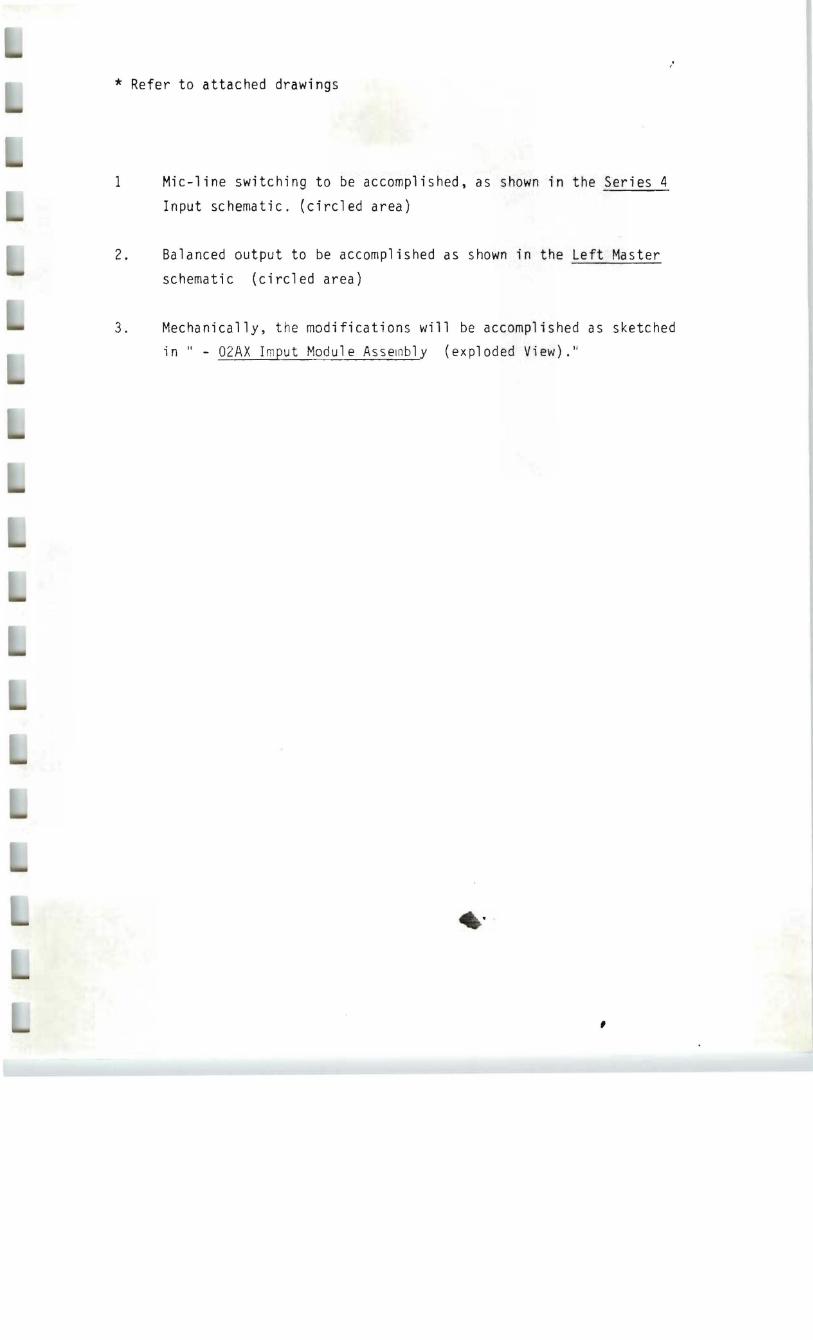
* Refer to attached drawings
1 Mic-line switching to be accomplished, as shown in the Series 4
Input schematic. (circled area)
2. Balanced output to be accomplished as shown in the Left Master
schematic (circled area)
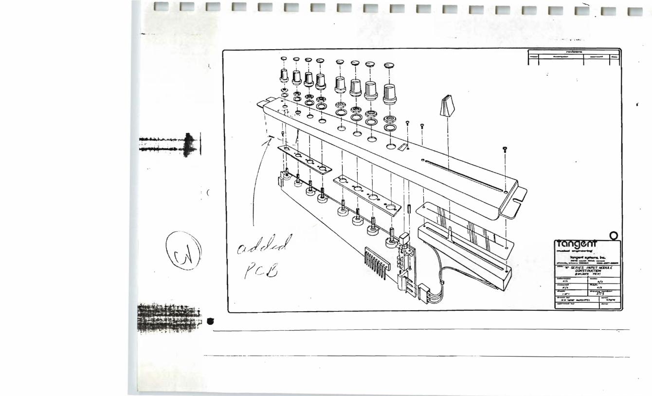
3. Mechanically, the modifications will be accomplished as sketched
in " - 02AX Imput Module Asselnbly (exploded View)."
,
..
~_
_-f-
~ \~
' \
'-.'
f· I
/
I . i~
,'\ (
j
• // ~
.\ / ~I
~.

I /' ..
(
• * t -I: L
~---+
0-Q--«
) -() o--~-W -{)
-o-
--Q-~{)
-&2_
. o---Q

Page 11
SIDETONE The Sidetone adjustment will vary the level of your mic through your headset thus reducing the chance of a" very painful feedback loop occuring between your mic and headsets. Th~s adjustment is accomplished by turning up your mic level to normal operating level. Then while speaking into the mic rotate the Sidetone adjustment t with a small flathead screwdriver t
until a null is found where your voice is at minimum through your headsets. This is the point·of maximum Sidetone rejection. Please note that the Sidetone does not effect the level of signal going to or from other stations.
--
" ".·:0:·
D 111-
•
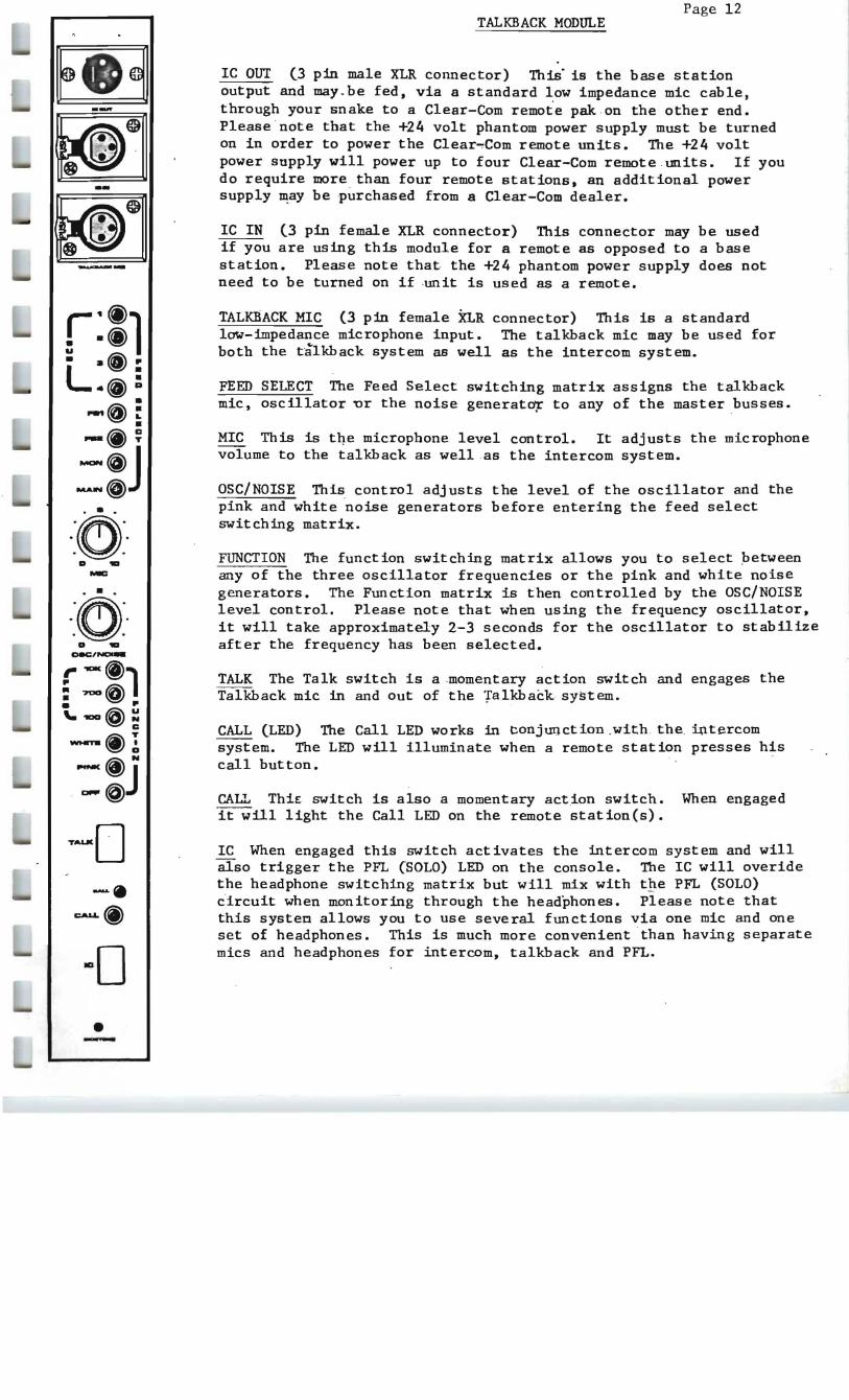
Page 12 TALKBACK MODULE
IC OUT (3 pin male XLR connector) This" is the base station output and may . be fed, via a standard low impedance mic cable, through your snake to a Clear-Com remote pak on the other end. Please note that the +24 volt phantom power supply must be turned on in order to power the Clear~Com remote units. The +24 volt power supply will power up to four Clear-Com remote units. If you do require more than four remote stations, an additional power supply may be purchased from a Clear-Com dealer.
IC IN (3 pin female XLR connector) This connector may be used if you are using this module for a remote as opposed to a base station. Please note that the +24 phantom power supply does not need to be turned on if ·unit is used as a remote.
TALKBACK MIC (3 pin female XLR connector) This is a standard low-impedance microphone input. The talkhack mic may be used for both the talkhack system as well as the intercom system.
FEED SELECT The Feed Select switching matrix assigns the talkhack mic, oscillator ur the noise generat~ to any of the master busses.
MIC This is tqe microphone level control. It adjusts the microphone volume to the talkhack as well as the intercom system.
OSC/NOISE This control adj usts the level of the oscillator and the pink and white noise generators before entering the feed select switching matrix.
FUNCTION The function switching matrix allows you to select petween any of the three oscillator frequencies or the pink and white noise generators. The Function matrix is then controlled by the OSC/NOISE level control. Please note that when using the frequency oscillator, it will take approximately 2-3 seconds for the oscillator to stabilize after the frequency has been selected.
TALK The Talk switch is a .momentary action switch and engages the Talkhack mic in and out of the Talkhack system.
CALL (LED) The Call LED works in conjunction.with the intercom system. The LED will illuminate when a remote station presses his call but ton.
CALL ThiE switch is also a momentary act.ion switch. When engaged it will light the Call LED on the remote station(s).
IC When engaged this switch activates the intercom system and will also trigger the PFL (SOLO) LED on the console. The IC will overide the headphone switching matrix but will mix with t~e PFL (SOLO) circuit when monitoring through the headphones. Please note that this systen allows you to use several functions via one mic and one set of headphones. This is much more convenient than having separate mics and headphones for intercom, talkhack and PFL •
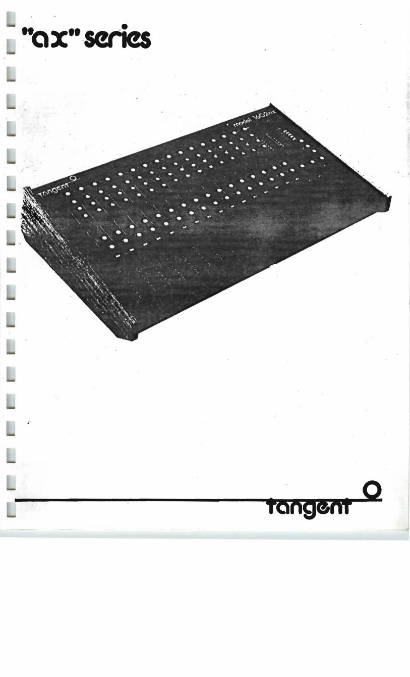
""x"se ..'-I . nes
. Q TbngClM
WARninG!!! THERE ARE APPROXIMATELY 18,496
. WAYS TO CONNECT THIS CONSOLE
BUT, ONLY ABOUT 136 Wll.L WORK.
TO . AVOID FRUSTRATION, CONFUSION
AND MURPHY'S LAW. PLEASE READ
THIS OWNER'S MANUAL BEFORE
OPERATIOll.
.'
INTRODUCING THE TANGENT "AX" SERIES OF QUALITY AUDIO MIXERS
Here at Tangent, we realize the need for a reliable,
flexible mixing board at a reasonable price, Our answer to
that need is the "ax" Series of quality mixers. All four "ax"
models, the 802ax, 1202ax, 1602ax and 2402ax, are identical in
.features and functions, other than channel configuration. Ex
terna1 power supply, channel solo capability, and built-in
phantom power, features commonly seen on the most expensive
mixers are standard equipment for the "ax".
In the studio or on the road, your Tangent mixer is right
at home. And with a little tender loving care, it will give
you many years of reliable service.
If for some reason you should have a problem with your
console, consult your local dealer, or contact us directly at:
Tangent Systems, Inc. 2810 S. 24th St., .Suite 103 Phoenix, Arizona 85034 (602) 2~7-0~53 .
Page 2
All four models, 802ax, 1202ax, 1602ax and 2402ax, are
identical in function, so the guidelines in this booklet will
apply to yourconso1e,.regard1ess of the number of channels.
A few terms will, reappear in the course of explaining
the functions and capabilities of Tangent mixing consoles. A
''buss'' can be defined variously as an electrical junction; the ,
sum of any number of electrical outputs appearing at one point,
or the common junction of any number of outputs. The "ax"
. Series boards have" five busses: Left Master, Right Master,
Effects, Reverb and Monitor.
In regard to the formidable "array of phone jacks on the
back panel: a jack can be made to function as a switch, acting
as an interupter to a circuit when a plug is inserted. Such a
receptica1 is said to be "norma11ed", as it offers a choice "be
tween diverting a signal or letting it follow its" normal path.
Classification of signal types is also important. Mixing
boards channel signals from one outside source to another, such
as a signal from a mic~ophone channeled to a preamplifier, in
through an input, and out througb an output, never to be seen
again by the mixer. A "send" is a buss output signal or feed
meant to be returned to the console after external processing.
A send is used in conjunction with a "return", a signal that "
comes back to the board from an external processing unit, such
as a compressor Or phase shifter.
:. ~' l
'" . "i
. . , "

--
P...age 3
The top panels of the "ax" series mixers contain a row of metal panels called "modules". Three kinds of modules form the basis of the "ax" series boards: input modules (8, 12, 16, or 24), output modu~es (2) and a monitor module. The right and left output modules have different features, although each generally serves as a master for mixing and balancing the stereo output signals.
INPUT MODULE
In a live or studio mixing situation the input module controls signals coming into the console. The red PEAK LED flashes a warning as the signal pe$l'ks reach or exceed +15dB, with an internal headroom of another 5dB. PEAK LED monitors the signal after it has been equalized (post-EQ).
The gray GAIN -control is the knob used to adjust input, by varying the gain of the micropnone pre-amp. Set tne GAIN oy turning it up until the PEAK LED lights, then oack off slignt1y until it goes out. The range is 40dB, from 16 to 56 dB.
The three-band equalization is controlled oy the tnree red knobs labeled "EQ". Both the HI and LO range controls are shelving type with 15dB of either cut or boost. The HI range sne1f begins at 10,OOOHz, the LO range at 100Hz. The HID range control is a peak and dip type, giving a ooost or cut of 10dB at 1400Hz. The midrange control is particularly effective at origntening or muting a singer's voice. All three EQ controls nave a center detent, indicating when the equalizer is not affecting the signal.
The next three knobs are joirit1y labeled "SENDS". The first control, EFFECTS SEND, determines nowmuc1l signal from that cnanne1 goes into the Effects Buss and tnen out to an external effects device (such as a f1anger or echo-delay unit). The olue EFFECTS SEND knob controls tne signal after it has passed througn the equalizer, but before it goes to tne input module's volume control. This prefader feature can be modified internally at any Authorized Tangent Service Cen ter.
The blue REVERB SEND knob-controls how mueh signal from that channe1d goes into the Reverb Buss ;~ The Reverb Buss then drives either an external reverberation unit or the optional internal reverb. REVERB SEND is post-EQ and post-fader; the configuration ~BD easily be changed to pre-fader at any Autnorized Tangent Service Center.
The third of the sends is the yellow MONITOR SEND control, used to let the stage performers hear themselves. The ~ONITOR SEND SEND is independent of the channe1~s equalizer and volume controls, and gives the musician a completely accurate version of his performance. :
~"'K •
.-~. --· YJ.D ..,
EOFFECT8
:r:C)"~-!- ~ ~ }.
REV!!"il'~'-~' ':CJ'~'\.· · I
_ - ·.". "__ --"II'~. ..
.J'ONIT&
BOLOIQ e
0
B
'00
30
I,40= 80
., '7D

INPUT MODULE CONT.
The gray PAR control positions the signal from the input module within the stereo field. The signal from. say a backing vocalist can be shifted more to the right or left to enhance or compensate for the overall mix.
The gray SOLO button serves as an override on the headphone line. allowing the engineer to listen to each module individually through the headphones. while the audience and performers continue to hear their respective mixes. Engaging any SOLO button ac~iyated the DC-controlled FET switching. and any number of channels may l>e activated at the same time. The SOLO signals are monaural and post-EQ.
The VOLUME control determines the gain of the si~al sent to the left and Right Master Busses. The straight-line fader bar has a lOO-millimeter travel.
i '
NOISE: All nwnuranonb ___ mad. with In HP 400 sena ..... Nading mel., Ind cometed by I ~ ..... RMS noia. All ra6..,. '" un_Vh1ed....s twond limited .t 6 cIl!{oct... .t 20 Hz .m 48dBl~ .t 20kHL OdBor • :n_ ....1>. Sinc.o the tonS<ft DUtpub ~ 1_ irrc>edlnca. 10M! ~.ncam. nat .nod the noia. .,Mie,.,..,,,,, equivalent inPut ...... (ZJ·150~ ·127.adBw ....... muna
·128.sc1Bv typiaI ·130..8dBw theomiallimlt
. .
ClSTORTION Tobi Hormonic ." Intonnod.utlcn
(l1iO.. 1M. ~neI DUtpub .t +IBdBmw - L.... thon o.075'!ro ....ni ......... . • 24dBw Into IIl1<ohn\. 21Hl·201<H13 Lao than ~typial.t lkHl
.'
" .
5L£WRA1£ -.' Masunid 8l Iny point in tho oudio elwin -10 wCllt!lmicrc>1OOCUMI mIni_
- ' 13 Ycit!,lmicTC>1OOCUMI typicII
f"R£QUENCY RESPONSE
Any input to Iny output.(JdB _width ul~ from ...._ 11HZ to.- 50kHr) s.a5dB. 20Hz..2O<Hr
Mollilftlm output 2IHZ·2O<Hr + 24dBor (I OkOhm lo.dI .IBdBm (600 """' I....,
MAXlU ...... GAlN -&brad Lo-Z miu~ 82d8 tt;.Zli....~ 64cJB e.-e - 20dB Win Ccnn:oI RI.... ~
Pal< 1nd"atD< '"'__ +1_
e.-.. GOdB., kHr
1-"0wvwI EcjuoIiutioll ~15cIB. 10kHz ~T_ :=,...,. ~10dB.,.5kHz .- ~15cfB.IOCHz_....
Mol..c.r-.-- OdS· +4dBw 1101<01..",

Page 5
MONITOR MODULE
The red SOLO LED INDICATOR lights up when one or more of the solo switched are engaged on the input modules. This serves as a reminder to let you know why you're hearing only one or two channels • .
The gray HEADPHONE SELECT switched let you meter and listen to the Effects, Reverb :·or Monitor Busses, or to mono or'stereo versions of the signal from the · ~ins.
A stereo headph9ne jack is located on the rear panel. Also on the rear panel you will find a pair of phone jacks laoeled CR RIGHT and CR LEFT. These are Control Room feeds, and are paralelled with the left and right outputs of the headphone amp. These feeds are provided to enaole you to use a stereo,amp1ifier and speakers for monitoring purposes rather than using"headphones.
The next four knobs are level controls. The first two PHONES and SOLO, affect the volume heard through the headphones. The gray PHONES control determines the volume of the signal or signals coming from any source other than the input modules. The gray
_ SOLO control handles the volume of signals coming from any input modules which have the SOLO outtonsengaged.
The gray MONO level knob is the master control for the Mono output. This signal is the sum of the left and right output master volumes.
The yellow MONITOR level knob controls the final level of the Monitor output signal. The red LO-CUT button switches a 100HZ, l2dB/octave Butterworth filter into the signal path to eliminate bass rumble caused by air conditioning or other mechan_ ical noises.
• "
--.0 c::l• . " , ~~ I MON~
~[dlMAWc::J
e
,w .··0 .-;~-
D 'ID PHO....
• • ' ... 0
~O-DIOOl.D'ID
- ' ...-:0;- . ~ .
. ..'.-:0.Jb".1T~ ,
L~~
• MONITOR

--
Page 6
LEFT OUTPUT MODULE
The red PHANTOM POWER LED lights up when the phantom power supply ~S turned on. There is an on/off switch on the rear panel for the +24 volt phantom FOWer supply.
A CALIBRATION CONTROL is positioned just above the LED METER. The meters are calibrated at the factory for use with unbalanced line outputsjfor any necessary adjustments, refer the unit to qualified service personnel. Adjustment - is recommended for use with balanced line outputs. The LED METER give a color-coded reading of the left master output.-,
The blue EFFECTS knob cluster controls the amount and routing of a signal passing through the Effects Buss. EFFECTS SEND determines how much of the signal from the Effe'ets Bus's is 'sent to ' a piece of external equipment for processing. EFFECTS RETURN determines how much of the returning, processed signal is added to the Left and Right Busses. EFFECTS PAN allows the engineer to position the returning signal within the stereo field, from extreme right to extreme left. , .
The gray AUX L acts as a level control for one channel of a signal coming into the board from an auxiliary outside source, such as a pre-taped effect. You can run a taped piece of music during breaks through the AUX input without using an input module and disrupting channel assignments.
The red LO-CUT switch activated a Butterworth filter identical to the ,one found on the monitor ,module.
The LEFT SUBMASTER is actually a master for, the left output; it also operates as a submaster control when the ,mono output is used.
=
.....0.
[.-.'-0-. ,,:._-. ~-.
l~7_.
-~-. -20-0
e -; .
r(~:'D 10
Be'NO _. JI _
r~-·." .
L" ~ :0:·
,L A-e
, .~. ( , - )
.~~ '~~.' '-. - . 'iux~ '
LOCUTt:] , I.
-(9 0:
LEFT &UBMA~
ED
a-
li
~-
RD
30
.o
lIO-
M)':"
70
S

--
Page 7
RIGHT OUTPUT MODULE
A green POl.JEP. LED functions as an onloff indicator. showing that the power. supply ~s generating DC voltage for tbe board.
The CALIBRATION CONTROL and LED ~TER are identical in function to those found on the left output ~0~u1e. ~th the meter sh~ng the output of the Right lfuster.
The blue REVERB knob cluster controls the amount and routing of a signal passing through the Reverb Buss. REVERB SEND determines how much of the signal from the Reverb Buss ~s sent to a ~tiece of externa;l 'equipment(or to the ' optional :internal reverb un~t) for 'Processing. REVERB RETURN determ:ines how much of the returning, processed signal ~s added to the Left and Right Busses. REVERB PAN allows the engineer ·to posit~on tbe returnipg s~gna1 within the stereo field, from extreme right to extreme'left.
the gray AUX R acts as a level control for the other channel of an outside signal source, as explained in the left output module section.
The red LO-CUT switch is also identical in function to the one on the left output module.
The RIGHT SUBMASTER also function as a master for tbe right output, and operates as a suomaster control wben the mono output is used.
.....0. o-e'r°:ll--e-O.. .
.t/~ '--. l
_7_ 0 -tD-O -20-0
. . :oe
:·D "OD
BEND 4 ••r[0:·
l5:· '"· _N..
::0:· · 0 "OD
AUX"
LO-CUT~
0
.~ .
..,
110= :10
40
Page 8
BACK PANEL FUNCTIONS
The "ax" series back panels contain a bank of connectors for quick, complete acces~ to the boards' input/output functions. The back panel configuration for each model in the series is similar, with the only difference between the 802ax and 2402ax being the number of input module connectors. Two kinds of connectors are used: phone jacks, for unbalanced lines, and XLR-type, for balanced lines.
Each input module terminates in three phone jacks and one XLR-type receptacle. The rows of module connectors are 1aoe1ed "INPUT" and have a white wraparound dividing line broken by the number of the channel. The two top jacks, the SEND-RETURN ACCESS, give direct access to the patb of the signal after ··it has entered the module. This feature allows the signal from each source to De routed through a separate processing or" supplementing device ou~side the mixer, if desired, through the SEND, and returned through the RETURN jack. It also provides access to the signal for multitrack recording purposes. SEND-RETURN ACCESS is post-EQ; when the jacks are left open, or with SEND alone patched, the signal flow is uninterrupted. Only the RETURN jack is norma1ed.
The LINE/Hi-z phone jack is the unbalanced line input~ used for highimpedance inputs. High-impedance signals, such as IDOSt electric guitars or. many public address microphones, are suoject to interference, and their connecting cables should not exceed ten feet in length.•
On the other hand ,the LO-Z MIC input, or oa1anced IDicrophone input, is designed with both conductors .from the microphone running symmetrical to ground, and cable lengths of several miles will result in very little signal loss or RF interference.
To the left of the 8, 12, 16 or 24 columns of input module connectors are the MAIN OUTPUTS, four phone jack receptacles (Hi-Z) and four XLR-type connectors (Lo-Z). The LEFT and RIGHT MAIN OUTPUTS are the sources of the signals mixed in the Left and Right Master Busses; they permanently send the mixed signal to a stereo power amplifier (or two mono amps, one per side). The MONO MAIN OUTPUT is simply the sum of the right and left output signals, both funneled in~ to one terminal, again, through either a phone jack or an XLR-type connector. The MONITOR MAIN OUTPUT is the source of the signal mixed through the Monitor Module, to be permanently sent to the stage monitors. The terminals of three of the five busses are clustered in this section.
The other - two busses terminate in phone jacks above the ''MAIN OUTPUTS" lettering. The REVERB SEND and REVERB RETURN jacks provide access to the path of the signal sent to an external reverb unit, or other processing device. If your board has an internal reverb unit, using these jacks will bypass it. The REVERB SEND, REVERB RETURN and REVERB PAN functions are controlled by the blue knobs of the right output module. To the right of the REVEP~ SEND are the EFFECTS SEND and EFFECTS RETURN jacks, also used to provide access to the path of a signal sent to an external processing device. The EFFECTS SEND, EFFECTS RETURN and EFFECTS PAN function are controlled by the blue knobs on the left output module. The EFFECTS RETURN jack and the REVERB RETURN jack are norma11ed.

BACK PANEL FUNCTIONS CONT.
Another pair of phone jacks grouped with the Main Outputs are the AUX INPUTS, LEFT and RIGHT. These jacks allow access to the Left and Right Master Busses, respectively and are controlled bytbe gray knobs labeled AUX L and ADX R on the left ar.d r~ght output modules.
In the lower left hand you will see a four pin male XLR-type connector. This is where the PS500 power supply plugs in. Right next to the power supply jack is a switch. This switcb turns the phantom power supply on and off. There is no main power switcb. Our engineers feel that a main switch is unnecessary, and just adds one more mechanical part that could fail.
To the extreme right of the back panel is a round nine pin receptical that looks like a tube socket. This is the buss access jacK and is used for combining two boards. By taking the outputs of one Doard and running them into tbebussaccess of a second board,you can use the first board as a submaster mix and it's signals will De feed directly onto the busses going to the master section of the second board.
Access jack pinouts are as follows:
Pin 1 - Left Master Buss
Pin 2 - Right Master Buss
Pin 3 - Effects Buss
Pin 4 - Reverb Buss
Pin 5 - Monitor Buss
Pin 6 - Ground
Pin 7 Solo DC
Pin 8 - Ground
Pin 9 - Solo Audio