Embed Size (px)
Citation preview

User’s Manual 2006-06-14
A Dynamixel X-12 Closer to Real,

DYNAMIXEL AX-12
Contents
1. Summary 1-1. Overview and Characteristics of AX-12 Page 2
1-2. Main Specifications Page 3
2. Dynamixel Operation 2-1. Mechanical Assembly Page 4
2-2. Connector Assembly Page 5
2-3. Dynamixel Wiring Page 6
3. Communication Protocol 3-1. Communication Overview Page 9
3-2. Instruction Packet Page 10
3-3. Status Packet Page 10
3-4. Control Table Page 12
4. Instruction Set and Examples 4-1. WRITE_DATA Page 19
4-2. READ_DATA Page 20
4-3. REG WRITE and ACTION Page 20
4-4. PING Page 21
4-5. RESET Page 22
4-6. SYNCWRITE Page 23
5. Example Page 24
Appendix Page 30
1
DYNAMIXEL AX-12
1. Dynamixel AX-12
1-1. Overview and Characteristics of AX-12
Dynamixel AX-12 The Dynamixel series robot actuator is a smart, modular actuator that incorporates a
gear reducer, a precision DC motor and a control circuitry with networking functionality,
all in a single package. Despite its compact size, it can produce high torque and is
made with high quality materials to provide the necessary strength and structural
resilience to withstand large external forces. It also has the ability to detect and act
upon internal conditions such as changes in internal temperature or supply voltage.
The Dynamixel series robot actuator has many advantages over similar products.
Precision Control Position and speed can be controlled with a resolution of 1024 steps.
Compliance Driving The degree of compliance can be adjusted and specified in controlling position.
Feedback Feedback for angular position, angular velocity, and load torque are available.
Alarm System The Dynamixel series robot actuator can alert the user when parameters deviate from
user defined ranges (e.g. internal temperature, torque, voltage, etc) and can also handle
the problem automatically (e.g. torque off)
Communication Wiring is easy with daisy chain connection, and it support communication speeds up to
1M BPS.
Distributed Control Position, velocity, compliance, and torque can be set with a single command packet,
thus enabling the main processor to control many Dynamixel units even with very few
resources.
Engineering Plastic The main body of the unit is made with high quality engineering plastic which enables it
to handle high torque loads.
Axis Bearing A bearing is used at the final axis to ensure no efficiency degradation with high external
loads.
Status LED The LED can indicate the error status to the user.
Frames A hinge frame and a side mount frame are included.
2

DYNAMIXEL AX-12
1-2. Main Specifications
AX-12
Weight (g) 55
Gear Reduction Ratio 1/254
Input Voltage (V) at 7V at 10V
Final Max Holding Torque(kgf.cm) 12 16.5
Sec/60degree 0.269 0.196
Resolution 0.35°
Operating Angle 300°, Endless Turn
Voltage 7V~10V (Recommended voltage: 9.6V)
Max. Current 900mA
Operate Temperature -5 ~ +85℃ ℃
Command Signal Digital Packet
Protocol Type Half duplex Asynchronous Serial Communication (8bit,1stop,No Parity)
Link (Physical) TTL Level Multi Drop (daisy chain type Connector)
ID 254 ID (0~253)
Communication Speed 7343bps ~ 1 Mbps
Feedback Position, Temperature, Load, Input Voltage, etc.
Material Engineering Plastic
3

DYNAMIXEL AX-12
2. Dynamixel Operation 2-1. Mechanical Assembly Frames Provided The two frames provided with AX-12 are shown below.
OF-12SH OF-12S
OF-12SH Installation The OF-12SH (hinge frame) can be installed on the AX-12 as the following.
Exploded view Assembled
OF-12S Installation The OF-12S (side mount frame) can be installed on the AX-12 as the following. The OF-
12S can be mounted on any of the three faces (left, right, or under side) of the AX-12
body as needed.
Horn2Body
Body2Body
Exploded view Assembled
Assembled Exploded view
4
DYNAMIXEL AX-12
2-2 . Connector Assembly
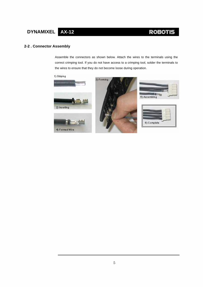
Assemble the connectors as shown below. Attach the wires to the terminals using the
correct crimping tool. If you do not have access to a crimping tool, solder the terminals to
the wires to ensure that they do not become loose during operation.
5

DYNAMIXEL AX-12
2-3. Dynamixel Wiring
Pin Assignment The connector pin assignments are as the following. The two connectors on the
Dynamixel are connected pin to pin, thus the AX-12 can be operated with only one
connector attached.
PIN2: VDD PIN1: GND
PIN3: Data
PIN1: GND PIN2: VDD
PIN3: Data
Wiring Connect the AX-2 actuators pin to pin as shown below. Many AX-12 actuators can be
controlled with a single bus in this manner.
Control Box “CM-5”
Main Controller To operate the Dynamixel actuators, the main controller must support TTL level half duplex
UART. A proprietary controller can be used, but the use of the Dynamixel controller CM-5
is recommended.
PC LINK A PC can be used to control the Dynamixel via the CM-5 controller.
PC Dynamixels CM-5
RS232 Level
TTL Level
6

DYNAMIXEL AX-12
bioloid A robot can be built using only the CM-5 controller and a number of AX-12 actuators. An
edutainment robotic kit named “Bioloid” is available which is based on the CM-5
controller and the AX-12 actuators.
For details, plea
Connection to UART To control the
signals to the h
below.
The power is su
and Pin 2 of th
explain the use
circuitry built in,
The direction o
DIRECTION_PO
DIRECTION_
CM-5 inte
An example of a robot built with Bioloid
se refer to the Bioloid manual.
Dynamixel actuators, the main controller needs to convert its UART
alf duplex type. The recommended circuit diagram for this is shown
pplied to the Dynamixel actuator from the main controller through Pin 1
e Molex3P connector. (The circuit shown above is presented only to
of half duplex UART. The CM-5 controller already has the above
thus the Dynamixel actuators can be directly connected to it)
f data signals on the TTL level TxD and RxD depends on the
RT level as the following.
DATA
TXD
RXD
74HC04
74HC126
PORT
rnal circuit (HALF DUPLEX UART)
10K
5V
DATA(PIN3)
9.6V VDD(PIN2) GND GND(PIN1)
74HC126
7

DYNAMIXEL AX-12
• When the DIRECTION_PORT level is High: the signal TxD is output as Data
• When the DIRECTION_PORT level is Low: the signal Data is input as RxD
Half Duplex UART A multi-drop method of connecting multiple Dynamixel actuators to a single node is
possible by using the half duplex UART. Thus a protocol that does not allow multiple
transmissions at the same time should be maintained when controlling the Dynamixel
actuators.
Main
Controller
[Multi Drop Link]
Caution Please ensure that the pin assignments are correct when connecting the Dynamixel
actuators. Check the current consumption when powering on. The current consumption
of a single Dynamixel actuator unit in standby mode should be no larger than 50mA
Connection Status Verification
When power is applied to the Dynamixel actuator, the LED blinks twice to confirm its
connection.
Inspection If the above operation was not successful, then check the connector pin assignment and
the voltage/current limit of the power supply.
8
DYNAMIXEL AX-12
3. Communication Protocol
3-1. Communication Overview
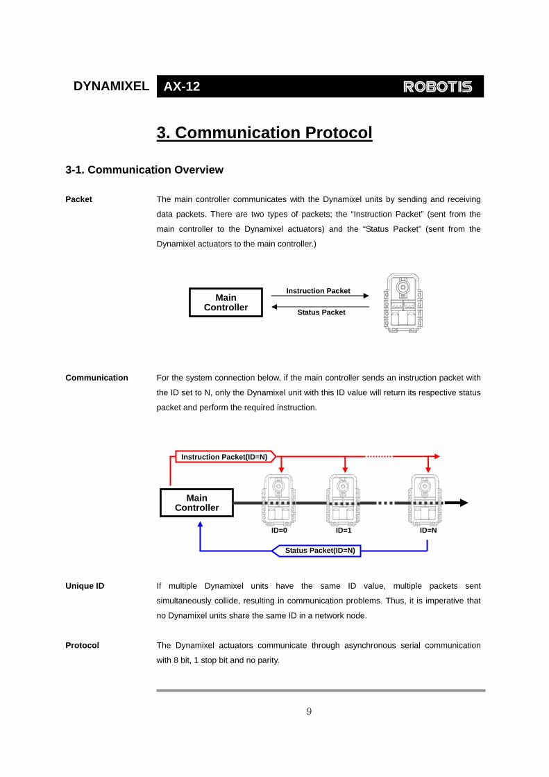
Packet The main controller communicates with the Dynamixel units by sending and receiving
data packets. There are two types of packets; the “Instruction Packet” (sent from the
main controller to the Dynamixel actuators) and the “Status Packet” (sent from the
Dynamixel actuators to the main controller.)
Communication For the system connection below, if the main controller sends an instruction packet with
the ID set to N, only the Dynamixel unit with this ID value will return its respective status
packet and perform the required instruction.
Unique ID If multiple Dynamixel units have the same ID value, multiple packets sent
simultaneously collide, resulting in communication problems. Thus, it is imperative that
no Dynamixel units share the same ID in a network node.
Protocol The Dynamixel actuators communicate through asynchronous serial communication
with 8 bit, 1 stop bit and no parity.
Instruction PacketMain
Controller Status Packet
ID=0 ID=1 ID=N
Main Controller
Instruction Packet(ID=N)
Status Packet(ID=N)
9

DYNAMIXEL AX-12
3-2. Instruction Packet
The Instruction Packet is the packet sent by the main controller to the Dynamixel units
to send commands. The structure of the Instruction Packet is as the following.
Instruction Packet OXFF 0XFF ID LENGTH INSTRUCTION PARAMETER1 …PARAMETER N CHECK SUM
The meanings of each packet byte definition are as the following.
0XFF 0XFF The two 0XFF bytes indicate the start of an incoming packet.
ID The unique ID of a Dynamixel unit. There are 254 available ID values, ranging from
0X00 to 0XFD.
Broadcasting ID ID 0XFE is the Broadcasting ID which indicates all of the connected Dynamixel units.
Packets sent with this ID apply to all Dynamixel units on the network. Thus packets sent
with a broadcasting ID will not return any status packets.
LENGTH The length of the packet where its value is “Number of parameters (N) + 2”
INSTRUCTION The instruction for the Dynamixel actuator to perform.
PARAMETER0…N Used if there is additional information needed to be sent other than the instruction itself.
CHECK SUM The computation method for the ‘Check Sum’ is as the following.
Check Sum = ~ (ID + Length + Instruction + Parameter1 + ... Parameter N)
If the calculated value is larger than 255, the lower byte is defined as the checksum
value.
~ represents the NOT logic operation.
3-3. Status Packet(Return Packet)
The Status Packet is the response packet from the Dynamixel units to the Main
Controller after receiving an instruction packet. The structure of the status packet is as
the following.
OXFF 0XFF ID LENGTH ERROR PARAMETER1 PARAMETER2…PARAMETER N CHECK SUM
10

DYNAMIXEL AX-12
The meanings of each packet byte definition are as the following.
0XFF 0XFF The two 0XFF bytes indicate the start of the packet.
ID The unique ID of the Dynamixel unit returning the packet. The initial value is set to 1.
LENGTH The length of the packet where its value is “Number of parameters (N) + 2”
ERROR The byte representing errors sent from the Dynamixel unit. The meaning of each bit is
as the following.
Bit Name Details
Bit 7 0 -
Bit 6 Instruction ErrorSet to 1 if an undefined instruction is sent or an action
instruction is sent without a Reg_Write instruction.
Bit 5 Overload ErrorSet to 1 if the specified maximum torque can't control the
applied load.
Bit 4 Checksum Error Set to 1 if the checksum of the instruction packet is incorrect.
Bit 3 Range Error Set to 1 if the instruction sent is out of the defined range.
Bit 2 Overheating
Error
Set to 1 if the internal temperature of the Dynamixel unit is
above the operating temperature range as defined in the
control table.
Bit 1 Angle Limit
Error
Set as 1 if the Goal Position is set outside of the range
between CW Angle Limit and CCW Angle
Limit.
Bit 0 Input Voltage
Error
Set to 1 if the voltage is out of the operating voltage range as
defined in the control table.
PARAMETER0…N Used if additional information is needed.
CHECK SUM The computation method for the ‘Check Sum’ is as the following.
Check Sum = ~ (ID + Length + Instruction + Parameter1 + ... Parameter N)
If the calculated value is larger than 255, the lower byte is defined as the checksum
value. ~ represents the NOT logic operation.
11

DYNAMIXEL AX-12
3-4. Control Table
Address Item Access Initial Value0(0X00) Model Number(L) RD 12(0x0C)1(0X01) Model Number(H) RD 0(0x00)2(0X02) Version of Firmware RD ?3(0X03) ID RD,W R 1(0x01)4(0X04) Baud Rate RD,W R 1(0x01)5(0X05) Return Delay T ime RD,W R 250(0xFA)6(0X06) CW Angle Lim it(L) RD,W R 0(0x00)7(0X07) CW Angle Lim it(H) RD,W R 0(0x00)8(0X08) CCW Angle Lim it(L) RD,W R 255(0xFF)9(0X09) CCW Angle Lim it(H) RD,W R 3(0x03)10(0x0A) (Reserved) - 0(0x00)11(0X0B) the Highest Lim it Temperature RD,W R 85(0x55)12(0X0C) the Lowest Lim it Voltage RD,W R 60(0X3C)13(0X0D) the Highest Lim it Voltage RD,W R 190(0xBE)14(0X0E) Max Torque(L) RD,W R 255(0XFF)15(0X0F) Max Torque(H) RD,W R 3(0x03)16(0X10) Status Return Level RD,W R 2(0x02)17(0X11) Alarm LED RD,W R 4(0x04)18(0X12) Alarm Shutdown RD,W R 4(0x04)19(0X13) (Reserved) RD,W R 0(0x00)20(0X14) Down Calibration(L) RD ?21(0X15) Down Calibration(H) RD ?22(0X16) Up Calibration(L) RD ?23(0X17) Up Calibration(H) RD ?24(0X18) Torque Enable RD,W R 0(0x00)25(0X19) LED RD,W R 0(0x00)26(0X1A) CW Compliance Margin RD,W R 0(0x00)27(0X1B) CCW Compliance Margin RD,W R 0(0x00)28(0X1C) CW Compliance Slope RD,W R 32(0x20)29(0X1D) CCW Compliance Slope RD,W R 32(0x20)30(0X1E) Goal Position(L) RD,W R [Addr36]value31(0X1F) Goal Position(H) RD,W R [Addr37]value32(0X20) Moving Speed(L) RD,W R 033(0X21) Moving Speed(H) RD,W R 034(0X22) Torque Lim it(L) RD,W R [Addr14] value35(0X23) Torque Lim it(H) RD,W R [Addr15] value36(0X24) Present Position(L) RD ?37(0X25) Present Position(H) RD ?38(0X26) Present Speed(L) RD ?39(0X27) Present Speed(H) RD ?40(0X28) Present Load(L) RD ?41(0X29) Present Load(H) RD ?42(0X2A) Present Voltage RD ?43(0X2B) Present Temperature RD ?44(0X2C) Registered Instruction RD,W R 0(0x00)45(0X2D) (Reserved) - 0(0x00)46[0x2E) Moving RD 0(0x00)47[0x2F) Lock RD,W R 0(0x00)48[0x30) Punch(L) RD,W R 32(0x20)49[0x31) Punch(H) RD,W R 0(0x00)
EEPROM Area
RAM Area
12

DYNAMIXEL AX-12
Control Table The Control Table contains information on the status and operation of the Dynamixel
actuator. The Dynamixel actuator is operated by writing values to its control table and its
status is checked by reading values off its control table.
RAM and EEPROM The data values for the RAM area will be set to the default initial values whenever the
power is turned on. However, the data values for the EEPROM area are non-volatile
and will still remain even after the power is turned off.
Initial Value The Initial Value column on the right side of the control table shows the Factory Default
Values for the case of EEPROM area data, and shows the initial value when the power
is turned on for the case of RAM area data.
The following explains the meaning of data stored in each of the addresses in the
control table.
Address 0x00,0x01 Model Number. For AX-12, this value is 0X000C (12).
Address 0x02 Firmware Version.
Address 0x03 ID. The unique ID number assigned to each Dynamixel actuators for identifying them.
Different IDs are required for each Dynamixel actuators that are on the same network.
Address 0x04 Baud Rate. Determines the communication speed. The computation is done by the
following formula.
Speed (BPS) = 2000000 / (Address4 + 1)
Data Value for each Major Baud Rate
Adress4 Hex Set BPS Goal BPS Error1 0X01 1000000.0 1000000.0 0.000%3 0X03 500000.0 500000.0 0.000%4 0X04 400000.0 400000.0 0.000%7 0X07 250000.0 250000.0 0.000%9 0X09 200000.0 200000.0 0.000%
16 0X10 117647.1 115200.0 -2.124%34 0X22 57142.9 57600.0 0.794%
103 0X67 19230.8 19200.0 -0.160%207 0XCF 9615.4 9600.0 -0.160%
Note A maximum Baud Rate error of 3% is within the tolerance of UART communication.
Caution The initial value of Baudrate is set to 1(1000000bps)
13

DYNAMIXEL AX-12
Address 0x05 Return Delay Time. The time it takes for the Status Packet to return after the Instruction
Packet is sent. The delay time is given by 2uSec * Address5 value.
Address 0x06,0x07,0x08,0x09
Operating Angle Limit. Sets the Dynamixel actuator’s operating angle range. The Goal
Position needs to be within the range of: CW Angle Limit <= Goal Position <= CCW
Angle Limit. An Angle Limit Error will occur if the Goal Position is set outside this range
set by the operating angle limits.
Address 0x0B the Highest Limit Temperature. The upper limit of the Dynamixel actuator’s operating
temperature. If the internal temperature of the Dynamixel actuator gets higher than this
value, the Over Heating Error Bit (Bit 2 of the Status Packet) will return the value 1, and
an alarm will be set by Address 17, 18. The values are in Degrees Celsius.
Address 0x0C,0x0D the Lowest (Highest) Limit Voltage. The upper and lower limits of the Dynamixel
actuator’s operating voltage. If the present voltage (Address 42) is out of the specified
range, a Voltage Range Error Bit (Bit 0 of the Status Packet) will return the value 1,
and an alarm will be set by Address 17, 18. The values are 10 times the actual voltage
value. For example, if the Address 12 value is 80, then the lower voltage limit is set to
8V.
Address 0x0E,0x0F, 0x22,0x23
Max Torque. The maximum torque output for the Dynamixel actuator. When this value
is set to 0, the Dynamixel actuator enters the Free Run mode. There are two locations
where this maximum torque limit is defined; in the EEPROM (Address 0X0E, 0x0F) and
in the RAM (Address 0x22, 0x23). When the power is turned on, the maximum torque
limit value defined in the EEPROM is copied to the location in the RAM. The torque of
the Dynamixel actuator is limited by the values located in the RAM (Address 0x22,
0x23).
Address 0X10 Status Return Level. Determines whether the Dynamixel actuator will return a Status
Packet after receiving an Instruction Packet.
Address16 Returning the Status Packet
0 Do not respond to any instructions
1 Respond only to READ_DATA instructions
2 Respond to all instructions
14
DYNAMIXEL AX-12
In the case of an instruction which uses the Broadcast ID (0XFE) the Status Packet will
not be returned regardless of the Address 0x10 value.
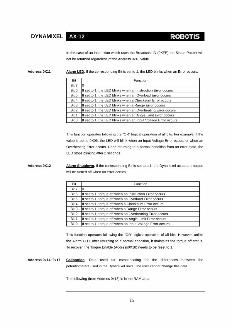
Address 0X11 Alarm LED. If the corresponding Bit is set to 1, the LED blinks when an Error occurs.
Bit Function
Bit 7 0Bit 6 If set to 1, the LED blinks when an Instruction Error occursBit 5 If set to 1, the LED blinks when an Overload Error occursBit 4 If set to 1, the LED blinks when a Checksum Error occursBit 3 If set to 1, the LED blinks when a Range Error occursBit 2 If set to 1, the LED blinks when an Overheating Error occursBit 1 If set to 1, the LED blinks when an Angle Limit Error occursBit 0 If set to 1, the LED blinks when an Input Voltage Error occurs
This function operates following the “OR” logical operation of all bits. For example, if the
value is set to 0X05, the LED will blink when an Input Voltage Error occurs or when an
Overheating Error occurs. Upon returning to a normal condition from an error state, the
LED stops blinking after 2 seconds.
Address 0X12 Alarm Shutdown. If the corresponding Bit is set to a 1, the Dynamixel actuator’s torque
will be turned off when an error occurs.
Bit Function
Bit 7 0Bit 6 If set to 1, torque off when an Instruction Error occurs Bit 5 If set to 1, torque off when an Overload Error occurs Bit 4 If set to 1, torque off when a Checksum Error occurs Bit 3 If set to 1, torque off when a Range Error occurs Bit 2 If set to 1, torque off when an Overheating Error occurs Bit 1 If set to 1, torque off when an Angle Limit Error occurs Bit 0 If set to 1, torque off when an Input Voltage Error occurs
This function operates following the “OR” logical operation of all bits. However, unlike
the Alarm LED, after returning to a normal condition, it maintains the torque off status.
To recover, the Torque Enable (Address0X18) needs to be reset to 1.
Address 0x14~0x17 Calibration. Data used for compensating for the differences between the
potentiometers used in the Dynamixel units. The user cannot change this data.
The following (from Address 0x18) is in the RAM area.
15

DYNAMIXEL AX-12
Address 0x18 Torque Enable. When the power is first turned on, the Dynamixel actuator enters the
Torque Free Run condition (zero torque). Setting the value in Address 0x18 to 1 enables
the torque.
Address 0x19 LED. The LED turns on when set to 1 and turns off if set to 0.
Address 0x1A~0x1D Compliance Margin and Slope. The compliance of the Dynamixel actuator is defined
by setting the compliance Margin and Slope. This feature can be utilized for absorbing
shocks at the output shaft. The following graph shows how each compliance value
(length of A, B, C & D) is defined by the Position Error and applied torque.
A : CCW ComplianB : CCW ComplianC : CW ComplianceD : CW ComplianceE : Punch(Address
Address 0X1E,0x1F Goal Position Requested angul
Setting this value to 0x3ff moves
(Goa
(Goal Position =
Goal Position
E
ce Slope(Address0x1D) ce Margin(Address0x1B) Margin(Address0x1A) Slope (Address0x1C)
0x30,31)
ar position for the Dynamixel actua
the output shaft to the position at
l P )
300~360°
Invalid Angle
16
CW
CCWCW
CCW
B A C DX axis:Position Error
Y axis:Output Torque
E
tor output to move to.
300°.
0° (Goal Position = 0)300° 0x3ff)
150° osition = 0x1ff
DYNAMIXEL AX-12
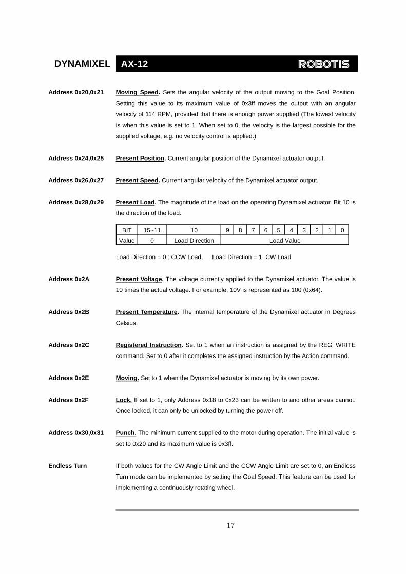
Address 0x20,0x21 Moving Speed. Sets the angular velocity of the output moving to the Goal Position.
Setting this value to its maximum value of 0x3ff moves the output with an angular
velocity of 114 RPM, provided that there is enough power supplied (The lowest velocity
is when this value is set to 1. When set to 0, the velocity is the largest possible for the
supplied voltage, e.g. no velocity control is applied.)
Address 0x24,0x25 Present Position. Current angular position of the Dynamixel actuator output.
Address 0x26,0x27 Present Speed. Current angular velocity of the Dynamixel actuator output.
Address 0x28,0x29 Present Load. The magnitude of the load on the operating Dynamixel actuator. Bit 10 is
the direction of the load.
BIT 15~11 10 9 8 7 6 5 4 3 2 1 0
Value 0 Load Direction Load Value
Load Direction = 0 : CCW Load, Load Direction = 1: CW Load
Address 0x2A Present Voltage. The voltage currently applied to the Dynamixel actuator. The value is
10 times the actual voltage. For example, 10V is represented as 100 (0x64).
Address 0x2B Present Temperature. The internal temperature of the Dynamixel actuator in Degrees
Celsius.
Address 0x2C Registered Instruction. Set to 1 when an instruction is assigned by the REG_WRITE
command. Set to 0 after it completes the assigned instruction by the Action command.
Address 0x2E Moving. Set to 1 when the Dynamixel actuator is moving by its own power.
Address 0x2F Lock. If set to 1, only Address 0x18 to 0x23 can be written to and other areas cannot.
Once locked, it can only be unlocked by turning the power off.
Address 0x30,0x31 Punch. The minimum current supplied to the motor during operation. The initial value is
set to 0x20 and its maximum value is 0x3ff.
Endless Turn If both values for the CW Angle Limit and the CCW Angle Limit are set to 0, an Endless
Turn mode can be implemented by setting the Goal Speed. This feature can be used for
implementing a continuously rotating wheel.
17

DYNAMIXEL AX-12
Goal Speed Setting
BIT 15~11 10 9 8 7 6 5 4 3 2 1 0
Value 0 Turn Direction Speed Value
Turn Direction = 0 : CCW Direction Turn, Load Direction = 1: CW Direction Turn
Range Each data has a valid minimum and maximum values. Write instructions made outside
of these valid ranges will return an error. The following table summarizes the data range
for each register. 16 bit data registers are indicated with two bytes (L) and (H). Both
bytes need to be written at the same time as one instruction packet.
Write
Address Writing Item Length(bytes) Min Max
3(0X03) ID 1 0 253(0xfd)4(0X04) Baud Rate 1 0 254(0xfe)5(0X05) Return Delay Time 1 0 254(0xfe)6(0X06) CW Angle Limit 2 0 1023(0x3ff)8(0X08) CCW Angle Limit 2 0 1023(0x3ff)
11(0X0B) the Highest Limit Temperature 1 0 150(0x96)12(0X0C) the Lowest Limit Voltage 1 50(0x32) 250(0xfa)13(0X0D) the Highest Limit Voltage 1 50(0x32) 250(0xfa)14(0X0E) Max Torque 2 0 1023(0x3ff)16(0X10) Status Return Level 1 0 217(0X11) Alarm LED 1 0 127(0x7f)18(0X12) Alarm Shutdown 1 0 127(0x7f)19(0X13) (Reserved) 1 0 124(0X18) Torque Enable 1 0 125(0X19) LED 1 0 126(0X1A) CW Compliance Margin 1 0 254(0xfe)27(0X1B) CCW Compliance Margin 1 0 254(0xfe)28(0X1C) CW Compliance Slope 1 1 254(0xfe)29(0X1D) CCW Compliance Slope 1 1 254(0xfe)30(0X1E) Goal Position 2 0 1023(0x3ff)32(0X20) Moving Speed 2 0 1023(0x3ff)34(0X22) Torque Limit 2 0 1023(0x3ff)44(0X2C) Registered Instruction 1 0 147(0X2F) Lock 1 1 148(0X30) Punch 2 0 1023(0x3ff)
[Control Table Data Range and Length for Writing]
18

DYNAMIXEL AX-12
4. Instruction Set and Examples
The following Instructions are available.
Instruction Function Value Number of
Parameter
PING No action. Used for obtaining a Status Packet 0x01 0
READ DATA Reading values in the Control Table 0x02 2
W RITE DATA W riting values to the Control Table 0x03 2 ~
REG W RITE Similar to W RITE_DATA, but stays in standbymode until the ACION instruction is given 0x04 2 ~
ACTION Triggers the action registered by theREG_W RITE instruction 0x05 0
RESETChanges the control table values of theDynamixel actuator to the Factory Default Valuesettings
0x06 0
SYNC W RITE Used for controlling many Dynamixel actuatorsat the same time 0x83 4~
4-1. WRITE_DATA
Function To write data into the control table of the Dynamixel actuator
Length N+3 (N is the number of data to be written)
Instruction 0X03
Parameter1 Starting address of the location where the data is to be written
Parameter2 1st data to be written
Parameter3 2nd data to be written
Parameter N+1 Nth data to be written
Example 1 Setting the ID of a connected Dynamixel actuator to 1
Write 1 to address 3 of the control table. The ID is transmitted using the Broadcasting ID
(0xFE).
19
DYNAMIXEL AX-12
Instruction Packet : 0XFF 0XFF 0XFE 0X04 0X03 0X03 0X01 0XF6`
ID LENGTH INSTRUCTION PARAMETERS CHECKSUM
Because it was transmitted with a Broadcast ID (0XFE), no status packets are returned.
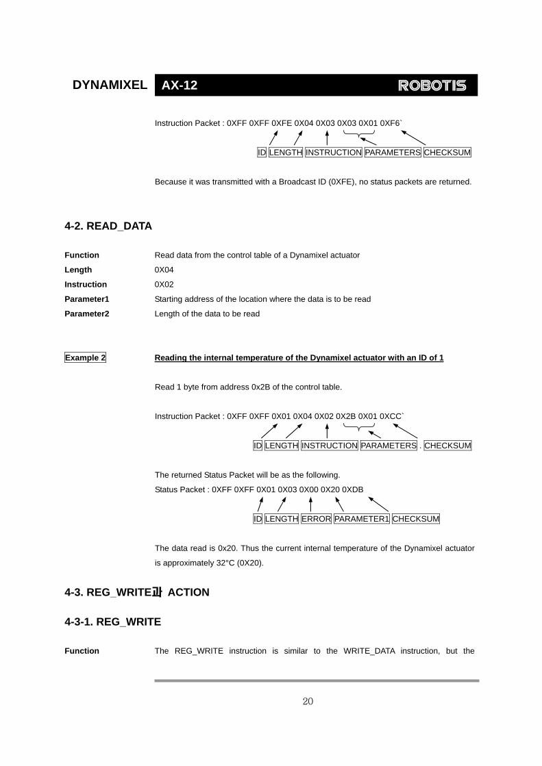
4-2. READ_DATA
Function Read data from the control table of a Dynamixel actuator
Length 0X04
Instruction 0X02
Parameter1 Starting address of the location where the data is to be read
Parameter2 Length of the data to be read
Example 2 Reading the internal temperature of the Dynamixel actuator with an ID of 1
Read 1 byte from address 0x2B of the control table.
Instruction Packet : 0XFF 0XFF 0X01 0X04 0X02 0X2B 0X01 0XCC`
ID LENGTH INSTRUCTION PARAMETERS . CHECKSUM
The returned Status Packet will be as the following.
Status Packet : 0XFF 0XFF 0X01 0X03 0X00 0X20 0XDB
ID LENGTH ERROR PARAMETER1 CHECKSUM
The data read is 0x20. Thus the current internal temperature of the Dynamixel actuator
is approximately 32°C (0X20).
4-3. REG_WRITE과 ACTION 4-3-1. REG_WRITE Function The REG_WRITE instruction is similar to the WRITE_DATA instruction, but the
20

DYNAMIXEL AX-12
execution timing is different. When the Instruction Packet is received the values are
stored in the Buffer and the Write instruction is under a standby status. At this time, the
Registered Instruction register (Address 0x2C) is set to 1. After the Action Instruction
Packet is received, the registered Write instruction is finally executed.
Length N+3 (N is the number of data to be written)
Instruction 0X04
Parameter1 Starting address of the location where the data is to be written
Parameter2 1st data to be written
Parameter3 2nd data to be written
Parameter N+1 Nth data to be written
4-3-2. ACTION
Function Triggers the action registered by the REG_WRITE instruction
Length 0X02
Instruction 0X05
Parameter NONE
The ACTION instruction is useful when multiple Dynamixel actuators need to move
simultaneously. When controlling multiple Dynamixel actuator units, slight time delays
can occur between the 1st and last units to receive an instruction. The Dynamixel
actuator handles this problem by using the ACTION instruction.
Broadcasting The Broadcast ID (0XFE) is used when sending ACTION instructions to more than two
Dynamixel actuators. Note that no packets are returned by this operation.
4-4. PING
Function Does not command any operations. Used for requesting a status packet or to check the
existence of a Dynamixel actuator with a specific ID.
Length 0X02
Instruction 0X01
Parameter NONE
21

DYNAMIXEL AX-12
Example 3 Obtaining the status packet of the Dynamixel actuator with an ID of 1
Instruction Packet : 0XFF 0XFF 0X01 0X02 0X01 0XFB`
ID LENGTH INSTRUCTION CHECKSUM
The returned Status Packet is as the following
Status Packet : 0XFF 0XFF 0X01 0X02 0X00 0XFC
ID LENGTH ERROR CHECKSUM
Regardless of whether the Broadcasting ID is used or the Status Return Level (Address
16) is 0, a Status Packet is always returned by the PING instruction.
4-5. RESET
Function Changes the control table values of the Dynamixel actuator to the Factory Default Value
settings
Length 0X02
Instruction 0X06
Parameter NONE
Example 4 Resetting the Dynamixel actuator with an ID of 0
Instruction Packet : 0XFF 0XFF 0X00 0X02 0X06 0XF7`
ID LENGTH INSTRUCTION CHECKSUM
The returned Status Packet is as the following
Status Packet : 0XFF 0XFF 0X00 0X02 0X00 0XFD
ID LENGTH ERROR CHECKSUM
Note the ID of this Dynamixel actuator is now changed to 1 after the RESET instruction.
22

DYNAMIXEL AX-12
4-6. SYNC WRITE
Function Used for controlling many Dynamixel actuators at the same time. The communication
time decreases by the Synch Write instruction since many instructions can be
transmitted by a single instruction. However, you can use this instruction only when the
lengths and addresses of the control table to be written to are the same. Also, the
broadcasting ID needs to be used for transmitting.
ID 0XFE
Length (L + 1) * N + 4 (L: Data length for each Dynamixel actuator, N: The number of Dynamixel
actuators)
Instruction 0X83
Parameter1 Starting address of the location where the data is to be written
Parameter2 The length of the data to be written (L)
Parameter3 The ID of the 1st Dynamixel actuator
Parameter4 The 1st data for the 1st Dynamixel actuator
Parameter5 The 2nd data for the 1st Dynamixel actuator Data for the 1st Dynamixel actuator … Parameter L+3 The Lth data for the 1st Dynamixel actuator
Parameter L+4 The ID of the 2nd Dynamixel actuator
Parameter L+5 The 1st data for the 2nd Dynamixel actuator Data for the 2nd Dynamixel actuatorParameter L+6 The 2nd data for the 2nd Dynamixel actuator …
Parameter 2L+4 The Lth data for the 2nd Dynamixel actuator
….
Example 5 Setting the following positions and velocities for 4 Dynamixel actuators
Dynamixel actuator with an ID of 0: to position 0X010 with a speed of 0X150
Dynamixel actuator with an ID of 1: to position 0X220 with a speed of 0X360
Dynamixel actuator with an ID of 2: to position 0X030 with a speed of 0X170
Dynamixel actuator with an ID of 0: to position 0X220 with a speed of 0X380
Instruction Packet : 0XFF 0XFF 0XFE 0X18 0X83 0X1E 0X04 0X00 0X10 0X00 0X50
0X01 0X01 0X20 0X02 0X60 0X03 0X02 0X30 0X00 0X70 0X01 0X03 0X20 0X02 0X80
0X03 0X12
No status packets are returned since the Broadcasting ID was used.
23

DYNAMIXEL AX-12
5. Example For the following examples, we assume a Dynamixel actuator with an ID of 1 in Reset
status and that the Baud rate is 57142 BPS.
Example 6 Reading the Model Number and Firmware Version of the Dynamixel actuator with
an ID of 1
Instruction Packet Instruction = READ_DATA, Address = 0x00, Length = 0x03 Communication ->[Dynamixel]:FF FF 01 04 02 00 03 F5 (LEN:008) <-[Dynamixel]:FF FF 01 05 00 74 00 08 7D (LEN:009) Status Packet Result Model Number = 116 (0x74) (for the case of DX-116) Firmware Version = 0x08
Example 7 Changing the ID to 0 for a Dynamixel actuator with an ID of 1
Instruction Packet Instruction = WRITE_DATA, Address = 0x03, DATA = 0x00 Communication ->[Dynamixel]:FF FF 01 04 03 03 00 F4 (LEN:008) <-[Dynamixel]:FF FF 01 02 00 FC (LEN:006)
Status Packet Result NO ERROR
Example 8 Changing the Baud Rate of a Dynamixel actuator to 1M bps
Instruction Packet Instruction = WRITE_DATA, Address = 0x04, DATA = 0x01 Communication ->[Dynamixel]:FF FF 00 04 03 04 01 F3 (LEN:008) <-[Dynamixel]:FF FF 00 02 00 FD (LEN:006)
Status Packet Result NO ERROR
Example 9 Resetting the Return Delay Time to 4 uSec for a Dynamixel actuator with an ID of
0
A Return Delay Time Value of 1 corresponds to 2uSec.
24

DYNAMIXEL AX-12
Instruction Packet Instruction = WRITE_DATA, Address = 0x05, DATA = 0x02 Communication ->[Dynamixel]:FF FF 00 04 03 05 02 F1 (LEN:008) <-[Dynamixel]:FF FF 00 02 00 FD (LEN:006)
Status Packet Result NO ERROR
It is recommended to set the Return Delay Time to the minimum value allowed by the
Main Controller.
Example 10 Limiting the operating angle range to 0°~150° for a Dynamixel actuator with an ID
of 0 Since the CCW Angle Limit of 0x3ff corresponds to 300°, the angle 150° is represented by the value 0x1ff
Instruction Packet Instruction = WRITE_DATA, Address = 0x08, DATA = 0xff, 0x01 Communication ->[Dynamixel]:FF FF 00 05 03 08 FF 01 EF (LEN:009) <-[Dynamixel]:FF FF 00 02 00 FD (LEN:006)
Status Packet Result NO ERROR
Example 11 Resetting the upper limit for the operating temperature to 80°C for a Dynamixel
actuator with an ID of 0
Instruction Packet Instruction = WRITE_DATA, Address = 0x0B, DATA = 0x50 Communication ->[Dynamixel]:FF FF 00 04 03 0B 50 9D (LEN:008) <-[Dynamixel]:FF FF 00 02 00 FD (LEN:006)
Status Packet Result NO ERROR
Example 12 Setting the operating voltage to 10V ~ 17V for a Dynamixel actuator with an ID of 0
10V is represented by 100 (0x64), and 17V by 170 (0xAA). Instruction Packet Instruction = WRITE_DATA, Address = 0x0C, DATA = 0x64, 0xAA Communication ->[Dynamixel]:FF FF 00 05 03 0C 64 AA DD (LEN:009) <-[Dynamixel]:FF FF 00 02 00 FD (LEN:006)
Status Packet Result NO ERROR
25

DYNAMIXEL AX-12
Example 13 Setting the maximum torque to 50% of its maximum possible value for a
Dynamixel actuator with an ID of 0
Set the MAX Torque value located in the ROM area to 0x1ff which is 50% of the
maximum value 0x3ff. Instruction Packet Instruction = WRITE_DATA, Address = 0x0E, DATA = 0xff, 0x01 Communication ->[Dynamixel]:FF FF 00 05 03 0E FF 01 E9 (LEN:009) <-[Dynamixel]:FF FF 00 02 00 FD (LEN:006)
Status Packet Result NO ERROR
To verify the effect of the adjusted Max Torque value, the power needs to be turned off
and then on.
Example 14 Set the Dynamixel actuator with an ID of 0 to never return a Status Packet
Instruction Packet Instruction = WRITE_DATA, Address = 0x10, DATA = 0x00 Communication ->[Dynamixel]:FF FF 00 04 03 10 00 E8 (LEN:008) <-[Dynamixel]:FF FF 00 02 00 FD (LEN:006)
Status Packet Result NO ERROR
The Status Packet is not returned starting with the following instruction.
Example 15 Set the Alarm to blink the LED and Shutdown (Torque off) the actuator when the
operating temperature goes over the set limit
Since the Overheating Error is Bit 2, set the Alarm value to 0x04. Instruction Packet Instruction = WRITE_DATA, Address = 0x11, DATA = 0x04, 0x04 Communication ->[Dynamixel]:FF FF 00 05 03 11 04 04 DE (LEN:009) <-[Dynamixel]:FF FF 00 02 00 FD (LEN:006)
Status Packet Result NO ERROR
Example 16 Turn on the LED and Enable Torque for a Dynamixel actuator with an ID of 0
Instruction Packet Instruction = WRITE_DATA, Address = 0x18, DATA = 0x01, 0x01
26
DYNAMIXEL AX-12
Communication ->[Dynamixel]:FF FF 00 05 03 18 01 01 DD (LEN:009) <-[Dynamixel]:FF FF 00 02 00 FD (LEN:006)
Status Packet Result NO ERROR
You can verify the Torque Enabled status by trying to move the output of the actuator by
hand.
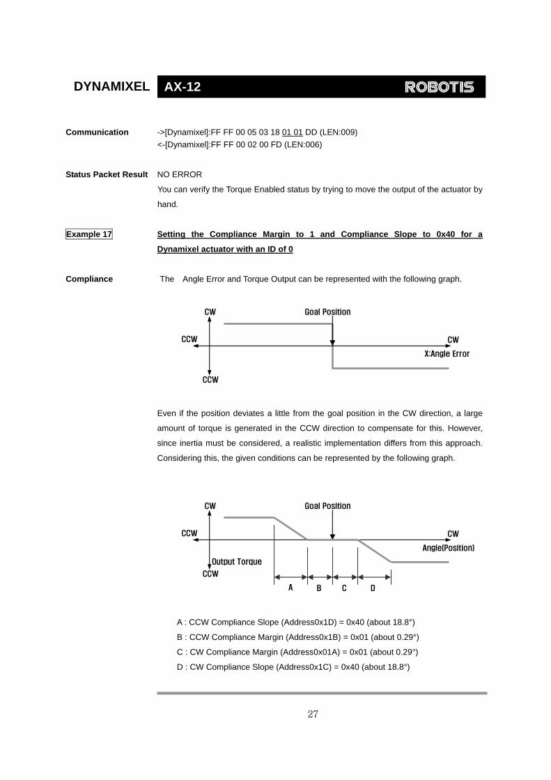
Example 17 Setting the Compliance Margin to 1 and Compliance Slope to 0x40 for a
Dynamixel actuator with an ID of 0
Compliance The Angle Error and Torque Output can be represented with the following graph.
CCW
X:Angle Error
CW
Goal Position CW
CCW
Even if the position deviates a little from the goal position in the CW direction, a large
amount of torque is generated in the CCW direction to compensate for this. However,
since inertia must be considered, a realistic implementation differs from this approach.
Considering this, the given conditions can be represented by the following graph.
CW Goal Position
Output Torque
Angle(Position)
D C A B
CCW CW
CCW
A : CCW Compliance Slope (Address0x1D) = 0x40 (about 18.8°)
B : CCW Compliance Margin (Address0x1B) = 0x01 (about 0.29°)
C : CW Compliance Margin (Address0x01A) = 0x01 (about 0.29°)
D : CW Compliance Slope (Address0x1C) = 0x40 (about 18.8°)
27

DYNAMIXEL AX-12
Instruction Packet Instruction = WRITE_DATA, Address = 0x1A, DATA = 0x01, 0x01, 0x40, 0x40 Communication ->[Dynamixel]:FF FF 00 07 03 1A 01 01 40 40 59 (LEN:011) <-[Dynamixel]:FF FF 00 02 00 FD (LEN:006)
Status Packet Result NO ERROR
The Compliance Slope takes effect with discrete steps of 2n (n is integer). Thus any
Compliance value between 0x11 and 0x20 has identical effects.
Example 18 Position the output of a Dynamixel actuator with an ID of 0 to 180° with an angular
velocity of 057RPM
Set Address 0x1E (Goal Position) to 0x200 and Address 0x20 (Moving Speed) to 0x200.
Instruction Packet Instruction = WRITE_DATA, Address = 0x1E, DATA = 0x00, 0x02, 0x00, 0x02 Communication ->[Dynamixel]:FF FF 00 07 03 1E 00 02 00 02 D3 (LEN:011) <-[Dynamixel]:FF FF 00 02 00 FD (LEN:006)
Status Packet Result NO ERROR
Example 19 Position the output of a Dynamixel actuator with an ID of 0 to 0° and Position the
output of a Dynamixel actuator with an ID of 1 to 300°, and initiate the movement
at the same time.
If the WRITE_DATA is used, the movement of the two actuators cannot be initiate at the
same time, thus the REG_WRITE and ACTION instructions should be used instead. Instruction Packet ID=0, Instruction = REG_WRITE, Address = 0x1E, DATA = 0x00, 0x00 ID=1, Instruction = REG_WRITE, Address = 0x1E, DATA = 0xff, 0x03 ID=0xfe(Broadcasting ID), Instruction = ACTION, Communication ->[Dynamixel]:FF FF 00 05 04 1E 00 00 D8 (LEN:009) <-[Dynamixel]:FF FF 00 02 00 FD (LEN:006) ->[Dynamixel]:FF FF 01 05 04 1E FF 03 D5 (LEN:009) <-[Dynamixel]:FF FF 01 02 00 FC (LEN:006) ->[Dynamixel]:FF FF FE 02 05 FA (LEN:006) <-[Dynamixel]: //No return packet against broadcasting ID
Status Packet Result NO ERROR
28

DYNAMIXEL AX-12
Example 20 Lock all addresses except for Address 0x18 ~ Address0x23 for a Dynamixel
actuator with an ID of 0
Set Address 0x2F (Lock) to 1. Instruction Packet Instruction = WRITE_DATA, Address = 0x2F, DATA = 0x01 Communication ->[Dynamixel]:FF FF 00 04 03 2F 01 C8 (LEN:008) <-[Dynamixel]:FF FF 00 02 00 FD (LEN:006)
Status Packet Result NO ERROR
Once locked, the only way to unlock it is to remove the power.
If an attempt is made to access any locked data, an error is returned.
->[Dynamixel]:FF FF 00 05 03 30 40 00 87 (LEN:009)
<-[Dynamixel]:FF FF 00 02 08 F5 (LEN:006)
Range Error
Example 21 Set the minimum power (Punch) to 0x40 for a Dynamixel actuator with an ID of 0 Instruction Packet Instruction = WRITE_DATA, Address = 0x30, DATA = 0x40, 0x00 Communication ->[Dynamixel]:FF FF 00 05 03 30 40 00 87 (LEN:009) <-[Dynamixel]:FF FF 00 02 00 FD (LEN:006)
Status Packet Result NO ERROR
29

DYNAMIXEL AX-12
Appendix Half duplex UART Half duplex UART is a serial communication protocol where both TxD and RxD cannot
be used at the same time. This method is generally used when many devices need to
be connected to a single bus. Since more than one device are connected to the same
bus, all the other devices need to be in input mode while one device is transmitting. The
Main Controller that controllers the Dynamixel actuators sets the communication
direction to input mode, and only when it is transmitting an Instruction Packet, it
changes the direction to output mode.
Instruction Packet Status Packet
Return Delay Time
RS485 Direction Output Duration
Return Delay Time The time it takes for the Dynamixel actuator to return the Status Packet after receiving
an Instruction Packet. The Default Value is 160 uSec and can be changed via the
Control Table at Address 5. The Main Controller needs to change the Direction Port to
input mode during the Return Delay Time after sending an instruction packet.
Tx,Rx Direction For Half Duplex UART, the transmission ending timing is important to change the
direction to receiving mode. The bit definitions within the register that indicates UART_STATUS are as the following
TXD_BUFFER_READY_BIT: Indicates that the transmission DATA can be loaded into
the Buffer. Note that this only means that the SERIAL TX BUFFER is empty, and does
not necessarily mean that the all the data transmitted before has left the CPU.
TXD_SHIFT_REGISTER_EMPTY_BIT: Set when all the Transmission Data has
completed its transmission and left the CPU.
The TXD_BUFFER_READY_BIT is used when one byte is to be transmitted via the
serial communication channel, and an example is shown below. TxDByte(byte bData) { while(!TXD_BUFFER_READY_BIT); //wait until data can be loaded. SerialTxDBuffer = bData; //data load to TxD buffer }
30
DYNAMIXEL AX-12
When changing the direction, the TXD_SHIFT_REGISTER_EMPTY_BIT must be
checked.
The following is an example program that sends an Instruction Packet.
LINE 1 DIRECTION_PORT = TX_DIRECTION; LINE 2 TxDByte(0xff); LINE 3 TxDByte(0xff); LINE 4 TxDByte(bID); LINE 5 TxDByte(bLength); LINE 6 TxDByte(bInstruction); LINE 7 TxDByte(Parameter0); TxDByte(Parameter1); … LINE 8 DisableInterrupt(); // interrupt should be disable LINE 9 TxDByte(Checksum); //last TxD LINE 10 while(!TXD_SHIFT_REGISTER_EMPTY_BIT); //Wait till last data bit has been sent LINE 11 DIRECTION_PORT = RX_DIRECTION; //Direction change to RXD LINE 12 EnableInterrupt(); // enable interrupt again
Please note the important lines between LINE 8 and LINE 12. Line 8 is necessary since
an interrupt here may cause a delay longer than the return delay time and corruption to
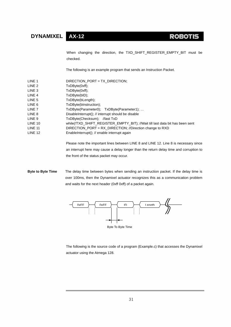
the front of the status packet may occur. Byte to Byte Time The delay time between bytes when sending an instruction packet. If the delay time is
over 100ms, then the Dynamixel actuator recognizes this as a communication problem
and waits for the next header (0xff 0xff) of a packet again.
0xFF 0xFF ID Length Byte To Byte Time
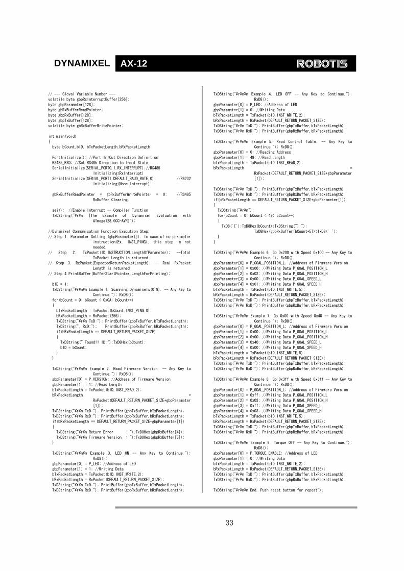
The following is the source code of a program (Example.c) that accesses the Dynamixel
actuator using the Atmega 128.
31

DYNAMIXEL AX-12
C Language Example : Dinamixel access with Atmega128
/*
* The Example of Dynamixel Evaluation with Atmega128
* Date : 2005.5.11
* Author : BS KIM
*/
/*
* included files
*/
#define ENABLE_BIT_DEFINITIONS
//#include <io.h>
#include <inttypes.h>
#include <avr/io.h>
#include <avr/interrupt.h>
#include <avr/signal.h>
#define cbi(REG8,BITNUM) REG8 &= ~(_BV(BITNUM))
#define sbi(REG8,BITNUM) REG8 |= _BV(BITNUM)
typedef unsigned char byte;
typedef unsigned int word;
#define ON 1
#define OFF 0
#define _ON 0
#define _OFF 1
//--- Control Table Address ---
//EEPROM AREA
#define P_MODEL_NUMBER_L 0
#define P_MODOEL_NUMBER_H 1
#define P_VERSION 2
#define P_ID 3
#define P_BAUD_RATE 4
#define P_RETURN_DELAY_TIME 5
#define P_CW_ANGLE_LIMIT_L 6
#define P_CW_ANGLE_LIMIT_H 7
#define P_CCW_ANGLE_LIMIT_L 8
#define P_CCW_ANGLE_LIMIT_H 9
#define P_SYSTEM_DATA2 10
#define P_LIMIT_TEMPERATURE 11
#define P_DOWN_LIMIT_VOLTAGE 12
#define P_UP_LIMIT_VOLTAGE 13
#define P_MAX_TORQUE_L 14
#define P_MAX_TORQUE_H 15
#define P_RETURN_LEVEL 16
#define P_ALARM_LED 17
#define P_ALARM_SHUTDOWN 18
#define P_OPERATING_MODE 19
#define P_DOWN_CALIBRATION_L 20
#define P_DOWN_CALIBRATION_H 21
#define P_UP_CALIBRATION_L 22
#define P_UP_CALIBRATION_H 23
#define P_TORQUE_ENABLE (24)
#define P_LED (25)
#define P_CW_COMPLIANCE_MARGIN (26)
#define P_CCW_COMPLIANCE_MARGIN (27)
#define P_CW_COMPLIANCE_SLOPE (28)
#define P_CCW_COMPLIANCE_SLOPE (29)
#define P_GOAL_POSITION_L (30)
#define P_GOAL_POSITION_H (31)
#define P_GOAL_SPEED_L (32)
#define P_GOAL_SPEED_H (33)
#define P_TORQUE_LIMIT_L (34)
#define P_TORQUE_LIMIT_H (35)
#define P_PRESENT_POSITION_L (36)
#define P_PRESENT_POSITION_H (37)
#define P_PRESENT_SPEED_L (38)
#define P_PRESENT_SPEED_H (39)
#define P_PRESENT_LOAD_L (40)
#define P_PRESENT_LOAD_H (41)
#define P_PRESENT_VOLTAGE (42)
#define P_PRESENT_TEMPERATURE (43)
#define P_REGISTERED_INSTRUCTION (44)
#define P_PAUSE_TIME (45)
#define P_MOVING (46)
#define P_LOCK (47)
#define P_PUNCH_L (48)
#define P_PUNCH_H (49)
//--- Instruction ---
#define INST_PING 0x01
#define INST_READ 0x02
#define INST_WRITE 0x03
#define INST_REG_WRITE 0x04
#define INST_ACTION 0x05
#define INST_RESET 0x06
#define INST_DIGITAL_RESET 0x07
#define INST_SYSTEM_READ 0x0C
#define INST_SYSTEM_WRITE 0x0D
#define INST_SYNC_WRITE 0x83
#define INST_SYNC_REG_WRITE 0x84
#define CLEAR_BUFFER gbRxBufferReadPointer = gbRxBufferWritePointer
#define DEFAULT_RETURN_PACKET_SIZE 6
#define BROADCASTING_ID 0xfe
#define TxD8 TxD81
#define RxD8 RxD81
//Hardware Dependent Item
#define DEFAULT_BAUD_RATE 34 //57600bps at 16MHz
////// For CM-5
#define RS485_TXD PORTE &= ~_BV(PE3),PORTE |= _BV(PE2)
//PORT_485_DIRECTION = 1
#define RS485_RXD PORTE &= ~_BV(PE2),PORTE |= _BV(PE3)
//PORT_485_DIRECTION = 0
/*
////// For CM-2
#define RS485_TXD PORTE |= _BV(PE2); //_485_DIRECTION = 1
#define RS485_RXD PORTE &= ~_BV(PE2);//PORT_485_DIRECTION = 0
*/
//#define TXD0_FINISH UCSR0A,6 //This bit is for checking TxD Buffer
in CPU is empty or not.
//#define TXD1_FINISH UCSR1A,6
#define SET_TxD0_FINISH sbi(UCSR0A,6)
#define RESET_TXD0_FINISH cbi(UCSR0A,6)
#define CHECK_TXD0_FINISH bit_is_set(UCSR0A,6)
#define SET_TxD1_FINISH sbi(UCSR1A,6)
#define RESET_TXD1_FINISH cbi(UCSR1A,6)
#define CHECK_TXD1_FINISH bit_is_set(UCSR1A,6)
#define RX_INTERRUPT 0x01
#define TX_INTERRUPT 0x02
#define OVERFLOW_INTERRUPT 0x01
#define SERIAL_PORT0 0
#define SERIAL_PORT1 1
#define BIT_RS485_DIRECTION0 0x08 //Port E
#define BIT_RS485_DIRECTION1 0x04 //Port E
#define BIT_ZIGBEE_RESET PD4 //out : default 1 //PORTD
#define BIT_ENABLE_RXD_LINK_PC PD5 //out : default 1
#define BIT_ENABLE_RXD_LINK_ZIGBEE PD6 //out : default 0
#define BIT_LINK_PLUGIN PD7 //in, no pull up
void TxD81(byte bTxdData);
void TxD80(byte bTxdData);
void TxDString(byte *bData);
void TxD8Hex(byte bSentData);
void TxD32Dec(long lLong);
byte RxD81(void);
void MiliSec(word wDelayTime);
void PortInitialize(void);
void SerialInitialize(byte bPort, byte bBaudrate, byte bInterrupt);
byte TxPacket(byte bID, byte bInstruction, byte bParameterLength);
byte RxPacket(byte bRxLength);
void PrintBuffer(byte *bpPrintBuffer, byte bLength);
32
DYNAMIXEL AX-12
// --- Gloval Variable Number ---
volatile byte gbpRxInterruptBuffer[256];
byte gbpParameter[128];
byte gbRxBufferReadPointer;
byte gbpRxBuffer[128];
byte gbpTxBuffer[128];
volatile byte gbRxBufferWritePointer;
int main(void)
{
byte bCount,bID, bTxPacketLength,bRxPacketLength;
PortInitialize(); //Port In/Out Direction Definition
RS485_RXD; //Set RS485 Direction to Input State.
SerialInitialize(SERIAL_PORT0,1,RX_INTERRUPT);//RS485
Initializing(RxInterrupt)
SerialInitialize(SERIAL_PORT1,DEFAULT_BAUD_RATE,0); //RS232
Initializing(None Interrupt)
gbRxBufferReadPointer = gbRxBufferWritePointer = 0; //RS485
RxBuffer Clearing.
sei(); //Enable Interrupt -- Compiler Function
TxDString("\r\n [The Example of Dynamixel Evaluation with
ATmega128,GCC-AVR]");
//Dynamixel Communication Function Execution Step.
// Step 1. Parameter Setting (gbpParameter[]). In case of no parameter
instruction(Ex. INST_PING), this step is not
needed.
// Step 2. TxPacket(ID,INSTRUCTION,LengthOfParameter); --Total
TxPacket Length is returned
// Step 3. RxPacket(ExpectedReturnPacketLength); -- Real RxPacket
Length is returned
// Step 4 PrintBuffer(BufferStartPointer,LengthForPrinting);
bID = 1;
TxDString("\r\n\n Example 1. Scanning Dynamixels(0~9). -- Any Key to
Continue."); RxD8();
for(bCount = 0; bCount < 0x0A; bCount++)
{
bTxPacketLength = TxPacket(bCount,INST_PING,0);
bRxPacketLength = RxPacket(255);
TxDString("\r\n TxD:"); PrintBuffer(gbpTxBuffer,bTxPacketLength);
TxDString(", RxD:"); PrintBuffer(gbpRxBuffer,bRxPacketLength);
if(bRxPacketLength == DEFAULT_RETURN_PACKET_SIZE)
{
TxDString(" Found!! ID:");TxD8Hex(bCount);
bID = bCount;
}
}
TxDString("\r\n\n Example 2. Read Firmware Version. -- Any Key to
Continue."); RxD8();
gbpParameter[0] = P_VERSION; //Address of Firmware Version
gbpParameter[1] = 1; //Read Length
bTxPacketLength = TxPacket(bID,INST_READ,2);
bRxPacketLength =
RxPacket(DEFAULT_RETURN_PACKET_SIZE+gbpParameter
[1]);
TxDString("\r\n TxD:"); PrintBuffer(gbpTxBuffer,bTxPacketLength);
TxDString("\r\n RxD:"); PrintBuffer(gbpRxBuffer,bRxPacketLength);
if(bRxPacketLength == DEFAULT_RETURN_PACKET_SIZE+gbpParameter[1])
{
TxDString("\r\n Return Error : ");TxD8Hex(gbpRxBuffer[4]);
TxDString("\r\n Firmware Version : ");TxD8Hex(gbpRxBuffer[5]);
}
TxDString("\r\n\n Example 3. LED ON -- Any Key to Continue.");
RxD8();
gbpParameter[0] = P_LED; //Address of LED
gbpParameter[1] = 1; //Writing Data
bTxPacketLength = TxPacket(bID,INST_WRITE,2);
bRxPacketLength = RxPacket(DEFAULT_RETURN_PACKET_SIZE);
TxDString("\r\n TxD:"); PrintBuffer(gbpTxBuffer,bTxPacketLength);
TxDString("\r\n RxD:"); PrintBuffer(gbpRxBuffer,bRxPacketLength);
TxDString("\r\n\n Example 4. LED OFF -- Any Key to Continue.");
RxD8();
gbpParameter[0] = P_LED; //Address of LED
gbpParameter[1] = 0; //Writing Data
bTxPacketLength = TxPacket(bID,INST_WRITE,2);
bRxPacketLength = RxPacket(DEFAULT_RETURN_PACKET_SIZE);
TxDString("\r\n TxD:"); PrintBuffer(gbpTxBuffer,bTxPacketLength);
TxDString("\r\n RxD:"); PrintBuffer(gbpRxBuffer,bRxPacketLength);
TxDString("\r\n\n Example 5. Read Control Table. -- Any Key to
Continue."); RxD8();
gbpParameter[0] = 0; //Reading Address
gbpParameter[1] = 49; //Read Length
bTxPacketLength = TxPacket(bID,INST_READ,2);
bRxPacketLength =
RxPacket(DEFAULT_RETURN_PACKET_SIZE+gbpParameter
[1]);
TxDString("\r\n TxD:"); PrintBuffer(gbpTxBuffer,bTxPacketLength);
TxDString("\r\n RxD:"); PrintBuffer(gbpRxBuffer,bRxPacketLength);
if(bRxPacketLength == DEFAULT_RETURN_PACKET_SIZE+gbpParameter[1])
{
TxDString("\r\n");
for(bCount = 0; bCount < 49; bCount++)
{
TxD8('[');TxD8Hex(bCount);TxDString("]:");
TxD8Hex(gbpRxBuffer[bCount+5]);TxD8(' ');
}
}
TxDString("\r\n\n Example 6. Go 0x200 with Speed 0x100 -- Any Key to
Continue."); RxD8();
gbpParameter[0] = P_GOAL_POSITION_L; //Address of Firmware Version
gbpParameter[1] = 0x00; //Writing Data P_GOAL_POSITION_L
gbpParameter[2] = 0x02; //Writing Data P_GOAL_POSITION_H
gbpParameter[3] = 0x00; //Writing Data P_GOAL_SPEED_L
gbpParameter[4] = 0x01; //Writing Data P_GOAL_SPEED_H
bTxPacketLength = TxPacket(bID,INST_WRITE,5);
bRxPacketLength = RxPacket(DEFAULT_RETURN_PACKET_SIZE);
TxDString("\r\n TxD:"); PrintBuffer(gbpTxBuffer,bTxPacketLength);
TxDString("\r\n RxD:"); PrintBuffer(gbpRxBuffer,bRxPacketLength);
TxDString("\r\n\n Example 7. Go 0x00 with Speed 0x40 -- Any Key to
Continue."); RxD8();
gbpParameter[0] = P_GOAL_POSITION_L; //Address of Firmware Version
gbpParameter[1] = 0x00; //Writing Data P_GOAL_POSITION_L
gbpParameter[2] = 0x00; //Writing Data P_GOAL_POSITION_H
gbpParameter[3] = 0x40; //Writing Data P_GOAL_SPEED_L
gbpParameter[4] = 0x00; //Writing Data P_GOAL_SPEED_H
bTxPacketLength = TxPacket(bID,INST_WRITE,5);
bRxPacketLength = RxPacket(DEFAULT_RETURN_PACKET_SIZE);
TxDString("\r\n TxD:"); PrintBuffer(gbpTxBuffer,bTxPacketLength);
TxDString("\r\n RxD:"); PrintBuffer(gbpRxBuffer,bRxPacketLength);
TxDString("\r\n\n Example 8. Go 0x3ff with Speed 0x3ff -- Any Key to
Continue."); RxD8();
gbpParameter[0] = P_GOAL_POSITION_L; //Address of Firmware Version
gbpParameter[1] = 0xff; //Writing Data P_GOAL_POSITION_L
gbpParameter[2] = 0x03; //Writing Data P_GOAL_POSITION_H
gbpParameter[3] = 0xff; //Writing Data P_GOAL_SPEED_L
gbpParameter[4] = 0x03; //Writing Data P_GOAL_SPEED_H
bTxPacketLength = TxPacket(bID,INST_WRITE,5);
bRxPacketLength = RxPacket(DEFAULT_RETURN_PACKET_SIZE);
TxDString("\r\n TxD:"); PrintBuffer(gbpTxBuffer,bTxPacketLength);
TxDString("\r\n RxD:"); PrintBuffer(gbpRxBuffer,bRxPacketLength);
TxDString("\r\n\n Example 9. Torque Off -- Any Key to Continue.");
RxD8();
gbpParameter[0] = P_TORQUE_ENABLE; //Address of LED
gbpParameter[1] = 0; //Writing Data
bTxPacketLength = TxPacket(bID,INST_WRITE,2);
bRxPacketLength = RxPacket(DEFAULT_RETURN_PACKET_SIZE);
TxDString("\r\n TxD:"); PrintBuffer(gbpTxBuffer,bTxPacketLength);
TxDString("\r\n RxD:"); PrintBuffer(gbpRxBuffer,bRxPacketLength);
TxDString("\r\n\n End. Push reset button for repeat");
33

DYNAMIXEL AX-12
while(1);
}
void PortInitialize(void)
{
DDRA = DDRB = DDRC = DDRD = DDRE = DDRF = 0; //Set all port to
input direction first.
PORTB = PORTC = PORTD = PORTE = PORTF = PORTG = 0x00; //PortData
initialize to 0
cbi(SFIOR,2); //All Port Pull Up ready
DDRE |= (BIT_RS485_DIRECTION0|BIT_RS485_DIRECTION1); //set output
the bit RS485direction
DDRD |=
(BIT_ZIGBEE_RESET|BIT_ENABLE_RXD_LINK_PC|BIT_ENA
BLE_RXD_LINK_ZIGBEE);
PORTD &= ~_BV(BIT_LINK_PLUGIN); // no pull up
PORTD |= _BV(BIT_ZIGBEE_RESET);
PORTD |= _BV(BIT_ENABLE_RXD_LINK_PC);
PORTD |= _BV(BIT_ENABLE_RXD_LINK_ZIGBEE);
}
/*
TxPacket() send data to RS485.
TxPacket() needs 3 parameter; ID of Dynamixel, Instruction byte,
Length of parameters.
TxPacket() return length of Return packet from Dynamixel.
*/
byte TxPacket(byte bID, byte bInstruction, byte bParameterLength)
{
byte bCount,bCheckSum,bPacketLength;
gbpTxBuffer[0] = 0xff;
gbpTxBuffer[1] = 0xff;
gbpTxBuffer[2] = bID;
gbpTxBuffer[3] = bParameterLength+2;
//Length(Paramter,Instruction,Checksum)
gbpTxBuffer[4] = bInstruction;
for(bCount = 0; bCount < bParameterLength; bCount++)
{
gbpTxBuffer[bCount+5] = gbpParameter[bCount];
}
bCheckSum = 0;
bPacketLength = bParameterLength+4+2;
for(bCount = 2; bCount < bPacketLength-1; bCount++) //except
0xff,checksum
{
bCheckSum += gbpTxBuffer[bCount];
}
gbpTxBuffer[bCount] = ~bCheckSum; //Writing Checksum with Bit
Inversion
RS485_TXD;
for(bCount = 0; bCount < bPacketLength; bCount++)
{
sbi(UCSR0A,6);//SET_TXD0_FINISH;
TxD80(gbpTxBuffer[bCount]);
}
while(!CHECK_TXD0_FINISH); //Wait until TXD Shift register empty
RS485_RXD;
return(bPacketLength);
}
/*
RxPacket() read data from buffer.
RxPacket() need a Parameter; Total length of Return Packet.
RxPacket() return Length of Return Packet.
*/
byte RxPacket(byte bRxPacketLength)
{
#define RX_TIMEOUT_COUNT2 3000L
#define RX_TIMEOUT_COUNT1 (RX_TIMEOUT_COUNT2*10L)
unsigned long ulCounter;
byte bCount, bLength, bChecksum;
byte bTimeout;
bTimeout = 0;
for(bCount = 0; bCount < bRxPacketLength; bCount++)
{
ulCounter = 0;
while(gbRxBufferReadPointer == gbRxBufferWritePointer)
{
if(ulCounter++ > RX_TIMEOUT_COUNT1)
{
bTimeout = 1;
break;
}
}
if(bTimeout) break;
gbpRxBuffer[bCount] =
gbpRxInterruptBuffer[gbRxBufferReadPointer++];
}
bLength = bCount;
bChecksum = 0;
if(gbpTxBuffer[2] != BROADCASTING_ID)
{
if(bTimeout && bRxPacketLength != 255)
{
TxDString("\r\n [Error:RxD Timeout]");
CLEAR_BUFFER;
}
if(bLength > 3) //checking is available.
{
if(gbpRxBuffer[0] != 0xff || gbpRxBuffer[1] != 0xff )
{
TxDString("\r\n [Error:Wrong Header]");
CLEAR_BUFFER;
return 0;
}
if(gbpRxBuffer[2] != gbpTxBuffer[2] )
{
TxDString("\r\n [Error:TxID != RxID]");
CLEAR_BUFFER;
return 0;
}
if(gbpRxBuffer[3] != bLength-4)
{
TxDString("\r\n [Error:Wrong Length]");
CLEAR_BUFFER;
return 0;
}
for(bCount = 2; bCount < bLength; bCount++) bChecksum +=
gbpRxBuffer[bCount];
if(bChecksum != 0xff)
{
TxDString("\r\n [Error:Wrong CheckSum]");
CLEAR_BUFFER;
return 0;
}
}
}
return bLength;
}
/*
PrintBuffer() print data in Hex code.
PrintBuffer() needs two parameter; name of Pointer(gbpTxBuffer,
gbpRxBuffer)
*/
void PrintBuffer(byte *bpPrintBuffer, byte bLength)
{
byte bCount;
for(bCount = 0; bCount < bLength; bCount++)
{
TxD8Hex(bpPrintBuffer[bCount]);
TxD8(' ');
}
TxDString("(LEN:");TxD8Hex(bLength);TxD8(')');
}
34

DYNAMIXEL AX-12
}
/*
Print value of Baud Rate. /*
*/ TXD81() send data to USART 1.
void PrintBaudrate(void) */
{ void TxD81(byte bTxdData)
TxDString("\r\n
RS232:");TxD32Dec((16000000L/8L)/((long)UBRR1L+1
L) ); TxDString(" BPS,");
{
while(!TXD1_READY);
TXD1_DATA = bTxdData;
TxDString(" RS485:");TxD32Dec((16000000L/8L)/((long)UBRR0L+1L) );
TxDString(" BPS");
}
} /*
TXD32Dex() change data to decimal number system
*/
/*Hardware Dependent Item*/ void TxD32Dec(long lLong)
#define TXD1_READY bit_is_set(UCSR1A,5)
//(UCSR1A_Bit5)
{
byte bCount, bPrinted;
#define TXD1_DATA (UDR1) long lTmp,lDigit;
#define RXD1_READY bit_is_set(UCSR1A,7) bPrinted = 0;
#define RXD1_DATA (UDR1) if(lLong < 0)
{
#define TXD0_READY bit_is_set(UCSR0A,5) lLong = -lLong;
#define TXD0_DATA (UDR0) TxD8('-');
#define RXD0_READY bit_is_set(UCSR0A,7) }
#define RXD0_DATA (UDR0) lDigit = 1000000000L;
for(bCount = 0; bCount < 9; bCount++)
/* {
SerialInitialize() set Serial Port to initial state. lTmp = (byte)(lLong/lDigit);
Vide Mega128 Data sheet about Setting bit of register. if(lTmp)
SerialInitialize() needs port, Baud rate, Interrupt value. {
TxD8(((byte)lTmp)+'0');
*/ bPrinted = 1;
void SerialInitialize(byte bPort, byte bBaudrate, byte bInterrupt) }
{ else if(bPrinted) TxD8(((byte)lTmp)+'0');
if(bPort == SERIAL_PORT0) lLong -= ((long)lTmp)*lDigit;
{ lDigit = lDigit/10;
UBRR0H = 0; UBRR0L = bBaudrate; }
UCSR0A = 0x02; UCSR0B = 0x18; lTmp = (byte)(lLong/lDigit);
if(bInterrupt&RX_INTERRUPT) sbi(UCSR0B,7); // RxD interrupt enable /*if(lTmp)*/ TxD8(((byte)lTmp)+'0');
UCSR0C = 0x06; UDR0 = 0xFF; }
sbi(UCSR0A,6);//SET_TXD0_FINISH; // Note. set 1, then 0 is read
} /*
else if(bPort == SERIAL_PORT1) TxDString() prints data in ACSII code.
{ */
UBRR1H = 0; UBRR1L = bBaudrate; void TxDString(byte *bData)
UCSR1A = 0x02; UCSR1B = 0x18; {
if(bInterrupt&RX_INTERRUPT) sbi(UCSR1B,7); // RxD interrupt enable while(*bData)
UCSR1C = 0x06; UDR1 = 0xFF; {
sbi(UCSR1A,6);//SET_TXD1_FINISH; // Note. set 1, then 0 is read TxD8(*bData++);
} }
} }
/* /*
TxD8Hex() print data seperatly. RxD81() read data from UART1.
ex> 0x1a -> '1' 'a'. RxD81() return Read data.
*/ */
void TxD8Hex(byte bSentData) byte RxD81(void)
{ {
byte bTmp; while(!RXD1_READY);
return(RXD1_DATA);
bTmp =((byte)(bSentData>>4)&0x0f) + (byte)'0'; }
if(bTmp > '9') bTmp += 7;
TxD8(bTmp); /*
bTmp =(byte)(bSentData & 0x0f) + (byte)'0'; SIGNAL() UART0 Rx Interrupt - write data to buffer
if(bTmp > '9') bTmp += 7; */
TxD8(bTmp); SIGNAL (SIG_UART0_RECV)
} {
gbpRxInterruptBuffer[(gbRxBufferWritePointer++)] = RXD0_DATA;
/* }
TxD80() send data to USART 0.
*/
void TxD80(byte bTxdData)
{
while(!TXD0_READY);
TXD0_DATA = bTxdData;
35

DYNAMIXEL AX-12
Connector Company Name : Molex
Pin Number: 4
Model Number
Molex Part Number Old Part Number
Male 22-03-5045 5267-03
Female 50-37-5043 5264-03
Temperature range : -40°C to +105°C
Contact Insertion Force-max : 14.7N (3.30 lb)
Contact Retention Force-min : 14.7N (3.30 lb)
www.molex.com or www.molex.co.jp for more detail information
Female Connector
Male Connector
Pin No.1
36

DYNAMIXEL AX-12
Dimension
CM-5 Dedicated AX-12 control box. Able to control 30 AX-12 actuators.
6 push buttons (5 for selection, 1 for reset)
Optional installable wireless devices available
Battery compartment (AA x 8) with recharging capability (when connected to an external
SMPS)
CM-5
37